US7443135B2 - No point of contact charging system - Google Patents
No point of contact charging systemDownload PDFInfo
- Publication number
- US7443135B2 US7443135B2US10/570,041US57004105AUS7443135B2US 7443135 B2US7443135 B2US 7443135B2US 57004105 AUS57004105 AUS 57004105AUS 7443135 B2US7443135 B2US 7443135B2
- Authority
- US
- United States
- Prior art keywords
- unit
- charging
- current
- power
- battery pack
- Prior art date
- Legal status (The legal status is an assumption and is not a legal conclusion. Google has not performed a legal analysis and makes no representation as to the accuracy of the status listed.)
- Ceased, expires
Links
- 238000001514detection methodMethods0.000claimsabstractdescription32
- 238000012545processingMethods0.000claimsdescription17
- 239000000446fuelSubstances0.000claimsdescription11
- 230000004044responseEffects0.000claimsdescription11
- 238000013459approachMethods0.000claimsdescription9
- 238000007599dischargingMethods0.000claimsdescription9
- 238000012544monitoring processMethods0.000claimsdescription8
- 239000003990capacitorSubstances0.000claimsdescription4
- 239000000463materialSubstances0.000claimsdescription4
- 230000002159abnormal effectEffects0.000claimsdescription3
- 239000000428dustSubstances0.000claimsdescription3
- 239000005300metallic glassSubstances0.000claimsdescription3
- 238000000034methodMethods0.000claimsdescription3
- 230000008569processEffects0.000claimsdescription3
- 229910000859α-FeInorganic materials0.000claimsdescription3
- 230000006698inductionEffects0.000abstractdescription6
- 239000012080ambient airSubstances0.000abstractdescription5
- 150000001450anionsChemical class0.000abstractdescription4
- 238000010438heat treatmentMethods0.000abstractdescription4
- 241000894006BacteriaSpecies0.000abstractdescription3
- 230000001954sterilising effectEffects0.000abstractdescription3
- 238000010586diagramMethods0.000description8
- 150000002500ionsChemical class0.000description7
- 238000010276constructionMethods0.000description6
- 238000005516engineering processMethods0.000description6
- 230000001965increasing effectEffects0.000description5
- XEEYBQQBJWHFJM-UHFFFAOYSA-NIronChemical compound[Fe]XEEYBQQBJWHFJM-UHFFFAOYSA-N0.000description3
- 230000005672electromagnetic fieldEffects0.000description3
- 239000002184metalSubstances0.000description3
- 229910052751metalInorganic materials0.000description3
- 239000000758substrateSubstances0.000description3
- 238000004891communicationMethods0.000description2
- 230000008878couplingEffects0.000description2
- 238000010168coupling processMethods0.000description2
- 238000005859coupling reactionMethods0.000description2
- 230000002708enhancing effectEffects0.000description2
- RYGMFSIKBFXOCR-UHFFFAOYSA-NCopperChemical compound[Cu]RYGMFSIKBFXOCR-UHFFFAOYSA-N0.000description1
- XUIMIQQOPSSXEZ-UHFFFAOYSA-NSiliconChemical compound[Si]XUIMIQQOPSSXEZ-UHFFFAOYSA-N0.000description1
- 230000005540biological transmissionEffects0.000description1
- 230000000903blocking effectEffects0.000description1
- 229910052796boronInorganic materials0.000description1
- 229910017052cobaltInorganic materials0.000description1
- 239000010941cobaltSubstances0.000description1
- GUTLYIVDDKVIGB-UHFFFAOYSA-Ncobalt atomChemical compound[Co]GUTLYIVDDKVIGB-UHFFFAOYSA-N0.000description1
- 239000011889copper foilSubstances0.000description1
- 238000011161developmentMethods0.000description1
- 230000000694effectsEffects0.000description1
- 230000001939inductive effectEffects0.000description1
- 230000010365information processingEffects0.000description1
- 229910052742ironInorganic materials0.000description1
- 239000004973liquid crystal related substanceSubstances0.000description1
- 238000000465mouldingMethods0.000description1
- 238000013021overheatingMethods0.000description1
- 230000035699permeabilityEffects0.000description1
- 229910052710siliconInorganic materials0.000description1
- 239000010703siliconSubstances0.000description1
- 238000004804windingMethods0.000description1
Images


Classifications
- H—ELECTRICITY
- H02—GENERATION; CONVERSION OR DISTRIBUTION OF ELECTRIC POWER
- H02J—CIRCUIT ARRANGEMENTS OR SYSTEMS FOR SUPPLYING OR DISTRIBUTING ELECTRIC POWER; SYSTEMS FOR STORING ELECTRIC ENERGY
- H02J50/00—Circuit arrangements or systems for wireless supply or distribution of electric power
- H02J50/10—Circuit arrangements or systems for wireless supply or distribution of electric power using inductive coupling
- H02J50/12—Circuit arrangements or systems for wireless supply or distribution of electric power using inductive coupling of the resonant type
- H—ELECTRICITY
- H02—GENERATION; CONVERSION OR DISTRIBUTION OF ELECTRIC POWER
- H02J—CIRCUIT ARRANGEMENTS OR SYSTEMS FOR SUPPLYING OR DISTRIBUTING ELECTRIC POWER; SYSTEMS FOR STORING ELECTRIC ENERGY
- H02J50/00—Circuit arrangements or systems for wireless supply or distribution of electric power
- H02J50/60—Circuit arrangements or systems for wireless supply or distribution of electric power responsive to the presence of foreign objects, e.g. detection of living beings
- A—HUMAN NECESSITIES
- A61—MEDICAL OR VETERINARY SCIENCE; HYGIENE
- A61L—METHODS OR APPARATUS FOR STERILISING MATERIALS OR OBJECTS IN GENERAL; DISINFECTION, STERILISATION OR DEODORISATION OF AIR; CHEMICAL ASPECTS OF BANDAGES, DRESSINGS, ABSORBENT PADS OR SURGICAL ARTICLES; MATERIALS FOR BANDAGES, DRESSINGS, ABSORBENT PADS OR SURGICAL ARTICLES
- A61L2/00—Methods or apparatus for disinfecting or sterilising materials or objects other than foodstuffs or contact lenses; Accessories therefor
- A61L2/02—Methods or apparatus for disinfecting or sterilising materials or objects other than foodstuffs or contact lenses; Accessories therefor using physical phenomena
- H—ELECTRICITY
- H01—ELECTRIC ELEMENTS
- H01F—MAGNETS; INDUCTANCES; TRANSFORMERS; SELECTION OF MATERIALS FOR THEIR MAGNETIC PROPERTIES
- H01F38/00—Adaptations of transformers or inductances for specific applications or functions
- H01F38/14—Inductive couplings
- H—ELECTRICITY
- H02—GENERATION; CONVERSION OR DISTRIBUTION OF ELECTRIC POWER
- H02J—CIRCUIT ARRANGEMENTS OR SYSTEMS FOR SUPPLYING OR DISTRIBUTING ELECTRIC POWER; SYSTEMS FOR STORING ELECTRIC ENERGY
- H02J50/00—Circuit arrangements or systems for wireless supply or distribution of electric power
- H02J50/80—Circuit arrangements or systems for wireless supply or distribution of electric power involving the exchange of data, concerning supply or distribution of electric power, between transmitting devices and receiving devices
- H—ELECTRICITY
- H02—GENERATION; CONVERSION OR DISTRIBUTION OF ELECTRIC POWER
- H02J—CIRCUIT ARRANGEMENTS OR SYSTEMS FOR SUPPLYING OR DISTRIBUTING ELECTRIC POWER; SYSTEMS FOR STORING ELECTRIC ENERGY
- H02J7/00—Circuit arrangements for charging or depolarising batteries or for supplying loads from batteries
- H—ELECTRICITY
- H04—ELECTRIC COMMUNICATION TECHNIQUE
- H04M—TELEPHONIC COMMUNICATION
- H04M1/00—Substation equipment, e.g. for use by subscribers
- H04M1/02—Constructional features of telephone sets
- H04M1/17—Hygienic or sanitary devices on telephone equipment
- H—ELECTRICITY
- H02—GENERATION; CONVERSION OR DISTRIBUTION OF ELECTRIC POWER
- H02J—CIRCUIT ARRANGEMENTS OR SYSTEMS FOR SUPPLYING OR DISTRIBUTING ELECTRIC POWER; SYSTEMS FOR STORING ELECTRIC ENERGY
- H02J7/00—Circuit arrangements for charging or depolarising batteries or for supplying loads from batteries
- H02J7/00032—Circuit arrangements for charging or depolarising batteries or for supplying loads from batteries characterised by data exchange
- H02J7/00034—Charger exchanging data with an electronic device, i.e. telephone, whose internal battery is under charge
- Y—GENERAL TAGGING OF NEW TECHNOLOGICAL DEVELOPMENTS; GENERAL TAGGING OF CROSS-SECTIONAL TECHNOLOGIES SPANNING OVER SEVERAL SECTIONS OF THE IPC; TECHNICAL SUBJECTS COVERED BY FORMER USPC CROSS-REFERENCE ART COLLECTIONS [XRACs] AND DIGESTS
- Y02—TECHNOLOGIES OR APPLICATIONS FOR MITIGATION OR ADAPTATION AGAINST CLIMATE CHANGE
- Y02E—REDUCTION OF GREENHOUSE GAS [GHG] EMISSIONS, RELATED TO ENERGY GENERATION, TRANSMISSION OR DISTRIBUTION
- Y02E60/00—Enabling technologies; Technologies with a potential or indirect contribution to GHG emissions mitigation
- Y02E60/10—Energy storage using batteries
Definitions
- the present inventionrelates, in general, to a no point of contact charging system and, more particularly, to a no point of contact charging system, which detects a portable terminal, a battery pack or a foreign object that is placed on the pad of a non-contact charger, and effectively monitors and controls its charging state through the detection, thus preventing such a foreign object placed on the pad, from being heated by induction heating, and which causes anions to be generated during the charging of the portable terminal or the battery pack, thus destroying bacteria on a terminal and keeping nearby ambient air fresh.
- a contact type charging schemeor a non-contact charging scheme, which charges a battery using magnetic coupling without electrical contact, in order to solve the problems of the contact type charging scheme that result form the exposure of the contact terminals to the outside, is being used.
- the present applicant proposed technology that constructs a wireless charging pad for performing a non-contact charging functionis configured such that the battery pack of a portable device is placed on the wireless charging pad for performing a non-contact charging function and, therefore, allows non-contact charging to be performed through “Wireless Charging Pad And Battery Pack Employing Radio Frequency Identification Technology (previously filed Korean Appl. No. 2004-48286).”
- the conventional technologywhen detecting the portable device or the battery pack placed on the non-contact charging pad, the conventional technology depends on a scheme for transmitting Radio Frequency (RF) carrier signals to the outside through a reader antenna, and then detecting whether return signals exist, so that it is problematic in that the detection of the battery pack and the monitoring and controlling of the charging state through the detection are limitedly performed.
- RFRadio Frequency
- a foreign objectother than the battery pack or the portable device
- power transmissionis continuously performed, so that a problem occurs in that the foreign object placed on the non-contact charging pad is heated by induction heating.
- the non-contact charging padonly has a function of charging terminals or battery packs, so that a problem occurs in that the efficiency thereof is lowered.
- an object of the present inventionis to provide a non-contact charging system that detects a portable terminal, a battery pack or a foreign object placed on a non-contact charging pad according to a type, and monitors and controls its charging state through the detection, thus preventing such a foreign object placed on the pad from being heated to high temperature.
- Another object of the present inventionis to provide a non-contact charging system, in which a function of sterilizing a terminal is provided to a non-contact charging pad and causes anions to be generated therefrom, thus enabling sanitary use of the terminal and keeping ambient air nearby thereof fresh.
- a further object of the present inventionis to provide a non-contact charging system, in which a primary core unit included in a non-contact charging pad is provided in a form such that the center portion thereof may be passed through, so that the structure thereof is simplified, charging is available at a defined location and, therefore, the usage efficiency thereof can be increased.
- the present inventionprovides a non-contact charging system having a battery pack (B) charged by an induced electromotive force generated from a non-contact charger (A) supplied with power, wherein the non-contact charger (A) includes an electromagnetic wave filter ( 100 ) connected to a power input terminal to block electromagnetic waves caused by Alternating Current (AC) power; a primary rectification circuit ( 110 ) for rectifying the AC power, the electromagnetic waves of which are blocked, to Direct Current (DC) power; a flyback converter ( 110 ′) for storing power transferred from the primary rectification circuit ( 110 ) while a contained transistor is turned on, and applying an input voltage to a gate driver ( 160 ), a central processing unit ( 180 ) and an ion generation unit ( 182 ) and applying a driving voltage to a series resonance type converter ( 120 ) when the contained transistor is turned off; a current detection unit ( 170 ) interposed between the flyback converter ( 110 ′) and the series resonance type converter ( 120 ) to detect
- the gate driver ( 160 )allows two switching devices, which are provided in the series resonance type converter ( 120 ), to be alternately turned on in response to the gate signals output under the control of the central processing unit ( 180 ), thus adjusting the waveforms of the input voltage and current through charging and discharging parallel capacitors coupled to respective switching devices.
- the current detection unit ( 170 )is connected to both ends of a resistor connected to an output terminal of the flyback converter ( 110 ′) and an input terminal of the series resonance type converter ( 120 ), includes a differential amplifier ( 171 ) to which signals output from both ends of the resistor are input, and a comparator/low frequency filter ( 172 ) which is coupled to an output terminal of the differential amplifier ( 171 ), and detects variation in current by comparing the output voltage of the differential amplifier ( 171 ) with a predetermined reference voltage, filters out a comparison current depending on variation in current, and outputs the comparison current.
- the central processing unit ( 180 )is configured to process information fed back from a dust and odor sensor ( 181 ) and switch the operation mode of the ion generation unit ( 182 ).
- the primary core unit ( 130 )is configured such that coils (Pcoil 1 and Pcoil 2 ) are wound around a plate core member ( 131 ) in which a central opening ( 132 ) is formed.
- the plate core member ( 131 )is formed in a polygonal shape, a circular shape, or elliptical shape, and is configured such that pieces of amorphous metal or ferrite material are attached thereto.
- the coils (Pcoil 1 and Pcoil 2 )are wound around the plate core member ( 131 ) in series or in parallel.
- the battery pack (B)includes a secondary core unit ( 210 ) configured to induce power through the primary core unit ( 130 ); a secondary rectification circuit unit ( 200 ) coupled to the coil (Scoil 1 ) of the secondary core unit ( 120 ) to rectify the induced power; a charging control unit ( 230 ) comprising a charging adjustment circuit ( 230 a ) for supplying a fuel gauge ( 230 b ) with power rectified by the secondary rectification circuit ( 200 ), and applying voltage to a Radio Frequency Identification (RFID) control unit in response to the output of the secondary rectification circuit 200 , and the fuel gauge ( 210 b ) for supplying a battery BAT through a protection circuit ( 240 ) with power supplied from the charging adjustment circuit ( 230 a ), and generating charging state information and periodically records the information while monitoring the charging state of the battery BAT; and a protection circuit unit ( 240 ) coupled between the charging control unit ( 230 ) and the battery (BAT) to control whether to
- a shield plate ( 260 ) having a film shapeis interposed between the secondary core unit ( 210 ) of the battery pack (B) and a battery case ( 250 ), and the protection circuit unit ( 240 ) is surrounded by a shield member ( 241 ).
- the charging control unit ( 230 )is formed by integrating circuits optimized to perform both a charging control function of controlling the charging and discharging of the battery (BAT) using the power rectified by the secondary rectification circuit ( 200 ), and a fuel gauge function of generating the charge state information and periodically recording the generated information while monitoring the charging state of the battery (B).
- the foreign object detection unit ( 220 )detects instantaneous power at the same time that the batter pack (B) containing the secondary core unit ( 210 ) is placed on the wireless charger (A) and allows a no load state to be maintained by maintaining a switch (Q 3 ) in an OFF state for a certain period of time, and allows the no load state to be switched into a load state by maintaining the switch (Q 3 ) in an ON state after the no load state has been maintained for the period of time, thereby informing the primary coil through load modulation that the battery pack (B) containing the secondary core unit ( 210 ) has been placed on the non-contact charger (A) and, at the same time, applying power to a charging control unit ( 230 ).
- components for detecting a portable terminal, a battery pack or a foreign object that is placed on the pad of a non-contact charger, and effectively monitoring and controlling its charging state through the detectionare added, so that the efficiency of the entire circuit is improved, and the foreign object can be prevented from being heated by induction heating.
- a function of sterilizing a terminalis provided to a non-contact charging pad and also anions are generated therefrom, so that the terminal can be sanitarily used and nearby ambient air thereof can be kept fresh.
- a primary core unit included in a non-contact charging padis provided in a form such that the center portion thereof may be passed through, so that the structure thereof is simplified, charging is available at a defined location and, therefore, the usage efficiency thereof can be increased.
- FIG. 1is a block diagram showing the construction of a non-contact charging system according to the present invention
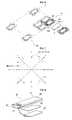
- FIGS. 2 and 3are perspective views showing a primary core unit disposed in the non-contact charging system according to the present invention
- FIGS. 4 , 5 and 6are perspective views showing the use of the primary core unit disposed in the non-contact charging system according to the present invention.
- FIG. 7is a view showing a direction of rotation of a magnetic field depending on each mode of operation in a series resonance type converter provided in the non-contact charging system according to the present invention.
- FIG. 8is a perspective view showing the construction of a battery pack provided in the non-contact charging system according to the present invention.
- FIG. 9is a diagram illustrating an algorithm that executes when a battery pack, in which a secondary core unit is contained, is placed on the non-contact charging system according to the present invention.
- FIG. 10is a diagram illustrating an algorithm that execute when a foreign object made of metal is placed on the non-contact charging system according to the present invention.
- FIG. 11is a diagram illustrating the algorithm and state of the non-contact charging system according to the present invention.
- FIG. 1is a block diagram showing the construction of a non-contact charging system according to the present invention.
- the non-contact charging systemincludes a battery pack B charged by an induced electromotive force that is generated in a non-contact charger A supplied with power.
- the non-contact charger Ablocks electromagnetic waves caused by Alternating Current (AC) power (110/220 V) input using an electromagnetic wave filter 100 that is connected to the power input terminal of a wireless charging pad, and a primary rectification circuit 110 rectifies the AC power, the electromagnetic waves of which are blocked, to create DC power.
- a flyback converter 110 ′contains a transistor, stores power transferred from the primary rectification circuit 110 while the contained transistor is turned on. In contrast, the flyback converter 110 ′ simultaneously applies an input voltage to a gate driver 160 , a central processing unit 180 and an ion generation unit 182 and a driving voltage to a series resonance type converter 120 when the contained transistor is turned off.
- a current detection unit 170is interposed between the flyback converter 110 ′ and the series resonance type converter 120 , detects variation in current resulting from the approach of the battery pack B, and outputs a comparison current depending on variation in the current.
- the current detection unit 170is connected to both ends of a resistor connected to the output terminal of the flyback converter 110 ′ and the input terminal of the series resonance type converter 120 , has a differential amplifier 171 , to which signals output from both ends of the resistor are input, and a comparator/low-frequency filter 172 , coupled to the output terminal of the differential amplifier 171 .
- the current detection unit 170detects variation in current by comparing the output voltage of the differential amplifier 171 with a predetermined reference voltage, filters out a comparison current depending on the amount of variation in current, and outputs the result.
- the central processing unit 180detects the approach of the battery pack B using the comparison current input from the current detection unit 170 , controls the gate drive 160 depending not only on whether a battery pack B approaches but also on the current of a temperature protection circuit unit 183 for stopping the switching of the gate drive 160 when abnormal operation occurs or the temperature of a foreign object placed on the non-contact charging pad exceeds a predetermined temperature. Furthermore, the central processing unit 180 performs the determination of information fed back from a dust and odor sensor 181 and switches the operation mode of the ion generation unit 182 .
- the gate driver 160outputs gate signals under the control of the central processing unit 180 , and the series resonance type converter 120 adjusts the waveforms of voltage and current applied to the primary core unit 130 in response to the gate signals input from the gate driver 160 .
- the gate driver 160allows two switching devices, which are provided in the series resonance type converter 120 , to be alternately turned on in response to the gate signals output by the control of the central processing unit 180 , and allows the waveforms of the input voltage and current to be adjusted by charging and discharging parallel capacitors coupled to respective switching devices.
- the series resonance type converter 120is configured to adjust the waveforms of the voltage and the current applied to the primary core unit 130 by the gate signals.
- the primary core unit 130is configured to be switched by the series resonance type converter 120 and, therefore, generate an induced electromotive force.
- FIGS. 2 and 3are perspective views showing a primary core unit disposed in the non-contact charging system according to the present invention
- FIGS. 4 , 5 and 6are perspective views showing the use of the primary core unit disposed in the non-contact charging system according to the present invention.
- the primary core unit 130is configured such that coils Pcoil 1 and Pcoil 2 are wound around a plate core member 131 in which a central opening 132 is formed, and is configured such that pieces of amorphous metal or ferrite material, such as Cobalt Co, Iron Fe, Nickel Ni, Boron B or Silicon Si, having high magnetic permeability (>80,000) and an unbroken characteristic, are attached thereto.
- amorphous metal or ferrite materialsuch as Cobalt Co, Iron Fe, Nickel Ni, Boron B or Silicon Si, having high magnetic permeability (>80,000) and an unbroken characteristic.
- the plate core member 131is formed in a polygonal shape, it may be formed in either circular or elliptical shapes in addition to the polygonal shape.
- the central opening 132is configured such that a function, which is capable both of reducing the amount of material used and of maximizing the area for radiating heat, is provided.
- the coils Pcoil 1 and Pcoil 2are configured to be wound around the plate core member 131 in series or in parallel, and it is preferable to use a single wire, a paired wire, a Litz wire or a copper foil.
- the start points of the coils Pcoil 1 and Pcoil 2are formed by winding the coils in the same directions, and the ends of the coils Pcoil 1 and Pcoil 2 are configured to be matched with Lr and Lr′, respectively, and to be switched using two series resonance type converters.
- driven switchingadjusts the phase of a signal Q 1 and the phase of a signal Q 2 , thus inducing LC resonance, so that energy is stored in a secondary coil.
- the switching patterns of the coils Pcoil 1 and Pcoil 2are alternately generated, so that a magnetic field shown in FIG. 7 rotates 360°, and induced energy can be stored regardless of the location of the secondary coil wound in a single direction.
- primary core units 130 and 130 ′can be placed on one side of the circuit 134 in series or parallel.
- Power rectified by the secondary rectification circuit 200is supplied to a foreign object detection unit 220 , and the supplied power is applied to a charging adjustment circuit 230 a in response to the output of the foreign object detection unit 220 .
- the foreign object detection unit 220detects power at the moment at which the battery pack B that contains the secondary core unit 210 , that is, a secondary module, is placed on the non-contact charger A, and is maintained in a no load state (the current of the current detection unit is smaller than a no load reference value) by maintaining a switch Q 3 in an OFF state for a predetermined time (several tens of ms).
- the foreign object detection unit 220When a predetermined period of time has lapsed after the no load state, the foreign object detection unit 220 is switched into a load state (the current of the current detection unit is larger than the no load reference value) by maintaining the switch Q 3 in an ON state, and informs the primary coil through load modulation that the battery pack B containing the secondary core unit 210 has been placed on the non-contact charger A and, at the same time, applies power to a charging control unit 230 .
- the current of the current detection unit 170becomes smaller than the reference value of the no load state when the charging is completed and, at the same time, the secondary core unit 210 enters the no load state again, so that a fully-charging state is indicated by a Light Emitting Diode (LED) or a Liquid Crystal Display (LCD).
- LEDLight Emitting Diode
- LCDLiquid Crystal Display
- the charging control unit 230includes the charging adjustment circuit 230 a and a fuel gauge 230 b , and performs both charging adjustment and fuel gauge functions.
- the charging adjustment circuit 230 asupplies the fuel gauge 230 b with power rectified by the secondary rectification circuit 200 , and applies voltage to a RFID control unit (not shown) in response to the output of the secondary rectification circuit 200 .
- the fuel gauge 230 bsupplies a battery BAT through a protection circuit 240 with power supplied from the charging adjustment circuit 230 a , generates charging state information and periodically records the information in the RFID control unit (not shown) while monitoring the charging state of the battery BAT.
- the protection unitis coupled between the charging control unit 230 and the battery BAT, and adjusts the charging and discharging of the battery BAT depending on whether the battery BAT is to be charged or discharged.
- the RFID control unit(not shown), the RFID information of the battery BAT is stored and, at the same time, the charging state information is periodically recorded.
- the RFID control unitWhen receiving an RF carrier, the RFID control unit generates RFID data, including the stored RFID and charging state information of the battery BAT, in response to the received RF carrier, modulates the RFID data, and wirelessly transmits the modulated RFID data through a tag antenna.
- the battery BATis charged depending on the adjustment of the protection circuit unit 240 .
- the charging control unit 230is formed by integrating circuits optimized to perform both the charging control function of controlling the charging and discharging of the battery BAT using the power rectified by the secondary rectification circuit 200 , and the fuel gauge function of generating the charge state information and periodically recording the generated information while monitoring the charging state of the battery B.
- FIG. 8is a perspective view showing the construction of the battery pack provided in the non-contact charging system according to the present invention.
- the battery pack Bis configured such that a shield plate 260 having a film shape is interposed between the secondary core unit 210 and a battery case 250 , thus preventing the temperature of the battery BAT from increasing due to an induced electromotive force generated by the induction of an electromagnetic field and, therefore, enhancing the stability of the battery pack B, and is also configured such that sufficient electromotive force is generated by reducing the interference of the electromagnetic field caused by the induced electromotive force, thus enhancing the charging rate.
- the shield member 241is formed in a box form so as to surround the protection circuit unit 240 . It is preferred that the entire protection circuit unit 240 is formed by molding.
- FIG. 9is a diagram illustrating an algorithm that executes when a battery pack, in which a secondary core unit is contained, is placed in the non-contact charging system according to the present invention.
- FIG. 10is a diagram illustrating an algorithm that executes when a foreign object, which is made of metal, is placed on the non-contact charging system according to the present invention.
- FIG. 11is a diagram illustrating the algorithm and states of the non-contact charging system according to the present invention.
- the foreign detection unit 220detects instantaneous power at the same time that a battery pack B is placed on the wireless charging pad, and allows a no load state to be maintained by maintaining the switch Q 3 in an OFF state for a certain period of time.
- the foreign detection unit 220maintains the state at which the current of the current detection unit 170 becomes smaller than the no load reference value for the period of time, and then allows the no load state to be switched into a load state by maintaining the switch Q 3 in an ON state. At this time, the current of the current detection unit 170 becomes larger than the no load reference value, so that the foreign object detection unit 220 informs the primary coil through load modulation that a battery pack B containing a secondary core unit 210 has been placed on the non-contact charger A and, at the same time, applies power to the charging control unit 230 .
- the current of the current detection unit 170becomes smaller than the reference value of the no load state when the charging is completed and, at the same time, the secondary core unit 210 enters the no load state, so that a fully-charging state is indicated by a LED or a LCD.
- the poweris applied to the charging control unit 230 , and the operation mode of the ion generation unit 182 is switched by allowing the central processing unit 180 to determine information fed back from the odor sensor 181 , so that a plurality of ions generated by the ion generation unit 182 , are spread to the area around the wireless charging pad. Accordingly, the bacteria on the battery pack can be destroyed and, at the same time, the ambient air near the wireless charging pad can be purified.
- the switch Q 3is maintained in an OFF state for a certain period of time and the no load state is maintained by detecting instantaneous power at the same time that a batter pack B is placed on the wireless charging pad, and a current below the reference value is supplied and is then blocked by the central processing unit 180 to which the currents of the current detection unit 170 and the temperature protection circuit unit 183 are applied, so that damage caused by overheating is prevented.
Landscapes
- Engineering & Computer Science (AREA)
- Power Engineering (AREA)
- Computer Networks & Wireless Communication (AREA)
- Health & Medical Sciences (AREA)
- Public Health (AREA)
- Animal Behavior & Ethology (AREA)
- Life Sciences & Earth Sciences (AREA)
- General Health & Medical Sciences (AREA)
- Epidemiology (AREA)
- Veterinary Medicine (AREA)
- Signal Processing (AREA)
- Charge And Discharge Circuits For Batteries Or The Like (AREA)
- Secondary Cells (AREA)
Abstract
Description
Claims (9)
Priority Applications (3)
| Application Number | Priority Date | Filing Date | Title |
|---|---|---|---|
| US12/914,303USRE44038E1 (en) | 2005-03-21 | 2005-04-11 | No point of contact charging system |
| US13/750,494USRE48193E1 (en) | 2005-03-21 | 2005-04-11 | No point of contact charging system |
| US13/750,494US20130154559A1 (en) | 2005-03-21 | 2013-01-25 | No point of contact charging system |
Applications Claiming Priority (3)
| Application Number | Priority Date | Filing Date | Title |
|---|---|---|---|
| KR1020050023184AKR100554889B1 (en) | 2005-03-21 | 2005-03-21 | Contactless charging system |
| KR1020050023184 | 2005-03-21 | ||
| PCT/KR2005/001037WO2006101285A1 (en) | 2005-03-21 | 2005-04-11 | No point of contact charging system |
Related Parent Applications (1)
| Application Number | Title | Priority Date | Filing Date |
|---|---|---|---|
| US91430310AContinuation | 2005-03-21 | 2010-10-28 |
Related Child Applications (2)
| Application Number | Title | Priority Date | Filing Date |
|---|---|---|---|
| US91430310AReissue | 2005-03-21 | 2010-10-28 | |
| US13/750,494ReissueUS20130154559A1 (en) | 2005-03-21 | 2013-01-25 | No point of contact charging system |
Publications (2)
| Publication Number | Publication Date |
|---|---|
| US20080094027A1 US20080094027A1 (en) | 2008-04-24 |
| US7443135B2true US7443135B2 (en) | 2008-10-28 |
Family
ID=37023921
Family Applications (4)
| Application Number | Title | Priority Date | Filing Date |
|---|---|---|---|
| US13/750,494Active2026-05-11USRE48193E1 (en) | 2005-03-21 | 2005-04-11 | No point of contact charging system |
| US12/914,303CeasedUSRE44038E1 (en) | 2005-03-21 | 2005-04-11 | No point of contact charging system |
| US10/570,041CeasedUS7443135B2 (en) | 2005-03-21 | 2005-04-11 | No point of contact charging system |
| US13/750,494GrantedUS20130154559A1 (en) | 2005-03-21 | 2013-01-25 | No point of contact charging system |
Family Applications Before (2)
| Application Number | Title | Priority Date | Filing Date |
|---|---|---|---|
| US13/750,494Active2026-05-11USRE48193E1 (en) | 2005-03-21 | 2005-04-11 | No point of contact charging system |
| US12/914,303CeasedUSRE44038E1 (en) | 2005-03-21 | 2005-04-11 | No point of contact charging system |
Family Applications After (1)
| Application Number | Title | Priority Date | Filing Date |
|---|---|---|---|
| US13/750,494GrantedUS20130154559A1 (en) | 2005-03-21 | 2013-01-25 | No point of contact charging system |
Country Status (6)
| Country | Link |
|---|---|
| US (4) | USRE48193E1 (en) |
| EP (3) | EP1882292A4 (en) |
| JP (1) | JP4258568B2 (en) |
| KR (1) | KR100554889B1 (en) |
| CN (1) | CN100362725C (en) |
| WO (1) | WO2006101285A1 (en) |
Cited By (119)
| Publication number | Priority date | Publication date | Assignee | Title |
|---|---|---|---|---|
| US20080143531A1 (en)* | 2006-12-18 | 2008-06-19 | Semiconductor Energy Laboratory Co., Ltd. | Semiconductor Device |
| US20090071952A1 (en)* | 2007-09-13 | 2009-03-19 | Semiconductor Energy Laboratory Co., Ltd. | Semiconductor device and heating system |
| US20090206791A1 (en)* | 2008-02-20 | 2009-08-20 | Chun-Kil Jung | Non-Contact Power Charging System and Control Method Thereof |
| US20090224723A1 (en)* | 2008-03-07 | 2009-09-10 | Canon Kabushiki Kaisha | Charging apparatus |
| US20090278494A1 (en)* | 2008-03-03 | 2009-11-12 | Mitch Randall | Universal electrical interface for providing power to mobile devices |
| USD611900S1 (en) | 2009-07-31 | 2010-03-16 | Lin Wei Yang | Induction charger |
| USD611899S1 (en) | 2009-07-31 | 2010-03-16 | Lin Wei Yang | Induction charger |
| USD611898S1 (en) | 2009-07-17 | 2010-03-16 | Lin Wei Yang | Induction charger |
| US20100066325A1 (en)* | 2008-09-17 | 2010-03-18 | Semiconductor Energy Laboratory Co., Ltd. | Semiconductor device |
| US20100109444A1 (en)* | 2008-09-18 | 2010-05-06 | Access Business Group International Llc | Electromagnetic interference suppression |
| US20100241377A1 (en)* | 2007-11-28 | 2010-09-23 | Olympus Medical Systems Corp. | Battery management system and charger |
| US20100237013A1 (en)* | 2009-02-13 | 2010-09-23 | Millipore Corporation | Autonomous filter element |
| US20110081857A1 (en)* | 2009-10-07 | 2011-04-07 | Kwang Du Lee | Wireless power transmission/reception apparatus and method having communication function |
| US20110095618A1 (en)* | 2008-09-27 | 2011-04-28 | Schatz David A | Wireless energy transfer using repeater resonators |
| US20110133691A1 (en)* | 2007-11-20 | 2011-06-09 | Nokia Corporation | Wireless Galvanic Charging Device,Method of Operation Thereof and Mobile Electric Device to be Charged |
| US20120126745A1 (en)* | 2006-06-01 | 2012-05-24 | Mojo Mobility, Inc. | Power source, charging system, and inductive receiver for mobile devices |
| US20120313579A1 (en)* | 2010-03-26 | 2012-12-13 | Takaoki Matsumoto | Contactless power supply device and contactless charging system |
| US8439270B2 (en) | 2008-09-19 | 2013-05-14 | Semiconductor Energy Laboratory Co., Ltd. | Semiconductor device and wireless tag using the same |
| US8629654B2 (en) | 2006-01-31 | 2014-01-14 | Mojo Mobility, Inc. | System and method for inductive charging of portable devices |
| US8669676B2 (en) | 2008-09-27 | 2014-03-11 | Witricity Corporation | Wireless energy transfer across variable distances using field shaping with magnetic materials to improve the coupling factor |
| US8692412B2 (en) | 2008-09-27 | 2014-04-08 | Witricity Corporation | Temperature compensation in a wireless transfer system |
| US8723366B2 (en) | 2008-09-27 | 2014-05-13 | Witricity Corporation | Wireless energy transfer resonator enclosures |
| US8760008B2 (en) | 2005-07-12 | 2014-06-24 | Massachusetts Institute Of Technology | Wireless energy transfer over variable distances between resonators of substantially similar resonant frequencies |
| US8772973B2 (en) | 2008-09-27 | 2014-07-08 | Witricity Corporation | Integrated resonator-shield structures |
| US8805530B2 (en) | 2007-06-01 | 2014-08-12 | Witricity Corporation | Power generation for implantable devices |
| US8836273B2 (en) | 2007-07-17 | 2014-09-16 | Seiko Epson Corporation | Power reception control device, power reception device, non-contact power transmission system, electronic instrument and power reception control method |
| US8836172B2 (en) | 2008-10-01 | 2014-09-16 | Massachusetts Institute Of Technology | Efficient near-field wireless energy transfer using adiabatic system variations |
| US20140266037A1 (en)* | 2011-11-30 | 2014-09-18 | Sony Corporation | Electronic unit and power feeding system |
| US8847548B2 (en) | 2008-09-27 | 2014-09-30 | Witricity Corporation | Wireless energy transfer for implantable devices |
| US8875086B2 (en) | 2011-11-04 | 2014-10-28 | Witricity Corporation | Wireless energy transfer modeling tool |
| US20140327398A1 (en)* | 2011-12-14 | 2014-11-06 | Nec Casio Mobile Communications, Ltd. | Portable terminal apparatus and method for adjusting rfid antenna resonance frequency |
| US8890470B2 (en) | 2010-06-11 | 2014-11-18 | Mojo Mobility, Inc. | System for wireless power transfer that supports interoperability, and multi-pole magnets for use therewith |
| US8901778B2 (en) | 2008-09-27 | 2014-12-02 | Witricity Corporation | Wireless energy transfer with variable size resonators for implanted medical devices |
| US8901779B2 (en) | 2008-09-27 | 2014-12-02 | Witricity Corporation | Wireless energy transfer with resonator arrays for medical applications |
| US8907531B2 (en) | 2008-09-27 | 2014-12-09 | Witricity Corporation | Wireless energy transfer with variable size resonators for medical applications |
| US8912687B2 (en) | 2008-09-27 | 2014-12-16 | Witricity Corporation | Secure wireless energy transfer for vehicle applications |
| US8922066B2 (en) | 2008-09-27 | 2014-12-30 | Witricity Corporation | Wireless energy transfer with multi resonator arrays for vehicle applications |
| US8928276B2 (en) | 2008-09-27 | 2015-01-06 | Witricity Corporation | Integrated repeaters for cell phone applications |
| US8933594B2 (en) | 2008-09-27 | 2015-01-13 | Witricity Corporation | Wireless energy transfer for vehicles |
| US8937408B2 (en) | 2008-09-27 | 2015-01-20 | Witricity Corporation | Wireless energy transfer for medical applications |
| US8946938B2 (en) | 2008-09-27 | 2015-02-03 | Witricity Corporation | Safety systems for wireless energy transfer in vehicle applications |
| US8947186B2 (en) | 2008-09-27 | 2015-02-03 | Witricity Corporation | Wireless energy transfer resonator thermal management |
| US8957549B2 (en) | 2008-09-27 | 2015-02-17 | Witricity Corporation | Tunable wireless energy transfer for in-vehicle applications |
| US8963488B2 (en) | 2008-09-27 | 2015-02-24 | Witricity Corporation | Position insensitive wireless charging |
| US9035499B2 (en) | 2008-09-27 | 2015-05-19 | Witricity Corporation | Wireless energy transfer for photovoltaic panels |
| US9065423B2 (en) | 2008-09-27 | 2015-06-23 | Witricity Corporation | Wireless energy distribution system |
| US9093853B2 (en) | 2008-09-27 | 2015-07-28 | Witricity Corporation | Flexible resonator attachment |
| US9106203B2 (en) | 2008-09-27 | 2015-08-11 | Witricity Corporation | Secure wireless energy transfer in medical applications |
| US9105959B2 (en) | 2008-09-27 | 2015-08-11 | Witricity Corporation | Resonator enclosure |
| US9106083B2 (en) | 2011-01-18 | 2015-08-11 | Mojo Mobility, Inc. | Systems and method for positioning freedom, and support of different voltages, protocols, and power levels in a wireless power system |
| US9160203B2 (en) | 2008-09-27 | 2015-10-13 | Witricity Corporation | Wireless powered television |
| US20150311741A1 (en)* | 2014-04-28 | 2015-10-29 | Apple Inc. | Connector-free magnetic charger/winder |
| US9184595B2 (en) | 2008-09-27 | 2015-11-10 | Witricity Corporation | Wireless energy transfer in lossy environments |
| US9219378B2 (en) | 2010-11-01 | 2015-12-22 | Qualcomm Incorporated | Wireless charging of devices |
| US9246336B2 (en) | 2008-09-27 | 2016-01-26 | Witricity Corporation | Resonator optimizations for wireless energy transfer |
| US9287607B2 (en) | 2012-07-31 | 2016-03-15 | Witricity Corporation | Resonator fine tuning |
| US9306635B2 (en) | 2012-01-26 | 2016-04-05 | Witricity Corporation | Wireless energy transfer with reduced fields |
| US9318922B2 (en) | 2008-09-27 | 2016-04-19 | Witricity Corporation | Mechanically removable wireless power vehicle seat assembly |
| US9318257B2 (en) | 2011-10-18 | 2016-04-19 | Witricity Corporation | Wireless energy transfer for packaging |
| US9343922B2 (en) | 2012-06-27 | 2016-05-17 | Witricity Corporation | Wireless energy transfer for rechargeable batteries |
| US9356659B2 (en) | 2011-01-18 | 2016-05-31 | Mojo Mobility, Inc. | Chargers and methods for wireless power transfer |
| US9369182B2 (en) | 2008-09-27 | 2016-06-14 | Witricity Corporation | Wireless energy transfer using variable size resonators and system monitoring |
| US9384885B2 (en) | 2011-08-04 | 2016-07-05 | Witricity Corporation | Tunable wireless power architectures |
| US9396867B2 (en) | 2008-09-27 | 2016-07-19 | Witricity Corporation | Integrated resonator-shield structures |
| US9404954B2 (en) | 2012-10-19 | 2016-08-02 | Witricity Corporation | Foreign object detection in wireless energy transfer systems |
| USRE46111E1 (en) | 2006-10-24 | 2016-08-16 | Hanrim Postech Co., Ltd. | Non-contact charger available of wireless data and power transmission, charging battery-pack and mobile device using non-contact charger |
| US9421388B2 (en) | 2007-06-01 | 2016-08-23 | Witricity Corporation | Power generation for implantable devices |
| US9444520B2 (en) | 2008-09-27 | 2016-09-13 | Witricity Corporation | Wireless energy transfer converters |
| US9442172B2 (en) | 2011-09-09 | 2016-09-13 | Witricity Corporation | Foreign object detection in wireless energy transfer systems |
| US9444265B2 (en) | 2005-07-12 | 2016-09-13 | Massachusetts Institute Of Technology | Wireless energy transfer |
| US9449757B2 (en) | 2012-11-16 | 2016-09-20 | Witricity Corporation | Systems and methods for wireless power system with improved performance and/or ease of use |
| US9496732B2 (en) | 2011-01-18 | 2016-11-15 | Mojo Mobility, Inc. | Systems and methods for wireless power transfer |
| US9515494B2 (en) | 2008-09-27 | 2016-12-06 | Witricity Corporation | Wireless power system including impedance matching network |
| US9544683B2 (en) | 2008-09-27 | 2017-01-10 | Witricity Corporation | Wirelessly powered audio devices |
| US9577440B2 (en) | 2006-01-31 | 2017-02-21 | Mojo Mobility, Inc. | Inductive power source and charging system |
| US9595378B2 (en) | 2012-09-19 | 2017-03-14 | Witricity Corporation | Resonator enclosure |
| US9601266B2 (en) | 2008-09-27 | 2017-03-21 | Witricity Corporation | Multiple connected resonators with a single electronic circuit |
| US9602168B2 (en) | 2010-08-31 | 2017-03-21 | Witricity Corporation | Communication in wireless energy transfer systems |
| US9601270B2 (en) | 2008-09-27 | 2017-03-21 | Witricity Corporation | Low AC resistance conductor designs |
| US9722447B2 (en) | 2012-03-21 | 2017-08-01 | Mojo Mobility, Inc. | System and method for charging or powering devices, such as robots, electric vehicles, or other mobile devices or equipment |
| US9744858B2 (en) | 2008-09-27 | 2017-08-29 | Witricity Corporation | System for wireless energy distribution in a vehicle |
| US9754718B2 (en) | 2008-09-27 | 2017-09-05 | Witricity Corporation | Resonator arrays for wireless energy transfer |
| US9780573B2 (en) | 2014-02-03 | 2017-10-03 | Witricity Corporation | Wirelessly charged battery system |
| US9829599B2 (en) | 2015-03-23 | 2017-11-28 | Schneider Electric USA, Inc. | Sensor and method for foreign object detection in induction electric charger |
| US9837860B2 (en) | 2014-05-05 | 2017-12-05 | Witricity Corporation | Wireless power transmission systems for elevators |
| US9837846B2 (en) | 2013-04-12 | 2017-12-05 | Mojo Mobility, Inc. | System and method for powering or charging receivers or devices having small surface areas or volumes |
| US9843217B2 (en) | 2015-01-05 | 2017-12-12 | Witricity Corporation | Wireless energy transfer for wearables |
| US9842687B2 (en) | 2014-04-17 | 2017-12-12 | Witricity Corporation | Wireless power transfer systems with shaped magnetic components |
| US9842688B2 (en) | 2014-07-08 | 2017-12-12 | Witricity Corporation | Resonator balancing in wireless power transfer systems |
| US9857821B2 (en) | 2013-08-14 | 2018-01-02 | Witricity Corporation | Wireless power transfer frequency adjustment |
| US9893557B2 (en) | 2013-07-12 | 2018-02-13 | Schneider Electric USA, Inc. | Method and device for foreign object detection in induction electric charger |
| US9892849B2 (en) | 2014-04-17 | 2018-02-13 | Witricity Corporation | Wireless power transfer systems with shield openings |
| US9929721B2 (en) | 2015-10-14 | 2018-03-27 | Witricity Corporation | Phase and amplitude detection in wireless energy transfer systems |
| US9948145B2 (en) | 2011-07-08 | 2018-04-17 | Witricity Corporation | Wireless power transfer for a seat-vest-helmet system |
| US9952266B2 (en) | 2014-02-14 | 2018-04-24 | Witricity Corporation | Object detection for wireless energy transfer systems |
| US9954375B2 (en) | 2014-06-20 | 2018-04-24 | Witricity Corporation | Wireless power transfer systems for surfaces |
| US10018744B2 (en) | 2014-05-07 | 2018-07-10 | Witricity Corporation | Foreign object detection in wireless energy transfer systems |
| US10063104B2 (en) | 2016-02-08 | 2018-08-28 | Witricity Corporation | PWM capacitor control |
| US10063110B2 (en) | 2015-10-19 | 2018-08-28 | Witricity Corporation | Foreign object detection in wireless energy transfer systems |
| US10075019B2 (en) | 2015-11-20 | 2018-09-11 | Witricity Corporation | Voltage source isolation in wireless power transfer systems |
| TWI636634B (en)* | 2010-02-08 | 2018-09-21 | 荷蘭商飛利浦智財投資公司 | Input parasitic metal detection and mathod for same |
| US10115520B2 (en) | 2011-01-18 | 2018-10-30 | Mojo Mobility, Inc. | Systems and method for wireless power transfer |
| US10141788B2 (en) | 2015-10-22 | 2018-11-27 | Witricity Corporation | Dynamic tuning in wireless energy transfer systems |
| US10218224B2 (en) | 2008-09-27 | 2019-02-26 | Witricity Corporation | Tunable wireless energy transfer systems |
| US10248899B2 (en) | 2015-10-06 | 2019-04-02 | Witricity Corporation | RFID tag and transponder detection in wireless energy transfer systems |
| US10263473B2 (en) | 2016-02-02 | 2019-04-16 | Witricity Corporation | Controlling wireless power transfer systems |
| US10312750B2 (en) | 2009-05-25 | 2019-06-04 | Koninklijke Philips N.V. | Method and device for detecting a device in a wireless power transmission system |
| US10424976B2 (en) | 2011-09-12 | 2019-09-24 | Witricity Corporation | Reconfigurable control architectures and algorithms for electric vehicle wireless energy transfer systems |
| US10574091B2 (en) | 2014-07-08 | 2020-02-25 | Witricity Corporation | Enclosures for high power wireless power transfer systems |
| USRE48193E1 (en) | 2005-03-21 | 2020-09-01 | Ge Hybrid Technologies, Llc | No point of contact charging system |
| US11031818B2 (en) | 2017-06-29 | 2021-06-08 | Witricity Corporation | Protection and control of wireless power systems |
| US11186003B2 (en) | 2012-05-25 | 2021-11-30 | Sl Ip Company Llc | Magnetic attachment for shaving cartridge |
| US11201500B2 (en) | 2006-01-31 | 2021-12-14 | Mojo Mobility, Inc. | Efficiencies and flexibilities in inductive (wireless) charging |
| US11211975B2 (en) | 2008-05-07 | 2021-12-28 | Mojo Mobility, Inc. | Contextually aware charging of mobile devices |
| US11329511B2 (en) | 2006-06-01 | 2022-05-10 | Mojo Mobility Inc. | Power source, charging system, and inductive receiver for mobile devices |
| US11398747B2 (en) | 2011-01-18 | 2022-07-26 | Mojo Mobility, Inc. | Inductive powering and/or charging with more than one power level and/or frequency |
| US11444485B2 (en) | 2019-02-05 | 2022-09-13 | Mojo Mobility, Inc. | Inductive charging system with charging electronics physically separated from charging coil |
| US11456610B2 (en)* | 2019-02-20 | 2022-09-27 | Samsung Sdi Co., Ltd. | Internal short sensing battery control apparatus and battery control method |
| US12322971B2 (en) | 2008-12-12 | 2025-06-03 | Intel Corporation | Non-contact power receiver apparatus |
Families Citing this family (89)
| Publication number | Priority date | Publication date | Assignee | Title |
|---|---|---|---|---|
| CN101038616B (en)* | 2006-03-17 | 2010-05-12 | 上海华虹集成电路有限责任公司 | Limiting amplitude protection circuit used in non-contact IC card and radio frequency identification label |
| JP4618561B2 (en) | 2006-04-28 | 2011-01-26 | 日立工機株式会社 | Battery charger |
| KR100750201B1 (en) | 2006-06-14 | 2007-08-17 | 주식회사 한림포스텍 | Contactless outlet device for contactless power transmission to home appliance with contactless charger and its method |
| US8004235B2 (en)* | 2006-09-29 | 2011-08-23 | Access Business Group International Llc | System and method for inductively charging a battery |
| EP1914669B1 (en) | 2006-10-18 | 2011-04-20 | Semiconductor Energy Laboratory Co., Ltd. | RFID tag |
| US20100328044A1 (en)* | 2006-10-26 | 2010-12-30 | Koninklijke Philips Electronics N.V. | Inductive power system and method of operation |
| EP2086085B1 (en)* | 2006-11-08 | 2015-04-15 | Panasonic Corporation | Non-contact charger and non-contact charge system |
| US20080136364A1 (en)* | 2006-12-08 | 2008-06-12 | Russell Calvarese | Battery charging using thermoelectric devices |
| KR101061646B1 (en) | 2007-02-20 | 2011-09-01 | 세이코 엡슨 가부시키가이샤 | Transmission Control Units, Transmission Units, Electronic Devices and Solid State Power Transmission Systems |
| EP1973069B1 (en) | 2007-03-22 | 2013-01-02 | Semiconductor Energy Laboratory Co., Ltd. | Semiconductor device |
| US9466419B2 (en) | 2007-05-10 | 2016-10-11 | Auckland Uniservices Limited | Apparatus and system for charging a battery |
| KR102128564B1 (en) | 2007-05-10 | 2020-07-01 | 오클랜드 유니서비시즈 리미티드 | Multi power sourced electric vehicle |
| AU2008251143B2 (en)* | 2007-05-10 | 2011-12-22 | Auckland Uniservices Limited | Multi power sourced electric vehicle |
| KR100819753B1 (en)* | 2007-07-13 | 2008-04-08 | 주식회사 한림포스텍 | Contactless charging system for battery pack solution and its control method |
| CA2701394A1 (en)* | 2007-10-17 | 2009-04-23 | Access Business Group International Llc | Laptop and portable electronic device wireless power supply systems |
| US8729734B2 (en)* | 2007-11-16 | 2014-05-20 | Qualcomm Incorporated | Wireless power bridge |
| KR100998683B1 (en)* | 2007-11-30 | 2010-12-07 | 정춘길 | Contactless power receiver capable of multi-contact power charging |
| WO2009069844A1 (en) | 2007-11-30 | 2009-06-04 | Chun-Kil Jung | Multiple non-contact charging system of wireless power transmision and control method thereof |
| KR100971734B1 (en)* | 2007-11-30 | 2010-07-21 | 정춘길 | Contactless power transmission device capable of multi-contact charging |
| KR100971748B1 (en) | 2007-11-30 | 2010-07-22 | 정춘길 | Short range wireless power transfer system |
| KR100971737B1 (en)* | 2007-11-30 | 2010-07-21 | 정춘길 | Multi contactless charging system and control method |
| JP5556002B2 (en)* | 2008-01-09 | 2014-07-23 | セイコーエプソン株式会社 | Power transmission control device, power transmission device, non-contact power transmission system, and electronic device |
| US8338990B2 (en)* | 2008-03-13 | 2012-12-25 | Access Business Group International Llc | Inductive power supply system with multiple coil primary |
| KR101094253B1 (en)* | 2008-04-28 | 2011-12-19 | 정춘길 | Non-contact power receier, non-contact power trasmitter related to the same and non-contact power transmitting and receiving system |
| JP2009273327A (en)* | 2008-05-10 | 2009-11-19 | Sanyo Electric Co Ltd | Battery built-in apparatus and charging cradle |
| US20090284369A1 (en) | 2008-05-13 | 2009-11-19 | Qualcomm Incorporated | Transmit power control for a wireless charging system |
| JP4725664B2 (en)* | 2008-06-25 | 2011-07-13 | セイコーエプソン株式会社 | Power transmission control device, power transmission device, power reception control device, power reception device, electronic device, power transmission control method, and power reception control method |
| US8248024B2 (en)* | 2008-08-15 | 2012-08-21 | Microsoft Corporation | Advanced inductive charging pad for portable devices |
| WO2010038712A1 (en) | 2008-09-30 | 2010-04-08 | Semiconductor Energy Laboratory Co., Ltd. | Semiconductor device |
| JP5319469B2 (en)* | 2008-10-03 | 2013-10-16 | 株式会社半導体エネルギー研究所 | RFID tag |
| WO2010067763A1 (en)* | 2008-12-09 | 2010-06-17 | 株式会社 豊田自動織機 | Non-contact power transmission apparatus and power transmission method using a non-contact power transmission apparatus |
| JP5285418B2 (en)* | 2008-12-24 | 2013-09-11 | 株式会社豊田自動織機 | Resonant non-contact power supply device |
| US20100201312A1 (en) | 2009-02-10 | 2010-08-12 | Qualcomm Incorporated | Wireless power transfer for portable enclosures |
| US9312924B2 (en) | 2009-02-10 | 2016-04-12 | Qualcomm Incorporated | Systems and methods relating to multi-dimensional wireless charging |
| US8452235B2 (en)* | 2009-03-28 | 2013-05-28 | Qualcomm, Incorporated | Tracking receiver devices with wireless power systems, apparatuses, and methods |
| JP5434330B2 (en)* | 2009-07-22 | 2014-03-05 | ソニー株式会社 | Power receiving device, power transmission system, charging device, and power transmission method |
| CN102474133A (en)* | 2009-07-23 | 2012-05-23 | 富士通株式会社 | Power transmission device, wireless power supply system, and wireless power supply device |
| CA2768397A1 (en) | 2009-07-24 | 2011-01-27 | Access Business Group International Llc | Power supply |
| KR100992480B1 (en) | 2009-09-10 | 2010-11-05 | 주식회사 한림포스텍 | Non-contact charging system having function for detecting foreign material using feedback signal |
| KR101760632B1 (en) | 2010-05-19 | 2017-07-21 | 퀄컴 인코포레이티드 | Adaptive wireless energy transfer system |
| EP2393181B1 (en)* | 2010-06-02 | 2019-09-04 | FRIWO Gerätebau GmbH | Circuit for a system for a contactless, inductive energy transfer |
| CN102299570A (en)* | 2010-06-24 | 2011-12-28 | 海尔集团公司 | Wireless transmission system |
| IT1400748B1 (en)* | 2010-06-30 | 2013-07-02 | St Microelectronics Srl | SYSTEM FOR WIRELESS TRANSFER OF ENERGY BETWEEN TWO DEVICES AND SIMULTANEOUS DATA TRANSFER. |
| KR101188241B1 (en) | 2010-07-15 | 2012-10-05 | 주식회사 만도 | Battery charger using common power source for electric vehicle |
| KR101110282B1 (en)* | 2010-07-16 | 2012-02-15 | 정춘길 | Contactless power transmission control method of a contactless power receiver and a contactless power transmitter |
| US9853478B2 (en)* | 2010-07-28 | 2017-12-26 | Qualcomm Incorporated | Low power detection of wireless power devices |
| JP5691337B2 (en)* | 2010-09-17 | 2015-04-01 | ソニー株式会社 | Power supply system, charge control device, and battery device |
| DE102011005682A1 (en)* | 2011-03-17 | 2012-09-20 | Robert Bosch Gmbh | Charger, battery and method for detecting a foreign object |
| US9912201B2 (en) | 2011-04-11 | 2018-03-06 | Texas Instruments Incorporated | Systems and methods of detecting a change in object presence in a magnetic field |
| JP5071574B1 (en) | 2011-07-05 | 2012-11-14 | ソニー株式会社 | Sensing device, power receiving device, non-contact power transmission system, and sensing method |
| JP5840886B2 (en)* | 2011-07-25 | 2016-01-06 | ソニー株式会社 | Detection device, power reception device, power transmission device, non-contact power transmission system, and detection method |
| KR20130024757A (en)* | 2011-08-29 | 2013-03-08 | 주식회사 케이더파워 | The wireless charging system with the different charging ways |
| US9252846B2 (en) | 2011-09-09 | 2016-02-02 | Qualcomm Incorporated | Systems and methods for detecting and identifying a wireless power device |
| EP3193456B1 (en) | 2011-12-22 | 2018-12-12 | TreeFrog Developments, Inc. | Accessories for use with housing for an electronic device |
| CN102545398B (en)* | 2012-01-20 | 2014-01-15 | 北京科技大学 | Non-contact power supply device for shaft-mounted electronic equipment on rotating body |
| JP5924964B2 (en)* | 2012-02-07 | 2016-05-25 | シャープ株式会社 | Communication terminal |
| US9558883B2 (en)* | 2012-05-02 | 2017-01-31 | Samsung Electronics Co., Ltd | Power transmitter and method for controlling power transmission |
| CA2880430A1 (en) | 2012-07-30 | 2014-02-06 | Treefrog Developments, Inc. | Weatherproof loudspeaker and speaker assembly |
| KR101441994B1 (en) | 2012-11-14 | 2014-09-18 | 파나소닉 주식회사 | Contactless power supplying device |
| EP3211748B1 (en)* | 2012-12-18 | 2019-03-06 | Nucleus Scientific, Inc. | Nonlinear system identification for optimization of wireless power transfer |
| KR20140099822A (en)* | 2013-02-04 | 2014-08-13 | 엘지전자 주식회사 | Wireless power transmitting apparatus |
| KR101949954B1 (en) | 2013-06-07 | 2019-02-19 | 삼성전자주식회사 | Wireless power transmission apparatus for high efficient energy charging |
| EP3042452B1 (en)* | 2013-08-09 | 2018-10-03 | Intel Corporation | Coil for mobile device context-driven switching and wireless charging |
| JP6499185B2 (en) | 2014-02-23 | 2019-04-10 | アップル インコーポレイテッドApple Inc. | Impedance matching of inductive power transfer systems |
| US10032557B1 (en) | 2014-05-29 | 2018-07-24 | Apple Inc. | Tuning of primary and secondary resonant frequency for improved efficiency of inductive power transfer |
| US9537353B1 (en) | 2014-06-03 | 2017-01-03 | Apple Inc. | Methods for detecting mated coils |
| US9685814B1 (en) | 2014-06-13 | 2017-06-20 | Apple Inc. | Detection of coil coupling in an inductive charging system |
| US9813041B1 (en) | 2014-07-31 | 2017-11-07 | Apple Inc. | Automatic boost control for resonant coupled coils |
| US10014733B2 (en) | 2014-08-28 | 2018-07-03 | Apple Inc. | Temperature management in a wireless energy transfer system |
| US10193372B2 (en) | 2014-09-02 | 2019-01-29 | Apple Inc. | Operating an inductive energy transfer system |
| US10003218B2 (en)* | 2014-12-20 | 2018-06-19 | Intel Corporation | Chassis design for wireless-charging coil integration for computing systems |
| JP2016127740A (en)* | 2015-01-06 | 2016-07-11 | 東芝テック株式会社 | Information processing apparatus and peripheral equipment |
| US9425644B1 (en) | 2015-06-03 | 2016-08-23 | Thor Charger Company | Method and apparatus for charging an electrically chargeable device utilizing resonating magnetic oscillations in the apparatus |
| US10148117B2 (en) | 2015-06-29 | 2018-12-04 | Wireless Advanced Vehicle Electrification, Inc. | Low inductance pad winding using a matched winding of multiple spirals |
| US10666084B2 (en) | 2015-07-10 | 2020-05-26 | Apple Inc. | Detection and notification of an unpowered releasable charging device |
| US11689856B2 (en) | 2015-11-19 | 2023-06-27 | The Lovesac Company | Electronic furniture systems with integrated induction charger |
| KR101698045B1 (en)* | 2016-09-05 | 2017-01-20 | 김재범 | Air purifier comprising wireless charging device |
| US10644531B1 (en) | 2016-09-22 | 2020-05-05 | Apple Inc. | Adaptable power rectifier for wireless charger system |
| CN110268597A (en)* | 2017-02-08 | 2019-09-20 | 三菱电机工程技术株式会社 | Transmission of electricity side apparatus |
| US10523063B2 (en) | 2017-04-07 | 2019-12-31 | Apple Inc. | Common mode noise compensation in wireless power systems |
| US10389274B2 (en) | 2017-04-07 | 2019-08-20 | Apple Inc. | Boosted output inverter for electronic devices |
| CN111742464A (en) | 2017-12-22 | 2020-10-02 | 无线先进车辆电气化有限公司 | Wireless Power Transfer Pad with Multiple Windings |
| CN108054574B (en)* | 2017-12-25 | 2025-01-10 | 卧龙电气集团辽宁荣信电气传动有限公司 | A connection structure for charging shore-based vessels |
| US11462943B2 (en) | 2018-01-30 | 2022-10-04 | Wireless Advanced Vehicle Electrification, Llc | DC link charging of capacitor in a wireless power transfer pad |
| US11437854B2 (en) | 2018-02-12 | 2022-09-06 | Wireless Advanced Vehicle Electrification, Llc | Variable wireless power transfer system |
| US11243264B2 (en)* | 2020-04-22 | 2022-02-08 | Renesas Electronics Corporation | Abnormal power supply voltage detection device and method for detecting abnormal power supply voltage |
| KR102419356B1 (en)* | 2020-06-26 | 2022-07-11 | 이종성 | Mobile phone charger having sterilization function |
| CN112288068B (en)* | 2020-10-24 | 2024-02-27 | 卓捷创芯科技(深圳)有限公司 | Positive feedback latch amplitude limiting control circuit and method for passive radio frequency identification tag |
| US11670971B2 (en)* | 2020-11-12 | 2023-06-06 | Delta Electronics (Shanghai) Co., Ltd. | Wireless power transmission device and foreign object detection method thereof |
Citations (10)
| Publication number | Priority date | Publication date | Assignee | Title |
|---|---|---|---|---|
| JPH0467732A (en) | 1990-07-06 | 1992-03-03 | Seiko Instr Inc | Wireless charging system |
| JPH09103037A (en) | 1995-10-05 | 1997-04-15 | Nippon Ido Tsushin Kk | Power supply device, power supply device and power supply system |
| US6118249A (en)* | 1998-08-19 | 2000-09-12 | Perdix Oy | Charger with inductive power transmission for batteries in a mobile electrical device |
| KR20020035242A (en) | 2000-11-06 | 2002-05-11 | 조규형 | Charger for use in a portable device |
| KR20020057469A (en) | 2001-01-05 | 2002-07-11 | 윤종용 | A coreless low-profile pcb transformer and contactless battery charger using the pcb transformer |
| JP2002209344A (en) | 2001-01-12 | 2002-07-26 | Matsushita Electric Works Ltd | Noncontact power transmission apparatus |
| JP2002272020A (en) | 2001-03-09 | 2002-09-20 | Sony Corp | Non-contact power transmission apparatus and non- contact charging apparatus |
| US6683438B2 (en)* | 2001-01-05 | 2004-01-27 | Samsung Electronics Co., Ltd. | Contactless battery charger |
| US20050189910A1 (en)* | 2002-06-10 | 2005-09-01 | Hui Shu-Yuen R. | Planar inductive battery charger |
| KR20050122669A (en) | 2004-06-25 | 2005-12-29 | 주식회사 한림포스텍 | Wireless charging pad and battery pack applied radio frequency identification technology |
Family Cites Families (20)
| Publication number | Priority date | Publication date | Assignee | Title |
|---|---|---|---|---|
| US5568036A (en) | 1994-12-02 | 1996-10-22 | Delco Electronics Corp. | Contactless battery charging system with high voltage cable |
| JPH0913037A (en) | 1995-07-03 | 1997-01-14 | Nippon Carbide Ind Co Inc | Encapsulated flame retardant composition |
| JPH1014124A (en)* | 1996-06-19 | 1998-01-16 | Tdk Corp | Non-contact power transmission equipment |
| US5963012A (en) | 1998-07-13 | 1999-10-05 | Motorola, Inc. | Wireless battery charging system having adaptive parameter sensing |
| US20030001543A1 (en)* | 2001-06-28 | 2003-01-02 | Eisenbraun Kenneth D. | Device charger |
| DE10158794B4 (en)* | 2001-11-30 | 2008-05-29 | Friwo Gerätebau Gmbh | Inductive contactless power transformer |
| US7239110B2 (en) | 2002-05-13 | 2007-07-03 | Splashpower Limited | Primary units, methods and systems for contact-less power transfer |
| GB2388716B (en) | 2002-05-13 | 2004-10-20 | Splashpower Ltd | Improvements relating to contact-less power transfer |
| GB0210886D0 (en) | 2002-05-13 | 2002-06-19 | Zap Wireless Technologies Ltd | Improvements relating to contact-less power transfer |
| US6906495B2 (en) | 2002-05-13 | 2005-06-14 | Splashpower Limited | Contact-less power transfer |
| US6844702B2 (en)* | 2002-05-16 | 2005-01-18 | Koninklijke Philips Electronics N.V. | System, method and apparatus for contact-less battery charging with dynamic control |
| US6909495B2 (en) | 2002-08-13 | 2005-06-21 | Diamond Power International, Inc. | Emissivity probe |
| KR20040048286A (en) | 2002-12-02 | 2004-06-07 | 이효상 | System for lottery ticket service providing variable probabilty of lucky number and method therefor |
| KR100488524B1 (en)* | 2003-04-09 | 2005-05-11 | 삼성전자주식회사 | Charging equipment for robot |
| EP1432097A1 (en)* | 2003-10-06 | 2004-06-23 | Siemens Aktiengesellschaft | Charging apparatus and method for contactless charging of a mobile unit |
| CN2666013Y (en)* | 2003-10-31 | 2004-12-22 | 宏碁股份有限公司 | Non-contact inductive charging device for handheld devices |
| KR100554889B1 (en) | 2005-03-21 | 2006-03-03 | 주식회사 한림포스텍 | Contactless charging system |
| KR100976161B1 (en)* | 2008-02-20 | 2010-08-16 | 정춘길 | Contactless charging system and its charging control method |
| KR200448286Y1 (en) | 2010-01-20 | 2010-03-29 | 이정미 | A folding screen - sculpture for Congratulations and Condolences |
| KR101850487B1 (en)* | 2011-06-21 | 2018-04-19 | 삼성전자주식회사 | Electric power supply control apparatus |
- 2005
- 2005-03-21KRKR1020050023184Apatent/KR100554889B1/ennot_activeExpired - Lifetime
- 2005-04-11USUS13/750,494patent/USRE48193E1/enactiveActive
- 2005-04-11USUS12/914,303patent/USRE44038E1/ennot_activeCeased
- 2005-04-11CNCNB2005800006685Apatent/CN100362725C/ennot_activeExpired - Lifetime
- 2005-04-11JPJP2007509392Apatent/JP4258568B2/ennot_activeExpired - Lifetime
- 2005-04-11EPEP05804905Apatent/EP1882292A4/ennot_activeCeased
- 2005-04-11USUS10/570,041patent/US7443135B2/ennot_activeCeased
- 2005-04-11WOPCT/KR2005/001037patent/WO2006101285A1/enactiveApplication Filing
- 2005-04-11EPEP19159706.1Apatent/EP3525315B1/ennot_activeExpired - Lifetime
- 2005-04-11EPEP11178723.0Apatent/EP2390984B1/ennot_activeExpired - Lifetime
- 2013
- 2013-01-25USUS13/750,494patent/US20130154559A1/enactiveGranted
Patent Citations (10)
| Publication number | Priority date | Publication date | Assignee | Title |
|---|---|---|---|---|
| JPH0467732A (en) | 1990-07-06 | 1992-03-03 | Seiko Instr Inc | Wireless charging system |
| JPH09103037A (en) | 1995-10-05 | 1997-04-15 | Nippon Ido Tsushin Kk | Power supply device, power supply device and power supply system |
| US6118249A (en)* | 1998-08-19 | 2000-09-12 | Perdix Oy | Charger with inductive power transmission for batteries in a mobile electrical device |
| KR20020035242A (en) | 2000-11-06 | 2002-05-11 | 조규형 | Charger for use in a portable device |
| KR20020057469A (en) | 2001-01-05 | 2002-07-11 | 윤종용 | A coreless low-profile pcb transformer and contactless battery charger using the pcb transformer |
| US6683438B2 (en)* | 2001-01-05 | 2004-01-27 | Samsung Electronics Co., Ltd. | Contactless battery charger |
| JP2002209344A (en) | 2001-01-12 | 2002-07-26 | Matsushita Electric Works Ltd | Noncontact power transmission apparatus |
| JP2002272020A (en) | 2001-03-09 | 2002-09-20 | Sony Corp | Non-contact power transmission apparatus and non- contact charging apparatus |
| US20050189910A1 (en)* | 2002-06-10 | 2005-09-01 | Hui Shu-Yuen R. | Planar inductive battery charger |
| KR20050122669A (en) | 2004-06-25 | 2005-12-29 | 주식회사 한림포스텍 | Wireless charging pad and battery pack applied radio frequency identification technology |
Cited By (258)
| Publication number | Priority date | Publication date | Assignee | Title |
|---|---|---|---|---|
| USRE48193E1 (en) | 2005-03-21 | 2020-09-01 | Ge Hybrid Technologies, Llc | No point of contact charging system |
| US8760007B2 (en) | 2005-07-12 | 2014-06-24 | Massachusetts Institute Of Technology | Wireless energy transfer with high-Q to more than one device |
| US8760008B2 (en) | 2005-07-12 | 2014-06-24 | Massachusetts Institute Of Technology | Wireless energy transfer over variable distances between resonators of substantially similar resonant frequencies |
| US9444265B2 (en) | 2005-07-12 | 2016-09-13 | Massachusetts Institute Of Technology | Wireless energy transfer |
| US9450422B2 (en) | 2005-07-12 | 2016-09-20 | Massachusetts Institute Of Technology | Wireless energy transfer |
| US9450421B2 (en) | 2005-07-12 | 2016-09-20 | Massachusetts Institute Of Technology | Wireless non-radiative energy transfer |
| US8772972B2 (en) | 2005-07-12 | 2014-07-08 | Massachusetts Institute Of Technology | Wireless energy transfer across a distance to a moving device |
| US8766485B2 (en) | 2005-07-12 | 2014-07-01 | Massachusetts Institute Of Technology | Wireless energy transfer over distances to a moving device |
| US10097044B2 (en) | 2005-07-12 | 2018-10-09 | Massachusetts Institute Of Technology | Wireless energy transfer |
| US8772971B2 (en) | 2005-07-12 | 2014-07-08 | Massachusetts Institute Of Technology | Wireless energy transfer across variable distances with high-Q capacitively-loaded conducting-wire loops |
| US11685271B2 (en) | 2005-07-12 | 2023-06-27 | Massachusetts Institute Of Technology | Wireless non-radiative energy transfer |
| US9509147B2 (en) | 2005-07-12 | 2016-11-29 | Massachusetts Institute Of Technology | Wireless energy transfer |
| US11685270B2 (en) | 2005-07-12 | 2023-06-27 | Mit | Wireless energy transfer |
| US9065286B2 (en) | 2005-07-12 | 2015-06-23 | Massachusetts Institute Of Technology | Wireless non-radiative energy transfer |
| US8791599B2 (en) | 2005-07-12 | 2014-07-29 | Massachusetts Institute Of Technology | Wireless energy transfer to a moving device between high-Q resonators |
| US10666091B2 (en) | 2005-07-12 | 2020-05-26 | Massachusetts Institute Of Technology | Wireless non-radiative energy transfer |
| US9831722B2 (en) | 2005-07-12 | 2017-11-28 | Massachusetts Institute Of Technology | Wireless non-radiative energy transfer |
| US10141790B2 (en) | 2005-07-12 | 2018-11-27 | Massachusetts Institute Of Technology | Wireless non-radiative energy transfer |
| US11404909B2 (en) | 2006-01-31 | 2022-08-02 | Mojo Mobillity Inc. | Systems for inductive charging of portable devices that include a frequency-dependent shield for reduction of electromagnetic interference and heat during inductive charging |
| US12027873B2 (en) | 2006-01-31 | 2024-07-02 | Mojo Mobility Inc. | System and method for inductive charging of portable devices |
| US11342792B2 (en) | 2006-01-31 | 2022-05-24 | Mojo Mobility, Inc. | System and method for inductive charging of portable devices |
| US8947047B2 (en) | 2006-01-31 | 2015-02-03 | Mojo Mobility, Inc. | Efficiency and flexibility in inductive charging |
| US11316371B1 (en) | 2006-01-31 | 2022-04-26 | Mojo Mobility, Inc. | System and method for inductive charging of portable devices |
| US9793721B2 (en) | 2006-01-31 | 2017-10-17 | Mojo Mobility, Inc. | Distributed charging of mobile devices |
| US11201500B2 (en) | 2006-01-31 | 2021-12-14 | Mojo Mobility, Inc. | Efficiencies and flexibilities in inductive (wireless) charging |
| US8629654B2 (en) | 2006-01-31 | 2014-01-14 | Mojo Mobility, Inc. | System and method for inductive charging of portable devices |
| US9276437B2 (en) | 2006-01-31 | 2016-03-01 | Mojo Mobility, Inc. | System and method that provides efficiency and flexiblity in inductive charging |
| US11569685B2 (en) | 2006-01-31 | 2023-01-31 | Mojo Mobility Inc. | System and method for inductive charging of portable devices |
| US11462942B2 (en) | 2006-01-31 | 2022-10-04 | Mojo Mobility, Inc. | Efficiencies and method flexibilities in inductive (wireless) charging |
| US11411433B2 (en) | 2006-01-31 | 2022-08-09 | Mojo Mobility, Inc. | Multi-coil system for inductive charging of portable devices at different power levels |
| US12040625B2 (en) | 2006-01-31 | 2024-07-16 | Mojo Mobility Inc. | System and method for inductive charging of portable devices |
| US9577440B2 (en) | 2006-01-31 | 2017-02-21 | Mojo Mobility, Inc. | Inductive power source and charging system |
| US11349315B2 (en) | 2006-01-31 | 2022-05-31 | Mojo Mobility, Inc. | System and method for inductive charging of portable devices |
| US9461501B2 (en) | 2006-06-01 | 2016-10-04 | Mojo Mobility, Inc. | Power source, charging system, and inductive receiver for mobile devices |
| US11121580B2 (en) | 2006-06-01 | 2021-09-14 | Mojo Mobility, Inc. | Power source, charging system, and inductive receiver for mobile devices |
| US11329511B2 (en) | 2006-06-01 | 2022-05-10 | Mojo Mobility Inc. | Power source, charging system, and inductive receiver for mobile devices |
| US8629652B2 (en)* | 2006-06-01 | 2014-01-14 | Mojo Mobility, Inc. | Power source, charging system, and inductive receiver for mobile devices |
| US11601017B2 (en) | 2006-06-01 | 2023-03-07 | Mojo Mobility Inc. | Power source, charging system, and inductive receiver for mobile devices |
| US20120126745A1 (en)* | 2006-06-01 | 2012-05-24 | Mojo Mobility, Inc. | Power source, charging system, and inductive receiver for mobile devices |
| USRE46111E1 (en) | 2006-10-24 | 2016-08-16 | Hanrim Postech Co., Ltd. | Non-contact charger available of wireless data and power transmission, charging battery-pack and mobile device using non-contact charger |
| US8160636B2 (en) | 2006-12-18 | 2012-04-17 | Semiconductor Energy Laboratory Co., Ltd. | Semiconductor device |
| US20080143531A1 (en)* | 2006-12-18 | 2008-06-19 | Semiconductor Energy Laboratory Co., Ltd. | Semiconductor Device |
| US8805530B2 (en) | 2007-06-01 | 2014-08-12 | Witricity Corporation | Power generation for implantable devices |
| US10420951B2 (en) | 2007-06-01 | 2019-09-24 | Witricity Corporation | Power generation for implantable devices |
| US9843230B2 (en) | 2007-06-01 | 2017-12-12 | Witricity Corporation | Wireless power harvesting and transmission with heterogeneous signals |
| US9943697B2 (en) | 2007-06-01 | 2018-04-17 | Witricity Corporation | Power generation for implantable devices |
| US9318898B2 (en) | 2007-06-01 | 2016-04-19 | Witricity Corporation | Wireless power harvesting and transmission with heterogeneous signals |
| US9421388B2 (en) | 2007-06-01 | 2016-08-23 | Witricity Corporation | Power generation for implantable devices |
| US10348136B2 (en) | 2007-06-01 | 2019-07-09 | Witricity Corporation | Wireless power harvesting and transmission with heterogeneous signals |
| US9101777B2 (en) | 2007-06-01 | 2015-08-11 | Witricity Corporation | Wireless power harvesting and transmission with heterogeneous signals |
| US9095729B2 (en) | 2007-06-01 | 2015-08-04 | Witricity Corporation | Wireless power harvesting and transmission with heterogeneous signals |
| US10516299B2 (en) | 2007-07-17 | 2019-12-24 | Seiko Epson Corporation | Power reception device and power reception method for non-contact power transmission |
| US8836273B2 (en) | 2007-07-17 | 2014-09-16 | Seiko Epson Corporation | Power reception control device, power reception device, non-contact power transmission system, electronic instrument and power reception control method |
| US10903695B2 (en) | 2007-07-17 | 2021-01-26 | Seiko Epson Corporation | Power reception device and power reception method for non-contact power transmission |
| US9673636B2 (en) | 2007-07-17 | 2017-06-06 | Seiko Epson Corporation | Power reception control device and power reception control method for non-contact power transmission |
| US9209636B2 (en) | 2007-07-17 | 2015-12-08 | Seiko Epson Corporation | Power reception control device and power reception control method for non-contact power transmission |
| US10257884B2 (en)* | 2007-09-13 | 2019-04-09 | Semiconductor Energy Laboratory Co., Ltd. | Semiconductor device and heating system |
| US20090071952A1 (en)* | 2007-09-13 | 2009-03-19 | Semiconductor Energy Laboratory Co., Ltd. | Semiconductor device and heating system |
| US20110133691A1 (en)* | 2007-11-20 | 2011-06-09 | Nokia Corporation | Wireless Galvanic Charging Device,Method of Operation Thereof and Mobile Electric Device to be Charged |
| US20100241377A1 (en)* | 2007-11-28 | 2010-09-23 | Olympus Medical Systems Corp. | Battery management system and charger |
| US8131488B2 (en)* | 2007-11-28 | 2012-03-06 | Olympus Medical Systems Corp. | Battery management system and charger |
| US8030887B2 (en)* | 2008-02-20 | 2011-10-04 | Chun-Kil Jung | Non-contact power charging system and control method thereof |
| US11387677B2 (en) | 2008-02-20 | 2022-07-12 | Intel Corporation | Non-contact power charging system and control method thereof based on foreign substance detection |
| USRE46046E1 (en)* | 2008-02-20 | 2016-06-28 | Intel Corporation | Non-contact power charging system and control method thereof |
| US20090206791A1 (en)* | 2008-02-20 | 2009-08-20 | Chun-Kil Jung | Non-Contact Power Charging System and Control Method Thereof |
| US9142995B2 (en)* | 2008-02-20 | 2015-09-22 | Hanrim Postech Co., Ltd. | Apparatus and method for controlling power transmission in non-contact power charging system based on charge information received from the receiving apparatus |
| US20110316477A1 (en)* | 2008-02-20 | 2011-12-29 | Chun-Kil Jung | Non-contact power charging system and control method thereof |
| US12348056B2 (en) | 2008-02-20 | 2025-07-01 | Intel Corporation | Apparatus of non-contact power receiver utilizing transmission of a power adjustment request to a non-contact power transmitter |
| US20090278494A1 (en)* | 2008-03-03 | 2009-11-12 | Mitch Randall | Universal electrical interface for providing power to mobile devices |
| US8183828B2 (en)* | 2008-03-07 | 2012-05-22 | Canon Kabushiki Kaisha | Charging apparatus |
| US8614561B2 (en) | 2008-03-07 | 2013-12-24 | Canon Kabushiki Kaisha | Charging apparatus |
| US20090224723A1 (en)* | 2008-03-07 | 2009-09-10 | Canon Kabushiki Kaisha | Charging apparatus |
| US11606119B2 (en) | 2008-05-07 | 2023-03-14 | Mojo Mobility Inc. | Metal layer for inductive power transfer |
| US11211975B2 (en) | 2008-05-07 | 2021-12-28 | Mojo Mobility, Inc. | Contextually aware charging of mobile devices |
| US20100066325A1 (en)* | 2008-09-17 | 2010-03-18 | Semiconductor Energy Laboratory Co., Ltd. | Semiconductor device |
| US8284579B2 (en) | 2008-09-17 | 2012-10-09 | Semiconductor Energy Laboratory Co., Ltd. | Semiconductor device |
| US20100109444A1 (en)* | 2008-09-18 | 2010-05-06 | Access Business Group International Llc | Electromagnetic interference suppression |
| US9225312B2 (en) | 2008-09-18 | 2015-12-29 | Access Business Group International Llc | Electromagnetic interference suppression |
| US8878392B2 (en) | 2008-09-18 | 2014-11-04 | Access Business Group International Llc | Electromagnetic interference suppression |
| US8439270B2 (en) | 2008-09-19 | 2013-05-14 | Semiconductor Energy Laboratory Co., Ltd. | Semiconductor device and wireless tag using the same |
| US9607975B2 (en) | 2008-09-19 | 2017-03-28 | Semiconductor Energy Laboratory Co., Ltd. | Semiconductor device and wireless tag using the same |
| US9711991B2 (en) | 2008-09-27 | 2017-07-18 | Witricity Corporation | Wireless energy transfer converters |
| US11114897B2 (en) | 2008-09-27 | 2021-09-07 | Witricity Corporation | Wireless power transmission system enabling bidirectional energy flow |
| US9246336B2 (en) | 2008-09-27 | 2016-01-26 | Witricity Corporation | Resonator optimizations for wireless energy transfer |
| US9184595B2 (en) | 2008-09-27 | 2015-11-10 | Witricity Corporation | Wireless energy transfer in lossy environments |
| US12263743B2 (en) | 2008-09-27 | 2025-04-01 | Witricity Corporation | Wireless power system modules |
| US11958370B2 (en) | 2008-09-27 | 2024-04-16 | Witricity Corporation | Wireless power system modules |
| US9318922B2 (en) | 2008-09-27 | 2016-04-19 | Witricity Corporation | Mechanically removable wireless power vehicle seat assembly |
| US20110095618A1 (en)* | 2008-09-27 | 2011-04-28 | Schatz David A | Wireless energy transfer using repeater resonators |
| US8669676B2 (en) | 2008-09-27 | 2014-03-11 | Witricity Corporation | Wireless energy transfer across variable distances using field shaping with magnetic materials to improve the coupling factor |
| US11479132B2 (en) | 2008-09-27 | 2022-10-25 | Witricity Corporation | Wireless power transmission system enabling bidirectional energy flow |
| US8692412B2 (en) | 2008-09-27 | 2014-04-08 | Witricity Corporation | Temperature compensation in a wireless transfer system |
| US9369182B2 (en) | 2008-09-27 | 2016-06-14 | Witricity Corporation | Wireless energy transfer using variable size resonators and system monitoring |
| US8723366B2 (en) | 2008-09-27 | 2014-05-13 | Witricity Corporation | Wireless energy transfer resonator enclosures |
| US8729737B2 (en) | 2008-09-27 | 2014-05-20 | Witricity Corporation | Wireless energy transfer using repeater resonators |
| US9396867B2 (en) | 2008-09-27 | 2016-07-19 | Witricity Corporation | Integrated resonator-shield structures |
| US8772973B2 (en) | 2008-09-27 | 2014-07-08 | Witricity Corporation | Integrated resonator-shield structures |
| US9160203B2 (en) | 2008-09-27 | 2015-10-13 | Witricity Corporation | Wireless powered television |
| US8847548B2 (en) | 2008-09-27 | 2014-09-30 | Witricity Corporation | Wireless energy transfer for implantable devices |
| US9444520B2 (en) | 2008-09-27 | 2016-09-13 | Witricity Corporation | Wireless energy transfer converters |
| US11114896B2 (en) | 2008-09-27 | 2021-09-07 | Witricity Corporation | Wireless power system modules |
| US10673282B2 (en) | 2008-09-27 | 2020-06-02 | Witricity Corporation | Tunable wireless energy transfer systems |
| US8901778B2 (en) | 2008-09-27 | 2014-12-02 | Witricity Corporation | Wireless energy transfer with variable size resonators for implanted medical devices |
| US10559980B2 (en) | 2008-09-27 | 2020-02-11 | Witricity Corporation | Signaling in wireless power systems |
| US10536034B2 (en) | 2008-09-27 | 2020-01-14 | Witricity Corporation | Wireless energy transfer resonator thermal management |
| US8901779B2 (en) | 2008-09-27 | 2014-12-02 | Witricity Corporation | Wireless energy transfer with resonator arrays for medical applications |
| US10446317B2 (en) | 2008-09-27 | 2019-10-15 | Witricity Corporation | Object and motion detection in wireless power transfer systems |
| US9105959B2 (en) | 2008-09-27 | 2015-08-11 | Witricity Corporation | Resonator enclosure |
| US8907531B2 (en) | 2008-09-27 | 2014-12-09 | Witricity Corporation | Wireless energy transfer with variable size resonators for medical applications |
| US9496719B2 (en) | 2008-09-27 | 2016-11-15 | Witricity Corporation | Wireless energy transfer for implantable devices |
| US10410789B2 (en) | 2008-09-27 | 2019-09-10 | Witricity Corporation | Integrated resonator-shield structures |
| US9106203B2 (en) | 2008-09-27 | 2015-08-11 | Witricity Corporation | Secure wireless energy transfer in medical applications |
| US9515495B2 (en) | 2008-09-27 | 2016-12-06 | Witricity Corporation | Wireless energy transfer in lossy environments |
| US9515494B2 (en) | 2008-09-27 | 2016-12-06 | Witricity Corporation | Wireless power system including impedance matching network |
| US9544683B2 (en) | 2008-09-27 | 2017-01-10 | Witricity Corporation | Wirelessly powered audio devices |
| US9093853B2 (en) | 2008-09-27 | 2015-07-28 | Witricity Corporation | Flexible resonator attachment |
| US9577436B2 (en) | 2008-09-27 | 2017-02-21 | Witricity Corporation | Wireless energy transfer for implantable devices |
| US9584189B2 (en) | 2008-09-27 | 2017-02-28 | Witricity Corporation | Wireless energy transfer using variable size resonators and system monitoring |
| US8912687B2 (en) | 2008-09-27 | 2014-12-16 | Witricity Corporation | Secure wireless energy transfer for vehicle applications |
| US9596005B2 (en) | 2008-09-27 | 2017-03-14 | Witricity Corporation | Wireless energy transfer using variable size resonators and systems monitoring |
| US9601266B2 (en) | 2008-09-27 | 2017-03-21 | Witricity Corporation | Multiple connected resonators with a single electronic circuit |
| US10340745B2 (en) | 2008-09-27 | 2019-07-02 | Witricity Corporation | Wireless power sources and devices |
| US9601270B2 (en) | 2008-09-27 | 2017-03-21 | Witricity Corporation | Low AC resistance conductor designs |
| US9601261B2 (en)* | 2008-09-27 | 2017-03-21 | Witricity Corporation | Wireless energy transfer using repeater resonators |
| US9065423B2 (en) | 2008-09-27 | 2015-06-23 | Witricity Corporation | Wireless energy distribution system |
| US9662161B2 (en) | 2008-09-27 | 2017-05-30 | Witricity Corporation | Wireless energy transfer for medical applications |
| US9035499B2 (en) | 2008-09-27 | 2015-05-19 | Witricity Corporation | Wireless energy transfer for photovoltaic panels |
| US9698607B2 (en) | 2008-09-27 | 2017-07-04 | Witricity Corporation | Secure wireless energy transfer |
| US8963488B2 (en) | 2008-09-27 | 2015-02-24 | Witricity Corporation | Position insensitive wireless charging |
| US10300800B2 (en) | 2008-09-27 | 2019-05-28 | Witricity Corporation | Shielding in vehicle wireless power systems |
| US9742204B2 (en) | 2008-09-27 | 2017-08-22 | Witricity Corporation | Wireless energy transfer in lossy environments |
| US9744858B2 (en) | 2008-09-27 | 2017-08-29 | Witricity Corporation | System for wireless energy distribution in a vehicle |
| US9748039B2 (en) | 2008-09-27 | 2017-08-29 | Witricity Corporation | Wireless energy transfer resonator thermal management |
| US9754718B2 (en) | 2008-09-27 | 2017-09-05 | Witricity Corporation | Resonator arrays for wireless energy transfer |
| US9780605B2 (en) | 2008-09-27 | 2017-10-03 | Witricity Corporation | Wireless power system with associated impedance matching network |
| US10264352B2 (en) | 2008-09-27 | 2019-04-16 | Witricity Corporation | Wirelessly powered audio devices |
| US8922066B2 (en) | 2008-09-27 | 2014-12-30 | Witricity Corporation | Wireless energy transfer with multi resonator arrays for vehicle applications |
| US8957549B2 (en) | 2008-09-27 | 2015-02-17 | Witricity Corporation | Tunable wireless energy transfer for in-vehicle applications |
| US9806541B2 (en) | 2008-09-27 | 2017-10-31 | Witricity Corporation | Flexible resonator attachment |
| US10230243B2 (en) | 2008-09-27 | 2019-03-12 | Witricity Corporation | Flexible resonator attachment |
| US10218224B2 (en) | 2008-09-27 | 2019-02-26 | Witricity Corporation | Tunable wireless energy transfer systems |
| US8947186B2 (en) | 2008-09-27 | 2015-02-03 | Witricity Corporation | Wireless energy transfer resonator thermal management |
| US8928276B2 (en) | 2008-09-27 | 2015-01-06 | Witricity Corporation | Integrated repeaters for cell phone applications |
| US10097011B2 (en) | 2008-09-27 | 2018-10-09 | Witricity Corporation | Wireless energy transfer for photovoltaic panels |
| US8933594B2 (en) | 2008-09-27 | 2015-01-13 | Witricity Corporation | Wireless energy transfer for vehicles |
| US9843228B2 (en) | 2008-09-27 | 2017-12-12 | Witricity Corporation | Impedance matching in wireless power systems |
| US10084348B2 (en) | 2008-09-27 | 2018-09-25 | Witricity Corporation | Wireless energy transfer for implantable devices |
| US8937408B2 (en) | 2008-09-27 | 2015-01-20 | Witricity Corporation | Wireless energy transfer for medical applications |
| US8946938B2 (en) | 2008-09-27 | 2015-02-03 | Witricity Corporation | Safety systems for wireless energy transfer in vehicle applications |
| US9831682B2 (en) | 2008-10-01 | 2017-11-28 | Massachusetts Institute Of Technology | Efficient near-field wireless energy transfer using adiabatic system variations |
| US8836172B2 (en) | 2008-10-01 | 2014-09-16 | Massachusetts Institute Of Technology | Efficient near-field wireless energy transfer using adiabatic system variations |
| US12322971B2 (en) | 2008-12-12 | 2025-06-03 | Intel Corporation | Non-contact power receiver apparatus |
| US20100237013A1 (en)* | 2009-02-13 | 2010-09-23 | Millipore Corporation | Autonomous filter element |
| US10312750B2 (en) | 2009-05-25 | 2019-06-04 | Koninklijke Philips N.V. | Method and device for detecting a device in a wireless power transmission system |
| US11050304B2 (en) | 2009-05-25 | 2021-06-29 | Koninklijke Philips N.V. | Method and device for detecting a device in a wireless power transmission system |
| USD611898S1 (en) | 2009-07-17 | 2010-03-16 | Lin Wei Yang | Induction charger |
| USD611900S1 (en) | 2009-07-31 | 2010-03-16 | Lin Wei Yang | Induction charger |
| USD611899S1 (en) | 2009-07-31 | 2010-03-16 | Lin Wei Yang | Induction charger |
| US8760006B2 (en)* | 2009-10-07 | 2014-06-24 | Samsung Electro-Mechanics Co., Ltd. | Wireless power transmission/reception apparatus and method having communication function |
| US20110081857A1 (en)* | 2009-10-07 | 2011-04-07 | Kwang Du Lee | Wireless power transmission/reception apparatus and method having communication function |
| TWI636634B (en)* | 2010-02-08 | 2018-09-21 | 荷蘭商飛利浦智財投資公司 | Input parasitic metal detection and mathod for same |
| US20120313579A1 (en)* | 2010-03-26 | 2012-12-13 | Takaoki Matsumoto | Contactless power supply device and contactless charging system |
| US11283306B2 (en) | 2010-06-11 | 2022-03-22 | Mojo Mobility, Inc. | Magnet with multiple opposing poles on a surface for use with magnetically sensitive components |
| US12278045B2 (en) | 2010-06-11 | 2025-04-15 | Mojo Mobility Inc. | Magnet with multiple opposing poles on a surface for use with magnetically sensitive components |
| US10714986B2 (en) | 2010-06-11 | 2020-07-14 | Mojo Mobility, Inc. | Intelligent initiation of inductive charging process |
| US12293872B2 (en) | 2010-06-11 | 2025-05-06 | Mojo Mobility Inc. | Magnetic structure with multiple opposing poles on a surface for use with magnetically sensitive components |
| US8901881B2 (en) | 2010-06-11 | 2014-12-02 | Mojo Mobility, Inc. | Intelligent initiation of inductive charging process |
| US8896264B2 (en) | 2010-06-11 | 2014-11-25 | Mojo Mobility, Inc. | Inductive charging with support for multiple charging protocols |
| US8890470B2 (en) | 2010-06-11 | 2014-11-18 | Mojo Mobility, Inc. | System for wireless power transfer that supports interoperability, and multi-pole magnets for use therewith |
| US12400779B1 (en) | 2010-06-11 | 2025-08-26 | Mojo Mobility Inc. | Magnetic structure for inductive charging |
| US9602168B2 (en) | 2010-08-31 | 2017-03-21 | Witricity Corporation | Communication in wireless energy transfer systems |
| US9219378B2 (en) | 2010-11-01 | 2015-12-22 | Qualcomm Incorporated | Wireless charging of devices |
| US11398747B2 (en) | 2011-01-18 | 2022-07-26 | Mojo Mobility, Inc. | Inductive powering and/or charging with more than one power level and/or frequency |
| US9112363B2 (en) | 2011-01-18 | 2015-08-18 | Mojo Mobility, Inc. | Intelligent charging of multiple electric or electronic devices with a multi-dimensional inductive charger |
| US9112362B2 (en) | 2011-01-18 | 2015-08-18 | Mojo Mobility, Inc. | Methods for improved transfer efficiency in a multi-dimensional inductive charger |
| US12046414B2 (en) | 2011-01-18 | 2024-07-23 | Mojo Mobility Inc. | Powering and/or charging with more than one protocol |
| US9356659B2 (en) | 2011-01-18 | 2016-05-31 | Mojo Mobility, Inc. | Chargers and methods for wireless power transfer |
| US9106083B2 (en) | 2011-01-18 | 2015-08-11 | Mojo Mobility, Inc. | Systems and method for positioning freedom, and support of different voltages, protocols, and power levels in a wireless power system |
| US9178369B2 (en) | 2011-01-18 | 2015-11-03 | Mojo Mobility, Inc. | Systems and methods for providing positioning freedom, and support of different voltages, protocols, and power levels in a wireless power system |
| US9496732B2 (en) | 2011-01-18 | 2016-11-15 | Mojo Mobility, Inc. | Systems and methods for wireless power transfer |
| US10115520B2 (en) | 2011-01-18 | 2018-10-30 | Mojo Mobility, Inc. | Systems and method for wireless power transfer |
| US9112364B2 (en) | 2011-01-18 | 2015-08-18 | Mojo Mobility, Inc. | Multi-dimensional inductive charger and applications thereof |
| US9948145B2 (en) | 2011-07-08 | 2018-04-17 | Witricity Corporation | Wireless power transfer for a seat-vest-helmet system |
| US9384885B2 (en) | 2011-08-04 | 2016-07-05 | Witricity Corporation | Tunable wireless power architectures |
| US11621585B2 (en) | 2011-08-04 | 2023-04-04 | Witricity Corporation | Tunable wireless power architectures |
| US9787141B2 (en) | 2011-08-04 | 2017-10-10 | Witricity Corporation | Tunable wireless power architectures |
| US10734842B2 (en) | 2011-08-04 | 2020-08-04 | Witricity Corporation | Tunable wireless power architectures |
| US9442172B2 (en) | 2011-09-09 | 2016-09-13 | Witricity Corporation | Foreign object detection in wireless energy transfer systems |
| US10778047B2 (en) | 2011-09-09 | 2020-09-15 | Witricity Corporation | Foreign object detection in wireless energy transfer systems |
| US10027184B2 (en) | 2011-09-09 | 2018-07-17 | Witricity Corporation | Foreign object detection in wireless energy transfer systems |
| US11097618B2 (en) | 2011-09-12 | 2021-08-24 | Witricity Corporation | Reconfigurable control architectures and algorithms for electric vehicle wireless energy transfer systems |
| US10424976B2 (en) | 2011-09-12 | 2019-09-24 | Witricity Corporation | Reconfigurable control architectures and algorithms for electric vehicle wireless energy transfer systems |
| US9318257B2 (en) | 2011-10-18 | 2016-04-19 | Witricity Corporation | Wireless energy transfer for packaging |
| US8875086B2 (en) | 2011-11-04 | 2014-10-28 | Witricity Corporation | Wireless energy transfer modeling tool |
| US10224755B2 (en) | 2011-11-30 | 2019-03-05 | Sony Corporation | Electronic unit for notifying user of charging state in non-contact power feeding system |
| US9450447B2 (en)* | 2011-11-30 | 2016-09-20 | Sony Corporation | Electronic system for notifying user of battery charging state |
| US20140266037A1 (en)* | 2011-11-30 | 2014-09-18 | Sony Corporation | Electronic unit and power feeding system |
| US10541569B2 (en) | 2011-11-30 | 2020-01-21 | Sony Corporation | Electronic unit for notifying user of charging state in non-contact power feeding system |
| US11088575B2 (en) | 2011-11-30 | 2021-08-10 | Sony Corporation | Reliably informing user of electronic device state during charging |
| US20140327398A1 (en)* | 2011-12-14 | 2014-11-06 | Nec Casio Mobile Communications, Ltd. | Portable terminal apparatus and method for adjusting rfid antenna resonance frequency |
| US9306635B2 (en) | 2012-01-26 | 2016-04-05 | Witricity Corporation | Wireless energy transfer with reduced fields |
| US9722447B2 (en) | 2012-03-21 | 2017-08-01 | Mojo Mobility, Inc. | System and method for charging or powering devices, such as robots, electric vehicles, or other mobile devices or equipment |
| US11186003B2 (en) | 2012-05-25 | 2021-11-30 | Sl Ip Company Llc | Magnetic attachment for shaving cartridge |
| US9343922B2 (en) | 2012-06-27 | 2016-05-17 | Witricity Corporation | Wireless energy transfer for rechargeable batteries |
| US10158251B2 (en) | 2012-06-27 | 2018-12-18 | Witricity Corporation | Wireless energy transfer for rechargeable batteries |
| US9287607B2 (en) | 2012-07-31 | 2016-03-15 | Witricity Corporation | Resonator fine tuning |
| US9595378B2 (en) | 2012-09-19 | 2017-03-14 | Witricity Corporation | Resonator enclosure |
| US9404954B2 (en) | 2012-10-19 | 2016-08-02 | Witricity Corporation | Foreign object detection in wireless energy transfer systems |
| US10686337B2 (en) | 2012-10-19 | 2020-06-16 | Witricity Corporation | Foreign object detection in wireless energy transfer systems |
| US10211681B2 (en) | 2012-10-19 | 2019-02-19 | Witricity Corporation | Foreign object detection in wireless energy transfer systems |
| US9465064B2 (en) | 2012-10-19 | 2016-10-11 | Witricity Corporation | Foreign object detection in wireless energy transfer systems |
| US9842684B2 (en) | 2012-11-16 | 2017-12-12 | Witricity Corporation | Systems and methods for wireless power system with improved performance and/or ease of use |
| US10186372B2 (en) | 2012-11-16 | 2019-01-22 | Witricity Corporation | Systems and methods for wireless power system with improved performance and/or ease of use |
| US9449757B2 (en) | 2012-11-16 | 2016-09-20 | Witricity Corporation | Systems and methods for wireless power system with improved performance and/or ease of use |
| US11114886B2 (en) | 2013-04-12 | 2021-09-07 | Mojo Mobility, Inc. | Powering or charging small-volume or small-surface receivers or devices |
| US11929202B2 (en) | 2013-04-12 | 2024-03-12 | Mojo Mobility Inc. | System and method for powering or charging receivers or devices having small surface areas or volumes |
| US9837846B2 (en) | 2013-04-12 | 2017-12-05 | Mojo Mobility, Inc. | System and method for powering or charging receivers or devices having small surface areas or volumes |
| US11292349B2 (en) | 2013-04-12 | 2022-04-05 | Mojo Mobility Inc. | System and method for powering or charging receivers or devices having small surface areas or volumes |
| US9893557B2 (en) | 2013-07-12 | 2018-02-13 | Schneider Electric USA, Inc. | Method and device for foreign object detection in induction electric charger |
| US11112814B2 (en) | 2013-08-14 | 2021-09-07 | Witricity Corporation | Impedance adjustment in wireless power transmission systems and methods |
| US9857821B2 (en) | 2013-08-14 | 2018-01-02 | Witricity Corporation | Wireless power transfer frequency adjustment |
| US11720133B2 (en) | 2013-08-14 | 2023-08-08 | Witricity Corporation | Impedance adjustment in wireless power transmission systems and methods |
| US9780573B2 (en) | 2014-02-03 | 2017-10-03 | Witricity Corporation | Wirelessly charged battery system |
| US9952266B2 (en) | 2014-02-14 | 2018-04-24 | Witricity Corporation | Object detection for wireless energy transfer systems |
| US10186373B2 (en) | 2014-04-17 | 2019-01-22 | Witricity Corporation | Wireless power transfer systems with shield openings |
| US9892849B2 (en) | 2014-04-17 | 2018-02-13 | Witricity Corporation | Wireless power transfer systems with shield openings |
| US9842687B2 (en) | 2014-04-17 | 2017-12-12 | Witricity Corporation | Wireless power transfer systems with shaped magnetic components |
| US20150311741A1 (en)* | 2014-04-28 | 2015-10-29 | Apple Inc. | Connector-free magnetic charger/winder |
| US9450446B2 (en)* | 2014-04-28 | 2016-09-20 | Apple Inc. | Connector-free magnetic charger/winder |
| US9837860B2 (en) | 2014-05-05 | 2017-12-05 | Witricity Corporation | Wireless power transmission systems for elevators |
| US10018744B2 (en) | 2014-05-07 | 2018-07-10 | Witricity Corporation | Foreign object detection in wireless energy transfer systems |
| US10371848B2 (en) | 2014-05-07 | 2019-08-06 | Witricity Corporation | Foreign object detection in wireless energy transfer systems |
| US9954375B2 (en) | 2014-06-20 | 2018-04-24 | Witricity Corporation | Wireless power transfer systems for surfaces |
| US10923921B2 (en) | 2014-06-20 | 2021-02-16 | Witricity Corporation | Wireless power transfer systems for surfaces |
| US11637458B2 (en) | 2014-06-20 | 2023-04-25 | Witricity Corporation | Wireless power transfer systems for surfaces |
| US9842688B2 (en) | 2014-07-08 | 2017-12-12 | Witricity Corporation | Resonator balancing in wireless power transfer systems |
| US10574091B2 (en) | 2014-07-08 | 2020-02-25 | Witricity Corporation | Enclosures for high power wireless power transfer systems |
| US9843217B2 (en) | 2015-01-05 | 2017-12-12 | Witricity Corporation | Wireless energy transfer for wearables |
| US9829599B2 (en) | 2015-03-23 | 2017-11-28 | Schneider Electric USA, Inc. | Sensor and method for foreign object detection in induction electric charger |
| US10248899B2 (en) | 2015-10-06 | 2019-04-02 | Witricity Corporation | RFID tag and transponder detection in wireless energy transfer systems |
| US9929721B2 (en) | 2015-10-14 | 2018-03-27 | Witricity Corporation | Phase and amplitude detection in wireless energy transfer systems |
| US10063110B2 (en) | 2015-10-19 | 2018-08-28 | Witricity Corporation | Foreign object detection in wireless energy transfer systems |
| US10141788B2 (en) | 2015-10-22 | 2018-11-27 | Witricity Corporation | Dynamic tuning in wireless energy transfer systems |
| US10651689B2 (en) | 2015-10-22 | 2020-05-12 | Witricity Corporation | Dynamic tuning in wireless energy transfer systems |
| US10651688B2 (en) | 2015-10-22 | 2020-05-12 | Witricity Corporation | Dynamic tuning in wireless energy transfer systems |
| US10075019B2 (en) | 2015-11-20 | 2018-09-11 | Witricity Corporation | Voltage source isolation in wireless power transfer systems |
| US10637292B2 (en) | 2016-02-02 | 2020-04-28 | Witricity Corporation | Controlling wireless power transfer systems |
| US10263473B2 (en) | 2016-02-02 | 2019-04-16 | Witricity Corporation | Controlling wireless power transfer systems |
| US10063104B2 (en) | 2016-02-08 | 2018-08-28 | Witricity Corporation | PWM capacitor control |
| US11807115B2 (en) | 2016-02-08 | 2023-11-07 | Witricity Corporation | PWM capacitor control |
| US10913368B2 (en) | 2016-02-08 | 2021-02-09 | Witricity Corporation | PWM capacitor control |
| US11031818B2 (en) | 2017-06-29 | 2021-06-08 | Witricity Corporation | Protection and control of wireless power systems |
| US11637452B2 (en) | 2017-06-29 | 2023-04-25 | Witricity Corporation | Protection and control of wireless power systems |
| US11588351B2 (en) | 2017-06-29 | 2023-02-21 | Witricity Corporation | Protection and control of wireless power systems |
| US11043848B2 (en) | 2017-06-29 | 2021-06-22 | Witricity Corporation | Protection and control of wireless power systems |
| US11811238B2 (en) | 2019-02-05 | 2023-11-07 | Mojo Mobility Inc. | Inductive charging system with charging electronics physically separated from charging coil |
| US11444485B2 (en) | 2019-02-05 | 2022-09-13 | Mojo Mobility, Inc. | Inductive charging system with charging electronics physically separated from charging coil |
| US11456610B2 (en)* | 2019-02-20 | 2022-09-27 | Samsung Sdi Co., Ltd. | Internal short sensing battery control apparatus and battery control method |
Also Published As
| Publication number | Publication date |
|---|---|
| USRE48193E1 (en) | 2020-09-01 |
| JP2007514400A (en) | 2007-05-31 |
| EP2390984A3 (en) | 2014-05-21 |
| USRE44038E1 (en) | 2013-03-05 |
| EP3525315B1 (en) | 2025-03-05 |
| EP2390984B1 (en) | 2023-07-12 |
| KR100554889B1 (en) | 2006-03-03 |
| CN1826715A (en) | 2006-08-30 |
| WO2006101285A1 (en) | 2006-09-28 |
| US20130154559A1 (en) | 2013-06-20 |
| JP4258568B2 (en) | 2009-04-30 |
| EP1882292A4 (en) | 2010-08-11 |
| CN100362725C (en) | 2008-01-16 |
| EP2390984A2 (en) | 2011-11-30 |
| EP1882292A1 (en) | 2008-01-30 |
| US20080094027A1 (en) | 2008-04-24 |
| EP3525315A1 (en) | 2019-08-14 |
Similar Documents
| Publication | Publication Date | Title |
|---|---|---|
| US7443135B2 (en) | No point of contact charging system | |
| KR101632129B1 (en) | Systems and methods for induction charging with a closed magnetic loop | |
| KR200361755Y1 (en) | Wireless charging pad and battery pack applied radio frequency identification technology | |
| US9608480B2 (en) | Systems and methods for detecting and identifying a wireless power device | |
| US8159183B2 (en) | Contact-less power supply, contact-less charger systems and method for charging rechargeable battery cell | |
| US9153998B2 (en) | Wireless power orthogonal polarization antenna array | |
| US20140266018A1 (en) | Systems and methods for extending the power capability of a wireless charger | |
| US20080211455A1 (en) | Rechargeable Power Supply, Battery Device, Contactless Charger System And Method For Charging Rechargeable Battery Cell | |
| US20120223589A1 (en) | Waking up a wireless power transmitter from beacon mode | |
| US20130221911A1 (en) | Systems and methods for sensing reverse link signaling | |
| EP2636156A1 (en) | Wireless charging device | |
| KR100595702B1 (en) | Wireless charging pad and battery pack for two-way charging | |
| KR100564255B1 (en) | Contactless rechargeable battery pack, wireless charging method between these battery packs and system | |
| KR20060002325A (en) | Integrated circuit for processing battery information and integrated circuit for wireless charging | |
| US20240270091A1 (en) | Wireless power transfer |
Legal Events
| Date | Code | Title | Description |
|---|---|---|---|
| STCF | Information on status: patent grant | Free format text:PATENTED CASE | |
| FEPP | Fee payment procedure | Free format text:PAT HOLDER NO LONGER CLAIMS SMALL ENTITY STATUS, ENTITY STATUS SET TO UNDISCOUNTED (ORIGINAL EVENT CODE: STOL); ENTITY STATUS OF PATENT OWNER: LARGE ENTITY | |
| RF | Reissue application filed | Effective date:20101028 | |
| FPAY | Fee payment | Year of fee payment:4 | |
| AS | Assignment | Owner name:GE HYBRID TECHNOLOGIES, LLC, NEW YORK Free format text:ASSIGNMENT OF ASSIGNORS INTEREST;ASSIGNOR:HANRIM POSTECH CO., LTD;REEL/FRAME:044660/0188 Effective date:20180102 | |
| AS | Assignment | Owner name:HANRIM POSTECH CO., LTD, KOREA, REPUBLIC OF Free format text:ASSIGNMENT OF ASSIGNORS INTEREST;ASSIGNOR:CHO, KI-YOUNG;REEL/FRAME:045286/0445 Effective date:20060111 | |
| MAFP | Maintenance fee payment | Free format text:PAYMENT OF MAINTENANCE FEE, 12TH YEAR, LARGE ENTITY (ORIGINAL EVENT CODE: M1553); ENTITY STATUS OF PATENT OWNER: LARGE ENTITY Year of fee payment:12 | |
| RF | Reissue application filed | Effective date:20200602 |