US7441262B2 - Integrated VPN/firewall system - Google Patents
Integrated VPN/firewall systemDownload PDFInfo
- Publication number
- US7441262B2 US7441262B2US10/192,802US19280202AUS7441262B2US 7441262 B2US7441262 B2US 7441262B2US 19280202 AUS19280202 AUS 19280202AUS 7441262 B2US7441262 B2US 7441262B2
- Authority
- US
- United States
- Prior art keywords
- dtus
- dtu
- engine module
- flow
- incoming
- Prior art date
- Legal status (The legal status is an assumption and is not a legal conclusion. Google has not performed a legal analysis and makes no representation as to the accuracy of the status listed.)
- Expired - Fee Related, expires
Links
Images


Classifications
- H—ELECTRICITY
- H04—ELECTRIC COMMUNICATION TECHNIQUE
- H04L—TRANSMISSION OF DIGITAL INFORMATION, e.g. TELEGRAPHIC COMMUNICATION
- H04L63/00—Network architectures or network communication protocols for network security
- H04L63/02—Network architectures or network communication protocols for network security for separating internal from external traffic, e.g. firewalls
- H04L63/0227—Filtering policies
- H04L63/0254—Stateful filtering
- H—ELECTRICITY
- H04—ELECTRIC COMMUNICATION TECHNIQUE
- H04L—TRANSMISSION OF DIGITAL INFORMATION, e.g. TELEGRAPHIC COMMUNICATION
- H04L63/00—Network architectures or network communication protocols for network security
- H04L63/02—Network architectures or network communication protocols for network security for separating internal from external traffic, e.g. firewalls
- H04L63/0272—Virtual private networks
Definitions
- the present inventionrelates to the field of computer networks and is especially, but not exclusively, applicable to methods and apparatus for controlling access to a computer network by unauthorized data transmission units (DTUs)
- DTUsunauthorized data transmission units
- firewallshardware, software or a combination of both that checks any incoming traffic to determine if the traffic is legitimate or is part of a hacker's assault on the network/computer being protected.
- firewallsthere are two predominant types of firewalls in common use—application proxies and packet filters.
- Application proxiesact in place of the servers/computers to be protected when establishing/receiving connections with external computers.
- the application proxyacts as a go-between the server/computer being protected and any external traffic—any connection to the external world is established between the application proxy and the external computer and not directly between the external computer and the server/computer being protected.
- any malicious attackstheoretically occur against the application proxy and not against the critical server/computer.
- the packet filter firewall“filters” or checks all packets being received from the world external to the network being protected.
- the packet filtertypically checks the header of these packets and, if any packets have suspicious headers, the packet is dropped and the user or system administrator is notified.
- Security polices set by the user or system administratordetermine the amount of security provided by the firewall These policies are set when the firewall is configured by the administrator and can be manually adjusted as required. The user or system administrator can loosen or tighten the security provided by a firewall by controlling from which source computers traffic will be accepted.
- the firewallcan be configured to accept traffic/packets only from a select few sources/servers and any other traffic is to be discarded.
- the firewallcan be configured to accept all traffic. Typically, a happy medium between these two ends is desirable.
- firewallsWhile the above described how types of firewalls work to protect today's servers and networks, they each have their disadvantages. It is commonly accepted that while application proxies are much more secure than packet filters, they are much slower than packet filters. Conversely, packet filters, while fast, do not provide as much security.
- firewallsprovide both packet filtering functions along with application proxy functions. Such hybrid firewalls can provide either the security or the speed required by most applications. It should further be noted that the security policies enforced for a specific firewall, and hence the decisions which determine whether specific packets are to be accepted or discarded, is usually dependent on the application being shielded by the firewall. As such, e-mail applications and Internet browsers may have different applicable security policies. An e-mail application may have tighter applicable filtering security policies than an Internet browser due to the greater risk of viruses and worms being spread by way of e-mail messages.
- a TELNET applicationmay have stricter login security policies than an e-mail authentication/login application due to the greater risk of hackers trying to compromise the system by way of the TELNET application.
- One major issue with providing suitably secure connections across a firewallis the balancing act between the seemingly contrary concerns of speed and security. It has been widely accepted that the greater the security a firewall provides, the slower the connection. Conversely, the faster the connection, it is usual that the firewall security is not as strong. A solution to the firewall speed/security issue would provide as much security as required by the network while still providing acceptable transmission and reception rates.
- VPNsvirtual private networks.
- VPNsallow enterprises to have a single network spanning across multiple, geographically remote offices. In essence, a network in New York can be connected to a network in Houston with either network being able to seamlessly access files on the other network.
- These VPNsare connected across the Internet and, unfortunately, the secure nature of the VPNs require extra security processing at each end of the VPN link. Such extra processing tends to slow down those VPN links.
- DTUdata transmission unit
- DTUdata transmission unit
- such unitsmay take the form of packets, cells, frames, or any other unit as long as digital data is encapsulated within the unit.
- DTUis applicable to any and all packets, cells, frames, or any other units that implement specific protocols, standards or transmission schemes.
- digital datawill be used throughout this document to encompass all manner of voice, multimedia content, video, binary data or any other form of data or information that has been digitized and that is transmitted from one point in a network to another.
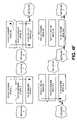
- An integrated VPN/firewall systemcomprises at least one policy engine module, a switch module, a cryptographic engine module, and at least one flow engine module.
- Each flow engine modulereceives DTUs from either side of the integrated VPN/firewall system. The DTUs are then compared to entries in a listening table and entries in a flow table. The entries in these tables consist of characteristics of DTUs expected to arrive for specific flows.
- the DTUmay be forwarded by the ingress flow engine to the egress flow engine via the switch module, and subsequently to its destination by the egress flow engine; or it may be forwarded, using the switch module, to the policy engine module for further security checking, or to the cryptographic engine module for encryption/decryption required for VPN operations.
- Entries to both listening tables and flow tablesare made by the policy engine with listening table entries generally denoting flows potentially allowed by policy to be established between computers on opposite sides of the system.
- Flow tablescorrespond to flows already allowed to be established between computers on opposite sides of the firewall system.
- the present inventionprovides a method of verifying data transmission units (DTUS) being received by a device, the method comprising the steps of:
- the present inventionprovides a system for providing firewall and virtual private networking functions to a network, the system comprising:
- the present inventionprovides a method of verifying data transmission units (DTUs) being received by a device, the method:
- the present inventionprovides a device for interconnecting at least two networks, the device comprising:
- FIG. 1is a schematic diagram illustrating the function of a firewall system
- FIG. 2is a schematic diagram illustrating the function of a VPN gateway
- FIG. 3is a block diagram of system according to one aspect of the invention.
- FIGS. 4A-4Iare block diagrams illustrating data flows for a variety of processes implemented by the invention for specific scenarios
- FIG. 5is a flow chart detailing the steps executed by the system in FIG. 3 according to another aspect of the invention.
- FIG. 6is a block diagram of an IC architecture for implementing the system of FIG. 3 ;
- FIG. 7is a block diagram of an alternative IC architecture for implementing the system of FIG. 3 .
- FIG. 1a schematic diagram of the function of a firewall 10 is presented.
- the firewall 10is positioned between the Internet 20 and an intranet 30 .
- the intranet 30is presented as a network with multiple computers and servers in the Figure but it may also be a single computer.
- the firewall 10receives and send DTUs to and from the intranet 30 and to and from the Internet 20 . Any data traffic between the Internet 20 and the intranet 30 must pass through the firewall 10 so that the firewall 10 may check that traffic.
- an extra network(s)termed a DMZ or demilitarized zone, is provided on the firewall.
- the DMZtypically houses servers providing services accessible to Internet traffic, such as web servers, FTP servers, email servers, and DNS (domain name servers) servers.
- FIG. 2schematically illustrates the function of a VPN gateway 40 .
- Two intranets 50 A, 50 Bare at opposite ends of the Internet 20 .
- Two VPN gateways 40 A, 40 Bmanage any data traffic being sent by or received by the intranets 50 A, 50 B.
- the VPN gateways 40 A, 40 Bauthenticate, encrypt (if necessary), and route any DTUs to and from the intranets 50 A, 50 B. Any data traffic between the intranets 50 A, 50 B is exchanged through the VPN gateways 40 A, 40 B across the Internet 20 .
- the system 60comprises one or multiple flow engine modules 70 A, 70 B, 70 C, 70 D, a switch module 80 , a policy engine module 90 , and a cryptographic engine module 100 and a system memory module 105 .
- Each of the flow engine modules 70 A, 70 B, 70 C, 70 Dare coupled to the switch module 80 .
- the switch module 80is coupled to both the policy engine module 90 and the cryptographic engine module 100 .
- Each of the flow engine modules 70 A, 70 B, 70 C, 70 Dcan receive and transmit DTUs to and from either the intranet 30 or the Internet 20 .
- the system memory module 105is shared by all the other modules as required.
- the flow modulesreceive and forward any DTUs from and to any destination external to the system 60 .
- the flow engine modulealso determines if any received DTUs are to be forwarded to another flow engine module or to another module internal to the system 60 .
- the switch moduleforwards any DTU between any of the different modules internal to the system 60 .
- the cryptographic engine module 100provides any cryptographic functions, such as encrypting or decrypting any DTUs, that the system may need.
- the policy engine moduleprovides the checking function—it checks any unknown/unexpected DTUs for compliance with the system's access or security policies.
- Such checkingmay take the form of content filtering, virus scanning, validation of new data flows according to pre-configured security policies, authentication of DTUs and of flows of DTUs, authorization of DTUs and flows of DTUs, and Internet Key Exchange if IPSec treatment is required.
- the policy engine modulealso makes entries in the main tables (flow tables 107 and listening tables 109 ) which determine which DTUs are to be allowed access or not. These two tables, stored in the system memory 105 , are used by the flow engine modules to determine if a specific DTU is to be granted access to the intranet or if the DTU is to be routed to the policy engine module 90 for further checking.
- the main tables used by the flow engine modules for verifying incoming DTUsare the flow tables 107 and the listening tables 109 .
- the flow tableshave entries denoting the characteristics of DTUs expected for a specific established flow. These entries would have the network interface, the protocol used by the DTU, the destination address, the destination port, the source address, and the source port.
- the format for a flow table entrymay be as follows: ⁇ i, TCP, 207.61.132.17, 80, 10.10.1.210, 1047> where the table fields denote the following:
- the formatcan therefore be the following: ⁇ [network interface], [protocol], [destination address], [destination port], [source address], [source port]>
- a listening table entrywould have the characteristics for expected DTUs at the beginning of a flow that is allowed according to policy.
- the listening table entrywould have the network interface, protocol, destination address, and destination port of the expected DTU.
- the format for a listening table entrycan thus be: ⁇ [network interface], [protocol], [destination address], [destination port]>
- flow tables and listening tablesThere may be differing numbers of flow tables and listening tables. For example, a single flow table and a single listening table is maintained for the whole system 60 with possible copies of the same flow table being replicated for each flow engine module. Similarly, a single listening table is replicated for each flow engine. When an entry is to be made in either the flow table or the listening table, the policy engine module inserts this entry into all the replicated copies on each of the flow engine modules.
- the system 60When in use, the system 60 functions with a flow engine module first receiving a DTU from a location external to the system 60 . If the DTU originated from the Internet 20 , the flow engine module 70 A first checks its flow table for matches between the characteristics of the expected DTUs (as documented in the table entries) and the characteristics of the received DTU. If a match is found between the received DTU and an entry in the flow table, then the received DTU is part of a flow already established. As determined by the flow table entry, the received DTU is then forwarded to the appropriate flow engine module for egress to the ultimate destination. If there is not a match between the received DTU and any flow table entries, the DTU is then checked against the listening table.
- the received DTUis forwarded to the policy engine module 90 .
- the policy engine module 90then applies as much checking as its preprogrammed security policy calls for. Depending on the security level the system 60 is configured to provide, the policy engine module 90 will implement a varying number of security checks.
- the flow between the source and destination server/PC through the firewall system 60is finalized.
- a flow table entry corresponding to the new flowis entered in the flow table. Any incoming DTU for this new flow does not require further checking by the policy engine again.
- a new incoming DTU associated with the established flowcan therefore be received and forwarded by an ingress flow engine module to the egress flow engine and then to its final destination without passing through the policy engine module.
- VPN Security AssociationFor a VPN Security Association, the general approach outlined above is followed. In essence, a VPN Security Association is established between the system 60 and a remote VPN Gateway including hand shaking, exchange of security keys, and coordination in a process known as Internet Key Exchange. Once the VPN Security Association is established, any DTUs received by the system 60 for the VPN Security Association is forwarded to its destination, without the need to pass through the policy engine module 90 . However, both the incoming and outgoing DTUs need to pass through the encryption engine module 100 for encryption/decryption and authentication services prior to being forwarded to their destinations
- IPSecInternet Protocol Security
- a DTUreceived by a flow engine module from Intranet 30 . It is first checked against the flow/Security Association table to see if there is already an established flow/Security Association in place. If not, it is checked against the listening table. If indeed there is a match with the listening table, the DTU is forwarded to the policy engine module 90 . On checking the DTU against the Security Policy Database, the policy engine module 90 determines that not only is the flow associated with the received DTU allowed, IPSec is to be used on the flow.
- Policy engine module 90undergoes Internet Key Exchange (IKE) with the distant VPN Gateway to negotiate a set of keys to be used for the new Security Association to be established. Once this is accomplished, the policy engine module enters the information in a new entry in the Security Association Database/flow table. The originally received DTU as well as subsequent DTUs belonging to the same flow, are forwarded to the cryptographic engine module 100 for encryption/decryption, and then to an egress flow engine module and then the final destination. The policy engine module 90 will not be part of the transaction for an incoming DTU after the Security Association setup.
- IKEInternet Key Exchange
- the switch module 80performs all of the forwarding functions internal to the system 60 .
- a suitable switch moduleis the Stream Switch described in U.S. patent applications 60/287,577 and 60/283,919 from Nortel Networks incorporated herein by reference.
- the switch moduleoperates on streams of data that can be either byte or datagram streams.
- Each streamhas parameters that denote eligibility criteria (amount of data which must be available on the stream and protocol events), priority (scheduling of presentation of the stream to its destination or “consumer”) and destination (the “consumer” of the stream or the module that should receive the stream).
- eligibility criteriaamount of data which must be available on the stream and protocol events
- priorityscheduling of presentation of the stream to its destination or “consumer”
- destinationthe “consumer” of the stream or the module that should receive the stream.
- Such a switchcan redirect a stream by changing the stream's destination/consumer.
- criteriacan be set for a stream such that the stream will revert to a specific destination
- firewall functionssuch as network address translation
- the flow engine modulecan perform address translation on the received DTU.
- the flow engine modules in system 60can implement full TCP termination, which includes IP fragment reassembly as a pre-requisite, if required.
- FIG. 4Aillustrates an external user (from the Internet) accessing a Webs Server inside the intranet
- the Web Servermay be located in a DMZ instead of within the actual intranet.
- the DMZis not a necessary component, most system configurations will use a DMZ to contain the Web Server as an added security measure.
- FIG. 4Acan be interpreted such that the left side (labeled intranet) may be seen as either an intranet or a DMZ which contains the Web Server.
- steps 1-10are standard TCP connection and data transfer steps.
- the Web Serverhas two addresses—an external address to which the Internet located client is attempting to connect and an internal/private address that the flow engine uses to forward DTUs.
- FIG. 4Billustrates the steps outlined below with the number in the figures denoting the step corresponding to the data arrow showing the direction of data flow as well as request/indication between components within the system.
- the destination addressis not known but the destination port is known.
- the destination port 80is defined in industry accepted protocols as being reserved for HTTP (hyper Text Transfer Protocol) connections.
- File Transfer Protocoluses a control connection and a data connection.
- the control connectionis a typical “server” connection with a well-known port number ( 21 ) and published IP address.
- the data connectionis a dynamic TCP connection with a (possibly) previously unknown IP address and port numbers, the address and port number generally being negotiated in the control connection.
- the policy enginecan examine the FTP command to determine the IP address and port number to be used for the FTP data connection. The policy engine can then request opening up this FTP connection, and only this FTP connection for data transfers to the FTP server on the other end of the connection, for the data transfer.
- Source addressintranet client public address
- Source portto be assigned by flow engine
- Network interfaceflow engine interface to Internet
- scenario 4illustrated the process for exchanging control connection data for FTP connections
- a similar processis used for the actual data connections between the external FTP server and the intranet client.
- the clientissues a PORT command to the FTP external server.
- the PORT commandwill contain the intranet destination address and port number.
- the FTP serverthen opens a connection and data can flow between the intranet client and the FTP server.
- the following steps, in conjunction with the diagrams in FIG. 4Eillustrate this process for establishing an FTP data connection.
- Source addressFTP server address
- Source port21
- Network interfacenetwork interface on Internet
- Source addressFTP server address
- Source port21 (default, server may use dynamic port number)
- Source addressFTP server address
- Source port21
- Network interfacenetwork interface on Intranet.
- step 14may or may not be implemented.
- the policy engineis configured to provide virus scanning, then the data flow must always necessarily pass through the policy engine so that the data may be checked for viruses. For such a case, the whole file being transferred is sent completely to the policy engine. The policy engine then performs virus checking on the file and, if the file passes the virus check, only then is the file forwarded to the flow engine for forwarding to the intranet client or the FTP server.
- Scenario 6The following steps are illustrated in FIG. 4F . For this process it is assumed that the firewall is cognizant of the address of the remote end of the connection. As can be seen from the figure, the firewall acts as the interface between the two networks, NETWORK 1 and NETWORK 2 . For simplicity, Scenario 6 assumes that no Network Address Translation is required. Steps:
- ProtocolUDP destination address: * (Unknown—unspecified) Destination port: configured port number Network interface: network interface on NETWORK 1
- ProtocolUDP Destination address: NETWORK 1 client address Destination port: client port number Network interface: network interface for NETWORK 1 source address: NETWORK 2 server address source port: configured port on NETWORK 2 server
- ProtocolUDP Destination address: NETWORK 2 server address Destination port: configured port on NETWORK 2 server source address: NETWORK 1 client address Source port: client port on NETWORK 1 Network interface: network interface for NETWORK 2 (At this stage, a new flow table entry on Network 2 is also in place).
- a third type of UDP “connection”is one in which neither the destination port nor the destination address are previously known to the policy engine.
- An example of a security policy calling for this kind of “connection”is “permit all UDP services from the intranet to the internet”. This type of UDP connection is implemented in Scenario 8.
- a client in the intranet behind the firewallwishes to establish a UDP connection with a server in the Internet.
- the firewallis not cognizant of the addresses or the ports of either end of the UDP connection. The steps outlined below are schematically illustrated in FIG. 4H .
- connection(a flow table entry)
- ProtocolUDP Destination address: local/private address of intranet client Destination port: port for intranet client Source address: remote address of the Internet server Source port: port for the Internet server Network interface: network interface on Intranet Note that the request for connection has the effect of setting up a corresponding flow table entry.
- ProtocolUDP destination address: remote address of Internet server destination port: port for remote Internet server source addresses: public address for intranet client (or to be assigned) Source port: to be assigned by the flow engine
- Network interfacenetwork interface on Internet
- the application proxycan be similar to that of the FTP proxy in that the firewall software can interpret the application data to find the address and port number to be used for the dynamic connection.
- ProtocolUDP Destination address: public address of the intranet client Destination port: to be assigned Source address: remote address of the Internet server Source port: port for the Internet server Network interface: network interface on the Internet
- ProtocolUDP Destination address: remote address of the Internet server Destination port: remote port for the Internet server Source address: local address of the intranet client Source port: local port number for the intranet client
- Network interfacenetwork interface on the intranet Data is transferred between the intranet client and the Internet server with the data passing through the policy engine.
- the systemcan, similar to other firewalls, implement a timing mechanism. As an example, if no data is transferred for a predetermined amount of time, the virtual connection is removed.
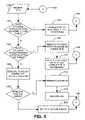
- the generic process executed by the system 60is that illustrated in FIG. 5 .
- the systemimplements the IPSec (Internet Protocol (IP) Security) protocols as defined and explained in the document RFC 2401 (“Security Architecture for the Internet Protocol”) widely available on the Internet and incorporated herein by reference.
- IPInternet Protocol
- RFC 2401Security Architecture for the Internet Protocol
- DTUs originating at a first intranet and destined for a second, remote intranet connected to the first intranet by the Internetare protectively encapsulated.
- this internal DTU with its IP header and IP payloadis placed within another external DTU with its own new IP header.
- This external DTUis provided with an ESP (Encapsulated Security Payload) header and trailer with the internal DTU being placed between these two.
- ESPEncapsulated Security Payload
- the data between these ESP delineatorsis encrypted prior to traversing the Internet. Once received at the second, remote intranet, the protective encapsulation is removed and the data is decrypted to reveal the internal DTU with it's own IP headers and payload.
- the security architecture outlined in RFC 2401uses a number of concepts which must first be explained for a better understanding of the VPN functions of the system.
- the architectureuses, among others, the concepts of an SA (Security Association), and SPD (Security Policy Database), and an SAD (Security Association Database).
- An SAis defined as a one-way connection that provides security to the traffic that travels along the connection. Thus, for a bi-directional VPN link between two intranets, two SAs must be defined—one for each direction.
- An SAis identified by three identifiers—an SPI (Security Parameter Index), an IP Destination Address, and a security protocol identifier.
- the security protocol being used for the VPN functionsis ESP.
- An SADis a database that contains the parameters associated with each active SAs.
- the SPDis a database that contains security policies which will determine the disposition of any incoming or outgoing DTUs.
- Each security policy entrycontains selector values that define the set of IP traffic to which the security policy entry applies. Thus, each policy entry will contain an identification of whether IP traffic to which the policy entry applies will be discarded, be processed using IPSec, or will bypass further processing. If the IP traffic is to be processed, the entry will also contain at least one SA Specification which will list the protocols, mode, and algorithms which will be used.
- Selectorsare sets of IP and upper layer protocol field values that are used by the SPD to match traffic (DTUs) to a specific policy and hence to a specific SA or group of SAs.
- Any incoming DTUs on a VPN linkwill, according to RFC 2401, be processed by the following steps:
- Step 1is performed by the flow engine modules
- Step 2is also performed by a flow engine module.
- the databasesare stored in the system memory. After extracting the relevant data from the external DTU reassembled in step 1, the flow engine module checks the SAD in the system memory.
- Step 3is performed by a combination of modules.
- the flow engine modulecreates a header containing the relevant SA parameters retrieved from the SAD in step 2. This header and the external DTU reassembled in step 1 are then forwarded to the crypto engine module through the switch module.
- the crypto engine moduleusing the SA parameters in the header, authenticates the external DTU and decrypts the payload (the internal DTU) of the external DTU.
- the decrypted DTUis forwarded by the crypto engine module back to the relevant flow engine module using the switch module.
- Step 4is performed by the flow engine module after receiving the decrypted DTU from the crypto engine module.
- Step 5is again performed by the flow engine module. After step 5 is passed, flow engine module then forwards the internal DTU decrypted from the external DTU to the intranet.
- Step 1is executed by the flow engine module that receives the outgoing internal DTU from the local intranet.
- the searching in step 2is, again, executed by the flow engine module.
- the flow engine moduleforwards the outgoing internal DTU to the policy engine module by way of the switch module.
- the policy engine modulethen creates the appropriate SA group and returns the outgoing internal DTU to the relevant flow engine module, again by the way of the switch module.
- the flow engine modulecreates a header containing the relevant SA information associated with the outgoing internal DTU. This header and the outgoing internal DTU are then forwarded to the crypto engine module for encryption and authentication.
- the crypto engine moduleencrypts the outgoing internal DTU pursuant to the SA information in the header.
- the encrypted internal DTUis then transformed into an outgoing external DTU with an appropriate ESP header and trailer and new IP header.
- the outgoing external DTUis forwarded using the switch module, to the relevant flow engine module. This flow engine module then sends out the external DTU to the second remote intranet.
- the processbegins at step 110 with a DTU being received by a flow engine.
- the DTUis then checked against entries in the flow table (Step 120 ) to determine if the DTU is expected. This involves determining if the characteristics of the DTU correspond with at least one entry in the flow table. If there is a match, then the DTU is forwarded to the next processing destination by way of the switch module (step 130 ).
- This next processing destinationcan be another flow engine module, or another internal module such as an encryption module.
- Connector A 140then moves the logic flow back to step 110 to receive another DTU.
- step 150checks the received DTU against entries in the listening table in much the same manner as in step 120 . If the decision in step 150 (determining if the characteristics of the received DTU match an entry in the listening table) is positive, then step 160 is executed This step involves sending the received DTU to the policy engine module for further checking if required. It is quite likely that a connection will be established. The establishment of a connection includes the creation of flow table entry to manage subsequently received DTUs on the connection. Connector A 140 then moves the logic flow back to step 110 .
- step 180is that of forwarding the DTU to the policy engine module for further checking and processing against configured security policies. This checking will determine if the DTU is acceptable or not based on the configured security policies. Decision 190 determines if the DTU is to be allowed access or not based on the checking done in step 180 .
- step 190If the decision in step 190 is positive (i.e. the DTU is to be allowed access), a flow table entry corresponding to the characteristics of the received DTU (step 200 ) is inserted into the flow table. Thus, any succeeding DTUs with the same characteristic will be allowed access based on the new flow table entry. The logic flow then moves to connector A 140 which returns the flow to step 110 .
- step 190If the decision in step 190 is negative and the received DTU is unacceptable based on the configured security policies in the policy engine module, then a log entry is generated (step 210 ) and the offending DTU is discarded (step 220 ). The logic flow then continues to connector A 140 to return to step 110 .
- step 160while only noting the forwarding of the received DTU to the policy engine, involves other steps such as security checks performed on the received DTU according to the security policies enforced by the policy engine.
- step 130that of forwarding the received DTU to its eventual destination, may involve a network address translation performed by the flow engine and, if configured to do so, error checking functions performed on the received DTU.
- an ICintegrated circuit
- half of the policy engine module(the content transfer engine for transferring data) is on a single IC with half of the flow engine (the DTU transfer engine portion) and the switch module.
- the content control processor for the policy engine and the DTU control processor of the flow engine and the cryptographic engineare in separate Integrated Circuits or processors.
- FIG. 7An alternative to the architecture in FIG. 6 is that illustrated in FIG. 7 .
- a monolithic ICis used which contains all components of the policy engine module 90 , switch module 80 , cryptographic engine 100 , and flow engine module 70 .
- the switch modulehas a number of requirements.
- the switch moduleis ideally capable of rapid movement of data streams in this system without any CPU involvement.
- the switch moduleto handle the application proxy functions of the system along with its other functions as a TCP circuit gateway and as a TCP offload, ideally can handle continuous byte streams.
- Delineated packetswould ideally also be something that the switch module can handle as they are used in forwarding packet flows from ingress flow engine modules to egress flow engine modules and in forwarding DTUs with pre-pended headers to the cryptographic engine module for processing.
- the flow engine modulesmay be implemented as specialized hardware to speed up repetitive functions and as a general CPU to assist in orchestrating the hardware functions.
- the policy engine moduleis best implemented as a general purpose CPU with hardware assist for tasks such as pattern matching for content filtering, virus scanning and for scanning for keywords as an application layer proxy.
- the policy engine modulemay also use the TCP protocol offload capability of the flow engine modules for application layer proxy applications and for communicating with outside servers for authentication/authorization content filtering, and virus scanning. External chips may also be used to assist in the computations required for the key exchange process outlined above.
Landscapes
- Engineering & Computer Science (AREA)
- Computer Hardware Design (AREA)
- Computer Security & Cryptography (AREA)
- Computing Systems (AREA)
- General Engineering & Computer Science (AREA)
- Computer Networks & Wireless Communication (AREA)
- Signal Processing (AREA)
- Data Exchanges In Wide-Area Networks (AREA)
- Computer And Data Communications (AREA)
Abstract
Description
- a) receiving an incoming DTU;
- b) determining if said incoming DTU has characteristics which match at least one set of criteria;
- c) in the event said characteristics of said incoming DTU match said at least one set of criteria, forwarding said incoming DTU to a separate component of the device for further processing;
- d) in the event said characteristics of said incoming DTU does not match said at least one set of criteria, forwarding said incoming DTU to a policy engine module for further checking wherein said method is executed by a system comprising:
- the policy engine module for enforcing security policies for said network and for inserting and deleting entries in at least one flow table and in at least one listening table;
- at least one flow engine module for receiving data transmission units (DTUs) from sources external to said system and for forwarding said DTUs to destinations external to said system; and
- a switch module for routing DTUs between different modules in said system wherein
- said switch module is coupled to each one of the other modules in the system;
- said flow engine module receives and forwards DTUs if said DTUs match an entry in either said flow table or said listening table.
- a policy engine module for enforcing security policies for said network and for inserting entries in at least one flow table and in at least one listening table;
- at least one flow engine module for receiving data transmission units (DTUs) from sources external to said system and for forwarding said DTUs to destinations external to said system;
- a switch module for routing DTUs between different modules in said system wherein
- said switch module is coupled to each one of the other modules in the system;
- said flow engine module receives and forwards DTUs if said DTUs match an entry in either said flow table or said listening table.
- a) receiving an incoming DTU at a flow engine module;
- b) checking at least one table for a match between characteristics of expected DTUs and characteristics of said incoming DTU, said at least one table containing entries listing characteristics of expected DTUs;
- c) in the event that a match is found, forwarding said incoming DTU to a module chosen from a group comprising:
- another flow engine module for forwarding said incoming DTU to a destination;
- a cryptographic engine module for decrypting or encrypting said incoming DTU; and
- a policy engine module for checking said incoming DTU
- d) in the event a match is not found, forwarding said incoming DTU to the policy engine module for checking said incoming DTUs against predetermined criteria.
- at least one policy engine module for enforcing security policies of a first network against data traffic coming from and going to at least one second network, said at least one policy engine module inserts and deletes entries in at least one flow table and at least one listening table;
- at least one flow engine module for receiving said data traffic from said at least one second network and for transmitting said data traffic to said at least one second network; and
- a switch module for forwarding relevant data traffic between modules internal to said device;
wherein said switch module is coupled to each one of the other modules in the device and the or each of said flow engine modules receives and forwards said data traffic if said data traffic matches entries in said at least one flow table or in said at least one listening table.
<i, TCP, 207.61.132.17, 80, 10.10.1.210, 1047>
where the table fields denote the following:
| network interface = | I | ||
| protocol used = | TCP | ||
| destination address = | 207.61.132.17 | ||
| destination port = | 80 | ||
| source addresses = | 10.10.1.210 | ||
| source port = | 1047. | ||
The format can therefore be the following:
<[network interface], [protocol], [destination address], [destination port], [source address], [source port]>
<[network interface], [protocol], [destination address], [destination port]>
- 1) Policy Engine sets up an entry in the listening table with the following parameters:
| Protocol = | TCP | ||
| destination address = | Web Server external public address | ||
| (eg 216.188.92.3) | |||
| destination port = | 80 | ||
| network interface = | Internet | ||
| table entry = | <TCP, Web Server external address, 80, | ||
| Internet> | |||
- 2) A flow engine receives a TCP SYNC DTU on the Internet Network Interface with the following characteristics:
| destination address = | Web Server external address (e.g | ||
| 216.188.92.3) | |||
| Destination port = | 80 | ||
| Source address = | client address (e.g. 217.85.63.2) | ||
| source port = | client port number | ||
- 3) The flow engine sends an acknowledgement of the SYN DTU (a SYN ACK DTU is sent)
- 4) The flow engine receives an acknowledgement of the SYN ACK DTU.
- 5) This an indication to the policy engine that a connection it is expecting is now open. (There should now be a flow table entry with parameters indicated in
step 2 on the Internet Network Interface. The mechanism of creating the entry is implementation-dependent. This flow table entry is for data flow going towards the Web Server from the Internet.) - 6) The policy engine requests a connection to the Web Server behind the firewall with the following parameters:
<TCP, dest-IP=Web Server private addr, dst-port=80, source IP=client addr, source port=client port #, network interface=system interface to server> - 7) The flow engine sends a SYN DTU (synchronize DTU with the proper parameter) to the Web Server
- 8) The Web Server returns a SYN ACK DTU which is received by the flow engine
- 9) The flow engine sends an ACK DTU to the Web Server
- 10) This indicates that data transfer between the client and the Web Server is now enabled through the firewall system, albeit through the policy engine. Note that at this stage, there is also a new flow table entry with parameters indicated in
step 8 on the Intranet Network Interface. The new flow table entry relates to data flow from the Web Server going towards the Internet. - 11) For optimization, the policy engine can instruct the system such that flow engine(s) can continue on with the data transfer without its involvement.
Steps:
- 1) Policy engine adds an entry in the listening table with an undetermined destination address.
| Protocol = | TCP | ||
| Destination address = | * (unknown) | ||
| Destination port = | 80 | ||
| Network interface = | network interface on the intranet | ||
- 2) A SYN DTU from the intranet is received by the flow engine with the following characteristics:
| destination address = | web server public external address (external |
| to the firewall) | |
| Destination port = | 80 |
| Source address = | intranet client private address |
| Source port = | intranet client port |
| Since this SYN DTU corresponds to the listening table entry set up in | |
- 3) SYN ACK DTU sent to intranet client from flow engine
- 4) ACK DTU received by flow engine from intranet client
- 5) The policy engine is notified that a connection it is expecting is now open.
- 6) The policy engine requests a connection to the destination external web server using the following parameters:
| Protocol = | TCP | ||
| Destination address = | Web Server public external addr | ||
| Destination port = | 80 | ||
| Source address = | intranet client public address | ||
| Source port = | to be assigned by flow engine | ||
| Network interface = | network interface on the Internet | ||
- 7) SYN DTU sent by flow engine using parameters sent by policy engine with an assigned source port number
- 8) SYN ACK DTU received by flow engine to external web server
- 9) ACK DTU sent by flow engine to external web server
- 10) data transfer between web server and intranet client through the firewall system with the data (DTUs) passing through the policy engine is now fully enabled. Both flow table entries are fully in place.
- 11) For optimization, the policy engine can instruct the system such that data transfer between the Web Server and the intranet client with the DTUs only passing through the flow engine and not the policy engine.
Scenario 3: Outgoing TCP Circuit Gateway setup (SeeFIG. 4C for this scenario). Since thesystem 60 is configured to forward to the policy engine any unknown/unrecognized DTUs, any unknown/unrecognized DTU could be a legitimate SYN DTU. These DTUs can be recognized by the policy engine and can be “recycled” or rerouted back to the input port of the flow engine after setting up a listening table entry. The effect of the “recycling” of the DTU would be to provide the system with a DTU it expects. Once the “recycled” DTU has been received again (to correspond to the listening table entry), a similar process to that inscenario 1 is contemplated. The steps for this current scenario are as follows:
Steps: - 1) Policy engine notifies system that it wants to receive any unknown DTUs from the intranet.
- 2) Flow engine receives an unknown DTU from the intranet. This unknown DTU is forwarded to the policy engine for processing.
- 3) The policy engine recognizes the unknown DTU as being a legitimate SYN DTU. The policy engine then inserts an entry in the listening table. The new entry will correspond to the characteristics of the previously unknown DTU as follows:
| Protocol = | TCP | ||
| Destination address = | addr of remote server | ||
| Destination port = | port of remote server | ||
| Network interface = | interface for intranet | ||
- 4) The now identified SYN DTU is then rerouted back to the flow engine which originally received it. This SYN DTU is then routed to the intranet network interface and is therefore treated by the flow engine as a newly arrived DTU.
- 5) Since the SYN DTU matches the entry of the listening table set up specifically for it, the flow engine responds with a SYN ACK.
- 6) The client responds with an ACK DTU.
- 7) The policy engine is notified that the connection it is expecting is now open.
- 8) With the one connection of the TCP circuit gateway open, the policy engine requests setting up a connection to the remote server using the following parameters:
| Protocol = | TCP | ||
| Destination address = | addr of remote server | ||
| Destination port = | port of remote server | ||
| Source address = | intranet client public address | ||
| Source port = | to be assigned by flow engine | ||
- 9) The flow engine sends out a SYN DTU with the parameters specified by the policy engine with a source port assigned.
- 10) A SYN ACK DTU is received by the flow engine
- 11) The flow engine acknowledges the DTU from the remote server with an ACK DTU.
- 12) With the handshaking between the system and the remote server done, data transfer can occur between the intranet client and the remote server, albeit involving the policy engine.
- 13) For optimization, policy server can requests direct data transfer between the two flow engines for subsequent DTUs.
- 1) The policy engine inserts a listening table entry that will match any FTP connection SYN DTU coming from the intranet. The parameters for this entry are:
| Protocol = | TCP | ||
| Destination address = | * (any) | ||
| Destination port = | 21 (the port for FTP connections) | ||
- 2) A SYN DTU is received by the flow engine from an intranet client wishing to establish an FTP connection to an external FTP server.
- 3) The flow engine sends an acknowledgment of the SYN DTU (SYN ACK DTU) to the intranet client.
- 4) An acknowledgment from the intranet client is received by the flow engine (ACK DTU)
- 5) The policy engine is notified that the connection it is expecting (FTP connection from intranet client) is now open.
- 6) With client connection established, the server connection needs to be established. To accomplish this, the policy engine initiates contact with the destination FTP external server by instructing the flow engine to connect with the FTP server. The parameters are as follows:
| Protocol = | TCP | ||
| Destination address = | FTP server address | ||
| Destination port = | 21 | ||
| Source address = | intranet client public address | ||
| Source port = | to be assigned by flow engine | ||
| Network interface = | flow engine interface to Internet | ||
- 7) Following the instructions of the policy engine, the flow engine sends out a SYN DTU with the proper parameters as set out in
step 6 with a properly assigned port number. - 8) A SYN ACK DTU is received by the flow engine from the remote FTP server.
- 9) The flow engine sends an ACK DTU to the remote FTP server.
- 10) Data exchange, with the DTUs containing FTP control information, between the remote FTP sever and the intranet client through the policy server is now fully enabled. The data (control info) passes through the policy engine which checks for FTP commands such as PORT, PASV, RTRV, STOR.
- 7) Following the instructions of the policy engine, the flow engine sends out a SYN DTU with the proper parameters as set out in
- 1) The intranet client issues a PORT command carried in a data DTU intended for the FTP external server but received by the flow engine and the policy engine. The PORT command will contain the private address of an intranet client and port number which will receive data from the external FTP server.
- 2) The policy engine then inserts a flow table entry that will match any incoming DTUs from the external FTP server for this specific connection. The parameters for this entry are:
| Protocol = | TCP | ||
| Destination address = | intranet client public address | ||
| Destination port = | to be assigned by the flow engine | ||
| Source address = | FTP server address | ||
| Source port = | 21 | ||
| Network interface = | network interface on Internet | ||
- 3) The policy engine modifies the PORT command parameters as follows:
- destination address: intranet client public address, destination port: port assigned by the flow engine in
step 2. The DTU containing the (modified) PORT command is then allowed to proceed to the destination server through the flow engine.
- destination address: intranet client public address, destination port: port assigned by the flow engine in
- 4) a RTRV or STOR type command (to retrieve data from or store data to the FTP server) is then transmitted, by way of the flow engine and the policy engine, to the FTP server. This type of command will trigger the remote FTP server to set up the data connection.
- 5) Once the command in
step 4 is received by the FTP server, the FTP server initiates a handshaking sequence. This is started by the flow engine receiving a SYN DTU from the FTP server with the following parameters:
- 3) The policy engine modifies the PORT command parameters as follows:
| Destination address = | intranet client public address |
| Destination port = | assigned port by flow engine in |
| Source address = | FTP server address |
| Source port = | 21 (default, server may use dynamic port number) |
- 6) The flow engine, as part of the 3 part handshaking process, sends a SYN ACK DTU to the remote FTP server.
- 7) The FTP server responds with and ACK DTU to the flow engine.
- 8) A connection to the policy engine from the FTP server is opened.
- 9) The policy engine requests a connection to the intranet client with the following parameters:
| Protocol = | TCP |
| Destination address = | data IP address in PORT command in |
| Destination port = | data IP port in PORT command in |
| Source address = | FTP server address |
| Source port = | 21 |
| Network interface = | network interface on Intranet. |
- 10) To establish the connection to the intranet client, the flow engine sends a SYN DTU to the intranet client as part of a handshaking procedure.
- 11) A SYN ACK DTU is then received by the flow engine from the intranet client.
- 12) An ACK DTU is sent by the flow engine in response to the SYN ACK DTU.
- 13) With the handshaking procedure complete, FTP data transfer can now proceed via the policy engine.
- 14) For optimization, the policy engine can instruct the system to undergo data transfer without the policy engine's involvement, if appropriate.
Steps:
- 1) The policy engine inserts an entry into the listening table. The parameters of the entry are:
| Protocol: | UDP | ||
| Destination address: | configured remote address (the known | ||
| address of the remote server) | |||
| Destination port: | configured port for the remote address | ||
| Network interface: | network interface to | ||
- 2) The flow engine receives a datagram/DTU from
NETWORK 1 that matches the listening table entry inserted instep 1. - 3) The policy engine receives the datagram/DTU from the flow engine. (At this stage, a new flow entry matching the parameters in
step 2 should be in place forNetwork 1,) - 4) The policy engine requests setting up a “connection” to the remote server with the following parameters:
- 2) The flow engine receives a datagram/DTU from
| Protocol: | UDP | ||
| Destination address: | configured remote address | ||
| Destination port: | configured port for the remote address | ||
| Source address: | address of the | ||
| sent the datagram/DTU | |||
| Source port: | port number for the | ||
| Network interface: | network interface for NETWORK 2 | ||
| (At this stage, a new flow entry matching the parameters in | |||
- 5) The policy engine requests sending the datagram received in
step 3. - 6) The datagram/DTU is sent by the flow engine to the remote server.
- 7) With the communication between the client and server enabled through the firewall system albeit through the policy engine, the policy engine can request the system to optimize the data transfer: any subsequent datagram/DTUs sent between the two ends of the “connection” are handled without the intervention of the policy engine. Such a transfer scheme would provide faster, more efficient communications between the two ends of the connection.
- 5) The policy engine requests sending the datagram received in
- 1) The policy engine inserts an entry into the listening table with the following parameters:
| Protocol: | UDP | ||
| destination address: | * (Unknown—unspecified) | ||
| Destination port: | configured port number | ||
| Network interface: | network interface on | ||
- 2) The flow engine receives a UDP datagram/DTU from
NETWORK 1 that matches the entry in the listening table inserted instep 1 above. - 3) The flow engine notifies the policy engine of the UDP datagram/DTU received. (At this stage, a new flow table entry matching the parameters in
step 2 should be in place. The implementation of table entry creation can be via automatic creation on reception of a packet matching the listening table entry, or viastep 4 below). - 4) The policy engine then requests a “connection” to the
NETWORK 1 source of the UDP datagram/DTU. This has the effect of setting up a flow table entry. The parameters are:
- 2) The flow engine receives a UDP datagram/DTU from
| Protocol: | UDP | ||
| Destination address: | |||
| Destination port: | client port number | ||
| Network interface: | network interface for | ||
| source address: | |||
| source port: | configured port on | ||
- 5) The policy engine then requests a “connection” to the
NETWORK 2 destination of the UDP datagram/DTU received instep 2. This has the effect of setting up a flow table entry. The parameters for the flow table entry are:
- 5) The policy engine then requests a “connection” to the
| Protocol: | UDP | ||
| Destination address: | |||
| Destination port: | configured port on | ||
| source address: | |||
| Source port: | client port on | ||
| Network interface: | network interface for NETWORK 2 | ||
| (At this stage, a new flow table entry on | |||
- 6) The policy engine requests sending the datagram received in
step 3 - 7) Based on the request from the policy engine in
step 6, the flow engine sends the UDP datagram/DTU to theNETWORK 2 server. - 8) As an optimization, any subsequent UDP datagram/DTUs can be handled purely by the flow engine without any intervention from the policy engine.
- 6) The policy engine requests sending the datagram received in
- 1) To be notified of any intranet clients wanting a UDP connection, the policy engine commands the system that any unknown DTUs received from the intranet are to be sent to the policy engine by the flow engine.
- 2) The flow engine receives an unknown DTU from the intranet. This DTU is then forwarded to the policy engine in accordance with
step 1. - 3) The policy engine recognizes the DTU to be a legitimate UDP datagram/DTU and sets up a “connection” for any incoming UDP datagram/DTUs that may be received in the future in response to the received datagram/DTU.
| Protocol: | UDP | ||
| Destination address: | local/private address of intranet client | ||
| Destination port: | port for intranet client | ||
| Source address: | remote address of the Internet server | ||
| Source port: | port for the Internet server | ||
| Network interface: | network interface on Intranet | ||
| Note that the request for connection has the effect of setting up a corresponding flow table entry. | |||
- 4) The “connection” to the Internet server is configured. The policy engine requests a “connection” to be made with the following parameters (This has the effect of sending up a flow table entry):
| Protocol: | UDP | ||
| destination address: | remote address of Internet server | ||
| destination port: | port for remote Internet server | ||
| source addresses: | public address for intranet client (or to be | ||
| assigned) | |||
| Source port: | to be assigned by the flow engine | ||
| Network interface: | network interface on Internet | ||
- 5) With both of the “connections” established, the initial data transfer path (with the policy engine intervening) is now ready.
- 6) This represents the optimized data transfer path, without the policy engine intervention, if the policy engine requests the system to do so.
- 7) Since the data transfer paths are ready and configured, any data transfer can occur. The datagram received by the policy engine in
step 2 is “recycled” back to the intranet interface. Since the relevant table entries were inserted insteps
Scenario 9: Another possible scenario involves dynamic UDP connections. Such connections are used by the popular messaging, video and voice application implemented over the Internet. Such an application can use both proper TCP connections and UDP virtual connections as explained above. For the NetMeeting application, some port numbers are statically assigned while others are dynamically assigned.
- 1) A control DTU with an embedded local address and port number (local-address, local port #) is received by a flow engine from the intranet.
- 2) The policy engine sets up a flow table entry for entering DTUs whose destination is the local address and port number embedded in the control DTU received in
Step 1. The flow table entry characteristics are:
| Protocol: | UDP | ||
| Destination address: | public address of the intranet client | ||
| Destination port: | to be assigned | ||
| Source address: | remote address of the Internet server | ||
| Source port: | port for the Internet server | ||
| Network interface: | network interface on the Internet | ||
- 3) A control message with the translated local address and the translated local port is then sent out to the Internet server.
- 4) A flow table entry for DTUs from the intranet client is then set up by the policy engine. The flow table entry will have the following characteristics:
| Protocol: | UDP | ||
| Destination address: | remote address of the Internet server | ||
| Destination port: | remote port for the Internet server | ||
| Source address: | local address of the intranet client | ||
| Source port: | local port number for the intranet client | ||
| Network interface: | network interface on the intranet | ||
| Data is transferred between the intranet client and the Internet server with the data passing through the policy engine. | |||
- 5) For optimization, subsequent data transfers can be effected without the intervention of the policy engine.
- 1) IP fragments are reassembled into an IP DTU—this step may be required due to the possibility of external DTUs being fragmented for their transport between the first local intranet and the second remote intranet.
- 2) The External DTU's destination address from it's IP header, its IPSec protocol and it's SPI (from the ESP header) are used to find the relevant SA from the SAD.
- 3) Once the SA is found, its parameters are read from the SAD and the external DTU is processed according to the IPSec protocol; this includes decrypting the internal DTU and authenticating the external DTU.
- 4) The SPD is then searched for a security policy entry that matches the internal DTU received.
- 5) A check is then performed determining if the proper IPSec processing has been applied. This is done by verifying that the SA found in
step 2 matches the kind and order of SA's required by the policy found instep 4.
- 1) Match the selector fields of an internal DTU against the outbound security policies in the SPD. The first appropriate policy will point to zero or more SAs or groups of SAs (termed SA bundles in RFC2401) in the SAD.
- 2) Match the selector fields of the internal DTU against the selector fields of the SAs found in
step 1. If no SA matches, then an SA or an SA group is created including inserting an appropriate SAD entry corresponding to the SA or SA group and the SPD entry found instep 1 will be linked to the new SAD entry. If no key management entity is found, the internal DTU is discarded. - 3) The SA group found/created in
step 2 is used to perform the required IPSec processing including authentication and encryption.
Claims (25)
Priority Applications (1)
| Application Number | Priority Date | Filing Date | Title |
|---|---|---|---|
| US10/192,802US7441262B2 (en) | 2002-07-11 | 2002-07-11 | Integrated VPN/firewall system |
Applications Claiming Priority (1)
| Application Number | Priority Date | Filing Date | Title |
|---|---|---|---|
| US10/192,802US7441262B2 (en) | 2002-07-11 | 2002-07-11 | Integrated VPN/firewall system |
Publications (2)
| Publication Number | Publication Date |
|---|---|
| US20040010712A1 US20040010712A1 (en) | 2004-01-15 |
| US7441262B2true US7441262B2 (en) | 2008-10-21 |
Family
ID=30114405
Family Applications (1)
| Application Number | Title | Priority Date | Filing Date |
|---|---|---|---|
| US10/192,802Expired - Fee RelatedUS7441262B2 (en) | 2002-07-11 | 2002-07-11 | Integrated VPN/firewall system |
Country Status (1)
| Country | Link |
|---|---|
| US (1) | US7441262B2 (en) |
Cited By (13)
| Publication number | Priority date | Publication date | Assignee | Title |
|---|---|---|---|---|
| US20050177865A1 (en)* | 2002-09-20 | 2005-08-11 | Matsushita Electric Industrial Co., Ltd. | Control of access by intermediate network element for connecting data communication networks |
| US20070156850A1 (en)* | 2005-12-30 | 2007-07-05 | Intel Corporation | Secure remote access using portable storage device |
| US20090037631A1 (en)* | 2007-07-31 | 2009-02-05 | Viasat, Inc. | Input Output Access Controller |
| US7808897B1 (en)* | 2005-03-01 | 2010-10-05 | International Business Machines Corporation | Fast network security utilizing intrusion prevention systems |
| US20110035578A1 (en)* | 2008-01-17 | 2011-02-10 | Eads Defence And Security Systems Limited | Secure communication system |
| US7899867B1 (en)* | 2002-07-31 | 2011-03-01 | FaceTime Communications, Inc, | SpIM blocking and user approval techniques for real-time messaging networks |
| US20110138455A1 (en)* | 2009-12-09 | 2011-06-09 | Waskiewicz Peter P | Firewall filtering using network controller circuitry |
| US9584587B2 (en)* | 2015-02-03 | 2017-02-28 | Fortinet, Inc. | Managing transmission and storage of sensitive data |
| US10021022B2 (en)* | 2015-06-30 | 2018-07-10 | Juniper Networks, Inc. | Public network address conservation |
| US10505937B2 (en) | 2017-02-01 | 2019-12-10 | Servicenow, Inc. | System and method for application route management |
| US11012473B1 (en)* | 2019-11-01 | 2021-05-18 | EMC IP Holding Company LLC | Security module for auto-generating secure channels |
| US12028207B1 (en) | 2023-05-03 | 2024-07-02 | Bank Of America Corporation | System and method for dynamically aggregating multiple firewall security configurations in a decentralized network |
| US12418509B2 (en) | 2023-05-03 | 2025-09-16 | Bank Of America Corporation | System and method for updating a firewall security configuration in a decentralized network |
Families Citing this family (74)
| Publication number | Priority date | Publication date | Assignee | Title |
|---|---|---|---|---|
| US8539112B2 (en) | 1997-10-14 | 2013-09-17 | Alacritech, Inc. | TCP/IP offload device |
| US8621101B1 (en) | 2000-09-29 | 2013-12-31 | Alacritech, Inc. | Intelligent network storage interface device |
| US8782199B2 (en)* | 1997-10-14 | 2014-07-15 | A-Tech Llc | Parsing a packet header |
| US6434620B1 (en)* | 1998-08-27 | 2002-08-13 | Alacritech, Inc. | TCP/IP offload network interface device |
| US6757746B2 (en)* | 1997-10-14 | 2004-06-29 | Alacritech, Inc. | Obtaining a destination address so that a network interface device can write network data without headers directly into host memory |
| US6226680B1 (en) | 1997-10-14 | 2001-05-01 | Alacritech, Inc. | Intelligent network interface system method for protocol processing |
| US6697868B2 (en)* | 2000-02-28 | 2004-02-24 | Alacritech, Inc. | Protocol processing stack for use with intelligent network interface device |
| US6981278B1 (en)* | 2000-09-05 | 2005-12-27 | Sterling Commerce, Inc. | System and method for secure dual channel communication through a firewall |
| US8019901B2 (en) | 2000-09-29 | 2011-09-13 | Alacritech, Inc. | Intelligent network storage interface system |
| US7543087B2 (en)* | 2002-04-22 | 2009-06-02 | Alacritech, Inc. | Freeing transmit memory on a network interface device prior to receiving an acknowledgement that transmit data has been received by a remote device |
| US20100138909A1 (en)* | 2002-09-06 | 2010-06-03 | O2Micro, Inc. | Vpn and firewall integrated system |
| JP2004104280A (en)* | 2002-09-06 | 2004-04-02 | Yamatake Corp | Interface device for monitoring encrypted networks |
| GB2397204B (en)* | 2002-09-06 | 2005-03-30 | O2Micro Inc | VPN and firewall integrated system |
| WO2004036834A1 (en)* | 2002-10-17 | 2004-04-29 | Nokia Corporation | Secured virtual private network with mobile nodes |
| US7660980B2 (en)* | 2002-11-18 | 2010-02-09 | Liquidware Labs, Inc. | Establishing secure TCP/IP communications using embedded IDs |
| US7386889B2 (en)* | 2002-11-18 | 2008-06-10 | Trusted Network Technologies, Inc. | System and method for intrusion prevention in a communications network |
| MY141160A (en)* | 2003-01-13 | 2010-03-31 | Multimedia Glory Sdn Bhd | System and method of preventing the transmission of known and unknown electronic content to and from servers or workstations connected to a common network |
| US20040162996A1 (en)* | 2003-02-18 | 2004-08-19 | Nortel Networks Limited | Distributed security for industrial networks |
| US7346700B2 (en)* | 2003-04-07 | 2008-03-18 | Time Warner Cable, A Division Of Time Warner Entertainment Company, L.P. | System and method for managing e-mail message traffic |
| US7409712B1 (en)* | 2003-07-16 | 2008-08-05 | Cisco Technology, Inc. | Methods and apparatus for network message traffic redirection |
| US6996070B2 (en)* | 2003-12-05 | 2006-02-07 | Alacritech, Inc. | TCP/IP offload device with reduced sequential processing |
| US7797752B1 (en)* | 2003-12-17 | 2010-09-14 | Vimal Vaidya | Method and apparatus to secure a computing environment |
| US20060064469A1 (en)* | 2004-09-23 | 2006-03-23 | Cisco Technology, Inc. | System and method for URL filtering in a firewall |
| US8146145B2 (en)* | 2004-09-30 | 2012-03-27 | Rockstar Bidco Lp | Method and apparatus for enabling enhanced control of traffic propagation through a network firewall |
| US7660798B1 (en)* | 2004-10-04 | 2010-02-09 | Adobe Systems Incorporated | System and method for providing document security, access control and automatic identification of recipients |
| US8248939B1 (en)* | 2004-10-08 | 2012-08-21 | Alacritech, Inc. | Transferring control of TCP connections between hierarchy of processing mechanisms |
| AU2005328336B2 (en)* | 2004-12-22 | 2011-09-15 | Wake Forest University | Method, systems, and computer program products for implementing function-parallel network firewall |
| EP1864226B1 (en)* | 2005-03-28 | 2013-05-15 | Wake Forest University | Methods, systems, and computer program products for network firewall policy optimization |
| US7634584B2 (en) | 2005-04-27 | 2009-12-15 | Solarflare Communications, Inc. | Packet validation in virtual network interface architecture |
| US8656191B2 (en) | 2005-12-23 | 2014-02-18 | Nagravision S.A. | Secure system-on-chip |
| EP1811415A1 (en)* | 2005-12-23 | 2007-07-25 | Nagracard S.A. | Secure system-on-chip |
| EP1802030A1 (en)* | 2005-12-23 | 2007-06-27 | Nagracard S.A. | Secure system-on-chip |
| US20080263171A1 (en)* | 2007-04-19 | 2008-10-23 | Alacritech, Inc. | Peripheral device that DMAS the same data to different locations in a computer |
| US20090099427A1 (en)* | 2007-10-12 | 2009-04-16 | Arkal Medical, Inc. | Microneedle array with diverse needle configurations |
| US20090199290A1 (en)* | 2008-02-01 | 2009-08-06 | Secure Computing Corporation | Virtual private network system and method |
| US8539513B1 (en) | 2008-04-01 | 2013-09-17 | Alacritech, Inc. | Accelerating data transfer in a virtual computer system with tightly coupled TCP connections |
| US8341286B1 (en) | 2008-07-31 | 2012-12-25 | Alacritech, Inc. | TCP offload send optimization |
| US9306793B1 (en) | 2008-10-22 | 2016-04-05 | Alacritech, Inc. | TCP offload device that batches session layer headers to reduce interrupts as well as CPU copies |
| US20100268935A1 (en)* | 2009-04-21 | 2010-10-21 | Richard Rodgers | Methods, systems, and computer readable media for maintaining flow affinity to internet protocol security (ipsec) sessions in a load-sharing security gateway |
| US8495725B2 (en) | 2009-08-28 | 2013-07-23 | Great Wall Systems | Methods, systems, and computer readable media for adaptive packet filtering |
| DE102010041804A1 (en) | 2010-09-30 | 2012-04-05 | Siemens Aktiengesellschaft | Method for secure data transmission with a VPN box |
| KR101472695B1 (en) | 2010-10-15 | 2014-12-12 | 닛본 덴끼 가부시끼가이샤 | Switching system, and monitoring centralization management method |
| JP5621639B2 (en)* | 2011-02-08 | 2014-11-12 | 村田機械株式会社 | Relay server and relay communication system |
| US20130318084A1 (en)* | 2012-05-22 | 2013-11-28 | Xockets IP, LLC | Processing structured and unstructured data using offload processors |
| US10129182B2 (en)* | 2012-06-29 | 2018-11-13 | Juniper Networks, Inc. | Methods and apparatus for providing services in distributed switch |
| US9565213B2 (en) | 2012-10-22 | 2017-02-07 | Centripetal Networks, Inc. | Methods and systems for protecting a secured network |
| US9137205B2 (en) | 2012-10-22 | 2015-09-15 | Centripetal Networks, Inc. | Methods and systems for protecting a secured network |
| US9203806B2 (en) | 2013-01-11 | 2015-12-01 | Centripetal Networks, Inc. | Rule swapping in a packet network |
| US9124552B2 (en) | 2013-03-12 | 2015-09-01 | Centripetal Networks, Inc. | Filtering network data transfers |
| US9094445B2 (en) | 2013-03-15 | 2015-07-28 | Centripetal Networks, Inc. | Protecting networks from cyber attacks and overloading |
| US10742604B2 (en)* | 2013-04-08 | 2020-08-11 | Xilinx, Inc. | Locked down network interface |
| US9426124B2 (en) | 2013-04-08 | 2016-08-23 | Solarflare Communications, Inc. | Locked down network interface |
| US9479437B1 (en)* | 2013-12-20 | 2016-10-25 | Google Inc. | Efficient updates of weighted cost multipath (WCMP) groups |
| EP2942925B1 (en)* | 2014-05-05 | 2016-08-24 | Advanced Digital Broadcast S.A. | A method and system for providing a private network |
| US9264370B1 (en) | 2015-02-10 | 2016-02-16 | Centripetal Networks, Inc. | Correlating packets in communications networks |
| US9807117B2 (en) | 2015-03-17 | 2017-10-31 | Solarflare Communications, Inc. | System and apparatus for providing network security |
| US9866576B2 (en)* | 2015-04-17 | 2018-01-09 | Centripetal Networks, Inc. | Rule-based network-threat detection |
| US9917856B2 (en) | 2015-12-23 | 2018-03-13 | Centripetal Networks, Inc. | Rule-based network-threat detection for encrypted communications |
| US11729144B2 (en) | 2016-01-04 | 2023-08-15 | Centripetal Networks, Llc | Efficient packet capture for cyber threat analysis |
| EP3310015A1 (en)* | 2016-10-11 | 2018-04-18 | Secucloud GmbH | Network filtering using router connection data |
| US10594732B2 (en)* | 2016-11-08 | 2020-03-17 | Ca, Inc. | Selective traffic blockage |
| US10503899B2 (en) | 2017-07-10 | 2019-12-10 | Centripetal Networks, Inc. | Cyberanalysis workflow acceleration |
| US11233777B2 (en) | 2017-07-24 | 2022-01-25 | Centripetal Networks, Inc. | Efficient SSL/TLS proxy |
| US10284526B2 (en) | 2017-07-24 | 2019-05-07 | Centripetal Networks, Inc. | Efficient SSL/TLS proxy |
| US11165720B2 (en) | 2017-12-19 | 2021-11-02 | Xilinx, Inc. | Network interface device |
| US10686731B2 (en) | 2017-12-19 | 2020-06-16 | Xilinx, Inc. | Network interface device |
| US10686872B2 (en) | 2017-12-19 | 2020-06-16 | Xilinx, Inc. | Network interface device |
| US10333898B1 (en) | 2018-07-09 | 2019-06-25 | Centripetal Networks, Inc. | Methods and systems for efficient network protection |
| US10659555B2 (en) | 2018-07-17 | 2020-05-19 | Xilinx, Inc. | Network interface device and host processing device |
| US10838763B2 (en) | 2018-07-17 | 2020-11-17 | Xilinx, Inc. | Network interface device and host processing device |
| US11362996B2 (en) | 2020-10-27 | 2022-06-14 | Centripetal Networks, Inc. | Methods and systems for efficient adaptive logging of cyber threat incidents |
| US11677717B2 (en)* | 2021-03-22 | 2023-06-13 | Cloudflare, Inc. | Unified network service that connects multiple disparate private networks and end user client devices operating on separate networks |
| US11159546B1 (en) | 2021-04-20 | 2021-10-26 | Centripetal Networks, Inc. | Methods and systems for efficient threat context-aware packet filtering for network protection |
| CN114401149B (en)* | 2022-01-30 | 2022-09-06 | 杭州立思辰安科科技有限公司 | Method, system, equipment and storage medium for processing protocol dynamic port in firewall network card load balancing mechanism |
Citations (13)
| Publication number | Priority date | Publication date | Assignee | Title |
|---|---|---|---|---|
| US6219786B1 (en)* | 1998-09-09 | 2001-04-17 | Surfcontrol, Inc. | Method and system for monitoring and controlling network access |
| US20020191604A1 (en)* | 2001-05-02 | 2002-12-19 | Mitchell Oscar R. | Application-specific information-processing method, system, and apparatus |
| US20030110274A1 (en)* | 2001-08-30 | 2003-06-12 | Riverhead Networks Inc. | Protecting against distributed denial of service attacks |
| US20030145227A1 (en)* | 2002-01-28 | 2003-07-31 | International Business Machines Corporation | System and method of automatically handling internet key exchange traffic in a virtual private network |
| US20030154399A1 (en)* | 2002-02-08 | 2003-08-14 | Nir Zuk | Multi-method gateway-based network security systems and methods |
| US20030172264A1 (en)* | 2002-01-28 | 2003-09-11 | Hughes Electronics | Method and system for providing security in performance enhanced network |
| US6636898B1 (en)* | 1999-01-29 | 2003-10-21 | International Business Machines Corporation | System and method for central management of connections in a virtual private network |
| US20040117653A1 (en)* | 2001-07-10 | 2004-06-17 | Packet Technologies Ltd. | Virtual private network mechanism incorporating security association processor |
| US6754832B1 (en)* | 1999-08-12 | 2004-06-22 | International Business Machines Corporation | Security rule database searching in a network security environment |
| US6781990B1 (en)* | 2002-02-11 | 2004-08-24 | Extreme Networks | Method and system for managing traffic in a packet network environment |
| US6928553B2 (en)* | 2001-09-18 | 2005-08-09 | Aastra Technologies Limited | Providing internet protocol (IP) security |
| US6957274B2 (en)* | 2001-06-27 | 2005-10-18 | Microsoft Corporation | System adds additional new routes and default routes to a routing table to allow concurrent access to two different network connections |
| US7028332B1 (en)* | 2000-06-13 | 2006-04-11 | Intel Corporation | Method and apparatus for preventing packet retransmissions during IPsec security association establishment |
- 2002
- 2002-07-11USUS10/192,802patent/US7441262B2/ennot_activeExpired - Fee Related
Patent Citations (13)
| Publication number | Priority date | Publication date | Assignee | Title |
|---|---|---|---|---|
| US6219786B1 (en)* | 1998-09-09 | 2001-04-17 | Surfcontrol, Inc. | Method and system for monitoring and controlling network access |
| US6636898B1 (en)* | 1999-01-29 | 2003-10-21 | International Business Machines Corporation | System and method for central management of connections in a virtual private network |
| US6754832B1 (en)* | 1999-08-12 | 2004-06-22 | International Business Machines Corporation | Security rule database searching in a network security environment |
| US7028332B1 (en)* | 2000-06-13 | 2006-04-11 | Intel Corporation | Method and apparatus for preventing packet retransmissions during IPsec security association establishment |
| US20020191604A1 (en)* | 2001-05-02 | 2002-12-19 | Mitchell Oscar R. | Application-specific information-processing method, system, and apparatus |
| US6957274B2 (en)* | 2001-06-27 | 2005-10-18 | Microsoft Corporation | System adds additional new routes and default routes to a routing table to allow concurrent access to two different network connections |
| US20040117653A1 (en)* | 2001-07-10 | 2004-06-17 | Packet Technologies Ltd. | Virtual private network mechanism incorporating security association processor |
| US20030110274A1 (en)* | 2001-08-30 | 2003-06-12 | Riverhead Networks Inc. | Protecting against distributed denial of service attacks |
| US6928553B2 (en)* | 2001-09-18 | 2005-08-09 | Aastra Technologies Limited | Providing internet protocol (IP) security |
| US20030145227A1 (en)* | 2002-01-28 | 2003-07-31 | International Business Machines Corporation | System and method of automatically handling internet key exchange traffic in a virtual private network |
| US20030172264A1 (en)* | 2002-01-28 | 2003-09-11 | Hughes Electronics | Method and system for providing security in performance enhanced network |
| US20030154399A1 (en)* | 2002-02-08 | 2003-08-14 | Nir Zuk | Multi-method gateway-based network security systems and methods |
| US6781990B1 (en)* | 2002-02-11 | 2004-08-24 | Extreme Networks | Method and system for managing traffic in a packet network environment |
Non-Patent Citations (6)
| Title |
|---|
| Kent & Atkinson, Standards Track "Security Architecture for the Internet Protocol" Network Working Group, The Internet Society, Nov. 1998, pp. 1-66. |
| NetScreen "Products" http://www.netscreen.com/products/datasheets.html. |
| NetScreen "Solutions" http://www.netscreen.com/solutions/index.html. |
| NetScreen, "High Performance Firewall, VPN, and traffic shaping" http://www.netscreen.com/main.html. |
| RapidStream, Inc.-Offering High Performance, ASIC based, VPN, Firewall http://www.rapidstream.com/. |
| William Stallings et al., "IP Security", Mar. 2000, pp. 11-26, Internet Protocol Journal, vol. 3, No. 1.* |
Cited By (22)
| Publication number | Priority date | Publication date | Assignee | Title |
|---|---|---|---|---|
| US7899867B1 (en)* | 2002-07-31 | 2011-03-01 | FaceTime Communications, Inc, | SpIM blocking and user approval techniques for real-time messaging networks |
| US7784084B2 (en)* | 2002-09-20 | 2010-08-24 | Panasonic Corporation | Access control at an intermediate network element connecting a plurality of data communications networks |
| US20050177865A1 (en)* | 2002-09-20 | 2005-08-11 | Matsushita Electric Industrial Co., Ltd. | Control of access by intermediate network element for connecting data communication networks |
| US7808897B1 (en)* | 2005-03-01 | 2010-10-05 | International Business Machines Corporation | Fast network security utilizing intrusion prevention systems |
| US20070156850A1 (en)* | 2005-12-30 | 2007-07-05 | Intel Corporation | Secure remote access using portable storage device |
| US8312292B2 (en) | 2007-07-31 | 2012-11-13 | Viasat, Inc. | Input output access controller |
| US20090037631A1 (en)* | 2007-07-31 | 2009-02-05 | Viasat, Inc. | Input Output Access Controller |
| US20090158050A1 (en)* | 2007-07-31 | 2009-06-18 | Viasat, Inc. | Trusted Labeler |
| US20090034734A1 (en)* | 2007-07-31 | 2009-02-05 | Viasat, Inc. | Multi-Level Key Manager |
| US8392983B2 (en)* | 2007-07-31 | 2013-03-05 | Viasat, Inc. | Trusted labeler |
| US9781076B2 (en)* | 2008-01-17 | 2017-10-03 | Cassidian Limited | Secure communication system |
| US20110035578A1 (en)* | 2008-01-17 | 2011-02-10 | Eads Defence And Security Systems Limited | Secure communication system |
| US20110138455A1 (en)* | 2009-12-09 | 2011-06-09 | Waskiewicz Peter P | Firewall filtering using network controller circuitry |
| US8555368B2 (en)* | 2009-12-09 | 2013-10-08 | Intel Corporation | Firewall filtering using network controller circuitry |
| US9584587B2 (en)* | 2015-02-03 | 2017-02-28 | Fortinet, Inc. | Managing transmission and storage of sensitive data |
| US9826023B2 (en) | 2015-02-03 | 2017-11-21 | Fortinet, Inc. | Managing transmission and storage of sensitive data |
| US10382525B2 (en) | 2015-02-03 | 2019-08-13 | Fortinet, Inc. | Managing transmission and storage of sensitive data |
| US10021022B2 (en)* | 2015-06-30 | 2018-07-10 | Juniper Networks, Inc. | Public network address conservation |
| US10505937B2 (en) | 2017-02-01 | 2019-12-10 | Servicenow, Inc. | System and method for application route management |
| US11012473B1 (en)* | 2019-11-01 | 2021-05-18 | EMC IP Holding Company LLC | Security module for auto-generating secure channels |
| US12028207B1 (en) | 2023-05-03 | 2024-07-02 | Bank Of America Corporation | System and method for dynamically aggregating multiple firewall security configurations in a decentralized network |
| US12418509B2 (en) | 2023-05-03 | 2025-09-16 | Bank Of America Corporation | System and method for updating a firewall security configuration in a decentralized network |
Also Published As
| Publication number | Publication date |
|---|---|
| US20040010712A1 (en) | 2004-01-15 |
Similar Documents
| Publication | Publication Date | Title |
|---|---|---|
| US7441262B2 (en) | Integrated VPN/firewall system | |
| US7823194B2 (en) | System and methods for identification and tracking of user and/or source initiating communication in a computer network | |
| US7536715B2 (en) | Distributed firewall system and method | |
| US7051365B1 (en) | Method and apparatus for a distributed firewall | |
| US9350715B1 (en) | Methods and apparatus for network communications via a transparent security proxy | |
| JP2023535304A (en) | Encrypted SNI filtering method and system for cybersecurity applications | |
| Bellovin | Distributed firewalls | |
| US6003084A (en) | Secure network proxy for connecting entities | |
| US7376134B2 (en) | Privileged network routing | |
| US7086086B2 (en) | System and method for maintaining N number of simultaneous cryptographic sessions using a distributed computing environment | |
| US7657940B2 (en) | System for SSL re-encryption after load balance | |
| EP2823620B1 (en) | Enhancing ipsec performance and security against eavesdropping | |
| US20080141020A1 (en) | Method and Apparatus for Providing Secure Streaming Data Transmission Facilities Using Unreliable Protocols | |
| US20020069356A1 (en) | Integrated security gateway apparatus | |
| US20080130900A1 (en) | Method and apparatus for providing secure communication | |
| JP2005503699A (en) | System and method for host-based security in a computer network | |
| JP2005503047A (en) | Apparatus and method for providing a secure network | |
| JPH11167537A (en) | Fire wall service supply method | |
| WO2010124014A2 (en) | Methods, systems, and computer readable media for maintaining flow affinity to internet protocol security (ipsec) sessions in a load-sharing security gateway | |
| EP1574009B1 (en) | Systems and apparatuses using identification data in network communication | |
| GB2317792A (en) | Virtual Private Network for encrypted firewall | |
| Keromytis et al. | Transparent Network Security Policy Enforcement. | |
| Hohendorf et al. | Secure End-to-End Transport Over SCTP. | |
| Cisco | Configuring IPSec Network Security | |
| EP1290852A2 (en) | Distributed firewall system and method |
Legal Events
| Date | Code | Title | Description |
|---|---|---|---|
| AS | Assignment | Owner name:SEAWAY NETWORKS INC., CANADA Free format text:ASSIGNMENT OF ASSIGNORS INTEREST;ASSIGNORS:HUI, MAN HIM;LAPP, DAVID PHILIP;REEL/FRAME:013100/0402 Effective date:20020704 | |
| AS | Assignment | Owner name:FREESCALE SEMICONDUCTOR, INC., TEXAS Free format text:ASSIGNMENT OF ASSIGNORS INTEREST;ASSIGNORS:SEAWAY NETWORKS (DELAWARE) INCORPORATED;SEAWAY NETWORKS INC.;REEL/FRAME:016998/0720 Effective date:20050819 | |
| AS | Assignment | Owner name:FREESCALE SEMICONDUCTOR, INC., TEXAS Free format text:ASSIGNMENT OF ASSIGNORS INTEREST;ASSIGNOR:SEAWAY NETWORKS INCORPORATED;REEL/FRAME:017645/0433 Effective date:20050819 | |
| AS | Assignment | Owner name:CITIBANK, N.A. AS COLLATERAL AGENT, NEW YORK Free format text:SECURITY AGREEMENT;ASSIGNORS:FREESCALE SEMICONDUCTOR, INC.;FREESCALE ACQUISITION CORPORATION;FREESCALE ACQUISITION HOLDINGS CORP.;AND OTHERS;REEL/FRAME:018855/0129 Effective date:20061201 Owner name:CITIBANK, N.A. AS COLLATERAL AGENT,NEW YORK Free format text:SECURITY AGREEMENT;ASSIGNORS:FREESCALE SEMICONDUCTOR, INC.;FREESCALE ACQUISITION CORPORATION;FREESCALE ACQUISITION HOLDINGS CORP.;AND OTHERS;REEL/FRAME:018855/0129 Effective date:20061201 | |
| STCF | Information on status: patent grant | Free format text:PATENTED CASE | |
| FEPP | Fee payment procedure | Free format text:PAYOR NUMBER ASSIGNED (ORIGINAL EVENT CODE: ASPN); ENTITY STATUS OF PATENT OWNER: LARGE ENTITY | |
| AS | Assignment | Owner name:CITIBANK, N.A., AS COLLATERAL AGENT,NEW YORK Free format text:SECURITY AGREEMENT;ASSIGNOR:FREESCALE SEMICONDUCTOR, INC.;REEL/FRAME:024397/0001 Effective date:20100413 Owner name:CITIBANK, N.A., AS COLLATERAL AGENT, NEW YORK Free format text:SECURITY AGREEMENT;ASSIGNOR:FREESCALE SEMICONDUCTOR, INC.;REEL/FRAME:024397/0001 Effective date:20100413 | |
| CC | Certificate of correction | ||
| FPAY | Fee payment | Year of fee payment:4 | |
| AS | Assignment | Owner name:CITIBANK, N.A., AS NOTES COLLATERAL AGENT, NEW YORK Free format text:SECURITY AGREEMENT;ASSIGNOR:FREESCALE SEMICONDUCTOR, INC.;REEL/FRAME:030633/0424 Effective date:20130521 Owner name:CITIBANK, N.A., AS NOTES COLLATERAL AGENT, NEW YOR Free format text:SECURITY AGREEMENT;ASSIGNOR:FREESCALE SEMICONDUCTOR, INC.;REEL/FRAME:030633/0424 Effective date:20130521 | |
| AS | Assignment | Owner name:CITIBANK, N.A., AS NOTES COLLATERAL AGENT, NEW YORK Free format text:SECURITY AGREEMENT;ASSIGNOR:FREESCALE SEMICONDUCTOR, INC.;REEL/FRAME:031591/0266 Effective date:20131101 Owner name:CITIBANK, N.A., AS NOTES COLLATERAL AGENT, NEW YOR Free format text:SECURITY AGREEMENT;ASSIGNOR:FREESCALE SEMICONDUCTOR, INC.;REEL/FRAME:031591/0266 Effective date:20131101 | |
| AS | Assignment | Owner name:FREESCALE SEMICONDUCTOR, INC., TEXAS Free format text:PATENT RELEASE;ASSIGNOR:CITIBANK, N.A., AS COLLATERAL AGENT;REEL/FRAME:037356/0143 Effective date:20151207 Owner name:FREESCALE SEMICONDUCTOR, INC., TEXAS Free format text:PATENT RELEASE;ASSIGNOR:CITIBANK, N.A., AS COLLATERAL AGENT;REEL/FRAME:037356/0553 Effective date:20151207 Owner name:FREESCALE SEMICONDUCTOR, INC., TEXAS Free format text:PATENT RELEASE;ASSIGNOR:CITIBANK, N.A., AS COLLATERAL AGENT;REEL/FRAME:037354/0225 Effective date:20151207 | |
| AS | Assignment | Owner name:MORGAN STANLEY SENIOR FUNDING, INC., MARYLAND Free format text:ASSIGNMENT AND ASSUMPTION OF SECURITY INTEREST IN PATENTS;ASSIGNOR:CITIBANK, N.A.;REEL/FRAME:037486/0517 Effective date:20151207 | |
| AS | Assignment | Owner name:MORGAN STANLEY SENIOR FUNDING, INC., MARYLAND Free format text:ASSIGNMENT AND ASSUMPTION OF SECURITY INTEREST IN PATENTS;ASSIGNOR:CITIBANK, N.A.;REEL/FRAME:037518/0292 Effective date:20151207 | |
| AS | Assignment | Owner name:NORTH STAR INNOVATIONS INC., CALIFORNIA Free format text:ASSIGNMENT OF ASSIGNORS INTEREST;ASSIGNOR:FREESCALE SEMICONDUCTOR, INC.;REEL/FRAME:037694/0264 Effective date:20151002 | |
| FPAY | Fee payment | Year of fee payment:8 | |
| AS | Assignment | Owner name:NXP, B.V., F/K/A FREESCALE SEMICONDUCTOR, INC., NETHERLANDS Free format text:RELEASE BY SECURED PARTY;ASSIGNOR:MORGAN STANLEY SENIOR FUNDING, INC.;REEL/FRAME:040925/0001 Effective date:20160912 Owner name:NXP, B.V., F/K/A FREESCALE SEMICONDUCTOR, INC., NE Free format text:RELEASE BY SECURED PARTY;ASSIGNOR:MORGAN STANLEY SENIOR FUNDING, INC.;REEL/FRAME:040925/0001 Effective date:20160912 | |
| AS | Assignment | Owner name:NXP B.V., NETHERLANDS Free format text:RELEASE BY SECURED PARTY;ASSIGNOR:MORGAN STANLEY SENIOR FUNDING, INC.;REEL/FRAME:040928/0001 Effective date:20160622 | |
| AS | Assignment | Owner name:MORGAN STANLEY SENIOR FUNDING, INC., MARYLAND Free format text:CORRECTIVE ASSIGNMENT TO CORRECT THE REMOVE PATENTS 8108266 AND 8062324 AND REPLACE THEM WITH 6108266 AND 8060324 PREVIOUSLY RECORDED ON REEL 037518 FRAME 0292. ASSIGNOR(S) HEREBY CONFIRMS THE ASSIGNMENT AND ASSUMPTION OF SECURITY INTEREST IN PATENTS;ASSIGNOR:CITIBANK, N.A.;REEL/FRAME:041703/0536 Effective date:20151207 | |
| AS | Assignment | Owner name:SHENZHEN XINGUODU TECHNOLOGY CO., LTD., CHINA Free format text:CORRECTIVE ASSIGNMENT TO CORRECT THE TO CORRECT THE APPLICATION NO. FROM 13,883,290 TO 13,833,290 PREVIOUSLY RECORDED ON REEL 041703 FRAME 0536. ASSIGNOR(S) HEREBY CONFIRMS THE THE ASSIGNMENT AND ASSUMPTION OF SECURITYINTEREST IN PATENTS.;ASSIGNOR:MORGAN STANLEY SENIOR FUNDING, INC.;REEL/FRAME:048734/0001 Effective date:20190217 | |
| AS | Assignment | Owner name:MORGAN STANLEY SENIOR FUNDING, INC., MARYLAND Free format text:CORRECTIVE ASSIGNMENT TO CORRECT THE REMOVE APPLICATION11759915 AND REPLACE IT WITH APPLICATION 11759935 PREVIOUSLY RECORDED ON REEL 037486 FRAME 0517. ASSIGNOR(S) HEREBY CONFIRMS THE ASSIGNMENT AND ASSUMPTION OF SECURITYINTEREST IN PATENTS;ASSIGNOR:CITIBANK, N.A.;REEL/FRAME:053547/0421 Effective date:20151207 | |
| AS | Assignment | Owner name:NXP B.V., NETHERLANDS Free format text:CORRECTIVE ASSIGNMENT TO CORRECT THE REMOVEAPPLICATION 11759915 AND REPLACE IT WITH APPLICATION11759935 PREVIOUSLY RECORDED ON REEL 040928 FRAME 0001. ASSIGNOR(S) HEREBY CONFIRMS THE RELEASE OF SECURITYINTEREST;ASSIGNOR:MORGAN STANLEY SENIOR FUNDING, INC.;REEL/FRAME:052915/0001 Effective date:20160622 | |
| AS | Assignment | Owner name:NXP, B.V. F/K/A FREESCALE SEMICONDUCTOR, INC., NETHERLANDS Free format text:CORRECTIVE ASSIGNMENT TO CORRECT THE REMOVEAPPLICATION 11759915 AND REPLACE IT WITH APPLICATION11759935 PREVIOUSLY RECORDED ON REEL 040925 FRAME 0001. ASSIGNOR(S) HEREBY CONFIRMS THE RELEASE OF SECURITYINTEREST;ASSIGNOR:MORGAN STANLEY SENIOR FUNDING, INC.;REEL/FRAME:052917/0001 Effective date:20160912 | |
| FEPP | Fee payment procedure | Free format text:MAINTENANCE FEE REMINDER MAILED (ORIGINAL EVENT CODE: REM.); ENTITY STATUS OF PATENT OWNER: LARGE ENTITY | |
| LAPS | Lapse for failure to pay maintenance fees | Free format text:PATENT EXPIRED FOR FAILURE TO PAY MAINTENANCE FEES (ORIGINAL EVENT CODE: EXP.); ENTITY STATUS OF PATENT OWNER: LARGE ENTITY | |
| STCH | Information on status: patent discontinuation | Free format text:PATENT EXPIRED DUE TO NONPAYMENT OF MAINTENANCE FEES UNDER 37 CFR 1.362 | |
| FP | Lapsed due to failure to pay maintenance fee | Effective date:20201021 |