US7441081B2 - Write-back caching for disk drives - Google Patents
Write-back caching for disk drivesDownload PDFInfo
- Publication number
- US7441081B2 US7441081B2US11/025,562US2556204AUS7441081B2US 7441081 B2US7441081 B2US 7441081B2US 2556204 AUS2556204 AUS 2556204AUS 7441081 B2US7441081 B2US 7441081B2
- Authority
- US
- United States
- Prior art keywords
- cache memory
- storage controller
- blocks
- controller
- disk drives
- Prior art date
- Legal status (The legal status is an assumption and is not a legal conclusion. Google has not performed a legal analysis and makes no representation as to the accuracy of the status listed.)
- Expired - Fee Related, expires
Links
Images


Classifications
- G—PHYSICS
- G06—COMPUTING OR CALCULATING; COUNTING
- G06F—ELECTRIC DIGITAL DATA PROCESSING
- G06F12/00—Accessing, addressing or allocating within memory systems or architectures
- G06F12/02—Addressing or allocation; Relocation
- G06F12/08—Addressing or allocation; Relocation in hierarchically structured memory systems, e.g. virtual memory systems
- G06F12/0802—Addressing of a memory level in which the access to the desired data or data block requires associative addressing means, e.g. caches
- G06F12/0804—Addressing of a memory level in which the access to the desired data or data block requires associative addressing means, e.g. caches with main memory updating
- G—PHYSICS
- G06—COMPUTING OR CALCULATING; COUNTING
- G06F—ELECTRIC DIGITAL DATA PROCESSING
- G06F12/00—Accessing, addressing or allocating within memory systems or architectures
- G06F12/02—Addressing or allocation; Relocation
- G06F12/08—Addressing or allocation; Relocation in hierarchically structured memory systems, e.g. virtual memory systems
- G06F12/0802—Addressing of a memory level in which the access to the desired data or data block requires associative addressing means, e.g. caches
- G06F12/0806—Multiuser, multiprocessor or multiprocessing cache systems
- G06F12/0811—Multiuser, multiprocessor or multiprocessing cache systems with multilevel cache hierarchies
- G—PHYSICS
- G06—COMPUTING OR CALCULATING; COUNTING
- G06F—ELECTRIC DIGITAL DATA PROCESSING
- G06F12/00—Accessing, addressing or allocating within memory systems or architectures
- G06F12/02—Addressing or allocation; Relocation
- G06F12/08—Addressing or allocation; Relocation in hierarchically structured memory systems, e.g. virtual memory systems
- G06F12/0802—Addressing of a memory level in which the access to the desired data or data block requires associative addressing means, e.g. caches
- G06F12/0866—Addressing of a memory level in which the access to the desired data or data block requires associative addressing means, e.g. caches for peripheral storage systems, e.g. disk cache
- G—PHYSICS
- G06—COMPUTING OR CALCULATING; COUNTING
- G06F—ELECTRIC DIGITAL DATA PROCESSING
- G06F2212/00—Indexing scheme relating to accessing, addressing or allocation within memory systems or architectures
- G06F2212/10—Providing a specific technical effect
- G06F2212/1032—Reliability improvement, data loss prevention, degraded operation etc
Definitions
- the inventionrelates generally to storage systems and more specifically relates to methods and structures for utilizing write-back caching features of disk drives in a storage subsystem so as to improve system performance while maintaining reliability.
- Storage systemstypically incorporate local storage controller features within the storage system and a plurality of storage devices such as disk drives for storing significant volumes of user data.
- User datais communicated from attached host systems through read and write I/O requests processed by the storage controller within the storage subsystem.
- the requestsrecord (write) or retrieve (read) previously recorded data on the storage devices of the storage subsystem.
- the storage devices in such storage subsystemsare magnetic disk drives.
- a local disk controlleris typically incorporated within each such disk drive and is adapted to control low level operations of the disk drive itself—operations such as controllably rotating the magnetic storage medium, controllably actuating control mechanisms to position a read/write head assembly and read/write channel electronics to record information on the disk drive storage medium or to retrieve information from the magnetic storage medium.
- a storage controller of such a storage subsystemutilizes cache memory to process requests from host systems.
- write I/O requestsare processed by recording the user supplied data in a write portion of the cache memory of the storage controller.
- a return status indicating successful completion of the host system write requestis then returned to the host system to complete the request.
- a read requestmay be processed by first looking for the requested data in the storage controller's cache memory. If found, the requested data is returned to the host system from the copy in cache memory. Since the recording and retrieving of such user data in a semi-conductor cache memory is much faster than the time required for recording the data on the magnetic disk media of the associated disk drives, the host systems perceive much faster response from the storage subsystem and hence higher overall performance.
- the cache memory of the storage controlleris typically a nonvolatile semiconductor memory (i.e., battery backed up or other mechanisms for assuring integrity of the data stored in the controller's cache memory despite potential loss of power to the storage subsystem.]).
- a nonvolatile semiconductor memoryi.e., battery backed up or other mechanisms for assuring integrity of the data stored in the controller's cache memory despite potential loss of power to the storage subsystem.
- the primary and alternate storage controllermay be cooperative such that one controller is active at any given time and the other is passive in a backup mode waiting to take over in case of failure of the primary controller.
- the redundant storage controllersmay be configured such that both controllers are simultaneously, independently active processing I/O requests and also coordinating to permit takeover by one controller of the other controller's responsibility.
- present-day disk driveshave local disk controller logic that includes substantial local cache memory for use in control of the disk drive itself.
- Local cache memory in a disk driveis used in a manner similar to that of the storage controller.
- the cache memory associated with the local disk controlleris most typically implemented using volatile memory components to maintain a lower cost for the disk drive components. Since the local cache memory of the disk controller is typically a volatile memory structure, loss of power or other failures of the disk drive of could result in loss of the data stored in the disk controller's local cache memory.
- cache memoryis used in either of two modes: write-through mode and write-back mode.
- write-through modeIn using the cache memory of a storage controller in the write-through method, a host sends a write request to the storage system, the storage controller of the storage system receives the data from the host and saves it in its cache memory. The storage controller then writes the received data from its cache memory to one or more disk drives, and returns a status back to the host.
- Write-throughis also used in writing data from a storage controller to the individual disk drives. The storage controller sends a block oriented write request to each affected disk drive. The disk drive controller receives the data from the storage controller into its local cache memory (typically lower cost volatile RAM as compared to the non-volatile memory used for the storage controller's cache memory). The disk controller immediately writes the data to magnetic/optical persistent storage media, and returns a status back to the storage controller which then returns an appropriate status to the host system.
- local cache memorytypically lower cost volatile RAM as compared to the non-volatile memory used for
- a hostsends a write request to the storage system and the storage controller receives the data from the host and saves it in its cache memory.
- the storage controllerthen immediately returns a successful status to the host.
- the supplied datais then securely stored in the non-volatile cache memory of the storage controller.
- the hostmay then proceed with other requests or processing.
- the storage controllerwrites (often referred to as “flushing” or “committing”) the data from its cache memory to the affected disk/disks.
- the non-volatile cache memory of the storage controllerretains the data until proper commitment to the disk drives is verified.
- the write-back methodallows data from multiple host requests to remain in cache until it is convenient or necessary to write the cached data from the storage controller's cache memory to the affected disk drives.
- the write-through modeis presently relied on for lower level operations between the storage controller and the local cache memory of the disk drive controller. Since the local cache memory of the disk drive controller uses volatile memory for its local cache memory features, the storage controller must rely only on the write-through mode to assure that the data is successfully flushed or committed before removing or altering the data stored in its non-volatile cache memory.
- write-back modeusually performs better than write-through mode because the device receiving the data into its cache memory may perform local optimizations based on the volume of data stored in its cache.
- more cached dataallows the device caching the data to make more local decisions to optimize its performance.
- RAID storage systemsRedundant Array of Independent Disks
- stored datais combined with redundancy information to permit continued operation of the system despite failure of any single disk drive.
- RAID “level 5” storage management techniquesdata may be striped (distributed) over a plurality of disk drives operating in parallel. Parity data (redundancy data) is also striped over the drives in such a manner to allow continued operation despite failure of a single disk drive.
- the storage controllerfrequently must read previously stored data, update the parity values and then write the new data along with the updated parity information back to the affected disk drive or disk drives.
- the data to be written along with previous data and the updated parity datamay reside in the storage controller's cache memory until it is successfully flushed or committed to the persistent storage media of the affected disk drives.
- Write response timeis the elapsed time between when a host issues a write request to the storage system until successful status has been returned. In both write-back and write-through caching methods, this response time includes the time to transfer the data from the host to the storage controller's cache memory.
- Write-through cache mode response timeunlike write-back cache mode response time includes the time to perform any necessary RAID related reads, generate updated RAID parity, and the time required to write the data and updated parity to disk. With a shorter response time, the application running on the host can continue processing sooner, thereby allowing it to start the next I/O sooner.
- the RAID storage systemIn write-back mode, the RAID storage system still incurs the overhead of RAID reads, RAID parity generation, and the time required to write the data to disk, but it can optimize those activities.
- cached data from multiple writesmay be concatenated or grouped to make RAID write methods more efficient—thereby improving efficiency by writing more data in a single operation. With write-through cache operations, this capability is limited to the current number of queued write requests in the storage controller's cache memory.
- so called “elevator-sorting” methods used to reduce disk seek timeswork better for write-back cached data in large part because there is a larger selection of data blocks to choose from.
- Disk drive controllers in conventional disk drivesare capable of both write-through and write-back cache management methods but, as noted above, their local cache memory is volatile instead of non-volatile to reduce cost of a disk drive unit. It is also cost prohibitive to protect all of the drives in an entire RAID storage system with an uninterruptible power supply (UPS). The power requirements to maintain operation of all disk drives in a large RAID storage subsystem would be too large for practical UPS solutions. As a result, write-back caching on a disk drive, though frequently available, is not used because of the potential for data loss in the event of a power failure or reset.
- UPSuninterruptible power supply
- RAID storage system vendorsallow a system administrator to enable write-back caching on the drives to improve performance with the understanding that data loss will occur if a drive is reset, or loses power. With this understanding, the system administrator configures the associated disk drives for non-critical and/or temporary data storage; typically any data that won't require a significant amount of time to recreate.
- the present inventionsolves the above and other problems, thereby advancing the state of the useful arts, by providing methods and structures for utilizing write-back cache management in disk drives in a storage system coupled to a storage controller while assuring data integrity of the data transferred between the storage controller and the disk drives.
- One feature hereofprovides a method operable in a storage system having a storage controller with cache memory coupled to a plurality of disk drives each having a local disk controller with local cache memory, a method operable in the storage controller comprising: receiving in the storage controller a write request from an attached host system; storing host data associated with the write request in the cache memory of the storage controller; transferring the host data from the storage controller's cache memory to the local cache memory of a disk drive of the plurality of disk drives using a write-back mode of operation wherein the step of transferring is adapted to maintain integrity of the host data stored on the disk drive with respect to the host data in the storage controller's cache memory.
- Another aspect hereoffurther provides for detecting loss of the host data in the local cache memory of the disk drive; and re-transferring the host data from the storage controller's cache memory to the local cache memory of a disk drive of the plurality of disk drives using a write-back mode of operation in response to detection of the loss.
- Another aspect hereoffurther provides for holding the host data in the storage controller's cache memory until the host data is successfully committed to a persistent storage medium of the disk drive; detecting successful commitment of the host data from the local cache memory of the disk drive to the persistent storage medium of the disk drive; and releasing the host data in the storage controller's cache memory for possible re-use.
- the storage systemincludes an alternate controller co-operable with the storage controller as a redundant pair and wherein the method further comprises: mirroring the host data from the cache memory of the storage controller to the cache memory of the alternate controller.
- Another aspect hereoffurther provides for restoring the contents of the cache memory of the storage controller from the cache memory of the alternate controller in response to power up of the storage controller; detecting host data in the restored content of the cache memory of the storage controller that was not yet committed to the persistent storage medium of a disk drive; and re-transferring the host data from the storage controller's cache memory to the local cache memory of the disk drive of the plurality of disk drives using a write-back mode of operation in response to detection of the loss.
- Another feature hereofprovides a method operable in a storage system having a storage controller coupled to a plurality of disk drives wherein the storage controller has a cache memory and wherein each disk drive of the plurality of disk drives has a local cache memory, a method operable in the storage controller comprising: receiving a write request having associated write data from an attached host device; in response to receiving the write request, performing the steps of; allocating one or more empty blocks of memory in the cache memory to store the write data; storing the write data in the allocated blocks and; marking each of the allocated blocks as a dirty block; determining, subsequent to receipt of the write request, that one or more dirty blocks should be flushed from the cache memory to one or more disk drives of the plurality of disk drives; in response to the determination to flush the one or more dirty blocks, performing the steps of: transferring the one or more dirty blocks to the one or more disk drives using a write-back mode of operation with the local cache memory of each of the one or more disk drives; and marking each of the transferred dirty blocks as a written block;
- Another aspect hereoffurther provides that the storage system includes an alternate controller and wherein in response to receiving the write request, the method further comprises: mirroring the written blocks in the cache memory of the storage controller to the cache memory of the alternate controller; and marking the mirrored dirty blocks as mirrored blocks.
- Another aspect hereoffurther provides for detecting a reset of the storage controller; and in response to detecting the reset, performing the steps of: restoring the contents of the cache memory of the storage controller from the alternate controller; and marking all blocks marked as mirrored blocks in the restored cache memory as dirty blocks.
- Another feature hereofprovides a method of managing cache blocks in the cache memory of a storage controller, the method comprising: initializing all cache blocks in an EMPTY state; allocating a cache block in the EMPTY state in response to receipt of a write request from an attached host; copying write data associated with the write request into the allocated cache block; transitioning the cache block to a DIRTY state in response to the steps of allocating and copying; sending the data in the cache block to a disk drive having a local cache memory operating in a write-back cache management mode; transitioning the cache block to a WRITTEN state in response to the step of sending; detecting successful synchronization of the content of the local cache memory of the disk drive to persistently store the cache block; and transitioning the cache block to a CLEAN state in response to the step of detecting successful synchronization.
- Another aspect hereoffurther provides for transitioning a cache block presently in the CLEAN state to the EMPTY state.
- Another aspect hereoffurther provides that the transition from CLEAN state to EMPTY state is performed periodically.
- Another aspect hereoffurther provides for detecting that additional cache blocks in the EMPTY state are required to process a received write request, wherein the transition from CLEAN state to EMPTY state is performed in response to the detecting of the need for additional cache blocks in the EMPTY state.
- Another aspect hereoffurther provides for detecting reset or failure of the disk drive; and transitioning cache blocks in the WRITTEN state to the DIRTY state in response to detecting reset or failure of the disk drive.
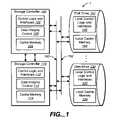
- FIG. 1is a block diagram of an exemplary storage system embodying features and aspects hereof to utilize write-back cache management techniques within the local cache memory of disk drives of the system while maintaining data integrity in the system.
- FIG. 2is a diagram of an exemplary state machine model operable in a storage controller for implementing features and aspects hereof to manage cached blocks within cache memory of a storage system controller so as to utilize write-back cache management techniques within the local cache memory of disk drives of the system while maintaining data integrity in the system.
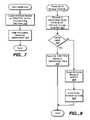
- FIGS. 3-8are flowcharts describing exemplary methods operable in a storage controller for implementing features and aspects hereof to manage cached blocks within cache memory of a storage system controller so as to utilize write-back cache management techniques within the local cache memory of disk drives of the system while maintaining data integrity in the system.
- FIG. 1is a block diagram of a storage system 1 embodying features and aspects hereof to maintain data integrity between storage controller cache memory contents and corresponding local cache memory contents of disk drives of the system 1 while permitting performance optimizations utilizing the write-back cache techniques for managing local cache memory within individual disk drives.
- Storage controller 100may be a storage controller embedded within a storage subsystem or may be, for example, a host bus adapter (“HBA”) integrated within a corresponding computing system (not shown).
- HBAhost bus adapter
- Control logic and interface element 102 within storage controller 100may include general and/or special purpose processing elements for interfacing with attached host systems (not shown), for interfacing with disk drives 120 and 130 , and for managing overall operations of the storage controller to store and retrieve information on disk drives 120 and 130 .
- Storage controllers 100 and 110exchange information with disk drives 120 and 130 via one or more communication media 150 and 152 .
- Communication media 150 and/or 152may be a SCSI parallel bus structure, other parallel bus structures, or any of several high speed serial media and corresponding protocols including, for example, Fibre Channel.
- control logic and interface element 102may include programmable processing elements such as a general purpose processor (“CPU”) and/or additional special purpose processing elements for managing the various lower level control operations (e.g., RAID storage management redundancy generation and checking features, striping features, etc.). Where such programmable processing elements are utilized, control logic and interface element 102 may include appropriate memory elements for storing program instructions and associated data.
- control logic and interface element 102may comprise a plurality of commercially available circuits integrated to cooperate through appropriate programmed instructions or may comprise custom integrated circuit designs integrating one or more of the various control and interface features into any number of integrated circuits. Such design choices are well known to the list of ordinary skill in the art.
- storage controller 100typically includes cache memory 104 used for storing blocks of data in a high speed cache for further, subsequent management by storage controller 100 .
- Cache memory 104may be any suitable form of memory components including, for example, high speed static memory devices as well as more typical dynamic RAM or SDRAM memory components.
- host requestsare received in storage controller 100 from attached host systems (not shown) and processed more quickly through use of cache memory 104 .
- control logic and interface element 102receives write data from a host write request and stores the data in cache memory 104 .
- a completion responseis forwarded to the attached host system upon successfully storing the write data in cache memory 104 .
- control logic and interface element 102will transfer the write data stored in its cache memory 104 to the persistent storage capacity of one or more disk drives 120 and 130 .
- a redundant or alternate storage controller 110may be provided in storage system 1 to permit rapid takeover of control of the system 1 in the event of failure of the primary storage controller 100 .
- Alternate storage controller 110therefore includes identical components including control logic and interface 112 and corresponding cache memory 114 . Where such an alternate controller 110 is present in system 1 , the alternate controller 110 and the primary storage controller 100 may communicate via the communication media 150 and 152 of via a dedicated, single or redundant communication medium 154 .
- disk drives 120 and 130typically include a local control logic element 122 and 132 , respectively, and associated local cache memory 124 and 134 , respectively.
- Data transferred from cache memory 104 of storage controller 100may be stored in the local cache memory 124 or 134 by operation of the local control logic and interface element 122 or 132 of respective disk drives 120 and 130 .
- write-back cache management techniquesare generally not utilized within disk drives 120 and 130 . Not using the write-back cache mode in disk drives within a storage subsystem helps assure integrity of the data stored in system 1 .
- the storage controller 100In write-back cache management mode of operation, the storage controller 100 would normally transfer data from its cache memory 104 to the disk drives' local cache memory 124 and/or 134 . Upon completion of the transfer between cache memories, the storage controller, relying on write-back cache techniques in the disk drives as presently known in the art, would continue with other processing presuming that the data was successfully recorded in one or more of the affected disk drives 120 and 130 . Should power be lost in the disk drives 120 and 130 or other reset operations associated with the disk drives, data stored in the volatile local cache memory of such a reset disk drive 120 or 130 may be lost.
- storage controller 100 and alternate storage controller 110may include data integrity control element 103 and 113 , respectively, to help assure data integrity while utilizing write-back cache management techniques within the disk drives 120 and 130 .
- features and aspects hereofpermit improved performance of the storage system 1 by permitting the disk drive local control logic 122 and 132 to perform local optimizations in storing information on the disk drive storage media.
- the local control logic 122 or 132may more effectively apply so-called “elevator” optimizations or other scheduling related optimizations to record blocks of data to the persistent storage media of the disk drive 120 or 130 .
- These optimizationsmay be better applied within the disk drive control elements 122 and 132 because more blocks of data are available within the local cache memory 124 or 134 to permit better selection of blocks to be written by the control logic 122 or 132 .
- integrity control element 103 and 113 of storage controllers 100 and 110utilize write-back cache management techniques in the disk drives 120 and 130 for transfers to disk drives 120 and 130 .
- features and aspects hereof exemplified by elements 103 and/or 113help assure integrity of the managed data. More specifically, data transferred from the storage controllers' cache memory 104 or 114 to the local cache memory 124 or 134 of disk drives 120 and 130 , respectively, is maintained within the cache memory 104 or 114 , respectively, until verification that the data is persistently stored in the disk drives 120 and/or 130 .
- the dataremains in the storage controllers' cache memory 104 and/or 114 until the data in the local cache memory 124 and/or 134 is flushed to the persistent storage medium of the disk drives 120 and/or 130 , respectively.
- Exemplary methods and process easier associated with operation of the integrity control element 103 and 113are discussed in further details here in bellow.
- FIG. 1is intended merely as exemplary of a typical storage system where features and aspects hereof are beneficially applied. Numerous other equivalent architectures and configurations will be readily apparent to those of ordinary skill in the art.
- any number of storage controllers(one or more) may be utilized in such a configuration
- any number of communication media 154may be applied for exchange of information between such redundant controllers
- any number of communication buses 150 and 152may be configured in such a storage system
- any number of disk drives one of 120 and 130may be applied in such a storage system.
- Numerous equivalent configurationsmay beneficially apply the integrity control features and aspects hereof as exemplified by elements 103 and 113 of FIG. 1 .
- FIG. 2is an exemplary state machine model diagram describing the management of individual cache blocks or groups of cache blocks within the cache memory of a storage controller operating in accordance with features and aspects hereof.
- All cache blocksmay be initially in an EMPTY state 200 at initialization of a storage system.
- EMPTYAs write-requests are processed by a storage controller in accordance with features and aspects hereof, one or more unused blocks presently marked as EMPTY may be allocated for storage of the host supplied write data.
- the host-supplied write datais recorded in the allocated blocks as indicated by transition arrow 220 , the affected blocks are marked as now in a DIRTY state 202 .
- a storage controllerwill determine that one or more blocks of cache memory marked as DIRTY should be flushed or posted to corresponding locations on one or more disk drives of the storage system.
- one or more cache memory blocks marked as DIRTYmay be selected for posting or flushing to the disk drives using a write-through mode for the local cache memory associated with the affected disk drives.
- the selected DIRTY blocksare successfully written to the affected disk drives in a write-through cache management mode for the disk drive's local cache memory, as indicated by transition arrow 236 , the transferred DIRTY blocks are marked as now in the CLEAN state 210 . Blocks so marked as CLEAN may retain the data recorded therein for use, for example, in satisfying subsequent read requests.
- the storage controllermay determine that additional EMPTY blocks are required to process additional host write requests and may therefore free blocks marked as CLEAN for re-use as EMPTY blocks as indicated by a transition arrow 234 .
- the state machine model described thusfarrepresents typical present storage systems where only the write-through cache management mode is used for writing data to affected disk drives from the storage controller.
- such a typical state machine modelmay be enhanced to a permit utilization of write-back cache management features within the disk drives.
- the storage controllerdetermines that dirty blocks may be flushed or posted to associated disk drives, one or more selected dirty blocks may be written to the affected disk drives utilizing write-back cache management techniques for management of the local cache memory within the affected disk drives.
- the selected dirty blocksare written to the local cache memory of the affected disk drives as indicated by a transition arrow 238 and the blocks so transferred are marked within the cache memory of the storage controller as now in a WRITTEN state 206 .
- the disk drive controller of each disk drivemay independently manage the local cache memory of that disk drive. Independent of the operation of the storage controller, the local disk controller may retain data within the local cache memory of the disk drives or may choose to flush or post the data to the persistent media of the disk drives (i.e., the disk drive platter surfaces).
- the storage controllersince the local cache memory of the affected disk drives is typically a volatile form of memory, the storage controller, in accordance with features and aspects hereof, retains the cache memory blocks marked as WRITTEN within the cache memory of the storage controller until such time as the blocks can be verified as correctly posted or flushed to the persistent media of the affected disk drives.
- the storage controllermay determine that the WRITTEN state blocks in the storage controller's cache memory have been successfully flushed or posted from the disk drives' local cache memories to the persistent storage media of the affected disk drives.
- the WRITTEN blocks detected as having been successfully flushed to the disk drives persistent storage mediumare marked as now in the CLEAN state 210 .
- CLEAN blocksmay eventually be freed for re-use as indicated by transition arrow 234 and marked as in the EMPTY state 200 .
- the storage controllermay later determine that WRITTEN blocks in its cache memory have been successfully posted or flushed from the affected disk drives' local cache memory to the persistent storage media of the affected disk drives by synchronization operations. Synchronization operations are defined, for example, in the SCSI specifications and other disk drive interface and operation specifications as well known to those of ordinary skill in the art. Synchronize operations may be directed to selected disk drives by operation of the storage controller to force the flushing of blocks from the local cache memory of the addressed disk drive onto the persistent storage medium of that disk drive. Such operations may be performed periodically or as background processing tasks within the storage controller as the storage controller determines that additional CLEAN blocks are needed for continued operation of the storage controller.
- the state machine of FIG. 2may be further enhanced to assure integrity of the data by forcing mirroring of DIRTY data blocks to an alternate storage controller.
- Blocks that are marked in the DIRTY state 202may be first copied to the alternate controller as indicated by a transition arrow 222 .
- the DIRTY blocks so mirrored to the alternate controllermay then be marked in the MIRRORED state 204 .
- blocks initially marked as DIRTYmay be immediately mirrored to the alternate controller and hence rapidly transitioned from the DIRTY state 202 to the MIRRORED state 204 .
- DIRTY blocksmay be transferred substantially simultaneously to both a primary and an alternate storage controller.
- the transition between the DIRTY state 202 and the MIRRORED state(as indicated by arrow 222 ) may be essentially instantaneous or, the states may be in essence merged into a single state.
- blocksmay be recorded as DIRTY blocks for any desired period of time where the storage controller later determines which DIRTY blocks should be mirrored to the alternate controller. Such design choices are readily apparent to those of ordinary skill in the art.
- MIRRORED blocksmay then be selected for writing to affected disk drives at some subsequent point in time. MIRRORED blocks selected for writing to the disk drives may then be transferred to the disk drives and transitioned to the WRITTEN state 206 as indicated by arrow 224 . If the disk drive local cache memory is disabled for any of several reasons the MIRRORED blocks so transferred to the disk drives may be marked as in the UNMIRRORED state 208 as indicated by transition arrow 228 .
- Such operationis essentially analogous to utilizing local cache memory of the affected disk drives in a simple write-through cache management mode. If the local cache memory is enabled for use and is operated in a write-back cache management mode, MIRRORED blocks transferred to the disk drives as indicated by arrow 224 are then marked as in the WRITTEN state 206 . As discussed above, WRITTEN blocks may be selected by the storage controller at a subsequent time to be synchronized or flushed from the local cache memory to the persistent storage medium of the affected disk drives. When the storage controller detects that WRITTEN blocks have been flushed to the persistent storage of the affected disk drives, the blocks so synchronized may be marked in the UNMIRRORED state 208 as indicated by transition arrow 230 .
- Blocks in the UNMIRRORED state 208may then quickly transition as indicated by a transition arrow 232 into the CLEAN state 210 and then, as discussed above, into the EMPTY state 200 as indicated by arrow 234 when additional EMPTY blocks are needed to process a host request.
- FIG. 2is intended merely as exemplary of one possible state machine model for managing cache memory blocks within the cache memory of a storage controller and optionally in conjunction with an alternate storage controller. Numerous equivalent state machine models adapted to enable utilization of write-back cache mode cache management mode within the disk drives of the storage system will be readily apparent to those of ordinary skill in the art.
- FIGS. 3 through 8are flowcharts describing exemplary methods associated with features and aspects hereof.
- the methods of FIGS. 3 through 8represent one exemplary implementation of the state machine model of operation described above with respect to FIG. 2 .
- FIG. 3is a flowchart describing an exemplary method for processing a write request received from a host system or otherwise generated for recording received write data in the cache memory of the storage controller. Such processing is represented in FIG. 2 as the transition arrow 220 between EMPTY state 200 and DIRTY state 202 .
- Responsive to receipt of a write request from, for example, and attached host system element 300is first operable to allocate EMPTY blocks of from the storage controller's cache memory to be used to store the write data associated with the received write request.
- the blocks so allocatedare annotated as being associated with a particular volume (e.g., a disk drive) and with a logical block address within the volume.
- the EMPTY blocks so allocatedare then marked as DIRTY by operation of element 302 and the host system supplied write data is copied to the allocated blocks.
- the DIRTY blocksmay be copied to the alternate controller and marked as MIRRORED blocks as indicated in transition arrow 222 of FIG. 2 .
- element 304 of FIG. 3is operable to copy the just allocated and filled DIRTY blocks to the alternate controller's cache memory.
- Element 306marks of the transferred blocks as MIRRORED blocks.
- the exemplary method depicted in the flowchart of FIG. 4is operable to recycle CLEAN blocks for re-use as EMPTY blocks.
- the process of FIG. 4may be operable as a periodic background task or may be operable in response to failure of element 300 of FIG. 3 to locate sufficient EMPTY blocks for allocations to satisfy an incoming write request.
- the processing of FIG. 4is roughly the equivalent of the transition arrow 234 between the CLEAN state 210 and the EMPTY state 200 of FIG. 2 .
- Element 400 of FIG. 4is first operable to locate blocks presently marked as CLEAN.
- the number of CLEAN blocks to be locatedmay be determined in accordance with any of several well known parameters or techniques. In particular, where element 300 of FIG. 3 requires a particular number of blocks to be allocated in response to receipt of a host write request, element 400 of FIG. 4 may be operable to locate that required number of blocks.
- Element 402 of FIG. 4is then operable to mark the CLEAN blocks so located by element 400 as EMPTY blocks available for re-use and processing of new host write requests.
- FIG. 5is a flowchart describing operation of an exemplary method in accordance with features and aspects hereof to select MIRRORED blocks to be flushed or posted to the local cache memory of affected disk drives operating in a write-back cache management mode.
- the operation of FIG. 5is roughly equivalent to the transition from MIRRORED state 204 to WRITTEN state 206 by arrow 224 of FIG. 2 or, as discussed, from DIRTY state 202 to WRITTEN state 206 as indicated by arrow 238 of FIG. 2 .
- Element 500is first operable to locate blocks presently marked as MIRRORED (where redundant controllers are used to mirror cache contents) or marked as DIRTY (where DIRTY blocks are not mirrored to an alternate controller). The number and selection of blocks to be so posted may be determined in accordance with any parameters or known techniques. Element 502 is then operable to transfer the selected MIRRORED (or DIRTY) blocks to the affected disk drives identified by the annotations associated with the selected blocks in the storage controller's cache memory. As noted, by so utilizing the write-back cache management mode of the local cache memory in the affected disk drives, the affected disk drives may more readily and fully optimize their respective operations in recording information from their respective local cache memories to their respective persistent storage media.
- Element 504marks the selected blocks as WRITTEN until such later time as the blocks are verified as being properly flushed from the local cache memory of the disk drives onto the persistent storage media of the disk drives.
- FIG. 6is a flowchart describing an exemplary method in accordance with features and aspects hereof to detect proper synchronization or flushing of blocks recorded in the local cache memory of selected disk drives for storage on the persistent storage medium of affected disk drives.
- the method of the flowchart a FIG. 6approximately corresponds to the state transition 230 from the WRITTEN state 206 to the UNMIRRORED state 208 or the transition 240 from the WRITTEN state 206 to the CLEAN state 210 all of FIG. 2 .
- Element 600 of FIG. 6is first operable to select disk drives presently storing cache memory blocks marked as WRITTEN in the cache memory of the storage controller. The particular number and selection of blocks may be in accordance with any parameters or known techniques readily apparent to those of ordinary skilled the art.
- Element 602is then operable to issue appropriate commands to the disk drives affected by the selected blocks to cause the affected disk drives to synchronize its respective local cache memory with the respective persistent storage media associated with that disk drive.
- Such commandsare well known to those of ordinary skill and the art and are well documented in, for example, SCSI specifications as well as other disk drive command and status protocol specifications. Such specifications are readily available to those of ordinary skill in the art including, for example, on the Internet at www.t10.org.
- Element 604is operable to determine whether the issued commands succeeded or failed in causing the local cache memory of the disk drives to be synchronized with the persistent storage medium of the corresponding disk drives. If the command was seemingly unsuccessful, the method completes to be retried at a subsequent point in time. If the synchronization commands apparently succeeded, element 606 is then operable to mark the selected blocks so synchronized as now in the UNMIRRORED state. Next, either immediately or at some later point in time as a matter of design choice, the selected blocks are marked as now in the CLEAN state representing the verified knowledge that the information has been successfully recorded on the persistent storage media of affected disk drives.
- step 606may be skipped such that the WRITTEN blocks successfully flushed from the local cache memory of the affected disk drives may be simply marked as CLEAN.
- FIG. 7is a flowchart describing an exemplary method in accordance with features and aspects hereof to detect that blocks presently marked as in the WRITTEN state have been possibly lost from the local cache memory of one or more affected disk drives. Such processing corresponds approximately to transition arrow 226 from the WRITTEN state 206 back to the MIRRORED state 204 (or arrow 242 from the WRITTEN state 206 back to the DIRTY state 202 ).
- element 700Upon sensing the reset or failure of one or more disk drives, element 700 is operable within the storage controller to locate all blocks marked as WRITTEN and corresponding to the one or more disk drives sensed as having been reset or otherwise failed so as to possibly have lost data in its local cache memory. Element 702 is then operable to mark the located locks as having been restored to the MIRRORED state. The blocks so marked again as mirrored will eventually be written to the disk drives again as described above with respect to FIG. 5 .
- FIG. 8is a flowchart describing an exemplary method in accordance with features and aspects hereof to initialize a storage controller.
- a storage controllerWhen a storage controller is initialized it may determine whether an alternate controller is configured and available. If so, the alternate controller may be continuing operations following failure or other reset of the controller now initializing. In such a case, the initializing controller may re-initialize the content of its cache memory from the present content of the alternate controller cache. If there is no alternate controller configured or available, or for any other reason no presently valid cache memory content is available, then the initializing controller may simply initialize its cache content to indicate that all cache blocks are presently in the EMPTY state.
- Element 800is first operable to attempt to recover or synchronize the cache memory of this initializing controller with an alternate storage controller if any is found to have valid cache content. Element 802 then determines whether any such valid cache content was located and, if so, whether it is valid for use. If not, elements 806 and 808 are operable to mark all cache blocks in this storage controller's cache memory as valid and in the EMPTY state. If element 802 finds that valid cache content was located from another alternate controller, then element 804 is operable to transition all blocks in the restored cache presently marked in the WRITTEN state into the MIRRORED state.
Landscapes
- Engineering & Computer Science (AREA)
- Theoretical Computer Science (AREA)
- Physics & Mathematics (AREA)
- General Engineering & Computer Science (AREA)
- General Physics & Mathematics (AREA)
- Memory System Of A Hierarchy Structure (AREA)
Abstract
Description
Claims (5)
Priority Applications (2)
| Application Number | Priority Date | Filing Date | Title |
|---|---|---|---|
| US11/025,562US7441081B2 (en) | 2004-12-29 | 2004-12-29 | Write-back caching for disk drives |
| US12/191,445US8065479B2 (en) | 2004-12-29 | 2008-08-14 | Methods and structure for improved storage system performance with write-back caching for disk drives |
Applications Claiming Priority (1)
| Application Number | Priority Date | Filing Date | Title |
|---|---|---|---|
| US11/025,562US7441081B2 (en) | 2004-12-29 | 2004-12-29 | Write-back caching for disk drives |
Related Child Applications (1)
| Application Number | Title | Priority Date | Filing Date |
|---|---|---|---|
| US12/191,445ContinuationUS8065479B2 (en) | 2004-12-29 | 2008-08-14 | Methods and structure for improved storage system performance with write-back caching for disk drives |
Publications (2)
| Publication Number | Publication Date |
|---|---|
| US20060143407A1 US20060143407A1 (en) | 2006-06-29 |
| US7441081B2true US7441081B2 (en) | 2008-10-21 |
Family
ID=36613141
Family Applications (2)
| Application Number | Title | Priority Date | Filing Date |
|---|---|---|---|
| US11/025,562Expired - Fee RelatedUS7441081B2 (en) | 2004-12-29 | 2004-12-29 | Write-back caching for disk drives |
| US12/191,445Expired - Fee RelatedUS8065479B2 (en) | 2004-12-29 | 2008-08-14 | Methods and structure for improved storage system performance with write-back caching for disk drives |
Family Applications After (1)
| Application Number | Title | Priority Date | Filing Date |
|---|---|---|---|
| US12/191,445Expired - Fee RelatedUS8065479B2 (en) | 2004-12-29 | 2008-08-14 | Methods and structure for improved storage system performance with write-back caching for disk drives |
Country Status (1)
| Country | Link |
|---|---|
| US (2) | US7441081B2 (en) |
Cited By (22)
| Publication number | Priority date | Publication date | Assignee | Title |
|---|---|---|---|---|
| US20070070829A1 (en)* | 2005-09-27 | 2007-03-29 | Fujitsu Limited | Disk storage device and cache control method for disk storage device |
| US20070233961A1 (en)* | 2006-03-31 | 2007-10-04 | Banning John P | Multi-portioned instruction memory |
| US20080082856A1 (en)* | 2006-09-28 | 2008-04-03 | Emc Corporation | Recovering from a storage processor failure using write cache preservation |
| US20090100284A1 (en)* | 2007-10-12 | 2009-04-16 | Dell Products L.P. | System and Method for Synchronizing Redundant Data In A Storage Array |
| US7747896B1 (en)* | 2006-06-30 | 2010-06-29 | Guillermo Rozas | Dual ported replicated data cache |
| WO2012016209A3 (en)* | 2010-07-30 | 2012-08-02 | Fusion-Io, Inc. | Apparatus, system, and method for redundant write caching |
| US8443134B2 (en) | 2006-12-06 | 2013-05-14 | Fusion-Io, Inc. | Apparatus, system, and method for graceful cache device degradation |
| US8489817B2 (en) | 2007-12-06 | 2013-07-16 | Fusion-Io, Inc. | Apparatus, system, and method for caching data |
| US8825937B2 (en) | 2011-02-25 | 2014-09-02 | Fusion-Io, Inc. | Writing cached data forward on read |
| US8966184B2 (en) | 2011-01-31 | 2015-02-24 | Intelligent Intellectual Property Holdings 2, LLC. | Apparatus, system, and method for managing eviction of data |
| US9053027B1 (en)* | 2011-12-21 | 2015-06-09 | Emc Corporation | Techniques for maintaining and restoring dirty caches across CPU resets |
| US9104599B2 (en) | 2007-12-06 | 2015-08-11 | Intelligent Intellectual Property Holdings 2 Llc | Apparatus, system, and method for destaging cached data |
| US9141543B1 (en) | 2012-01-06 | 2015-09-22 | Marvell International Ltd. | Systems and methods for writing data from a caching agent to main memory according to a pre-clean criterion |
| US9183246B2 (en) | 2013-01-15 | 2015-11-10 | Microsoft Technology Licensing, Llc | File system with per-file selectable integrity |
| US9251086B2 (en) | 2012-01-24 | 2016-02-02 | SanDisk Technologies, Inc. | Apparatus, system, and method for managing a cache |
| US9367356B2 (en) | 2010-06-17 | 2016-06-14 | Microsoft Technology Licensing, Llc | Resource access control |
| US9519540B2 (en) | 2007-12-06 | 2016-12-13 | Sandisk Technologies Llc | Apparatus, system, and method for destaging cached data |
| US9600184B2 (en) | 2007-12-06 | 2017-03-21 | Sandisk Technologies Llc | Apparatus, system, and method for coordinating storage requests in a multi-processor/multi-thread environment |
| US9734086B2 (en) | 2006-12-06 | 2017-08-15 | Sandisk Technologies Llc | Apparatus, system, and method for a device shared between multiple independent hosts |
| US9767032B2 (en) | 2012-01-12 | 2017-09-19 | Sandisk Technologies Llc | Systems and methods for cache endurance |
| US10142416B2 (en)* | 2016-05-27 | 2018-11-27 | Netapp, Inc. | Methods for facilitating planned data container transitions and devices thereof |
| US10657069B2 (en) | 2017-05-15 | 2020-05-19 | Seagate Technology Llc | Fine-grained cache operations on data volumes |
Families Citing this family (56)
| Publication number | Priority date | Publication date | Assignee | Title |
|---|---|---|---|---|
| US8019937B2 (en)* | 2004-07-21 | 2011-09-13 | Infortrend Technology, Inc. | Applying storage device commit-cached-data-to-media functionality to improve data security in systems that allow storage devices to cache writes |
| US7360112B2 (en)* | 2005-02-07 | 2008-04-15 | International Business Machines Corporation | Detection and recovery of dropped writes in storage devices |
| US7337350B2 (en)* | 2005-02-09 | 2008-02-26 | Hitachi, Ltd. | Clustered storage system with external storage systems |
| JP2006268524A (en)* | 2005-03-24 | 2006-10-05 | Fujitsu Ltd | Storage device, control method thereof, and program |
| US20070076685A1 (en)* | 2005-09-30 | 2007-04-05 | Pak-Lung Seto | Programmable routing for frame-packet based frame processing |
| US7627713B2 (en)* | 2005-12-29 | 2009-12-01 | Intel Corporation | Method and apparatus to maintain data integrity in disk cache memory during and after periods of cache inaccessibility |
| JP2007193448A (en)* | 2006-01-17 | 2007-08-02 | Toshiba Corp | Information recording apparatus and control method thereof |
| US7558913B2 (en) | 2006-06-20 | 2009-07-07 | Microsoft Corporation | Atomic commit of cache transfer with staging area |
| US8234457B2 (en)* | 2006-06-30 | 2012-07-31 | Seagate Technology Llc | Dynamic adaptive flushing of cached data |
| US7761659B2 (en)* | 2006-06-30 | 2010-07-20 | Seagate Technology Llc | Wave flushing of cached writeback data to a storage array |
| US20080098185A1 (en)* | 2006-10-20 | 2008-04-24 | Saleem Mohideen | Remote file system with efficient handling of uncommitted pages |
| US8489820B1 (en)* | 2008-03-18 | 2013-07-16 | Netapp, Inc | Speculative copying of data from main buffer cache to solid-state secondary cache of a storage server |
| US8051259B2 (en)* | 2008-06-23 | 2011-11-01 | International Business Machines Corporation | Space efficient de-allocation for cascade/multiple target flash copy cleaning |
| WO2010020992A1 (en)* | 2008-08-21 | 2010-02-25 | Xsignnet Ltd. | Storage system and method of operating thereof |
| US8078906B2 (en)* | 2008-08-21 | 2011-12-13 | Infinidat, Ltd. | Grid storage system and method of operating thereof |
| US8495291B2 (en)* | 2008-08-21 | 2013-07-23 | Infinidat Ltd. | Grid storage system and method of operating thereof |
| US8443137B2 (en)* | 2008-08-21 | 2013-05-14 | Infinidat Ltd. | Grid storage system and method of operating thereof |
| US20100049919A1 (en)* | 2008-08-21 | 2010-02-25 | Xsignnet Ltd. | Serial attached scsi (sas) grid storage system and method of operating thereof |
| US8452922B2 (en)* | 2008-08-21 | 2013-05-28 | Infinidat Ltd. | Grid storage system and method of operating thereof |
| US8499120B2 (en)* | 2008-10-17 | 2013-07-30 | Seagate Technology Llc | User selectable caching management |
| US8533445B2 (en)* | 2009-04-21 | 2013-09-10 | Hewlett-Packard Development Company, L.P. | Disabling a feature that prevents access to persistent secondary storage |
| US9563397B1 (en)* | 2010-05-05 | 2017-02-07 | Western Digital Technologies, Inc. | Disk drive using non-volatile cache when garbage collecting log structured writes |
| US8751789B2 (en)* | 2010-09-17 | 2014-06-10 | International Business Machines Corporation | General purpose distributed encrypted file system |
| US20120297147A1 (en)* | 2011-05-20 | 2012-11-22 | Nokia Corporation | Caching Operations for a Non-Volatile Memory Array |
| WO2013048497A1 (en) | 2011-09-30 | 2013-04-04 | Intel Corporation | Apparatus and method for implementing a multi-level memory hierarchy |
| EP3364304B1 (en) | 2011-09-30 | 2022-06-15 | INTEL Corporation | Memory channel that supports near memory and far memory access |
| US9600407B2 (en) | 2011-09-30 | 2017-03-21 | Intel Corporation | Generation of far memory access signals based on usage statistic tracking |
| KR20130040486A (en)* | 2011-10-14 | 2013-04-24 | 삼성전자주식회사 | Storage device and user device using the same |
| US9256526B2 (en)* | 2012-02-23 | 2016-02-09 | National Taiwan University | Flash memory storage system and access method |
| US9798623B2 (en)* | 2012-05-11 | 2017-10-24 | Seagate Technology Llc | Using cache to manage errors in primary storage |
| US9235535B1 (en)* | 2012-10-31 | 2016-01-12 | Emc Corporation | Method and apparatus for reducing overheads of primary storage by transferring modified data in an out-of-order manner |
| US9471245B1 (en) | 2012-10-31 | 2016-10-18 | Emc Corporation | Method and apparatus for transferring modified data efficiently |
| US10176183B1 (en) | 2012-10-31 | 2019-01-08 | EMC IP Holding Company LLC | Method and apparatus for reducing overheads of primary storage while transferring modified data |
| US9152501B2 (en) | 2012-12-19 | 2015-10-06 | International Business Machines Corporation | Write performance in fault-tolerant clustered storage systems |
| US9106260B2 (en)* | 2012-12-19 | 2015-08-11 | Advanced Micro Devices, Inc. | Parity data management for a memory architecture |
| CN103049397B (en)* | 2012-12-20 | 2015-09-16 | 中国科学院上海微系统与信息技术研究所 | A kind of solid state hard disc inner buffer management method based on phase transition storage and system |
| US9280469B1 (en)* | 2012-12-28 | 2016-03-08 | Emc Corporation | Accelerating synchronization of certain types of cached data |
| US9037799B2 (en)* | 2013-02-11 | 2015-05-19 | Avago Technologies General Ip (Singapore) Pte Ltd | Rebuild of redundant secondary storage cache |
| US9842053B2 (en)* | 2013-03-15 | 2017-12-12 | Sandisk Technologies Llc | Systems and methods for persistent cache logging |
| US9152342B1 (en) | 2013-04-16 | 2015-10-06 | Emc Corporation | Read-write access in a read-only environment |
| JP5924819B2 (en)* | 2013-06-10 | 2016-05-25 | 日本電気株式会社 | Data integrity processing apparatus and data integrity processing program |
| US9239797B2 (en)* | 2013-08-15 | 2016-01-19 | Globalfoundries Inc. | Implementing enhanced data caching and takeover of non-owned storage devices in dual storage device controller configuration with data in write cache |
| US9594583B2 (en)* | 2013-11-12 | 2017-03-14 | Red Hat, Inc. | Lightweight snapshots for virtual disks |
| JP2016057876A (en)* | 2014-09-10 | 2016-04-21 | 富士通株式会社 | Information processing apparatus, input/output control program, and input/output control method |
| US10157129B2 (en) | 2014-12-17 | 2018-12-18 | International Business Machines Corporation | Mirroring a cache having a modified cache state |
| WO2017022002A1 (en)* | 2015-07-31 | 2017-02-09 | 株式会社日立製作所 | Storage device, storage system, and control method for storage system |
| KR20170074264A (en)* | 2015-12-21 | 2017-06-30 | 에스케이하이닉스 주식회사 | Memory system and operation method for the same |
| CN107515727B (en)* | 2016-06-16 | 2020-09-25 | 伊姆西Ip控股有限责任公司 | Method and system for managing memory in a storage system |
| JP2018022404A (en)* | 2016-08-05 | 2018-02-08 | 富士通株式会社 | Storage system, storage control device, and storage control program |
| CN106502595A (en)* | 2016-11-11 | 2017-03-15 | 济南浪潮高新科技投资发展有限公司 | A kind of isomery storage medium data consistency method |
| US10474582B2 (en)* | 2017-04-28 | 2019-11-12 | Seagate Technology Llc | NAND flash storage device and methods using non-NAND storage cache |
| US10776267B2 (en)* | 2017-12-11 | 2020-09-15 | Red Hat, Inc. | Mirrored byte addressable storage |
| US10949346B2 (en) | 2018-11-08 | 2021-03-16 | International Business Machines Corporation | Data flush of a persistent memory cache or buffer |
| US11327858B2 (en)* | 2020-08-11 | 2022-05-10 | Seagate Technology Llc | Preserving data integrity during controller failure |
| KR102343600B1 (en)* | 2020-12-23 | 2021-12-27 | 주식회사 파두 | Memory controller and storage device including the same |
| CN118069410A (en)* | 2022-11-24 | 2024-05-24 | 长江存储科技有限责任公司 | Operation method, memory controller, system and electronic device |
Citations (9)
| Publication number | Priority date | Publication date | Assignee | Title |
|---|---|---|---|---|
| US5197144A (en)* | 1990-02-26 | 1993-03-23 | Motorola, Inc. | Data processor for reloading deferred pushes in a copy-back data cache |
| US5274799A (en)* | 1991-01-04 | 1993-12-28 | Array Technology Corporation | Storage device array architecture with copyback cache |
| US5295259A (en)* | 1991-02-05 | 1994-03-15 | Advanced Micro Devices, Inc. | Data cache and method for handling memory errors during copy-back |
| US5353423A (en)* | 1991-06-21 | 1994-10-04 | Compaq Computer Corporation | Memory controller for use with write-back cache system and multiple bus masters coupled to multiple buses |
| US5561779A (en)* | 1994-05-04 | 1996-10-01 | Compaq Computer Corporation | Processor board having a second level writeback cache system and a third level writethrough cache system which stores exclusive state information for use in a multiprocessor computer system |
| US5761705A (en)* | 1996-04-04 | 1998-06-02 | Symbios, Inc. | Methods and structure for maintaining cache consistency in a RAID controller having redundant caches |
| US5895485A (en)* | 1997-02-24 | 1999-04-20 | Eccs, Inc. | Method and device using a redundant cache for preventing the loss of dirty data |
| US5897655A (en)* | 1996-12-10 | 1999-04-27 | International Business Machines Corporation | System and method for cache replacement within a cache set based on valid, modified or least recently used status in order of preference |
| US5937433A (en)* | 1996-04-24 | 1999-08-10 | Samsung Electronics Co., Ltd. | Method of controlling hard disk cache to reduce power consumption of hard disk drive used in battery powered computer |
Family Cites Families (2)
| Publication number | Priority date | Publication date | Assignee | Title |
|---|---|---|---|---|
| US5371855A (en)* | 1979-06-04 | 1994-12-06 | Unisys Corporation | Disc cache subsystem having plural-level cache memories |
| US6865642B2 (en)* | 1998-06-24 | 2005-03-08 | International Business Machines Corporation | Method and apparatus for disk caching for an intermediary controller |
- 2004
- 2004-12-29USUS11/025,562patent/US7441081B2/ennot_activeExpired - Fee Related
- 2008
- 2008-08-14USUS12/191,445patent/US8065479B2/ennot_activeExpired - Fee Related
Patent Citations (10)
| Publication number | Priority date | Publication date | Assignee | Title |
|---|---|---|---|---|
| US5197144A (en)* | 1990-02-26 | 1993-03-23 | Motorola, Inc. | Data processor for reloading deferred pushes in a copy-back data cache |
| US5274799A (en)* | 1991-01-04 | 1993-12-28 | Array Technology Corporation | Storage device array architecture with copyback cache |
| US5526482A (en)* | 1991-01-04 | 1996-06-11 | Emc Corporation | Storage device array architecture with copyback cache |
| US5295259A (en)* | 1991-02-05 | 1994-03-15 | Advanced Micro Devices, Inc. | Data cache and method for handling memory errors during copy-back |
| US5353423A (en)* | 1991-06-21 | 1994-10-04 | Compaq Computer Corporation | Memory controller for use with write-back cache system and multiple bus masters coupled to multiple buses |
| US5561779A (en)* | 1994-05-04 | 1996-10-01 | Compaq Computer Corporation | Processor board having a second level writeback cache system and a third level writethrough cache system which stores exclusive state information for use in a multiprocessor computer system |
| US5761705A (en)* | 1996-04-04 | 1998-06-02 | Symbios, Inc. | Methods and structure for maintaining cache consistency in a RAID controller having redundant caches |
| US5937433A (en)* | 1996-04-24 | 1999-08-10 | Samsung Electronics Co., Ltd. | Method of controlling hard disk cache to reduce power consumption of hard disk drive used in battery powered computer |
| US5897655A (en)* | 1996-12-10 | 1999-04-27 | International Business Machines Corporation | System and method for cache replacement within a cache set based on valid, modified or least recently used status in order of preference |
| US5895485A (en)* | 1997-02-24 | 1999-04-20 | Eccs, Inc. | Method and device using a redundant cache for preventing the loss of dirty data |
Cited By (38)
| Publication number | Priority date | Publication date | Assignee | Title |
|---|---|---|---|---|
| US7603517B2 (en)* | 2005-09-27 | 2009-10-13 | Fujitsu Limited | Disk storage device and cache control method for disk storage device |
| US20070070829A1 (en)* | 2005-09-27 | 2007-03-29 | Fujitsu Limited | Disk storage device and cache control method for disk storage device |
| US20070233961A1 (en)* | 2006-03-31 | 2007-10-04 | Banning John P | Multi-portioned instruction memory |
| US8656214B2 (en) | 2006-06-30 | 2014-02-18 | Guillermo Rozas | Dual ported replicated data cache |
| US7747896B1 (en)* | 2006-06-30 | 2010-06-29 | Guillermo Rozas | Dual ported replicated data cache |
| US20100235716A1 (en)* | 2006-06-30 | 2010-09-16 | Guillermo Rozas | Dual ported replicated data cache |
| US7849350B2 (en)* | 2006-09-28 | 2010-12-07 | Emc Corporation | Responding to a storage processor failure with continued write caching |
| US20080082856A1 (en)* | 2006-09-28 | 2008-04-03 | Emc Corporation | Recovering from a storage processor failure using write cache preservation |
| US20080155307A1 (en)* | 2006-09-28 | 2008-06-26 | Emc Corporation | Responding to a storage processor failure with continued write caching |
| US7809975B2 (en)* | 2006-09-28 | 2010-10-05 | Emc Corporation | Recovering from a storage processor failure using write cache preservation |
| US8443134B2 (en) | 2006-12-06 | 2013-05-14 | Fusion-Io, Inc. | Apparatus, system, and method for graceful cache device degradation |
| US11960412B2 (en) | 2006-12-06 | 2024-04-16 | Unification Technologies Llc | Systems and methods for identifying storage resources that are not in use |
| US11847066B2 (en) | 2006-12-06 | 2023-12-19 | Unification Technologies Llc | Apparatus, system, and method for managing commands of solid-state storage using bank interleave |
| US11640359B2 (en) | 2006-12-06 | 2023-05-02 | Unification Technologies Llc | Systems and methods for identifying storage resources that are not in use |
| US8756375B2 (en) | 2006-12-06 | 2014-06-17 | Fusion-Io, Inc. | Non-volatile cache |
| US11573909B2 (en) | 2006-12-06 | 2023-02-07 | Unification Technologies Llc | Apparatus, system, and method for managing commands of solid-state storage using bank interleave |
| US9734086B2 (en) | 2006-12-06 | 2017-08-15 | Sandisk Technologies Llc | Apparatus, system, and method for a device shared between multiple independent hosts |
| US7814361B2 (en)* | 2007-10-12 | 2010-10-12 | Dell Products L.P. | System and method for synchronizing redundant data in a storage array |
| US20090100284A1 (en)* | 2007-10-12 | 2009-04-16 | Dell Products L.P. | System and Method for Synchronizing Redundant Data In A Storage Array |
| US9519540B2 (en) | 2007-12-06 | 2016-12-13 | Sandisk Technologies Llc | Apparatus, system, and method for destaging cached data |
| US9600184B2 (en) | 2007-12-06 | 2017-03-21 | Sandisk Technologies Llc | Apparatus, system, and method for coordinating storage requests in a multi-processor/multi-thread environment |
| US9104599B2 (en) | 2007-12-06 | 2015-08-11 | Intelligent Intellectual Property Holdings 2 Llc | Apparatus, system, and method for destaging cached data |
| US8706968B2 (en) | 2007-12-06 | 2014-04-22 | Fusion-Io, Inc. | Apparatus, system, and method for redundant write caching |
| US8489817B2 (en) | 2007-12-06 | 2013-07-16 | Fusion-Io, Inc. | Apparatus, system, and method for caching data |
| US9367356B2 (en) | 2010-06-17 | 2016-06-14 | Microsoft Technology Licensing, Llc | Resource access control |
| WO2012016209A3 (en)* | 2010-07-30 | 2012-08-02 | Fusion-Io, Inc. | Apparatus, system, and method for redundant write caching |
| US9092337B2 (en) | 2011-01-31 | 2015-07-28 | Intelligent Intellectual Property Holdings 2 Llc | Apparatus, system, and method for managing eviction of data |
| US8966184B2 (en) | 2011-01-31 | 2015-02-24 | Intelligent Intellectual Property Holdings 2, LLC. | Apparatus, system, and method for managing eviction of data |
| US8825937B2 (en) | 2011-02-25 | 2014-09-02 | Fusion-Io, Inc. | Writing cached data forward on read |
| US9141527B2 (en) | 2011-02-25 | 2015-09-22 | Intelligent Intellectual Property Holdings 2 Llc | Managing cache pools |
| US9053027B1 (en)* | 2011-12-21 | 2015-06-09 | Emc Corporation | Techniques for maintaining and restoring dirty caches across CPU resets |
| US9141543B1 (en) | 2012-01-06 | 2015-09-22 | Marvell International Ltd. | Systems and methods for writing data from a caching agent to main memory according to a pre-clean criterion |
| US9767032B2 (en) | 2012-01-12 | 2017-09-19 | Sandisk Technologies Llc | Systems and methods for cache endurance |
| US9251086B2 (en) | 2012-01-24 | 2016-02-02 | SanDisk Technologies, Inc. | Apparatus, system, and method for managing a cache |
| US9594798B2 (en) | 2013-01-15 | 2017-03-14 | Microsoft Technology Licensing, Llc | File system with per-file selectable integrity |
| US9183246B2 (en) | 2013-01-15 | 2015-11-10 | Microsoft Technology Licensing, Llc | File system with per-file selectable integrity |
| US10142416B2 (en)* | 2016-05-27 | 2018-11-27 | Netapp, Inc. | Methods for facilitating planned data container transitions and devices thereof |
| US10657069B2 (en) | 2017-05-15 | 2020-05-19 | Seagate Technology Llc | Fine-grained cache operations on data volumes |
Also Published As
| Publication number | Publication date |
|---|---|
| US20060143407A1 (en) | 2006-06-29 |
| US8065479B2 (en) | 2011-11-22 |
| US20080307160A1 (en) | 2008-12-11 |
Similar Documents
| Publication | Publication Date | Title |
|---|---|---|
| US7441081B2 (en) | Write-back caching for disk drives | |
| US10223272B2 (en) | Latency sensitive metadata object persistence operation for storage device | |
| US5809224A (en) | On-line disk array reconfiguration | |
| US6658542B2 (en) | Method and system for caching data in a storage system | |
| US8862808B2 (en) | Control apparatus and control method | |
| US8904129B2 (en) | Method and apparatus for backup and restore in a dynamic chunk allocation storage system | |
| US6606694B2 (en) | Write logging in mirrored disk subsystems | |
| US6523087B2 (en) | Utilizing parity caching and parity logging while closing the RAID5 write hole | |
| US8812901B2 (en) | Methods and apparatus for marking writes on a write-protected failed device to avoid reading stale data in a RAID storage system | |
| US7516268B2 (en) | Method for improving writing data efficiency and storage subsystem and system implementing the same | |
| US7908512B2 (en) | Method and system for cache-based dropped write protection in data storage systems | |
| EP1705574A2 (en) | Non-volatile backup for data cache | |
| JP4041473B2 (en) | Autonomous power loss recovery for multi-cluster storage subsystems | |
| US20010018728A1 (en) | Data storage system having redundant solid state data storage device | |
| CN113711189B (en) | System and method for managing reduced power failure energy requirements on solid state drives | |
| JP2002259062A (en) | Storage system and data copying method in storage system | |
| JP7318367B2 (en) | Storage control device and storage control program | |
| US7073029B2 (en) | Storage system using fast storage and log-structured storage | |
| WO2016006108A1 (en) | Storage and control method therefor | |
| WO2015186165A1 (en) | Storage system and method for controlling storage system | |
| CN112817520B (en) | Data disk refreshing method and device | |
| JP2006099802A (en) | Storage controller and cache memory control method | |
| JPH09212424A (en) | Disk cache and disk cache method | |
| JP2006277042A (en) | Array controller, disk array control method, and program | |
| JP2007334913A (en) | Storage device system and data copying method in storage device system |
Legal Events
| Date | Code | Title | Description |
|---|---|---|---|
| AS | Assignment | Owner name:LSI LOGIC CORP., CALIFORNIA Free format text:ASSIGNMENT OF ASSIGNORS INTEREST;ASSIGNOR:HUMLICEK, DONALD R.;REEL/FRAME:016139/0418 Effective date:20041216 | |
| AS | Assignment | Owner name:LSI CORPORATION, CALIFORNIA Free format text:MERGER;ASSIGNOR:LSI SUBSIDIARY CORP.;REEL/FRAME:020548/0977 Effective date:20070404 Owner name:LSI CORPORATION,CALIFORNIA Free format text:MERGER;ASSIGNOR:LSI SUBSIDIARY CORP.;REEL/FRAME:020548/0977 Effective date:20070404 | |
| FPAY | Fee payment | Year of fee payment:4 | |
| AS | Assignment | Owner name:DEUTSCHE BANK AG NEW YORK BRANCH, AS COLLATERAL AG Free format text:PATENT SECURITY AGREEMENT;ASSIGNORS:LSI CORPORATION;AGERE SYSTEMS LLC;REEL/FRAME:032856/0031 Effective date:20140506 | |
| AS | Assignment | Owner name:LSI CORPORATION, CALIFORNIA Free format text:CHANGE OF NAME;ASSIGNOR:LSI LOGIC CORPORATION;REEL/FRAME:033102/0270 Effective date:20070406 | |
| AS | Assignment | Owner name:AVAGO TECHNOLOGIES GENERAL IP (SINGAPORE) PTE. LTD Free format text:ASSIGNMENT OF ASSIGNORS INTEREST;ASSIGNOR:LSI CORPORATION;REEL/FRAME:035390/0388 Effective date:20140814 | |
| AS | Assignment | Owner name:AGERE SYSTEMS LLC, PENNSYLVANIA Free format text:TERMINATION AND RELEASE OF SECURITY INTEREST IN PATENT RIGHTS (RELEASES RF 032856-0031);ASSIGNOR:DEUTSCHE BANK AG NEW YORK BRANCH, AS COLLATERAL AGENT;REEL/FRAME:037684/0039 Effective date:20160201 Owner name:LSI CORPORATION, CALIFORNIA Free format text:TERMINATION AND RELEASE OF SECURITY INTEREST IN PATENT RIGHTS (RELEASES RF 032856-0031);ASSIGNOR:DEUTSCHE BANK AG NEW YORK BRANCH, AS COLLATERAL AGENT;REEL/FRAME:037684/0039 Effective date:20160201 | |
| AS | Assignment | Owner name:BANK OF AMERICA, N.A., AS COLLATERAL AGENT, NORTH CAROLINA Free format text:PATENT SECURITY AGREEMENT;ASSIGNOR:AVAGO TECHNOLOGIES GENERAL IP (SINGAPORE) PTE. LTD.;REEL/FRAME:037808/0001 Effective date:20160201 Owner name:BANK OF AMERICA, N.A., AS COLLATERAL AGENT, NORTH Free format text:PATENT SECURITY AGREEMENT;ASSIGNOR:AVAGO TECHNOLOGIES GENERAL IP (SINGAPORE) PTE. LTD.;REEL/FRAME:037808/0001 Effective date:20160201 | |
| REMI | Maintenance fee reminder mailed | ||
| LAPS | Lapse for failure to pay maintenance fees | ||
| STCH | Information on status: patent discontinuation | Free format text:PATENT EXPIRED DUE TO NONPAYMENT OF MAINTENANCE FEES UNDER 37 CFR 1.362 | |
| FP | Lapsed due to failure to pay maintenance fee | Effective date:20161021 | |
| AS | Assignment | Owner name:AVAGO TECHNOLOGIES GENERAL IP (SINGAPORE) PTE. LTD., SINGAPORE Free format text:TERMINATION AND RELEASE OF SECURITY INTEREST IN PATENTS;ASSIGNOR:BANK OF AMERICA, N.A., AS COLLATERAL AGENT;REEL/FRAME:041710/0001 Effective date:20170119 Owner name:AVAGO TECHNOLOGIES GENERAL IP (SINGAPORE) PTE. LTD Free format text:TERMINATION AND RELEASE OF SECURITY INTEREST IN PATENTS;ASSIGNOR:BANK OF AMERICA, N.A., AS COLLATERAL AGENT;REEL/FRAME:041710/0001 Effective date:20170119 |