US7440123B2 - Adaptive printing - Google Patents
Adaptive printingDownload PDFInfo
- Publication number
- US7440123B2 US7440123B2US11/185,392US18539205AUS7440123B2US 7440123 B2US7440123 B2US 7440123B2US 18539205 AUS18539205 AUS 18539205AUS 7440123 B2US7440123 B2US 7440123B2
- Authority
- US
- United States
- Prior art keywords
- image
- press sheet
- virtual
- receiver medium
- appearance
- Prior art date
- Legal status (The legal status is an assumption and is not a legal conclusion. Google has not performed a legal analysis and makes no representation as to the accuracy of the status listed.)
- Expired - Fee Related, expires
Links
Images


Classifications
- B—PERFORMING OPERATIONS; TRANSPORTING
- B41—PRINTING; LINING MACHINES; TYPEWRITERS; STAMPS
- B41F—PRINTING MACHINES OR PRESSES
- B41F33/00—Indicating, counting, warning, control or safety devices
- B41F33/0036—Devices for scanning or checking the printed matter for quality control
- B—PERFORMING OPERATIONS; TRANSPORTING
- B41—PRINTING; LINING MACHINES; TYPEWRITERS; STAMPS
- B41F—PRINTING MACHINES OR PRESSES
- B41F7/00—Rotary lithographic machines
- B41F7/18—Rotary lithographic machines specially adapted for proof printing
Definitions
- the present inventionrelates to proofing systems and more particularly to novel methods for providing press sheets for use in proofing.
- a physical sample of a printed imageit is common to provide a physical sample of a printed image to a client for approval prior to printing a large number of copies of the image.
- One type of sample printis known in the industry as a press sheet.
- the press sheetis an image printed by a printer that will be used to print the large number of copies of a printed output.
- the press sheetis evaluated by the client and/or the printer to determine whether the printer is set up to print an output that has a desirable/acceptable appearance.
- One limitation of this processis that the client and/or printer must physically review the press sheet to make this determination.
- it is often difficult to present such a press sheet to a clientparticularly, when a great distance separates the printer and the client.
- a physical samplecan be provided in the form of a proof.
- a proofis an image printed by a printer other than the high volume output device and is intended to have an appearance that matches the appearance of a printed output of the same image as printed by the high volume output device.
- Such proofsare printed by digital color printers.
- Such digital color printersprint color prints of images that have been encoded in the form of digital data. This digital data includes code values indicating the colors to be printed in an image.
- code valuesindicating the colors to be printed in an image.
- a digital color printergenerates the printed output of an image, it is intended that the image recorded on the printed output will contain the exact colors called for by the code values in the digitally encoded data.
- such an imageshould also have an appearance that matches the appearance of the image printed by a high volume output device.
- the Approval NX Digital Halftone Proofing Systemis specially designed so that it prints images that have an appearance that precisely mimics the appearance of a digital image that will be printed using a high volume output device using agreed upon settings. In this way, a consumer can be provided with a proof that reliably represents the appearance of the same image, as it will appear when printed by a high volume output device.
- FIG. 1 of the '931 patentprovides a digitizer in the form of a stand-alone flat bed scanner that is a component of a scanning and image sharing system.
- the scanning and image sharing systemis adapted to color correct the scanned image and to share the scanned image with a remote display device to allow a remote user to determine whether the physical sample has a desirable appearance.
- the usermanually reviews the image and provides audio or verbal feedback to the printer who makes modifications to the digital image and provides a revised digital image to the consumer for review.
- the consumercannot judge the actual impact that the requested changes will have on the printed image.
- the remote useris provided with an electronic image that is intended to represent what will be printed by the high volume printer based upon known color printing characteristics of the high volume printer.
- the electronic imageis transmitted to a remote user for presentation on a soft display, such as a CRT or LCD, the image is color corrected so that the image presented to the remote user has an appearance that corresponds to the predicted appearance of the image as it will be printed by the high-volume printer.
- the remote userdesires changes, the remote user can send signals to the image server requesting such changes and the remote server will simulate the effects of such changes and return a second electronic image to the remote user. This process can be iteratively repeated allowing the remote user to make any number of modifications to the image.
- the printing devicewill then print an image in accordance with the electronic image.
- a central limitation of such a systemis that it requires visual analysis of each image by a user and, of course, such analysis can be subject to human error.
- a further central limitation of such systemsis that there is no inherent integration between the operation of the press and the scanning, evaluation, and feedback process, thus increasing the amount of time required to generate, share, evaluate, and make changes to a press sheet and to make corrections, or adjustments to the operation of the press of the '931 patent.
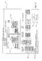
- FIG. 1shows a first embodiment of a printing/proofing system arrangement
- FIG. 2shows a flow diagram of a method for operating a printing system in accordance with the invention
- FIG. 3shows one embodiment of a user interface
- FIG. 4shows another embodiment of a user interface
- FIG. 5shows a flow diagram of another embodiment of a method for operating a printer.
- a method for printing an image on a receiver mediumis provided.
- digital image data representing an image to be printedis received and a print engine is used to print an image on the receiver medium based upon the digital image data and initial printing settings.
- a press sheet imageis captured of the image printed on the receiver medium and a virtual press sheet image is generated based upon the press sheet image said generating including the step of adapting the press sheet image to remove any artifacts induced by the manner in which the press sheet image is captured.
- the digital image datato form a virtual proof image having an appearance that reflects the anticipated appearance of an image printed on the receiver medium by the print engine based upon the digital image data and, automatically comparing the appearance of the virtual press sheet image and the appearance of the virtual proof image to detect differences.
- a method for printing an image on a receiver mediumis provided.
- digital image data representing an image to be printedis received and, a print engine is used to print an image on the receiver medium based upon the digital image data and initial printing settings.
- a press sheet imageis captured of the image printed on the receiver medium and the press sheet image is automatically compared to the digital image data to detect differences between the appearance of the image represented by the digital image data and the appearance of the press sheet image.
- Differencesare identified that reflect at least one of the presence of an image artifact introduced by the process used to capture the press sheet image, any detected difference introduced by the way in which a properly operating print engine converts digital image data into a printed image on a reference receiver medium or any detected difference introduced by a difference in the way in which a particular type of receiver medium responds to printing by the print engine and the way in which the reference receiver medium reacts to the same printing by the print engine.
- An output signalis generated based upon the detected differences and the identified differences.
- a system for printing images on a receiver mediumcomprises: a print engine to print an image on the receiver medium based upon digital image data, said printing being performed in accordance with initial printing settings; an image capture system adapted to capture a digital image of the receiver medium after an image has been printed thereon, and to generate captured image data reflecting the appearance of the image on the receiver medium; a processor adapted to cause the print engine to print the image on the receiver medium, to cause the image capture system to capture an image of the press sheet, and to convert captured image data into a virtual press sheet image by adapting captured image data to remove any artifacts introduced by the image capture system; a source of a virtual proof, said virtual proof being formed by adapting the digital image data to reflect known characteristics of the way in which the print engine converts digital image data into images to be formed on a receiver medium and by further adapting the digital image data to reflect known characteristics of a receiver medium upon which a press sheet is to be printed using the digital image data; and a comparator adapted
- FIG. 1shows a first embodiment of a printer 20 of the invention.
- printer 20comprises a housing 21 having a print engine 22 that applies markings or otherwise forms an image on a receiver medium 24 .
- Print engine 22can record images on receiver medium 24 using a variety of known technologies including, but not limited to, conventional four color offset separation printing or other contact printing, silk screening, dry electrophotography such as is used in the NexPress 2100 printer sold by Eastman Kodak Company, Rochester, N.Y., USA, thermal printing technology, drop on demand ink jet technology and continuous inkjet technology.
- print engine 22will be described as being of a type that generates color images. However, it will be appreciated that this is not necessary and that the claimed methods and apparatuses herein can be practiced with a print engine 22 , monotone images such as black and white, grayscale or sepia toned images.
- a medium advance 26is used to position a receiver medium 24 and/or print engine 22 relative to each other to facilitate recording of an image on receiver medium 24 .
- Medium advance 26can comprise any number of well-known systems for moving receiver medium 24 within printer 20 , including motor 28 driving pinch rollers 30 , a motorized platen roller (not shown) or other well-known systems for the movement of paper or other types of receiver medium 24 .
- Medium advance 26is also used to position a receiver medium 24 relative to an image capture system 32 after an image has been printed on the receiver medium 24 by print engine 22 .
- Print engine 22 , medium advance 26 and image capture system 32are operated by a processor 34 .
- Processor 34can include but is not limited to a programmable digital computer, a programmable microprocessor, a programmable logic processor, a series of electronic circuits, a series of electronic circuits reduced to the form of an integrated circuit, or a series of discrete components.
- Processor 34operates printer 20 based upon input signals from a user input system 36 , sensors 38 , a memory 40 and a communication system 54 .
- User input system 36can comprise any form of transducer or other device capable of receiving an input from a user and converting this input into a form that can be used by processor 34 .
- user input system 36can comprise a touch screen input, a touch pad input, a 4-way switch, a 6-way switch, an 8-way switch, a stylus system, a trackball system, a joystick system, a voice recognition system, a gesture recognition system or other such systems.
- Sensors 38are optional and can include light sensors and other sensors known in the art that can be used to detect conditions in the environment surrounding image capture system 32 and to convert this information into a form that can be used by processor 34 in governing operation of print engine 22 , image capture system 32 and/or other systems of print 20 .
- Sensors 38can include audio sensors adapted to capture sounds.
- Sensors 38can also include positioning and other sensors used internally to control printer operations.
- Memory 40can include conventional memory devices including solid state, magnetic, optical or other data storage devices. Memory 40 can be fixed within printer 20 or it can be removable. In the embodiment of FIG. 1 , printer 20 is shown having a hard drive 42 , a disk drive 44 for a removable disk such as an optical, magnetic or other disk memory (not shown) and a memory card slot 46 that holds a removable memory 48 such as a removable memory card and has a removable memory interface 50 for communicating with removable memory 48 . Data including but not limited to control programs, digital images and metadata can also be stored in a remote memory system 52 that is external to image capture system 32 such as a personal computer, computer network or other digital system.
- a remote memory system 52that is external to image capture system 32 such as a personal computer, computer network or other digital system.
- printer 20has a communication system 54 for communicating with a remote memory system 52 , a remote display 56 , remote input 58 , local display 66 , and/or a local input 68 .
- Communication system 54can be for example, an optical, radio frequency or transducer circuit or other system that converts image and other data into a form that can be conveyed to a remote device such as remote memory system 52 or remote display device 56 by way of an optical signal, radio frequency signal or other form of signal.
- Communication system 54can also be used to receive a digital image and other information from a host computer or network (not shown).
- Communication system 54provides processor 34 with information and instructions from signals received thereby.
- local display 66can communicate with processor 34 without involvement of communication system 54 .
- local input 68can be a component of user input system 36 and can also provide signals to processor 34 without involvement of communication system 54 .
- FIG. 2provides a flow diagram showing one embodiment of a method for operating printer 20 of FIG. 1 .
- a print orderis received by printer 20 (step 70 ) providing instructions sufficient for processor 34 to begin a print sequence.
- Processor 34can receive a print order in a variety of ways including but not limited to a receiving entries made at user input system 36 , signals received at communication system 54 , or in response to data provided by way of memory 40 including but not limited to data provided by way of a removable memory card 48 .
- Each print ordergenerally provides information from which processor 34 can determine what image is to be printed, how the image is to be printed and the quantity of the images that are to be printed.
- the typical print orderwill provide digital image data representing the image to be printed, however, the job order may include more.
- Processor 34then begins to process the digital image data by converting the digital image data into a form that can be used by print engine 22 (step 72 ). This typically involves converting the digital image data into code values (or other data types) that represent specific colors to be printed on receiver medium 26 to form an image.
- a press sheet 64is then formed by printing a press sheet image 62 on receiver medium 24 (step 74 ) using initial printing settings.
- printing settingscan help to govern the way in which print engine 22 converts code values into colors in an image, or other aspects of the printing process, such as printing speed.
- printing settingscan also dictate aspects of maintenance of the printing process, such as when and how print engine 22 is to be adjusted and/or maintained.
- the printing settingsprovide information that processor 34 uses when processor 34 operates medium advance 26 and provides code values to print engine 22 from which print engine 22 can determine colors that are to be printed at particular locations on receiver medium 24 to form press sheet image 62 .
- Processor 34then operates medium advance 26 to move press sheet 64 to a position where press sheet 64 confronts image capture system 32 so that image capture system 32 can capture an electronic image of press sheet 64 .
- Processor 34then causes an image to be captured of press sheet 64 in the form of image data representing the appearance of image 62 on press sheet 64 (step 76 ).
- image capture system 32can comprise any of a number of conventional image capture sensors (not shown) and associated control and image processing circuits that are adapted to sense a pattern of light reflected or passed through receiver medium 24 .
- image capture system 32can comprise a charge couple device (CCD), a complimentary metal oxide sensor (CMOS), or any other electronic image sensor known to those of ordinary skill in the art.
- CCDcharge couple device
- CMOScomplimentary metal oxide sensor
- image capture system 32comprises a Time Delay Integration (TDI) camera.
- TDITime Delay Integration
- the TDI cameraallows asymmetrical sampling of press sheet image 62 and, optionally, anything else recorded on press sheet 64 with integration of image data in a direction of movement of receiver medium 24 to allow real-time image capture of a series of separate images printed on a receiver medium 24 moving past TDI camera at rates of 30 meters per second or more at full press operating speeds with improved color accuracy results.
- image capture system 32can comprise a non-TDI line camera used to obtain the image of press sheet 64 .
- Conventional two-dimensional array image sensorscan also be used for image capture system 32 .
- Image capture system 32can be positioned and defined to capture a complete image of any image 62 on any press sheet 64 .
- each press sheet 64is fully captured at the best available image capture resolution.
- imagesare captured of each press sheet 64 , however, certain portions of each press sheet 64 are captured differently.
- imagescan be captured of press sheet 64 with certain areas captured greater resolution or with specific image capture goals in mind.
- regions of interestROI can be defined within press sheet image 62 and an image captured of press sheet 64 in such regions can be performed in a manner that allows for better discrimination of features therein. This can be done by increasing resolution within such areas or by otherwise altering the scanning process so that a desired level of image detail will be available within the region of interest.
- specialized target scanningcan be used that defines a special target such as a particular text, image portion or combination of colors that should be found within a region of press sheet image 62 , and image capture of that region can be performed with special emphasis to provide a level of image information that is high enough to allow a determination to be made as to whether the target area has an appropriate appearance while also providing less image information captured from other portions of press sheet image 62 .
- Processor 34adapts the image of press sheet 64 to form a virtual press sheet image having an appearance that accurately represents the appearance of press sheet 64 (step 78 ).
- This stepcan involve any of a number of adjustments to the captured image of press sheet 64 .
- a principal purpose of such adaptationsis to remove any image artifacts induced by the manner by which an electronic image of press sheet 64 is captured. For example, depending on the way in which the press sheet image was captured, it may be necessary to correct the image to compensate for conditions in the image capture system 32 , the light used to capture the image, or any number of other factors that can influence the accuracy with which image capture system 32 captures an image of press sheet 64 .
- this problemis addressed by sub-sampling in the direction of travel of receiver medium 24 .
- Such sub-samplingcan be performed during capture using a TDI camera or it can be performed during post-capture processing by processor 34 .
- a virtual proof imageis then obtained.
- the virtual proofis formed by color managing and otherwise adjusting the digital image data (step 80 ) so that the virtual proof image has an appearance that is based upon the colors that print engine 22 has been known to print in response to particular code values on a color neutral reference receiver medium 24 such as a pure white receiver medium 24 .
- the appearance of the virtual proof imagecan also be based upon any known color interactions between the way in which, for example, a dye, toner, ink, or colorant used by print engine 22 is known to interact with a particular receiver medium 24 used to form colors on receiver medium 24 .
- the virtual proofcan be formed by adapting in like fashion the data transferred from processor 34 to print engine 22 during printing of the press sheet which, as noted above, is ultimately based upon the digital image data.
- print engine 22 and receiver medium 24can interact in other ways to form an image on receiver medium 24 , and that receiver medium 24 can interact with the dye, ink, or other colorant that will be applied by print engine 22 in various ways that will impact the apparent color of the printed image such as where receive medium 24 is adapted to form an image when subject to image exposure to light, heat, impact, or other forms of energy.
- receiver medium 24can, itself, be colored and/or textured in ways that will impact apparent color of any dyes, inks, or other colorants applied thereto by print engine 22 .
- Such effectscan be anticipated and can be used to modify the digital image data to form a virtual proof image so that a virtual press sheet image and virtual proof image can be compared accurately.
- the virtual press sheet imageis then automatically compared to the virtual proof image so that any differences between the appearance of the virtual press sheet image (step 82 ) and the appearance of the virtual proof image can be detected.
- One or both of the imagescan be normalized as necessary for this comparison. In one embodiment, this can be done by comparing the data representing the virtual press sheet image to the data representing the virtual proof image. Such comparisons can include comparing the code values in each image to detect any variation in color in the images. Other types of color analysis can be performed, for example, color differences can be detected by comparing colors and print characteristics in the image, such as solid ink density (SID), trapping, dot gain, Lab data, hue, saturation, print contrast, and/or gray balance.
- SSDsolid ink density
- comparisonscould comprise conducting a frequency analysis of the data in the images to identify areas of high-resolution image content and low-resolution image content so that the extent of the sharpness of the image recorded on the press sheet can be verified.
- comparisonscan also include comparing the expected content and shapes found in the images so that printing errors, such as failing to update text or printing improperly, can be detected.
- the automatic comparison step (step 82 )can also be used to detect image artifacts in the virtual press sheet image that are indicative of printing process anomalies including, but not limited to, unintended ink drops, line thickness variations, line sharpness, pin cushion effects, and other variations that can occur in the printing process.
- Such a comparisoncan be employed to detect conditions that are specific to certain print engine types. For example, where print engine 22 is an inkjet print engine, comparison of the virtual proof image against the virtual press sheet image can be used to detect image artifacts in the virtual press sheet that are indicative of conditions caused by non-uniform operation of inkjet heads such as:
- Still other conditions that could be detected in one or more embodiments of the invention during the comparison step (step 82 )include but are not limited to problems that can arise because of the way in which the printing job has been set up, which yield the following characteristics that can be detected by way of this comparison:
- Revised printing settingscan then be optionally determined based upon the detected differences for use in subsequent prints by the print engine (step 84 ). These revised print settings can be determined automatically based upon the type of difference detected where there are known revisions to image rendering settings that can address to a particular type of difference such as for example, changes to the code values, printing speed or other characteristics of the process of printing an image. In the above-described embodiment, problems can be resolved by automatically adjusting the printing settings.
- printing settingsincludes data or other electronic signals that can be used to signal a need to initiate such maintenance or service procedures or cause such adjustments to be made to the operation of the nozzles.
- a client, pressroom manager, or other personcan be involved in the process of determining revised printing settings.
- thisis done by presenting the virtual press sheet image and, optionally, the virtual proof to a user for example, using remote display 56 or local display 66 to present such images.
- step 86it is useful to adapt the virtual press sheet image so that the colors in the virtual press sheet image have a displayed appearance that matches the appearance of the colors printed in the press sheet image 62 (step 86 ).
- differences in operating systems, dyes or other colorants used in a display and settings for a displaycan greatly influence the manner in which the display converts code values into colors. This can cause different displays to present the same image having substantially different colors. Accordingly, a process of color profiling can be performed for each display upon which a virtual press sheet image is to be presented in order to carefully build an association between the colors that the display generates in response to selected code values.
- a virtual press sheet imagecan be formed that, when presented on the display, has colors that have the same appearance as colors on the press sheet.
- each displaycan be separately profiled with the separate profiles for each display being used to form a version of the virtual press sheet image adapted for presentation on the display. In this way, each display receives a virtual press sheet image that will accurately represent the appearance of the printed press sheet 64 when presented on the display.
- printer 20is adapted for use with a class of displays that are certified to operate within a range of parameters so that only one version of the virtual press sheet image need be generated with that version being shared with any of the displays of the class.
- the printerhas profiles for more than one display type stored in memory 40 , with processor 34 determining a display type and forming a variety of virtual press sheet images for distribution, with each virtual press sheet being adapted for presentation according to the display profile for the display to which the image is being sent.
- Each virtual press sheet imageis then transmitted to the one or more display (e.g. remote display 56 or local display 66 ) for which the virtual press sheet image has been adapted and is then presented thereon (step 88 ).
- the one or more displaye.g. remote display 56 or local display 66
- the virtual proof imagecan also be adapted for presentation on a display for comparison with the virtual press sheet image 62 , such as remote display device 56 or local display device 66 as is described above (step 90 ) and provided to the display for presentation thereon (step 92 ).
- the virtual proofcan be presented for side-by-side comparison with the virtual press sheet.
- the virtual proofcan be available for alternate presentation with the virtual press sheet, superimposed presentation or other comparative presentation with the virtual press sheet image in a manner that is useful for a user.
- FIG. 3illustrates one embodiment of a side-by-side type user interface 118 presenting a display adapted virtual press sheet image 120 and a display adapted virtual proof image 122 .
- difference informationthat helps a user to automatically detect differences between the press sheet image and the virtual proof image can be presented on the display to assist a user to better appreciate the differences between the virtual proof image and the virtual press sheet image when evaluating the virtual press sheet.
- user interface 118presents the display adapted virtual press sheet image 120 and the display adapted virtual proof image 122 with such difference information taking the form of a textural warning 124 or a graphical warning 126 .
- other information 128 characterizing other potential areas of differencescan be presented. Such information can be presented using graphic symbols, text, and markings on the virtual press sheet image, and/or the virtual press sheet so that detected differences can be highlighted for a user's consideration.
- a client and/or a pressroom managercan review the quality of press sheet image 62 printed on receiver medium 24 without actually viewing press sheet 64 and can indicate whether the client and/or pressroom manager approves or requires changes (step 96 ).
- Such indicationscan be made electronically, by providing a remote user input system 58 at remote display 56 and a local user input system 68 at local display 66 that allows a user to make a response and cause a responsive signal to be transmitted to communication system 54 of printer 20 .
- a usercan select between an edit button 130 and a “run job” button 132 .
- Such indicationscan also be made using any other means of communicating with printer 20 or with an operator of printer 20 .
- the print jobcan be executed (step 104 ), and where a need for a revised printing setting is identified manually or automatically without an approval, revised printing settings can be determined automatically (steps 84 and 100 ) and printing settings for use in subsequent image prints can be adjusted according to the revised setting (step 100 ), and further causing the process of generating one or more press sheet(s), providing the one or more virtual press sheet(s) so that comparison, approval, input and adjustment can be conducted again as necessary.
- the appearance of the press sheet image 62 on press sheet 64can vary depending upon the interaction of print engine 22 , receiver material 26 and any printing materials such as colorants, donors or other material transferred to receiver material 26 by print engine 22 .
- the prior art approach of digitally simulating the effect of requested changes to a printed imagefails to consider that such digital simulations do not compensate for the effects of such interaction, and thus the method described herein provides a more accurate representation of the effect of a requested change than the prior art which does not even suggest simulating such effects.
- the virtual press sheetmay be printed as a part of an initial subset of images intended to satisfy the print order. For example, where a print order comprises 2000 copies of a print, it may be more efficient to obtain a virtual press sheet from an initial batch of 500 images. Because image capture system 32 of the present invention is incorporated into printer 20 and is capable of scanning full pages, a set of virtual press sheet images can be obtained based upon one, some, or all of the initial batch of images.
- a user interface 118can also be provided that presents display adapted virtual press sheet images of the images printed during the execution of the print order (step 106 ), so that steps 78 - 102 can be executed during execution of the print order for use in detecting differences that arise during execution of the order.
- a status indicator 134indicates the point of the print order from which the currently presented display adapted virtual proof image 122 has been obtained.
- the virtual press sheet imagescan be compared to the virtual proof to detect conditions that may vary during a print job. For example, where a serialized number of prints are printed, the quality and correctness of the serialization data and the quality of the printing of the same can be verified throughout the batch. Similarly, conditions that can vary during the printing of the print job, such as conditions that drift or that otherwise can vary over time can be detected.
- the display of the virtual press sheetcan be made in a manner that underscores the existence of the condition to a reviewer of the virtual press sheet. This can be done in a variety of ways such as by: presenting graphical information indicating the identified differences, such as text 126 shown in FIG. 4 , or graphical information that indicate the nature of the condition, the location of the condition, and/or the extent of the condition as shown above in FIG. 4 .
- the indicationcan be selected from a predetermined set of graphical symbols used in manual image editing.
- FIG. 5shows another embodiment of a method for printing an image on a receiver medium 24 in accordance with the invention.
- a print orderis received containing digital image data representing an image to be printed (step 70 )
- the digital image datais processed for use by print engine 22 (step 72 ) and print engine 22 is used to print an image on the receiver medium based upon the digital image data and initial printing settings (step 74 ).
- a press sheet imageis then captured of the image printed on the receiver medium (step 76 ).
- the press sheet image and the image represented by the digital image dataare compared to detect differences between the appearance of the image represented by the digital image data and the appearance of the press sheet image (step 140 ).
- Such a comparisoncan be performed in a manner similar to that described above with respect to the step of comparing the virtual press sheet and the virtual proof (e.g. step 82 ).
- this comparisonmay detect differences that reflect the presence of image artifacts introduced by the process used to capture the press sheet image.
- detected differences that reflect the presence of an image artifact introduced by the process used to capture the press sheet imageinclude those differences that are created by an artifact caused by image capture conditions used in capturing the press sheet image, characteristics of an image sensor used to capture the press sheet image, image processing of the captured press sheet image, or other characteristics of the process used to capture, process or store the press sheet image.
- such a comparisonmay also detect differences introduced by the way in which a properly operating print engine converts digital image data into a printed image on a reference receiver. Examples of such differences include differences that are introduced by a change in image resolution, image color content or image size that are not called for in the digital image data but necessary for the printer engine 22 to print the image.
- comparisonsmay detect differences introduced by a difference in the way in which a particular type of receiver medium responds to printing by print engine 22 and the way in which the reference receiver medium reacts to the same printing by the print engine. Examples of this include differences caused by the texture of the receiver medium, a difference caused by the color of the receiver medium or a difference in the surface finish of the receiver medium.
- this is needis addressed by adapting the press sheet image to form a virtual press sheet image as described above and by forming a virtual proof using the digital image data as also described above and by performing the comparison step 82 using the virtual proof and virtual press sheet image.
- the comparisonis performed without first forming the virtual proof and virtual press sheet images.
- a further step of identifying detected differences that reflect the presence of an image artifact introduced by the process used to capture the press sheet image, any detected difference introduced by the way in which a properly operating print engine converts digital image data into a printed image on a reference receiver medium or any detected difference introduced by a difference in the way in which a particular type of receiver medium responds to printing by the print engine and the way in which the reference receiver medium reacts to the same printing by the print engine(step 142 ).
- An output signalis then generated based upon the detected differences and the identified differences. This can be done in a variety of ways (step 144 ).
- the output signalcan be generated to include detected differences other than the identified differences.
- the output signalcan alternatively identify both the identified and detected differences.
- the output signalcan also be used as a basis for generating a user perceptible signal that indicates which of the detected differences is among the identified differences.
- the output signalis also used for automatically determining revised printing settings (step 146 ). This can be done in a similar fashion to the step of automatically determining revised image printing settings described with reference to FIG. 2 . It will be appreciated that, in this embodiment, however, the identified differences will be excluded from use in determining the revised image printing settings.
- the press sheet imagecan be presented to a user for review. This is done, in the embodiment of FIG. 5 , by adapting the press sheet image for presentation on a display (step 148 ) which can be done in the manner described above in the embodiment of FIGS. 2-4 for adapting the a press sheet image. Further adaptations can be made to the press sheet image in order to exclude artifacts generated during the process of capturing or processing the image. The adapted press sheet image is then presented on a display (step 150 ).
- the digital image datacan be adapted for presentation on a display for user consideration (step 152 ) and can be presented thereon (step 151 ).
- steps 152can also be performed in generally the same manner that is described above for adapting the virtual press sheet image for presentation.
- Difference informationcan then be presented to help an observer of a displayed press sheet image and/or a displayed image representing the digital image data to better appreciate the differences between the images.
- This informationcan be based upon the output signal and can comprise text or graphic information as is described above with respect to FIGS. 3 and 4 .
- the remaining steps of the embodiment shown in FIG. 5are also performed in the same manner described above with reference to the embodiment of FIGS. 2-4 .
Landscapes
- Engineering & Computer Science (AREA)
- Mechanical Engineering (AREA)
- Quality & Reliability (AREA)
- Image Processing (AREA)
- Color, Gradation (AREA)
- Accessory Devices And Overall Control Thereof (AREA)
Abstract
Description
- Airflow problems can give the appearance of texture, patterning, or “wavy” lines in an area of the virtual press sheet image that are not found in the same area of the virtual proof image. These problems occur when drops of ink “clumping together” in one area and/or spread farther apart in an adjacent area.
- Dark defects appear as regions of the virtual press sheet image that are overly dark following, in print order, a dark region of the virtual press sheet. Such dark defects can be detected quickly by comparison with the virtual proof image.
- Satellite drops often create high-density artifacts in a printed image and these are typically caused by extra drops during printing, or possibly drops printing in the wrong place. However, satellite drops differ from dark defect in that they appear around high intensity text or line areas, such as edges where the image changes immediately from at or near 100% to 0% coverage.
- Pic-out problems are caused by the failure of individual drops to print. This is an opposite problem to dark defect. The drops that should have printed pick up some charge from adjacent charged drops, resulting in these drops being caught instead of printed. These anomalies appear in images as lighter or blank regions in what should have been a darker or solid area. Pic-out problems tend to occur most often near borders of coverage regions.
- Streaker problems typically take the form of a solid or intermittent line of printed ink in the print direction and can occur in any region of an image. These can occur where control of an ink jet nozzle is not adequately managed.
- Clogged jets fail to print and thus forming a line that is the color of the receiver media in the print direction in regions of an image having some amount of coverage.
- Crooked jets typically form a line that is the color of the receiver media in the print direction in regions of an image having some amount of coverage. However, a crooked jet will also typically produce a dark line adjacent to the white line where two jets are depositing drops.
- Frowning serifs appear as horizontally lines with unintended, but significant curvature.
- Banding appearance in the output.
- Color variations can occur in ink jet printing when the speed of the receiver medium is not consistent.
- Color variations that can occur at a border region between an area printed by a first array of ink jet nozzles in a print engine and an area printed by a second array of ink jet nozzles.
- Color variations that occur where the alignment of differently colored inks is not correct.
- Color-to-color bleed problems appear at points where different colored regions merge into one another causing fuzzy edges. These problems are caused by excessive ink for a given paper.
- Font artifacts can take the form of excessively small size, anti-aliasing of text, use of lossy compression on raster text, holes in text caused by ink level & diffusion.
- Trapping is the ability of an ink to transfer equally to unprinted substrate and a previously printed ink film. Unequal transfer caused by trapping can take the appearance of a non-uniform colors in an image.
- In some types of printing, when one color is to be printed immediately adjacent to another color a region of overlap is defined so as to ensure the continuity of color at the border. Where this is done incorrectly the overlap can create an artifact in the image.
- Color contamination can take the form of black dots in highlights or primary colors that are not pure.
- Plugged shadows are found in shadow regions of an image that exhibit a loss of detail and are over-dark or “muddy” looking.
- Some images may not appear to have sharp edges when printed.
- Diffusion problems create worming, patterning, and haloing around solid characters in a light background area. Caused by interaction of the diffusion algorithm with certain types of image content.
- 20 printer
- 21 housing
- 22 print engine
- 24 receiver medium
- 26 media advance
- 28 motor
- 30 pinch rollers
- 32 image capture system
- 34 processor
- 36 user input system
- 38 sensors
- 40 memory
- 42 hard drive
- 44 removable disk drive
- 46 memory card slot
- 48 removable memory
- 50 memory interface
- 52 remote memory system
- 54 communication system
- 56 remote display device
- 58 remote user input system
- 62 printed image
- 64 press sheet
- 66 local display
- 68 local display user input system
- 70 receive print order step
- 72 convert step
- 74 print step
- 76 capture image step
- 78 adjust image step
- 80 form virtual proof step
- 82 compare step
- 84 revised image printing settings determining step
- 86 generate virtual proof image
- 88 present virtual press sheet image
- 90 adapt virtual proof step
- 92 present virtual proof step
- 94 present difference information step
- 96 receiver user input step
- 98 determine revised printing settings
- 100 adjust printing settings step
- 102 approval received step
- 104 start print job step
- 106 capture image step
- 118 user interface
- 120 display adapted virtual press sheet image
- 122 display adapted virtual proof image
- 124 textural warning
- 126 graphical warning
- 128 information
- 130 edit button
- 132 run job button
- 134 status indicator
- 140 compare step
- 142 detect differences step
- 144 generate output step
- 150 determine revised printing settings step
- 152 adapt press sheet image step
- 154 present adapted press sheet image step
- 156 present differences information step
Claims (20)
Priority Applications (5)
| Application Number | Priority Date | Filing Date | Title |
|---|---|---|---|
| US11/185,392US7440123B2 (en) | 2005-07-20 | 2005-07-20 | Adaptive printing |
| CNA2006800265754ACN101228780A (en) | 2005-07-20 | 2006-07-11 | Adaptive printing |
| EP06786754AEP1915854A1 (en) | 2005-07-20 | 2006-07-11 | Adaptive printing |
| PCT/US2006/026704WO2007018890A1 (en) | 2005-07-20 | 2006-07-11 | Adaptive printing |
| JP2008522812AJP5053273B2 (en) | 2005-07-20 | 2006-07-11 | Method for printing an image on a receiving medium |
Applications Claiming Priority (1)
| Application Number | Priority Date | Filing Date | Title |
|---|---|---|---|
| US11/185,392US7440123B2 (en) | 2005-07-20 | 2005-07-20 | Adaptive printing |
Publications (2)
| Publication Number | Publication Date |
|---|---|
| US20070019216A1 US20070019216A1 (en) | 2007-01-25 |
| US7440123B2true US7440123B2 (en) | 2008-10-21 |
Family
ID=36968832
Family Applications (1)
| Application Number | Title | Priority Date | Filing Date |
|---|---|---|---|
| US11/185,392Expired - Fee RelatedUS7440123B2 (en) | 2005-07-20 | 2005-07-20 | Adaptive printing |
Country Status (5)
| Country | Link |
|---|---|
| US (1) | US7440123B2 (en) |
| EP (1) | EP1915854A1 (en) |
| JP (1) | JP5053273B2 (en) |
| CN (1) | CN101228780A (en) |
| WO (1) | WO2007018890A1 (en) |
Cited By (17)
| Publication number | Priority date | Publication date | Assignee | Title |
|---|---|---|---|---|
| US20070097435A1 (en)* | 2005-11-01 | 2007-05-03 | Canon Kabushiki Kaisha | Image processing method and image processing apparatus |
| US20070272106A1 (en)* | 2006-05-24 | 2007-11-29 | Heidelberger Druckmaschinen Ag | Method and apparatus for operating printing presses |
| US20080062443A1 (en)* | 2006-09-11 | 2008-03-13 | Olson Thor A | Apparatus and methods for selective color editing of color profiles |
| US20080062442A1 (en)* | 2006-09-11 | 2008-03-13 | Olson Thor A | Methods and apparatus for color profile editing |
| US7871145B1 (en) | 2009-07-20 | 2011-01-18 | Eastman Kodak Company | Printing method for reducing stitch error between overlapping jetting modules |
| WO2011094175A1 (en) | 2010-01-29 | 2011-08-04 | Eastman Kodak Company | Processor system with provision for automated control of processing parameters |
| US20110189600A1 (en)* | 2010-01-29 | 2011-08-04 | Lars Plumer | Method for automated control of processing parameters |
| US20110189611A1 (en)* | 2010-01-29 | 2011-08-04 | Lars Plumer | Plate recognition system for automated control of processing parameters |
| US8743424B2 (en) | 2010-06-18 | 2014-06-03 | Hewlett-Packard Development Company, L.P. | Pre-print enhancement of a raster image |
| US20140368887A1 (en)* | 2013-06-14 | 2014-12-18 | Dainippon Screen Mfg. Co., Ltd. | Image inspection device, program product, and method comparing target print page data and display page data to create differential page image attribute information |
| US20190212955A1 (en) | 2018-01-05 | 2019-07-11 | Datamax-O'neil Corporation | Methods, apparatuses, and systems for verifying printed image and improving print quality |
| US10546160B2 (en) | 2018-01-05 | 2020-01-28 | Datamax-O'neil Corporation | Methods, apparatuses, and systems for providing print quality feedback and controlling print quality of machine-readable indicia |
| US10803264B2 (en) | 2018-01-05 | 2020-10-13 | Datamax-O'neil Corporation | Method, apparatus, and system for characterizing an optical system |
| US10834283B2 (en) | 2018-01-05 | 2020-11-10 | Datamax-O'neil Corporation | Methods, apparatuses, and systems for detecting printing defects and contaminated components of a printer |
| US11150849B2 (en)* | 2018-11-09 | 2021-10-19 | Phoenix Contact Gmbh & Co. Kg | Device and method for checking the printing of an article |
| US11557032B2 (en)* | 2018-11-09 | 2023-01-17 | Phoenix Contact Gmbh & Co. Kg | Device and method for the calibrated checking of a printing on an article |
| US12118415B2 (en) | 2018-11-09 | 2024-10-15 | Phoenix Contact Gmbh & Co. Kg | Apparatus and method for printing on an article based on product data of the article |
Families Citing this family (18)
| Publication number | Priority date | Publication date | Assignee | Title |
|---|---|---|---|---|
| US7652792B2 (en) | 2006-03-15 | 2010-01-26 | Quad/Tech, Inc. | Virtual ink desk and method of using same |
| JPWO2008007746A1 (en)* | 2006-07-12 | 2009-12-10 | 三菱重工業株式会社 | Printing simulation method and apparatus for setting ink supply amount used for printing of printing machine, picture color tone control method and apparatus of printing machine, and printing machine |
| EP1916100B1 (en)* | 2006-10-26 | 2014-03-05 | Heidelberger Druckmaschinen Aktiengesellschaft | Printing plate generation for anilox printing presses |
| DE102007007447A1 (en)* | 2007-02-15 | 2008-08-28 | Man Roland Druckmaschinen Ag | Method for controlling printing processes |
| DE102007020208A1 (en)* | 2007-04-28 | 2008-10-30 | Manroland Ag | Softproofing system of a printing machine |
| DE202009010985U1 (en)* | 2009-08-17 | 2010-10-14 | Manroland Ag | Device for comparing a print copy with a simulation of a given print result |
| AU2009251147B2 (en)* | 2009-12-23 | 2012-09-06 | Canon Kabushiki Kaisha | Dynamic printer modelling for output checking |
| EP2720015A4 (en)* | 2011-06-07 | 2015-03-18 | Prosper Creative Co Ltd | MEASURING DEVICE AND SYSTEM, METHOD OF ALIGNING MEASUREMENT POSITION USING THE SAME, AND MEASURING POSITION ALIGNMENT PROGRAM |
| US9992354B2 (en)* | 2012-01-31 | 2018-06-05 | Hewlett-Packard Development Company, L.P. | Media reflectance identifiers |
| US11691413B2 (en) | 2014-06-13 | 2023-07-04 | Electronics For Imaging, Inc. | Integration of a line-scan camera on a single pass inkjet printer |
| US10513110B2 (en) | 2014-06-13 | 2019-12-24 | Electronics For Imaging, Inc. | Integration of a line-scan camera on a single pass inkjet printer |
| US9914309B2 (en)* | 2014-06-13 | 2018-03-13 | Electronics For Imaging, Inc. | Method and apparatus for single-pass failed nozzle compensation |
| WO2018199933A1 (en)* | 2017-04-25 | 2018-11-01 | Hewlett-Packard Development Company, L.P. | Determining a characteristic of a substrate |
| CN109955607B (en)* | 2017-12-14 | 2020-11-17 | 海德堡印刷机械股份公司 | Method for automatically calibrating a printing press having an image detection system by means of a computer |
| US11468554B2 (en) | 2019-10-18 | 2022-10-11 | Electronics For Imaging, Inc. | Assessing printer quality by assigning quality scores to images |
| EP3896953B1 (en)* | 2020-04-17 | 2024-05-01 | Felix Schoeller GmbH & Co. KG | Method for controlling a decorative printing process |
| US20230397843A1 (en)* | 2022-06-10 | 2023-12-14 | Covidien Lp | Informative display for non-contact patient monitoring |
| CN116662087A (en)* | 2023-05-12 | 2023-08-29 | 深圳市威立印技术有限公司 | Printer software testing system and method |
Citations (10)
| Publication number | Priority date | Publication date | Assignee | Title |
|---|---|---|---|---|
| WO2001077992A1 (en) | 2000-04-07 | 2001-10-18 | Lotsadots, Inc. | Remote print press proofing system |
| US20010048529A1 (en) | 2000-05-31 | 2001-12-06 | Fotland Richard A. | Method of image color correction |
| US6452615B1 (en) | 1999-03-24 | 2002-09-17 | Fuji Xerox Co., Ltd. | System and apparatus for notetaking with digital video and ink |
| US20020176103A1 (en) | 2001-05-23 | 2002-11-28 | Wolfgang Geissler | Apparatus and method for creating color-calibration characteristic curves and/or process-calibration characteristic curves |
| WO2002100644A1 (en) | 2001-06-11 | 2002-12-19 | Gutjahr, Alexander | Method for selecting printed materials |
| US6636332B1 (en)* | 1998-02-05 | 2003-10-21 | Eastman Kodak Company | System for reproducing images and method thereof |
| US6765691B2 (en)* | 1995-11-17 | 2004-07-20 | Fuji Photo Film Co., Ltd. | Method and apparatus for converting original image data to density data for forming an image on photosensitive material and for displaying an image on a monitor |
| US20040141192A1 (en) | 2003-01-17 | 2004-07-22 | Rodolfo Jodra | Proof-document formatting to enable full-capability remote proofing in a completely standard proofing station |
| US6801907B1 (en)* | 2000-04-10 | 2004-10-05 | Security Identification Systems Corporation | System for verification and association of documents and digital images |
| WO2004096547A2 (en) | 2003-05-02 | 2004-11-11 | Koenig & Bauer Aktiengesellschaft | System for inspecting a printed image |
Family Cites Families (8)
| Publication number | Priority date | Publication date | Assignee | Title |
|---|---|---|---|---|
| JPH10283132A (en)* | 1997-04-04 | 1998-10-23 | Canon Inc | Network print system and method, and recording medium recording network print control program |
| JP3969801B2 (en)* | 1997-08-29 | 2007-09-05 | キヤノン株式会社 | Information processing apparatus and method, and program storage medium |
| JP2000127571A (en)* | 1998-10-29 | 2000-05-09 | Dainippon Screen Mfg Co Ltd | Plateless digital printer and printing method |
| JP2000222156A (en)* | 1999-01-28 | 2000-08-11 | Sony Corp | Device and method for print output control, and computer-readable recording medium where program having print output control function is recorded |
| JP2002283681A (en)* | 2001-03-23 | 2002-10-03 | Ricoh Co Ltd | Image output system |
| JP2003008809A (en)* | 2001-06-20 | 2003-01-10 | Canon Inc | Image processing system, management method for image processing system, image processing apparatus, and information processing apparatus |
| JP3624947B2 (en)* | 2001-10-10 | 2005-03-02 | セイコーエプソン株式会社 | Printing system and method for obtaining a desired color printout |
| US7274517B2 (en)* | 2005-03-10 | 2007-09-25 | Angstrom, Inc. | Micromirror array lens with focal length gradient |
- 2005
- 2005-07-20USUS11/185,392patent/US7440123B2/ennot_activeExpired - Fee Related
- 2006
- 2006-07-11WOPCT/US2006/026704patent/WO2007018890A1/enactiveApplication Filing
- 2006-07-11CNCNA2006800265754Apatent/CN101228780A/enactivePending
- 2006-07-11JPJP2008522812Apatent/JP5053273B2/ennot_activeExpired - Fee Related
- 2006-07-11EPEP06786754Apatent/EP1915854A1/ennot_activeWithdrawn
Patent Citations (12)
| Publication number | Priority date | Publication date | Assignee | Title |
|---|---|---|---|---|
| US6765691B2 (en)* | 1995-11-17 | 2004-07-20 | Fuji Photo Film Co., Ltd. | Method and apparatus for converting original image data to density data for forming an image on photosensitive material and for displaying an image on a monitor |
| US6636332B1 (en)* | 1998-02-05 | 2003-10-21 | Eastman Kodak Company | System for reproducing images and method thereof |
| US6452615B1 (en) | 1999-03-24 | 2002-09-17 | Fuji Xerox Co., Ltd. | System and apparatus for notetaking with digital video and ink |
| WO2001077992A1 (en) | 2000-04-07 | 2001-10-18 | Lotsadots, Inc. | Remote print press proofing system |
| US6707931B2 (en) | 2000-04-07 | 2004-03-16 | Integrated Color Solutions, Inc. | Remote print press proofing system |
| US6801907B1 (en)* | 2000-04-10 | 2004-10-05 | Security Identification Systems Corporation | System for verification and association of documents and digital images |
| US20010048529A1 (en) | 2000-05-31 | 2001-12-06 | Fotland Richard A. | Method of image color correction |
| US20020176103A1 (en) | 2001-05-23 | 2002-11-28 | Wolfgang Geissler | Apparatus and method for creating color-calibration characteristic curves and/or process-calibration characteristic curves |
| WO2002100644A1 (en) | 2001-06-11 | 2002-12-19 | Gutjahr, Alexander | Method for selecting printed materials |
| US20040141192A1 (en) | 2003-01-17 | 2004-07-22 | Rodolfo Jodra | Proof-document formatting to enable full-capability remote proofing in a completely standard proofing station |
| WO2004096547A2 (en) | 2003-05-02 | 2004-11-11 | Koenig & Bauer Aktiengesellschaft | System for inspecting a printed image |
| US20060230358A1 (en) | 2003-05-02 | 2006-10-12 | Jorn Sacher | System for inspecting a printed image |
Cited By (40)
| Publication number | Priority date | Publication date | Assignee | Title |
|---|---|---|---|---|
| US20070097435A1 (en)* | 2005-11-01 | 2007-05-03 | Canon Kabushiki Kaisha | Image processing method and image processing apparatus |
| US8773686B2 (en)* | 2005-11-01 | 2014-07-08 | Canon Kabushiki Kaisha | Image processing method and image processing apparatus |
| US20070272106A1 (en)* | 2006-05-24 | 2007-11-29 | Heidelberger Druckmaschinen Ag | Method and apparatus for operating printing presses |
| US8213688B2 (en)* | 2006-05-24 | 2012-07-03 | Heidelberger Druckmaschinen Ag | Method and apparatus for operating printing presses |
| US8013871B2 (en) | 2006-09-11 | 2011-09-06 | Electronics For Imaging, Inc. | Apparatus and methods for selective color editing of color profiles |
| US20080062443A1 (en)* | 2006-09-11 | 2008-03-13 | Olson Thor A | Apparatus and methods for selective color editing of color profiles |
| US20080062442A1 (en)* | 2006-09-11 | 2008-03-13 | Olson Thor A | Methods and apparatus for color profile editing |
| US8243326B2 (en)* | 2006-09-11 | 2012-08-14 | Electronics For Imaging, Inc. | Methods and apparatus for color profile editing |
| US7871145B1 (en) | 2009-07-20 | 2011-01-18 | Eastman Kodak Company | Printing method for reducing stitch error between overlapping jetting modules |
| US8393709B2 (en) | 2009-07-20 | 2013-03-12 | Eastman Kodak Company | Printing method for reducing stitch error between overlapping jetting modules |
| US20110012949A1 (en)* | 2009-07-20 | 2011-01-20 | Enge James M | Printing method for reducing stitch error between overlapping jetting modules |
| US20110189611A1 (en)* | 2010-01-29 | 2011-08-04 | Lars Plumer | Plate recognition system for automated control of processing parameters |
| WO2011094243A1 (en) | 2010-01-29 | 2011-08-04 | Eastman Kodak Company | Method for automated control of processing parameters |
| US20110189600A1 (en)* | 2010-01-29 | 2011-08-04 | Lars Plumer | Method for automated control of processing parameters |
| US20110188066A1 (en)* | 2010-01-29 | 2011-08-04 | Lars Plumer | Processor system with provision for automated control of processing parameters |
| WO2011094175A1 (en) | 2010-01-29 | 2011-08-04 | Eastman Kodak Company | Processor system with provision for automated control of processing parameters |
| US8743424B2 (en) | 2010-06-18 | 2014-06-03 | Hewlett-Packard Development Company, L.P. | Pre-print enhancement of a raster image |
| US20140368887A1 (en)* | 2013-06-14 | 2014-12-18 | Dainippon Screen Mfg. Co., Ltd. | Image inspection device, program product, and method comparing target print page data and display page data to create differential page image attribute information |
| US8970907B2 (en)* | 2013-06-14 | 2015-03-03 | Dainippon Screen Mfg. Co., Ltd. | Image inspection device, program product, and method comparing target print page data and display page data to create differential page image attribute information |
| US10546160B2 (en) | 2018-01-05 | 2020-01-28 | Datamax-O'neil Corporation | Methods, apparatuses, and systems for providing print quality feedback and controlling print quality of machine-readable indicia |
| US11941307B2 (en) | 2018-01-05 | 2024-03-26 | Hand Held Products, Inc. | Methods, apparatuses, and systems captures image of pre-printed print media information for generating validation image by comparing post-printed image with pre-printed image and improving print quality |
| US10795618B2 (en) | 2018-01-05 | 2020-10-06 | Datamax-O'neil Corporation | Methods, apparatuses, and systems for verifying printed image and improving print quality |
| US10803264B2 (en) | 2018-01-05 | 2020-10-13 | Datamax-O'neil Corporation | Method, apparatus, and system for characterizing an optical system |
| US10834283B2 (en) | 2018-01-05 | 2020-11-10 | Datamax-O'neil Corporation | Methods, apparatuses, and systems for detecting printing defects and contaminated components of a printer |
| US10999460B2 (en) | 2018-01-05 | 2021-05-04 | Datamax-O'neil Corporation | Methods, apparatuses, and systems for detecting printing defects and contaminated components of a printer |
| US12388937B2 (en) | 2018-01-05 | 2025-08-12 | Hand Held Products, Inc. | Methods, apparatuses, and systems for detecting printing defects and contaminated components of a printer |
| US11157217B2 (en) | 2018-01-05 | 2021-10-26 | Datamax-O'neil Corporation | Methods, apparatuses, and systems for verifying printed image and improving print quality |
| US11210483B2 (en) | 2018-01-05 | 2021-12-28 | Datamax-O'neil Corporation | Method, apparatus, and system for characterizing an optical system |
| US11301646B2 (en) | 2018-01-05 | 2022-04-12 | Datamax-O'neil Corporation | Methods, apparatuses, and systems for providing print quality feedback and controlling print quality of machine readable indicia |
| US12361239B2 (en) | 2018-01-05 | 2025-07-15 | Hand Held Products, Inc. | Method, apparatus, and system for characterizing an optical system |
| US11570321B2 (en) | 2018-01-05 | 2023-01-31 | Datamax-O'neil Corporation | Methods, apparatuses, and systems for detecting printing defects and contaminated components of a printer |
| US11625203B2 (en) | 2018-01-05 | 2023-04-11 | Hand Held Products, Inc. | Methods, apparatuses, and systems for scanning pre-printed print media to verify printed image and improving print quality |
| US11893449B2 (en) | 2018-01-05 | 2024-02-06 | Datamax-O'neil Corporation | Method, apparatus, and system for characterizing an optical system |
| US11900201B2 (en) | 2018-01-05 | 2024-02-13 | Hand Held Products, Inc. | Methods, apparatuses, and systems for providing print quality feedback and controlling print quality of machine readable indicia |
| US11943406B2 (en) | 2018-01-05 | 2024-03-26 | Hand Held Products, Inc. | Methods, apparatuses, and systems for detecting printing defects and contaminated components of a printer |
| US20190212955A1 (en) | 2018-01-05 | 2019-07-11 | Datamax-O'neil Corporation | Methods, apparatuses, and systems for verifying printed image and improving print quality |
| US12073282B2 (en) | 2018-01-05 | 2024-08-27 | Datamax-O'neil Corporation | Method, apparatus, and system for characterizing an optical system |
| US12118415B2 (en) | 2018-11-09 | 2024-10-15 | Phoenix Contact Gmbh & Co. Kg | Apparatus and method for printing on an article based on product data of the article |
| US11557032B2 (en)* | 2018-11-09 | 2023-01-17 | Phoenix Contact Gmbh & Co. Kg | Device and method for the calibrated checking of a printing on an article |
| US11150849B2 (en)* | 2018-11-09 | 2021-10-19 | Phoenix Contact Gmbh & Co. Kg | Device and method for checking the printing of an article |
Also Published As
| Publication number | Publication date |
|---|---|
| JP5053273B2 (en) | 2012-10-17 |
| US20070019216A1 (en) | 2007-01-25 |
| JP2009502551A (en) | 2009-01-29 |
| CN101228780A (en) | 2008-07-23 |
| EP1915854A1 (en) | 2008-04-30 |
| WO2007018890A1 (en) | 2007-02-15 |
Similar Documents
| Publication | Publication Date | Title |
|---|---|---|
| US7440123B2 (en) | Adaptive printing | |
| US8223350B2 (en) | System and method for minimizing visibility of print defects | |
| US8223385B2 (en) | Printer job visualization | |
| US9088673B2 (en) | Image registration | |
| US7973974B2 (en) | Method, apparatus and article of manufacture for modifying printing based upon direct on-the-fly media characteristic parameters | |
| CN108885541B (en) | Image processing apparatus and image processing method | |
| US8817327B2 (en) | Printing system and correspondence relationship information creation method to match visual characteristics of different printers | |
| US20080297830A1 (en) | Printer with outsourcing capability for color copies | |
| US20220318976A1 (en) | Apparatus for inspecting defect of printed material, method, and storage medium | |
| US20190387126A1 (en) | Image inspection device and image forming apparatus | |
| US20240320819A1 (en) | Inspection apparatus, inspection system, inspection method and storage medium | |
| US7184177B2 (en) | Method, apparatus and article of manufacture for modifying printing based upon direct on-the-fly media characteristic parameters | |
| US20130144557A1 (en) | System diagnostic tools for printmaking devices | |
| US20060126106A1 (en) | System and method for remote proof printing and verification | |
| JP7608757B2 (en) | Printing inspection device and printing inspection program | |
| US7085014B2 (en) | Method, apparatus and article of manufacture using media roughness as a print parameter | |
| EP3842918B1 (en) | Defect size detection mechanism | |
| JPH0520437A (en) | Print quality evaluation method | |
| JP4793648B2 (en) | Image correction unit and image correction program | |
| JP2009206685A (en) | Image forming apparatus | |
| US20250014172A1 (en) | Inspection apparatus, inspection method, and nontransitory recording medium | |
| US20240340379A1 (en) | Inspection apparatus, inspection method, and non-transitory recording medium | |
| US12309332B2 (en) | Image inspection system for print setting correction | |
| US20230083713A1 (en) | Automated enhancement of printed documents | |
| JP2002361976A (en) | Image correction unit |
Legal Events
| Date | Code | Title | Description |
|---|---|---|---|
| AS | Assignment | Owner name:EASTMAN KODAK COMPANY, NEW YORK Free format text:ASSIGNMENT OF ASSIGNORS INTEREST;ASSIGNORS:CHODAGIRI, SYAM;ANVARI, NADER;ENGE, JAMES M.;AND OTHERS;REEL/FRAME:016802/0216;SIGNING DATES FROM 20050718 TO 20050719 | |
| AS | Assignment | Owner name:CITICORP NORTH AMERICA, INC., AS AGENT, NEW YORK Free format text:SECURITY INTEREST;ASSIGNORS:EASTMAN KODAK COMPANY;PAKON, INC.;REEL/FRAME:028201/0420 Effective date:20120215 | |
| FPAY | Fee payment | Year of fee payment:4 | |
| AS | Assignment | Owner name:WILMINGTON TRUST, NATIONAL ASSOCIATION, AS AGENT, MINNESOTA Free format text:PATENT SECURITY AGREEMENT;ASSIGNORS:EASTMAN KODAK COMPANY;PAKON, INC.;REEL/FRAME:030122/0235 Effective date:20130322 Owner name:WILMINGTON TRUST, NATIONAL ASSOCIATION, AS AGENT, Free format text:PATENT SECURITY AGREEMENT;ASSIGNORS:EASTMAN KODAK COMPANY;PAKON, INC.;REEL/FRAME:030122/0235 Effective date:20130322 | |
| AS | Assignment | Owner name:BARCLAYS BANK PLC, AS ADMINISTRATIVE AGENT, NEW YORK Free format text:INTELLECTUAL PROPERTY SECURITY AGREEMENT (SECOND LIEN);ASSIGNORS:EASTMAN KODAK COMPANY;FAR EAST DEVELOPMENT LTD.;FPC INC.;AND OTHERS;REEL/FRAME:031159/0001 Effective date:20130903 Owner name:JPMORGAN CHASE BANK, N.A., AS ADMINISTRATIVE, DELAWARE Free format text:INTELLECTUAL PROPERTY SECURITY AGREEMENT (FIRST LIEN);ASSIGNORS:EASTMAN KODAK COMPANY;FAR EAST DEVELOPMENT LTD.;FPC INC.;AND OTHERS;REEL/FRAME:031158/0001 Effective date:20130903 Owner name:BANK OF AMERICA N.A., AS AGENT, MASSACHUSETTS Free format text:INTELLECTUAL PROPERTY SECURITY AGREEMENT (ABL);ASSIGNORS:EASTMAN KODAK COMPANY;FAR EAST DEVELOPMENT LTD.;FPC INC.;AND OTHERS;REEL/FRAME:031162/0117 Effective date:20130903 Owner name:BARCLAYS BANK PLC, AS ADMINISTRATIVE AGENT, NEW YO Free format text:INTELLECTUAL PROPERTY SECURITY AGREEMENT (SECOND LIEN);ASSIGNORS:EASTMAN KODAK COMPANY;FAR EAST DEVELOPMENT LTD.;FPC INC.;AND OTHERS;REEL/FRAME:031159/0001 Effective date:20130903 Owner name:JPMORGAN CHASE BANK, N.A., AS ADMINISTRATIVE, DELA Free format text:INTELLECTUAL PROPERTY SECURITY AGREEMENT (FIRST LIEN);ASSIGNORS:EASTMAN KODAK COMPANY;FAR EAST DEVELOPMENT LTD.;FPC INC.;AND OTHERS;REEL/FRAME:031158/0001 Effective date:20130903 Owner name:EASTMAN KODAK COMPANY, NEW YORK Free format text:RELEASE OF SECURITY INTEREST IN PATENTS;ASSIGNORS:CITICORP NORTH AMERICA, INC., AS SENIOR DIP AGENT;WILMINGTON TRUST, NATIONAL ASSOCIATION, AS JUNIOR DIP AGENT;REEL/FRAME:031157/0451 Effective date:20130903 Owner name:PAKON, INC., NEW YORK Free format text:RELEASE OF SECURITY INTEREST IN PATENTS;ASSIGNORS:CITICORP NORTH AMERICA, INC., AS SENIOR DIP AGENT;WILMINGTON TRUST, NATIONAL ASSOCIATION, AS JUNIOR DIP AGENT;REEL/FRAME:031157/0451 Effective date:20130903 | |
| REMI | Maintenance fee reminder mailed | ||
| LAPS | Lapse for failure to pay maintenance fees | ||
| STCH | Information on status: patent discontinuation | Free format text:PATENT EXPIRED DUE TO NONPAYMENT OF MAINTENANCE FEES UNDER 37 CFR 1.362 | |
| FP | Lapsed due to failure to pay maintenance fee | Effective date:20161021 | |
| AS | Assignment | Owner name:KODAK REALTY, INC., NEW YORK Free format text:RELEASE BY SECURED PARTY;ASSIGNOR:JP MORGAN CHASE BANK, N.A., AS ADMINISTRATIVE AGENT;REEL/FRAME:049814/0001 Effective date:20190617 Owner name:KODAK AMERICAS, LTD., NEW YORK Free format text:RELEASE BY SECURED PARTY;ASSIGNOR:JP MORGAN CHASE BANK, N.A., AS ADMINISTRATIVE AGENT;REEL/FRAME:049814/0001 Effective date:20190617 Owner name:KODAK (NEAR EAST), INC., NEW YORK Free format text:RELEASE BY SECURED PARTY;ASSIGNOR:JP MORGAN CHASE BANK, N.A., AS ADMINISTRATIVE AGENT;REEL/FRAME:049814/0001 Effective date:20190617 Owner name:NPEC, INC., NEW YORK Free format text:RELEASE BY SECURED PARTY;ASSIGNOR:JP MORGAN CHASE BANK, N.A., AS ADMINISTRATIVE AGENT;REEL/FRAME:049814/0001 Effective date:20190617 Owner name:FAR EAST DEVELOPMENT LTD., NEW YORK Free format text:RELEASE BY SECURED PARTY;ASSIGNOR:JP MORGAN CHASE BANK, N.A., AS ADMINISTRATIVE AGENT;REEL/FRAME:049814/0001 Effective date:20190617 Owner name:FPC, INC., NEW YORK Free format text:RELEASE BY SECURED PARTY;ASSIGNOR:JP MORGAN CHASE BANK, N.A., AS ADMINISTRATIVE AGENT;REEL/FRAME:049814/0001 Effective date:20190617 Owner name:KODAK IMAGING NETWORK, INC., NEW YORK Free format text:RELEASE BY SECURED PARTY;ASSIGNOR:JP MORGAN CHASE BANK, N.A., AS ADMINISTRATIVE AGENT;REEL/FRAME:049814/0001 Effective date:20190617 Owner name:CREO MANUFACTURING AMERICA LLC, NEW YORK Free format text:RELEASE BY SECURED PARTY;ASSIGNOR:JP MORGAN CHASE BANK, N.A., AS ADMINISTRATIVE AGENT;REEL/FRAME:049814/0001 Effective date:20190617 Owner name:LASER PACIFIC MEDIA CORPORATION, NEW YORK Free format text:RELEASE BY SECURED PARTY;ASSIGNOR:JP MORGAN CHASE BANK, N.A., AS ADMINISTRATIVE AGENT;REEL/FRAME:049814/0001 Effective date:20190617 Owner name:KODAK PORTUGUESA LIMITED, NEW YORK Free format text:RELEASE BY SECURED PARTY;ASSIGNOR:JP MORGAN CHASE BANK, N.A., AS ADMINISTRATIVE AGENT;REEL/FRAME:049814/0001 Effective date:20190617 Owner name:QUALEX, INC., NEW YORK Free format text:RELEASE BY SECURED PARTY;ASSIGNOR:JP MORGAN CHASE BANK, N.A., AS ADMINISTRATIVE AGENT;REEL/FRAME:049814/0001 Effective date:20190617 Owner name:EASTMAN KODAK COMPANY, NEW YORK Free format text:RELEASE BY SECURED PARTY;ASSIGNOR:JP MORGAN CHASE BANK, N.A., AS ADMINISTRATIVE AGENT;REEL/FRAME:049814/0001 Effective date:20190617 Owner name:KODAK PHILIPPINES, LTD., NEW YORK Free format text:RELEASE BY SECURED PARTY;ASSIGNOR:JP MORGAN CHASE BANK, N.A., AS ADMINISTRATIVE AGENT;REEL/FRAME:049814/0001 Effective date:20190617 Owner name:PAKON, INC., NEW YORK Free format text:RELEASE BY SECURED PARTY;ASSIGNOR:JP MORGAN CHASE BANK, N.A., AS ADMINISTRATIVE AGENT;REEL/FRAME:049814/0001 Effective date:20190617 Owner name:KODAK AVIATION LEASING LLC, NEW YORK Free format text:RELEASE BY SECURED PARTY;ASSIGNOR:JP MORGAN CHASE BANK, N.A., AS ADMINISTRATIVE AGENT;REEL/FRAME:049814/0001 Effective date:20190617 | |
| AS | Assignment | Owner name:FAR EAST DEVELOPMENT LTD., NEW YORK Free format text:RELEASE BY SECURED PARTY;ASSIGNOR:BARCLAYS BANK PLC;REEL/FRAME:052773/0001 Effective date:20170202 Owner name:KODAK (NEAR EAST) INC., NEW YORK Free format text:RELEASE BY SECURED PARTY;ASSIGNOR:BARCLAYS BANK PLC;REEL/FRAME:052773/0001 Effective date:20170202 Owner name:KODAK AMERICAS LTD., NEW YORK Free format text:RELEASE BY SECURED PARTY;ASSIGNOR:BARCLAYS BANK PLC;REEL/FRAME:052773/0001 Effective date:20170202 Owner name:KODAK PHILIPPINES LTD., NEW YORK Free format text:RELEASE BY SECURED PARTY;ASSIGNOR:BARCLAYS BANK PLC;REEL/FRAME:052773/0001 Effective date:20170202 Owner name:EASTMAN KODAK COMPANY, NEW YORK Free format text:RELEASE BY SECURED PARTY;ASSIGNOR:BARCLAYS BANK PLC;REEL/FRAME:052773/0001 Effective date:20170202 Owner name:FPC INC., NEW YORK Free format text:RELEASE BY SECURED PARTY;ASSIGNOR:BARCLAYS BANK PLC;REEL/FRAME:052773/0001 Effective date:20170202 Owner name:LASER PACIFIC MEDIA CORPORATION, NEW YORK Free format text:RELEASE BY SECURED PARTY;ASSIGNOR:BARCLAYS BANK PLC;REEL/FRAME:052773/0001 Effective date:20170202 Owner name:QUALEX INC., NEW YORK Free format text:RELEASE BY SECURED PARTY;ASSIGNOR:BARCLAYS BANK PLC;REEL/FRAME:052773/0001 Effective date:20170202 Owner name:KODAK REALTY INC., NEW YORK Free format text:RELEASE BY SECURED PARTY;ASSIGNOR:BARCLAYS BANK PLC;REEL/FRAME:052773/0001 Effective date:20170202 Owner name:NPEC INC., NEW YORK Free format text:RELEASE BY SECURED PARTY;ASSIGNOR:BARCLAYS BANK PLC;REEL/FRAME:052773/0001 Effective date:20170202 |