US7439923B2 - Multiband antenna - Google Patents
Multiband antennaDownload PDFInfo
- Publication number
- US7439923B2 US7439923B2US11/702,791US70279107AUS7439923B2US 7439923 B2US7439923 B2US 7439923B2US 70279107 AUS70279107 AUS 70279107AUS 7439923 B2US7439923 B2US 7439923B2
- Authority
- US
- United States
- Prior art keywords
- polygons
- multiband antenna
- antenna
- curve
- straight
- Prior art date
- Legal status (The legal status is an assumption and is not a legal conclusion. Google has not performed a legal analysis and makes no representation as to the accuracy of the status listed.)
- Expired - Lifetime
Links
- 238000007493shaping processMethods0.000claimsabstractdescription7
- 238000000034methodMethods0.000claimsdescription15
- 230000000737periodic effectEffects0.000claimsdescription7
- 230000008878couplingEffects0.000claimsdescription2
- 238000010168coupling processMethods0.000claimsdescription2
- 238000005859coupling reactionMethods0.000claimsdescription2
- IRLPACMLTUPBCL-KQYNXXCUSA-N5'-adenylyl sulfateChemical compoundC1=NC=2C(N)=NC=NC=2N1[C@@H]1O[C@H](COP(O)(=O)OS(O)(=O)=O)[C@@H](O)[C@H]1OIRLPACMLTUPBCL-KQYNXXCUSA-N0.000abstractdescription5
- 230000001413cellular effectEffects0.000description9
- 239000003990capacitorSubstances0.000description5
- 230000008901benefitEffects0.000description4
- 230000004044responseEffects0.000description3
- PEZNEXFPRSOYPL-UHFFFAOYSA-N(bis(trifluoroacetoxy)iodo)benzeneChemical compoundFC(F)(F)C(=O)OI(OC(=O)C(F)(F)F)C1=CC=CC=C1PEZNEXFPRSOYPL-UHFFFAOYSA-N0.000description2
- 230000006872improvementEffects0.000description2
- 239000000463materialSubstances0.000description2
- 230000004048modificationEffects0.000description2
- 238000012986modificationMethods0.000description2
- 230000005404monopoleEffects0.000description2
- 230000008569processEffects0.000description2
- 239000000523sampleSubstances0.000description2
- 239000003989dielectric materialSubstances0.000description1
- 239000011888foilSubstances0.000description1
- 238000004519manufacturing processMethods0.000description1
- 239000002184metalSubstances0.000description1
- 239000000758substrateSubstances0.000description1
Images


Classifications
- H—ELECTRICITY
- H01—ELECTRIC ELEMENTS
- H01Q—ANTENNAS, i.e. RADIO AERIALS
- H01Q1/00—Details of, or arrangements associated with, antennas
- H01Q1/36—Structural form of radiating elements, e.g. cone, spiral, umbrella; Particular materials used therewith
- H01Q1/38—Structural form of radiating elements, e.g. cone, spiral, umbrella; Particular materials used therewith formed by a conductive layer on an insulating support
- H—ELECTRICITY
- H01—ELECTRIC ELEMENTS
- H01Q—ANTENNAS, i.e. RADIO AERIALS
- H01Q1/00—Details of, or arrangements associated with, antennas
- H01Q1/12—Supports; Mounting means
- H01Q1/22—Supports; Mounting means by structural association with other equipment or articles
- H01Q1/24—Supports; Mounting means by structural association with other equipment or articles with receiving set
- H01Q1/241—Supports; Mounting means by structural association with other equipment or articles with receiving set used in mobile communications, e.g. GSM
- H01Q1/242—Supports; Mounting means by structural association with other equipment or articles with receiving set used in mobile communications, e.g. GSM specially adapted for hand-held use
- H01Q1/243—Supports; Mounting means by structural association with other equipment or articles with receiving set used in mobile communications, e.g. GSM specially adapted for hand-held use with built-in antennas
- H—ELECTRICITY
- H01—ELECTRIC ELEMENTS
- H01Q—ANTENNAS, i.e. RADIO AERIALS
- H01Q5/00—Arrangements for simultaneous operation of antennas on two or more different wavebands, e.g. dual-band or multi-band arrangements
- H01Q5/30—Arrangements for providing operation on different wavebands
- H01Q5/307—Individual or coupled radiating elements, each element being fed in an unspecified way
- H01Q5/342—Individual or coupled radiating elements, each element being fed in an unspecified way for different propagation modes
- H01Q5/357—Individual or coupled radiating elements, each element being fed in an unspecified way for different propagation modes using a single feed point
- H—ELECTRICITY
- H01—ELECTRIC ELEMENTS
- H01Q—ANTENNAS, i.e. RADIO AERIALS
- H01Q9/00—Electrically-short antennas having dimensions not more than twice the operating wavelength and consisting of conductive active radiating elements
- H01Q9/04—Resonant antennas
- H01Q9/0407—Substantially flat resonant element parallel to ground plane, e.g. patch antenna
- H01Q9/0421—Substantially flat resonant element parallel to ground plane, e.g. patch antenna with a shorting wall or a shorting pin at one end of the element
- H—ELECTRICITY
- H01—ELECTRIC ELEMENTS
- H01Q—ANTENNAS, i.e. RADIO AERIALS
- H01Q9/00—Electrically-short antennas having dimensions not more than twice the operating wavelength and consisting of conductive active radiating elements
- H01Q9/04—Resonant antennas
- H01Q9/0407—Substantially flat resonant element parallel to ground plane, e.g. patch antenna
- H01Q9/0442—Substantially flat resonant element parallel to ground plane, e.g. patch antenna with particular tuning means
Definitions
- the present inventionrelates generally to a new family of antennas with a multiband behaviour.
- the general configuration of the antennaconsists of a multilevel structure which provides the multiband behaviour.
- a description on Multilevel Antennascan be found in Patent Publication No. WO01/22528.
- a modification of said multilevel structureis introduced such that the frequency bands of the antenna can be tuned simultaneously to the main existing wireless services.
- the modificationconsists of shaping at least one of the gaps between some of the polygons in the form of a non-straight curve.
- patent publications WO01/22528 and WO01/54225disclose some general configurations for multiband and miniature antennas, an improvement in terms of size, bandwidth and efficiency is obtained in some applications when said multilevel antennas are set according to the present invention. Such an improvement is achieved mainly due to the combination of the multilevel structure in conjunction of the shaping of the gap between at least a couple of polygons on the multilevel structure.
- the antennais loaded with some capacitive elements to finely tune the antenna frequency response.
- the antennais tuned to operate simultaneously at five bands, those bands being for instance GSM900 (or AMPS), GSM1800, PCS1900, UMTS, and the 2.4 GHz band for services such as for instance BluetoothTM, IEEE802.11b and HiperLAN.
- GSM900or AMPS
- GSM1800GSM1800
- PCS1900GSM1900
- UMTSUMTS
- 2.4 GHz bandfor services such as for instance BluetoothTM, IEEE802.11b and HiperLAN.
- the combination of said services into a single antenna deviceprovides an advantage in terms of flexibility and functionality of current and future wireless devices.
- the resulting antennacovers the major current and future wireless services, opening this way a wide range of possibilities in the design of universal, multi-purpose, wireless terminals and devices that can transparently switch or simultaneously operate within all said services.
- a multilevel structure for an antenna deviceconsists of a conducting structure including a set of polygons, all of said polygons featuring the same number of sides, wherein said polygons are electromagnetically coupled either by means of a capacitive coupling or ohmic contact, wherein the contact region between directly connected polygons is narrower than 50% of the perimeter of said polygons in at least 75% of said polygons defining said conducting multilevel structure.
- FIG. 1Some particular examples of prior-art multilevel structures for antennas are found in FIG. 1 .
- FIG. 1A thorough description on the shapes and features of multilevel antennas is disclosed in patent publication WO01/22528.
- FIG. 1 and in FIG. 2an analysis and description on the antenna behaviour is found in (J. Ollikainen, O. Kivehims, A. Toropainen, P. Vainikainen, “Internal Dual-Band Patch Antenna for Mobile Phones”, APS-2000 Millennium Conference on Antennas and Propagation, Davos, Switzerland, April 2000).
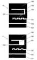
- Drawings ( 3 ) and ( 4 ) in FIG. 1are some examples of multilevel structures where the spacing between conducting polygons (rectangles and squares in these particular cases) take the form of straight, narrow gaps.
- at least one of said gapsis shaped in such a way that the whole gap length is increased yet keeping its size and the same overall antenna size.
- Such a configurationallows an effective tuning of the frequency bands of the antenna, such that with the same overall antenna size, said antenna can be effectively tuned simultaneously to some specific services, such as for instance the five frequency bands that cover the services AMPS, GSM900, GSM1800, PCS1900, UMTS, BluetoothTM, IEEE802.11b or HyperLAN.
- some specific servicessuch as for instance the five frequency bands that cover the services AMPS, GSM900, GSM1800, PCS1900, UMTS, BluetoothTM, IEEE802.11b or HyperLAN.
- FIGS. 3 to 7show some examples of how the gap of the antenna can be effectively shaped according to the present invention.
- gaps ( 109 ), ( 110 ), ( 112 ), ( 113 ), ( 114 ), ( 116 ), ( 118 ), ( 120 ), ( 130 ), ( 131 ), and ( 132 )are examples of non-straight gaps that take the form of a curved or branched line. All of them have in common that the resonant length of the multilevel structure is changed, changing this way the frequency behaviour of the antenna.
- Multiple configurationscan be chosen for shaping the gap according to the present invention:
- An Space-Filling Curve(hereafter SFC) is a curve that is large in terms of physical length but small in terms of the area in which the curve can be included. More precisely, the following definition is taken in this document for a space-filling curve: a curve composed by at least ten segments which are connected in such a way that each segment forms an angle with their neighbours, that is, no pair of adjacent segments define a larger straight segment, and wherein the curve can be optionally periodic along a fixed straight direction of space if, and only if, the period is defined by a non-periodic curve composed by at least ten connected segments and no pair of said adjacent and connected segments defines a straight longer segment.
- a space-filling curvecan be fitted over a flat or curved surface, and due to the angles between segments, the physical length of the curve is always larger than that of any straight line that can be fitted in the same area (surface) as said space-filling curve. Additionally, to properly shape the gap according to the present invention, the segments of the SFC curves included in said multilevel structure must be shorter than a tenth of the free-space operating wavelength.
- FIGS. 6 and 7describe some patch of PIFA like configurations. It is also clear that the same antenna geometry can be combined with several ground-planes and radomes to find applications in different environments: handsets, cellular phones and general handheld devices; portable computers (Palmtops, PDA, Laptops, . . . ), indoor antennas (WLAN, cellular indoor coverage), outdoor antennas for microcells in cellular environments, antennas for cars integrated in rear-view mirrors, stop-lights, bumpers and so on.
- the present inventioncan be combined with the new generation of ground-planes described in the PCT application entitled “Multilevel and Space-Filling Ground-planes for Miniature and Multiband Antennas”, which describes a ground-plane for an antenna device, comprising at least two conducting surfaces, said conducting surfaces being connected by at least a conducting strip, said strip being narrower than the width of any of said two conducting surfaces.
- FIG. 1describes four particular examples (1), (2), (3), (4) of prior-art multilevel geometries for multilevel antennas.
- FIG. 2describes a particular case of a prior-art multilevel antenna formed with eight rectangles ( 101 ), ( 102 ), ( 103 ), ( 104 ), ( 105 ), ( 106 ), ( 107 ), and ( 108 ).
- FIG. 3 drawings ( 5 ) and ( 6 )show two embodiments of the present invention. Gaps ( 109 ) and ( 110 ) between rectangles ( 102 ) and ( 104 ) of design ( 3 ) are shaped as non-straight curves ( 109 ) according to the present invention.
- FIG. 4shows three examples of embodiments (7), (8), (9) for the present invention. All three have in common that include branching gaps ( 112 ), ( 113 ), ( 114 ), ( 130 ), ( 118 ), ( 120 ).
- FIG. 5shows two particular embodiments (10) and (11) for the present invention.
- the multilevel structureconsists of a set of eight rectangles as in the case of design ( 3 ), but rectangle ( 108 ) is placed between rectangle ( 104 ) and ( 106 ).
- Non-straight, shaped gaps ( 131 ) and ( 132 )are placed between polygons ( 102 ) and ( 104 ).
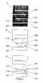
- FIG. 6shows three particular embodiments (12), (13), (14) for three complete antenna devices based on the combined multilevel and gap-shaped structure disclosed in the present invention. All three are mounted in a rectangular ground-plane such that the whole antenna device can be, for instance, integrated in a handheld or cellular phone. All three include two-loading capacitors ( 123 ) and ( 124 ) in rectangle ( 103 ), and a loading capacitor ( 124 ) in rectangle ( 101 ). All of them include two short-circuits ( 126 ) on polygons ( 101 ) and ( 103 ) and are fed by means of a pin or coaxial probe in rectangles ( 102 ) or ( 103 ).
- FIG. 7shows a particular embodiment (15) of the invention combined with a particular case of Multilevel and Space-Filling ground-plane according to the PCT application entitled “Multilevel and Space-Filling Ground-planes for Miniature and Multiband Antennas”.
- ground-plane ( 125 )is formed by two conducting surfaces ( 127 ) and ( 129 ) with a conducting strip ( 128 ) between said two conducting surfaces.
- Drawings ( 5 ) and ( 6 ) in FIG. 3show two particular embodiments of the multilevel structure and the non-linear gap according to the present invention.
- the multilevel structureis based on design ( 3 ) in FIG. 2 and it includes eight conducting rectangles: a first rectangle ( 101 ) being capacitively coupled to a second rectangle ( 102 ), said second rectangle being connected at one tip to a first tip of a third rectangle ( 103 ), said third rectangle being substantially orthogonal to said second rectangle, said third rectangle being connected at a second tip to a first tip of a fourth rectangle ( 104 ), said fourth rectangle being substantially orthogonal to said third rectangle and substantially parallel to said second rectangle, said fourth rectangle being connected at a second tip to a first tip of a fifth rectangle ( 105 ), said fifth rectangle being substantially orthogonal to said fourth rectangle and substantially parallel to said third rectangle, said fifth rectangle being connected at a second tip to a first tip of a sixth rectangle ( 106 ), said sixth rectangle being substantially orthogonal to said fifth rectangle and substantially parallel
- Both designs ( 5 ) and ( 6 )include a non-straight gap ( 109 ) and ( 110 ) respectively, between second ( 102 ) and fourth ( 104 ) polygons. It is clear that the shape of the gap and its physical length can be changed. This allows a fine tuning of the antenna to the desired frequency bands in case the conducting multilevel structure is supported by a high permittivity substrate.
- gaps ( 112 ) and ( 113 )include a main gap segment plus a minor gap-segment ( 111 ) connected to a point of said main gap segment.
- gaps ( 114 ) and ( 116 )include respectively two minor gap-segments such as ( 115 ).
- Many other branching structurescan be chosen for said gaps according to the present invention, and for instance more convoluted shapes for the minor gaps as for instance ( 117 ) and ( 119 ) included in gaps ( 118 ) and ( 120 ) in embodiment (9) are possible within the scope and spirit of the present invention.
- FIG. 3Although design in FIG. 3 has been taken as an example for embodiments in FIGS. 3 and 4 , other eight-rectangle multilevel structures, or even other multilevel structures with a different number of polygons can be used according to the present invention, as long as at least one of the gaps between two polygons is shaped as a non-straight curve.
- Another example of an eight-rectangle multilevel structureis shown in embodiments (10) and (11) in FIG. 5 . In this case, rectangle ( 108 ) is placed between rectangles ( 106 ) and ( 104 ) respectively. This contributes in reducing the overall antenna size with respect to design ( 3 ).
- Length of rectangle ( 108 )can be adjusted to finely tune the frequency response of the antenna (different lengths are shown as an example in designs ( 10 ) and ( 11 )) which is useful when adjusting the position of some of the frequency bands for future wireless services, or for instance to compensate the effective dielectric permittivity when the structure is built upon a dielectric surface.
- FIG. 6shows three examples of embodiments (12), (13), and (14) where the multilevel structure is mounted in a particular configuration as a patch antenna.
- Designs ( 5 ) and ( 7 )are chosen as a particular example, but it is obvious that any other multilevel structure can be used in the same manner as well, as for instance in the case of embodiment (14).
- a rectangular ground-plane ( 125 )is included and the antenna is placed at one end of said ground-plane.
- ground-plane geometries and positions for the multilevel structurecould be chosen, depending on the application (handsets, cellular phones and general handheld devices; portable computers such as Palmtops, PDA, Laptops, indoor antennas for WLAN, cellular indoor coverage, outdoor antennas for microcells in cellular environments, antennas for cars integrated in rear-view mirrors, stop-lights, and bumpers are some examples of possible applications) according to the present invention.
- All three embodiments (12), (13), (14)include two-loading capacitors ( 123 ) and ( 124 ) in rectangle ( 103 ), and a loading capacitor ( 124 ) in rectangle ( 101 ). All of them include two short-circuits ( 126 ) on polygons ( 101 ) and ( 103 ) and are fed by means of a pin or coaxial probe in rectangles ( 102 ) or ( 103 ). Additionally, a loading capacitor at the end of rectangle ( 108 ) can be used for the tuning of the antenna.
- Multilevel and Space-Filling Ground-planes for Miniature and Multiband Antennascan be used in combination with the present invention to further enhance the antenna device in terms of size, VSWR, bandwidth, and/or efficiency.
- FIGS. 6 and 7are similar to PIFA configurations in the sense that they include a shorting-plate or pin for a patch antenna upon a parallel ground-plane.
- the skilled in the artwill notice that the same multilevel structure including the non-straight gap can be used in the radiating elements of other possible configurations, such as for instance, monopoles, dipoles or slotted structures.
- the manufacturing process or material for the antenna deviceis not a relevant part of the invention and any process or material described in the prior-art can be used within the scope and spirit of the present invention.
- the antennacould be stamped in a metal foil or laminate; even the whole antenna structure including the multilevel structure, loading elements and ground-plane could be stamped, etched or laser cut in a single metallic surface and folded over the short-circuits to obtain, for instance, the configurations in FIGS. 6 and 7 .
- the multilevel structuremight be printed over a dielectric material (for instance FR4, Rogers®, Arlon® or Cuclad®) using conventional printing circuit techniques, or could even be deposited over a dielectric support using a two-shot injecting process to shape both the dielectric support and the conducting multilevel structure.
- a dielectric materialfor instance FR4, Rogers®, Arlon® or Cuclad®
Landscapes
- Engineering & Computer Science (AREA)
- Computer Networks & Wireless Communication (AREA)
- Waveguide Aerials (AREA)
- Support Of Aerials (AREA)
- Details Of Aerials (AREA)
Abstract
Description
This patent application is a continuation of U.S. patent application Ser. No. 10/823,257, filed on Apr. 13, 2004 now U.S. Pat. No. 7,215,287, U.S. patent application Ser. No. 10/823,257 is a continuation of PCT/EP01/011912, filed on Oct. 16, 2001. U.S. patent application Ser. No. 10/823,257 and International Application No. PCT/EP01/011912 are incorporated herein by reference.
The present invention relates generally to a new family of antennas with a multiband behaviour. The general configuration of the antenna consists of a multilevel structure which provides the multiband behaviour. A description on Multilevel Antennas can be found in Patent Publication No. WO01/22528. In the present invention, a modification of said multilevel structure is introduced such that the frequency bands of the antenna can be tuned simultaneously to the main existing wireless services. In particular, the modification consists of shaping at least one of the gaps between some of the polygons in the form of a non-straight curve.
Several configurations for the shape of said non-straight curve are allowed within the scope of the present invention. Meander lines, random curves or space-filling curves, to name some particular cases, provide effective means for conforming the antenna behaviour. A thorough description of Space-Filling curves and antennas is disclosed in patent “Space-Filling Miniature Antennas” (Patent Publication No. WO01/54225).
Although patent publications WO01/22528 and WO01/54225 disclose some general configurations for multiband and miniature antennas, an improvement in terms of size, bandwidth and efficiency is obtained in some applications when said multilevel antennas are set according to the present invention. Such an improvement is achieved mainly due to the combination of the multilevel structure in conjunction of the shaping of the gap between at least a couple of polygons on the multilevel structure. In some embodiments, the antenna is loaded with some capacitive elements to finely tune the antenna frequency response.
In some particular embodiments of the present invention, the antenna is tuned to operate simultaneously at five bands, those bands being for instance GSM900 (or AMPS), GSM1800, PCS1900, UMTS, and the 2.4 GHz band for services such as for instance Bluetooth™, IEEE802.11b and HiperLAN. There is in the prior art one example of a multilevel antenna which covers four of said services, see embodiment (3) inFIG. 1 , but there is not an example of a design which is able to integrate all five bands corresponding to those services aforementioned into a single antenna.
The combination of said services into a single antenna device provides an advantage in terms of flexibility and functionality of current and future wireless devices. The resulting antenna covers the major current and future wireless services, opening this way a wide range of possibilities in the design of universal, multi-purpose, wireless terminals and devices that can transparently switch or simultaneously operate within all said services.
The key point of the present invention consists of combining a multilevel structure for a multiband antenna together with an especial design on the shape of the gap or spacing between two polygons of said multilevel structure. A multilevel structure for an antenna device consists of a conducting structure including a set of polygons, all of said polygons featuring the same number of sides, wherein said polygons are electromagnetically coupled either by means of a capacitive coupling or ohmic contact, wherein the contact region between directly connected polygons is narrower than 50% of the perimeter of said polygons in at least 75% of said polygons defining said conducting multilevel structure. In this definition of multilevel structures, circles and ellipses are included as well, since they can be understood as polygons with a very large (ideally infinite) number of sides. Some particular examples of prior-art multilevel structures for antennas are found inFIG. 1 . A thorough description on the shapes and features of multilevel antennas is disclosed in patent publication WO01/22528. For the particular case of multilevel structure described in drawing (3),FIG. 1 and inFIG. 2 , an analysis and description on the antenna behaviour is found in (J. Ollikainen, O. Kivekäs, A. Toropainen, P. Vainikainen, “Internal Dual-Band Patch Antenna for Mobile Phones”, APS-2000 Millennium Conference on Antennas and Propagation, Davos, Switzerland, April 2000).
When the multiband behaviour of a multilevel structure is to be packed in a small antenna device, the spacing between the polygons of said multilevel structure is minimized. Drawings (3) and (4) inFIG. 1 are some examples of multilevel structures where the spacing between conducting polygons (rectangles and squares in these particular cases) take the form of straight, narrow gaps. In the present invention, at least one of said gaps is shaped in such a way that the whole gap length is increased yet keeping its size and the same overall antenna size. Such a configuration allows an effective tuning of the frequency bands of the antenna, such that with the same overall antenna size, said antenna can be effectively tuned simultaneously to some specific services, such as for instance the five frequency bands that cover the services AMPS, GSM900, GSM1800, PCS1900, UMTS, Bluetooth™, IEEE802.11b or HyperLAN.
- a) A meandering curve.
- b) A periodic curve.
- c) A branching curve, with a main longer curve with one or more added segments or branching curves departing from a point of said main longer curve.
- d) An arbitrary curve with 2 to 9 segments.
- e) An space-filling curve.
An Space-Filling Curve (hereafter SFC) is a curve that is large in terms of physical length but small in terms of the area in which the curve can be included. More precisely, the following definition is taken in this document for a space-filling curve: a curve composed by at least ten segments which are connected in such a way that each segment forms an angle with their neighbours, that is, no pair of adjacent segments define a larger straight segment, and wherein the curve can be optionally periodic along a fixed straight direction of space if, and only if, the period is defined by a non-periodic curve composed by at least ten connected segments and no pair of said adjacent and connected segments defines a straight longer segment. Also, whatever the design of such SFC is, it can never intersect with itself at any point except the initial and final point (that is, the whole curve can be arranged as a closed curve or loop, but none of the parts of the curve can become a closed loop). A space-filling curve can be fitted over a flat or curved surface, and due to the angles between segments, the physical length of the curve is always larger than that of any straight line that can be fitted in the same area (surface) as said space-filling curve. Additionally, to properly shape the gap according to the present invention, the segments of the SFC curves included in said multilevel structure must be shorter than a tenth of the free-space operating wavelength.
It is interesting noticing that, even though ideal fractal curves are mathematical abstractions and cannot be physically implemented into a real device, some particular cases of SFC can be used to approach fractal shapes and curves, and therefore can be used as well according to the scope and spirit of the present invention.
The advantages of the antenna design disclosed in the present invention are:
- (a) The antenna size is reduced with respect to: other prior-art multilevel antennas.
- (b) The frequency response of the antenna can be tuned to five frequency bands that cover the main current and future wireless services (among AMPS, GSM900, GSM1800, PCS1900, Bluetooth™, IEEE802.11b and HipeLAN).
Those skilled in the art will notice that current invention can be applied or combined to many existing prior-art antenna techniques. The new geometry can be, for instance, applied to microstrip patch antennas, to Planar Inverted-F antennas (PIFAs), to monopole antennas and so on.FIGS. 6 and 7 describe some patch of PIFA like configurations. It is also clear that the same antenna geometry can be combined with several ground-planes and radomes to find applications in different environments: handsets, cellular phones and general handheld devices; portable computers (Palmtops, PDA, Laptops, . . . ), indoor antennas (WLAN, cellular indoor coverage), outdoor antennas for microcells in cellular environments, antennas for cars integrated in rear-view mirrors, stop-lights, bumpers and so on.
In particular, the present invention can be combined with the new generation of ground-planes described in the PCT application entitled “Multilevel and Space-Filling Ground-planes for Miniature and Multiband Antennas”, which describes a ground-plane for an antenna device, comprising at least two conducting surfaces, said conducting surfaces being connected by at least a conducting strip, said strip being narrower than the width of any of said two conducting surfaces.
When combined to said ground-planes, the combined advantages of both inventions are obtained: a compact-size antenna device with an enhanced bandwidth, frequency behaviour, VSWR, and efficiency.
Drawings (5) and (6) inFIG. 3 show two particular embodiments of the multilevel structure and the non-linear gap according to the present invention. The multilevel structure is based on design (3) inFIG. 2 and it includes eight conducting rectangles: a first rectangle (101) being capacitively coupled to a second rectangle (102), said second rectangle being connected at one tip to a first tip of a third rectangle (103), said third rectangle being substantially orthogonal to said second rectangle, said third rectangle being connected at a second tip to a first tip of a fourth rectangle (104), said fourth rectangle being substantially orthogonal to said third rectangle and substantially parallel to said second rectangle, said fourth rectangle being connected at a second tip to a first tip of a fifth rectangle (105), said fifth rectangle being substantially orthogonal to said fourth rectangle and substantially parallel to said third rectangle, said fifth rectangle being connected at a second tip to a first tip of a sixth rectangle (106), said sixth rectangle being substantially orthogonal to said fifth rectangle and substantially parallel to said fourth rectangle, said sixth rectangle being connected at a second tip to a first tip of a seventh rectangle (107), said seventh rectangle being substantially orthogonal to said sixth rectangle and parallel to said fifth rectangle, said seventh rectangle being connected to a first tip of an eighth rectangle (108), said eighth rectangle being substantially orthogonal to said seventh rectangle and substantially parallel to said sixth rectangle.
Both designs (5) and (6) include a non-straight gap (109) and (110) respectively, between second (102) and fourth (104) polygons. It is clear that the shape of the gap and its physical length can be changed. This allows a fine tuning of the antenna to the desired frequency bands in case the conducting multilevel structure is supported by a high permittivity substrate.
The advantage of designs (5) and (6) with respect to prior art is that they cover five bands that include the major existing wireless and cellular systems (among AMPS, GSM900, GSM1800, PCS1900, UMTS, Bluetooth™, IEEE802.11b, HiperLAN).
Three other embodiments for the invention are shown inFIG. 4 . All three are based on design (3) but they include two shaped gaps. These two gaps are placed between rectangle (101) and rectangle (102), and between rectangle (102) and (104) respectively. In these examples, the gaps take the form of a branching structure. In embodiment (7) gaps (112) and (113) include a main gap segment plus a minor gap-segment (111) connected to a point of said main gap segment.
In embodiment (8), gaps (114) and (116) include respectively two minor gap-segments such as (115). Many other branching structures can be chosen for said gaps according to the present invention, and for instance more convoluted shapes for the minor gaps as for instance (117) and (119) included in gaps (118) and (120) in embodiment (9) are possible within the scope and spirit of the present invention.
Although design inFIG. 3 has been taken as an example for embodiments inFIGS. 3 and 4 , other eight-rectangle multilevel structures, or even other multilevel structures with a different number of polygons can be used according to the present invention, as long as at least one of the gaps between two polygons is shaped as a non-straight curve. Another example of an eight-rectangle multilevel structure is shown in embodiments (10) and (11) inFIG. 5 . In this case, rectangle (108) is placed between rectangles (106) and (104) respectively. This contributes in reducing the overall antenna size with respect to design (3). Length of rectangle (108) can be adjusted to finely tune the frequency response of the antenna (different lengths are shown as an example in designs (10) and (11)) which is useful when adjusting the position of some of the frequency bands for future wireless services, or for instance to compensate the effective dielectric permittivity when the structure is built upon a dielectric surface.
All three embodiments (12), (13), (14) include two-loading capacitors (123) and (124) in rectangle (103), and a loading capacitor (124) in rectangle (101). All of them include two short-circuits (126) on polygons (101) and (103) and are fed by means of a pin or coaxial probe in rectangles (102) or (103). Additionally, a loading capacitor at the end of rectangle (108) can be used for the tuning of the antenna.
It will be clear to those skilled in the art that the present invention can be combined in a novel way to other prior-art antenna configurations. For instance, the new generation of ground-planes disclosed in the PCT application entitled
“Multilevel and Space-Filling Ground-planes for Miniature and Multiband Antennas” can be used in combination with the present invention to further enhance the antenna device in terms of size, VSWR, bandwidth, and/or efficiency. A particular case of ground-plane (125) formed with two conducting surfaces (127) and (129), said surfaces being connected by means of a conducting strip (128), is shown as an example in embodiment (15).
The particular embodiments shown inFIGS. 6 and 7 are similar to PIFA configurations in the sense that they include a shorting-plate or pin for a patch antenna upon a parallel ground-plane. The skilled in the art will notice that the same multilevel structure including the non-straight gap can be used in the radiating elements of other possible configurations, such as for instance, monopoles, dipoles or slotted structures.
It is important to stress that the key aspect of the invention is the geometry disclosed in the present invention. The manufacturing process or material for the antenna device is not a relevant part of the invention and any process or material described in the prior-art can be used within the scope and spirit of the present invention. To name some possible examples, but not limited to them, the antenna could be stamped in a metal foil or laminate; even the whole antenna structure including the multilevel structure, loading elements and ground-plane could be stamped, etched or laser cut in a single metallic surface and folded over the short-circuits to obtain, for instance, the configurations inFIGS. 6 and 7 . Also, for instance, the multilevel structure might be printed over a dielectric material (for instance FR4, Rogers®, Arlon® or Cuclad®) using conventional printing circuit techniques, or could even be deposited over a dielectric support using a two-shot injecting process to shape both the dielectric support and the conducting multilevel structure.
Claims (50)
1. A multiband antenna comprising:
a multilevel conducting structure, substantial portions of which are formed of a plurality of first generally identifiable polygons;
said plurality of polygons including geometric elements identifiably defined by a free perimeter thereof and a projection of the longest exposed perimeter thereof to define the least number of generally identifiable polygons within a region;
at least two polygons of said plurality of polygons being interconnected by a conducting strip which is narrower in width than either one of the at least two polygons; and
wherein the at least two polygons of said plurality of polygons are separated by a non-straight gap contributing to tuning a frequency behavior of the multiband antenna.
2. The multiband antenna ofclaim 1 , wherein the plurality of polygons are selected from the group consisting of:
triangles;
quadrilaterals;
pentagons;
hexagons;
octagons;
circles; and
ellipses.
3. The multiband antenna ofclaim 1 , wherein the non-straight gap comprises at least one of:
a meandering curve;
a periodic curve;
a branching curve comprising a main longer curve and at least one added segment or branching curves departing from a point of said main longer curve;
an arbitrary curve comprising 2-9 segments; and
a space-filling curve.
4. The multiband antenna ofclaim 1 , wherein the non-straight gap comprises a plurality of second polygons, the plurality of second polygons being substantially smaller than the plurality of first generally identifiable polygons.
5. The multiband antenna ofclaim 1 , further comprising at least one capacitive element that loads the multiband antenna.
6. The multiband antenna ofclaim 1 , wherein the multiband antenna is tuned to operate simultaneously in the following frequency bands: GSM900; GSM1800; PCS1900; UMTS; and 2.4 GHz.
7. The multiband antenna ofclaim 1 , wherein select ones of adjacent polygons are coupled by ohmic contact through the conducting strip.
8. The multiband antenna ofclaim 1 , wherein the non-straight gap tunes the multiband antenna to a predetermined plurality of frequency bands.
9. The multiband antenna ofclaim 1 , wherein the non-straight gap serves to modify a resonating frequency of a plurality of resonating frequencies of the multiband antenna relative to a multiband antenna comprising an otherwise identical gap without the non-straight gap.
10. The multiband antenna ofclaim 9 , wherein the non-straight gap affects only the modified resonating frequency and not other resonating frequencies of the plurality of resonating frequencies.
11. The multiband antenna ofclaim 1 , comprising a ground plane.
12. The multiband antenna ofclaim 11 , comprising a loading element.
13. The multiband antenna ofclaim 1 , wherein the length of the sides defined between connected polygons is less than 50% of the perimeter of the polygons in at least 75% of the polygons defining the multilevel conducting structure.
14. A multiband antenna comprising:
at least one multilevel conducting structure, substantial portions of which are formed of a set of first generally identifiable polygons having an equal number of sides or faces;
said set of polygons including geometric elements identifiably defined by a free perimeter thereof and a projection of the longest exposed perimeter thereof to define the least number of generally identifiable polygons within a region;
at least two polygons of said set of polygons being coupled by a conducting strip which is narrower in width than either one of the at least two polygons; and
wherein the at least two polygons of said set of polygons are separated by a non-straight gap contributing to tuning a frequency behavior of the multiband antenna.
15. The multiband antenna ofclaim 14 , wherein the plurality of polygons are selected from the group consisting of:
triangles;
quadrilaterals;
pentagons;
hexagons;
octagons;
circles; and
ellipses.
16. The multiband antenna ofclaim 14 , wherein the non-straight gap comprises at least one of:
a meandering curve;
a periodic curve;
a branching curve comprising a main longer curve and at least one added segment or branching curves departing from a point of said main longer curve;
an arbitrary curve comprising 2-9 segments; and
a space-filling curve.
17. The multiband antenna ofclaim 14 , wherein the non-straight gap comprises a plurality of second polygons, the plurality of second polygons being substantially smaller than the plurality of first generally identifiable polygons.
18. The multiband antenna ofclaim 14 , further comprising at least one capacitive element that loads the multiband antenna.
19. The multiband antenna ofclaim 14 , wherein the multiband antenna is tuned to operate simultaneously in the following frequency bands: GSM900; GSM1800; PCS1900; UMTS; and 2.4 GHz.
20. The multiband antenna ofclaim 14 , wherein select ones of adjacent polygons are coupled by ohmic contact through the conducting strip.
21. The multiband antenna ofclaim 14 , wherein the non-straight gap tunes the multiband antenna to a predetermined plurality of frequency bands.
22. The multiband antenna ofclaim 14 , wherein the non-straight gap serves to modify a resonating frequency of a plurality of resonating frequencies of the multiband antenna relative to a multiband antenna comprising an otherwise identical gap without the non-straight gap.
23. The multiband antenna ofclaim 22 , wherein the non-straight gap affects only the modified resonating frequency and not other resonating frequencies of the plurality of resonating frequencies.
24. The multiband antenna ofclaim 14 , comprising a ground plane.
25. The multiband antenna ofclaim 24 , comprising a loading element.
26. A multiband antenna having a multilevel conducting structure constructed with a plurality of polygons having multiple exposed and connected sides, with the connected sides forming contact regions between at least two generally identifiable polygons, the multilevel conducting structure comprising:
at least two polygons electromagnetically coupled one to the other through one or both of exposed and connected sides, with each of the at least two polygons having the same number of sides;
sides of the polygons along a contact region being defined by the projection of the longest exposed side extending into the contact region of connected polygons; and
the at least two polygons being separated by a non-straight gap contributing to tuning a frequency behavior of the multiband antenna.
27. The multiband antenna ofclaim 26 , wherein the plurality of polygons are selected from the group consisting of:
triangles;
quadrilaterals;
pentagons;
hexagons;
octagons;
circles; and
ellipses.
28. The multiband antenna ofclaim 26 , wherein the non-straight gap comprises at least one of:
a meandering curve;
a periodic curve;
a branching curve comprising a main longer curve and at least one added segment or branching curves departing from a point of said main longer curve;
an arbitrary curve comprising 2-9 segments; and
a space-filling curve.
29. The multiband antenna ofclaim 26 , further comprising at least one capacitive element that loads the multiband antenna.
30. The multiband antenna ofclaim 26 , wherein the multiband antenna is tuned to operate simultaneously in the following frequency bands: GSM900; GSM1800; PCS1900; UMTS; and 2.4 GHz.
31. The multiband antenna ofclaim 26 , wherein a first polygon and a second polygon are electromagnetically coupled by ohmic contact.
32. The multiband antenna ofclaim 26 , wherein the non-straight gap tunes the multiband antenna to a predetermined plurality of frequency bands.
33. The multiband antenna ofclaim 26 , comprising a third polygon having the same number of sides as a first polygon and a second polygon and electromagnetically coupled to at least one of the first polygon and the second polygon.
34. The multiband antenna ofclaim 26 , wherein the non-straight gap serves to modify a resonating frequency of a plurality of resonating frequencies of the multiband antenna relative to a multiband antenna comprising an otherwise identical gap without the non-straight gap.
35. The multiband antenna ofclaim 34 , wherein the non-straight gap affects only the modified resonating frequency and not other resonating frequencies of the plurality of resonating frequencies.
36. The multiband antenna ofclaim 26 , comprising a ground plane.
37. The multiband antenna ofclaim 36 , comprising a loading element.
38. The multiband antenna ofclaim 26 , wherein the length of the sides defined between connected polygons is less than 50% of the perimeter of the polygons in at least 75% of the polygons defining the multilevel conducting structure.
39. An antenna-tuning method comprising:
designing a multiband antenna having a multilevel conducting structure constructed with a plurality of generally identifiable polygons having multiple exposed and connected sides;
forming, via the connected sides, a contact region between at least two polygons;
electromagnetically coupling, via one or both of exposed and connected sides, the at least two polygons, each of the at least two polygons having the same number of sides;
tuning a frequency behavior of the multiband antenna, the tuning step comprising shaping a gap between the at least two polygons in the form of a non-straight curve without altering the overall size of the multiband antenna; and
wherein the shaping step comprises modifying a resonating frequency of a plurality of resonating frequencies of the multiband antenna relative to a multiband antenna comprising an otherwise identical gap without the non-straight curve.
40. The antenna-tuning method ofclaim 39 , wherein the non-straight curve comprises at least one of:
a meandering curve;
a periodic curve;
a branching curve comprising a main longer curve and at least one added segment or branching curves departing from a point of said main longer curve;
an arbitrary curve comprising 2-9 segments; and
a space-filling curve.
41. The antenna-tuning method ofclaim 39 , further comprising loading the multiband antenna with at least one capacitive element.
42. The antenna-tuning method ofclaim 39 , wherein the multiband antenna is tuned to operate simultaneously in the following frequency bands: GSM900; GSM1800; PCS1900; UMTS; and 2.4 GHz.
43. The antenna-tuning method ofclaim 39 , wherein the plurality of polygons are selected from the group consisting of:
triangles;
quadrilaterals;
pentagons;
hexagons;
octagons;
circles; and
ellipses.
44. The antenna-tuning method ofclaim 39 , wherein a first polygon and a second polygon are electromagnetically coupled by ohmic contact.
45. The antenna-tuning method ofclaim 39 , wherein the shaped gap tunes the multiband antenna to a predetermined plurality of frequency bands.
46. The antenna-tuning method ofclaim 39 , wherein the non-straight curve affects only the modified resonating frequency and not other resonating frequencies of the plurality of resonating frequencies.
47. The antenna-tuning method ofclaim 39 , wherein sides of the plurality of polygons along the contact region are defined by the projection of the longest exposed side extending from the contact region of connected polygons.
48. The antenna-tuning method ofclaim 39 , wherein the length of the sides defined between connected polygons is less than 50% of the perimeter of the polygons in at least 75% of the polygons defining the multilevel conducting structure.
49. A multiband antenna comprising:
at least one multilevel conducting structure, substantial portions of which include at least one antenna region comprising a plurality of first generally identifiable polygons;
said plurality of polygons including geometric elements identifiably defined by a free perimeter thereof and a projection of the longest exposed perimeter thereof to define the least number of generally identifiable polygons within a region;
at least two polygons of said plurality of polygons being interconnected by a conducting strip which is narrower in width than either one of the at least two polygons; and
wherein the at least two polygons of said plurality of polygons are separated by a non-straight gap contributing to tuning a frequency behavior of the multiband antenna.
50. An antenna-tuning method comprising:
designing a multiband antenna having a multilevel conducting structure;
forming substantial portions of the multilevel conducting structure with a plurality of first generally identifiable polygons, said plurality of polygons including geometric elements identifiably defined by a free perimeter thereof and a projection of the longest exposed perimeter thereof to define the least number of generally identifiable polygons within a region;
interconnecting at least two polygons of said plurality of polygons with a conducting strip which is narrower in width than either one of the at least two polygons; and
tuning a frequency behavior of the multiband antenna through shaping of a gap between the at least two polygons of said plurality of polygons in the form of a non-straight curve without altering the overall size of the multiband antenna.
Priority Applications (4)
| Application Number | Priority Date | Filing Date | Title |
|---|---|---|---|
| US11/702,791US7439923B2 (en) | 2001-10-16 | 2007-02-06 | Multiband antenna |
| US12/229,483US7920097B2 (en) | 2001-10-16 | 2008-08-22 | Multiband antenna |
| US12/910,016US8228245B2 (en) | 2001-10-16 | 2010-10-22 | Multiband antenna |
| US13/532,869US8723742B2 (en) | 2001-10-16 | 2012-06-26 | Multiband antenna |
Applications Claiming Priority (4)
| Application Number | Priority Date | Filing Date | Title |
|---|---|---|---|
| PCT/EP2001/011912WO2003034544A1 (en) | 2001-10-16 | 2001-10-16 | Multiband antenna |
| EPPCT/EP01/11912 | 2001-10-16 | ||
| US10/823,257US7215287B2 (en) | 2001-10-16 | 2004-04-13 | Multiband antenna |
| US11/702,791US7439923B2 (en) | 2001-10-16 | 2007-02-06 | Multiband antenna |
Related Parent Applications (1)
| Application Number | Title | Priority Date | Filing Date |
|---|---|---|---|
| US10/823,257ContinuationUS7215287B2 (en) | 2001-10-16 | 2004-04-13 | Multiband antenna |
Related Child Applications (1)
| Application Number | Title | Priority Date | Filing Date |
|---|---|---|---|
| US12/229,483ContinuationUS7920097B2 (en) | 2001-10-16 | 2008-08-22 | Multiband antenna |
Publications (2)
| Publication Number | Publication Date |
|---|---|
| US20070132658A1 US20070132658A1 (en) | 2007-06-14 |
| US7439923B2true US7439923B2 (en) | 2008-10-21 |
Family
ID=8164629
Family Applications (5)
| Application Number | Title | Priority Date | Filing Date |
|---|---|---|---|
| US10/823,257Expired - LifetimeUS7215287B2 (en) | 2001-10-16 | 2004-04-13 | Multiband antenna |
| US11/702,791Expired - LifetimeUS7439923B2 (en) | 2001-10-16 | 2007-02-06 | Multiband antenna |
| US12/229,483Expired - Fee RelatedUS7920097B2 (en) | 2001-10-16 | 2008-08-22 | Multiband antenna |
| US12/910,016Expired - Fee RelatedUS8228245B2 (en) | 2001-10-16 | 2010-10-22 | Multiband antenna |
| US13/532,869Expired - Fee RelatedUS8723742B2 (en) | 2001-10-16 | 2012-06-26 | Multiband antenna |
Family Applications Before (1)
| Application Number | Title | Priority Date | Filing Date |
|---|---|---|---|
| US10/823,257Expired - LifetimeUS7215287B2 (en) | 2001-10-16 | 2004-04-13 | Multiband antenna |
Family Applications After (3)
| Application Number | Title | Priority Date | Filing Date |
|---|---|---|---|
| US12/229,483Expired - Fee RelatedUS7920097B2 (en) | 2001-10-16 | 2008-08-22 | Multiband antenna |
| US12/910,016Expired - Fee RelatedUS8228245B2 (en) | 2001-10-16 | 2010-10-22 | Multiband antenna |
| US13/532,869Expired - Fee RelatedUS8723742B2 (en) | 2001-10-16 | 2012-06-26 | Multiband antenna |
Country Status (3)
| Country | Link |
|---|---|
| US (5) | US7215287B2 (en) |
| EP (2) | EP1942551A1 (en) |
| WO (1) | WO2003034544A1 (en) |
Cited By (3)
| Publication number | Priority date | Publication date | Assignee | Title |
|---|---|---|---|---|
| US20080246689A1 (en)* | 2007-04-06 | 2008-10-09 | Hong Fu Jin Precision Industry (Shenzhen) Co., Ltd. | Mimo antenna |
| US20150263434A1 (en) | 2013-03-15 | 2015-09-17 | SeeScan, Inc. | Dual antenna systems with variable polarization |
| US10608348B2 (en) | 2012-03-31 | 2020-03-31 | SeeScan, Inc. | Dual antenna systems with variable polarization |
Families Citing this family (36)
| Publication number | Priority date | Publication date | Assignee | Title |
|---|---|---|---|---|
| MXPA04002384A (en) | 2001-09-13 | 2004-05-31 | Fractus Sa | Multilevel and space-filling ground-planes for miniature and multiband antennas. |
| CN100382385C (en) | 2001-10-16 | 2008-04-16 | 弗拉克托斯股份有限公司 | load antenna |
| US9755314B2 (en) | 2001-10-16 | 2017-09-05 | Fractus S.A. | Loaded antenna |
| AU2002319262A1 (en) | 2002-06-25 | 2004-01-06 | Fractus, S.A. | Multiband antenna for handheld terminal |
| EP2273611B1 (en) | 2002-12-22 | 2012-02-08 | Fractus, S.A. | Multi-band monopole antenna for a mobile communications device |
| EP1709704A2 (en) | 2004-01-30 | 2006-10-11 | Fractus, S.A. | Multi-band monopole antennas for mobile communications devices |
| GB0407901D0 (en)* | 2004-04-06 | 2004-05-12 | Koninkl Philips Electronics Nv | Improvements in or relating to planar antennas |
| FI20040584A7 (en)* | 2004-04-26 | 2005-10-27 | Pulse Finland Oy | Antenna element and method for manufacturing the same |
| DE602005002697T2 (en) | 2004-08-21 | 2008-01-24 | Samsung Electronics Co., Ltd., Suwon | Small planar antenna with increased bandwidth and small strip antenna |
| WO2006032455A1 (en) | 2004-09-21 | 2006-03-30 | Fractus, S.A. | Multilevel ground-plane for a mobile device |
| US7932863B2 (en) | 2004-12-30 | 2011-04-26 | Fractus, S.A. | Shaped ground plane for radio apparatus |
| WO2006097496A1 (en) | 2005-03-15 | 2006-09-21 | Fractus, S.A. | Slotted ground-plane used as a slot antenna or used for a pifa antenna |
| KR100689475B1 (en)* | 2005-04-27 | 2007-03-02 | 삼성전자주식회사 | Built-in antenna device of mobile terminal |
| EP1878088B1 (en)* | 2005-04-27 | 2018-06-06 | Qualcomm Technologies, Inc. | Radio device having antenna arrangement suited for operating over a plurality of bands. |
| FR2911998B1 (en)* | 2007-01-31 | 2010-08-13 | St Microelectronics Sa | BROADBAND ANTENNA |
| US20090124215A1 (en)* | 2007-09-04 | 2009-05-14 | Sierra Wireless, Inc. | Antenna Configurations for Compact Device Wireless Communication |
| US20090122847A1 (en)* | 2007-09-04 | 2009-05-14 | Sierra Wireless, Inc. | Antenna Configurations for Compact Device Wireless Communication |
| TWI347710B (en)* | 2007-09-20 | 2011-08-21 | Delta Networks Inc | Multi-mode resonator broadband antenna |
| US20090229108A1 (en)* | 2008-03-17 | 2009-09-17 | Ethertronics, Inc. | Methods for forming antennas using thermoforming |
| USD611038S1 (en)* | 2008-08-21 | 2010-03-02 | Panasonic Corporation | Antenna |
| USD608770S1 (en)* | 2008-08-21 | 2010-01-26 | Panasonic Corporation | Antenna |
| USD611039S1 (en)* | 2008-08-21 | 2010-03-02 | Panasonic Corporation | Antenna |
| US20100134358A1 (en)* | 2008-12-01 | 2010-06-03 | Cheng Uei Precision Industry Co., Ltd | Multi-Band Antenna |
| TWI466377B (en)* | 2009-01-13 | 2014-12-21 | Realtek Semiconductor Corp | Multi-band printed antenna |
| KR101007390B1 (en)* | 2010-03-02 | 2011-01-13 | 삼성탈레스 주식회사 | Antenna device for mobile terminal |
| TWI450443B (en) | 2010-10-20 | 2014-08-21 | Wistron Corp | Antenna |
| GB201122324D0 (en) | 2011-12-23 | 2012-02-01 | Univ Edinburgh | Antenna element & antenna device comprising such elements |
| CN103855461B (en)* | 2012-12-06 | 2016-05-11 | 瑞声声学科技(深圳)有限公司 | Antenna |
| AU356356S (en)* | 2014-05-08 | 2014-07-10 | A passive EM antenna for an electronic device | |
| AU356359S (en)* | 2014-06-12 | 2014-07-10 | Passive EM antenna for android smart phones - 2 | |
| EP3285333A1 (en) | 2016-08-16 | 2018-02-21 | Institut Mines Telecom / Telecom Bretagne | Configurable multiband antenna arrangement and design method thereof |
| EP3340379A1 (en) | 2016-12-22 | 2018-06-27 | Institut Mines Telecom / Telecom Bretagne | Configurable multiband antenna arrangement with wideband capacity and design method thereof |
| EP3503293B1 (en) | 2017-12-19 | 2024-12-11 | Institut Mines Telecom - IMT Atlantique - Bretagne - Pays de la Loire | Configurable multiband wire antenna arrangement and design method thereof |
| EP3503294A1 (en) | 2017-12-22 | 2019-06-26 | Institut Mines Telecom - IMT Atlantique - Bretagne - Pays de la Loire | Configurable multiband antenna arrangement with a multielement structure and design method thereof |
| EP3591761A1 (en) | 2018-07-06 | 2020-01-08 | Institut Mines Telecom - IMT Atlantique - Bretagne - Pays de la Loire | Multiband antenna arrangement built to a specification from a library of basic elements |
| US12149012B1 (en) | 2024-04-11 | 2024-11-19 | Geotab Inc. | Multi-band antenna device and tuning techniques |
Citations (199)
| Publication number | Priority date | Publication date | Assignee | Title |
|---|---|---|---|---|
| US3521284A (en) | 1968-01-12 | 1970-07-21 | John Paul Shelton Jr | Antenna with pattern directivity control |
| US3599214A (en) | 1969-03-10 | 1971-08-10 | New Tronics Corp | Automobile windshield antenna |
| US3622890A (en) | 1968-01-31 | 1971-11-23 | Matsushita Electric Industrial Co Ltd | Folded integrated antenna and amplifier |
| US3683376A (en) | 1970-10-12 | 1972-08-08 | Joseph J O Pronovost | Radar antenna mount |
| US3818490A (en) | 1972-08-04 | 1974-06-18 | Westinghouse Electric Corp | Dual frequency array |
| US3967276A (en) | 1975-01-09 | 1976-06-29 | Beam Guidance Inc. | Antenna structures having reactance at free end |
| US3969730A (en) | 1975-02-12 | 1976-07-13 | The United States Of America As Represented By The Secretary Of Transportation | Cross slot omnidirectional antenna |
| US4024542A (en) | 1974-12-25 | 1977-05-17 | Matsushita Electric Industrial Co., Ltd. | Antenna mount for receiver cabinet |
| US4131893A (en) | 1977-04-01 | 1978-12-26 | Ball Corporation | Microstrip radiator with folded resonant cavity |
| US4141016A (en) | 1977-04-25 | 1979-02-20 | Antenna, Incorporated | AM-FM-CB Disguised antenna system |
| JPS55147806U (en) | 1979-04-07 | 1980-10-24 | ||
| US4471358A (en) | 1963-04-01 | 1984-09-11 | Raytheon Company | Re-entry chaff dart |
| US4471493A (en) | 1982-12-16 | 1984-09-11 | Gte Automatic Electric Inc. | Wireless telephone extension unit with self-contained dipole antenna |
| US4504834A (en) | 1982-12-22 | 1985-03-12 | Motorola, Inc. | Coaxial dipole antenna with extended effective aperture |
| DE3337941A1 (en) | 1983-10-19 | 1985-05-09 | Bayer Ag, 5090 Leverkusen | Passive radar reflectors |
| FR2543744B3 (en) | 1983-04-01 | 1985-08-09 | Icma Spa | ANTENNA FOR AUTO-RADIO |
| US4543581A (en) | 1981-07-10 | 1985-09-24 | Budapesti Radiotechnikai Gyar | Antenna arrangement for personal radio transceivers |
| US4571595A (en) | 1983-12-05 | 1986-02-18 | Motorola, Inc. | Dual band transceiver antenna |
| US4584709A (en) | 1983-07-06 | 1986-04-22 | Motorola, Inc. | Homotropic antenna system for portable radio |
| US4590614A (en) | 1983-01-28 | 1986-05-20 | Robert Bosch Gmbh | Dipole antenna for portable radio |
| US4623894A (en) | 1984-06-22 | 1986-11-18 | Hughes Aircraft Company | Interleaved waveguide and dipole dual band array antenna |
| US4673948A (en) | 1985-12-02 | 1987-06-16 | Gte Government Systems Corporation | Foreshortened dipole antenna with triangular radiators |
| US4730195A (en) | 1985-07-01 | 1988-03-08 | Motorola, Inc. | Shortened wideband decoupled sleeve dipole antenna |
| EP0096847B1 (en) | 1982-06-16 | 1989-02-08 | DIEHL GMBH & CO. | Chaff dispensing device |
| US4839660A (en) | 1983-09-23 | 1989-06-13 | Orion Industries, Inc. | Cellular mobile communication antenna |
| US4843468A (en) | 1986-07-14 | 1989-06-27 | British Broadcasting Corporation | Scanning techniques using hierarchical set of curves |
| US4847629A (en) | 1988-08-03 | 1989-07-11 | Alliance Research Corporation | Retractable cellular antenna |
| US4849766A (en) | 1986-07-04 | 1989-07-18 | Central Glass Company, Limited | Vehicle window glass antenna using transparent conductive film |
| US4857939A (en) | 1988-06-03 | 1989-08-15 | Alliance Research Corporation | Mobile communications antenna |
| GB2215136A (en) | 1988-02-10 | 1989-09-13 | Ronald Cecil Hutchins | Broadsword anti-radar foil |
| US4890114A (en) | 1987-04-30 | 1989-12-26 | Harada Kogyo Kabushiki Kaisha | Antenna for a portable radiotelephone |
| US4894663A (en) | 1987-11-16 | 1990-01-16 | Motorola, Inc. | Ultra thin radio housing with integral antenna |
| US4907011A (en) | 1987-12-14 | 1990-03-06 | Gte Government Systems Corporation | Foreshortened dipole antenna with triangular radiating elements and tapered coaxial feedline |
| US4912481A (en) | 1989-01-03 | 1990-03-27 | Westinghouse Electric Corp. | Compact multi-frequency antenna array |
| EP0297813A3 (en) | 1987-06-27 | 1990-06-20 | Nippon Sheet Glass Co., Ltd. | A vehicle receiving apparatus using a window antenna |
| US4975711A (en) | 1988-08-31 | 1990-12-04 | Samsung Electronic Co., Ltd. | Slot antenna device for portable radiophone |
| US5030963A (en) | 1988-08-22 | 1991-07-09 | Sony Corporation | Signal receiver |
| US5138328A (en) | 1991-08-22 | 1992-08-11 | Motorola, Inc. | Integral diversity antenna for a laptop computer |
| US5168472A (en) | 1991-11-13 | 1992-12-01 | The United States Of America As Represented By The Secretary Of The Navy | Dual-frequency receiving array using randomized element positions |
| US5172084A (en) | 1991-12-18 | 1992-12-15 | Space Systems/Loral, Inc. | Miniature planar filters based on dual mode resonators of circular symmetry |
| US5200756A (en) | 1991-05-03 | 1993-04-06 | Novatel Communications Ltd. | Three dimensional microstrip patch antenna |
| US5214434A (en) | 1992-05-15 | 1993-05-25 | Hsu Wan C | Mobile phone antenna with improved impedance-matching circuit |
| EP0543645A1 (en) | 1991-11-18 | 1993-05-26 | Motorola, Inc. | Embedded antenna for communication devices |
| US5218370A (en) | 1990-12-10 | 1993-06-08 | Blaese Herbert R | Knuckle swivel antenna for portable telephone |
| US5227804A (en) | 1988-07-05 | 1993-07-13 | Nec Corporation | Antenna structure used in portable radio device |
| US5227808A (en) | 1991-05-31 | 1993-07-13 | The United States Of America As Represented By The Secretary Of The Air Force | Wide-band L-band corporate fed antenna for space based radars |
| US5245350A (en) | 1991-07-13 | 1993-09-14 | Nokia Mobile Phones (U.K.) Limited | Retractable antenna assembly with retraction inactivation |
| US5248988A (en) | 1989-12-12 | 1993-09-28 | Nippon Antenna Co., Ltd. | Antenna used for a plurality of frequencies in common |
| US5255002A (en) | 1991-02-22 | 1993-10-19 | Pilkington Plc | Antenna for vehicle window |
| US5257032A (en) | 1991-01-24 | 1993-10-26 | Rdi Electronics, Inc. | Antenna system including spiral antenna and dipole or monopole antenna |
| EP0358090B1 (en) | 1988-09-01 | 1994-08-17 | Asahi Glass Company Ltd. | Window glass for an automobile |
| US5347291A (en) | 1991-12-05 | 1994-09-13 | Moore Richard L | Capacitive-type, electrically short, broadband antenna and coupling systems |
| US5355144A (en) | 1992-03-16 | 1994-10-11 | The Ohio State University | Transparent window antenna |
| US5355318A (en) | 1992-06-02 | 1994-10-11 | Alcatel Alsthom Compagnie Generale D'electricite | Method of manufacturing a fractal object by using steriolithography and a fractal object obtained by performing such a method |
| FR2704359A1 (en) | 1993-04-23 | 1994-10-28 | Hirschmann Richard Gmbh Co | Flat antenna. |
| US5373300A (en) | 1992-05-21 | 1994-12-13 | International Business Machines Corporation | Mobile data terminal with external antenna |
| US5402134A (en) | 1993-03-01 | 1995-03-28 | R. A. Miller Industries, Inc. | Flat plate antenna module |
| WO1995011530A1 (en) | 1992-04-08 | 1995-04-27 | Wipac Group Limited | Vehicle antenna |
| US5420599A (en) | 1993-05-06 | 1995-05-30 | At&T Global Information Solutions Company | Antenna apparatus |
| US5422651A (en) | 1993-10-13 | 1995-06-06 | Chang; Chin-Kang | Pivotal structure for cordless telephone antenna |
| US5451965A (en) | 1992-07-28 | 1995-09-19 | Mitsubishi Denki Kabushiki Kaisha | Flexible antenna for a personal communications device |
| US5451968A (en) | 1992-11-19 | 1995-09-19 | Solar Conversion Corp. | Capacitively coupled high frequency, broad-band antenna |
| US5453751A (en) | 1991-04-24 | 1995-09-26 | Matsushita Electric Works, Ltd. | Wide-band, dual polarized planar antenna |
| US5471224A (en) | 1993-11-12 | 1995-11-28 | Space Systems/Loral Inc. | Frequency selective surface with repeating pattern of concentric closed conductor paths, and antenna having the surface |
| US5493702A (en) | 1993-04-05 | 1996-02-20 | Crowley; Robert J. | Antenna transmission coupling arrangement |
| US5495261A (en) | 1990-04-02 | 1996-02-27 | Information Station Specialists | Antenna ground system |
| US5534877A (en) | 1989-12-14 | 1996-07-09 | Comsat | Orthogonally polarized dual-band printed circuit antenna employing radiating elements capacitively coupled to feedlines |
| US5537367A (en) | 1994-10-20 | 1996-07-16 | Lockwood; Geoffrey R. | Sparse array structures |
| WO1996027219A1 (en) | 1995-02-27 | 1996-09-06 | The Chinese University Of Hong Kong | Meandering inverted-f antenna |
| WO1996029755A1 (en) | 1995-03-17 | 1996-09-26 | Elden, Inc. | In-vehicle antenna |
| WO1996038881A1 (en) | 1995-06-02 | 1996-12-05 | Ericsson Inc. | Multiple band printed monopole antenna |
| WO1997006578A1 (en) | 1995-08-09 | 1997-02-20 | Fractal Antenna Systems, Inc. | Fractal antennas, resonators and loading elements |
| WO1997011507A1 (en) | 1995-09-22 | 1997-03-27 | Qualcomm Incorporated | Dual-band octafilar helix antenna |
| WO1997032355A1 (en) | 1996-03-01 | 1997-09-04 | Toyota Jidosha Kabushiki Kaisha | Antenna device for vehicles |
| WO1997033338A1 (en) | 1996-03-05 | 1997-09-12 | Research In Motion Limited | Antenna for a radio telecommunications device |
| WO1997035360A1 (en) | 1996-03-22 | 1997-09-25 | Ball Aerospace & Technologies Corp. | Multi-frequency antenna |
| US5684672A (en) | 1996-02-20 | 1997-11-04 | International Business Machines Corporation | Laptop computer with an integrated multi-mode antenna |
| WO1997047054A1 (en) | 1996-06-05 | 1997-12-11 | Intercell Wireless Corporation | Dual resonance antenna for portable telephone |
| US5712640A (en) | 1994-11-28 | 1998-01-27 | Honda Giken Kogyo Kabushiki Kaisha | Radar module for radar system on motor vehicle |
| WO1998012771A1 (en) | 1996-09-18 | 1998-03-26 | Research In Motion Limited | Antenna system for an rf data communications device |
| US5767811A (en) | 1995-09-19 | 1998-06-16 | Murata Manufacturing Co. Ltd. | Chip antenna |
| JPH10209744A (en) | 1997-01-28 | 1998-08-07 | Matsushita Electric Works Ltd | Inverted f-type antenna |
| WO1998036469A1 (en) | 1997-02-18 | 1998-08-20 | Poong Jeong Industrial Co., Ltd. | Antenna device for automotive vehicle |
| US5798688A (en) | 1997-02-07 | 1998-08-25 | Donnelly Corporation | Interior vehicle mirror assembly having communication module |
| ES2112163B1 (en) | 1995-05-19 | 1998-11-16 | Univ Catalunya Politecnica | FRACTAL OR MULTIFRACTAL ANTENNAS. |
| US5841403A (en) | 1995-04-25 | 1998-11-24 | Norand Corporation | Antenna means for hand-held radio devices |
| WO1999003166A1 (en) | 1997-07-09 | 1999-01-21 | Allgon Ab | Antenna device for a hand-portable radio communication unit |
| WO1999003167A1 (en) | 1997-07-09 | 1999-01-21 | Allgon Ab | Hand-portable telephone with radiation absorbing device |
| US5867126A (en) | 1996-02-14 | 1999-02-02 | Murata Mfg. Co. Ltd | Surface-mount-type antenna and communication equipment using same |
| US5870066A (en) | 1995-12-06 | 1999-02-09 | Murana Mfg. Co. Ltd. | Chip antenna having multiple resonance frequencies |
| US5872546A (en) | 1995-09-27 | 1999-02-16 | Ntt Mobile Communications Network Inc. | Broadband antenna using a semicircular radiator |
| US5898404A (en) | 1995-12-22 | 1999-04-27 | Industrial Technology Research Institute | Non-coplanar resonant element printed circuit board antenna |
| US5903240A (en) | 1996-02-13 | 1999-05-11 | Murata Mfg. Co. Ltd | Surface mounting antenna and communication apparatus using the same antenna |
| WO1999025042A1 (en) | 1997-11-06 | 1999-05-20 | Telefonaktiebolaget Lm Ericsson | A portable electronic communication device with multi-band antenna system |
| EP0871238A3 (en) | 1997-03-25 | 1999-05-26 | Nokia Mobile Phones Ltd. | Broadband antenna realized with shorted microstrips |
| WO1999027608A1 (en) | 1997-11-22 | 1999-06-03 | Nathan Cohen | Cylindrical conformable antenna on a planar substrate |
| US5926141A (en) | 1996-08-16 | 1999-07-20 | Fuba Automotive Gmbh | Windowpane antenna with transparent conductive layer |
| US5943020A (en) | 1996-03-13 | 1999-08-24 | Ascom Tech Ag | Flat three-dimensional antenna |
| US5966097A (en) | 1996-06-03 | 1999-10-12 | Mitsubishi Denki Kabushiki Kaisha | Antenna apparatus |
| EP0814536A3 (en) | 1996-06-20 | 1999-10-13 | Kabushiki Kaisha Yokowo | Antenna and radio apparatus using same |
| US5973651A (en) | 1996-09-20 | 1999-10-26 | Murata Manufacturing Co., Ltd. | Chip antenna and antenna device |
| WO1999056345A1 (en) | 1998-04-24 | 1999-11-04 | Intenna Technology Ab | Multiple band antenna device |
| US5986610A (en) | 1995-10-11 | 1999-11-16 | Miron; Douglas B. | Volume-loaded short dipole antenna |
| US5990838A (en) | 1996-06-12 | 1999-11-23 | 3Com Corporation | Dual orthogonal monopole antenna system |
| US6002367A (en) | 1996-05-17 | 1999-12-14 | Allgon Ab | Planar antenna device |
| WO2000001028A1 (en) | 1998-06-26 | 2000-01-06 | Research In Motion Limited | Dual embedded antenna for an rf data communications device |
| WO2000003453A1 (en) | 1998-07-09 | 2000-01-20 | Telefonaktiebolaget Lm Ericsson (Publ) | Miniature printed spiral antenna for mobile terminals |
| US6028568A (en) | 1997-12-11 | 2000-02-22 | Murata Manufacturing Co., Ltd. | Chip-antenna |
| US6031499A (en) | 1998-05-22 | 2000-02-29 | Intel Corporation | Multi-purpose vehicle antenna |
| WO2000022695A1 (en) | 1998-10-12 | 2000-04-20 | Amphenol Socapex | Patch antenna |
| US6078294A (en) | 1996-03-01 | 2000-06-20 | Toyota Jidosha Kabushiki Kaisha | Antenna device for vehicles |
| WO2000036700A1 (en) | 1998-12-16 | 2000-06-22 | Telefonaktiebolaget Lm Ericsson (Publ) | Printed multi-band patch antenna |
| US6091365A (en) | 1997-02-24 | 2000-07-18 | Telefonaktiebolaget Lm Ericsson | Antenna arrangements having radiating elements radiating at different frequencies |
| US6097345A (en) | 1998-11-03 | 2000-08-01 | The Ohio State University | Dual band antenna for vehicles |
| US6104349A (en) | 1995-08-09 | 2000-08-15 | Cohen; Nathan | Tuning fractal antennas and fractal resonators |
| WO2000049680A1 (en) | 1999-02-16 | 2000-08-24 | Gentex Corporation | Rearview mirror with integrated microwave receiver |
| WO2000052787A1 (en) | 1999-03-02 | 2000-09-08 | Nederlandse Organisatie Voor Toegepast-Natuurwetenschappelijk Onderzoek Tno | Volumetric phased array antenna system |
| WO2000052784A1 (en) | 1999-03-01 | 2000-09-08 | Siemens Aktiengesellschaft | Integrable multiband antenna |
| US6127977A (en) | 1996-11-08 | 2000-10-03 | Cohen; Nathan | Microstrip patch antenna with fractal structure |
| US6131042A (en) | 1998-05-04 | 2000-10-10 | Lee; Chang | Combination cellular telephone radio receiver and recorder mechanism for vehicles |
| US6140969A (en) | 1996-10-16 | 2000-10-31 | Fuba Automotive Gmbh & Co. Kg | Radio antenna arrangement with a patch antenna |
| ES2142280B1 (en) | 1998-05-06 | 2000-11-16 | Univ Catalunya Politecnica | DUAL MULTITRIANGULAR ANTENNAS FOR CELL PHONE GSM AND DCS |
| US6160513A (en) | 1997-12-22 | 2000-12-12 | Nokia Mobile Phones Limited | Antenna |
| US6172618B1 (en) | 1998-12-07 | 2001-01-09 | Mitsubushi Denki Kabushiki Kaisha | ETC car-mounted equipment |
| WO2001003238A1 (en) | 1999-06-29 | 2001-01-11 | Siemens Aktiengesellschaft | Integrable dual-band antenna |
| WO2001008257A1 (en) | 1999-07-23 | 2001-02-01 | Avantego Ab | Antenna arrangement |
| WO2001013464A1 (en) | 1999-08-18 | 2001-02-22 | Ericsson, Inc. | A dual band bowtie/meander antenna |
| EP0932219A3 (en) | 1998-01-21 | 2001-03-07 | Filtronic LK Oy | Planar antenna |
| WO2001017064A1 (en) | 1999-08-27 | 2001-03-08 | Antennas America, Inc. | Compact planar inverted f antenna |
| WO2001022528A1 (en) | 1999-09-20 | 2001-03-29 | Fractus, S.A. | Multilevel antennae |
| US6211824B1 (en) | 1999-05-06 | 2001-04-03 | Raytheon Company | Microstrip patch antenna |
| WO2001024314A1 (en) | 1999-09-30 | 2001-04-05 | Harada Industries (Europe) Limited | Dual-band microstrip antenna |
| WO2001026182A1 (en) | 1999-10-04 | 2001-04-12 | Smarteq Wireless Ab | Antenna means |
| US6218992B1 (en) | 2000-02-24 | 2001-04-17 | Ericsson Inc. | Compact, broadband inverted-F antennas with conductive elements and wireless communicators incorporating same |
| WO2001028035A1 (en) | 1999-10-12 | 2001-04-19 | Arc Wireless Solutions, Inc. | Compact dual narrow band microstrip antenna |
| WO2001031739A1 (en) | 1999-10-08 | 2001-05-03 | Antennas America, Inc. | Compact microstrip antenna for gps applications |
| WO2001033665A1 (en) | 1999-11-04 | 2001-05-10 | Rangestar Wireless, Inc. | Single or dual band parasitic antenna assembly |
| WO2001035491A1 (en) | 1999-11-12 | 2001-05-17 | France Telecom | Dual-frequency band printed antenna |
| US6236372B1 (en) | 1997-03-22 | 2001-05-22 | Fuba Automotive Gmbh | Antenna for radio and television reception in motor vehicles |
| WO2001037369A1 (en) | 1999-11-19 | 2001-05-25 | Allgon Ab | An antenna device and a communication device comprising such an antenna device |
| WO2001037370A1 (en) | 1999-11-17 | 2001-05-25 | Allgon Ab | An antenna device, a communication device comprising such an antenna device and a method of operating the communication device |
| WO2001041252A1 (en) | 1999-12-02 | 2001-06-07 | Siemens Aktiengesellschaft | Mobile communications terminal |
| US6252554B1 (en) | 1999-06-14 | 2001-06-26 | Lk-Products Oy | Antenna structure |
| WO2001048861A1 (en) | 1999-12-23 | 2001-07-05 | Allgon Ab | A method and a blank for use in the manufacturing of an antenna device |
| US6266023B1 (en) | 1999-06-24 | 2001-07-24 | Delphi Technologies, Inc. | Automotive radio frequency antenna system |
| WO2001054225A1 (en) | 2000-01-19 | 2001-07-26 | Fractus, S.A. | Space-filling miniature antennas |
| WO2001073890A1 (en) | 2000-03-28 | 2001-10-04 | Gentex Corporation | Microwave antenna for use in a vehicle |
| WO2001082410A1 (en) | 2000-04-19 | 2001-11-01 | Advanced Automotive Antennas, S.L. | Multilevel advanced antenna for motor vehicles |
| EP0688040B1 (en) | 1994-06-13 | 2001-12-05 | Nippon Telegraph And Telephone Corporation | Bidirectional printed antenna |
| US6329954B1 (en) | 2000-04-14 | 2001-12-11 | Receptec L.L.C. | Dual-antenna system for single-frequency band |
| US6329951B1 (en) | 2000-04-05 | 2001-12-11 | Research In Motion Limited | Electrically connected multi-feed antenna system |
| US20020000942A1 (en) | 1998-09-23 | 2002-01-03 | Bernard Duroux | Vehicle exterior mirror with antenna |
| US20020000940A1 (en) | 1998-06-24 | 2002-01-03 | Stefan Moren | An antenna device, a method for manufacturing an antenna device and a radio communication device including an antenna device |
| EP0997974B1 (en) | 1998-10-30 | 2002-01-09 | Filtronic LK Oy | Planar antenna with two resonating frequencies |
| US20020003499A1 (en) | 2000-07-10 | 2002-01-10 | Alcatel | Antenna with a conductive layer and a two-band transmitter including the antenna |
| CA2416437A1 (en) | 2000-07-11 | 2002-01-17 | In4Tel Ltd. | Internal antennas for mobile communication devices |
| US20020036594A1 (en) | 2000-01-10 | 2002-03-28 | Gyenes Charles M. | Frequency adjustable mobile antenna and method of making |
| US6367939B1 (en) | 2001-01-25 | 2002-04-09 | Gentex Corporation | Rearview mirror adapted for communication devices |
| WO2002035646A1 (en) | 2000-10-26 | 2002-05-02 | Advanced Automotive Antennas, S.L. | Integrated multiservice car antenna |
| US6407710B2 (en) | 2000-04-14 | 2002-06-18 | Tyco Electronics Logistics Ag | Compact dual frequency antenna with multiple polarization |
| US6417810B1 (en) | 1999-06-02 | 2002-07-09 | Daimlerchrysler Ag | Antenna arrangement in motor vehicles |
| US20020105468A1 (en) | 2000-05-15 | 2002-08-08 | Virginie Tessier | Antenna for vehicle |
| US6431712B1 (en) | 2001-07-27 | 2002-08-13 | Gentex Corporation | Automotive rearview mirror assembly including a helical antenna with a non-circular cross-section |
| US20020109633A1 (en) | 2001-02-14 | 2002-08-15 | Steven Ow | Low cost microstrip antenna |
| EP1237224A1 (en) | 2001-02-14 | 2002-09-04 | Siemens Aktiengesellschaft | Antenna and method for fabricating same |
| US20020126054A1 (en) | 2000-10-20 | 2002-09-12 | Peter Fuerst | Exterior mirror with antenna |
| US20020126055A1 (en) | 2001-01-10 | 2002-09-12 | Fuba Automotive Gmbh & Co. Kg | Diversity antenna on a dielectric surface in a motor vehicle body |
| US6452553B1 (en) | 1995-08-09 | 2002-09-17 | Fractal Antenna Systems, Inc. | Fractal antennas and fractal resonators |
| US6452549B1 (en) | 2000-05-02 | 2002-09-17 | Bae Systems Information And Electronic Systems Integration Inc | Stacked, multi-band look-through antenna |
| US6452551B1 (en) | 2001-08-02 | 2002-09-17 | Auden Techno Corp. | Capacitor-loaded type single-pole planar antenna |
| GB2330951B (en) | 1997-11-04 | 2002-09-18 | Nokia Mobile Phones Ltd | Antenna |
| US6476766B1 (en) | 1997-11-07 | 2002-11-05 | Nathan Cohen | Fractal antenna ground counterpoise, ground planes, and loading elements and microstrip patch antennas with fractal structure |
| US6476767B2 (en) | 2000-04-14 | 2002-11-05 | Hitachi Metals, Ltd. | Chip antenna element, antenna apparatus and communications apparatus comprising same |
| WO2002091518A1 (en) | 2001-05-04 | 2002-11-14 | Harris Corporation | Spatially orthogonal signal distribution and support architecture for multi-beam phased array antenna |
| US20020175879A1 (en) | 2000-01-12 | 2002-11-28 | Sabet Kazem F. | Multifunction antenna for wireless and telematic applications |
| US20020175866A1 (en) | 2001-05-25 | 2002-11-28 | Gram Hans Erik | Antenna |
| WO2002095874A1 (en) | 2001-05-15 | 2002-11-28 | Raytheon Company | Fractal cross slot antenna |
| US20020196191A1 (en) | 2001-01-05 | 2002-12-26 | Alcatel | Planar antenna and a dual band transmission device including it |
| WO2002096166A9 (en) | 2001-05-18 | 2003-01-30 | Corp For Nat Res Initiatives | Radio frequency microelectromechanical systems (mems) devices on low-temperature co-fired ceramic (ltcc) substrates |
| US6525691B2 (en) | 2000-06-28 | 2003-02-25 | The Penn State Research Foundation | Miniaturized conformal wideband fractal antennas on high dielectric substrates and chiral layers |
| WO2003023900A1 (en) | 2001-09-13 | 2003-03-20 | Fractus, S.A. | Multilevel and space-filling ground-planes for miniature and multiband antennas |
| US6545640B1 (en) | 1999-11-08 | 2003-04-08 | Alcatel | Dual-band transmission device and antenna therefor |
| US6552690B2 (en) | 2001-08-14 | 2003-04-22 | Guardian Industries Corp. | Vehicle windshield with fractal antenna(s) |
| EP0929121B1 (en) | 1998-01-09 | 2003-07-23 | Nokia Corporation | Antenna for mobile communcations device |
| EP1128466A3 (en) | 2000-02-24 | 2003-09-17 | Filtronic LK Oy | Planar antenna structure |
| GB2355116B (en) | 1999-10-08 | 2003-10-08 | Nokia Mobile Phones Ltd | An antenna assembly and method of construction |
| EP1071161B1 (en) | 1999-07-19 | 2003-10-08 | Raytheon Company | Multiple stacked patch antenna |
| EP1267438A4 (en) | 2000-03-15 | 2004-03-31 | Matsushita Electric Industrial Co Ltd | MULTI-LAYER ELECTRONIC COMPONENT, MULTI-LAYER ANTENNA DUPLEXER, AND COMMUNICATION APPARATUS |
| EP1018779B1 (en) | 1999-01-05 | 2004-06-30 | Filtronic LK Oy | Planar dual-frequency antenna and radio apparatus employing a planar antenna |
| EP0986130B1 (en) | 1998-09-08 | 2004-08-04 | Siemens Aktiengesellschaft | Antenna for wireless communication terminal device |
| EP0942488B1 (en) | 1998-02-24 | 2004-09-15 | Murata Manufacturing Co., Ltd. | Antenna device and radio device comprising the same |
| EP1148581B1 (en) | 2000-04-17 | 2004-12-08 | Kosan I & T Co., Ltd. | Microstrip antenna |
| EP0892459B1 (en) | 1997-07-08 | 2004-12-15 | Nokia Corporation | Double resonance antenna structure for several frequency ranges |
| EP1096602B1 (en) | 1999-11-01 | 2005-02-09 | Filtronic LK Oy | Planar antenna |
| EP1083624B1 (en) | 1999-09-10 | 2006-02-22 | LK Products Oy | Planar antenna structure |
| EP1198027B1 (en) | 2000-10-12 | 2006-05-31 | The Furukawa Electric Co., Ltd. | Small antenna |
| EP1094545B1 (en) | 1999-10-20 | 2006-06-21 | LK Products Oy | Internal antenna for an apparatus |
| EP1018777B1 (en) | 1998-12-22 | 2007-01-24 | Nokia Corporation | Dual band antenna for a hand portable telephone and a corresponding hand portable telephone |
| EP0969375B1 (en) | 1998-06-30 | 2007-04-11 | Sun Microsystems, Inc. | Method for visualizing locality within an address space |
Family Cites Families (15)
| Publication number | Priority date | Publication date | Assignee | Title |
|---|---|---|---|---|
| US4063246A (en)* | 1976-06-01 | 1977-12-13 | Transco Products, Inc. | Coplanar stripline antenna |
| US4040060A (en)* | 1976-11-10 | 1977-08-02 | The United States Of America As Represented By The Secretary Of The Navy | Notch fed magnetic microstrip dipole antenna with shorting pins |
| US5627550A (en)* | 1995-06-15 | 1997-05-06 | Nokia Mobile Phones Ltd. | Wideband double C-patch antenna including gap-coupled parasitic elements |
| EP0867183B1 (en)* | 1996-07-22 | 2004-10-06 | Daiichi Suntory Pharma Co., Ltd. | Arylpiperidinol and arylpiperidine derivatives and drugs containing the same |
| JP4131587B2 (en) | 1997-08-15 | 2008-08-13 | 株式会社ブリヂストン | Pneumatic tire and method for forming the same |
| US6002369A (en)* | 1997-11-24 | 1999-12-14 | Motorola, Inc. | Microstrip antenna and method of forming same |
| FR2772517B1 (en) | 1997-12-11 | 2000-01-07 | Alsthom Cge Alcatel | MULTIFREQUENCY ANTENNA MADE ACCORDING TO MICRO-TAPE TECHNIQUE AND DEVICE INCLUDING THIS ANTENNA |
| US6040803A (en)* | 1998-02-19 | 2000-03-21 | Ericsson Inc. | Dual band diversity antenna having parasitic radiating element |
| FI113588B (en)* | 1999-05-10 | 2004-05-14 | Nokia Corp | Antenna Design |
| EP1071181A1 (en) | 1999-07-23 | 2001-01-24 | Endress + Hauser GmbH + Co. | Fixing means |
| FI112982B (en) | 1999-08-25 | 2004-02-13 | Filtronic Lk Oy | Plane Antenna Design |
| EP1079442A1 (en) | 1999-08-26 | 2001-02-28 | Schneider Leichtbausysteme | Method of fastening an energy generating element, and curtain wall with removable panel |
| US6466170B2 (en)* | 2001-03-28 | 2002-10-15 | Motorola, Inc. | Internal multi-band antennas for mobile communications |
| AU2007280012B2 (en) | 2006-07-31 | 2013-01-31 | T.A.G. Medical Devices - Agriculture Cooperative Ltd. | Arthroscopic bone transplanting procedure, and medical instruments useful therein |
| JP5267916B2 (en) | 2008-06-30 | 2013-08-21 | 株式会社リコー | Image forming apparatus and image density control method |
- 2001
- 2001-10-16EPEP08152010Apatent/EP1942551A1/ennot_activeWithdrawn
- 2001-10-16EPEP01982434Apatent/EP1436858A1/ennot_activeCeased
- 2001-10-16WOPCT/EP2001/011912patent/WO2003034544A1/enactiveApplication Filing
- 2004
- 2004-04-13USUS10/823,257patent/US7215287B2/ennot_activeExpired - Lifetime
- 2007
- 2007-02-06USUS11/702,791patent/US7439923B2/ennot_activeExpired - Lifetime
- 2008
- 2008-08-22USUS12/229,483patent/US7920097B2/ennot_activeExpired - Fee Related
- 2010
- 2010-10-22USUS12/910,016patent/US8228245B2/ennot_activeExpired - Fee Related
- 2012
- 2012-06-26USUS13/532,869patent/US8723742B2/ennot_activeExpired - Fee Related
Patent Citations (219)
| Publication number | Priority date | Publication date | Assignee | Title |
|---|---|---|---|---|
| US4471358A (en) | 1963-04-01 | 1984-09-11 | Raytheon Company | Re-entry chaff dart |
| US3521284A (en) | 1968-01-12 | 1970-07-21 | John Paul Shelton Jr | Antenna with pattern directivity control |
| US3622890A (en) | 1968-01-31 | 1971-11-23 | Matsushita Electric Industrial Co Ltd | Folded integrated antenna and amplifier |
| US3599214A (en) | 1969-03-10 | 1971-08-10 | New Tronics Corp | Automobile windshield antenna |
| US3683376A (en) | 1970-10-12 | 1972-08-08 | Joseph J O Pronovost | Radar antenna mount |
| US3818490A (en) | 1972-08-04 | 1974-06-18 | Westinghouse Electric Corp | Dual frequency array |
| US4024542A (en) | 1974-12-25 | 1977-05-17 | Matsushita Electric Industrial Co., Ltd. | Antenna mount for receiver cabinet |
| US3967276A (en) | 1975-01-09 | 1976-06-29 | Beam Guidance Inc. | Antenna structures having reactance at free end |
| US3969730A (en) | 1975-02-12 | 1976-07-13 | The United States Of America As Represented By The Secretary Of Transportation | Cross slot omnidirectional antenna |
| US4131893A (en) | 1977-04-01 | 1978-12-26 | Ball Corporation | Microstrip radiator with folded resonant cavity |
| US4141016A (en) | 1977-04-25 | 1979-02-20 | Antenna, Incorporated | AM-FM-CB Disguised antenna system |
| JPS55147806U (en) | 1979-04-07 | 1980-10-24 | ||
| US4543581A (en) | 1981-07-10 | 1985-09-24 | Budapesti Radiotechnikai Gyar | Antenna arrangement for personal radio transceivers |
| EP0096847B1 (en) | 1982-06-16 | 1989-02-08 | DIEHL GMBH & CO. | Chaff dispensing device |
| US4471493A (en) | 1982-12-16 | 1984-09-11 | Gte Automatic Electric Inc. | Wireless telephone extension unit with self-contained dipole antenna |
| US4504834A (en) | 1982-12-22 | 1985-03-12 | Motorola, Inc. | Coaxial dipole antenna with extended effective aperture |
| US4590614A (en) | 1983-01-28 | 1986-05-20 | Robert Bosch Gmbh | Dipole antenna for portable radio |
| FR2543744B3 (en) | 1983-04-01 | 1985-08-09 | Icma Spa | ANTENNA FOR AUTO-RADIO |
| US4584709A (en) | 1983-07-06 | 1986-04-22 | Motorola, Inc. | Homotropic antenna system for portable radio |
| US4839660A (en) | 1983-09-23 | 1989-06-13 | Orion Industries, Inc. | Cellular mobile communication antenna |
| DE3337941A1 (en) | 1983-10-19 | 1985-05-09 | Bayer Ag, 5090 Leverkusen | Passive radar reflectors |
| US4571595A (en) | 1983-12-05 | 1986-02-18 | Motorola, Inc. | Dual band transceiver antenna |
| US4623894A (en) | 1984-06-22 | 1986-11-18 | Hughes Aircraft Company | Interleaved waveguide and dipole dual band array antenna |
| US4730195A (en) | 1985-07-01 | 1988-03-08 | Motorola, Inc. | Shortened wideband decoupled sleeve dipole antenna |
| US4673948A (en) | 1985-12-02 | 1987-06-16 | Gte Government Systems Corporation | Foreshortened dipole antenna with triangular radiators |
| US4849766A (en) | 1986-07-04 | 1989-07-18 | Central Glass Company, Limited | Vehicle window glass antenna using transparent conductive film |
| US4843468A (en) | 1986-07-14 | 1989-06-27 | British Broadcasting Corporation | Scanning techniques using hierarchical set of curves |
| US4843468B1 (en) | 1986-07-14 | 1993-12-21 | British Broadcasting Corporation | Scanning techniques using hierarchial set of curves |
| US4890114A (en) | 1987-04-30 | 1989-12-26 | Harada Kogyo Kabushiki Kaisha | Antenna for a portable radiotelephone |
| EP0297813A3 (en) | 1987-06-27 | 1990-06-20 | Nippon Sheet Glass Co., Ltd. | A vehicle receiving apparatus using a window antenna |
| US4894663A (en) | 1987-11-16 | 1990-01-16 | Motorola, Inc. | Ultra thin radio housing with integral antenna |
| US4907011A (en) | 1987-12-14 | 1990-03-06 | Gte Government Systems Corporation | Foreshortened dipole antenna with triangular radiating elements and tapered coaxial feedline |
| GB2215136A (en) | 1988-02-10 | 1989-09-13 | Ronald Cecil Hutchins | Broadsword anti-radar foil |
| US4857939A (en) | 1988-06-03 | 1989-08-15 | Alliance Research Corporation | Mobile communications antenna |
| US5227804A (en) | 1988-07-05 | 1993-07-13 | Nec Corporation | Antenna structure used in portable radio device |
| US4847629A (en) | 1988-08-03 | 1989-07-11 | Alliance Research Corporation | Retractable cellular antenna |
| US5030963A (en) | 1988-08-22 | 1991-07-09 | Sony Corporation | Signal receiver |
| US4975711A (en) | 1988-08-31 | 1990-12-04 | Samsung Electronic Co., Ltd. | Slot antenna device for portable radiophone |
| EP0358090B1 (en) | 1988-09-01 | 1994-08-17 | Asahi Glass Company Ltd. | Window glass for an automobile |
| US4912481A (en) | 1989-01-03 | 1990-03-27 | Westinghouse Electric Corp. | Compact multi-frequency antenna array |
| US5248988A (en) | 1989-12-12 | 1993-09-28 | Nippon Antenna Co., Ltd. | Antenna used for a plurality of frequencies in common |
| US5534877A (en) | 1989-12-14 | 1996-07-09 | Comsat | Orthogonally polarized dual-band printed circuit antenna employing radiating elements capacitively coupled to feedlines |
| US5495261A (en) | 1990-04-02 | 1996-02-27 | Information Station Specialists | Antenna ground system |
| US5218370A (en) | 1990-12-10 | 1993-06-08 | Blaese Herbert R | Knuckle swivel antenna for portable telephone |
| US5457469A (en) | 1991-01-24 | 1995-10-10 | Rdi Electronics, Incorporated | System including spiral antenna and dipole or monopole antenna |
| US5257032A (en) | 1991-01-24 | 1993-10-26 | Rdi Electronics, Inc. | Antenna system including spiral antenna and dipole or monopole antenna |
| US5255002A (en) | 1991-02-22 | 1993-10-19 | Pilkington Plc | Antenna for vehicle window |
| US5453751A (en) | 1991-04-24 | 1995-09-26 | Matsushita Electric Works, Ltd. | Wide-band, dual polarized planar antenna |
| US5200756A (en) | 1991-05-03 | 1993-04-06 | Novatel Communications Ltd. | Three dimensional microstrip patch antenna |
| US5227808A (en) | 1991-05-31 | 1993-07-13 | The United States Of America As Represented By The Secretary Of The Air Force | Wide-band L-band corporate fed antenna for space based radars |
| US5245350A (en) | 1991-07-13 | 1993-09-14 | Nokia Mobile Phones (U.K.) Limited | Retractable antenna assembly with retraction inactivation |
| US5138328A (en) | 1991-08-22 | 1992-08-11 | Motorola, Inc. | Integral diversity antenna for a laptop computer |
| US5168472A (en) | 1991-11-13 | 1992-12-01 | The United States Of America As Represented By The Secretary Of The Navy | Dual-frequency receiving array using randomized element positions |
| EP0543645A1 (en) | 1991-11-18 | 1993-05-26 | Motorola, Inc. | Embedded antenna for communication devices |
| US5347291A (en) | 1991-12-05 | 1994-09-13 | Moore Richard L | Capacitive-type, electrically short, broadband antenna and coupling systems |
| US5172084A (en) | 1991-12-18 | 1992-12-15 | Space Systems/Loral, Inc. | Miniature planar filters based on dual mode resonators of circular symmetry |
| US5355144A (en) | 1992-03-16 | 1994-10-11 | The Ohio State University | Transparent window antenna |
| WO1995011530A1 (en) | 1992-04-08 | 1995-04-27 | Wipac Group Limited | Vehicle antenna |
| US5214434A (en) | 1992-05-15 | 1993-05-25 | Hsu Wan C | Mobile phone antenna with improved impedance-matching circuit |
| EP0571124B1 (en) | 1992-05-21 | 1998-07-22 | International Business Machines Corporation | Mobile data terminal |
| US5373300A (en) | 1992-05-21 | 1994-12-13 | International Business Machines Corporation | Mobile data terminal with external antenna |
| US5355318A (en) | 1992-06-02 | 1994-10-11 | Alcatel Alsthom Compagnie Generale D'electricite | Method of manufacturing a fractal object by using steriolithography and a fractal object obtained by performing such a method |
| US5451965A (en) | 1992-07-28 | 1995-09-19 | Mitsubishi Denki Kabushiki Kaisha | Flexible antenna for a personal communications device |
| US5451968A (en) | 1992-11-19 | 1995-09-19 | Solar Conversion Corp. | Capacitively coupled high frequency, broad-band antenna |
| US5402134A (en) | 1993-03-01 | 1995-03-28 | R. A. Miller Industries, Inc. | Flat plate antenna module |
| US5493702A (en) | 1993-04-05 | 1996-02-20 | Crowley; Robert J. | Antenna transmission coupling arrangement |
| FR2704359A1 (en) | 1993-04-23 | 1994-10-28 | Hirschmann Richard Gmbh Co | Flat antenna. |
| US5420599A (en) | 1993-05-06 | 1995-05-30 | At&T Global Information Solutions Company | Antenna apparatus |
| US5422651A (en) | 1993-10-13 | 1995-06-06 | Chang; Chin-Kang | Pivotal structure for cordless telephone antenna |
| US5471224A (en) | 1993-11-12 | 1995-11-28 | Space Systems/Loral Inc. | Frequency selective surface with repeating pattern of concentric closed conductor paths, and antenna having the surface |
| EP0688040B1 (en) | 1994-06-13 | 2001-12-05 | Nippon Telegraph And Telephone Corporation | Bidirectional printed antenna |
| US5537367A (en) | 1994-10-20 | 1996-07-16 | Lockwood; Geoffrey R. | Sparse array structures |
| US5712640A (en) | 1994-11-28 | 1998-01-27 | Honda Giken Kogyo Kabushiki Kaisha | Radar module for radar system on motor vehicle |
| WO1996027219A1 (en) | 1995-02-27 | 1996-09-06 | The Chinese University Of Hong Kong | Meandering inverted-f antenna |
| WO1996029755A1 (en) | 1995-03-17 | 1996-09-26 | Elden, Inc. | In-vehicle antenna |
| US5841403A (en) | 1995-04-25 | 1998-11-24 | Norand Corporation | Antenna means for hand-held radio devices |
| ES2112163B1 (en) | 1995-05-19 | 1998-11-16 | Univ Catalunya Politecnica | FRACTAL OR MULTIFRACTAL ANTENNAS. |
| WO1996038881A1 (en) | 1995-06-02 | 1996-12-05 | Ericsson Inc. | Multiple band printed monopole antenna |
| US6104349A (en) | 1995-08-09 | 2000-08-15 | Cohen; Nathan | Tuning fractal antennas and fractal resonators |
| US6140975A (en) | 1995-08-09 | 2000-10-31 | Cohen; Nathan | Fractal antenna ground counterpoise, ground planes, and loading elements |
| US6452553B1 (en) | 1995-08-09 | 2002-09-17 | Fractal Antenna Systems, Inc. | Fractal antennas and fractal resonators |
| WO1997006578A1 (en) | 1995-08-09 | 1997-02-20 | Fractal Antenna Systems, Inc. | Fractal antennas, resonators and loading elements |
| EP0765001B1 (en) | 1995-09-19 | 1999-03-24 | Murata Manufacturing Co., Ltd. | Chip antenna |
| US5767811A (en) | 1995-09-19 | 1998-06-16 | Murata Manufacturing Co. Ltd. | Chip antenna |
| WO1997011507A1 (en) | 1995-09-22 | 1997-03-27 | Qualcomm Incorporated | Dual-band octafilar helix antenna |
| US5872546A (en) | 1995-09-27 | 1999-02-16 | Ntt Mobile Communications Network Inc. | Broadband antenna using a semicircular radiator |
| US5986610A (en) | 1995-10-11 | 1999-11-16 | Miron; Douglas B. | Volume-loaded short dipole antenna |
| US5870066A (en) | 1995-12-06 | 1999-02-09 | Murana Mfg. Co. Ltd. | Chip antenna having multiple resonance frequencies |
| US5898404A (en) | 1995-12-22 | 1999-04-27 | Industrial Technology Research Institute | Non-coplanar resonant element printed circuit board antenna |
| US5903240A (en) | 1996-02-13 | 1999-05-11 | Murata Mfg. Co. Ltd | Surface mounting antenna and communication apparatus using the same antenna |
| US5867126A (en) | 1996-02-14 | 1999-02-02 | Murata Mfg. Co. Ltd | Surface-mount-type antenna and communication equipment using same |
| US5684672A (en) | 1996-02-20 | 1997-11-04 | International Business Machines Corporation | Laptop computer with an integrated multi-mode antenna |
| US6078294A (en) | 1996-03-01 | 2000-06-20 | Toyota Jidosha Kabushiki Kaisha | Antenna device for vehicles |
| WO1997032355A1 (en) | 1996-03-01 | 1997-09-04 | Toyota Jidosha Kabushiki Kaisha | Antenna device for vehicles |
| US5821907A (en) | 1996-03-05 | 1998-10-13 | Research In Motion Limited | Antenna for a radio telecommunications device |
| WO1997033338A1 (en) | 1996-03-05 | 1997-09-12 | Research In Motion Limited | Antenna for a radio telecommunications device |
| US5943020A (en) | 1996-03-13 | 1999-08-24 | Ascom Tech Ag | Flat three-dimensional antenna |
| WO1997035360A1 (en) | 1996-03-22 | 1997-09-25 | Ball Aerospace & Technologies Corp. | Multi-frequency antenna |
| US6002367A (en) | 1996-05-17 | 1999-12-14 | Allgon Ab | Planar antenna device |
| US5966097A (en) | 1996-06-03 | 1999-10-12 | Mitsubishi Denki Kabushiki Kaisha | Antenna apparatus |
| WO1997047054A1 (en) | 1996-06-05 | 1997-12-11 | Intercell Wireless Corporation | Dual resonance antenna for portable telephone |
| US5990838A (en) | 1996-06-12 | 1999-11-23 | 3Com Corporation | Dual orthogonal monopole antenna system |
| EP0814536A3 (en) | 1996-06-20 | 1999-10-13 | Kabushiki Kaisha Yokowo | Antenna and radio apparatus using same |
| US5926141A (en) | 1996-08-16 | 1999-07-20 | Fuba Automotive Gmbh | Windowpane antenna with transparent conductive layer |
| WO1998012771A1 (en) | 1996-09-18 | 1998-03-26 | Research In Motion Limited | Antenna system for an rf data communications device |
| US5966098A (en) | 1996-09-18 | 1999-10-12 | Research In Motion Limited | Antenna system for an RF data communications device |
| US5973651A (en) | 1996-09-20 | 1999-10-26 | Murata Manufacturing Co., Ltd. | Chip antenna and antenna device |
| US6140969A (en) | 1996-10-16 | 2000-10-31 | Fuba Automotive Gmbh & Co. Kg | Radio antenna arrangement with a patch antenna |
| US6127977A (en) | 1996-11-08 | 2000-10-03 | Cohen; Nathan | Microstrip patch antenna with fractal structure |
| JPH10209744A (en) | 1997-01-28 | 1998-08-07 | Matsushita Electric Works Ltd | Inverted f-type antenna |
| US5798688A (en) | 1997-02-07 | 1998-08-25 | Donnelly Corporation | Interior vehicle mirror assembly having communication module |
| WO1998036469A1 (en) | 1997-02-18 | 1998-08-20 | Poong Jeong Industrial Co., Ltd. | Antenna device for automotive vehicle |
| US6091365A (en) | 1997-02-24 | 2000-07-18 | Telefonaktiebolaget Lm Ericsson | Antenna arrangements having radiating elements radiating at different frequencies |
| US6236372B1 (en) | 1997-03-22 | 2001-05-22 | Fuba Automotive Gmbh | Antenna for radio and television reception in motor vehicles |
| EP0871238A3 (en) | 1997-03-25 | 1999-05-26 | Nokia Mobile Phones Ltd. | Broadband antenna realized with shorted microstrips |
| EP0892459B1 (en) | 1997-07-08 | 2004-12-15 | Nokia Corporation | Double resonance antenna structure for several frequency ranges |
| WO1999003167A1 (en) | 1997-07-09 | 1999-01-21 | Allgon Ab | Hand-portable telephone with radiation absorbing device |
| WO1999003166A1 (en) | 1997-07-09 | 1999-01-21 | Allgon Ab | Antenna device for a hand-portable radio communication unit |
| GB2330951B (en) | 1997-11-04 | 2002-09-18 | Nokia Mobile Phones Ltd | Antenna |
| WO1999025042A1 (en) | 1997-11-06 | 1999-05-20 | Telefonaktiebolaget Lm Ericsson | A portable electronic communication device with multi-band antenna system |
| US6307511B1 (en) | 1997-11-06 | 2001-10-23 | Telefonaktiebolaget Lm Ericsson | Portable electronic communication device with multi-band antenna system |
| US6476766B1 (en) | 1997-11-07 | 2002-11-05 | Nathan Cohen | Fractal antenna ground counterpoise, ground planes, and loading elements and microstrip patch antennas with fractal structure |
| WO1999027608A1 (en) | 1997-11-22 | 1999-06-03 | Nathan Cohen | Cylindrical conformable antenna on a planar substrate |
| US6445352B1 (en) | 1997-11-22 | 2002-09-03 | Fractal Antenna Systems, Inc. | Cylindrical conformable antenna on a planar substrate |
| US6028568A (en) | 1997-12-11 | 2000-02-22 | Murata Manufacturing Co., Ltd. | Chip-antenna |
| US6160513A (en) | 1997-12-22 | 2000-12-12 | Nokia Mobile Phones Limited | Antenna |
| EP0929121B1 (en) | 1998-01-09 | 2003-07-23 | Nokia Corporation | Antenna for mobile communcations device |
| EP0932219A3 (en) | 1998-01-21 | 2001-03-07 | Filtronic LK Oy | Planar antenna |
| EP0942488B1 (en) | 1998-02-24 | 2004-09-15 | Murata Manufacturing Co., Ltd. | Antenna device and radio device comprising the same |
| WO1999056345A1 (en) | 1998-04-24 | 1999-11-04 | Intenna Technology Ab | Multiple band antenna device |
| US6131042A (en) | 1998-05-04 | 2000-10-10 | Lee; Chang | Combination cellular telephone radio receiver and recorder mechanism for vehicles |
| ES2142280B1 (en) | 1998-05-06 | 2000-11-16 | Univ Catalunya Politecnica | DUAL MULTITRIANGULAR ANTENNAS FOR CELL PHONE GSM AND DCS |
| US6281846B1 (en) | 1998-05-06 | 2001-08-28 | Universitat Politecnica De Catalunya | Dual multitriangular antennas for GSM and DCS cellular telephony |
| US6031499A (en) | 1998-05-22 | 2000-02-29 | Intel Corporation | Multi-purpose vehicle antenna |
| US20020000940A1 (en) | 1998-06-24 | 2002-01-03 | Stefan Moren | An antenna device, a method for manufacturing an antenna device and a radio communication device including an antenna device |
| US6031505A (en) | 1998-06-26 | 2000-02-29 | Research In Motion Limited | Dual embedded antenna for an RF data communications device |
| WO2000001028A1 (en) | 1998-06-26 | 2000-01-06 | Research In Motion Limited | Dual embedded antenna for an rf data communications device |
| EP0969375B1 (en) | 1998-06-30 | 2007-04-11 | Sun Microsystems, Inc. | Method for visualizing locality within an address space |
| WO2000003453A1 (en) | 1998-07-09 | 2000-01-20 | Telefonaktiebolaget Lm Ericsson (Publ) | Miniature printed spiral antenna for mobile terminals |
| EP0986130B1 (en) | 1998-09-08 | 2004-08-04 | Siemens Aktiengesellschaft | Antenna for wireless communication terminal device |
| US20020000942A1 (en) | 1998-09-23 | 2002-01-03 | Bernard Duroux | Vehicle exterior mirror with antenna |
| WO2000022695A1 (en) | 1998-10-12 | 2000-04-20 | Amphenol Socapex | Patch antenna |
| US6366243B1 (en)* | 1998-10-30 | 2002-04-02 | Filtronic Lk Oy | Planar antenna with two resonating frequencies |
| EP0997974B1 (en) | 1998-10-30 | 2002-01-09 | Filtronic LK Oy | Planar antenna with two resonating frequencies |
| US6097345A (en) | 1998-11-03 | 2000-08-01 | The Ohio State University | Dual band antenna for vehicles |
| US6172618B1 (en) | 1998-12-07 | 2001-01-09 | Mitsubushi Denki Kabushiki Kaisha | ETC car-mounted equipment |
| US6343208B1 (en)* | 1998-12-16 | 2002-01-29 | Telefonaktiebolaget Lm Ericsson (Publ) | Printed multi-band patch antenna |
| WO2000036700A1 (en) | 1998-12-16 | 2000-06-22 | Telefonaktiebolaget Lm Ericsson (Publ) | Printed multi-band patch antenna |
| EP1018777B1 (en) | 1998-12-22 | 2007-01-24 | Nokia Corporation | Dual band antenna for a hand portable telephone and a corresponding hand portable telephone |
| EP1018779B1 (en) | 1999-01-05 | 2004-06-30 | Filtronic LK Oy | Planar dual-frequency antenna and radio apparatus employing a planar antenna |
| WO2000049680A1 (en) | 1999-02-16 | 2000-08-24 | Gentex Corporation | Rearview mirror with integrated microwave receiver |
| WO2000052784A1 (en) | 1999-03-01 | 2000-09-08 | Siemens Aktiengesellschaft | Integrable multiband antenna |
| WO2000052787A1 (en) | 1999-03-02 | 2000-09-08 | Nederlandse Organisatie Voor Toegepast-Natuurwetenschappelijk Onderzoek Tno | Volumetric phased array antenna system |
| US6211824B1 (en) | 1999-05-06 | 2001-04-03 | Raytheon Company | Microstrip patch antenna |
| US6417810B1 (en) | 1999-06-02 | 2002-07-09 | Daimlerchrysler Ag | Antenna arrangement in motor vehicles |
| US6252554B1 (en) | 1999-06-14 | 2001-06-26 | Lk-Products Oy | Antenna structure |
| US6266023B1 (en) | 1999-06-24 | 2001-07-24 | Delphi Technologies, Inc. | Automotive radio frequency antenna system |
| WO2001003238A1 (en) | 1999-06-29 | 2001-01-11 | Siemens Aktiengesellschaft | Integrable dual-band antenna |
| EP1071161B1 (en) | 1999-07-19 | 2003-10-08 | Raytheon Company | Multiple stacked patch antenna |
| WO2001008257A1 (en) | 1999-07-23 | 2001-02-01 | Avantego Ab | Antenna arrangement |
| WO2001013464A1 (en) | 1999-08-18 | 2001-02-22 | Ericsson, Inc. | A dual band bowtie/meander antenna |
| WO2001017064A1 (en) | 1999-08-27 | 2001-03-08 | Antennas America, Inc. | Compact planar inverted f antenna |
| EP1083624B1 (en) | 1999-09-10 | 2006-02-22 | LK Products Oy | Planar antenna structure |
| WO2001022528A1 (en) | 1999-09-20 | 2001-03-29 | Fractus, S.A. | Multilevel antennae |
| WO2001024314A1 (en) | 1999-09-30 | 2001-04-05 | Harada Industries (Europe) Limited | Dual-band microstrip antenna |
| WO2001026182A1 (en) | 1999-10-04 | 2001-04-12 | Smarteq Wireless Ab | Antenna means |
| GB2355116B (en) | 1999-10-08 | 2003-10-08 | Nokia Mobile Phones Ltd | An antenna assembly and method of construction |
| WO2001031739A1 (en) | 1999-10-08 | 2001-05-03 | Antennas America, Inc. | Compact microstrip antenna for gps applications |
| WO2001028035A1 (en) | 1999-10-12 | 2001-04-19 | Arc Wireless Solutions, Inc. | Compact dual narrow band microstrip antenna |
| EP1094545B1 (en) | 1999-10-20 | 2006-06-21 | LK Products Oy | Internal antenna for an apparatus |
| EP1096602B1 (en) | 1999-11-01 | 2005-02-09 | Filtronic LK Oy | Planar antenna |
| WO2001033665A1 (en) | 1999-11-04 | 2001-05-10 | Rangestar Wireless, Inc. | Single or dual band parasitic antenna assembly |
| US6545640B1 (en) | 1999-11-08 | 2003-04-08 | Alcatel | Dual-band transmission device and antenna therefor |
| WO2001035491A1 (en) | 1999-11-12 | 2001-05-17 | France Telecom | Dual-frequency band printed antenna |
| WO2001037370A1 (en) | 1999-11-17 | 2001-05-25 | Allgon Ab | An antenna device, a communication device comprising such an antenna device and a method of operating the communication device |
| WO2001037369A1 (en) | 1999-11-19 | 2001-05-25 | Allgon Ab | An antenna device and a communication device comprising such an antenna device |
| WO2001041252A1 (en) | 1999-12-02 | 2001-06-07 | Siemens Aktiengesellschaft | Mobile communications terminal |
| WO2001048861A1 (en) | 1999-12-23 | 2001-07-05 | Allgon Ab | A method and a blank for use in the manufacturing of an antenna device |
| US20020036594A1 (en) | 2000-01-10 | 2002-03-28 | Gyenes Charles M. | Frequency adjustable mobile antenna and method of making |
| US6664932B2 (en) | 2000-01-12 | 2003-12-16 | Emag Technologies, Inc. | Multifunction antenna for wireless and telematic applications |
| US20020175879A1 (en) | 2000-01-12 | 2002-11-28 | Sabet Kazem F. | Multifunction antenna for wireless and telematic applications |
| WO2001054225A1 (en) | 2000-01-19 | 2001-07-26 | Fractus, S.A. | Space-filling miniature antennas |
| US6218992B1 (en) | 2000-02-24 | 2001-04-17 | Ericsson Inc. | Compact, broadband inverted-F antennas with conductive elements and wireless communicators incorporating same |
| EP1128466A3 (en) | 2000-02-24 | 2003-09-17 | Filtronic LK Oy | Planar antenna structure |
| EP1267438A4 (en) | 2000-03-15 | 2004-03-31 | Matsushita Electric Industrial Co Ltd | MULTI-LAYER ELECTRONIC COMPONENT, MULTI-LAYER ANTENNA DUPLEXER, AND COMMUNICATION APPARATUS |
| WO2001073890A1 (en) | 2000-03-28 | 2001-10-04 | Gentex Corporation | Microwave antenna for use in a vehicle |
| US6329951B1 (en) | 2000-04-05 | 2001-12-11 | Research In Motion Limited | Electrically connected multi-feed antenna system |
| WO2001078192A3 (en) | 2000-04-05 | 2002-02-07 | Research In Motion Ltd | Multi-feed antenna sytem |
| US6476767B2 (en) | 2000-04-14 | 2002-11-05 | Hitachi Metals, Ltd. | Chip antenna element, antenna apparatus and communications apparatus comprising same |
| US6329954B1 (en) | 2000-04-14 | 2001-12-11 | Receptec L.L.C. | Dual-antenna system for single-frequency band |
| US6407710B2 (en) | 2000-04-14 | 2002-06-18 | Tyco Electronics Logistics Ag | Compact dual frequency antenna with multiple polarization |
| EP1148581B1 (en) | 2000-04-17 | 2004-12-08 | Kosan I & T Co., Ltd. | Microstrip antenna |
| WO2001082410A1 (en) | 2000-04-19 | 2001-11-01 | Advanced Automotive Antennas, S.L. | Multilevel advanced antenna for motor vehicles |
| US6452549B1 (en) | 2000-05-02 | 2002-09-17 | Bae Systems Information And Electronic Systems Integration Inc | Stacked, multi-band look-through antenna |
| US20020105468A1 (en) | 2000-05-15 | 2002-08-08 | Virginie Tessier | Antenna for vehicle |
| US6525691B2 (en) | 2000-06-28 | 2003-02-25 | The Penn State Research Foundation | Miniaturized conformal wideband fractal antennas on high dielectric substrates and chiral layers |
| US6496148B2 (en) | 2000-07-10 | 2002-12-17 | Alcatel | Antenna with a conductive layer and a two-band transmitter including the antenna |
| US20020003499A1 (en) | 2000-07-10 | 2002-01-10 | Alcatel | Antenna with a conductive layer and a two-band transmitter including the antenna |
| US6466176B1 (en) | 2000-07-11 | 2002-10-15 | In4Tel Ltd. | Internal antennas for mobile communication devices |
| CA2416437A1 (en) | 2000-07-11 | 2002-01-17 | In4Tel Ltd. | Internal antennas for mobile communication devices |
| EP1198027B1 (en) | 2000-10-12 | 2006-05-31 | The Furukawa Electric Co., Ltd. | Small antenna |
| US20020126054A1 (en) | 2000-10-20 | 2002-09-12 | Peter Fuerst | Exterior mirror with antenna |
| WO2002035646A1 (en) | 2000-10-26 | 2002-05-02 | Advanced Automotive Antennas, S.L. | Integrated multiservice car antenna |
| US6606062B2 (en) | 2001-01-05 | 2003-08-12 | Alcatel | Planar antenna and a dual band transmission device including it |
| US20020196191A1 (en) | 2001-01-05 | 2002-12-26 | Alcatel | Planar antenna and a dual band transmission device including it |
| US20020126055A1 (en) | 2001-01-10 | 2002-09-12 | Fuba Automotive Gmbh & Co. Kg | Diversity antenna on a dielectric surface in a motor vehicle body |
| US6367939B1 (en) | 2001-01-25 | 2002-04-09 | Gentex Corporation | Rearview mirror adapted for communication devices |
| EP1237224A1 (en) | 2001-02-14 | 2002-09-04 | Siemens Aktiengesellschaft | Antenna and method for fabricating same |
| US20020109633A1 (en) | 2001-02-14 | 2002-08-15 | Steven Ow | Low cost microstrip antenna |
| WO2002091518A1 (en) | 2001-05-04 | 2002-11-14 | Harris Corporation | Spatially orthogonal signal distribution and support architecture for multi-beam phased array antenna |
| WO2002095874A1 (en) | 2001-05-15 | 2002-11-28 | Raytheon Company | Fractal cross slot antenna |
| US6642898B2 (en) | 2001-05-15 | 2003-11-04 | Raytheon Company | Fractal cross slot antenna |
| WO2002096166A9 (en) | 2001-05-18 | 2003-01-30 | Corp For Nat Res Initiatives | Radio frequency microelectromechanical systems (mems) devices on low-temperature co-fired ceramic (ltcc) substrates |
| US20020175866A1 (en) | 2001-05-25 | 2002-11-28 | Gram Hans Erik | Antenna |
| US6431712B1 (en) | 2001-07-27 | 2002-08-13 | Gentex Corporation | Automotive rearview mirror assembly including a helical antenna with a non-circular cross-section |
| US6452551B1 (en) | 2001-08-02 | 2002-09-17 | Auden Techno Corp. | Capacitor-loaded type single-pole planar antenna |
| US6552690B2 (en) | 2001-08-14 | 2003-04-22 | Guardian Industries Corp. | Vehicle windshield with fractal antenna(s) |
| WO2003023900A1 (en) | 2001-09-13 | 2003-03-20 | Fractus, S.A. | Multilevel and space-filling ground-planes for miniature and multiband antennas |
| US20040217916A1 (en) | 2001-09-13 | 2004-11-04 | Ramiro Quintero Illera | Multilevel and space-filling ground-planes for miniature and multiband antennas |
Non-Patent Citations (28)
| Title |
|---|
| "Small Circulatory Polarized Microstrip Antennas" Wen-Shyang Chen, Department of Electronic Engineering, Cheng-Shiu Institute of Technology, 1999 IEEE. |
| Ali, M. et al., "A Triple-Band Internal Antenna for Mobile Hand-held Terminals," IEEE, pp. 32-35 (1992). |
| Anguera, J. et al. "Miniature Wideband Stacked Microstrip Patch Antenna Based on the Sicrpinski Fractal Geometry," IEEE Antennas and Propagation Society International Symposium, 2000 Digest. Aps., vol. 3 of 4, pp. 1700-1703 (Jul. 16, 2000). |
| Borja, C. et al., "High Directive fractal Boundary Microstrip Patch Antenna," Electronics Letters, IEE Stevenage, GB, vol. 36, No. 9. pp. 778-779 (Apr. 27, 2000). |
| Chen, H. et al, Duel-frequency rectangular microstrip antenna with double pi-shaped slots, Microwave and optical technology letters, May 5, 2001. |
| Chen, H.; Lin, Y., Bandwidth enhancement of a microstrip antenna with embedded reactive loading, Microwave and optical technology letters, Jul. 20, 2000. |
| Cohen, Nathan, "Fractal Antenna Applications in Wireless Telecommunications," Electronics Industries Forum of New England, 1997, Professional Program Proceedings Boston, MA US, May 6-8, 1997, New York, NY US, IEEE, US pp. 43-49 (May 6, 1997). |
| Gough, C.E., et al., "High Tc coplanar resonators for microwave applications and scientific studies," Physica C, NL,North-Holland Publishing, Amsterdam, vol. 282-287, No. 2001. pp. 395-398 (Aug. 1, 1997). |
| Hansen, R.C., "Fundamental Limitations in Antennas," Proceedings of the IEEE, vol. 69, No. 2, pp. 170-182 (Feb. 1981). |
| Hara Prasad, R.V., et al., "Microstrip Fractal Patch Antenna for Multi-Band Communication," Electronics Letters, IEE Stevenage, GB, vol. 36, No. 14, pp. 1179-1180 (Jul. 6, 2000). |
| Hohifeld, Robert G. et al., "Self-Similarity and the Geometric Requirements for Frequency Independance in Antennac," Fractals, vol. 7, No. 1, pp. 79-84 (1999). |
| Jaggard, Dwight L., "Fractal Electrodynamics and Modeling," Directions in Electromagnetic Wave Modeling, pp. 435-466 (1991). |
| Jani Ollikaninen et al., "Internal Dual-Band Patch Antenna for Mobile Phones", European Space Agency, Millennium Conference on Antennas & Propagation, Apr. 9-14, 2000. |
| Kim, H. et al, Surface-mounted chip dielectric ceramic antenna for PCS phone, 5th International Symposium on Antennas, Propagation and EM Theory, 2000. Proceedings. ISAPE 2000, Aug. 15, 2000. |
| Lu, J., Single-feed dual-frequency triangular microstrip antenna with a pair of bent slots, Microwave and optical technology letters, Mar. 20, 2001. |
| Morishita, H. et al, Design concept of antennas for small mobile terminals and the future perspective, IEEE Antennas and propagation magazine, Oct. 2002. |
| Mumbru, J. et al, Analysis and improvements of the J. Ollikainen, O. Kivekäs, A. Toropainen, P. Vainikainen, "Internal Dual-Band Patch Antenna for Mobile Phones, APS-2000 Millennium Conference on Antennas and Propagation", Davos, Switzerland, Apr. 2000, Fractus, dated Jul. 4, 2001, revised Dec. 9, 2005. |
| Parker et al., "Microwaves, Antennas & Propagation," IEEE Proceedings H, pp. 19-22 (Feb. 1991). |
| Pribetich, P., et al., "Quasifractal Planar Microstrip Resonators for Microwave Circuits," Microwave and Optical Technology Letters, vol. 21, No. 6, pp. 433-436 (Jun. 20, 1999). |
| Puente Baliarda, Carles, et al., "The Koch Monopole: A Small Fractal Antenna," IEEE Transactions on Antennas and Propagation, New York, US, vol. 48, No. 11, pp. 1773-1781 (Nov. 1, 2000). |
| Puente, C., et al., "Multiband properties of a fractal tree antenna generated by electrochemical deposition," Electronics Letters, IEE Stevenage, GB, vol. 32, No. 25, pp. 2298-2299 (Dec. 5, 1996). |
| Puente, C., et al., "Small but long Koch fractal monopole," Electronics Letters, IEE Stevenage, GB, vol. 34, No. 1, pp. 9-10 (Jan. 8, 1998). |
| Radio Engineering Reference-Book by H. Meinke and F.V. Gundlah, vol. 1, Radio components. Circuits with lumped parameters. Transmission lines. Wave-guides. Resonators. Arrays. Radio waves propagation, States Energy Publishing House, Moscow, with English translation (1961) [4pp.]. |
| Romeu, Jordi et al., "A Three Dimensional Hilbert Antenna," IEEE, pp. 550-553 (2002). |
| Samavati, Hirad, et al., "Fractal Capacitors," IEEE Journal of Solid-State Circuits, vol. 33, No. 12, pp. 2035-2041 (Dec. 1998). |
| Sanad, Mohamed, "A Compact Dual-Broadband Microstrip Antenna Having Both Stacked and Planar Parasitic Elements," IEEE Antennas and Propagation Society International Symposium 1996 Digest, Jul. 21-26, 1996, pp. 6-9. |
| V.A. Volgov, "Parts and Units of Radio Electronic Equipment (Design & Computation)," Energiya, Moscow, with English translation (1967) [4 pp.]. |
| Zhang, Dawei, et al., "Narrowband Lumped-Element Microstrip Filters Using Capacitively-Loaded Inductors," IEEE MTT-S Microwave Symposium Digest, pp. 379-382 (May 16, 1995). |
Cited By (5)
| Publication number | Priority date | Publication date | Assignee | Title |
|---|---|---|---|---|
| US20080246689A1 (en)* | 2007-04-06 | 2008-10-09 | Hong Fu Jin Precision Industry (Shenzhen) Co., Ltd. | Mimo antenna |
| US7586445B2 (en)* | 2007-04-06 | 2009-09-08 | Hong Fu Jin Precision Industry (Shenzhen) Co., Ltd. | MIMO antenna |
| US10608348B2 (en) | 2012-03-31 | 2020-03-31 | SeeScan, Inc. | Dual antenna systems with variable polarization |
| US20150263434A1 (en) | 2013-03-15 | 2015-09-17 | SeeScan, Inc. | Dual antenna systems with variable polarization |
| US10490908B2 (en) | 2013-03-15 | 2019-11-26 | SeeScan, Inc. | Dual antenna systems with variable polarization |
Also Published As
| Publication number | Publication date |
|---|---|
| US8228245B2 (en) | 2012-07-24 |
| EP1942551A1 (en) | 2008-07-09 |
| US7215287B2 (en) | 2007-05-08 |
| US8723742B2 (en) | 2014-05-13 |
| US20070132658A1 (en) | 2007-06-14 |
| US20110260926A1 (en) | 2011-10-27 |
| US20090066582A1 (en) | 2009-03-12 |
| EP1436858A1 (en) | 2004-07-14 |
| WO2003034544A1 (en) | 2003-04-24 |
| US20130162489A1 (en) | 2013-06-27 |
| US7920097B2 (en) | 2011-04-05 |
| US20040257285A1 (en) | 2004-12-23 |
Similar Documents
| Publication | Publication Date | Title |
|---|---|---|
| US7439923B2 (en) | Multiband antenna | |
| US7903037B2 (en) | Multiband antenna for handheld terminal | |
| US7362283B2 (en) | Multilevel and space-filling ground-planes for miniature and multiband antennas | |
| US7312762B2 (en) | Loaded antenna | |
| EP1436857B1 (en) | Multifrequency microstrip patch antenna with parasitic coupled elements | |
| US9755314B2 (en) | Loaded antenna | |
| KR20080079817A (en) | Mobile communication terminal | |
| KR100757090B1 (en) | Multiband Monopole Antenna | |
| EP1837950A2 (en) | Multilevel and space-filling round-planes for miniature and multiband antennas | |
| EP2264829A1 (en) | Loaded antenna | |
| Elsheakh et al. | Compact 3D Monopole Antenna for Different Wireless Communication Applications | |
| Pan et al. | Design of multi-band monopole antenna with a parasitic shorting stub | |
| KR20050042085A (en) | Multiband antenna for handheld terminal |
Legal Events
| Date | Code | Title | Description |
|---|---|---|---|
| FEPP | Fee payment procedure | Free format text:PAYOR NUMBER ASSIGNED (ORIGINAL EVENT CODE: ASPN); ENTITY STATUS OF PATENT OWNER: LARGE ENTITY | |
| STCF | Information on status: patent grant | Free format text:PATENTED CASE | |
| FPAY | Fee payment | Year of fee payment:4 | |
| FPAY | Fee payment | Year of fee payment:8 | |
| MAFP | Maintenance fee payment | Free format text:PAYMENT OF MAINTENANCE FEE, 12TH YEAR, LARGE ENTITY (ORIGINAL EVENT CODE: M1553); ENTITY STATUS OF PATENT OWNER: LARGE ENTITY Year of fee payment:12 |