US7438693B2 - Devices and methods for performing procedures on a breast - Google Patents
Devices and methods for performing procedures on a breastDownload PDFInfo
- Publication number
- US7438693B2 US7438693B2US11/145,808US14580805AUS7438693B2US 7438693 B2US7438693 B2US 7438693B2US 14580805 AUS14580805 AUS 14580805AUS 7438693 B2US7438693 B2US 7438693B2
- Authority
- US
- United States
- Prior art keywords
- breast
- guide element
- cutting device
- tissue
- needle
- Prior art date
- Legal status (The legal status is an assumption and is not a legal conclusion. Google has not performed a legal analysis and makes no representation as to the accuracy of the status listed.)
- Expired - Fee Related, expires
Links
- UHOVQNZJYSORNB-UHFFFAOYSA-Nc1ccccc1Chemical compoundc1ccccc1UHOVQNZJYSORNB-UHFFFAOYSA-N0.000description1
Images


Classifications
- A—HUMAN NECESSITIES
- A61—MEDICAL OR VETERINARY SCIENCE; HYGIENE
- A61B—DIAGNOSIS; SURGERY; IDENTIFICATION
- A61B90/00—Instruments, implements or accessories specially adapted for surgery or diagnosis and not covered by any of the groups A61B1/00 - A61B50/00, e.g. for luxation treatment or for protecting wound edges
- A61B90/39—Markers, e.g. radio-opaque or breast lesions markers
- A—HUMAN NECESSITIES
- A61—MEDICAL OR VETERINARY SCIENCE; HYGIENE
- A61B—DIAGNOSIS; SURGERY; IDENTIFICATION
- A61B10/00—Instruments for taking body samples for diagnostic purposes; Other methods or instruments for diagnosis, e.g. for vaccination diagnosis, sex determination or ovulation-period determination; Throat striking implements
- A61B10/02—Instruments for taking cell samples or for biopsy
- A—HUMAN NECESSITIES
- A61—MEDICAL OR VETERINARY SCIENCE; HYGIENE
- A61B—DIAGNOSIS; SURGERY; IDENTIFICATION
- A61B18/00—Surgical instruments, devices or methods for transferring non-mechanical forms of energy to or from the body
- A61B18/04—Surgical instruments, devices or methods for transferring non-mechanical forms of energy to or from the body by heating
- A61B18/12—Surgical instruments, devices or methods for transferring non-mechanical forms of energy to or from the body by heating by passing a current through the tissue to be heated, e.g. high-frequency current
- A61B18/14—Probes or electrodes therefor
- A—HUMAN NECESSITIES
- A61—MEDICAL OR VETERINARY SCIENCE; HYGIENE
- A61B—DIAGNOSIS; SURGERY; IDENTIFICATION
- A61B90/00—Instruments, implements or accessories specially adapted for surgery or diagnosis and not covered by any of the groups A61B1/00 - A61B50/00, e.g. for luxation treatment or for protecting wound edges
- A61B90/39—Markers, e.g. radio-opaque or breast lesions markers
- A61B2090/3904—Markers, e.g. radio-opaque or breast lesions markers specially adapted for marking specified tissue
- A61B2090/3908—Soft tissue, e.g. breast tissue
Definitions
- the present inventionpertains to the field of marking tissue areas of interest. In a specific application, the present invention relates to the field of marking breast tissue for removal.
- Breast canceris a major threat and concern to women. Early detection and treatment of suspicious or cancerous lesions in the breast has been shown to improve long term survival of the patient. The trend is, therefore, to encourage women not only to perform monthly self-breast examination and obtain a yearly breast examination by a qualified physician, but also to undergo annual screening mammography commencing at age 40. Mammography is used to detect small, nonpalpable lesions which may appear opaque densities relative to normal breast parenchyma and fat or as clusters of microcalcifications.
- the conventional method for diagnosing, localizing and excising nonpalpable lesions detected by mammographygenerally involves a time-consuming, multi-step process.
- the patientgoes to the radiology department where the radiologist finds and localizes the lesion either using mammography or ultrasound guidance.
- a radio-opaque wireis inserted into the breast.
- the distal end of the wiremay include a small hook or loop. Ideally, this is placed adjacent to the suspicious area to be biopsied.
- the patientis then transported to the operating room.
- the surgeonmay then perform a needle-localized breast biopsy.
- the surgeonguided by the wire previously placed in the patient's breast, excises a mass of tissue around the distal end of the wire.
- the specimenis sent to the radiology department where a specimen radiograph is taken to confirm that the suspicious lesion is contained within the excised specimen.
- the surgeon, patient, anesthesiologist and operating room staffwait in the operating room for confirmation of that fact from the radiologist before the operation is completed.
- the suspicious lesionshould then be excised in toto with a small margin or rim of normal breast tissue on all sides.
- Obtaining good margins of normal tissue using conventional techniquesis extremely dependent upon the skill and experience of the surgeon, and often an excessively large amount of normal breast tissue is removed to ensure that the lesion is located within the specimen. This increases the risk of post-operative complications, including bleeding and permanent breast deformity.
- Another conventional techniquelocalizes the suspicious lesion using stereotactic digital mammography.
- the patientis placed prone on a special table that includes a hole to allow the breast to dangle therethrough.
- the breastis compressed between two mammography plates, which stabilizes the breast to be biopsied and allows the digital mammograms to be taken. At least two images are taken 30 degrees apart to obtain stereotactic views.
- the x, y and z coordinates targeting the lesionare calculated by a computer.
- the physicianthen aligns a special mechanical stage mounted under the table that places the biopsy device into the breast to obtain the sample or samples using fine needle aspiration, core needle biopsy, vacuum-assisted core needle biopsy or other suitable method.
- Fine needle aspirationuses a small gauge needle, usually 20 to 25 gauge, to aspirate a small sample of cells from the lesion or suspicious area.
- Core needle biopsyuses a larger size needle, usually 14 gauge to sample the lesion. Tissue architecture and histology are preserved with this method. Multiple penetrations of the core needle through the breast and into the lesion are required to obtain an adequate sampling of the lesion. Over 10 samples have been recommended by some.
- the vacuum-assisted breast biopsy systemis a larger semi-automated side-cutting device. It is usually 11 gauge in diameter and is more sophisticated than the core needle biopsy device. Multiple large samples can be obtained from the lesion without having to reinsert the needle each time. A vacuum is added to suck the tissue into the trough.
- the rapid firing action of the spring-loaded core needle deviceis replaced with an oscillating outer cannula that cuts the breast tissue off in the trough.
- the physiciancontrols the speed at which the outer cannula advances over the trough and can rotate the alignment of the trough in a clockwise fashion to obtain multiple samples.
- a fine needle aspirate, needle core biopsy or vacuum-assisted biopsyshows malignancy or a specific benign diagnosis of atypical hyperplasia
- the patientneeds to undergo another procedure, the traditional needle-localized breast biopsy, to fully excise the area with an adequate margin of normal breast tissue.
- the vacuum-assisted deviceremoves the whole targeted lesion. If this occurs, a small titanium clip should be placed in the biopsy field. This clip marks the area if a needle-localized breast biopsy is subsequently required for the previously mentioned reasons.
- Another method of biopsying the suspicious lesionutilizes a large end-cutting core device measuring 0.5 cm to 2.0 cm in diameter. This also uses the stereotactic table for stabilization and localization. After the lesion coordinates are calculated and local anesthesia instilled, an incision large enough is permit entry of the bore is made at the entry site with a scalpel. The breast tissue is cored down to and past the lesion. Once the specimen is retrieved, the patient is turned onto her back and the surgeon cauterizes bleeding vessels under direct vision. The incision, measuring 0.5 to larger than 2.0 cm is sutured closed.
- the newer conventional minimally invasive breast biopsy deviceshave improved in some ways the ability to diagnose mammographically detected nonpalpable lesions. These devices give the patient a choice as to how she wants the diagnosis to be made.
- a needlefor performing a procedure on a patient's breast.
- the needlehas a proximal portion and a distal portion.
- the proximal portionis movable between a rigid condition and a flexible condition which may be selected by the user.
- the proximal portionAfter introduction into the patient's breast, the proximal portion is made flexible.
- needlesare often introduced into the patient to mark an area of interest.
- the needleis introduced in one room of the hospital or clinic and the patient is then moved elsewhere, such as a surgical room, for a procedure.
- a rigid needle protruding from the breastcan cause obvious problems from inadvertent contact.
- the present inventionprovides the ability to provide a flexible proximal portion which is less susceptible to inadvertent bumping and is less obtrusive to the patient and medical personnel.
- the needlemay penetrate some of the tissue being removed or may penetrate only tissue which is not being removed.
- the needlemay also be made rigid again before performing the medical procedure or the medical procedure may be carried out with the proximal portion flexible.
- the needlemay also have one or more indicators for indicating angular orientations relative to a longitudinal axis of the needle.
- the angular informationmay be used for any suitable procedure including removal of breast tissue.
- the indicatormay be coupled to an anchoring element which may be deployed at the same angular position.
- the anchormay be any suitable element such as a wire.
- a guide elementsuch as the needle, guides a tissue removing device.
- the guide elementmay provide indications as to the area of the breast tissue to be removed.
- the guide elementmay have depth markers or may have the indicators described above which mark angular positions.
- the guide elementmay also constrain the cutting device with a longitudinal stop and one or more angular stops which prevent rotation beyond one or more angular positions.
- the cutting devicemay also have a collection element, such as a bag, which collects the severed tissue for removal.
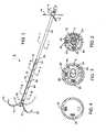
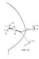
- FIG. 1shows a needle made in accordance with the present invention.
- FIG. 2is a cross-sectional view of the device along line I-I of FIG. 1 .
- FIG. 3is a cross-sectional view of the device along line II-II of FIG. 1 .
- FIG. 4is a cross-sectional view of the device along line III-III of FIG. 1 .
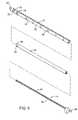
- FIG. 5is an exploded view of the shaft and locking mechanism.
- FIG. 6shows the anchors
- FIG. 7shows the flexible portion of the shaft.
- FIG. 8shows the locking mechanism
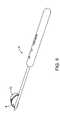
- FIG. 9shows a tissue removing device.
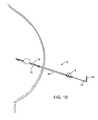
- FIG. 10shows the needle introduced into a breast.
- FIG. 11shows a first anchor deployed within the breast.
- FIG. 12shows a second anchor deployed within the breast.
- FIG. 13shows a stiffener removed to provide a flexible proximal end.
- FIG. 14shows the flexible, proximal portion taped to the breast.
- FIG. 15shows a tissue removing device advanced over the needle and a cutting element deployed.
- FIG. 16shows a void where the tissue removing device has removed the tissue area of interest.
- a needle 2 made in accordance with the present inventionis shown.
- the needle 2may be used to perform or help perform any procedure anywhere in the body.
- the needle 2may be used to mark the location of a tissue area of interest such as a tissue area to be removed.
- the needle 2is used to mark breast tissue which is to be removed ( FIG. 12 ).
- the term “needle” as used hereinshall mean any device having an elongate shaft.
- the device 2may have actuators, manipulators, ablation elements, RF, ultrasound, or other functionality without departing from the scope of the invention.
- the needle 2may be introduced in the breast in a rigid condition to facilitate introduction and then changed to a more flexible condition.
- conventional needlesare often introduced into the patient to mark a tissue area of interest such as a tissue area to be removed.
- the needleis often introduced in one room of the hospital or clinic where the area of interest can be visualized during introduction. After the needle has been introduced, the procedure takes place elsewhere such as in a surgical room.
- a rigid needle protruding from the breastcan present obvious problems with respect to inadvertent contact.
- the present inventionprovides the ability to make part of the needle 2 flexible so that the flexible part of the needle 2 can be moved out of the way or even taped to the patient ( FIGS. 13 and 14 ).
- the needle 2may or may not penetrate the tissue being removed depending upon the particular procedure performed.
- the flexible part of the needle 2may provide other advantages as described below.
- the needle 2may be changed between the rigid and flexible conditions using any suitable structure such as a removable stiffener 4 . After removal of the stiffener 4 , the rigid condition may be restored at a later time by simply replacing the stiffener 4 .
- the needle 2When using the needle 2 to manipulate tissue being cut, it may be advantageous to maintain the flexible condition to apply tension at varying angles depending upon the area being cut. This provides obvious advantages over conventional rigid needles (see dotted-line position of FIG. 13 ).
- One such systempermanently anchors the needle to the tissue with wires fused to the tissue using RF energy. The rigid needle is then manipulated while cutting and removing tissue around the needle and wires.
- the needle 2may also be used to guide another medical device such as a tissue cutting device 6 .
- a tissue cutting device 6Any suitable tissue cutting device may be used and one of particular device interest is disclosed in U.S. Pat. Nos. 6,440,147 and 6,022,362 which are hereby incorporated by reference.
- the tissue cutting device 6has a cutting element 8 movable between collapsed and bowed positions. The tissue cutting device 6 is pivoted or rotated so that the cutting element 8 sweeps through and cuts the tissue along an arc.
- a tissue collection element 10may also be provided which collects the tissue being cut.
- the needle 2may have an indicator 14 to mark an angular position relative to the longitudinal axis 16 of the needle 2 .
- the indicator 14extends radially outward from the needle at a angle selected by the user.
- the indicator 14may also simply be a longitudinal stripe 18 or other marking on the shaft which indicates a particular angular orientation on the needle 2 .
- the indicator 14may provide information to the user regarding various parameters depending upon the procedure being performed. For example, when using the device 6 described above, the angular position, or positions, provide the user with the angular extent of the tissue to be removed.
- the indicators 14may be coupled to one more anchors 20 which are deployed to anchor the needle 2 .
- the anchor 20is preferably curved, such as J- or C-shaped, and extends radially to lie within the same angular orientation as the indicator 14 .
- An advantage of coupling the indicator 14 to the anchor 20is that anchor 20 itself provides information regarding the relative orientation or the needle 2 , anchor 20 and tissue area of interest Thus, the anchor 20 itself may be one of the indicators 14 .
- the anchor 20 and indicator 14are preferably aligned at the same angular orientation, they may also be offset to account for the geometry of other devices used with the needle 2 .
- the indicators 14may also be independent of any anchoring elements.
- the needle 2may be placed in the breast and the indicators 14 could then be moved to selected angular position(s).
- the needle 2may also have depth markers 22 along the body.
- the anchor 20is preferably a stainless steel wire having a sharpened tip to pierce through the tissue. The orientation of the anchor 20 is partially guided by the geometry of the arc-shaped lumens receiving the anchors 20 ( FIGS. 2 and 3 ).
- the needle 2has a shaft 30 having a rigid tube 32 coupled to a flexible tube 34 .
- the rigid tube 32has a sharp tip 37 to pierce tissue.
- the rigid tube 32is preferably a hypotube of stainless steel having a size of 18 GA to 12 GA such as 16 GA.
- the rigid tube 32has two openings 35 , 36 or slots at or near the distal end through which the anchors 20 extend.
- the first opening 35is radially smaller than the second 36 since the anchor 20 is deployed at a predetermined angular orientation aligned with the longitudinal marker or stripe 18 .
- the needle 2may be configured with both anchors 20 rotatable or pivotable within the openings 35 , 36 .
- the tube 32also has a stop 38 which prevents further longitudinal movement of the tissue cutting device 6 and markers 40 for providing depth information.
- the flexible tube 34may be a three-lumen extrusion.
- the first and second lumens 42 , 44each receive one of the anchors 20 and the third lumen 46 receives the stiffener 4 .
- the flexible tube 34is bonded to the rigid tube 32 in any suitable manner such as with an adhesive.
- the flexible tube 34is sized to fit within the rigid tube 32 .
- a portion of the side wall around the stiffener 4is removed to form a cut-out 48 having a shoulder 50 to lock the stiffener 4 as now described
- the stiffener 4is shown.
- An actuator 52which may simply be an elongate rod, is advanced to expand and open first and second prongs 54 , 56 at the distal end of the stiffener 4 .
- the first prong 54has a shoulder 58 which engages the shoulder 50 formed by the cut-out 48 portion of the tube 34 .
- the shoulder 50may, of course, also be formed by the rigid tube 32 or a piece of material attached to inner surface of the rigid tube 32 .
- FIG. 14shows the proximal portion taped to the patient after removing the stiffener 4 .
- FIG. 13also shows the flexible portion being tensioned in different directions.
- the needle 2is introduced into the area of interest under suitable visualization such as ultrasound. Once the needle 2 has been introduced in a desired or known orientation relative to the tissue area of interest, the entire needle 2 is rotated so that the first indicator 14 and marker 18 are aligned with a first angular position relative to the tissue area of interest. The first anchor 20 is then deployed into the tissue with the anchor 20 deployed at the selected angular orientation. The second indicator 14 is then rotated to a second selected angular orientation with respect to the area of interest.
- the second orientationis determined by visualizing the area of interest relative to the needle 2 and/or first anchor 20 to determine the appropriate location for the second anchor 20 .
- the second anchor 20is then deployed by advancing the anchor into the tissue.
- the needle 2 and anchors 20themselves provide visual landmarks for locating the area of interest.
- the markings on the needle 2 and the indicators 14also help to guide use of the tissue cutting device 6 as described herein.
- the stiffener 4is then removed to provide the flexible proximal portion.
- the flexible proximal portionmay be taped to the patient to prevent inadvertent contact as shown in FIG. 14 .
- the flexible conditionmay be maintained to provide the benefit described above such as the ability to pull from varying angles as compared to a conventional rigid needle.
- the tissue removal device 6may then be coupled to the needle 2 as shown in FIG. 15 and then advanced while being guided by the needle 2 .
- the needle 2may be introduced to a predetermined depth where the longitudinal stop 38 guides the depth of introduction of the tissue removal device. Of course, the needle 2 may be introduced deeper into the tissue with the user using the depth markings 40 on the needle 2 and/or tissue removal device 6 to determine the appropriate introduction depth for the tissue removal device 6 .
- the cutting element 8is then deployed to the bowed position and the cutting element 8 is swept through tissue to cut around the tissue area of interest.
- the tissueis then collected by the collection element 10 for removal.
- the device 6is then withdrawn and the anchors 30 are retracted to permit withdrawal of the needle 2 as well.
- the present inventioncan be practiced in many different forms and for many different procedures. Furthermore, the aspects of the invention are distinct. For example, the present invention provides a flexible proximal portion which is distinct from the ability to mark angular orientations. Thus, each feature of the present invention are independent of one another. Finally, numerous physical modifications may be made without departing from the scope of the invention.
- the anchorsmay be spikes, an expandable mesh, prongs, or a helical screw and the cutting device may be a wire cage, a multiple-bladed cutter, or simply a scalpel without departing from numerous aspects of the invention.
Landscapes
- Health & Medical Sciences (AREA)
- Surgery (AREA)
- Life Sciences & Earth Sciences (AREA)
- Heart & Thoracic Surgery (AREA)
- Pathology (AREA)
- Oral & Maxillofacial Surgery (AREA)
- Engineering & Computer Science (AREA)
- Biomedical Technology (AREA)
- Nuclear Medicine, Radiotherapy & Molecular Imaging (AREA)
- Medical Informatics (AREA)
- Molecular Biology (AREA)
- Animal Behavior & Ethology (AREA)
- General Health & Medical Sciences (AREA)
- Public Health (AREA)
- Veterinary Medicine (AREA)
- Surgical Instruments (AREA)
Abstract
Description
Claims (47)
Priority Applications (1)
| Application Number | Priority Date | Filing Date | Title |
|---|---|---|---|
| US11/145,808US7438693B2 (en) | 2002-10-16 | 2005-06-06 | Devices and methods for performing procedures on a breast |
Applications Claiming Priority (2)
| Application Number | Priority Date | Filing Date | Title |
|---|---|---|---|
| US10/272,448US6936014B2 (en) | 2002-10-16 | 2002-10-16 | Devices and methods for performing procedures on a breast |
| US11/145,808US7438693B2 (en) | 2002-10-16 | 2005-06-06 | Devices and methods for performing procedures on a breast |
Related Parent Applications (1)
| Application Number | Title | Priority Date | Filing Date |
|---|---|---|---|
| US10/272,448DivisionUS6936014B2 (en) | 1998-09-03 | 2002-10-16 | Devices and methods for performing procedures on a breast |
Publications (2)
| Publication Number | Publication Date |
|---|---|
| US20050222521A1 US20050222521A1 (en) | 2005-10-06 |
| US7438693B2true US7438693B2 (en) | 2008-10-21 |
Family
ID=32092609
Family Applications (2)
| Application Number | Title | Priority Date | Filing Date |
|---|---|---|---|
| US10/272,448Expired - Fee RelatedUS6936014B2 (en) | 1998-09-03 | 2002-10-16 | Devices and methods for performing procedures on a breast |
| US11/145,808Expired - Fee RelatedUS7438693B2 (en) | 2002-10-16 | 2005-06-06 | Devices and methods for performing procedures on a breast |
Family Applications Before (1)
| Application Number | Title | Priority Date | Filing Date |
|---|---|---|---|
| US10/272,448Expired - Fee RelatedUS6936014B2 (en) | 1998-09-03 | 2002-10-16 | Devices and methods for performing procedures on a breast |
Country Status (6)
| Country | Link |
|---|---|
| US (2) | US6936014B2 (en) |
| EP (1) | EP1553874A4 (en) |
| JP (1) | JP2006502821A (en) |
| AU (1) | AU2003272211B2 (en) |
| CA (1) | CA2502074A1 (en) |
| WO (1) | WO2004039263A1 (en) |
Cited By (2)
| Publication number | Priority date | Publication date | Assignee | Title |
|---|---|---|---|---|
| US20110144533A1 (en)* | 2009-12-15 | 2011-06-16 | Rafal Chudzik | Introducer cannula having a tissue anchor for use with a medical instrument |
| US20150105627A1 (en)* | 2012-06-21 | 2015-04-16 | Olympus Corporation | Access port |
Families Citing this family (66)
| Publication number | Priority date | Publication date | Assignee | Title |
|---|---|---|---|---|
| US8668737B2 (en) | 1997-10-10 | 2014-03-11 | Senorx, Inc. | Tissue marking implant |
| US7637948B2 (en) | 1997-10-10 | 2009-12-29 | Senorx, Inc. | Tissue marking implant |
| US6936014B2 (en)* | 2002-10-16 | 2005-08-30 | Rubicor Medical, Inc. | Devices and methods for performing procedures on a breast |
| US7517348B2 (en)* | 1998-09-03 | 2009-04-14 | Rubicor Medical, Inc. | Devices and methods for performing procedures on a breast |
| US7651505B2 (en) | 2002-06-17 | 2010-01-26 | Senorx, Inc. | Plugged tip delivery for marker placement |
| US6862470B2 (en) | 1999-02-02 | 2005-03-01 | Senorx, Inc. | Cavity-filling biopsy site markers |
| US8498693B2 (en) | 1999-02-02 | 2013-07-30 | Senorx, Inc. | Intracorporeal marker and marker delivery device |
| US9820824B2 (en) | 1999-02-02 | 2017-11-21 | Senorx, Inc. | Deployment of polysaccharide markers for treating a site within a patent |
| US7983734B2 (en) | 2003-05-23 | 2011-07-19 | Senorx, Inc. | Fibrous marker and intracorporeal delivery thereof |
| US20090030309A1 (en) | 2007-07-26 | 2009-01-29 | Senorx, Inc. | Deployment of polysaccharide markers |
| US6725083B1 (en) | 1999-02-02 | 2004-04-20 | Senorx, Inc. | Tissue site markers for in VIVO imaging |
| US8361082B2 (en) | 1999-02-02 | 2013-01-29 | Senorx, Inc. | Marker delivery device with releasable plug |
| US6575991B1 (en) | 1999-06-17 | 2003-06-10 | Inrad, Inc. | Apparatus for the percutaneous marking of a lesion |
| US7041101B2 (en)* | 1999-12-27 | 2006-05-09 | Neothermia Corporation | Electrosurgical accessing of tissue with controlled collateral thermal phenomena |
| CA2659518A1 (en) | 2000-11-20 | 2002-05-30 | Senorx, Inc. | Tissue site markers for in vivo imaging |
| US8123698B2 (en)* | 2002-10-07 | 2012-02-28 | Suros Surgical Systems, Inc. | System and method for minimally invasive disease therapy |
| US20060036158A1 (en) | 2003-11-17 | 2006-02-16 | Inrad, Inc. | Self-contained, self-piercing, side-expelling marking apparatus |
| WO2004045480A2 (en) | 2002-11-18 | 2004-06-03 | Inrad, Inc. | Apparatus for implanting a preloaded localization wire |
| US7311673B2 (en)* | 2003-04-24 | 2007-12-25 | Acueity, Inc. | Biopsy device |
| US7877133B2 (en) | 2003-05-23 | 2011-01-25 | Senorx, Inc. | Marker or filler forming fluid |
| US7494473B2 (en)* | 2003-07-30 | 2009-02-24 | Intact Medical Corp. | Electrical apparatus and system with improved tissue capture component |
| US20050273002A1 (en) | 2004-06-04 | 2005-12-08 | Goosen Ryan L | Multi-mode imaging marker |
| US7670282B2 (en) | 2004-06-14 | 2010-03-02 | Pneumrx, Inc. | Lung access device |
| EP3542736A1 (en) | 2004-06-16 | 2019-09-25 | PneumRx, Inc. | Intra-bronchial lung volume reduction system |
| CA2570261C (en) | 2004-07-08 | 2014-06-10 | Pneumrx, Inc. | Pleural effusion treatment device, method and material |
| US7766891B2 (en) | 2004-07-08 | 2010-08-03 | Pneumrx, Inc. | Lung device with sealing features |
| US8409111B2 (en)* | 2004-11-22 | 2013-04-02 | Bard Peripheral Vascular, Inc. | Removable localizing wire |
| US8419656B2 (en)* | 2004-11-22 | 2013-04-16 | Bard Peripheral Vascular, Inc. | Post decompression marker introducer system |
| WO2006058195A2 (en) | 2004-11-23 | 2006-06-01 | Pneumrx, Inc. | Steerable device for accessing a target site and methods |
| US10357328B2 (en) | 2005-04-20 | 2019-07-23 | Bard Peripheral Vascular, Inc. and Bard Shannon Limited | Marking device with retractable cannula |
| US8052658B2 (en) | 2005-10-07 | 2011-11-08 | Bard Peripheral Vascular, Inc. | Drug-eluting tissue marker |
| DE602006016319D1 (en)* | 2005-11-16 | 2010-09-30 | Cook Inc | MARKER FOR MARKING A AREA IN A BODY TISSUE |
| US8157837B2 (en) | 2006-03-13 | 2012-04-17 | Pneumrx, Inc. | Minimally invasive lung volume reduction device and method |
| US8888800B2 (en) | 2006-03-13 | 2014-11-18 | Pneumrx, Inc. | Lung volume reduction devices, methods, and systems |
| US9402633B2 (en) | 2006-03-13 | 2016-08-02 | Pneumrx, Inc. | Torque alleviating intra-airway lung volume reduction compressive implant structures |
| USD578216S1 (en) | 2006-06-12 | 2008-10-07 | Angiomed Gmby & Co. Medizintechnik Kg | Handle for a medical delivery device |
| USD598543S1 (en) | 2006-06-13 | 2009-08-18 | Angiomed Gmbh & Co. Medizintechnik Kg | Handle for a medical delivery device |
| WO2008051749A2 (en) | 2006-10-23 | 2008-05-02 | C. R. Bard, Inc. | Breast marker |
| US9579077B2 (en) | 2006-12-12 | 2017-02-28 | C.R. Bard, Inc. | Multiple imaging mode tissue marker |
| WO2008076973A2 (en) | 2006-12-18 | 2008-06-26 | C.R.Bard Inc. | Biopsy marker with in situ-generated imaging properties |
| US8128592B2 (en) | 2007-07-11 | 2012-03-06 | Apollo Endosurgery, Inc. | Methods and systems for performing submucosal medical procedures |
| US8317771B2 (en)* | 2007-07-11 | 2012-11-27 | Apollo Endosurgery, Inc. | Methods and systems for performing submucosal medical procedures |
| US8066689B2 (en) | 2007-07-11 | 2011-11-29 | Apollo Endosurgery, Inc. | Methods and systems for submucosal implantation of a device for diagnosis and treatment with a therapeutic agent |
| US8929988B2 (en) | 2007-07-11 | 2015-01-06 | Apollo Endosurgery, Inc. | Methods and systems for submucosal implantation of a device for diagnosis and treatment of a body |
| US7824377B2 (en)* | 2007-12-21 | 2010-11-02 | St. Jude Medical, Atrial Fibrillation Division, Inc. | Tissue anchoring catheter systems and methods |
| WO2009099767A2 (en) | 2008-01-31 | 2009-08-13 | C.R. Bard, Inc. | Biopsy tissue marker |
| EP3785756B1 (en)* | 2008-02-05 | 2025-03-26 | Boston Scientific Scimed, Inc. | Crossing occlusions in blood vessels |
| US20090287045A1 (en) | 2008-05-15 | 2009-11-19 | Vladimir Mitelberg | Access Systems and Methods of Intra-Abdominal Surgery |
| US9173669B2 (en) | 2008-09-12 | 2015-11-03 | Pneumrx, Inc. | Enhanced efficacy lung volume reduction devices, methods, and systems |
| US9327061B2 (en) | 2008-09-23 | 2016-05-03 | Senorx, Inc. | Porous bioabsorbable implant |
| US9186128B2 (en) | 2008-10-01 | 2015-11-17 | Covidien Lp | Needle biopsy device |
| US9332973B2 (en) | 2008-10-01 | 2016-05-10 | Covidien Lp | Needle biopsy device with exchangeable needle and integrated needle protection |
| US11298113B2 (en) | 2008-10-01 | 2022-04-12 | Covidien Lp | Device for needle biopsy with integrated needle protection |
| US8968210B2 (en) | 2008-10-01 | 2015-03-03 | Covidien LLP | Device for needle biopsy with integrated needle protection |
| US9782565B2 (en) | 2008-10-01 | 2017-10-10 | Covidien Lp | Endoscopic ultrasound-guided biliary access system |
| EP4215147A3 (en) | 2008-12-30 | 2023-10-18 | C. R. Bard, Inc. | Marker delivery device for tissue marker placement |
| GB2469062B (en) | 2009-03-31 | 2011-06-15 | Igal Gigi | Tissue sampling device and method |
| WO2010135352A1 (en) | 2009-05-18 | 2010-11-25 | Pneumrx, Inc. | Cross-sectional modification during deployment of an elongate lung volume reduction device |
| EP2852327A4 (en) | 2012-05-10 | 2016-03-16 | Arch Medical Devices Ltd | Biopsy needle with a laterally expandable distal portion |
| USD715942S1 (en) | 2013-09-24 | 2014-10-21 | C. R. Bard, Inc. | Tissue marker for intracorporeal site identification |
| USD716451S1 (en) | 2013-09-24 | 2014-10-28 | C. R. Bard, Inc. | Tissue marker for intracorporeal site identification |
| USD715442S1 (en) | 2013-09-24 | 2014-10-14 | C. R. Bard, Inc. | Tissue marker for intracorporeal site identification |
| USD716450S1 (en) | 2013-09-24 | 2014-10-28 | C. R. Bard, Inc. | Tissue marker for intracorporeal site identification |
| US10390838B1 (en) | 2014-08-20 | 2019-08-27 | Pneumrx, Inc. | Tuned strength chronic obstructive pulmonary disease treatment |
| WO2019203820A1 (en) | 2018-04-18 | 2019-10-24 | C.R. Bard, Inc. | Dual lumen coaxial introducer having integrated tissue marker delivery |
| LU501863B1 (en) | 2022-04-19 | 2023-10-19 | Alexandre Cheretakis | Flexible graduated hook-wire and kit for positionning thereof in a patient's breast, axilla or other soft tissue |
Citations (99)
| Publication number | Priority date | Publication date | Assignee | Title |
|---|---|---|---|---|
| US1813902A (en) | 1928-01-18 | 1931-07-14 | Liebel Flarsheim Co | Electrosurgical apparatus |
| US2816552A (en) | 1954-06-29 | 1957-12-17 | Roy D Hoffman | Teat bistoury with improved cutter blade adjusting means |
| US3320957A (en) | 1964-05-21 | 1967-05-23 | Sokolik Edward | Surgical instrument |
| US3732858A (en) | 1968-09-16 | 1973-05-15 | Surgical Design Corp | Apparatus for removing blood clots, cataracts and other objects from the eye |
| US3749085A (en) | 1970-06-26 | 1973-07-31 | J Willson | Vascular tissue removing device |
| GB1331468A (en) | 1969-10-03 | 1973-09-26 | Bosch Gmbh Robert | Connection connecting electrical conductors |
| US3910279A (en) | 1973-06-20 | 1975-10-07 | Olympus Optical Co | Electrosurgical instrument |
| FR2275226A1 (en) | 1974-05-30 | 1976-01-16 | Wolf Gmbh Richard | CATHETER INCLUDING A LOOP THAT CAN BE ELECTRICALLY POWERED |
| US3955578A (en) | 1974-12-23 | 1976-05-11 | Cook Inc. | Rotatable surgical snare |
| US4099518A (en) | 1976-05-10 | 1978-07-11 | Baylis Shelby M | Biopsy apparatus |
| US4245653A (en) | 1979-01-02 | 1981-01-20 | Kenneth Weaver | Method and apparatus for obtaining specimens of endometrial tissue |
| US4347846A (en) | 1979-12-07 | 1982-09-07 | Porges | Surgical extractor |
| SU1235497A1 (en) | 1984-04-11 | 1986-06-07 | Ташкентский Ордена Трудового Красного Знамени Государственный Медицинский Институт | Arrangement for dissection of stenosis of tubular organs |
| US4611594A (en) | 1984-04-11 | 1986-09-16 | Northwestern University | Medical instrument for containment and removal of calculi |
| US4650466A (en) | 1985-11-01 | 1987-03-17 | Angiobrade Partners | Angioplasty device |
| SU1355266A1 (en) | 1985-12-05 | 1987-11-30 | 3. Янгибаев | Arrangement for dissection of constrictions of tubular organs |
| GB2204496A (en) | 1987-05-15 | 1988-11-16 | Syntex Inc | Device for collecting biological material |
| US4890611A (en) | 1988-04-05 | 1990-01-02 | Thomas J. Fogarty | Endarterectomy apparatus and method |
| US4903696A (en) | 1988-10-06 | 1990-02-27 | Everest Medical Corporation | Electrosurgical generator |
| US4966604A (en) | 1989-01-23 | 1990-10-30 | Interventional Technologies Inc. | Expandable atherectomy cutter with flexibly bowed blades |
| US5071424A (en) | 1989-08-18 | 1991-12-10 | Evi Corporation | Catheter atherotome |
| US5083570A (en) | 1990-06-18 | 1992-01-28 | Mosby Richard A | Volumetric localization/biopsy/surgical device |
| US5100423A (en) | 1990-08-21 | 1992-03-31 | Medical Engineering & Development Institute, Inc. | Ablation catheter |
| US5147355A (en) | 1988-09-23 | 1992-09-15 | Brigham And Womens Hospital | Cryoablation catheter and method of performing cryoablation |
| US5152293A (en) | 1991-07-01 | 1992-10-06 | Northwestern University | Finger-mounted intraoperative imaging device |
| US5156610A (en) | 1989-08-18 | 1992-10-20 | Evi Corporation | Catheter atherotome |
| WO1992020291A1 (en) | 1991-05-24 | 1992-11-26 | Applied Medical Resources, Inc. | Articulating tissue cutter assembly |
| US5174296A (en) | 1990-03-29 | 1992-12-29 | Fujitsu Limited | Ultrasonic probe having a piezoelectrical element |
| US5176688A (en) | 1991-07-17 | 1993-01-05 | Perinchery Narayan | Stone extractor and method |
| US5192291A (en) | 1992-01-13 | 1993-03-09 | Interventional Technologies, Inc. | Rotationally expandable atherectomy cutter assembly |
| US5211651A (en) | 1989-08-18 | 1993-05-18 | Evi Corporation | Catheter atherotome |
| US5217479A (en) | 1991-02-14 | 1993-06-08 | Linvatec Corporation | Surgical cutting instrument |
| US5224945A (en) | 1992-01-13 | 1993-07-06 | Interventional Technologies, Inc. | Compressible/expandable atherectomy cutter |
| US5224488A (en) | 1992-08-31 | 1993-07-06 | Neuffer Francis H | Biopsy needle with extendable cutting means |
| US5282484A (en) | 1989-08-18 | 1994-02-01 | Endovascular Instruments, Inc. | Method for performing a partial atherectomy |
| US5308321A (en) | 1992-05-05 | 1994-05-03 | Castro Donna J | Retainer assisted by vacuum expansion system |
| US5318576A (en) | 1992-12-16 | 1994-06-07 | Plassche Jr Walter M | Endovascular surgery systems |
| US5325860A (en) | 1991-11-08 | 1994-07-05 | Mayo Foundation For Medical Education And Research | Ultrasonic and interventional catheter and method |
| WO1995002370A2 (en) | 1993-07-15 | 1995-01-26 | Aws Shakir Mustafa Salim | Tunnelling catheter |
| WO1995002371A2 (en) | 1993-07-15 | 1995-01-26 | Aws Shakir Mustafa Salim | Rectal and rectosigmoid cancer tunnelling umbrella |
| US5415656A (en) | 1993-09-28 | 1995-05-16 | American Medical Systems, Inc. | Electrosurgical apparatus |
| US5441510A (en) | 1993-09-01 | 1995-08-15 | Technology Development Center | Bi-axial cutter apparatus for catheter |
| US5527326A (en) | 1992-12-29 | 1996-06-18 | Thomas J. Fogarty | Vessel deposit shearing apparatus |
| US5554163A (en) | 1995-04-27 | 1996-09-10 | Shturman Cardiology Systems, Inc. | Atherectomy device |
| WO1996029946A1 (en) | 1995-03-24 | 1996-10-03 | Board Of Regents Of The University Of Nebraska | Apparatus for ablation of tissue masses |
| DE19528440A1 (en) | 1995-08-02 | 1997-02-06 | Harald Dr Med Kuebler | Surgical cutting instrument for tissue removal - has cutting device enclosed by tubular end section of instrument during insertion and curved transverse to its axial direction in working position |
| US5630426A (en) | 1995-03-03 | 1997-05-20 | Neovision Corporation | Apparatus and method for characterization and treatment of tumors |
| US5632754A (en) | 1994-12-23 | 1997-05-27 | Devices For Vascular Intervention | Universal catheter with interchangeable work element |
| US5672172A (en) | 1994-06-23 | 1997-09-30 | Vros Corporation | Surgical instrument with ultrasound pulse generator |
| GB2311468A (en) | 1996-03-27 | 1997-10-01 | Valleylab Inc | Electrosurgical interstitial resector |
| US5709697A (en) | 1995-11-22 | 1998-01-20 | United States Surgical Corporation | Apparatus and method for removing tissue |
| WO1998008441A1 (en) | 1996-08-29 | 1998-03-05 | Ethicon Endo-Surgery | Methods and devices for collection of soft tissue |
| EP0829232A2 (en) | 1996-08-29 | 1998-03-18 | City Of Hope | Minimally invasive biopsy device |
| NL1004723C2 (en) | 1996-12-06 | 1998-06-09 | Ronald Willem De Haan | Diathermic loop provided with electrically conductive cutting wire |
| US5766191A (en) | 1992-04-07 | 1998-06-16 | Johns Hopkins University | Percutaneous mechanical fragmentation catheter system |
| US5795308A (en)* | 1995-03-09 | 1998-08-18 | Russin; Lincoln D. | Apparatus for coaxial breast biopsy |
| US5794626A (en) | 1994-08-18 | 1998-08-18 | Kieturakis; Maciej J. | Excisional stereotactic apparatus |
| WO1999001074A1 (en) | 1997-07-03 | 1999-01-14 | Neothermia Corporation | Methods and apparatus for therapeutic cauterization of predetermined volumes of biological tissue |
| WO1999004704A2 (en) | 1997-07-24 | 1999-02-04 | Mcguckin James F Jr | Breast surgery method and apparatus |
| US5895399A (en) | 1996-07-17 | 1999-04-20 | Embol-X Inc. | Atherectomy device having trapping and excising means for removal of plaque from the aorta and other arteries |
| US5913855A (en) | 1995-08-15 | 1999-06-22 | Rita Medical Systems, Inc. | Multiple antenna ablation apparatus and method |
| US5928164A (en) | 1994-03-24 | 1999-07-27 | Ethicon Endo-Surgery, Inc. | Apparatus for automated biopsy and collection of soft tissue |
| WO1999043262A1 (en) | 1998-02-27 | 1999-09-02 | Conway-Stuart Medical, Inc. | Method to electrosurgically treat esophageal sphincters |
| US5947964A (en) | 1995-03-03 | 1999-09-07 | Neothermia Corporation | Methods and apparatus for therapeutic cauterization of predetermined volumes of biological tissue |
| WO1999044506A1 (en) | 1998-03-03 | 1999-09-10 | Senorx, Inc. | Breast biopsy system and method |
| US5954670A (en) | 1994-10-05 | 1999-09-21 | Baker; Gary H. | Mandrel-guided tandem multiple channel biopsy guide device and method of use |
| US5954655A (en) | 1995-04-17 | 1999-09-21 | Hussman; Karl L. | Method for localizing a lesion using an optical fiber |
| WO1999053851A1 (en) | 1998-04-17 | 1999-10-28 | Wilk And Nakao Medical Technology, Incorporated | Surgical retrieval assembly and associated method |
| US6015390A (en) | 1998-06-12 | 2000-01-18 | D. Krag Llc | System and method for stabilizing and removing tissue |
| US6022362A (en) | 1998-09-03 | 2000-02-08 | Rubicor Medical, Inc. | Excisional biopsy devices and methods |
| WO2000010471A1 (en) | 1998-08-19 | 2000-03-02 | Artemis Medical, Inc. | Target tissue localization device and method |
| WO2000012009A2 (en) | 1998-09-01 | 2000-03-09 | Senorx, Inc. | Securing surgical instruments at target tissue sites |
| US6036708A (en) | 1998-08-13 | 2000-03-14 | Advanced Cardiovascular Systems, Inc. | Cutting stent with flexible tissue extractor |
| WO2000016697A2 (en) | 1998-09-23 | 2000-03-30 | Senorx, Inc. | Electrosurgical biopsy device and method |
| US6063082A (en) | 1997-11-04 | 2000-05-16 | Scimed Life Systems, Inc. | Percutaneous myocardial revascularization basket delivery system and radiofrequency therapeutic device |
| WO2000030531A1 (en) | 1998-11-20 | 2000-06-02 | Senorx Inc. | Tissue acquisition system and method of use |
| WO2000033743A1 (en) | 1998-12-09 | 2000-06-15 | Senorx, Inc. | Tissue specimen encapsulation device and method thereof |
| US6080149A (en) | 1998-01-09 | 2000-06-27 | Radiotherapeutics, Corporation | Method and apparatus for monitoring solid tissue heating |
| US6080151A (en) | 1997-07-21 | 2000-06-27 | Daig Corporation | Ablation catheter |
| US6096053A (en) | 1996-05-03 | 2000-08-01 | Scimed Life Systems, Inc. | Medical retrieval basket |
| WO2000044295A1 (en) | 1999-01-27 | 2000-08-03 | Senorx, Inc. | Tissue specimen isolating and damaging device and method |
| US6099534A (en) | 1997-10-01 | 2000-08-08 | Scimed Life Systems, Inc. | Releasable basket |
| WO2000074561A1 (en) | 1999-06-04 | 2000-12-14 | Artemis Medical, Inc. | Tissue removal methods and apparatus |
| US6221006B1 (en) | 1998-02-10 | 2001-04-24 | Artemis Medical Inc. | Entrapping apparatus and method for use |
| WO2000045854A3 (en) | 1999-02-02 | 2001-04-26 | Senorx Inc | Preparations for time-limited marking of biopsy sites |
| WO2001028445A1 (en) | 1999-10-15 | 2001-04-26 | Neothermia Corporation | Cutting tissue with electrosurgically deployed electrodes |
| WO2001028446A1 (en) | 1999-10-15 | 2001-04-26 | Neothermia Corporation | Cauterization of tissue with deployable electrodes |
| US6238389B1 (en) | 1997-09-30 | 2001-05-29 | Boston Scientific Corporation | Deflectable interstitial ablation device |
| US20010047169A1 (en) | 1997-07-24 | 2001-11-29 | Mcguckin James F. | Surgical biopsy device |
| US6325797B1 (en) | 1999-04-05 | 2001-12-04 | Medtronic, Inc. | Ablation catheter and method for isolating a pulmonary vein |
| US6383145B1 (en) | 1997-09-12 | 2002-05-07 | Imagyn Medical Technologies California, Inc. | Incisional breast biopsy device |
| US6405733B1 (en) | 2000-02-18 | 2002-06-18 | Thomas J. Fogarty | Device for accurately marking tissue |
| US6540695B1 (en)* | 1998-04-08 | 2003-04-01 | Senorx, Inc. | Biopsy anchor device with cutter |
| US6602204B2 (en) | 1998-02-10 | 2003-08-05 | Artemis Medical, Inc | Intraoperative tissue treatment methods |
| US6605047B2 (en) | 2001-09-10 | 2003-08-12 | Vivant Medical, Inc. | Biopsy marker delivery system |
| EP0908156B1 (en) | 1994-08-12 | 2003-11-12 | Rita Medical Systems, Inc. | Multiple electrode ablation apparatus |
| US6679851B2 (en)* | 1998-09-01 | 2004-01-20 | Senorx, Inc. | Tissue accessing and anchoring device and method |
| US6936014B2 (en)* | 2002-10-16 | 2005-08-30 | Rubicor Medical, Inc. | Devices and methods for performing procedures on a breast |
| US20070203428A1 (en)* | 1998-09-03 | 2007-08-30 | Rubicor Medical, Inc. | Devices and methods for performing procedures on a breast |
Family Cites Families (4)
| Publication number | Priority date | Publication date | Assignee | Title |
|---|---|---|---|---|
| US4799495A (en)* | 1987-03-20 | 1989-01-24 | National Standard Company | Localization needle assembly |
| EP0395997A1 (en)* | 1989-05-05 | 1990-11-07 | Becton, Dickinson and Company | Electrically insulated breast lesion localization device |
| US5127916A (en)* | 1991-01-22 | 1992-07-07 | Medical Device Technologies, Inc. | Localization needle assembly |
| US6175760B1 (en)* | 1998-02-17 | 2001-01-16 | University Of Iowa Research Foundation | Lesion localizer for nuclear medicine |
- 2002
- 2002-10-16USUS10/272,448patent/US6936014B2/ennot_activeExpired - Fee Related
- 2003
- 2003-08-06AUAU2003272211Apatent/AU2003272211B2/ennot_activeExpired - Fee Related
- 2003-08-06CACA002502074Apatent/CA2502074A1/ennot_activeAbandoned
- 2003-08-06EPEP03754384Apatent/EP1553874A4/ennot_activeWithdrawn
- 2003-08-06JPJP2004548293Apatent/JP2006502821A/enactivePending
- 2003-08-06WOPCT/US2003/024490patent/WO2004039263A1/enactiveApplication Filing
- 2005
- 2005-06-06USUS11/145,808patent/US7438693B2/ennot_activeExpired - Fee Related
Patent Citations (110)
| Publication number | Priority date | Publication date | Assignee | Title |
|---|---|---|---|---|
| US1813902A (en) | 1928-01-18 | 1931-07-14 | Liebel Flarsheim Co | Electrosurgical apparatus |
| US2816552A (en) | 1954-06-29 | 1957-12-17 | Roy D Hoffman | Teat bistoury with improved cutter blade adjusting means |
| US3320957A (en) | 1964-05-21 | 1967-05-23 | Sokolik Edward | Surgical instrument |
| US3732858A (en) | 1968-09-16 | 1973-05-15 | Surgical Design Corp | Apparatus for removing blood clots, cataracts and other objects from the eye |
| GB1331468A (en) | 1969-10-03 | 1973-09-26 | Bosch Gmbh Robert | Connection connecting electrical conductors |
| US3749085A (en) | 1970-06-26 | 1973-07-31 | J Willson | Vascular tissue removing device |
| US3910279A (en) | 1973-06-20 | 1975-10-07 | Olympus Optical Co | Electrosurgical instrument |
| FR2275226A1 (en) | 1974-05-30 | 1976-01-16 | Wolf Gmbh Richard | CATHETER INCLUDING A LOOP THAT CAN BE ELECTRICALLY POWERED |
| US3955578A (en) | 1974-12-23 | 1976-05-11 | Cook Inc. | Rotatable surgical snare |
| US4099518A (en) | 1976-05-10 | 1978-07-11 | Baylis Shelby M | Biopsy apparatus |
| US4245653A (en) | 1979-01-02 | 1981-01-20 | Kenneth Weaver | Method and apparatus for obtaining specimens of endometrial tissue |
| US4347846A (en) | 1979-12-07 | 1982-09-07 | Porges | Surgical extractor |
| SU1235497A1 (en) | 1984-04-11 | 1986-06-07 | Ташкентский Ордена Трудового Красного Знамени Государственный Медицинский Институт | Arrangement for dissection of stenosis of tubular organs |
| US4611594A (en) | 1984-04-11 | 1986-09-16 | Northwestern University | Medical instrument for containment and removal of calculi |
| US4650466A (en) | 1985-11-01 | 1987-03-17 | Angiobrade Partners | Angioplasty device |
| SU1355266A1 (en) | 1985-12-05 | 1987-11-30 | 3. Янгибаев | Arrangement for dissection of constrictions of tubular organs |
| GB2204496A (en) | 1987-05-15 | 1988-11-16 | Syntex Inc | Device for collecting biological material |
| US4890611A (en) | 1988-04-05 | 1990-01-02 | Thomas J. Fogarty | Endarterectomy apparatus and method |
| US5147355A (en) | 1988-09-23 | 1992-09-15 | Brigham And Womens Hospital | Cryoablation catheter and method of performing cryoablation |
| US4903696A (en) | 1988-10-06 | 1990-02-27 | Everest Medical Corporation | Electrosurgical generator |
| US4966604A (en) | 1989-01-23 | 1990-10-30 | Interventional Technologies Inc. | Expandable atherectomy cutter with flexibly bowed blades |
| US5282484A (en) | 1989-08-18 | 1994-02-01 | Endovascular Instruments, Inc. | Method for performing a partial atherectomy |
| US5156610A (en) | 1989-08-18 | 1992-10-20 | Evi Corporation | Catheter atherotome |
| US5071424A (en) | 1989-08-18 | 1991-12-10 | Evi Corporation | Catheter atherotome |
| US5211651A (en) | 1989-08-18 | 1993-05-18 | Evi Corporation | Catheter atherotome |
| US5174296A (en) | 1990-03-29 | 1992-12-29 | Fujitsu Limited | Ultrasonic probe having a piezoelectrical element |
| US5083570A (en) | 1990-06-18 | 1992-01-28 | Mosby Richard A | Volumetric localization/biopsy/surgical device |
| US5100423A (en) | 1990-08-21 | 1992-03-31 | Medical Engineering & Development Institute, Inc. | Ablation catheter |
| EP0472368B1 (en) | 1990-08-21 | 1995-06-28 | Med Institute, Inc. | Ablation catheter |
| US5217479A (en) | 1991-02-14 | 1993-06-08 | Linvatec Corporation | Surgical cutting instrument |
| WO1992020291A1 (en) | 1991-05-24 | 1992-11-26 | Applied Medical Resources, Inc. | Articulating tissue cutter assembly |
| US5152293A (en) | 1991-07-01 | 1992-10-06 | Northwestern University | Finger-mounted intraoperative imaging device |
| US5176688A (en) | 1991-07-17 | 1993-01-05 | Perinchery Narayan | Stone extractor and method |
| US5325860A (en) | 1991-11-08 | 1994-07-05 | Mayo Foundation For Medical Education And Research | Ultrasonic and interventional catheter and method |
| US5224945A (en) | 1992-01-13 | 1993-07-06 | Interventional Technologies, Inc. | Compressible/expandable atherectomy cutter |
| US5192291A (en) | 1992-01-13 | 1993-03-09 | Interventional Technologies, Inc. | Rotationally expandable atherectomy cutter assembly |
| US5766191A (en) | 1992-04-07 | 1998-06-16 | Johns Hopkins University | Percutaneous mechanical fragmentation catheter system |
| US5308321A (en) | 1992-05-05 | 1994-05-03 | Castro Donna J | Retainer assisted by vacuum expansion system |
| US5224488A (en) | 1992-08-31 | 1993-07-06 | Neuffer Francis H | Biopsy needle with extendable cutting means |
| US5318576A (en) | 1992-12-16 | 1994-06-07 | Plassche Jr Walter M | Endovascular surgery systems |
| US5527326A (en) | 1992-12-29 | 1996-06-18 | Thomas J. Fogarty | Vessel deposit shearing apparatus |
| WO1995002370A2 (en) | 1993-07-15 | 1995-01-26 | Aws Shakir Mustafa Salim | Tunnelling catheter |
| WO1995002371A2 (en) | 1993-07-15 | 1995-01-26 | Aws Shakir Mustafa Salim | Rectal and rectosigmoid cancer tunnelling umbrella |
| US5441510A (en) | 1993-09-01 | 1995-08-15 | Technology Development Center | Bi-axial cutter apparatus for catheter |
| US5415656A (en) | 1993-09-28 | 1995-05-16 | American Medical Systems, Inc. | Electrosurgical apparatus |
| US5928164A (en) | 1994-03-24 | 1999-07-27 | Ethicon Endo-Surgery, Inc. | Apparatus for automated biopsy and collection of soft tissue |
| US5672172A (en) | 1994-06-23 | 1997-09-30 | Vros Corporation | Surgical instrument with ultrasound pulse generator |
| EP0908156B1 (en) | 1994-08-12 | 2003-11-12 | Rita Medical Systems, Inc. | Multiple electrode ablation apparatus |
| US5794626A (en) | 1994-08-18 | 1998-08-18 | Kieturakis; Maciej J. | Excisional stereotactic apparatus |
| US6387056B1 (en) | 1994-08-18 | 2002-05-14 | Maciej J. Kieturakis | Excisional biopsy needle and method for use with image-directed technology |
| US5954670A (en) | 1994-10-05 | 1999-09-21 | Baker; Gary H. | Mandrel-guided tandem multiple channel biopsy guide device and method of use |
| US5632754A (en) | 1994-12-23 | 1997-05-27 | Devices For Vascular Intervention | Universal catheter with interchangeable work element |
| US5928159A (en) | 1995-03-03 | 1999-07-27 | Neothermia Corporation | Apparatus and method for characterization and treatment of tumors |
| US5947964A (en) | 1995-03-03 | 1999-09-07 | Neothermia Corporation | Methods and apparatus for therapeutic cauterization of predetermined volumes of biological tissue |
| US5630426A (en) | 1995-03-03 | 1997-05-20 | Neovision Corporation | Apparatus and method for characterization and treatment of tumors |
| US6106524A (en) | 1995-03-03 | 2000-08-22 | Neothermia Corporation | Methods and apparatus for therapeutic cauterization of predetermined volumes of biological tissue |
| US5795308A (en)* | 1995-03-09 | 1998-08-18 | Russin; Lincoln D. | Apparatus for coaxial breast biopsy |
| WO1996029946A1 (en) | 1995-03-24 | 1996-10-03 | Board Of Regents Of The University Of Nebraska | Apparatus for ablation of tissue masses |
| US5954655A (en) | 1995-04-17 | 1999-09-21 | Hussman; Karl L. | Method for localizing a lesion using an optical fiber |
| US5554163A (en) | 1995-04-27 | 1996-09-10 | Shturman Cardiology Systems, Inc. | Atherectomy device |
| DE19528440A1 (en) | 1995-08-02 | 1997-02-06 | Harald Dr Med Kuebler | Surgical cutting instrument for tissue removal - has cutting device enclosed by tubular end section of instrument during insertion and curved transverse to its axial direction in working position |
| US5913855A (en) | 1995-08-15 | 1999-06-22 | Rita Medical Systems, Inc. | Multiple antenna ablation apparatus and method |
| US5709697A (en) | 1995-11-22 | 1998-01-20 | United States Surgical Corporation | Apparatus and method for removing tissue |
| DE19706751A1 (en) | 1996-03-27 | 1997-10-02 | Valleylab Inc | Electrosurgical device for removing tissue in body areas |
| GB2311468A (en) | 1996-03-27 | 1997-10-01 | Valleylab Inc | Electrosurgical interstitial resector |
| US6096053A (en) | 1996-05-03 | 2000-08-01 | Scimed Life Systems, Inc. | Medical retrieval basket |
| US5895399A (en) | 1996-07-17 | 1999-04-20 | Embol-X Inc. | Atherectomy device having trapping and excising means for removal of plaque from the aorta and other arteries |
| EP0829232A2 (en) | 1996-08-29 | 1998-03-18 | City Of Hope | Minimally invasive biopsy device |
| WO1998008441A1 (en) | 1996-08-29 | 1998-03-05 | Ethicon Endo-Surgery | Methods and devices for collection of soft tissue |
| EP0829232A3 (en) | 1996-08-29 | 1998-03-25 | City Of Hope | Minimally invasive biopsy device |
| NL1004723C2 (en) | 1996-12-06 | 1998-06-09 | Ronald Willem De Haan | Diathermic loop provided with electrically conductive cutting wire |
| WO1999001074A1 (en) | 1997-07-03 | 1999-01-14 | Neothermia Corporation | Methods and apparatus for therapeutic cauterization of predetermined volumes of biological tissue |
| US6080151A (en) | 1997-07-21 | 2000-06-27 | Daig Corporation | Ablation catheter |
| WO1999004704A2 (en) | 1997-07-24 | 1999-02-04 | Mcguckin James F Jr | Breast surgery method and apparatus |
| US20010047169A1 (en) | 1997-07-24 | 2001-11-29 | Mcguckin James F. | Surgical biopsy device |
| US6280450B1 (en) | 1997-07-24 | 2001-08-28 | Rex Medical, Lp | Breast surgery method and apparatus |
| US6383145B1 (en) | 1997-09-12 | 2002-05-07 | Imagyn Medical Technologies California, Inc. | Incisional breast biopsy device |
| US6238389B1 (en) | 1997-09-30 | 2001-05-29 | Boston Scientific Corporation | Deflectable interstitial ablation device |
| US6099534A (en) | 1997-10-01 | 2000-08-08 | Scimed Life Systems, Inc. | Releasable basket |
| US6063082A (en) | 1997-11-04 | 2000-05-16 | Scimed Life Systems, Inc. | Percutaneous myocardial revascularization basket delivery system and radiofrequency therapeutic device |
| US6080149A (en) | 1998-01-09 | 2000-06-27 | Radiotherapeutics, Corporation | Method and apparatus for monitoring solid tissue heating |
| US6602204B2 (en) | 1998-02-10 | 2003-08-05 | Artemis Medical, Inc | Intraoperative tissue treatment methods |
| US6221006B1 (en) | 1998-02-10 | 2001-04-24 | Artemis Medical Inc. | Entrapping apparatus and method for use |
| WO1999043262A1 (en) | 1998-02-27 | 1999-09-02 | Conway-Stuart Medical, Inc. | Method to electrosurgically treat esophageal sphincters |
| WO1999044506A1 (en) | 1998-03-03 | 1999-09-10 | Senorx, Inc. | Breast biopsy system and method |
| US6331166B1 (en) | 1998-03-03 | 2001-12-18 | Senorx, Inc. | Breast biopsy system and method |
| US6540695B1 (en)* | 1998-04-08 | 2003-04-01 | Senorx, Inc. | Biopsy anchor device with cutter |
| US20020058885A1 (en) | 1998-04-08 | 2002-05-16 | Burbank Fred H. | Tissue specimen encapsulation device and method thereof |
| WO1999053851A1 (en) | 1998-04-17 | 1999-10-28 | Wilk And Nakao Medical Technology, Incorporated | Surgical retrieval assembly and associated method |
| US6015390A (en) | 1998-06-12 | 2000-01-18 | D. Krag Llc | System and method for stabilizing and removing tissue |
| US6036708A (en) | 1998-08-13 | 2000-03-14 | Advanced Cardiovascular Systems, Inc. | Cutting stent with flexible tissue extractor |
| US6179860B1 (en) | 1998-08-19 | 2001-01-30 | Artemis Medical, Inc. | Target tissue localization device and method |
| WO2000010471A1 (en) | 1998-08-19 | 2000-03-02 | Artemis Medical, Inc. | Target tissue localization device and method |
| US6679851B2 (en)* | 1998-09-01 | 2004-01-20 | Senorx, Inc. | Tissue accessing and anchoring device and method |
| WO2000012009A2 (en) | 1998-09-01 | 2000-03-09 | Senorx, Inc. | Securing surgical instruments at target tissue sites |
| US6022362A (en) | 1998-09-03 | 2000-02-08 | Rubicor Medical, Inc. | Excisional biopsy devices and methods |
| US20070203428A1 (en)* | 1998-09-03 | 2007-08-30 | Rubicor Medical, Inc. | Devices and methods for performing procedures on a breast |
| WO2000016697A2 (en) | 1998-09-23 | 2000-03-30 | Senorx, Inc. | Electrosurgical biopsy device and method |
| WO2000030531A1 (en) | 1998-11-20 | 2000-06-02 | Senorx Inc. | Tissue acquisition system and method of use |
| WO2000033743A1 (en) | 1998-12-09 | 2000-06-15 | Senorx, Inc. | Tissue specimen encapsulation device and method thereof |
| WO2000044295A1 (en) | 1999-01-27 | 2000-08-03 | Senorx, Inc. | Tissue specimen isolating and damaging device and method |
| WO2000045854A3 (en) | 1999-02-02 | 2001-04-26 | Senorx Inc | Preparations for time-limited marking of biopsy sites |
| US6325797B1 (en) | 1999-04-05 | 2001-12-04 | Medtronic, Inc. | Ablation catheter and method for isolating a pulmonary vein |
| WO2000074561A1 (en) | 1999-06-04 | 2000-12-14 | Artemis Medical, Inc. | Tissue removal methods and apparatus |
| US6514248B1 (en) | 1999-10-15 | 2003-02-04 | Neothermia Corporation | Accurate cutting about and into tissue volumes with electrosurgically deployed electrodes |
| WO2001028446A1 (en) | 1999-10-15 | 2001-04-26 | Neothermia Corporation | Cauterization of tissue with deployable electrodes |
| WO2001028445A1 (en) | 1999-10-15 | 2001-04-26 | Neothermia Corporation | Cutting tissue with electrosurgically deployed electrodes |
| US6405733B1 (en) | 2000-02-18 | 2002-06-18 | Thomas J. Fogarty | Device for accurately marking tissue |
| US6605047B2 (en) | 2001-09-10 | 2003-08-12 | Vivant Medical, Inc. | Biopsy marker delivery system |
| US6936014B2 (en)* | 2002-10-16 | 2005-08-30 | Rubicor Medical, Inc. | Devices and methods for performing procedures on a breast |
Non-Patent Citations (3)
| Title |
|---|
| Office Action dated Sep. 28, 2007, in related Australian Application No. 2003272211. |
| Office Action mailed Nov. 24, 2003 in parent U.S. Appl. No. 10/272,448, filed Oct. 16, 2002. |
| Office Action mailed Sep. 7, 2004 in parent U.S. Appl. No. 10/272,448, filed Oct. 16, 2002. |
Cited By (3)
| Publication number | Priority date | Publication date | Assignee | Title |
|---|---|---|---|---|
| US20110144533A1 (en)* | 2009-12-15 | 2011-06-16 | Rafal Chudzik | Introducer cannula having a tissue anchor for use with a medical instrument |
| US8298157B2 (en) | 2009-12-15 | 2012-10-30 | C. R. Bard, Inc. | Introducer cannula having a tissue anchor for use with a medical instrument |
| US20150105627A1 (en)* | 2012-06-21 | 2015-04-16 | Olympus Corporation | Access port |
Also Published As
| Publication number | Publication date |
|---|---|
| EP1553874A4 (en) | 2009-01-21 |
| US20050222521A1 (en) | 2005-10-06 |
| CA2502074A1 (en) | 2004-05-13 |
| US20040077971A1 (en) | 2004-04-22 |
| AU2003272211B2 (en) | 2008-04-24 |
| EP1553874A1 (en) | 2005-07-20 |
| JP2006502821A (en) | 2006-01-26 |
| WO2004039263A1 (en) | 2004-05-13 |
| US6936014B2 (en) | 2005-08-30 |
| AU2003272211A1 (en) | 2004-05-25 |
Similar Documents
| Publication | Publication Date | Title |
|---|---|---|
| US7438693B2 (en) | Devices and methods for performing procedures on a breast | |
| US9521992B2 (en) | Devices and methods for performing procedures on a breast | |
| US5882316A (en) | Minimally invasive biopsy device | |
| JP3679368B2 (en) | Incisional biopsy device and method | |
| CA2280792C (en) | Excisional biopsy devices and methods | |
| AU2001295188A1 (en) | Excisional biopsy devices and methods | |
| US6716180B2 (en) | Over the wire breast biopsy system | |
| CA2413861C (en) | Excisional biopsy devices and methods |
Legal Events
| Date | Code | Title | Description |
|---|---|---|---|
| AS | Assignment | Owner name:DEMA, JOHN K., MARYLAND Free format text:INTELLECTUAL PROPERTY SECURITY AGREEMENT;ASSIGNOR:RUBICOR MEDICAL, INC.;REEL/FRAME:017166/0056 Effective date:20050106 | |
| AS | Assignment | Owner name:RUBICOR MEDICAL, INC., CALIFORNIA Free format text:RELEASE BY SECURED PARTY;ASSIGNOR:DEMA, JOHN K.;REEL/FRAME:018718/0291 Effective date:20060824 | |
| AS | Assignment | Owner name:COMERICA BANK, CALIFORNIA Free format text:SECURITY AGREEMENT;ASSIGNOR:RUBICOR MEDICAL, INC.;REEL/FRAME:020828/0811 Effective date:20080421 Owner name:OXFORD FINANCE CORPORATION, VIRGINIA Free format text:SECURITY AGREEMENT;ASSIGNOR:RUBICOR MEDICAL, INC.;REEL/FRAME:020828/0811 Effective date:20080421 Owner name:COMERICA BANK,CALIFORNIA Free format text:SECURITY AGREEMENT;ASSIGNOR:RUBICOR MEDICAL, INC.;REEL/FRAME:020828/0811 Effective date:20080421 Owner name:OXFORD FINANCE CORPORATION,VIRGINIA Free format text:SECURITY AGREEMENT;ASSIGNOR:RUBICOR MEDICAL, INC.;REEL/FRAME:020828/0811 Effective date:20080421 | |
| AS | Assignment | Owner name:HOLOGIC, INC., MASSACHUSETTS Free format text:SECURITY AGREEMENT;ASSIGNOR:RUBICOR MEDICAL, INC.;REEL/FRAME:020845/0034 Effective date:20080421 Owner name:HOLOGIC, INC.,MASSACHUSETTS Free format text:SECURITY AGREEMENT;ASSIGNOR:RUBICOR MEDICAL, INC.;REEL/FRAME:020845/0034 Effective date:20080421 | |
| AS | Assignment | Owner name:RUBICOR MEDICAL, LLC,CALIFORNIA Free format text:ASSIGNMENT OF ASSIGNORS INTEREST;ASSIGNOR:RM LIQUIDATING F/K/A RUBICOR MEDICAL, INC.;REEL/FRAME:024358/0197 Effective date:20100329 Owner name:RUBICOR MEDICAL, LLC, CALIFORNIA Free format text:ASSIGNMENT OF ASSIGNORS INTEREST;ASSIGNOR:RM LIQUIDATING F/K/A RUBICOR MEDICAL, INC.;REEL/FRAME:024358/0197 Effective date:20100329 | |
| FPAY | Fee payment | Year of fee payment:4 | |
| AS | Assignment | Owner name:ENCAPSULE MEDICAL, LLC, CALIFORNIA Free format text:MERGER;ASSIGNOR:RUBICOR MEDICAL, LLC;REEL/FRAME:029663/0773 Effective date:20120822 | |
| REMI | Maintenance fee reminder mailed | ||
| LAPS | Lapse for failure to pay maintenance fees | ||
| STCH | Information on status: patent discontinuation | Free format text:PATENT EXPIRED DUE TO NONPAYMENT OF MAINTENANCE FEES UNDER 37 CFR 1.362 | |
| FP | Lapsed due to failure to pay maintenance fee | Effective date:20161021 |