US7438551B2 - Compact cartridge hot runner nozzle - Google Patents
Compact cartridge hot runner nozzleDownload PDFInfo
- Publication number
- US7438551B2 US7438551B2US11/685,266US68526607AUS7438551B2US 7438551 B2US7438551 B2US 7438551B2US 68526607 AUS68526607 AUS 68526607AUS 7438551 B2US7438551 B2US 7438551B2
- Authority
- US
- United States
- Prior art keywords
- nozzle
- injection molding
- heater
- nozzle body
- wire element
- Prior art date
- Legal status (The legal status is an assumption and is not a legal conclusion. Google has not performed a legal analysis and makes no representation as to the accuracy of the status listed.)
- Expired - Fee Related
Links
Images


Classifications
- B—PERFORMING OPERATIONS; TRANSPORTING
- B23—MACHINE TOOLS; METAL-WORKING NOT OTHERWISE PROVIDED FOR
- B23P—METAL-WORKING NOT OTHERWISE PROVIDED FOR; COMBINED OPERATIONS; UNIVERSAL MACHINE TOOLS
- B23P15/00—Making specific metal objects by operations not covered by a single other subclass or a group in this subclass
- B23P15/007—Making specific metal objects by operations not covered by a single other subclass or a group in this subclass injection moulding tools
- B—PERFORMING OPERATIONS; TRANSPORTING
- B29—WORKING OF PLASTICS; WORKING OF SUBSTANCES IN A PLASTIC STATE IN GENERAL
- B29C—SHAPING OR JOINING OF PLASTICS; SHAPING OF MATERIAL IN A PLASTIC STATE, NOT OTHERWISE PROVIDED FOR; AFTER-TREATMENT OF THE SHAPED PRODUCTS, e.g. REPAIRING
- B29C45/00—Injection moulding, i.e. forcing the required volume of moulding material through a nozzle into a closed mould; Apparatus therefor
- B29C45/17—Component parts, details or accessories; Auxiliary operations
- B29C45/26—Moulds
- B29C45/27—Sprue channels ; Runner channels or runner nozzles
- B29C45/2737—Heating or cooling means therefor
- H—ELECTRICITY
- H05—ELECTRIC TECHNIQUES NOT OTHERWISE PROVIDED FOR
- H05B—ELECTRIC HEATING; ELECTRIC LIGHT SOURCES NOT OTHERWISE PROVIDED FOR; CIRCUIT ARRANGEMENTS FOR ELECTRIC LIGHT SOURCES, IN GENERAL
- H05B3/00—Ohmic-resistance heating
- H05B3/40—Heating elements having the shape of rods or tubes
- H05B3/42—Heating elements having the shape of rods or tubes non-flexible
- B—PERFORMING OPERATIONS; TRANSPORTING
- B29—WORKING OF PLASTICS; WORKING OF SUBSTANCES IN A PLASTIC STATE IN GENERAL
- B29C—SHAPING OR JOINING OF PLASTICS; SHAPING OF MATERIAL IN A PLASTIC STATE, NOT OTHERWISE PROVIDED FOR; AFTER-TREATMENT OF THE SHAPED PRODUCTS, e.g. REPAIRING
- B29C45/00—Injection moulding, i.e. forcing the required volume of moulding material through a nozzle into a closed mould; Apparatus therefor
- B29C45/17—Component parts, details or accessories; Auxiliary operations
- B29C45/26—Moulds
- B29C45/27—Sprue channels ; Runner channels or runner nozzles
- B29C45/2737—Heating or cooling means therefor
- B29C2045/274—Thermocouples or heat sensors
- B29C2045/2741—Plurality of independent thermocouples or heat sensors
- B—PERFORMING OPERATIONS; TRANSPORTING
- B29—WORKING OF PLASTICS; WORKING OF SUBSTANCES IN A PLASTIC STATE IN GENERAL
- B29C—SHAPING OR JOINING OF PLASTICS; SHAPING OF MATERIAL IN A PLASTIC STATE, NOT OTHERWISE PROVIDED FOR; AFTER-TREATMENT OF THE SHAPED PRODUCTS, e.g. REPAIRING
- B29C45/00—Injection moulding, i.e. forcing the required volume of moulding material through a nozzle into a closed mould; Apparatus therefor
- B29C45/17—Component parts, details or accessories; Auxiliary operations
- B29C45/26—Moulds
- B29C45/27—Sprue channels ; Runner channels or runner nozzles
- B29C45/2737—Heating or cooling means therefor
- B29C2045/2743—Electrical heating element constructions
- B29C2045/2748—Insulating layers covering the electrical heating element
- B—PERFORMING OPERATIONS; TRANSPORTING
- B29—WORKING OF PLASTICS; WORKING OF SUBSTANCES IN A PLASTIC STATE IN GENERAL
- B29C—SHAPING OR JOINING OF PLASTICS; SHAPING OF MATERIAL IN A PLASTIC STATE, NOT OTHERWISE PROVIDED FOR; AFTER-TREATMENT OF THE SHAPED PRODUCTS, e.g. REPAIRING
- B29C45/00—Injection moulding, i.e. forcing the required volume of moulding material through a nozzle into a closed mould; Apparatus therefor
- B29C45/17—Component parts, details or accessories; Auxiliary operations
- B29C45/26—Moulds
- B29C45/27—Sprue channels ; Runner channels or runner nozzles
- B29C45/2737—Heating or cooling means therefor
- B29C2045/2754—Plurality of independent heating or cooling means, e.g. independently controlling the heating of several zones of the nozzle
- Y—GENERAL TAGGING OF NEW TECHNOLOGICAL DEVELOPMENTS; GENERAL TAGGING OF CROSS-SECTIONAL TECHNOLOGIES SPANNING OVER SEVERAL SECTIONS OF THE IPC; TECHNICAL SUBJECTS COVERED BY FORMER USPC CROSS-REFERENCE ART COLLECTIONS [XRACs] AND DIGESTS
- Y10—TECHNICAL SUBJECTS COVERED BY FORMER USPC
- Y10T—TECHNICAL SUBJECTS COVERED BY FORMER US CLASSIFICATION
- Y10T29/00—Metal working
- Y10T29/49—Method of mechanical manufacture
- Y10T29/49002—Electrical device making
- Y10T29/4902—Electromagnet, transformer or inductor
- Y10T29/49071—Electromagnet, transformer or inductor by winding or coiling
- Y—GENERAL TAGGING OF NEW TECHNOLOGICAL DEVELOPMENTS; GENERAL TAGGING OF CROSS-SECTIONAL TECHNOLOGIES SPANNING OVER SEVERAL SECTIONS OF THE IPC; TECHNICAL SUBJECTS COVERED BY FORMER USPC CROSS-REFERENCE ART COLLECTIONS [XRACs] AND DIGESTS
- Y10—TECHNICAL SUBJECTS COVERED BY FORMER USPC
- Y10T—TECHNICAL SUBJECTS COVERED BY FORMER US CLASSIFICATION
- Y10T29/00—Metal working
- Y10T29/49—Method of mechanical manufacture
- Y10T29/49002—Electrical device making
- Y10T29/49082—Resistor making
- Y10T29/49083—Heater type
Definitions
- This inventionrelates generally to injection molding and more particularly to an injection molding nozzle having an integral electrical heating element surrounded by layered dielectric insulation.
- Heaters for injection molding and hot runner applicationsare known in the prior art, as demonstrated amply by the following U.S. Pat. Nos.: 2,991,423, 2,522,365, 2,769,201, 2,814,070, 2,875,312, 2,987,300, 3,062,940, 3,550,267, 3,849,630, 3,911,251, 4,032,046, 4,403,405, 4,386, 262, 4,557,685, 4,635,851, 4,644,140, 4,652,230, 4,771,164, 4,795,126, 4,837,925, 4,865,535, 4,945,630, and 4,981,431.
- Heatersare of course also amply known in non-injection molding applications, as shown for example in U.S. Pat. Nos. 2,088,586, 2,378,530, 2,794,504, 4,438,322 and 4,621,251.
- the firstis so-called “integral heaters” which are embedded or cast in the nozzle body. Examples of such nozzles are disclosed in the following patents: U.S. Pat. No. 4,238,671, U.S. Pat. No. 4,386,262, U.S. Pat. No. 4,403,405 and EP 765728.
- the secondis so-called “independent external heaters” which have their own support and that can be removed and replaced. Essentially, in such a design, shown in FIG. 1 a , the heating element H is external to the nozzle body N.
- Heating element Hcomprises a resistance wire W surrounded by electrical insulating material E and is encased in a steel casing C.
- Examples of such nozzlesare disclosed in the following patents: U.S. Pat. No. 3,553,788, U.S. Pat. No. 3,677,682, U.S. Pat. No. 3,831,004, U.S. Pat. No. 3,912,907, U.S. Pat. No. 4,588,367, U.S. Pat. No. 5,360,333, U.S. Pat. No. 5,411,393, U.S. Pat. No. 5,820,900, EP 748678, EP 963829 and EP 444748.
- heating element H′is embedded in a groove G′ in nozzle body N′.
- Examples of such nozzlesare disclosed in the following patents: U.S. Pat. No. 4,557,685, U.S. Pat. No. 4,583,284, U.S. Pat. No. 4,652,230, U.S. Pat. No. 5,226,596, U.S. Pat. No. 5,235,737, U.S. Pat. No. 5,266,023, U.S. Pat. No. 5,282,735, U.S. Pat. No. 5,614,233, U.S. Pat. No. 5,704,113 and U.S. Pat. No. 5,871,786.
- the hot runner probesdo not comprise the melt channel.
- the probesare located inside the melt channel of the nozzle and thus create an annular flow. The melt is heated from the inside and this heating approach is not applicable to all materials and applications. Examples of such nozzles are disclosed in the following U.S. Pat. Nos.
- Injection molding nozzles having integral heaterstypically have electrical heating elements, wound spirally around the nozzle, which offer an efficient response to the many critical process conditions required by modem injection molding operations.
- electrical heating elementswound spirally around the nozzle, which offer an efficient response to the many critical process conditions required by modem injection molding operations.
- U.S. Pat. No. 5,051,086 to Gellertdiscloses a heater element brazed onto the nozzle housing and then embedded in multiple layers of plasma-sprayed stainless steel and alumina oxide.
- Gellertemploys alternating thin layers of stainless steel and alumina oxide.
- the heating element of Gellertis a nickel-chrome resistance wire (i.e. see W in FIGS. 1 a and 1 b herein) extending centrally through a refractory powder electrical insulating material (i.e. see E in FIGS. 1 a and 1 b ), such as magnesium oxide, inside a steel casing (i.e.
- the heating elementis integrally cast in a nickel alloy by a first brazing step in a vacuum furnace, which causes the nickel alloy to flow by capillary action into the spaces around the heater element to metallurgically bond the steel casing of the element to the nozzle body. This bonding produces very efficient and uniform heat transfer from the element to the nozzle body.
- Nozzles with this type of electrical heatersare often too big to be used in small pitch gating due to the size of the insulated heater required. These heaters are also generally expensive to make because of complex machining required. Also, the manufacturing methods to make these nozzle heaters are complex and therefore production is time consuming.
- U.S. Pat. No. 5,955,120 to Deisslerwhich discloses a hot runner nozzle with high thermal insulation achieved by coating the electrical heater with layers of a thermally insulation materials (mica or ceramic) and high wear resistance material (titanium).
- the heater element of Deisslerhas its own electrical insulation protection and thus can be placed in direct contact with the metallic nozzle body (see FIG. 2 of Deissler).
- the heater element of Deissleris attached to the nozzle by casting (brazing) a metal such as brass. Deissler is thus similar to Gellert in that it discloses an insulated and brazed heater element.
- U.S. Pat. No. 5,973,296 to Julianoshows a thick film heater applied to the outside surface of an injection nozzle.
- the nozzle heatercomprises a dielectric film layer and a resistive thick film layer applied directly to the exterior cylindrical surface of the nozzle by means of precision thick film printing.
- the thick filmis applied directly to the nozzle body, which increases the nozzle's diameter by only a minimal amount. Flexibility of heat distribution is also obtained through the ability to apply the heater in various patterns and is, thus, less limited than spiral designs.
- Crandell '086discloses an electrically heated nozzle having an integral heater comprising a resistance wire heater disposed between two ceramic insulating layers.
- the Crandell '086 nozzleis made by wrapping a metal nozzle body with flexible strips of green (i.e. unsintered) ceramic particles impregnated in heat dissipatable material, subsequently winding a resistance wire heating element around the wrapped green layer, wrapping a second layer of the flexible strips of green ceramic particles thereover, heat treating the assembly to bake out the heat dissipatable material and sinter the ceramic particles together, and then compacting the assembly to eliminate air voids in the assembly.
- greeni.e. unsintered
- Crandell '086 and '544 nozzlehas relatively thick ceramic layers, employs an awkward process for applying the ceramic layers and requires additional heat treatment steps in fabrication. Crandell '086 concedes that the baking step is time consuming (see column 5, lines 20-25) and therefore admits that the design is less preferable than other embodiments disclosed in the patent which do not utilize this method. Also, as mentioned above, it is desirable to reduce nozzle size, which is not possible with the thick ceramic strips of Crandell '086 and '544.
- Noguchilike Juliano, uses a printing method to form an electrical resistive wire pattern of a various pitch from a metal or a composite paste.
- a ceramic heater embodiment for a nozzle probe(shown in FIG. 1 of Noguchi) is made by printing various electrical resistive patterns shown in FIGS. 3-4 of Noguchi.
- Noguchidiscloses a method whereby a mixture of insulating ceramic powder such as silicon carbide (SiC), molybdenum silicide (MoSi 2 ) or alumina (Al 2 O 3 ) and silicon nitride (SiN), and electrically conductive ceramic powder such as titanium nitride (TiN) and titanium carbide (TiC) is sintered and kneaded into a paste, which is then printed in a snaking manner on the external surface of a cylindrical insulating ceramic body, as shown in FIG. 3 of Noguchi.
- the printing stateis made denser in certain areas and, by so controlling the magnitude of the so-called “wire density,” a temperature gradient is given to the heater.
- the heater patterncan be formed using metals such as tungsten, molybdenum, gold and platinum.
- a ceramic heater embodiment for a hot runner nozzleis also disclosed in Noguchi (see FIG. 9 of Noguchi). This self-sustained ceramic heater is also made by wire-printing using the same paste or metals.
- the heateris placed over the nozzle body and is then sintered and kneaded into a paste comprising a mixture of insulation ceramic powder such as silicon carbide, molybdenum silicide or alumina and conductive ceramic powder such as titanium nitride and titanium carbide.
- the pasteis printed in a single snaking line on the part where, again, the heater pattern is formed by applying temperature gradients by varying the magnitude of wire density across the part.
- thermocoupleis inserted through the centre of the tubular heater and positioned in the tip area. Thermocouple placement in the probe tip gives direct heat control at the gate. The ceramic heater unit is then fixed outside the probe body.
- this Seiki Spear method of making a ceramic heater body according to Noguchi including a printed-wireis similar to the method disclosed in Crandell '086, with the exception that Crandell uses a self-sustained resistance wire wound spirally around the nozzle between two “green” ceramic layers. As with Crandell, as well, an additional sintering step is required to sinter the green ceramic layers.
- the present inventionprovides an injection molding nozzle which is smaller in diameter than most prior art nozzles but which does not sacrifice durability or have the increased manufacturing costs of previous small diameter nozzles. Further the nozzle of the present invention is simpler, quicker and less costly to produce than prior art nozzles and minimizes the number of overall steps required in production. In particular, the need for heat treating the dielectric materials of the heater is removed entirely, saving time, money and hassle in fabrication. Further, the apparatus of the present invention provides a removable and/or replaceable cartridge heater design which offers the advantage of low-cost repair or replacement of a low cost heater component, rather than wholesale replacement of an intricately and precisely machined nozzle. The methods of the present invention similarly provide reduced and simplified steps in manufacturing, as well as permitting precise temperature patterns to be achieved in a nozzle more simply than with the prior art.
- the present inventionprovides an injection molding nozzle comprising a nozzle body having an outer surface and at least one melt channel through the body, a first insulating layer having a chemical composition, the first insulating layer disposed on the nozzle body outer surface so as to substantially cover at least a portion of the nozzle body, at least one wire element disposed exterior to and in contact with the first insulating layer, the at least one wire element being connectable to a power supply capable of heating the wire element, a second insulating layer having a chemical composition, the second insulating layer disposed over the first insulating layer and the at least one wire element, the second insulating layer substantially covering the at least one wire element and at least a portion of the first insulating layer, and wherein the chemical compositions of the first and second insulating layers remain substantially unchanged once the layers are disposed on the nozzle body.
- the present inventionprovides an injection molding nozzle comprising a nozzle body assembly having an outer surface and at least one melt channel through the assembly, the assembly having a core and a surface layer disposed around the core, the surface layer forming at least a portion of the nozzle body assembly outer surface, the core being composed of a first metal and the surface layer being composed of a second metal, the second metal having a higher thermal conductivity than the first metal, a first insulating layer disposed on the nozzle body assembly outer surface so as to substantially cover at least a portion of the outer surface, at least one wire element disposed exterior to and in contact with the first insulating layer, the at least one wire element being connectable to a power supply capable of heating the wire element and a second insulating layer disposed over the first insulating layer and the at least one wire element, the second insulating layer substantially covering the at least one wire element and at least a portion of the first insulating layer.
- the present inventionprovides an injection molding nozzle comprising a nozzle body having an outer surface and at least one melt channel through the body, a first insulating layer disposed on the nozzle body outer surface so as to substantially cover at least a portion of the nozzle body, at least one wire element disposed exterior to and in contact with the first insulating layer, the at least one wire element being connectable to a power supply capable of heating the wire element, a second insulating layer disposed over the first insulating layer and the at least one wire element, the second insulating layer substantially covering the at least one wire element and at least a portion of the first insulating layer, and wherein the first insulating layer is between 0.1 mm and 0.5 mm in thickness.
- the present inventionprovides an injection machine for forming a molded article, the machine comprising a mold cavity, the mold cavity formed between a movable mold platen and a stationary mold platen, at least one injection molding nozzle connectable to a source of molten material and capable of feeding molten material from the source to the mold cavity through at least one melt channel therethrough, the at least one nozzle injection molding having a nozzle body having an outer surface and the at least one melt channel through the body, a first insulating layer having a chemical composition, the first insulating layer disposed on the nozzle body outer surface so as to substantially cover at least a portion of the nozzle body, at least one wire element disposed exterior to and in contact with the first insulating layer, the at least one wire element being connectable to a power supply capable of heating the wire element, a second insulating layer having a chemical composition, the second insulating layer disposed over the first insulating layer and the at least one wire element, the second insulating layer substantially covering the at least
- the present inventionprovides an injection mold to form an article, the mold comprising a mold half capable of communication with a mold manifold, at least one injection molding nozzle in flow communication with the mold half through at least one melt channel, the at least one nozzle injection molding having a nozzle body having an outer surface and the at least one melt channel through the body, a first insulating layer having a chemical composition, the first insulating layer disposed on the nozzle body outer surface so as to substantially cover at least a portion of the nozzle body, at least one wire element disposed exterior to and in contact with the first insulating layer, the at least one wire element being connectable to a power supply capable of heating the wire element, a second insulating layer having a chemical composition, the second insulating layer disposed over the first insulating layer and the at least one wire element, the second insulating layer substantially covering the at least one wire element and at least a portion of the first insulating layer, and wherein the chemical compositions of the first and second insulating layers remain substantially unchanged
- the present inventionprovides an injection molding nozzle comprising the steps of providing a nozzle body, the nozzle body having an outer surface and at least one melt channel through the body providing a first insulating layer on the outer surface of the nozzle body, the first insulating layer having a chemical composition, the first insulating layer substantially covering at least a portion of the nozzle body outer surface, positioning at least one wire element exterior to and in contact with the first insulating layer, the at least one wire element being connectable to a power supply capable of heating the at least one wire element, providing a second insulating layer on the first insulating layer and the at least one wire element, the second insulating layer having a chemical composition, the second insulating layer substantially covering the at least one wire element and at least a portion of the first insulating layer, and wherein the chemical compositions of the first and second insulating layers remain substantially unchanged once the layers are provided on the nozzle body.
- the present inventionprovides an injection molding nozzle comprising the steps of providing a nozzle body, the nozzle body having an outer surface and at least one melt channel through the body positioning a self-supporting insulating sleeve around the nozzle body, the sleeve substantially covering at least a portion of the nozzle body outer surface positioning at least one wire element exterior to and in contact with the insulating sleeve, the at least one wire element being connectable to a power supply capable of heating the at least one wire element, providing a second insulating layer on the insulating sleeve and the at least one wire element, the second insulating layer substantially covering the at least one wire element and at least a portion of the insulating sleeve.
- FIGS. 1 a and 1 bare partial sectional views of heated nozzle configurations according to the prior art.
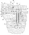
- FIG. 2is a sectional view of a portion of an injection molding system showing a heated nozzle according to a preferred embodiment of the present invention.
- FIG. 3is an enlarged sectional view of the nozzle of FIG. 2 .
- FIG. 4is a further enlarged and rotated (90° counter-clockwise) sectional view of the heater assembly of the nozzle of FIG. 2 .
- FIG. 5is an enlarged sectional view, similar to FIG. 4 , of an alternate embodiment of a nozzle heater assembly according to the present invention.
- FIG. 6is an enlarged sectional view, similar to FIG. 4 , of another alternate embodiment of a nozzle heater assembly according to the present invention.
- FIG. 7is an enlarged sectional view, similar to FIG. 4 , of a further alternate embodiment of a nozzle heater assembly according to the present invention.
- FIG. 8is an enlarged sectional view, similar to FIG. 4 , of a yet further alternate embodiment of a nozzle heater assembly according to the present invention.
- FIG. 9is an exploded isometric view of an alternate embodiment of the nozzle heater of the present invention.
- FIG. 10is a sectional view of a further embodiment of the nozzle heater of the present invention.
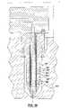
- FIG. 11is an enlarged sectional view of another nozzle embodiment employing a heater according to the present invention.
- FIG. 12 ais an isometric view of a straight wire element for use as a heater element of the present invention.
- FIG. 12 bis an isometric view of a coiled wire element for use as a heater element of the present invention.
- FIG. 13 ais an isometric view of a doubled and twisted straight wire element for use as a heater element of the present invention.
- FIG. 13 bis an isometric view of a doubled, coiled wire element for use as a heater element of the present invention.
- a multi-cavity injection molding system made in accordance with the present inventionis shown in the Figures generally at M.
- a melt passage 10extends from a common recessed inlet 12 in a manifold extension 14 to an elongated manifold 16 where it branches out to a number of outlets 18 .
- each branch 20 of melt passage 10extends through a steel nozzle 22 , having a central melt bore 24 in communication with melt passage outlet 18 from manifold 16 to a gate 26 leading to each cavity 28 .
- Nozzle 22is a heated nozzle having a heater 30 according to a preferred embodiment of the invention, as described in greater detail below.
- Manifold 16is heated by a heating element 32 which may be integrally brazed into it. Manifold 16 is held in place by a central locating ring 34 and insulating pressure pads 36 . Locating ring 34 bridges an insulative air space 38 between manifold 16 and a cooled spacer plate 40 . Pressure pads 36 provide another insulative air space 42 between manifold 16 and a cooled clamp plate 44 . Spacer plate 40 , clamp plate 44 and cavity plate 46 are cooled by pumping cooling water through a plurality of cooling conduits 48 . Clamp plate 44 and spacer plate 40 are secured in place by bolts 50 which extend into cavity plate 46 . Manifold extension 14 is held in place by screws 52 and a locating collar 54 which is secured to the clamp plate 44 by screws 56 .
- Each nozzle 22is seated in a well 58 in spacer plate 40 .
- An insulative air space 64is provided between heated nozzle 22 and the surrounding cooled spacer plate 40 .
- nozzle 22has a body 68 having a steel central core portion 70 , an outer surface 72 , and a tip 74 , which is seated in gate 26 .
- Tip 74has a flow channel 76 which is aligned with central melt bore 24 .
- Nozzle 22is seated and secured in manifold 16 by a threaded portion 78 .
- Heater assembly 30has an electrical resistive wire heating element 80 , having cold pin connections 82 for connecting wire element 80 to a power supply (not shown).
- Heater assembly 30also has a first insulating layer 84 and a second insulating layer 86 disposed on either side of wire element 80 , so as to “sandwich” element 80 therebetween.
- First layer 84is positioned on core 70 , with wire element 80 wrapped therearound, and second layer 86 positioned thereover.
- An outer steel layer 88is provided to finish nozzle 22 .
- Wire element 80is a simple, bare, electrically and thermally uninsulated wire, preferably of thirty (30) gauge chromium nickel, though any wire material having resistive heating characteristics may be employed.
- Wire element 80is preferably wrapped around nozzle 22 , and may be provided in any arrangement which provides the temperature distribution desired for a particular application. For example, in the embodiment of FIG. 3 , successive windings of wire element 80 are closer together at the ends of nozzle 22 , where more heat is typically required, with a more spaced distribution occurring in the central portion of nozzle 22 .
- first layer 84 and second layer 86are dielectric materials which can be applied in a “finished” (i.e. “non-green”) state to the nozzle body.
- the dielectric materialdoes not require additional heat treating steps once it is applied to the nozzle assembly, and thus has a chemical composition which does not change after it is applied to the apparatus and the material does not require heat treating of sintering to achieve its “finished” state.
- first layer 84is also preferably a dielectric material which can withstand the high operating temperatures and heater wattages experienced in hot runner injection molding.
- the dielectricis preferably a good thermal conductor with low heat capacity, a combination which encourages rapid heating (and cooling) with maximum efficiency.
- the dielectricshould also be a good electrical insulator, since wire element is otherwise uninsulated from nozzle 22 .
- the choice of materialdepends also on the temperature target for the molten material which will flow through the melt channel of the nozzle.
- Illustrative of the dielectric materials which can be used in the practice of this inventionare: aluminum oxide; magnesium oxide; mica coatings; VespelTM (trade mark of E.I. Du Pont de Nemour & Company); graphite; alumina; alumina-silica; zirconia-based materials, such as tetragonal zirconia polycrystals (TZP) partially stabilized zirconia (PSZ), fully stabilized zirconia (FSZ), transformation toughened ceramics (TTC), zirconia toughened alumina (ZTA) and transformation toughened zirconia (TTZ); Cerama-DipTM 538N (trade mark of Aremco Products Inc.), a zirconium silicate-filled water-based high temperature dielectric coating for use in insulating high-power resistors, coils and heaters; and CeramacoatTM 538N (trade mark of Aremco Products Inc.) is a silica based, high temperature dielectric coating for use in insulating induction heating coils
- Second layer 86is provided to protect wire element 80 from the deleterious effects of the atmosphere, such as oxidation and corrosion, and to insulate the exterior of nozzle 22 electrically and thermally, so as to direct the output of heater assembly 30 towards the melt in flow channel 76 .
- Second layer 86may be made from the same dielectric material as first layer 84 or a different material. In some applications, it may be desirable to use different materials.
- the first layer 84may be fabricated from a material having good electric insulating properties but high heat conductive characteristic, while the second layer 86 is of a material having high electric insulating properties and high heat insulating properties, so that the heat is directed to the central melt bore 24 within body 68 , while outer layer 88 remains cooler.
- the use of the same material, preferably aluminum oxide, for first layer 84 and second layer 86is preferred.
- First layer 84 and second layer 86may be provided as particles or a liquid sprayed onto the nozzle apparatus, as a liquid “painted” onto the apparatus or as a solid, pre-fabricated, self-supporting sleeve, as described in more detail below.
- the layersmay be provided in thicknesses as desired to suit a particular application. Thicknesses of the layers can range from 0.1 mm to 3 mm, and thicker, depending on the amount of insulating, overall nozzle diameter and method of fabrication desired, as will be described further below. Thicknesses in the range of 0.1 mm to 0.5 mm are preferred.
- Outer layer 88may be applied by spraying or by shrink-fitting a sleeve on second layer 86 .
- Outer layer 88may have any desired thickness, though a thickness of about 1.5 mm is preferred.
- a secondary wire element 90is provided around second layer 86 , protected by a third insulating layer 92 .
- second layer 86is preferably a good heat conductor and electrical insulator while third layer 92 is a dielectric having good thermal insulating characteristics.
- Third layer 92can be chosen from the same set of materials as described above for layers 84 and 86 . This embodiment permits a higher wattage heater to be obtained, at the obvious expense of a slightly larger nozzle diameter.
- secondary wire element 90can provide redundancy for operational use if and when the primary wire element fails.
- thermocouples 94 and 96show a configuration similar to FIG. 4 , but with integral temperature sensors or thermocouple wires 94 and 96 positioned between first layer 84 and second layer 86 , wound spirally around nozzle 22 adjacent wire element 80 . Inclusion of thermocouples 94 and 96 allow for exacting temperature control in nozzle 22 , as will be understood by one skilled in the art.
- the thermocouplesmay be disposed immediately adjacent wire element 80 , as shown in FIG. 6 , or may be provided between second layer 86 and third insulating layer 92 , as depicted in FIG. 7 . In this embodiment, second layer 86 and third layer 92 preferably have similar characteristics as described above for the FIG. 5 embodiment.
- a metal surface layer 98is provided on outer surface 72 , between nozzle core 70 and first layer 84 .
- Surface layer 98is a layer of a metal having a higher thermal conductivity than steel nozzle body 68 , such as copper and alloys of copper. Surface layer 98 thus promotes a more even distribution of heat from heater assembly 30 to the pressurized melt in central melt bore 24 .
- Surface layer 98may be applied by spraying or by shrink-fitting a sleeve on core 70 .
- Surface layer 98may have a thickness of between 0.1 mm to 0.5 mm, or greater if desired.
- nozzle 22 ′has a core 70 ′, a surface layer 98 ′ and a heater assembly 30 ′, which is composed of a first layer 84 ′, a wire element 80 ′, a second layer 86 ′ and an outer layer 88 ′.
- surface layer 98 ′, first layer 84 ′, second layer 86 ′ and outer layer 88 ′are, in fact, self-supporting, substantially rigid, annular telescoping sleeve components 98 a , 84 a , 86 a , and 88 a , respectively, which are pre-fabricated, prior to assembly of nozzle 22 ′, according to a method of the present invention, described below.
- This sleeve constructionpermits a heater assembly 30 ′ configuration which is selectively removable in part or in whole, depending on the design, from nozzle 22 ′ for periodic inspection, repair and/or replacement.
- this sleeve constructionpermits the nozzle body to expand independently from the insulating layers, by virtue of the separate and self-supporting nature of the heater sleeves.
- nozzle body 68is free to grow longitudinally while the insulating sleeves and wire, which typically have lower thermal expansion characteristics, will not be subject to a mechanical stress induced by this nozzle body expansion. This feature has beneficial implications for increased heater durability.
- the self-supporting annular sleeves of this embodimentmay be made of any suitable dielectric material, as described above, that can be machined, molded or extruded into a thin-walled tube. As with the previous embodiments, it is desirable that the coefficient of thermal transfer to be higher for inner sleeve than the outer sleeve. Both sleeves are preferably made of the same materials.
- first layer 84 ′is provided as a self-supporting sleeve
- second layer 86may be applied directly to first layer 84 (and over wire element 80 , as well) by spraying or other coating method, as described further below.
- first layer 84onto the nozzle body, and provide second layer 86 in a sleeve format.
- wire element 80 ′may be integrally provided on the interior of the second layer sleeve element, so as to be removable therewith.
- Other combinations of layer constructionare equally possible, as described below.
- heater assembly 30 ′′is disposed centrally within nozzle 22 ′′.
- Heater 30 ′′has a core 70 ′′, first layer 84 ′′, wire element 80 ′′, second layer 86 ′′ and outer layer 88 ′′.
- a removable nozzle tip 74 ′′is provided to permit heater assembly 30 ′′ to be removed from nozzle 22 ′′ for inspection, repair or replacement, as described above.
- the present inventionmay be employed in any known injection molding nozzle design.
- FIG. 11a two-part nozzle configuration according to the present invention is shown.
- a forward nozzle 100has a heater assembly 102 according to the present invention, as described above, and a rearward nozzle 104 has a heater 106 according to the prior art, such as, for example, as is described in U.S. Pat. No. 5,051,086 to Gellert, incorporated herein by reference.
- Heater assembly 102has a wire element 110 , a first insulating layer 112 and second insulating layer 114 , similar to that described above.
- Element 80can be effectively doubled by folding over the wire element, and optionally twisted, to create a unitary element 124 .
- Element 124has twice the length of wire for a given element 80 length, and is twice as thick.
- a coiled and doubled element 126can equally be provided.
- wire element 80is energized by a power source (not shown). As current flows through wire element 80 , resistance to the electrical flow causes the wire to heat, as is well understood in the art. Heat generated by the element is preferably channeled and expelled substantially inwardly, by the presence first insulating layer 84 and second layer 86 , to heat the pressurized melt in central melt bore 76 . First layer 84 and second layer 86 also provide electrical insulation to electrically isolate wire element 80 from the surrounding metal components of the nozzle.
- the uninsulated resistive wire heating element according to the present inventionpermits a cheaper heater to be obtained while permitting more exacting temperature distribution and control through more precise and flexible positioning of the element. Unlike the prior art, complex machining of the nozzle body and the need for integrally brazing the heating element to the nozzle body are removed, permitting savings in cost and time in fabricating the nozzle. Likewise, special and complex film printing techniques, materials and machinery are not required. Further, and perhaps most importantly, the present invention permits smaller diameter heated nozzle designs to be more easily achieved and more reliably operated than is possible with the prior art.
- the heated nozzles of the present inventionmay be fabricated according to the method of the present invention.
- steel nozzle body 68is provided as the substrate for spraying first layer 84 thereon.
- First layer 84may be provided by spraying, “painting” or otherwise coating in a thickness of between 0.1 mm and 0.5 mm. While greater thicknesses are possible, little benefit is attained by providing a thickness greater than 0.5 mm and, since it is generally desirable to minimize nozzle diameter, greater thicknesses are not typically preferred.
- First layer 84is provided on outer surface 72 of nozzle body 68 so as to substantially cover, and preferably completely cover, outer surface 72 over the region where wire element 80 is to be located.
- wire element 80is then positioned around first layer 84 , preferably by winding wire element 80 spirally around the exterior of the nozzle. Although any wire pattern is possible, winding is typically preferred because, among other things, it requires the simplest operation in automated production.
- second layer 86is then provided so as to substantially cover, and preferably completely cover, wire element 80 and thereby sandwich and encase wire element 80 between first layer 84 and second layer 86 .
- Second layer 86is preferably applied by spraying, “painting” or otherwise coating to a thickness of between 0.1 mm and 0.5 mm (for reasons described above), though any other method of applying second layer 86 may be employed, including providing a sleeve as described below.
- metal outer layer 88is provided.
- Metal outer layer 88may be applied in any known manner, such as by spraying or by shrink-fitting a sleeve, with spraying being preferred in this embodiment to minimize the overall diameter of the nozzle. With the outer layer applied, the assembly is then typically swaged to compact the assembly and bring the overall nozzle diameter to within desired dimensional tolerances.
- This embodiment of the methodpermits smaller diameter and more durable nozzles to be obtained than is possible with the prior art. Further, the method is advantageous over the prior art since no additional heat treating step is required, thereby simplifying manufacture.
- first layer 84is provided as a pre-fabricated, self-supporting, substantially rigid, annular sleeve component which is telescopically, slidably positioned concentrically over core 70 .
- the sleeve elementmay be cast, machined, molded or extruded into a thin-walled tube, and may be provided in any desired thickness, though thicknesses in the range of 1.5 mm to 2 mm are preferred to optimize thickness and durability of the sleeve component.
- the inside diameter of the first layer sleeveis preferably as small as possible while still permitting a sliding installation over core 70 , so as to minimize any air space between the two components.
- the next stepis to position wire element 80 around the first layer sleeve and, as one skilled in the art will understand, it is not important whether the wire element is positioned around the first layer sleeve prior or subsequent to the sleeve's installation on the nozzle body.
- an advantage of the method of this embodimentis that the wire element can be pre-wired on the first layer sleeve prior to installation, which can offer flexibility and simplification in manufacturing.
- Second layer 86may be applied as a sleeve or by spraying, with the sleeve form being preferred in this embodiment. Again, it is not important whether second layer 86 is applied prior or subsequent to the installation of the first layer sleeve on the nozzle body. Second layer 86 , if applied in sleeve format, is sized to fit as closely as possible over wire element 80 on the first layer sleeve to minimize the air space between the first and second layers. A metal outer layer 88 is then applied to the outside of second layer 86 and may be applied by any known means, such as by spraying or by shrink-fitting a sleeve, with shrink-fitting a sleeve being preferred in this embodiment.
- the outer layermay be applied to the second layer sleeve either pre- or post-installation of the second layer sleeve on the first layer sleeve or the nozzle assembly. With the outer layer applied, the assembly is then typically swaged to compact the assembly and bring the overall nozzle diameter to within desired dimensional tolerances. The assembly is then finished as required. Such finishing steps may include providing removable nozzle tip 74 to the nozzle assembly, if necessary in the particular application.
- This embodiment of the methodpermits a removable heater assembly to be achieved.
- the first layer sleeve and/or second layer sleevecan be selectively removed from the nozzle body for inspection and/or replacement, if the heater is damaged or worn, without the need to replace the entire nozzle.
- the independent nature of the sleeve elementspermits the order of assembly to be varied as necessary, for example, by allowing the wire element to be provided on the first layer sleeve prior to installation on the nozzle body.
- the second layermay be provided on first sleeve, over the installed wire, prior to installation of the first layer sleeve on the nozzle body. This advantage offers not only flexibility in manufacture but also permits the wire element to be more precisely placed on the first layer sleeve.
- laying the wire over the sleeve and then spinning the sleeve so as to wind the wire onto the sleevepermits a precisely controlled pitch and pitch variation.
- a further advantage of the methodis that no additional heat treating step is required, thereby simplifying manufacture.
- wire element 80can equally be pre-installed in the interior of a second layer sleeve, rather than the outside of first layer sleeve.
- a metal surface layer 98 of copper or other highly thermally conductive metalmay be applied with advantage to the nozzle body prior to providing the first insulating layer, as described above with respect to the apparatus.
- the surface layeris applied by spraying.
- the surface layeris provided by shrink-fitting a sleeve onto core 70 of nozzle body 68 . As described above, the surface layer promotes thermal transfer between heater 30 and nozzle body 68 .
Landscapes
- Engineering & Computer Science (AREA)
- Mechanical Engineering (AREA)
- Manufacturing & Machinery (AREA)
- Injection Moulding Of Plastics Or The Like (AREA)
- Moulds For Moulding Plastics Or The Like (AREA)
- Physical Or Chemical Processes And Apparatus (AREA)
Abstract
Description
Claims (25)
Priority Applications (1)
| Application Number | Priority Date | Filing Date | Title |
|---|---|---|---|
| US11/685,266US7438551B2 (en) | 2000-03-08 | 2007-03-13 | Compact cartridge hot runner nozzle |
Applications Claiming Priority (5)
| Application Number | Priority Date | Filing Date | Title |
|---|---|---|---|
| US09/520,843US6394784B1 (en) | 2000-03-08 | 2000-03-08 | Compact cartridge hot runner nozzle |
| US10/025,767US6638053B2 (en) | 2000-03-08 | 2001-12-26 | Compact cartridge hot runner nozzle |
| US10/601,190US7108502B2 (en) | 2000-03-08 | 2003-06-23 | Hot runner nozzle with interlaced heater and sensor |
| US11/510,994US7377768B2 (en) | 2000-03-08 | 2006-08-28 | Hot runner nozzle with removable sleeve |
| US11/685,266US7438551B2 (en) | 2000-03-08 | 2007-03-13 | Compact cartridge hot runner nozzle |
Related Parent Applications (1)
| Application Number | Title | Priority Date | Filing Date |
|---|---|---|---|
| US11/510,994DivisionUS7377768B2 (en) | 2000-03-08 | 2006-08-28 | Hot runner nozzle with removable sleeve |
Publications (2)
| Publication Number | Publication Date |
|---|---|
| US20070154588A1 US20070154588A1 (en) | 2007-07-05 |
| US7438551B2true US7438551B2 (en) | 2008-10-21 |
Family
ID=24074298
Family Applications (8)
| Application Number | Title | Priority Date | Filing Date |
|---|---|---|---|
| US09/520,843Expired - LifetimeUS6394784B1 (en) | 2000-03-08 | 2000-03-08 | Compact cartridge hot runner nozzle |
| US10/025,768Expired - LifetimeUS6561789B2 (en) | 2000-03-08 | 2001-12-26 | Compact cartridge hot runner nozzle |
| US10/025,767Expired - LifetimeUS6638053B2 (en) | 2000-03-08 | 2001-12-26 | Compact cartridge hot runner nozzle |
| US10/465,804Expired - LifetimeUS6761557B2 (en) | 2000-03-08 | 2003-06-20 | Compact cartridge hot runner nozzle |
| US10/601,190Expired - LifetimeUS7108502B2 (en) | 2000-03-08 | 2003-06-23 | Hot runner nozzle with interlaced heater and sensor |
| US11/510,994Expired - Fee RelatedUS7377768B2 (en) | 2000-03-08 | 2006-08-28 | Hot runner nozzle with removable sleeve |
| US11/681,593Expired - Fee RelatedUS7413432B2 (en) | 2000-03-08 | 2007-03-02 | Compact cartridge hot runner nozzle |
| US11/685,266Expired - Fee RelatedUS7438551B2 (en) | 2000-03-08 | 2007-03-13 | Compact cartridge hot runner nozzle |
Family Applications Before (7)
| Application Number | Title | Priority Date | Filing Date |
|---|---|---|---|
| US09/520,843Expired - LifetimeUS6394784B1 (en) | 2000-03-08 | 2000-03-08 | Compact cartridge hot runner nozzle |
| US10/025,768Expired - LifetimeUS6561789B2 (en) | 2000-03-08 | 2001-12-26 | Compact cartridge hot runner nozzle |
| US10/025,767Expired - LifetimeUS6638053B2 (en) | 2000-03-08 | 2001-12-26 | Compact cartridge hot runner nozzle |
| US10/465,804Expired - LifetimeUS6761557B2 (en) | 2000-03-08 | 2003-06-20 | Compact cartridge hot runner nozzle |
| US10/601,190Expired - LifetimeUS7108502B2 (en) | 2000-03-08 | 2003-06-23 | Hot runner nozzle with interlaced heater and sensor |
| US11/510,994Expired - Fee RelatedUS7377768B2 (en) | 2000-03-08 | 2006-08-28 | Hot runner nozzle with removable sleeve |
| US11/681,593Expired - Fee RelatedUS7413432B2 (en) | 2000-03-08 | 2007-03-02 | Compact cartridge hot runner nozzle |
Country Status (8)
| Country | Link |
|---|---|
| US (8) | US6394784B1 (en) |
| EP (3) | EP1263563B1 (en) |
| JP (1) | JP2003525781A (en) |
| AT (1) | ATE280025T1 (en) |
| AU (1) | AU2001240393A1 (en) |
| CA (4) | CA2580974C (en) |
| DE (3) | DE20122253U1 (en) |
| WO (1) | WO2001066333A1 (en) |
Cited By (2)
| Publication number | Priority date | Publication date | Assignee | Title |
|---|---|---|---|---|
| US20100303945A1 (en)* | 2009-05-28 | 2010-12-02 | Citriniti Joseph H | Devices And Methods For Regulating Extruder Ceramic Batch Material |
| WO2013043307A1 (en)* | 2011-09-20 | 2013-03-28 | Husky Injection Molding Systems Ltd. | Mold-tool system including component having, at least in part, anodized aluminum material coupled to electrically-resistive heating element |
Families Citing this family (61)
| Publication number | Priority date | Publication date | Assignee | Title |
|---|---|---|---|---|
| NL1012925C2 (en)* | 1999-08-27 | 2001-02-28 | Franciscus Antonius Jozef Van | Injection molding device. |
| US6394784B1 (en)* | 2000-03-08 | 2002-05-28 | Mold-Masters Limited | Compact cartridge hot runner nozzle |
| CA2311829A1 (en)* | 2000-06-16 | 2001-12-16 | Jonathon Fischer | Thermally balanced hot runner nozzle |
| US7616997B2 (en) | 2000-09-27 | 2009-11-10 | Kieval Robert S | Devices and methods for cardiovascular reflex control via coupled electrodes |
| ITTO20010399A1 (en)* | 2001-04-27 | 2002-10-27 | Attrezzature Speciali Srl As | NOZZLE FOR INJECTION MOLDS OF PLASTIC MATERIALS. |
| AU2003202931A1 (en) | 2002-01-09 | 2003-07-30 | Mold-Masters Limited | Method and apparatus for measuring the temperature of molten material in a mold cavity |
| KR100500692B1 (en)* | 2002-03-12 | 2005-07-12 | 비오이 하이디스 테크놀로지 주식회사 | A liquid crystal display device which accomplishes both image display mode and fingerprint recognition mode |
| KR20040000735A (en)* | 2002-06-25 | 2004-01-07 | 김혁중 | heater for injection molding |
| US7510392B2 (en) | 2002-11-06 | 2009-03-31 | Mold-Masters (2007) Limited | Injection nozzle with a removable heater device having one or more heating elements |
| JP2005132075A (en)* | 2002-11-06 | 2005-05-26 | Mold Masters Ltd | Injection nozzle equipped with lamellar heater |
| US6854971B2 (en)* | 2002-11-07 | 2005-02-15 | Husky Injection Molding Systems Ltd. | Apparatus for retaining a heater on an injection molding nozzle |
| US20050181090A1 (en)* | 2002-12-06 | 2005-08-18 | Mold-Masters Limited | Injection molding nozzle with embedded and removable heaters |
| US7118704B2 (en)* | 2002-12-13 | 2006-10-10 | Mold-Masters Limited | Nozzle and method for making a nozzle with a removable and replaceable heating device |
| ITTO20030042A1 (en)* | 2003-01-27 | 2004-07-28 | Piero Enrietti | HEATER-DIFFUSER DEVICE FOR A THERMAL NOZZLE |
| US7143496B2 (en)* | 2003-05-08 | 2006-12-05 | Mold-Masters Limited | Hot runner nozzle with removable tip and tip retainer |
| US20050069604A1 (en)* | 2003-06-20 | 2005-03-31 | Fast Heat, Inc. | Hot runner component heater having thermal sprayed resistive element |
| US7342206B2 (en)* | 2004-01-06 | 2008-03-11 | Watlow Electric Manufacturing Company | Tailored heat transfer layered heater system |
| US20050255189A1 (en)* | 2004-05-17 | 2005-11-17 | Manda Jan M | Method and apparatus for coupling melt conduits in a molding system and/or a runner system |
| ITTO20040717A1 (en)* | 2004-10-15 | 2005-01-15 | Incos Spa | INJECTOR FOR PLASTIC INJECTION MOLDING EQUIPMENT |
| US20060127548A1 (en)* | 2004-12-10 | 2006-06-15 | Hideko Nakanishi | Apparatus and method for dispensing a softened edible substance for decorating foodstuffs |
| DE102005007398B3 (en)* | 2005-02-18 | 2006-09-21 | Incoe International, Inc. | Heating cylinder for pushing onto a spray nozzle for an injection molding plant |
| ITTO20050158A1 (en)* | 2005-03-11 | 2006-09-12 | Incos Spa | ENERGY CONTROL SYSTEM FOR PLASTIC INJECTION MOLDING EQUIPMENT |
| DE602006015565D1 (en)* | 2005-05-19 | 2010-09-02 | Mold Masters Ltd | Injection molding nozzle with a thermally conductive sleeve and method for its production |
| US7280750B2 (en)* | 2005-10-17 | 2007-10-09 | Watlow Electric Manufacturing Company | Hot runner nozzle heater and methods of manufacture thereof |
| ITTO20050841A1 (en)* | 2005-11-29 | 2007-05-30 | Incos Spa | THERMOREGULATION SYSTEM FOR HEATED COMPONENTS OF PLASTIC INJECTION MOLDING EQUIPMENT |
| WO2007100222A1 (en)* | 2006-03-03 | 2007-09-07 | Mold-Inno Co., Ltd. | Non-contact high-frequency induction heating apparatus for plastic mold and injection nozzle thereof |
| KR100733001B1 (en)* | 2006-03-29 | 2007-06-29 | 삼성광주전자 주식회사 | Injection device |
| US20080095876A1 (en)* | 2006-08-11 | 2008-04-24 | Husky Injection Molding Systems Ltd. | Seal of a barrel assembly |
| ITTO20060716A1 (en)* | 2006-10-06 | 2008-04-07 | Inglass Spa | INJECTOR FOR PLASTIC INJECTION MOLDING |
| DE102006049669A1 (en) | 2006-10-18 | 2008-04-24 | Günther Heisskanaltechnik Gmbh | Electric heating device for hot runner systems |
| ATE544573T1 (en)* | 2006-12-29 | 2012-02-15 | Mold Masters 2007 Ltd | INJECTION MOLDING DEVICE WITH SIDE GATE OPENING |
| US20080224817A1 (en)* | 2007-03-15 | 2008-09-18 | Sokudo Co., Ltd. | Interlaced rtd sensor for zone/average temperature sensing |
| JP5114080B2 (en)* | 2007-03-20 | 2013-01-09 | 東洋機械金属株式会社 | Injection molding machine |
| US7800021B2 (en)* | 2007-06-30 | 2010-09-21 | Husky Injection Molding Systems Ltd. | Spray deposited heater element |
| DE102007051694A1 (en) | 2007-10-26 | 2009-04-30 | Justus-Liebig-Universität Giessen | Copper-oxygen adduct |
| CN101946558B (en)* | 2008-02-20 | 2013-11-06 | 住友化学株式会社 | Heater, resin molding device, resin molding method, and resin molded body |
| US9289795B2 (en) | 2008-07-01 | 2016-03-22 | Precision Coating Innovations, Llc | Pressurization coating systems, methods, and apparatuses |
| PT2328735T (en)* | 2008-07-14 | 2018-03-22 | Synventive Molding Solutions Inc | Injection molding flow control apparatus |
| US20100015456A1 (en) | 2008-07-16 | 2010-01-21 | Eastman Chemical Company | Thermoplastic formulations for enhanced paintability toughness and melt process ability |
| DE102008036836A1 (en)* | 2008-08-07 | 2010-02-11 | Epcos Ag | Shaped body, heating device and method for producing a shaped body |
| DE102008036835A1 (en) | 2008-08-07 | 2010-02-18 | Epcos Ag | Heating device and method for producing the heating device |
| US8734909B2 (en)* | 2010-03-10 | 2014-05-27 | Eastman Chemical Company | Methods and apparatus for coating substrates |
| CN103347668A (en)* | 2011-02-16 | 2013-10-09 | 赫斯基注塑系统有限公司 | Mold-tool system including cooling-insert assembly being positioned proximate to nozzle assembly |
| DE102012102549A1 (en)* | 2011-11-15 | 2013-05-16 | Ferrofacta Gmbh | Die casting nozzle and method for operating the die casting nozzle |
| US9616457B2 (en) | 2012-04-30 | 2017-04-11 | Innovative Coatings, Inc. | Pressurization coating systems, methods, and apparatuses |
| US10541183B2 (en) | 2012-07-19 | 2020-01-21 | Texas Instruments Incorporated | Spectral reflectometry window heater |
| WO2014043088A1 (en)* | 2012-09-13 | 2014-03-20 | Husky Injection Molding Systems Ltd. | A melt distribution device |
| US8865261B2 (en)* | 2012-12-06 | 2014-10-21 | Eastman Chemical Company | Extrusion coating of elongated substrates |
| US9987782B2 (en)* | 2013-09-10 | 2018-06-05 | Otto Männer Innovation GmbH | Hot runner nozzle with a segmented heater |
| US9573435B2 (en)* | 2013-09-29 | 2017-02-21 | Elka Suspension Inc. | Dual inline hydraulic device |
| US9920526B2 (en) | 2013-10-18 | 2018-03-20 | Eastman Chemical Company | Coated structural members having improved resistance to cracking |
| US9744707B2 (en) | 2013-10-18 | 2017-08-29 | Eastman Chemical Company | Extrusion-coated structural members having extruded profile members |
| US9574510B2 (en)* | 2015-03-03 | 2017-02-21 | Ford Global Technologies, Llc | Methods and systems for estimating exhaust pressure with a variable voltage oxygen sensor |
| ITUB20152262A1 (en)* | 2015-07-17 | 2017-01-17 | Inglass Spa | NOZZLE TERMINAL FOR PLASTIC INJECTION MOLDING INJECTORS OF PLASTIC MATERIALS |
| DE102015112748A1 (en)* | 2015-08-03 | 2017-02-09 | Günther Heisskanaltechnik Gmbh | Heating element for a flow channel or a mold cavity and injection molding with such a heating element |
| DE202015104723U1 (en)* | 2015-09-04 | 2015-09-18 | Türk & Hillinger GmbH | Electric heating cartridge with temperature monitoring and electric heating with temperature monitoring |
| US11584078B2 (en)* | 2017-10-03 | 2023-02-21 | Jabil Inc. | Apparatus, system and method of operating an additive manufacturing nozzle |
| JP6695038B2 (en)* | 2018-01-25 | 2020-05-20 | 新熱工業株式会社 | Heating element, fluid heater, and method for manufacturing heating element |
| US12246476B2 (en)* | 2018-06-25 | 2025-03-11 | Husky Injection Molding Systems Ltd. | Nozzle with removable nozzle tip configured for improved heating |
| AU2021290207B1 (en)* | 2021-12-20 | 2023-02-02 | 3rd Axis Pty Ltd | High Temperature Extruder for a 3D Printer |
| JP2024032159A (en)* | 2022-08-29 | 2024-03-12 | セイコーエプソン株式会社 | Material dispensing equipment, nozzles and plasticizing equipment |
Citations (97)
| Publication number | Priority date | Publication date | Assignee | Title |
|---|---|---|---|---|
| US2088586A (en) | 1935-06-29 | 1937-08-03 | Air Conditioners Inc | Immersion heater |
| US2378530A (en) | 1942-02-18 | 1945-06-19 | Standard Oil Co | Catalytic hydrocarbon conversion process |
| US2522365A (en) | 1949-01-07 | 1950-09-12 | Edward S Greene | Extrusion machine cylinder |
| US2769201A (en) | 1948-07-01 | 1956-11-06 | Lorenian Zareh | Screw extrusion apparatus for manufacturing articles of thermoplastic and thermosetting materials |
| US2794504A (en) | 1954-05-10 | 1957-06-04 | Union Oil Co | Well heater |
| US2814070A (en) | 1955-05-05 | 1957-11-26 | Standard Oil Co | Plastic extruder |
| US2875312A (en) | 1956-09-27 | 1959-02-24 | Thermel Inc | Heating assembly and method of production thereof |
| US2987300A (en) | 1959-05-29 | 1961-06-06 | Edward G S Greene | Heat transfer assembly |
| US2991423A (en) | 1958-02-19 | 1961-07-04 | Tesla Np | Low-frequency regenerative amplifier |
| US3062940A (en) | 1958-02-17 | 1962-11-06 | Sud West Chemie G M B H | Welding fitting |
| US3550267A (en) | 1967-10-09 | 1970-12-29 | Harry H Williams | Method of fabricating a heating element |
| US3553788A (en) | 1968-09-10 | 1971-01-12 | Ladislao Wladyslaw Putkowski | Hot runner system for plastic injection molds |
| US3677682A (en) | 1970-03-09 | 1972-07-18 | Ladislao Wladyslaw Putkowski | Hot runner system |
| US3800027A (en) | 1971-02-17 | 1974-03-26 | S Tsutsumi | Injection molding apparatus for synthetic resin |
| US3812323A (en) | 1972-11-03 | 1974-05-21 | Ford Motor Co | Electrical heating bands for a feeding system |
| US3831004A (en) | 1973-07-27 | 1974-08-20 | Fast Heat Element Mfg Co | Electric heater |
| US3849630A (en) | 1971-10-18 | 1974-11-19 | Pyrotenax Ltd | Electric heating device |
| US3911251A (en) | 1973-11-05 | 1975-10-07 | Charles L Day | Heating device for molding |
| US3912907A (en) | 1974-07-19 | 1975-10-14 | Fast Heat Element Mfg Co | Clamp and mounting electric heater with a cable |
| US3970821A (en) | 1974-10-21 | 1976-07-20 | Fast Heat Element Manufacturing Co., Inc. | Electrically heated torpedo |
| US4032046A (en) | 1976-11-01 | 1977-06-28 | Usm Corporation | Apparatus for feeding glue to a hot melt glue dispensing appliance |
| US4238671A (en) | 1979-05-08 | 1980-12-09 | Gellert Jobst U | Sprue bushing with cast in heater element |
| US4268241A (en) | 1978-01-06 | 1981-05-19 | Husky Injection Molding Systems | Heated injection nozzle |
| US4304544A (en) | 1974-10-21 | 1981-12-08 | Fast Heat Element Mfg. Co., Inc. | Electrically heated nozzles and nozzle systems |
| US4373132A (en) | 1981-08-05 | 1983-02-08 | Haig Vartanian | External/internal heater for molding of plastics |
| US4376244A (en) | 1981-05-08 | 1983-03-08 | Gellert Jobst U | Injection molding heated probe |
| US4386262A (en) | 1980-10-24 | 1983-05-31 | Gellert Jobst U | Sprue bushing with cast in electrical heating element |
| US4403405A (en) | 1981-07-15 | 1983-09-13 | Gellert Jobst U | Sprue bushing connector assembly method |
| US4438322A (en) | 1981-06-16 | 1984-03-20 | Pace Incorporated | Ceramic coated electric heater assembly for tools |
| US4438064A (en) | 1981-11-20 | 1984-03-20 | Shigeru Tsutsumi | Injection molding process for synthetic resin and its apparatus |
| US4485387A (en) | 1982-10-26 | 1984-11-27 | Microscience Systems Corp. | Inking system for producing circuit patterns |
| US4492556A (en) | 1978-10-16 | 1985-01-08 | Fast Heat Element Mfg. Co., Inc. | Unitary heated nozzle assembly |
| DE3324901A1 (en) | 1983-07-09 | 1985-01-24 | Hotset Heizpatronen und Zubehör GmbH, 5880 Lüdenscheid | DEVICE FOR ELECTRIC HEATING AND COOLING BY MEANS OF LIQUID MEDIA FOR PLASTIC SPRAYING MACHINES |
| US4501550A (en) | 1981-12-02 | 1985-02-26 | Shigeru Tsutsumi | Cap means for preventing resin from remaining in a mold of a runnerless injection molding apparatus |
| US4516927A (en) | 1980-06-25 | 1985-05-14 | Shigeru Tsutsume | Pointed heat-generating device for molds of injection molding machines |
| US4557685A (en) | 1984-07-13 | 1985-12-10 | Gellert Jobst U | Heated nozzle for injection molding apparatus |
| US4588367A (en) | 1984-07-16 | 1986-05-13 | Husky Injection Molding Systems Ltd. | Hot runner manifold for injection molding machine |
| US4621251A (en) | 1985-03-28 | 1986-11-04 | North American Philips Corp. | Electric resistance heater assembly |
| DE8620956U1 (en) | 1986-08-05 | 1986-11-27 | Jetform Heißkanalnormalien und Zubehör GmbH, 7255 Rutesheim | Device for electrical heating of hot runner nozzles |
| US4635851A (en) | 1983-09-19 | 1987-01-13 | Pegasus Industries, Inc. | Casting nozzle |
| US4641423A (en) | 1974-10-21 | 1987-02-10 | Fast Heat Element Manufacturing Co., Inc. | Method of making electrically heated nozzles and nozzle systems |
| US4644140A (en) | 1983-12-27 | 1987-02-17 | Turk & Hillinger Gmbh | Electric heating arrangement for spray nozzles |
| US4652230A (en) | 1985-05-06 | 1987-03-24 | Osuna Diaz J M | Injection molding nozzle |
| US4704516A (en) | 1984-08-31 | 1987-11-03 | Shigeru Tsutsumi | Pointed heat-generating device for molds of injection molding machines |
| US4711625A (en) | 1985-07-19 | 1987-12-08 | Joachim F. Knauer | Nozzle cartridge for injection molding |
| US4740674A (en) | 1985-12-16 | 1988-04-26 | Sanri Kabushiki Kaisha | Pointed heat-generating device |
| US4768283A (en) | 1987-07-15 | 1988-09-06 | Gellert Jobst U | Coated injection molding nozzle and method |
| US4771164A (en) | 1987-04-01 | 1988-09-13 | Gellert Jobst U | Injection molding nozzle and method |
| US4795126A (en) | 1978-10-16 | 1989-01-03 | Fast Heat Element Manufacturing Co., Inc. | Electrically heated nozzles and nozzle systems |
| JPS6458518A (en) | 1987-08-31 | 1989-03-06 | Fanuc Ltd | Nozzle apparatus of injection molding machine |
| US4837925A (en) | 1988-09-30 | 1989-06-13 | Gellert Jobst U | Method of manufacture of an electrical terminal on an injection molding nozzle |
| US4865535A (en) | 1988-04-13 | 1989-09-12 | Gellert Jobst U | Injection molding nozzle having multiple thickness heating element |
| US4882469A (en) | 1988-09-28 | 1989-11-21 | Panos Trakas | Internally heated sprue bushing assembly with a unitary bushing casing core element |
| US4894197A (en) | 1987-03-26 | 1990-01-16 | Sanri Kabushiki Kaisha | Method for runnerless injection molding synthetic resin by intermittent cooling system and apparatus thereof |
| US4911636A (en) | 1988-09-30 | 1990-03-27 | Gellert Jobst U | Injection molding nozzle having nose portion with heating element encircling the bore |
| US4945630A (en) | 1990-01-19 | 1990-08-07 | Gellert Jobst U | Method of making a selected size injection molding nozzle |
| US4981431A (en) | 1989-07-13 | 1991-01-01 | Mold-Masters Limited | Injection molding system with flanged insulating gate seal |
| US4988848A (en) | 1988-09-28 | 1991-01-29 | Panos Trakas | Ceramic heater element for dual zone sprue bushing |
| EP0444748A1 (en) | 1990-03-01 | 1991-09-04 | Eurotool B.V. | Process for the production of an injection nozzle for use in an injection moulding device |
| US5051086A (en) | 1990-07-27 | 1991-09-24 | Gellert Jobst U | Insulated injection molding nozzle |
| US5055028A (en) | 1989-04-07 | 1991-10-08 | Panos Trakas | Internally heated torpedo with internal melt distribution chamber |
| DE9201797U1 (en) | 1992-02-13 | 1992-04-09 | Türk & Hillinger GmbH, 7200 Tuttlingen | Plastic spray nozzle with tubular heater and integrated thermocouple |
| US5136141A (en) | 1990-10-31 | 1992-08-04 | Melt Design, Inc. | Integral sprue bushing assembly |
| US5136143A (en) | 1991-06-14 | 1992-08-04 | Heatron, Inc. | Coated cartridge heater |
| US5147663A (en) | 1990-10-09 | 1992-09-15 | Panos Trakas | Modular manifold assembly |
| US5225211A (en) | 1990-09-12 | 1993-07-06 | Nippondenso Co., Ltd. | Hot runner injection molding machine |
| US5226596A (en) | 1991-02-19 | 1993-07-13 | Mold-Masters Kabushiki Kaisha | Heated nozzle for plastic injection and manufacturing method therefor |
| US5235737A (en) | 1991-12-13 | 1993-08-17 | Gellert Jobst U | Method of making an injection molding nozzle with a heating element extending outward between adjacent collar portions |
| US5266023A (en) | 1992-09-30 | 1993-11-30 | Craig W. Renwick | Injection molding nozzle having an electrical terminal with an insulative connector. |
| US5282735A (en) | 1992-11-19 | 1994-02-01 | Gellert Jobst U | Injection molding nozzle with partially unheated heating element |
| EP0590621A1 (en) | 1992-09-30 | 1994-04-06 | Husky Injection Molding Systems Ltd. | Band heater clamp arrangement |
| DE4242505A1 (en) | 1992-12-16 | 1994-06-23 | Hotset Heizpatronen Zubehoer | Electric heating body for injection moulds |
| US5326251A (en) | 1993-12-06 | 1994-07-05 | Gellert Jobst U | Heated injection molding nozzle with alternate thermocouple bores |
| US5411393A (en) | 1993-01-04 | 1995-05-02 | Southwire Company | Premix burner for furnace with gas enrichment |
| US5456592A (en) | 1993-02-16 | 1995-10-10 | Seiki Kabushiki Kaisha | Injection mold probe and runnerless injection mold |
| US5504304A (en) | 1994-08-24 | 1996-04-02 | Seiki Kabushiki Kaisha | Hot runner probe and its equipment |
| US5518389A (en) | 1991-10-16 | 1996-05-21 | Kao Corporation | Multi-cavity mold apparatus having independently controlled heated runners |
| US5527177A (en) | 1994-06-07 | 1996-06-18 | Potter; Edward J. | Tip heater for a runnerless injection molding probe |
| EP0748678A1 (en) | 1995-06-12 | 1996-12-18 | EUROTOOL Beheer B.V. | Sprue bushing with heater element |
| US5614233A (en) | 1995-06-26 | 1997-03-25 | Gellert; Jobst U. | Injection molding nozzle with pressed in heating element and integral collar portion |
| EP0765728A2 (en) | 1995-09-26 | 1997-04-02 | Krupp Kunststofftechnik GmbH | Nozzle body for an injection nozzle |
| US5704113A (en) | 1996-07-24 | 1998-01-06 | Mold-Masters Limited | Injection molding nozzle method using a terminal locating and sealing key |
| US5820900A (en) | 1996-08-21 | 1998-10-13 | Mcgrevy; Alan N. | Heating device for an injection mold apparatus |
| US5871786A (en) | 1997-04-04 | 1999-02-16 | Kona Corporation | Tip heated hot runner nozzle |
| US5955120A (en) | 1994-03-01 | 1999-09-21 | Dme Normalien Gmbh | Heating device, in particular for use in injection molds for the processing of thermoplastic materials |
| US5973296A (en) | 1998-10-20 | 1999-10-26 | Watlow Electric Manufacturing Company | Thick film heater for injection mold runner nozzle |
| EP0963829A1 (en) | 1998-06-12 | 1999-12-15 | Husky Injection Molding Systems Ltd. | Molding system using film heaters and/or sensors |
| US6040528A (en) | 1993-10-18 | 2000-03-21 | Fuji Electric Co., Ltd. | Insulating supporting structure for high-voltage apparatus including inorganic insulating layer formed on a surface of an organic insulating structure |
| DE19941038A1 (en) | 1999-08-28 | 2001-03-01 | Guenther Heiskanaltechnik Gmbh | Electric heater for hot runner systems and method for producing such a heater |
| WO2001015884A3 (en) | 1999-08-27 | 2001-05-17 | Boekel Franciscus Antonius Joz | Injection-moulding device |
| US6394784B1 (en) | 2000-03-08 | 2002-05-28 | Mold-Masters Limited | Compact cartridge hot runner nozzle |
| EP1252998A3 (en) | 2001-04-27 | 2003-04-23 | Quaser S.r.L | Nozzle for injection moulding of plastic materials |
| US6649095B2 (en) | 2000-11-06 | 2003-11-18 | Frederick J. Buja | Method and apparatus for controlling a mold melt-flow process using temperature sensors |
| US6780003B2 (en) | 2002-08-02 | 2004-08-24 | Mold-Masters Limited | Removable heater for a hot runner nozzle |
| US6805549B2 (en) | 2000-01-31 | 2004-10-19 | Gunther Heisskanal Technik Gmbh | Nozzle for injection moulding tool and nozzle arrangement |
| US6854971B2 (en) | 2002-11-07 | 2005-02-15 | Husky Injection Molding Systems Ltd. | Apparatus for retaining a heater on an injection molding nozzle |
| US7147458B2 (en) | 2002-10-25 | 2006-12-12 | Mold Hotrunner Solutions, Inc. | Apparatus for heating injection molding fluid |
Family Cites Families (35)
| Publication number | Priority date | Publication date | Assignee | Title |
|---|---|---|---|---|
| US3802323A (en)* | 1971-06-14 | 1974-04-09 | Hein Werner Corp | Piston and piston rod assembly for hydraulic jack |
| US4253011A (en)* | 1979-12-13 | 1981-02-24 | Tempco Electric Heater Corporation | Plastic injection molding system having a temperature controlled electric heater element |
| DE3100092C2 (en) | 1981-01-03 | 1983-01-27 | Türk & Hillinger GmbH & Co, 7200 Tuttlingen | Electric heating element, in particular for plastic spray nozzles |
| DE3243780A1 (en) | 1982-11-26 | 1984-05-30 | Wolff, Hans-Martin, 6101 Messel | Heating body and process for its production |
| NL8300057A (en) | 1983-01-07 | 1984-08-01 | Cordis Europ | ELECTROCHEMICAL SEMI CELL. |
| CA1206311A (en)* | 1983-09-12 | 1986-06-24 | Jobst U. Gellert | Injection molding system having an insulation sleeve |
| US4643665A (en)* | 1985-09-05 | 1987-02-17 | Mallard Machine Company | Check valve assembly for injection molding machine |
| JPH08697Y2 (en)* | 1986-12-19 | 1996-01-10 | キヤノン株式会社 | Electrophotographic equipment |
| US5126143A (en)* | 1987-04-25 | 1992-06-30 | Terumo Kabushiki Kaisha | Bowel movement-improving food products |
| JPS63308541A (en)* | 1987-06-10 | 1988-12-15 | Horiba Ltd | Infrared gas analyzer |
| JPH05337Y2 (en)* | 1987-07-23 | 1993-01-07 | ||
| US4899435A (en)* | 1988-09-28 | 1990-02-13 | Panos Trakas | Sprue bushing assembly and method of making same |
| US5180594A (en)* | 1990-04-10 | 1993-01-19 | Panos Trakas | Internally heated sprue bushing with thermally conductive sleeve |
| US5052100A (en)* | 1990-04-10 | 1991-10-01 | Panos Trakas | Method of making sprue bushing assembly with inner thermal sleeve |
| CA2129286C (en)* | 1994-08-02 | 2007-02-06 | Jobst Ulrich Gellert | Injection molding heated nozzle with protective tubes |
| DE19522716C1 (en)* | 1995-06-22 | 1996-09-19 | Hotset Heizpatronen Zubehoer | Distribution tube supplying hot fluids or molten masses in e.g. multi-plate pressure injection moulding |
| JP3160876B2 (en)* | 1995-07-06 | 2001-04-25 | 三菱マテリアル株式会社 | Valve gate type mold |
| JP3166145B2 (en)* | 1995-07-06 | 2001-05-14 | 三菱マテリアル株式会社 | Valve gate type mold |
| JP3029559B2 (en)* | 1995-09-28 | 2000-04-04 | 住友重機械工業株式会社 | Injection nozzle temperature controller |
| DE19538205C1 (en)* | 1995-10-13 | 1997-02-13 | Hotset Heizpatronen Zubehoer | Tubular electrical heating element |
| JP2954540B2 (en)* | 1995-11-22 | 1999-09-27 | 株式会社名機製作所 | Screw-in plunger type injection device and injection molding method using the same |
| JPH1058518A (en) | 1996-08-27 | 1998-03-03 | Toshiba Mach Co Ltd | Adjustment method for thickness of sheet film in t-die forming |
| JPH10249903A (en)* | 1997-03-14 | 1998-09-22 | Honda Motor Co Ltd | Nozzle heater |
| DE29800458U1 (en) | 1998-01-13 | 1998-03-19 | Türk & Hillinger GmbH, 78532 Tuttlingen | Electric radiator for plastic spray nozzles |
| US6155815A (en)* | 1998-01-29 | 2000-12-05 | Crandell; Walter R. | Bushing and nozzle heating device |
| US6043466A (en) | 1998-02-20 | 2000-03-28 | Husky Injection Molding Systems Ltd. | Hot runner heating clamp |
| US6163016A (en)* | 1998-10-20 | 2000-12-19 | Thermetic Products, Inc. | Heater clamp |
| DE19950273C1 (en)* | 1999-10-18 | 2001-03-15 | Otto Maenner Heiskanalsysteme | Heating channel jet for mold of injection molding machine, has sleeve section with outer clamp ring/sleeve with facing wedge locking surfaces between them with a twist locking/release action |
| DE20109413U1 (en) | 2001-06-06 | 2001-08-23 | Türk & Hillinger GmbH, 78532 Tuttlingen | Electric heating device for cylindrical bodies |
| CA2479752A1 (en)* | 2002-03-13 | 2003-09-25 | Watlow Electric Manufacturing Company | Hot runner heater device and method of manufacture thereof |
| US6683283B2 (en)* | 2002-05-10 | 2004-01-27 | Dynisco Hot Runners Inc. Canada | Apparatus and method for heating injection molding fluid |
| DE20215960U1 (en) | 2002-09-13 | 2003-01-16 | Türk & Hillinger GmbH, 78532 Tuttlingen | Electric heating cartridge for cylindrical bodies |
| DE10247509A1 (en)* | 2002-10-11 | 2004-04-22 | Hotset Heizpatronen U. Zubehör Gmbh | Device for heating cylindrical parts |
| DE10313253B4 (en) | 2003-03-25 | 2005-06-23 | Hotset Heizpatronen U. Zubehör Gmbh | Tubular electrical heating element |
| CN1751867A (en) | 2004-09-21 | 2006-03-29 | 上海克朗宁技术设备有限公司 | Jacket heating device used for hot runner nozzle or injection moulder nozzle |
- 2000
- 2000-03-08USUS09/520,843patent/US6394784B1/ennot_activeExpired - Lifetime
- 2001
- 2001-03-05CACA002580974Apatent/CA2580974C/ennot_activeExpired - Lifetime
- 2001-03-05EPEP01911310Apatent/EP1263563B1/ennot_activeExpired - Lifetime
- 2001-03-05ATAT01911310Tpatent/ATE280025T1/ennot_activeIP Right Cessation
- 2001-03-05CACA002580869Apatent/CA2580869C/ennot_activeExpired - Lifetime
- 2001-03-05EPEP02027570Apatent/EP1302296A3/ennot_activeCeased
- 2001-03-05DEDE20122253Upatent/DE20122253U1/ennot_activeExpired - Lifetime
- 2001-03-05CACA2402170Apatent/CA2402170C/ennot_activeExpired - Lifetime
- 2001-03-05CACA002692246Apatent/CA2692246A1/ennot_activeAbandoned
- 2001-03-05EPEP02027569Apatent/EP1302295B1/ennot_activeRevoked
- 2001-03-05JPJP2001564971Apatent/JP2003525781A/enactivePending
- 2001-03-05DEDE60135123Tpatent/DE60135123D1/ennot_activeExpired - Lifetime
- 2001-03-05DEDE60106579Tpatent/DE60106579T2/ennot_activeExpired - Lifetime
- 2001-03-05WOPCT/CA2001/000274patent/WO2001066333A1/enactiveIP Right Grant
- 2001-03-05AUAU2001240393Apatent/AU2001240393A1/ennot_activeAbandoned
- 2001-12-26USUS10/025,768patent/US6561789B2/ennot_activeExpired - Lifetime
- 2001-12-26USUS10/025,767patent/US6638053B2/ennot_activeExpired - Lifetime
- 2003
- 2003-06-20USUS10/465,804patent/US6761557B2/ennot_activeExpired - Lifetime
- 2003-06-23USUS10/601,190patent/US7108502B2/ennot_activeExpired - Lifetime
- 2006
- 2006-08-28USUS11/510,994patent/US7377768B2/ennot_activeExpired - Fee Related
- 2007
- 2007-03-02USUS11/681,593patent/US7413432B2/ennot_activeExpired - Fee Related
- 2007-03-13USUS11/685,266patent/US7438551B2/ennot_activeExpired - Fee Related
Patent Citations (110)
| Publication number | Priority date | Publication date | Assignee | Title |
|---|---|---|---|---|
| US2088586A (en) | 1935-06-29 | 1937-08-03 | Air Conditioners Inc | Immersion heater |
| US2378530A (en) | 1942-02-18 | 1945-06-19 | Standard Oil Co | Catalytic hydrocarbon conversion process |
| US2769201A (en) | 1948-07-01 | 1956-11-06 | Lorenian Zareh | Screw extrusion apparatus for manufacturing articles of thermoplastic and thermosetting materials |
| US2522365A (en) | 1949-01-07 | 1950-09-12 | Edward S Greene | Extrusion machine cylinder |
| US2794504A (en) | 1954-05-10 | 1957-06-04 | Union Oil Co | Well heater |
| US2814070A (en) | 1955-05-05 | 1957-11-26 | Standard Oil Co | Plastic extruder |
| US2875312A (en) | 1956-09-27 | 1959-02-24 | Thermel Inc | Heating assembly and method of production thereof |
| US3062940A (en) | 1958-02-17 | 1962-11-06 | Sud West Chemie G M B H | Welding fitting |
| US2991423A (en) | 1958-02-19 | 1961-07-04 | Tesla Np | Low-frequency regenerative amplifier |
| US2987300A (en) | 1959-05-29 | 1961-06-06 | Edward G S Greene | Heat transfer assembly |
| US3550267A (en) | 1967-10-09 | 1970-12-29 | Harry H Williams | Method of fabricating a heating element |
| US3553788A (en) | 1968-09-10 | 1971-01-12 | Ladislao Wladyslaw Putkowski | Hot runner system for plastic injection molds |
| US3677682A (en) | 1970-03-09 | 1972-07-18 | Ladislao Wladyslaw Putkowski | Hot runner system |
| US3800027A (en) | 1971-02-17 | 1974-03-26 | S Tsutsumi | Injection molding apparatus for synthetic resin |
| US3849630A (en) | 1971-10-18 | 1974-11-19 | Pyrotenax Ltd | Electric heating device |
| US3812323A (en) | 1972-11-03 | 1974-05-21 | Ford Motor Co | Electrical heating bands for a feeding system |
| US3831004A (en) | 1973-07-27 | 1974-08-20 | Fast Heat Element Mfg Co | Electric heater |
| US3911251A (en) | 1973-11-05 | 1975-10-07 | Charles L Day | Heating device for molding |
| US3912907A (en) | 1974-07-19 | 1975-10-14 | Fast Heat Element Mfg Co | Clamp and mounting electric heater with a cable |
| US3970821A (en) | 1974-10-21 | 1976-07-20 | Fast Heat Element Manufacturing Co., Inc. | Electrically heated torpedo |
| US4120086A (en) | 1974-10-21 | 1978-10-17 | Fast Heat Element Manufacturing Co. | Method of making electrically heated nozzle |
| US4641423A (en) | 1974-10-21 | 1987-02-10 | Fast Heat Element Manufacturing Co., Inc. | Method of making electrically heated nozzles and nozzle systems |
| US4304544A (en) | 1974-10-21 | 1981-12-08 | Fast Heat Element Mfg. Co., Inc. | Electrically heated nozzles and nozzle systems |
| US4032046A (en) | 1976-11-01 | 1977-06-28 | Usm Corporation | Apparatus for feeding glue to a hot melt glue dispensing appliance |
| US4268241A (en) | 1978-01-06 | 1981-05-19 | Husky Injection Molding Systems | Heated injection nozzle |
| US4795126A (en) | 1978-10-16 | 1989-01-03 | Fast Heat Element Manufacturing Co., Inc. | Electrically heated nozzles and nozzle systems |
| US4492556A (en) | 1978-10-16 | 1985-01-08 | Fast Heat Element Mfg. Co., Inc. | Unitary heated nozzle assembly |
| US4238671A (en) | 1979-05-08 | 1980-12-09 | Gellert Jobst U | Sprue bushing with cast in heater element |
| US4643664A (en) | 1980-06-25 | 1987-02-17 | Shigeru Tsutsumi | Pointed heat-generating device for molds of injection molding machines |
| US4516927A (en) | 1980-06-25 | 1985-05-14 | Shigeru Tsutsume | Pointed heat-generating device for molds of injection molding machines |
| US4386262A (en) | 1980-10-24 | 1983-05-31 | Gellert Jobst U | Sprue bushing with cast in electrical heating element |
| US4376244A (en) | 1981-05-08 | 1983-03-08 | Gellert Jobst U | Injection molding heated probe |
| US4438322A (en) | 1981-06-16 | 1984-03-20 | Pace Incorporated | Ceramic coated electric heater assembly for tools |
| US4403405A (en) | 1981-07-15 | 1983-09-13 | Gellert Jobst U | Sprue bushing connector assembly method |
| US4373132A (en) | 1981-08-05 | 1983-02-08 | Haig Vartanian | External/internal heater for molding of plastics |
| US4438064A (en) | 1981-11-20 | 1984-03-20 | Shigeru Tsutsumi | Injection molding process for synthetic resin and its apparatus |
| US4501550A (en) | 1981-12-02 | 1985-02-26 | Shigeru Tsutsumi | Cap means for preventing resin from remaining in a mold of a runnerless injection molding apparatus |
| US4485387A (en) | 1982-10-26 | 1984-11-27 | Microscience Systems Corp. | Inking system for producing circuit patterns |
| DE3324901A1 (en) | 1983-07-09 | 1985-01-24 | Hotset Heizpatronen und Zubehör GmbH, 5880 Lüdenscheid | DEVICE FOR ELECTRIC HEATING AND COOLING BY MEANS OF LIQUID MEDIA FOR PLASTIC SPRAYING MACHINES |
| US4635851A (en) | 1983-09-19 | 1987-01-13 | Pegasus Industries, Inc. | Casting nozzle |
| US4644140A (en) | 1983-12-27 | 1987-02-17 | Turk & Hillinger Gmbh | Electric heating arrangement for spray nozzles |
| US4583284A (en) | 1984-07-13 | 1986-04-22 | Gellert Jobst U | Method of manufacture of injection molding heated nozzle with brazed in heating element |
| US4557685A (en) | 1984-07-13 | 1985-12-10 | Gellert Jobst U | Heated nozzle for injection molding apparatus |
| US4588367A (en) | 1984-07-16 | 1986-05-13 | Husky Injection Molding Systems Ltd. | Hot runner manifold for injection molding machine |
| US4704516A (en) | 1984-08-31 | 1987-11-03 | Shigeru Tsutsumi | Pointed heat-generating device for molds of injection molding machines |
| US4621251A (en) | 1985-03-28 | 1986-11-04 | North American Philips Corp. | Electric resistance heater assembly |
| US4652230A (en) | 1985-05-06 | 1987-03-24 | Osuna Diaz J M | Injection molding nozzle |
| US4711625A (en) | 1985-07-19 | 1987-12-08 | Joachim F. Knauer | Nozzle cartridge for injection molding |
| US4740674A (en) | 1985-12-16 | 1988-04-26 | Sanri Kabushiki Kaisha | Pointed heat-generating device |
| DE8620956U1 (en) | 1986-08-05 | 1986-11-27 | Jetform Heißkanalnormalien und Zubehör GmbH, 7255 Rutesheim | Device for electrical heating of hot runner nozzles |
| US4894197A (en) | 1987-03-26 | 1990-01-16 | Sanri Kabushiki Kaisha | Method for runnerless injection molding synthetic resin by intermittent cooling system and apparatus thereof |
| US4771164A (en) | 1987-04-01 | 1988-09-13 | Gellert Jobst U | Injection molding nozzle and method |
| US4768283A (en) | 1987-07-15 | 1988-09-06 | Gellert Jobst U | Coated injection molding nozzle and method |
| JPS6458518A (en) | 1987-08-31 | 1989-03-06 | Fanuc Ltd | Nozzle apparatus of injection molding machine |
| US4865535A (en) | 1988-04-13 | 1989-09-12 | Gellert Jobst U | Injection molding nozzle having multiple thickness heating element |
| US4882469A (en) | 1988-09-28 | 1989-11-21 | Panos Trakas | Internally heated sprue bushing assembly with a unitary bushing casing core element |
| US4988848A (en) | 1988-09-28 | 1991-01-29 | Panos Trakas | Ceramic heater element for dual zone sprue bushing |
| US4837925A (en) | 1988-09-30 | 1989-06-13 | Gellert Jobst U | Method of manufacture of an electrical terminal on an injection molding nozzle |
| US4911636A (en) | 1988-09-30 | 1990-03-27 | Gellert Jobst U | Injection molding nozzle having nose portion with heating element encircling the bore |
| US5055028A (en) | 1989-04-07 | 1991-10-08 | Panos Trakas | Internally heated torpedo with internal melt distribution chamber |
| US4981431A (en) | 1989-07-13 | 1991-01-01 | Mold-Masters Limited | Injection molding system with flanged insulating gate seal |
| US4945630A (en) | 1990-01-19 | 1990-08-07 | Gellert Jobst U | Method of making a selected size injection molding nozzle |
| EP0444748A1 (en) | 1990-03-01 | 1991-09-04 | Eurotool B.V. | Process for the production of an injection nozzle for use in an injection moulding device |
| US5051086A (en) | 1990-07-27 | 1991-09-24 | Gellert Jobst U | Insulated injection molding nozzle |
| US5225211A (en) | 1990-09-12 | 1993-07-06 | Nippondenso Co., Ltd. | Hot runner injection molding machine |
| US5147663A (en) | 1990-10-09 | 1992-09-15 | Panos Trakas | Modular manifold assembly |
| US5136141A (en) | 1990-10-31 | 1992-08-04 | Melt Design, Inc. | Integral sprue bushing assembly |
| US5226596A (en) | 1991-02-19 | 1993-07-13 | Mold-Masters Kabushiki Kaisha | Heated nozzle for plastic injection and manufacturing method therefor |
| US5136143A (en) | 1991-06-14 | 1992-08-04 | Heatron, Inc. | Coated cartridge heater |
| US5518389A (en) | 1991-10-16 | 1996-05-21 | Kao Corporation | Multi-cavity mold apparatus having independently controlled heated runners |
| US5235737A (en) | 1991-12-13 | 1993-08-17 | Gellert Jobst U | Method of making an injection molding nozzle with a heating element extending outward between adjacent collar portions |
| DE9201797U1 (en) | 1992-02-13 | 1992-04-09 | Türk & Hillinger GmbH, 7200 Tuttlingen | Plastic spray nozzle with tubular heater and integrated thermocouple |
| EP0590621A1 (en) | 1992-09-30 | 1994-04-06 | Husky Injection Molding Systems Ltd. | Band heater clamp arrangement |
| US5360333A (en) | 1992-09-30 | 1994-11-01 | Husky Injection Molding Systems Ltd. | Band heater clamp arrangement for an injection molding machine |
| US5266023A (en) | 1992-09-30 | 1993-11-30 | Craig W. Renwick | Injection molding nozzle having an electrical terminal with an insulative connector. |
| US5282735A (en) | 1992-11-19 | 1994-02-01 | Gellert Jobst U | Injection molding nozzle with partially unheated heating element |
| DE4242505A1 (en) | 1992-12-16 | 1994-06-23 | Hotset Heizpatronen Zubehoer | Electric heating body for injection moulds |
| US5411393A (en) | 1993-01-04 | 1995-05-02 | Southwire Company | Premix burner for furnace with gas enrichment |
| US5456592A (en) | 1993-02-16 | 1995-10-10 | Seiki Kabushiki Kaisha | Injection mold probe and runnerless injection mold |
| US6040528A (en) | 1993-10-18 | 2000-03-21 | Fuji Electric Co., Ltd. | Insulating supporting structure for high-voltage apparatus including inorganic insulating layer formed on a surface of an organic insulating structure |
| US5326251A (en) | 1993-12-06 | 1994-07-05 | Gellert Jobst U | Heated injection molding nozzle with alternate thermocouple bores |
| US5955120A (en) | 1994-03-01 | 1999-09-21 | Dme Normalien Gmbh | Heating device, in particular for use in injection molds for the processing of thermoplastic materials |
| US5527177A (en) | 1994-06-07 | 1996-06-18 | Potter; Edward J. | Tip heater for a runnerless injection molding probe |
| US5504304A (en) | 1994-08-24 | 1996-04-02 | Seiki Kabushiki Kaisha | Hot runner probe and its equipment |
| EP0748678A1 (en) | 1995-06-12 | 1996-12-18 | EUROTOOL Beheer B.V. | Sprue bushing with heater element |
| US5614233A (en) | 1995-06-26 | 1997-03-25 | Gellert; Jobst U. | Injection molding nozzle with pressed in heating element and integral collar portion |
| EP0765728A2 (en) | 1995-09-26 | 1997-04-02 | Krupp Kunststofftechnik GmbH | Nozzle body for an injection nozzle |
| US5704113A (en) | 1996-07-24 | 1998-01-06 | Mold-Masters Limited | Injection molding nozzle method using a terminal locating and sealing key |
| US5820900A (en) | 1996-08-21 | 1998-10-13 | Mcgrevy; Alan N. | Heating device for an injection mold apparatus |
| US5871786A (en) | 1997-04-04 | 1999-02-16 | Kona Corporation | Tip heated hot runner nozzle |
| EP0963829A1 (en) | 1998-06-12 | 1999-12-15 | Husky Injection Molding Systems Ltd. | Molding system using film heaters and/or sensors |
| US6305923B1 (en) | 1998-06-12 | 2001-10-23 | Husky Injection Molding Systems Ltd. | Molding system using film heaters and/or sensors |
| US5973296A (en) | 1998-10-20 | 1999-10-26 | Watlow Electric Manufacturing Company | Thick film heater for injection mold runner nozzle |
| WO2001015884A3 (en) | 1999-08-27 | 2001-05-17 | Boekel Franciscus Antonius Joz | Injection-moulding device |
| DE19941038A1 (en) | 1999-08-28 | 2001-03-01 | Guenther Heiskanaltechnik Gmbh | Electric heater for hot runner systems and method for producing such a heater |
| US6805549B2 (en) | 2000-01-31 | 2004-10-19 | Gunther Heisskanal Technik Gmbh | Nozzle for injection moulding tool and nozzle arrangement |
| US6561789B2 (en) | 2000-03-08 | 2003-05-13 | Mold-Masters Limited | Compact cartridge hot runner nozzle |
| US7108502B2 (en) | 2000-03-08 | 2006-09-19 | Mold-Masters Limited | Hot runner nozzle with interlaced heater and sensor |
| EP1302296A3 (en) | 2000-03-08 | 2003-05-21 | Mold-Masters Limited | Compact cartridge hot runner nozzle having two thermo-couples |
| EP1302295A3 (en) | 2000-03-08 | 2003-05-21 | Mold-Masters Limited | Compact cartridge hot runner nozzle having two heaters |
| US6638053B2 (en) | 2000-03-08 | 2003-10-28 | Mold-Masters Limited | Compact cartridge hot runner nozzle |
| US20060292256A1 (en) | 2000-03-08 | 2006-12-28 | Gellert Jobst U | Hot runner nozzle with removable sleeve |
| US6761557B2 (en) | 2000-03-08 | 2004-07-13 | Mold-Masters Limited | Compact cartridge hot runner nozzle |
| US6394784B1 (en) | 2000-03-08 | 2002-05-28 | Mold-Masters Limited | Compact cartridge hot runner nozzle |
| US6649095B2 (en) | 2000-11-06 | 2003-11-18 | Frederick J. Buja | Method and apparatus for controlling a mold melt-flow process using temperature sensors |
| EP1252998A3 (en) | 2001-04-27 | 2003-04-23 | Quaser S.r.L | Nozzle for injection moulding of plastic materials |
| US7131831B2 (en) | 2001-04-27 | 2006-11-07 | Amuleto- Trading Marketing Lda | Nozzle for injection moulding of plastic materials |
| US6780003B2 (en) | 2002-08-02 | 2004-08-24 | Mold-Masters Limited | Removable heater for a hot runner nozzle |
| US7147458B2 (en) | 2002-10-25 | 2006-12-12 | Mold Hotrunner Solutions, Inc. | Apparatus for heating injection molding fluid |
| US6854971B2 (en) | 2002-11-07 | 2005-02-15 | Husky Injection Molding Systems Ltd. | Apparatus for retaining a heater on an injection molding nozzle |
Non-Patent Citations (4)
| Title |
|---|
| Husky, "1250 Series Hot Runner Manual; Operation and Maintenance", (Mar. 2001), p. 52, 55-57. |
| Husky, "1250 Series Nozzles", (2000). |
| Husky, "Hot Runner Systems", (Oct. 1998). |
| Husky, "Husky 1250 JP Pamphlet", (Oct. 1998). |
Cited By (3)
| Publication number | Priority date | Publication date | Assignee | Title |
|---|---|---|---|---|
| US20100303945A1 (en)* | 2009-05-28 | 2010-12-02 | Citriniti Joseph H | Devices And Methods For Regulating Extruder Ceramic Batch Material |
| US8672660B2 (en) | 2009-05-28 | 2014-03-18 | Corning Incorporated | Devices and methods for regulating extruder ceramic batch material |
| WO2013043307A1 (en)* | 2011-09-20 | 2013-03-28 | Husky Injection Molding Systems Ltd. | Mold-tool system including component having, at least in part, anodized aluminum material coupled to electrically-resistive heating element |
Also Published As
Similar Documents
| Publication | Publication Date | Title |
|---|---|---|
| US7438551B2 (en) | Compact cartridge hot runner nozzle | |
| US5051086A (en) | Insulated injection molding nozzle | |
| KR100667992B1 (en) | Forming system using membrane heaters and / or sensors | |
| US5955120A (en) | Heating device, in particular for use in injection molds for the processing of thermoplastic materials | |
| JP2003535729A (en) | Thick film heater device | |
| CN101682936B (en) | Spray deposited heater element | |
| EP1294553B2 (en) | Thermally balanced hot runner nozzle | |
| AU2001270382A1 (en) | Thermally balanced hot runner nozzle | |
| CA2182482C (en) | Heating device, in particular for use in injection molds for the processing of thermoplastic materials | |
| US20050069604A1 (en) | Hot runner component heater having thermal sprayed resistive element | |
| CA2412802A1 (en) | Thermally balanced hot runner nozzle | |
| HK1133151A (en) | Electric heating device for hot runner systems |
Legal Events
| Date | Code | Title | Description |
|---|---|---|---|
| AS | Assignment | Owner name:4437667 CANADA INC., CANADA Free format text:GENERAL ASSIGNMENT OF PATENTS;ASSIGNOR:MOLD MASTERS LIMITED;REEL/FRAME:019955/0213 Effective date:20071011 Owner name:4437667 CANADA INC.,CANADA Free format text:GENERAL ASSIGNMENT OF PATENTS;ASSIGNOR:MOLD MASTERS LIMITED;REEL/FRAME:019955/0213 Effective date:20071011 | |
| AS | Assignment | Owner name:MOLD-MASTERS (2007) LIMITED, CANADA Free format text:CHANGE OF NAME;ASSIGNOR:4437667 CANADA INC.;REEL/FRAME:020150/0985 Effective date:20071026 Owner name:MOLD-MASTERS (2007) LIMITED,CANADA Free format text:CHANGE OF NAME;ASSIGNOR:4437667 CANADA INC.;REEL/FRAME:020150/0985 Effective date:20071026 | |
| AS | Assignment | Owner name:SOCIETE GENERALE, NEW YORK Free format text:SECURITY AGREEMENT;ASSIGNOR:4437667 CANADA INC.;REEL/FRAME:020174/0241 Effective date:20071011 Owner name:SOCIETE GENERALE,NEW YORK Free format text:SECURITY AGREEMENT;ASSIGNOR:4437667 CANADA INC.;REEL/FRAME:020174/0241 Effective date:20071011 | |
| STCF | Information on status: patent grant | Free format text:PATENTED CASE | |
| CC | Certificate of correction | ||
| FPAY | Fee payment | Year of fee payment:4 | |
| AS | Assignment | Owner name:MOLD-MASTERS LUXEMBOURG HOLDINGS S.A.R.L., A LIMIT Free format text:RELEASE BY SECURED PARTY;ASSIGNOR:SOCIETE GENERALE, A CORPORATION OF FRANCE;REEL/FRAME:030192/0331 Effective date:20130328 Owner name:MOLD-MASTERS LUXEMBOURG ACQUISITIONS S.A.R.L., A L Free format text:RELEASE BY SECURED PARTY;ASSIGNOR:SOCIETE GENERALE, A CORPORATION OF FRANCE;REEL/FRAME:030192/0331 Effective date:20130328 Owner name:4437667 CANADA INC. A/K/A MOLD-MASTERS (2007) LIMI Free format text:RELEASE BY SECURED PARTY;ASSIGNOR:SOCIETE GENERALE, A CORPORATION OF FRANCE;REEL/FRAME:030192/0331 Effective date:20130328 | |
| AS | Assignment | Owner name:BANK OF AMERICA, N.A., AS COLLATERAL AGENT, WISCON Free format text:SUPPLEMENTAL SECURITY AGREEMENT;ASSIGNOR:MOLD-MASTERS (2007) LIMITED;REEL/FRAME:034013/0738 Effective date:20141017 | |
| FPAY | Fee payment | Year of fee payment:8 | |
| FEPP | Fee payment procedure | Free format text:MAINTENANCE FEE REMINDER MAILED (ORIGINAL EVENT CODE: REM.); ENTITY STATUS OF PATENT OWNER: LARGE ENTITY | |
| LAPS | Lapse for failure to pay maintenance fees | Free format text:PATENT EXPIRED FOR FAILURE TO PAY MAINTENANCE FEES (ORIGINAL EVENT CODE: EXP.); ENTITY STATUS OF PATENT OWNER: LARGE ENTITY | |
| STCH | Information on status: patent discontinuation | Free format text:PATENT EXPIRED DUE TO NONPAYMENT OF MAINTENANCE FEES UNDER 37 CFR 1.362 | |
| FP | Lapsed due to failure to pay maintenance fee | Effective date:20201021 |