US7438534B2 - Wide range pressure control using turbo pump - Google Patents
Wide range pressure control using turbo pumpDownload PDFInfo
- Publication number
- US7438534B2 US7438534B2US11/245,797US24579705AUS7438534B2US 7438534 B2US7438534 B2US 7438534B2US 24579705 AUS24579705 AUS 24579705AUS 7438534 B2US7438534 B2US 7438534B2
- Authority
- US
- United States
- Prior art keywords
- backing
- valve
- throttle valve
- pressure
- chamber
- Prior art date
- Legal status (The legal status is an assumption and is not a legal conclusion. Google has not performed a legal analysis and makes no representation as to the accuracy of the status listed.)
- Active, expires
Links
- 238000000034methodMethods0.000claimsabstractdescription97
- 230000001105regulatory effectEffects0.000claimsdescription35
- 230000001276controlling effectEffects0.000claimsdescription19
- 238000004891communicationMethods0.000claimsdescription14
- 238000005259measurementMethods0.000claimsdescription7
- 230000006835compressionEffects0.000claimsdescription5
- 238000007906compressionMethods0.000claimsdescription5
- 238000003860storageMethods0.000claimsdescription3
- 238000012163sequencing techniqueMethods0.000claimsdescription2
- 239000007789gasSubstances0.000description18
- 239000004065semiconductorSubstances0.000description8
- 238000012545processingMethods0.000description7
- 238000005086pumpingMethods0.000description6
- 238000004519manufacturing processMethods0.000description5
- 238000010586diagramMethods0.000description4
- 239000002245particleSubstances0.000description4
- 238000011160researchMethods0.000description3
- 235000012431wafersNutrition0.000description3
- 238000005229chemical vapour depositionMethods0.000description2
- 238000011109contaminationMethods0.000description2
- 230000000694effectsEffects0.000description2
- 239000010409thin filmSubstances0.000description2
- RTAQQCXQSZGOHL-UHFFFAOYSA-NTitaniumChemical compound[Ti]RTAQQCXQSZGOHL-UHFFFAOYSA-N0.000description1
- 238000013459approachMethods0.000description1
- 230000033228biological regulationEffects0.000description1
- 238000009530blood pressure measurementMethods0.000description1
- 238000006243chemical reactionMethods0.000description1
- 239000003795chemical substances by applicationSubstances0.000description1
- 230000001010compromised effectEffects0.000description1
- 230000007423decreaseEffects0.000description1
- 238000007872degassingMethods0.000description1
- 238000013461designMethods0.000description1
- 238000005516engineering processMethods0.000description1
- 238000005530etchingMethods0.000description1
- 238000004108freeze dryingMethods0.000description1
- 238000011065in-situ storageMethods0.000description1
- 239000011261inert gasSubstances0.000description1
- 239000007788liquidSubstances0.000description1
- 238000012423maintenanceMethods0.000description1
- 239000000463materialSubstances0.000description1
- 230000008018meltingEffects0.000description1
- 238000002844meltingMethods0.000description1
- 229910052751metalInorganic materials0.000description1
- 239000002184metalSubstances0.000description1
- 150000002739metalsChemical class0.000description1
- 238000012986modificationMethods0.000description1
- 230000004048modificationEffects0.000description1
- 239000003921oilSubstances0.000description1
- 229920002120photoresistant polymerPolymers0.000description1
- 238000002360preparation methodMethods0.000description1
- 238000007789sealingMethods0.000description1
- 239000010936titaniumSubstances0.000description1
- 229910052719titaniumInorganic materials0.000description1
- 238000001771vacuum depositionMethods0.000description1
Images


Classifications
- C—CHEMISTRY; METALLURGY
- C23—COATING METALLIC MATERIAL; COATING MATERIAL WITH METALLIC MATERIAL; CHEMICAL SURFACE TREATMENT; DIFFUSION TREATMENT OF METALLIC MATERIAL; COATING BY VACUUM EVAPORATION, BY SPUTTERING, BY ION IMPLANTATION OR BY CHEMICAL VAPOUR DEPOSITION, IN GENERAL; INHIBITING CORROSION OF METALLIC MATERIAL OR INCRUSTATION IN GENERAL
- C23C—COATING METALLIC MATERIAL; COATING MATERIAL WITH METALLIC MATERIAL; SURFACE TREATMENT OF METALLIC MATERIAL BY DIFFUSION INTO THE SURFACE, BY CHEMICAL CONVERSION OR SUBSTITUTION; COATING BY VACUUM EVAPORATION, BY SPUTTERING, BY ION IMPLANTATION OR BY CHEMICAL VAPOUR DEPOSITION, IN GENERAL
- C23C16/00—Chemical coating by decomposition of gaseous compounds, without leaving reaction products of surface material in the coating, i.e. chemical vapour deposition [CVD] processes
- C23C16/44—Chemical coating by decomposition of gaseous compounds, without leaving reaction products of surface material in the coating, i.e. chemical vapour deposition [CVD] processes characterised by the method of coating
- C23C16/4412—Details relating to the exhausts, e.g. pumps, filters, scrubbers, particle traps
- F—MECHANICAL ENGINEERING; LIGHTING; HEATING; WEAPONS; BLASTING
- F01—MACHINES OR ENGINES IN GENERAL; ENGINE PLANTS IN GENERAL; STEAM ENGINES
- F01C—ROTARY-PISTON OR OSCILLATING-PISTON MACHINES OR ENGINES
- F01C1/00—Rotary-piston machines or engines
- F01C1/24—Rotary-piston machines or engines of counter-engagement type, i.e. the movement of co-operating members at the points of engagement being in opposite directions
- C—CHEMISTRY; METALLURGY
- C23—COATING METALLIC MATERIAL; COATING MATERIAL WITH METALLIC MATERIAL; CHEMICAL SURFACE TREATMENT; DIFFUSION TREATMENT OF METALLIC MATERIAL; COATING BY VACUUM EVAPORATION, BY SPUTTERING, BY ION IMPLANTATION OR BY CHEMICAL VAPOUR DEPOSITION, IN GENERAL; INHIBITING CORROSION OF METALLIC MATERIAL OR INCRUSTATION IN GENERAL
- C23C—COATING METALLIC MATERIAL; COATING MATERIAL WITH METALLIC MATERIAL; SURFACE TREATMENT OF METALLIC MATERIAL BY DIFFUSION INTO THE SURFACE, BY CHEMICAL CONVERSION OR SUBSTITUTION; COATING BY VACUUM EVAPORATION, BY SPUTTERING, BY ION IMPLANTATION OR BY CHEMICAL VAPOUR DEPOSITION, IN GENERAL
- C23C16/00—Chemical coating by decomposition of gaseous compounds, without leaving reaction products of surface material in the coating, i.e. chemical vapour deposition [CVD] processes
- C23C16/44—Chemical coating by decomposition of gaseous compounds, without leaving reaction products of surface material in the coating, i.e. chemical vapour deposition [CVD] processes characterised by the method of coating
- C23C16/455—Chemical coating by decomposition of gaseous compounds, without leaving reaction products of surface material in the coating, i.e. chemical vapour deposition [CVD] processes characterised by the method of coating characterised by the method used for introducing gases into reaction chamber or for modifying gas flows in reaction chamber
- C23C16/45557—Pulsed pressure or control pressure
- F—MECHANICAL ENGINEERING; LIGHTING; HEATING; WEAPONS; BLASTING
- F04—POSITIVE - DISPLACEMENT MACHINES FOR LIQUIDS; PUMPS FOR LIQUIDS OR ELASTIC FLUIDS
- F04D—NON-POSITIVE-DISPLACEMENT PUMPS
- F04D19/00—Axial-flow pumps
- F04D19/02—Multi-stage pumps
- F04D19/04—Multi-stage pumps specially adapted to the production of a high vacuum, e.g. molecular pumps
- F04D19/042—Turbomolecular vacuum pumps
- F—MECHANICAL ENGINEERING; LIGHTING; HEATING; WEAPONS; BLASTING
- F04—POSITIVE - DISPLACEMENT MACHINES FOR LIQUIDS; PUMPS FOR LIQUIDS OR ELASTIC FLUIDS
- F04D—NON-POSITIVE-DISPLACEMENT PUMPS
- F04D27/00—Control, e.g. regulation, of pumps, pumping installations or pumping systems specially adapted for elastic fluids
- F04D27/02—Surge control
- F04D27/0253—Surge control by throttling
- H—ELECTRICITY
- H01—ELECTRIC ELEMENTS
- H01L—SEMICONDUCTOR DEVICES NOT COVERED BY CLASS H10
- H01L21/00—Processes or apparatus adapted for the manufacture or treatment of semiconductor or solid state devices or of parts thereof
- H01L21/02—Manufacture or treatment of semiconductor devices or of parts thereof
Definitions
- the present inventionrelates generally to the field of vacuum pumping, and more particularly, to a method and apparatus for providing and precisely controlling high vacuum at varying flow rates and pressures.
- vacuummay be required for any of a number of reasons. In some instances, atmospheric components that could cause a chemical reaction or physical damage during a process must be removed (e.g., in vacuum melting of reactive metals such as titanium). In other instances, vacuum is used to disturb an equilibrium condition existing at normal room conditions, such as in removing volatile liquid or occluded or dissolved gas from the bulk of material (e.g., degassing oils, freeze-drying) or in desorbing gas from surfaces (e.g., the cleanup of microwave tubes during manufacture).
- Vacuumis also used in processes where the distance must be extended that a particle will travel before it collides with another, thereby permitting the particles to follow a collision-free course between source and target (e.g., in vacuum coating, particle accelerators, television picture tubes).
- source and targete.g., in vacuum coating, particle accelerators, television picture tubes.
- vacuumis used in preparing clean surfaces, by reducing the number of molecular impacts per second. That decreases the chances of contamination (e.g., in clean-surface studies and preparation of pure, thin films).
- vacuumis used during thin-film chemical vapor deposition (CVD) and etching operations, primarily to reduce contamination and to maximize particle trajectories.
- the vacuum system of the inventionwhile described herein primarily in connection with a semiconductor wafer manufacturing operation, may be used in other processes and in research activities requiring any of the above uses of vacuum.
- Plasma-based semiconductor manufacturing equipmentsuch as a dry etcher typically operates in the 2-250 mTorr pressure range with a carefully controlled vacuum.
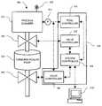
- a process chamber 110is evacuated by a turbomolecular pump 130 .
- Pressure in the process chamber 110is typically measured using one or more capacitance manometer instruments 112 .
- the chamber pressureis controlled by feeding manometer measurements into a tool controller 115 that controls and sequences the overall process.
- the tool controller 115commands a valve controller 125 that drives a stepper motor on a vane or pendulum-type throttle valve 120 placed between the chamber 110 and the turbomolecular pump 130 . Changing the size of the opening of the throttle valve 120 changes the pressure in the chamber 110 .
- a gas flow rateis set by setting a mass flow control 105 to maintain a constant flow rate through the chamber.
- the mass flow controlmaintains a constant mass flow rate as the chamber pressure is adjusted using the throttle valve 120 .
- the term “pumping speed”refers to a volumetric gas flow through the pump. That gas flow may be measured, for example, in standard cubic centimeters per minute (SCCM).
- Throttle valve technologyis usually based on a stepper motor actuator having a fixed number of positions that it can assume.
- a pendulum gate valveis commonly used as a throttle valve in the art.
- the pendulum gate valvehas a pendulum plate that is rotated into and out of sealing position by a servo motor having a finite angular position resolution.
- the valvemay be operated in the 20-80% open range.
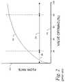
- a graphical view of the flow characteristics of a theoretical gate valveis shown in FIG. 2 , where a plot 230 represents flow rate 210 as a function valve opening percentage 220 . It can be seen that in the 20-80% open range 240 , the plot 230 does not have an excessively small or large slope, permitting stable control.
- the example system shownis optimized for low pressure, high flow steps in a semiconductor processing recipe where the throttle valve operates close to open to maximize conductance but not so open as to limit control stability.
- valveto maintain higher pressures in the chamber, the valve must be operated in the 0-20% open range 260 . In that region, however, a very small change in valve opening yields a very large change in flow rate, causing instability in the pressure control. That limits the ability to control at higher pressures and lower flows when the valve is throttling a large turbomolecular pump with a large diameter inlet port.
- inert gashas been added to the process gas flow to add gas load to the pump. That technique works relatively quickly, and does indeed increase the process chamber pressure without requiring the operation of the throttle valve outside its preferred operating range. The technique, however, significantly increases gas consumption and cost of ownership and may produce unwanted process effects.
- the rotational speed of the turbo pump rotorhas been varied to adjust process chamber pressure. That technique also produces the desired change in effective pumping speed, but requires significant time to decelerate and accelerate the rotor between high pressure and low pressure steps in the processing recipe. The rotational speed change often takes more than 60 seconds, and presents an unacceptable penalty to productivity.
- the backing pump rotational speedhas been varied to change process chamber pressure.
- a backing pumpis commonly used downstream of a primary turbomolecular pump to reduce the exhaust pressure of the primary pump. Changing the rotational speed of the backing pump changes the pressure drop across the primary pump, changing the process chamber pressure. That technique also requires excessive time to change the process chamber pressure. Additionally, it requires that the backing pump be located at an exact and consistent distance from the turbo pump for chamber-to-chamber repeatability.
- the present inventionaddresses the needs described above by providing an apparatus for exhausting gas from an exhaust port of a vacuum chamber to maintain a process pressure in the chamber.
- the apparatusincludes a pressure sensor for measuring pressure in the vacuum chamber, a throttle valve in communication with the exhaust port of the vacuum chamber for regulating flow from the exhaust port, a high-vacuum pump having a pump inlet and a backing port, the pump inlet communicating with the throttle valve, a backing valve in communication with the pump backing port for regulating flow from the backing port, and at least one controller for regulating opening sizes of the throttle valve and the backing valve based on a measurement from the pressure sensor, to maintain the process pressure in the chamber.
- the controllermay include a processor having an input from the pressure sensor for receiving the pressure measurement, and outputs to the backing valve and throttle valve for sending opening size regulation signals.
- the controllermay comprise a tool controller connected to the pressure sensor for sequencing the process chamber through at least one process flow rate and process pressure, a throttle valve controller connected to the throttle valve for controlling an opening of the throttle valve, a backing valve controller connected to the backing valve for controlling an opening of the backing valve, and a processor in communication with the tool controller, the throttle valve controller and the backing valve controller.
- the processorhas storage media for storing computer readable instructions executable by the processor for regulating opening sizes of the throttle valve and the backing valve based on a measurement from the pressure sensor, to maintain the at least one process flow rate and process pressure in the chamber.
- the pressure sensormay be a capacitance manometer.
- the backing valvemay be a butterfly valve, pendulum gate valve or other restricted orifice device.
- the throttle valvemay be a pendulum gate valve.
- the throttle valvemay further include a stepping motor positioning device.
- the throttle valvemay be controllable to a finite number of discrete opening sizes.
- the controlleris further for regulating the opening size of the backing valve to achieve a process pressure in the chamber that is between those process pressures resulting from two adjacent discrete throttle valve opening sizes.
- the process pressure in the chambermay be maintained without changing a rotational speed of the turbomolecular pump.
- Another embodiment of the inventionis method for controlling a process pressure in a vacuum chamber by regulating exhaust gas flowing from an exhaust port of the vacuum chamber and through a turbomolecular pump.
- the methodincludes the steps of reading a pressure in the vacuum chamber, controlling an opening of a throttle valve to regulate flow from the exhaust port to the turbomolecular pump based at least in part on the pressure reading, the throttle valve opening having a preferred operating range, and controlling a backing valve downstream of the turbomolecular pump to maintain the throttle valve opening within the preferred operating range.
- the methodmay also include the step of reading computer executable instructions from a storage media, the instructions being for performing at least a portion of the method.
- the step of reading the pressuremay include reading a signal received from a capacitance manometer.
- the step of controlling the backing valvemay include rotating a butterfly valve.
- the step of controlling the opening of the throttle valvemay include advancing and retracting a pendulum gate valve.
- the step of controlling the opening of the throttle valvemay include actuating a stepping motor positioning device.
- the throttle valvemay be controllable to a finite number of discrete opening sizes, in which case the step of controlling the backing valve comprises regulating the opening size of the backing valve to achieve a process pressure in the chamber that is between those process pressures resulting from two adjacent discrete throttle valve opening sizes.
- the process pressure in the chambermay be controlled without changing a rotational speed of the turbomolecular pump.
- Another embodiment of the inventionis a method for exhausting gas from an exhaust port of a vacuum chamber and through a turbomolecular pump, to maintain a process pressure in the chamber.
- the methodincludes the steps of measuring a pressure in the vacuum chamber, regulating an opening size of a throttle valve in communication between the exhaust port of the vacuum chamber and the turbomolecular pump, and regulating an opening size of a backing valve in communication with a backing port of the pump for regulating a compression ratio of the pump.
- the opening sizes of the throttle valve and the backing valvemaintain the process pressure in the chamber.
- the throttle valvemay be controllable to a finite number of discrete opening sizes, in which case the step of regulating the backing valve further comprises regulating the opening size of the backing valve to achieve a process pressure in the chamber that is between those process pressures resulting from two adjacent discrete throttle valve opening sizes.
- FIG. 1is a schematic diagram showing the functional elements of a prior art vacuum exhaust apparatus.
- FIG. 2is a graph of valve opening versus flow rate for a theoretical gate valve.
- FIG. 3is a schematic diagram showing the functional elements of a vacuum exhaust apparatus according to the present invention.
- FIG. 4is a block diagram showing a method according to one embodiment of the invention.
- FIG. 5is a block diagram showing a method according to another embodiment of the invention.
- the present inventionis a system and method for dynamically adjusting the effective pumping speed of a large turbomolecular pump that is used in combination with a throttling gate valve between the turbo pump and a process chamber.
- the system and methodallow a wide range of stable pressure control.
- the inventionutilizes the compression properties of turbomolecular pumps to dynamically adjust the pumping speed at the inlet port of the pump.
- the compression ratio of a turbo pumpis usually such that as the backing pressure changes, the inlet pressure remains constant. However, above a certain backing pressure (that is determined by the turbo pump rotor design) a change in the backing pressure will result in a change in the inlet pressure.
- FIG. 3An exemplary embodiment 300 of the system of the invention is shown in FIG. 3 .
- a process gasis introduced through a mass flow control 305 into a process gas chamber 310 .
- a throttle valve 320is provided between the process chamber 310 and a turbomolecular pump 330 .
- the throttle valve 320may, for example, be a Series 65.0 pendulum pressure control valve with integrated controller, manufactured by VAT Vakuumventile AG of Haag, Switzerland.
- VAT Vakuumventile AGof Haag, Switzerland.
- One skilled in the artwill recognize that other types of throttle valves, such as traditional gate valves, may be used.
- valve controller 325The valve is controlled by a valve controller 325 . While the controller 325 of FIG. 3 is shown separately from the valve 320 , the controller 325 may instead be integrated with the valve 320 in a single, compact package.
- the throttle valve 320may utilize a stepping motor for positioning the pendulum plate, as discussed above.
- a standard throttle valve with a stepping servo motor positioning devicemay be used, without the disadvantages caused by the positioning resolution near the extremes of travel of the valve.
- the backing valve 340may be a low-cost, coarse resolution butterfly valve.
- the backing valveis a type 153 exhaust throttle valve manufactured by MKS Instruments, Inc. of Wilmington, Mass.
- MKS Instruments, Inc.of Wilmington, Mass.
- control valvesmay be used as the backing valve of the invention.
- a controller 345controls positioning of the backing valve 340 . That controller may be stand-alone or integral.
- the positioning servo for the backing valveneed not be a stepping motor as is used in the throttle valve, but may instead be a lower-cost, coarser positioning device.
- a tool controller 315is connected to receive a signal from the pressure transducer 312 , which may be a capacitance manometer. The tool controller further coordinates the process steps to be completed in the process chamber.
- a system controller 350may be an embedded PC running system control software such as a cut-down version of CPC control software available from ASC Process Systems of Sylmar, Calif.
- the system controller 350is connected for receiving information from the tool controller 315 including the actual and desired process chamber pressures.
- the system controlleris also connected to the throttle valve controller 325 and the backing valve controller 345 , and instructs those controllers to open or close their respective valves according to pressure control algorithms stored in the system controller, which interpret signals from the tool controller 315 .
- the tool controller 315 , valve controller 325 , system controller 350 and valve controller 345comprise an overall controller 360 for regulating opening sizes of the throttle valve and the backing valve based on a measurement from the pressure sensor. While the individual controllers are shown separately in FIG. 3 , it should be noted that any two or more of those controllers may be integrated into a single controller for controlling the system of the invention.
- a diagnostic workstation 370may be provided to program the controller elements of the system, and to change those programs to implement new process recipes, etc.
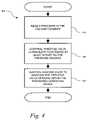
- a method 400 for controlling a process pressure in a vacuum chamber according to the inventionis shown in FIG. 4 .
- the pressureis controlled by regulating exhaust gas flowing from an exhaust port of the vacuum chamber and through a turbomolecular pump.
- a pressureis read (step 420 ) in the vacuum chamber.
- an opening of a throttle valveis controlled (step 430 ) to regulate flow from the exhaust port to the turbomolecular pump.
- the controlis based at least in part on the pressure reading.
- the throttle valve openinghas a preferred operating range.
- a backing valve downstream of the turbomolecular pumpis controlled (Step 440 ) to maintain the throttle valve opening within the preferred operating range.
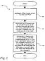
- FIG. 5Another embodiment 500 of the method of the invention is shown in FIG. 5 .
- That methodis for exhausting gas from an exhaust port of a vacuum chamber and through a turbomolecular pump, to maintain a process flow rate and a process pressure in the chamber.
- the methodbegins by measuring (step 520 ) a pressure in the vacuum chamber.
- An opening size of a throttle valve in communication between the exhaust port of the vacuum chamber and the turbomolecular pumpis regulated (step 530 ).
- An opening size of a backing valve in communication with a backing port of the pump for regulating a compression ratio of the pumpis also regulated (step 540 ). Regulating the opening sizes of the throttle valve and the backing valve maintain the process pressure in the chamber.
Landscapes
- Engineering & Computer Science (AREA)
- Chemical & Material Sciences (AREA)
- Mechanical Engineering (AREA)
- General Engineering & Computer Science (AREA)
- Organic Chemistry (AREA)
- Metallurgy (AREA)
- Materials Engineering (AREA)
- Chemical Kinetics & Catalysis (AREA)
- General Chemical & Material Sciences (AREA)
- General Physics & Mathematics (AREA)
- Condensed Matter Physics & Semiconductors (AREA)
- Manufacturing & Machinery (AREA)
- Power Engineering (AREA)
- Microelectronics & Electronic Packaging (AREA)
- Computer Hardware Design (AREA)
- Physics & Mathematics (AREA)
- Drying Of Semiconductors (AREA)
- Non-Positive Displacement Air Blowers (AREA)
- Chemical Vapour Deposition (AREA)
- Compressors, Vaccum Pumps And Other Relevant Systems (AREA)
Abstract
Description
Claims (4)
Priority Applications (7)
| Application Number | Priority Date | Filing Date | Title |
|---|---|---|---|
| US11/245,797US7438534B2 (en) | 2005-10-07 | 2005-10-07 | Wide range pressure control using turbo pump |
| JP2008534596AJP5455371B2 (en) | 2005-10-07 | 2006-09-29 | Wide range pressure control using turbo pump |
| PCT/US2006/038448WO2007044298A2 (en) | 2005-10-07 | 2006-09-29 | Wide range pressure control using turbo pump |
| CN2006800371772ACN101282836B (en) | 2005-10-07 | 2006-09-29 | Wide range pressure control using turbo pump |
| EP06816029.0AEP1934043B1 (en) | 2005-10-07 | 2006-09-29 | Wide range pressure control using turbo pump |
| TW095137039ATW200730731A (en) | 2005-10-07 | 2006-10-05 | Wide range pressure control using turbo pump |
| KR1020087008286AKR101342309B1 (en) | 2005-10-07 | 2008-04-04 | Gas exhaust device and method, and process pressure control method in vacuum chamber |
Applications Claiming Priority (1)
| Application Number | Priority Date | Filing Date | Title |
|---|---|---|---|
| US11/245,797US7438534B2 (en) | 2005-10-07 | 2005-10-07 | Wide range pressure control using turbo pump |
Publications (2)
| Publication Number | Publication Date |
|---|---|
| US20070079758A1 US20070079758A1 (en) | 2007-04-12 |
| US7438534B2true US7438534B2 (en) | 2008-10-21 |
Family
ID=37910064
Family Applications (1)
| Application Number | Title | Priority Date | Filing Date |
|---|---|---|---|
| US11/245,797Active2026-06-15US7438534B2 (en) | 2005-10-07 | 2005-10-07 | Wide range pressure control using turbo pump |
Country Status (7)
| Country | Link |
|---|---|
| US (1) | US7438534B2 (en) |
| EP (1) | EP1934043B1 (en) |
| JP (1) | JP5455371B2 (en) |
| KR (1) | KR101342309B1 (en) |
| CN (1) | CN101282836B (en) |
| TW (1) | TW200730731A (en) |
| WO (1) | WO2007044298A2 (en) |
Cited By (2)
| Publication number | Priority date | Publication date | Assignee | Title |
|---|---|---|---|---|
| US20110200450A1 (en)* | 2010-02-16 | 2011-08-18 | Edwards Limited | Apparatus and method for tuning pump speed |
| US20140083544A1 (en)* | 2012-09-21 | 2014-03-27 | Brian Chan | Manifolds and methods and systems using them |
Families Citing this family (107)
| Publication number | Priority date | Publication date | Assignee | Title |
|---|---|---|---|---|
| WO2007109082A2 (en) | 2006-03-16 | 2007-09-27 | Applied Materials, Inc. | Methods and apparatus for improving operation of an electronic device manufacturing system |
| JP2008072030A (en)* | 2006-09-15 | 2008-03-27 | Matsushita Electric Ind Co Ltd | Plasma processing apparatus, abnormality detection method of plasma processing apparatus, and plasma processing method |
| KR101560705B1 (en)* | 2007-05-25 | 2015-10-16 | 어플라이드 머티어리얼스, 인코포레이티드 | Methods and apparatus for assembling and operating electronic device manufacturing systems |
| CN101678407A (en)* | 2007-05-25 | 2010-03-24 | 应用材料股份有限公司 | Method and apparatus for efficient operation of an abatement system |
| WO2008156687A1 (en)* | 2007-06-15 | 2008-12-24 | Applied Materials, Inc. | Methods and systems for designing and validating operation of abatement systems |
| WO2009055750A1 (en)* | 2007-10-26 | 2009-04-30 | Applied Materials, Inc. | Methods and apparatus for smart abatement using an improved fuel circuit |
| US20090301579A1 (en)* | 2008-06-10 | 2009-12-10 | Gnb Corporation | Vacuum pressure systems with vacuum chamber full-range, closed-loop pressure control |
| US9416448B2 (en)* | 2008-08-29 | 2016-08-16 | Tokyo Electron Limited | Film deposition apparatus, substrate processing apparatus, film deposition method, and computer-readable storage medium for film deposition method |
| KR101014651B1 (en)* | 2010-08-06 | 2011-02-16 | 이철규 | Apparatus and method for generating interlock signal for gate valve connected to master controller of semiconductor manufacturing process equipment |
| US10283321B2 (en) | 2011-01-18 | 2019-05-07 | Applied Materials, Inc. | Semiconductor processing system and methods using capacitively coupled plasma |
| JP5337185B2 (en)* | 2011-03-11 | 2013-11-06 | 株式会社東芝 | Pressure control device |
| US9064815B2 (en) | 2011-03-14 | 2015-06-23 | Applied Materials, Inc. | Methods for etch of metal and metal-oxide films |
| US20130025786A1 (en)* | 2011-07-28 | 2013-01-31 | Vladislav Davidkovich | Systems for and methods of controlling time-multiplexed deep reactive-ion etching processes |
| US20130118609A1 (en)* | 2011-11-12 | 2013-05-16 | Thomas Neil Horsky | Gas flow device |
| US9267739B2 (en) | 2012-07-18 | 2016-02-23 | Applied Materials, Inc. | Pedestal with multi-zone temperature control and multiple purge capabilities |
| US9373517B2 (en) | 2012-08-02 | 2016-06-21 | Applied Materials, Inc. | Semiconductor processing with DC assisted RF power for improved control |
| KR101414159B1 (en)* | 2012-08-14 | 2014-07-01 | 한국표준과학연구원 | Compact mechanical gas compression device, compression method, analysis system with the compression device and analysis method |
| US9132436B2 (en) | 2012-09-21 | 2015-09-15 | Applied Materials, Inc. | Chemical control features in wafer process equipment |
| US10256079B2 (en) | 2013-02-08 | 2019-04-09 | Applied Materials, Inc. | Semiconductor processing systems having multiple plasma configurations |
| CN103728996B (en)* | 2013-12-25 | 2016-06-15 | 合肥京东方光电科技有限公司 | Pressure controller and opening degree control method thereof |
| US9309598B2 (en) | 2014-05-28 | 2016-04-12 | Applied Materials, Inc. | Oxide and metal removal |
| CN104373158B (en)* | 2014-05-30 | 2017-01-04 | 门冉 | The control method of the Steam Turbine that a kind of boiler drives |
| US9966240B2 (en) | 2014-10-14 | 2018-05-08 | Applied Materials, Inc. | Systems and methods for internal surface conditioning assessment in plasma processing equipment |
| US9355922B2 (en) | 2014-10-14 | 2016-05-31 | Applied Materials, Inc. | Systems and methods for internal surface conditioning in plasma processing equipment |
| US11637002B2 (en) | 2014-11-26 | 2023-04-25 | Applied Materials, Inc. | Methods and systems to enhance process uniformity |
| US10573496B2 (en) | 2014-12-09 | 2020-02-25 | Applied Materials, Inc. | Direct outlet toroidal plasma source |
| US10224210B2 (en) | 2014-12-09 | 2019-03-05 | Applied Materials, Inc. | Plasma processing system with direct outlet toroidal plasma source |
| US11257693B2 (en) | 2015-01-09 | 2022-02-22 | Applied Materials, Inc. | Methods and systems to improve pedestal temperature control |
| US20160225652A1 (en) | 2015-02-03 | 2016-08-04 | Applied Materials, Inc. | Low temperature chuck for plasma processing systems |
| US9728437B2 (en) | 2015-02-03 | 2017-08-08 | Applied Materials, Inc. | High temperature chuck for plasma processing systems |
| US9741593B2 (en) | 2015-08-06 | 2017-08-22 | Applied Materials, Inc. | Thermal management systems and methods for wafer processing systems |
| US9691645B2 (en) | 2015-08-06 | 2017-06-27 | Applied Materials, Inc. | Bolted wafer chuck thermal management systems and methods for wafer processing systems |
| US9349605B1 (en) | 2015-08-07 | 2016-05-24 | Applied Materials, Inc. | Oxide etch selectivity systems and methods |
| US10504700B2 (en) | 2015-08-27 | 2019-12-10 | Applied Materials, Inc. | Plasma etching systems and methods with secondary plasma injection |
| US10522371B2 (en) | 2016-05-19 | 2019-12-31 | Applied Materials, Inc. | Systems and methods for improved semiconductor etching and component protection |
| US10504754B2 (en) | 2016-05-19 | 2019-12-10 | Applied Materials, Inc. | Systems and methods for improved semiconductor etching and component protection |
| US9865484B1 (en) | 2016-06-29 | 2018-01-09 | Applied Materials, Inc. | Selective etch using material modification and RF pulsing |
| US10629473B2 (en) | 2016-09-09 | 2020-04-21 | Applied Materials, Inc. | Footing removal for nitride spacer |
| US10062575B2 (en) | 2016-09-09 | 2018-08-28 | Applied Materials, Inc. | Poly directional etch by oxidation |
| US10546729B2 (en) | 2016-10-04 | 2020-01-28 | Applied Materials, Inc. | Dual-channel showerhead with improved profile |
| US10062585B2 (en) | 2016-10-04 | 2018-08-28 | Applied Materials, Inc. | Oxygen compatible plasma source |
| US9934942B1 (en) | 2016-10-04 | 2018-04-03 | Applied Materials, Inc. | Chamber with flow-through source |
| US10062579B2 (en) | 2016-10-07 | 2018-08-28 | Applied Materials, Inc. | Selective SiN lateral recess |
| US9947549B1 (en) | 2016-10-10 | 2018-04-17 | Applied Materials, Inc. | Cobalt-containing material removal |
| DE102016220107B4 (en)* | 2016-10-14 | 2020-01-02 | Fraunhofer-Gesellschaft zur Förderung der angewandten Forschung e.V. | degassing |
| US10163696B2 (en) | 2016-11-11 | 2018-12-25 | Applied Materials, Inc. | Selective cobalt removal for bottom up gapfill |
| US9768034B1 (en) | 2016-11-11 | 2017-09-19 | Applied Materials, Inc. | Removal methods for high aspect ratio structures |
| US10242908B2 (en) | 2016-11-14 | 2019-03-26 | Applied Materials, Inc. | Airgap formation with damage-free copper |
| US10026621B2 (en) | 2016-11-14 | 2018-07-17 | Applied Materials, Inc. | SiN spacer profile patterning |
| JP6996289B2 (en)* | 2016-12-26 | 2022-01-17 | 株式会社島津製作所 | Valve device |
| US10566206B2 (en) | 2016-12-27 | 2020-02-18 | Applied Materials, Inc. | Systems and methods for anisotropic material breakthrough |
| US10431429B2 (en) | 2017-02-03 | 2019-10-01 | Applied Materials, Inc. | Systems and methods for radial and azimuthal control of plasma uniformity |
| US10403507B2 (en) | 2017-02-03 | 2019-09-03 | Applied Materials, Inc. | Shaped etch profile with oxidation |
| US10043684B1 (en) | 2017-02-06 | 2018-08-07 | Applied Materials, Inc. | Self-limiting atomic thermal etching systems and methods |
| US10319739B2 (en) | 2017-02-08 | 2019-06-11 | Applied Materials, Inc. | Accommodating imperfectly aligned memory holes |
| US10943834B2 (en) | 2017-03-13 | 2021-03-09 | Applied Materials, Inc. | Replacement contact process |
| US10319649B2 (en) | 2017-04-11 | 2019-06-11 | Applied Materials, Inc. | Optical emission spectroscopy (OES) for remote plasma monitoring |
| US11276590B2 (en) | 2017-05-17 | 2022-03-15 | Applied Materials, Inc. | Multi-zone semiconductor substrate supports |
| JP7176860B6 (en) | 2017-05-17 | 2022-12-16 | アプライド マテリアルズ インコーポレイテッド | Semiconductor processing chamber to improve precursor flow |
| US11276559B2 (en) | 2017-05-17 | 2022-03-15 | Applied Materials, Inc. | Semiconductor processing chamber for multiple precursor flow |
| US10497579B2 (en) | 2017-05-31 | 2019-12-03 | Applied Materials, Inc. | Water-free etching methods |
| US10049891B1 (en) | 2017-05-31 | 2018-08-14 | Applied Materials, Inc. | Selective in situ cobalt residue removal |
| US10920320B2 (en) | 2017-06-16 | 2021-02-16 | Applied Materials, Inc. | Plasma health determination in semiconductor substrate processing reactors |
| US10541246B2 (en) | 2017-06-26 | 2020-01-21 | Applied Materials, Inc. | 3D flash memory cells which discourage cross-cell electrical tunneling |
| US10727080B2 (en) | 2017-07-07 | 2020-07-28 | Applied Materials, Inc. | Tantalum-containing material removal |
| US10541184B2 (en) | 2017-07-11 | 2020-01-21 | Applied Materials, Inc. | Optical emission spectroscopic techniques for monitoring etching |
| US10354889B2 (en) | 2017-07-17 | 2019-07-16 | Applied Materials, Inc. | Non-halogen etching of silicon-containing materials |
| US10043674B1 (en) | 2017-08-04 | 2018-08-07 | Applied Materials, Inc. | Germanium etching systems and methods |
| US10170336B1 (en) | 2017-08-04 | 2019-01-01 | Applied Materials, Inc. | Methods for anisotropic control of selective silicon removal |
| US10297458B2 (en) | 2017-08-07 | 2019-05-21 | Applied Materials, Inc. | Process window widening using coated parts in plasma etch processes |
| US10283324B1 (en) | 2017-10-24 | 2019-05-07 | Applied Materials, Inc. | Oxygen treatment for nitride etching |
| US10128086B1 (en) | 2017-10-24 | 2018-11-13 | Applied Materials, Inc. | Silicon pretreatment for nitride removal |
| US10256112B1 (en) | 2017-12-08 | 2019-04-09 | Applied Materials, Inc. | Selective tungsten removal |
| US10903054B2 (en) | 2017-12-19 | 2021-01-26 | Applied Materials, Inc. | Multi-zone gas distribution systems and methods |
| US11328909B2 (en) | 2017-12-22 | 2022-05-10 | Applied Materials, Inc. | Chamber conditioning and removal processes |
| US10854426B2 (en) | 2018-01-08 | 2020-12-01 | Applied Materials, Inc. | Metal recess for semiconductor structures |
| US10679870B2 (en) | 2018-02-15 | 2020-06-09 | Applied Materials, Inc. | Semiconductor processing chamber multistage mixing apparatus |
| US10964512B2 (en) | 2018-02-15 | 2021-03-30 | Applied Materials, Inc. | Semiconductor processing chamber multistage mixing apparatus and methods |
| TWI766433B (en) | 2018-02-28 | 2022-06-01 | 美商應用材料股份有限公司 | Systems and methods to form airgaps |
| US10593560B2 (en) | 2018-03-01 | 2020-03-17 | Applied Materials, Inc. | Magnetic induction plasma source for semiconductor processes and equipment |
| US10319600B1 (en) | 2018-03-12 | 2019-06-11 | Applied Materials, Inc. | Thermal silicon etch |
| US10497573B2 (en) | 2018-03-13 | 2019-12-03 | Applied Materials, Inc. | Selective atomic layer etching of semiconductor materials |
| WO2019176031A1 (en)* | 2018-03-14 | 2019-09-19 | 株式会社Kokusai Electric | Substrate treatment device, production method for semiconductor device, and program |
| US10573527B2 (en) | 2018-04-06 | 2020-02-25 | Applied Materials, Inc. | Gas-phase selective etching systems and methods |
| US10490406B2 (en) | 2018-04-10 | 2019-11-26 | Appled Materials, Inc. | Systems and methods for material breakthrough |
| US10699879B2 (en) | 2018-04-17 | 2020-06-30 | Applied Materials, Inc. | Two piece electrode assembly with gap for plasma control |
| US10886137B2 (en) | 2018-04-30 | 2021-01-05 | Applied Materials, Inc. | Selective nitride removal |
| US10755941B2 (en) | 2018-07-06 | 2020-08-25 | Applied Materials, Inc. | Self-limiting selective etching systems and methods |
| US10872778B2 (en) | 2018-07-06 | 2020-12-22 | Applied Materials, Inc. | Systems and methods utilizing solid-phase etchants |
| US10672642B2 (en) | 2018-07-24 | 2020-06-02 | Applied Materials, Inc. | Systems and methods for pedestal configuration |
| KR101990995B1 (en)* | 2018-07-27 | 2019-09-30 | 이형섭 | Apparatus for pressure stabilization of vacuum chamber |
| US10892198B2 (en) | 2018-09-14 | 2021-01-12 | Applied Materials, Inc. | Systems and methods for improved performance in semiconductor processing |
| US11049755B2 (en) | 2018-09-14 | 2021-06-29 | Applied Materials, Inc. | Semiconductor substrate supports with embedded RF shield |
| US11062887B2 (en) | 2018-09-17 | 2021-07-13 | Applied Materials, Inc. | High temperature RF heater pedestals |
| US11417534B2 (en) | 2018-09-21 | 2022-08-16 | Applied Materials, Inc. | Selective material removal |
| US11682560B2 (en) | 2018-10-11 | 2023-06-20 | Applied Materials, Inc. | Systems and methods for hafnium-containing film removal |
| US11121002B2 (en) | 2018-10-24 | 2021-09-14 | Applied Materials, Inc. | Systems and methods for etching metals and metal derivatives |
| US11437242B2 (en) | 2018-11-27 | 2022-09-06 | Applied Materials, Inc. | Selective removal of silicon-containing materials |
| US11721527B2 (en) | 2019-01-07 | 2023-08-08 | Applied Materials, Inc. | Processing chamber mixing systems |
| US10920319B2 (en) | 2019-01-11 | 2021-02-16 | Applied Materials, Inc. | Ceramic showerheads with conductive electrodes |
| US10988843B2 (en)* | 2019-07-30 | 2021-04-27 | Applied Materials, Inc. | System for determining cleaning process endpoint |
| GB2606392B (en)* | 2021-05-07 | 2024-02-14 | Edwards Ltd | A fluid routing for a vacuum pumping system |
| KR20230140546A (en)* | 2022-03-23 | 2023-10-06 | 주식회사 히타치하이테크 | Diagnostic device, semiconductor manufacturing device system, semiconductor device manufacturing system and diagnostic method |
| WO2025024020A1 (en)* | 2023-07-27 | 2025-01-30 | Applied Materials, Inc. | Combined reduced pressure -high vacuum processing chamber |
| DE102023122643A1 (en)* | 2023-08-23 | 2025-02-27 | Vat Holding Ag | Method for determining a correction value for a control device for a control valve |
| US20250102479A1 (en)* | 2023-09-22 | 2025-03-27 | Thermo Finnigan Llc | Method of utilizing deuterium gas for chromatography applications, deuterium gas generator and devices for conservation thereof |
| CN117869335B (en)* | 2023-12-28 | 2025-01-24 | 北京中科科仪股份有限公司 | Automatic pressure-stabilizing molecular pump and control method thereof |
Citations (6)
| Publication number | Priority date | Publication date | Assignee | Title |
|---|---|---|---|---|
| US5443368A (en) | 1993-07-16 | 1995-08-22 | Helix Technology Corporation | Turbomolecular pump with valves and integrated electronic controls |
| US6200107B1 (en)* | 1997-08-15 | 2001-03-13 | The Boc Group Plc | Vacuum pumping systems |
| US20010032613A1 (en)* | 1999-12-03 | 2001-10-25 | Masahiro Arai | Coordinated valve timing and throttle control for controlling intake air |
| US6598615B1 (en) | 2000-11-07 | 2003-07-29 | Applied Materials, Inc. | Compact independent pressure control and vacuum isolation for a turbomolecular pumped plasma reaction chamber |
| US6869880B2 (en)* | 2002-01-24 | 2005-03-22 | Applied Materials, Inc. | In situ application of etch back for improved deposition into high-aspect-ratio features |
| US7140847B2 (en)* | 2004-08-11 | 2006-11-28 | The Boc Group, Inc. | Integrated high vacuum pumping system |
Family Cites Families (6)
| Publication number | Priority date | Publication date | Assignee | Title |
|---|---|---|---|---|
| JPH03107599A (en)* | 1989-09-20 | 1991-05-07 | Ntn Corp | Control system of axial-flow pump device |
| JP3158612B2 (en)* | 1992-03-24 | 2001-04-23 | 株式会社日立製作所 | Dry etching method |
| JPH0633231A (en)* | 1992-07-20 | 1994-02-08 | Hitachi Sci Syst:Kk | Ion sputtering device |
| JP3926977B2 (en)* | 2000-09-21 | 2007-06-06 | 株式会社東芝 | Semiconductor manufacturing method |
| US7278831B2 (en)* | 2003-12-31 | 2007-10-09 | The Boc Group, Inc. | Apparatus and method for control, pumping and abatement for vacuum process chambers |
| FR2878913B1 (en)* | 2004-12-03 | 2007-01-19 | Cit Alcatel | CONTROL OF PARTIAL GAS PRESSURES FOR PROCESS OPTIMIZATION |
- 2005
- 2005-10-07USUS11/245,797patent/US7438534B2/enactiveActive
- 2006
- 2006-09-29CNCN2006800371772Apatent/CN101282836B/ennot_activeExpired - Fee Related
- 2006-09-29EPEP06816029.0Apatent/EP1934043B1/enactiveActive
- 2006-09-29JPJP2008534596Apatent/JP5455371B2/ennot_activeExpired - Fee Related
- 2006-09-29WOPCT/US2006/038448patent/WO2007044298A2/enactiveApplication Filing
- 2006-10-05TWTW095137039Apatent/TW200730731A/enunknown
- 2008
- 2008-04-04KRKR1020087008286Apatent/KR101342309B1/ennot_activeExpired - Fee Related
Patent Citations (6)
| Publication number | Priority date | Publication date | Assignee | Title |
|---|---|---|---|---|
| US5443368A (en) | 1993-07-16 | 1995-08-22 | Helix Technology Corporation | Turbomolecular pump with valves and integrated electronic controls |
| US6200107B1 (en)* | 1997-08-15 | 2001-03-13 | The Boc Group Plc | Vacuum pumping systems |
| US20010032613A1 (en)* | 1999-12-03 | 2001-10-25 | Masahiro Arai | Coordinated valve timing and throttle control for controlling intake air |
| US6598615B1 (en) | 2000-11-07 | 2003-07-29 | Applied Materials, Inc. | Compact independent pressure control and vacuum isolation for a turbomolecular pumped plasma reaction chamber |
| US6869880B2 (en)* | 2002-01-24 | 2005-03-22 | Applied Materials, Inc. | In situ application of etch back for improved deposition into high-aspect-ratio features |
| US7140847B2 (en)* | 2004-08-11 | 2006-11-28 | The Boc Group, Inc. | Integrated high vacuum pumping system |
Non-Patent Citations (3)
| Title |
|---|
| PCT International Search Report of International Application No. PCT/US06/38448; Date of mailing of the International Search Report: Nov. 26, 2007. |
| PCT Notification of Transmittal of the International Search Report and the Written Opinion of the International Searching Authority, or the Declaration of International Application No. PCT/US06/38448; Date of mailing: Nov. 26, 2007. |
| PCT Written Opinion of the International Searching Authority of International Application No. PCT/US06/38448; Date of mailing: Nov. 26, 2007. |
Cited By (4)
| Publication number | Priority date | Publication date | Assignee | Title |
|---|---|---|---|---|
| US20110200450A1 (en)* | 2010-02-16 | 2011-08-18 | Edwards Limited | Apparatus and method for tuning pump speed |
| US8657584B2 (en) | 2010-02-16 | 2014-02-25 | Edwards Limited | Apparatus and method for tuning pump speed |
| US20140083544A1 (en)* | 2012-09-21 | 2014-03-27 | Brian Chan | Manifolds and methods and systems using them |
| US10691143B2 (en) | 2012-09-21 | 2020-06-23 | Perkinelmer Health Sciences, Inc. | Manifolds and methods and systems using them |
Also Published As
| Publication number | Publication date |
|---|---|
| CN101282836B (en) | 2012-09-05 |
| WO2007044298A3 (en) | 2008-01-31 |
| CN101282836A (en) | 2008-10-08 |
| TW200730731A (en) | 2007-08-16 |
| EP1934043A4 (en) | 2012-04-18 |
| JP2009511248A (en) | 2009-03-19 |
| JP5455371B2 (en) | 2014-03-26 |
| EP1934043B1 (en) | 2014-11-19 |
| US20070079758A1 (en) | 2007-04-12 |
| WO2007044298A2 (en) | 2007-04-19 |
| KR101342309B1 (en) | 2013-12-16 |
| KR20080056193A (en) | 2008-06-20 |
| EP1934043A2 (en) | 2008-06-25 |
Similar Documents
| Publication | Publication Date | Title |
|---|---|---|
| US7438534B2 (en) | Wide range pressure control using turbo pump | |
| JP4382984B2 (en) | Pressure control method and apparatus in vacuum processing apparatus | |
| US7253107B2 (en) | Pressure control system | |
| US20030209322A1 (en) | Methods and apparatus for maintaining a pressure within an environmentally controlled chamber | |
| US6478923B1 (en) | Vacuum operation apparatus | |
| CN101631890B (en) | Apparatus for gas handling in vacuum processes | |
| JP4417434B2 (en) | Method and apparatus for controlling the pressure of a vacuum processor | |
| CN112695297B (en) | Method for controlling chamber pressure in semiconductor process | |
| CN114415747B (en) | Pressure regulating method of vacuum regulating valve | |
| JP5004614B2 (en) | Vacuum processing equipment | |
| US12228951B2 (en) | Vacuum exhaust system | |
| CN118815690A (en) | Pumps and ventilation systems for vacuum processes | |
| US6711956B2 (en) | Method and apparatus for regulating exhaust pressure in evacuation system of semiconductor process chamber | |
| JPS6317520A (en) | Pressure controller for chemical vapor growth device | |
| US12442074B2 (en) | System and method for controlling foreline pressure | |
| US20250320602A1 (en) | System and method for controlling foreline pressure | |
| US20240068093A1 (en) | System and method for controlling foreline pressure | |
| JP2003229417A (en) | Vacuum processing apparatus and method of controlling the same | |
| US7181306B2 (en) | Enhanced plasma etch process | |
| KR100467539B1 (en) | Method and apparatus for pressure control in vacuum processors | |
| JP2663914B2 (en) | Vacuum processing equipment for semiconductor manufacturing | |
| KR19980035268A (en) | Vacuum device for semiconductor process chamber and its management method | |
| JPH0250421A (en) | Gas feeder | |
| JP2004071740A (en) | Plasma processing equipment | |
| JPH04316319A (en) | semiconductor manufacturing equipment |
Legal Events
| Date | Code | Title | Description |
|---|---|---|---|
| AS | Assignment | Owner name:BOC GROUP, INC., THE, NEW JERSEY Free format text:ASSIGNMENT OF ASSIGNORS INTEREST;ASSIGNORS:HOLLAND, PETER JOHN;WILSON, KATE;STEPHENSON, DAWN;REEL/FRAME:017075/0857 Effective date:20051004 | |
| AS | Assignment | Owner name:BOC EDWARDS, INC., MASSACHUSETTS Free format text:ASSIGNMENT OF ASSIGNORS INTEREST;ASSIGNOR:THE BOC GROUP, INC.;REEL/FRAME:019767/0251 Effective date:20070330 Owner name:BOC EDWARDS, INC.,MASSACHUSETTS Free format text:ASSIGNMENT OF ASSIGNORS INTEREST;ASSIGNOR:THE BOC GROUP, INC.;REEL/FRAME:019767/0251 Effective date:20070330 | |
| AS | Assignment | Owner name:EDWARDS VACUUM, INC., MASSACHUSETTS Free format text:CHANGE OF NAME;ASSIGNOR:BOC EDWARDS, INC.;REEL/FRAME:020654/0963 Effective date:20070920 Owner name:EDWARDS VACUUM, INC.,MASSACHUSETTS Free format text:CHANGE OF NAME;ASSIGNOR:BOC EDWARDS, INC.;REEL/FRAME:020654/0963 Effective date:20070920 | |
| STCF | Information on status: patent grant | Free format text:PATENTED CASE | |
| FPAY | Fee payment | Year of fee payment:4 | |
| AS | Assignment | Owner name:EDWARDS VACUUM LLC, NEW YORK Free format text:CHANGE OF NAME;ASSIGNOR:EDWARDS VACUUM, INC.;REEL/FRAME:036922/0581 Effective date:20141211 | |
| FPAY | Fee payment | Year of fee payment:8 | |
| MAFP | Maintenance fee payment | Free format text:PAYMENT OF MAINTENANCE FEE, 12TH YEAR, LARGE ENTITY (ORIGINAL EVENT CODE: M1553); ENTITY STATUS OF PATENT OWNER: LARGE ENTITY Year of fee payment:12 |