US7438186B2 - Modular product display system - Google Patents
Modular product display systemDownload PDFInfo
- Publication number
- US7438186B2 US7438186B2US11/354,862US35486206AUS7438186B2US 7438186 B2US7438186 B2US 7438186B2US 35486206 AUS35486206 AUS 35486206AUS 7438186 B2US7438186 B2US 7438186B2
- Authority
- US
- United States
- Prior art keywords
- display
- container
- panel
- containers
- side panel
- Prior art date
- Legal status (The legal status is an assumption and is not a legal conclusion. Google has not performed a legal analysis and makes no representation as to the accuracy of the status listed.)
- Expired - Fee Related, expires
Links
Images


Classifications
- A—HUMAN NECESSITIES
- A47—FURNITURE; DOMESTIC ARTICLES OR APPLIANCES; COFFEE MILLS; SPICE MILLS; SUCTION CLEANERS IN GENERAL
- A47F—SPECIAL FURNITURE, FITTINGS, OR ACCESSORIES FOR SHOPS, STOREHOUSES, BARS, RESTAURANTS OR THE LIKE; PAYING COUNTERS
- A47F5/00—Show stands, hangers, or shelves characterised by their constructional features
- A47F5/0018—Display racks with shelves or receptables
- A47F5/0025—Display racks with shelves or receptables having separate display containers or trays on shelves or on racks
Definitions
- the inventiongenerally relates to product display systems.
- Some product display systemshave multi-compartment displays that are permanently attached to one another to display merchandise in a “column” configuration. Since the compartments of these displays are not designed to be detachable, there may be a limited number of applications in which these displays can be used. For example, these displays may be limited to either floor stand deployment or hanging deployment, but typically not both. These displays are often not suitable for countertop use due to the potential for the displays to tip over or size issues. Furthermore, the number of compartments and, therefore, the amount of merchandise that can be displayed is generally fixed, which may further limit their usefulness.
- While other approaches to displaying merchandisemay make use of individual compartments, a number of difficulties remain.
- one approachis to use compartments that are individually attachable to a floor stand, wherein the attachment mechanism requires multiple intermediate pieces for assembly. Such an approach may require each compartment to have dedicated hanging pieces.
- the displaymay be complicated, time consuming to deploy, and susceptible to lost pieces and/or complicated shipping arrangements.
- the extra parts required for assemblyfurther increase the bill of materials.
- other approaches to individual product display compartmentsmay make use of separate interconnection pieces, leading to similar drawbacks of the display being complicated, time consuming to deploy, susceptible to lost pieces and/or complicated shipping arrangements, and/or increasing the bill of materials.
- Certain embodiments of the inventionprovide for a product display system comprising a plurality of detachable display containers, where each display container in the plurality of detachable display containers includes at least a first side panel, a second side panel, a back panel and a bottom panel.
- the back panelextends between the first side panel and the second side panel
- the bottom panelextends between the first side panel and the second side panel.
- the first side panel, the second side panel, the back panel and the bottom panelare adapted to form an area for holding product to be displayed.
- the display containershave integral means for interconnecting one display container to an adjacent display container.
- a display containermay include one or more container interconnection flaps, wherein each container interconnection flap is integral with one of the panels.
- the display containermay include a first container interconnection flap integral with the first side panel and a second container interconnection flap integral with the second side panel.
- the container interconnection flapsenable the display container to be coupled to an adjacent display container.
- the adjacent display containermay have slots or other apertures formed in or between one or more of its panels for receiving the interconnection flaps, thereby enabling the two display containers to be coupled together.
- the bottom surface of the bottom panelfacilitates placement of the display container on a substantially horizontal surface such as a countertop or shelf.
- the back panelincludes a mounting mechanism that enables the display container to be hung.
- the product display systemcomprises a plurality of detachable display containers as described above in combination with a stand, rack, pole, base and/or tray adapted to hold the plurality of detachable display containers.
- the product display systemmay comprise a plurality of detachable display containers in combination with a floor stand.
- the display containersmay be held by the floor stand in various ways.
- the back panel of each display containermay include a mounting mechanism that enables the display container to be hung from the floor stand.
- each display containermay have a floor stand interconnection flap that fits into a corresponding slot or other aperture in the floor stand.
- each display containermay have a slot or other aperture that receives a flap from the floor stand.
- the floor standhas support panels on which each display container rests. Other ways of mounting the display containers to a floor stand are possible.
- the product display systemmay comprise a plurality of detachable display containers in combination with a tray.
- the traymay be sized to hold a plurality of detachable display containers for display.
- the traymay have a bottom surface that facilitates placement of the product display system (e.g., the tray holding a plurality of display containers) on a substantially horizontal surface such as a countertop or shelf.
- the display containersmay be held by the tray in various ways. For example, the display containers may simply fit inside the tray. Other ways of having the tray hold a plurality of display containers are possible, including ways similar to those described above.
- the inventionmay be practiced as a system wherein same display container may be used either as a standalone container, may be connected to one or more other similar containers, may be mounted either alone or with other connected containers to a floor stand or powerwing rack, or may be placed either alone or with other similar containers in a tray.
- the display containerprovides versatility to the marketer or retailer, as the same display container may be displayed in different ways.
- Each detachable display containermay be constructed of a single sheet of material. That is, for example, the first side panel, second side panel, back panel, bottom panel, and any interconnection flaps of a single detachable display container may all be cut from a single sheet of material.
- the materialmay be cardboard, paperboard, or any other suitable material.
- FIG. 1is a perspective view of an example of a product display system according to an embodiment of the invention
- FIG. 2is an enlarged view of an example of a container interconnection flap and a slot according to an embodiment of the invention
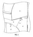
- FIG. 3is an enlarged view of an example of two interconnected display containers according to an embodiment of the invention.
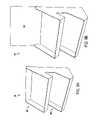
- FIG. 4is a perspective view of an example of a display container according to a second embodiment of the invention.
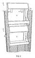
- FIG. 5is a perspective view of an example of two display containers as in FIG. 4 , wherein the display containers are mounted to a rack;
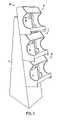
- FIG. 6is a perspective view of an example of three display containers as in FIG. 4 , wherein the display containers are coupled to a floor stand;
- FIG. 7is a perspective view of an example of two display containers as in FIG. 4 , wherein the display containers are disposed within a tray;
- FIGS. 8A-8Fare perspective views of examples of display containers according to a third embodiment of the invention.
- FIGS. 9A-Bare perspective views of an example of a product container according to a fourth embodiment of the invention.
- FIG. 10is a perspective view of an example of two product containers as in FIGS. 9A-B , wherein the product containers are disposed within a tray.
- Certain embodiments of the inventionprovide a modular product display system in which detachable display containers of the system can be used in a wide variety of environments.
- the detachable display containersmay be coupled directly to one another to form an interconnected multi-compartment arrangement that can stand alone, can be hung from a rack, can be attached to a floor stand, can be placed in a tray, and so on.
- the detachable display containersmay also be used individually, with each individual display container in a hanging or floor stand configuration, positioned individually on a counter top or shelf, or disposed side-by-side in a tray for shipping and/or retail use.
- the highly adaptable nature of the modular product display systemtherefore provides a number of advantages over conventional approaches.
- FIG. 1shows a modular product display system 20 having a plurality of detachable display containers 22 ( 22 A- 22 B), wherein each display container 22 includes a plurality of panels that are adapted to form an area for holding product to be displayed.
- each container 22may be used permanently or temporarily in a “point of purchase” (POP) environment to display and/or dispense items such as candy, shoes, tobacco products, batteries, video cassettes, DVDs and so on.
- POPpoint of purchase
- the system 20can include a greater or lesser number of containers 22 than the number shown, depending upon the particular application.
- the lower display container 22 Bwhich is identical to the upper display container 22 A, has a first side panel 24 , a second side panel 25 , a back panel 26 extending between the first side panel 24 and the second side panel 25 , and a bottom panel 27 extending between the first side panel 24 and the second side panel 25 .
- the display container 22 Bcan also have a front panel 46 extending between the first side panel 24 and the second side panel 25 . Any of the panels, including the front panel 46 , may include an advertising message or other indicia (not shown). The advertising message can be related to the merchandise to be dispensed from the display container 22 B.
- the bottom surface of the bottom panel 27can facilitate placement of the display container 22 B on a substantially horizontal surface such as a countertop or shelf.
- each illustrated side panel 24 , 25includes a container interconnection flap 28 , 30 that is integral to the respective side panel.
- the illustrated first side panel 24has a first container interconnection flap 28 that is integral to the first side panel 24
- the second side panel 25has a second container interconnection flap 30 that is integral to the second side panel 25 .
- the use of one or more container interconnection flaps 28 , 30 on each of the containers 22ensures that multiple display containers can be joined together to form a multi-compartment assembly of any desired size.
- the modular product display system 20can have a simplified construction, simplified assembly, reduced bill of materials, and a reduced likelihood of lost pieces during the life cycle of the system 20 .
- the interconnection mechanism between the product display containers of FIG. 1is shown in greater detail in FIGS. 2 and 3 .
- the upper display container 22 Ahas a slot 34 formed between the bottom panel 32 and the side panel 36 , wherein the slot 34 is adapted to receive the interconnection flap 30 of display container 22 B, thereby enabling the display containers 22 A, 22 B to be coupled to one another.
- the interconnection flap 30is assembled fully within the slot 34 , the outer edge of the interconnection flap 30 is “flush” with the outermost edge of the bottom panel 32 .
- the interconnection flap 28may have a similar mating relationship with a slot on the other side of the upper display container 22 A.
- the illustrated interconnection flap 30also has a fold 40 and angled slits 38 to facilitate mating of the interconnection flap 30 with the adjacent upper display container 22 A.
- the fold 40enables the wide portion of the interconnection flap 30 to bend inward with respect to the display container 22 B, and the narrowest area of the side panel 25 between the slits 38 provides a temporary fold line for the interconnection flap 30 to bend and flex outward with respect to the display container 22 B.
- the front crease 44 where the front panel 46 and the side panel 25 intersectcan be given a similar angle with respect to the fold 40 as the front edge 42 of the flap 30 , so that the interconnection flap 30 can be “tucked” behind the front panel 46 if the interconnection flap 30 of the lower display container 22 B is not needed to couple to the lower display container 22 B to an adjacent container.
- the other interconnection flap 28can be true for the other interconnection flap 28 .
- interconnection flaps and slotscan have other configurations. For example, they may be arranged for side-by-side connection as opposed to a stackable connection as illustrated.
- the back panel 26 of the illustrated display container 22 Balso has a mounting mechanism that enables the display container 22 B to be hung.
- the mounting mechanismis one or more apertures 48 that are designed to mate with an appropriate mechanism such as a “powerwing” extension hook.
- the display container 22 Bmay therefore be hung from a substantially vertical structure or surface such as a powerwing rack, pole, mounting strip, etc. Since the upper display container 22 A, which also has a mounting mechanism, can be connected directly to the lower display container 22 B, the two display containers 22 can both be hung together by using the mounting mechanism of only the upper display container 22 A, if desired.
- the container 50has a bottom surface that facilitates placement of the display container 50 on substantially flat surfaces and is made up of the bottom edge of the first side panel 52 and the bottom edge of the second side panel 54 . In this instance, the bottom edges of the side panels 52 , 54 would contact the countertop, shelf, etc., rather than the bottom surface of the bottom panel 56 .
- the display container 50is not shown as having container interconnection flaps such as flaps 28 , 30 ( FIGS. 1-3 ), the display container 50 may be readily modified to include these features.
- FIG. 5shows that the display containers 50 can each include a mounting mechanism that enables the containers 50 to be hung from a rack 58 .
- each illustrated display container 50includes two clips 60 , which extend through the back panel 62 and hook over the individual rails of the rack 58 .
- the clips 60can engage with the rail 64 to hold the upper display container 50 in place.
- the lower display containercan similarly mate with a lower rail of 66 of the rack 58 .
- any number of display containers 50can be used to display and/or dispense merchandise depending upon the size of the rack 58 and the amount of merchandise to be displayed and/or dispensed.
- FIG. 6shows an alternative configuration 68 in which three product display containers 50 are mounted to a substantially vertical floor stand 70 .
- the clips 60 of the display containers 50are inserted through the back panels 62 and into corresponding slots (not shown) in the floor stand 70 .
- the number of display containers 50can vary depend upon the application.
- FIG. 7shows another example in which the display containers 50 are arranged in a tray 72 .
- the tray 72can be used as a “PDQ” display in which the display containers 50 , the tray 72 and the merchandise (not shown) to be displayed and/or dispensed are all shipped in the same standard shipping container (not shown).
- the shipping containercan be simply cut away from the display assembly 74 , wherein the display assembly 74 is then placed in the desired dispensing location.
- the retailerdoes not need to load the merchandise into the display containers 50 or the display containers 50 into the tray 72 . Simply put, no assembly is required for the configuration shown.
- a divider 76can also be disposed between the containers 50 in the tray 72 , where the forward-facing surface 78 or other areas of the divider 76 can be provided with an advertising message or other indicia.
- the tray 72may also carry an advertising message or other indicia.
- the tray 72 and divider 76are dimensioned so that the display containers 50 fit snugly within the tray 72 . That is, the tray has a bottom panel and four sides defining a containment area, and the containment area is equal to the sum of the areas of the divider(s) and display container(s) to be accommodated.
- FIGS. 8A-Fvarious interconnection configurations are shown for an alternative display container 80 .
- Each display container 80 as shown in FIGS. 8A-8Fhas a horizontally hinged access panel 84 to provide access to the merchandise contained therein.
- Each display container 80may include one or more container interconnection flaps 30 ( FIGS. 1-3 ) to facilitate direct interconnection between the display containers 80 .
- Each display container 80may also include apertures 48 ( FIGS. 1-3 ), clips 60 ( FIGS. 5-7 ), or any other suitable mechanism for hanging the display containers 80 , if desired.
- FIG. 8Ashows four display containers 80 being held by a substantially vertical floor stand 82 .
- the display containers 80may be held by the floor stand 82 in various ways.
- the back panel of each display containermay include a mounting mechanism as described above.
- each display container 80may have a flap that fits into a corresponding slot or other aperture in the floor stand 82 , or each display container 80 may have a slot or other aperture that receives a flap from the floor stand 82 .
- the floor stand 82may have support panels on which each display container 80 rests.
- FIG. 8Bshows eight display containers 80 hung from a rack 86 in an alternative configuration.
- the display containers 80can use a variety of mounting mechanisms to couple the containers 80 to the rack 86 .
- FIG. 8Cdemonstrates an “inline” approach in which a display container 80 is mounted to a wall strip 88 via a hook 90 .
- a biasing strip 92can be used to bias the bottom portion of the display container 80 away from the wall 94 so that display container 80 is parallel with the wall 94 .
- the wall 94may also include a horizontal shelf surface 96 to provide additional support for the display container 80 by contacting the bottom surface of the display container 80 .
- FIG. 8Dshows a display container 80 positioned on a substantially horizontal surface such as a shelf or countertop.
- a substantially horizontal surfacesuch as a shelf or countertop.
- the same display container 80 that can be connected to other display containers and/or mounted to a floor stand or rackmay also be used as a standalone display container.
- FIG. 8Eshows eight display containers 80 being disposed within a tray 100 .
- the tray 100could be used as a PDQ display in which the tray 100 , the display containers 80 , and the merchandise (not shown) are all shipped in the same shipping container (not shown) to simplify the merchandise display process.
- two rows of display containers 80are provided in the tray 100 so that as the first row of display containers 80 is emptied, the second row can be moved forward.
- the front panel of the tray 100 , as well as the various outer surfaces of the display containers 80can include advertising messages.
- FIG. 8Fdemonstrates that the display container 80 also be mounted to a retail aisle pole 102 in an alternative configuration.
- the display container 80could be provided with a strap to wrap around the pole, or with adhesive to attach to the pole, etc., to hold the display container 80 in place in a temporary or permanent fashion.
- the modular display container 80can be used in a wide variety of applications.
- the display containerprovides versatility to the marketer or retailer.
- the simplified construction and assemblysaves time and cost.
- FIG. 9Aan alternative product display container 104 is shown.
- the container 104has multiple compartments 106 , and the compartments 106 are slanted downward rather than horizontal.
- the display container 104may be configured to be attached to other display containers 104 (as by flaps and corresponding apertures as described above), either in a side-by-side or stackable configuration.
- FIG. 9Bshows the display container 104 with a header 108 attached to the upper most portion of the display container 104 , where the header 108 can carry larger advertising messages. If stacked with other display containers 104 , the header 108 would ordinarily be on the top display container 104 .
- FIG. 10shows two display containers 104 disposed within a tray 110 , wherein the tray 110 , display containers 104 and merchandise (not shown) can be combined with a shipping container (not shown).
- each display container 104has a hood 112 that is adapted to carry advertising messages.
- Display containerssuch as the illustrated modular display containers 22 ( FIG. 1-FIG . 3 ), modular display containers 52 ( FIG. 4-FIG . 7 ), modular display containers 80 ( FIGS. 8A-8F ), and modular display containers 104 ( FIGS. 9 and 10 ) can be fabricated out of materials such as cardboard, paperboard, or other suitable material, for example by cutting the desired shape from stock material.
- Each modular display containermay be constructed of a single sheet of material. Other materials and techniques are possible, such as manufacturing the containers out of plastic by molding.
- the display containers of the various embodiments of the inventionmay of course take numerous forms other than those in the illustrated examples.
- the display containermay have only one container interconnection flap.
- the container interconnection flapsneed not extend from the side panels; for example, they may extend from the back panel and/or front panel.
- the bottom panels of the display containersmay be provided with slots or other apertures on the front and rear-most portions rather than the side portions in order to mate with the interconnection flaps.
- Many other variationsare possible within the scope of the embodiments of the invention.
- Coupledis used herein to refer to any connection, direct or indirect, and unless otherwise stated may include a mechanical, electrical, optical, electromagnetic, integral, separate, or other relationship between the components in question. Furthermore, any use of terms such as “first” and “second” do not necessarily infer a chronological relationship.
Landscapes
- Display Racks (AREA)
- Cartons (AREA)
Abstract
Description
Claims (13)
Priority Applications (1)
| Application Number | Priority Date | Filing Date | Title |
|---|---|---|---|
| US11/354,862US7438186B2 (en) | 2006-02-16 | 2006-02-16 | Modular product display system |
Applications Claiming Priority (1)
| Application Number | Priority Date | Filing Date | Title |
|---|---|---|---|
| US11/354,862US7438186B2 (en) | 2006-02-16 | 2006-02-16 | Modular product display system |
Publications (2)
| Publication Number | Publication Date |
|---|---|
| US20070187346A1 US20070187346A1 (en) | 2007-08-16 |
| US7438186B2true US7438186B2 (en) | 2008-10-21 |
Family
ID=38367267
Family Applications (1)
| Application Number | Title | Priority Date | Filing Date |
|---|---|---|---|
| US11/354,862Expired - Fee RelatedUS7438186B2 (en) | 2006-02-16 | 2006-02-16 | Modular product display system |
Country Status (1)
| Country | Link |
|---|---|
| US (1) | US7438186B2 (en) |
Cited By (6)
| Publication number | Priority date | Publication date | Assignee | Title |
|---|---|---|---|---|
| US8839964B2 (en) | 2013-01-28 | 2014-09-23 | Target Brands, Inc. | Bow and ribbon display fixture |
| USD716552S1 (en) | 2012-04-26 | 2014-11-04 | Target Brands, Inc. | Bin |
| USD724869S1 (en) | 2013-02-08 | 2015-03-24 | Target Brands, Inc. | Display fixture |
| USD745781S1 (en)* | 2014-03-31 | 2015-12-22 | Seville Classics Inc | Bin |
| USD766574S1 (en)* | 2015-01-21 | 2016-09-20 | L & F Plastics, Co., Ltd. | Container |
| US20220330723A1 (en)* | 2021-04-15 | 2022-10-20 | Liberty Hardware Mfg. Corp. | Product display assembly |
Families Citing this family (12)
| Publication number | Priority date | Publication date | Assignee | Title |
|---|---|---|---|---|
| US20070235396A1 (en)* | 2006-04-10 | 2007-10-11 | Moss Geoffrey A | Tilt back merchandise display stand |
| US7850023B2 (en)* | 2006-05-03 | 2010-12-14 | Cadbury Adams Usa Llc | Modular device for displaying and merchandising retail articles |
| US8297490B2 (en)* | 2008-05-15 | 2012-10-30 | York Container Company | Materials for and method for manufacturing a container with corner supports and the resulting container |
| US8177117B2 (en)* | 2008-05-15 | 2012-05-15 | York Container Company | Materials for and method for manufacturing container with corner supports and resulting container |
| USD609510S1 (en) | 2008-05-27 | 2010-02-09 | Target Brands, Inc. | Shelf assembly |
| US8056740B2 (en)* | 2008-05-27 | 2011-11-15 | Target Brands, Inc. | Product display assembly and tester security apparatus |
| US8087522B2 (en)* | 2008-05-27 | 2012-01-03 | Target Brands, Inc. | Quick secure shelving |
| US7677433B2 (en)* | 2008-06-06 | 2010-03-16 | York Container Company | Materials for and method for manufacturing container and resulting container |
| US20100083618A1 (en)* | 2008-10-08 | 2010-04-08 | York Container Company | Materials for and method for manufacturing container with stacking shoulders and resulting container |
| US7981017B2 (en)* | 2009-03-27 | 2011-07-19 | York Container Company | Materials for and method for manufacturing retail container and resulting retail container |
| US20110011922A1 (en)* | 2009-07-14 | 2011-01-20 | York Container Company | Materials for an method for manufacturing a divided container and resulting divided container |
| USD998994S1 (en)* | 2023-06-01 | 2023-09-19 | Jie Chen | Shelf |
Citations (47)
| Publication number | Priority date | Publication date | Assignee | Title |
|---|---|---|---|---|
| US1225705A (en)* | 1915-05-05 | 1917-05-08 | Edward T Dyson | Shipping-case. |
| US2110934A (en) | 1936-04-17 | 1938-03-15 | Charles L Kanty | Display carton |
| US2131391A (en)* | 1937-01-28 | 1938-09-27 | Schraffenberger Strieder | Display carton |
| US2135533A (en) | 1936-04-22 | 1938-11-08 | Nat Folding Box Co | Display carton |
| US3612288A (en) | 1969-08-27 | 1971-10-12 | James Richard Lesley | Hinged display rack |
| US3777897A (en) | 1971-10-18 | 1973-12-11 | J Gray | Continuous cascade shelving assembly of knockdown character |
| US3918576A (en) | 1974-06-21 | 1975-11-11 | Taub Family Trust U A Sept 1 1 | Combination shipping container and display support |
| US4015886A (en)* | 1975-11-03 | 1977-04-05 | Wickenberg Chester H | Storage bins |
| US4022328A (en) | 1976-04-29 | 1977-05-10 | Bradbar Mfg. Corporation | Folding display rack |
| US4311100A (en) | 1979-10-29 | 1982-01-19 | Container Corporation Of America | Multi-shelf display stand |
| US4385721A (en)* | 1981-09-08 | 1983-05-31 | Container Corporation Of America | Tray corner structure |
| US4488652A (en) | 1983-03-14 | 1984-12-18 | The Mead Corporation | Merchandising display connector means |
| USD276777S (en) | 1981-10-16 | 1984-12-18 | Eldon Industries, Inc. | Magazine holder or the like |
| US4570805A (en) | 1981-10-09 | 1986-02-18 | Irving Smith | Foldable display stand |
| US4705162A (en)* | 1986-11-13 | 1987-11-10 | Kupersmit Julius B | Multiple display carton shipping package |
| US4811837A (en)* | 1987-03-25 | 1989-03-14 | United Brands Company | Produce shipment and separable distribution and display carton |
| US4825624A (en)* | 1987-11-25 | 1989-05-02 | Duracell Inc. | Modular promotional display |
| US4871218A (en) | 1987-10-20 | 1989-10-03 | Swinson Owen I | Collapsible storage and display device |
| USD314091S (en) | 1987-08-24 | 1991-01-29 | Thomson-Leeds Company, Ltd. | Collapsible display and dispenser stand |
| US5039002A (en)* | 1990-05-02 | 1991-08-13 | The Mead Corporation | Article display case |
| US5040688A (en) | 1987-11-09 | 1991-08-20 | Harbor Industries | Foldable display |
| US5115965A (en)* | 1990-06-27 | 1992-05-26 | Frutas Ballester, S.A. | Box for containing spherical bodies |
| US5180058A (en) | 1991-11-25 | 1993-01-19 | Pro Eton Corporation | Expandable disc holder assembly |
| US5255801A (en) | 1990-08-30 | 1993-10-26 | Rga Accessories, Inc. | Free-standing merchandise display |
| US5269408A (en)* | 1993-03-22 | 1993-12-14 | E. S. Originals, Inc. | Hang-up display box for shoes |
| US5322172A (en) | 1993-01-04 | 1994-06-21 | Maglione Stephen T | Collapsible display stand |
| US5513745A (en) | 1994-10-26 | 1996-05-07 | Gibson Greetings, Inc. | Shipment and display fixture for greeting cards |
| US5630518A (en) | 1995-05-04 | 1997-05-20 | Collins; Larry D. | Merchandising display |
| US5826732A (en) | 1996-02-06 | 1998-10-27 | Stone Container Corporation | Collapsible point-of-purchase display apparatus |
| US5899345A (en) | 1997-02-28 | 1999-05-04 | Fuller; Stephen M. | Mixable product display stand |
| US6109582A (en) | 1998-01-31 | 2000-08-29 | Repaci; Louis E. | Product shipping and display strip system |
| US6247593B1 (en)* | 1999-03-17 | 2001-06-19 | Ashland Inc. | Carton having integrally formed alignment retainer tabs |
| US6427853B2 (en) | 1998-06-19 | 2002-08-06 | American Greetings Corporation | Retail product display system |
| US20030173318A1 (en) | 2002-03-18 | 2003-09-18 | Tom Rushing | Merchandise shipping and display system |
| US20040040921A1 (en) | 2002-08-29 | 2004-03-04 | Chandaria Ashok Velji | Display card for merchandising strips and method of manufacturing same |
| US6712227B2 (en) | 2002-02-12 | 2004-03-30 | Menasha Corporation | Foldable merchandising strip |
| US6715623B2 (en) | 2002-02-26 | 2004-04-06 | Stone Container Corporation | Collapsible display shelving |
| USD493289S1 (en) | 2002-08-20 | 2004-07-27 | Lynk, Inc. | Over door shoe rack |
| US20040173669A1 (en)* | 2002-02-05 | 2004-09-09 | David Kent | Stackable container with stack-tabs |
| US20040200787A1 (en) | 2003-04-08 | 2004-10-14 | Chandaria Ashok V. | Display system for wrapping paper and adhesive tape |
| US20050045517A1 (en)* | 2002-06-14 | 2005-03-03 | Holdsworth James K. | Stackable display container |
| US6905024B1 (en)* | 2003-09-17 | 2005-06-14 | F.A.F. Incorporated | Anti-theft display box assembly |
| US6910590B2 (en) | 2003-02-27 | 2005-06-28 | Roger L. Meier | Inventory display rack |
| US6929133B1 (en) | 2000-01-10 | 2005-08-16 | Mechtronics Corporation | Display system and methods |
| US6929132B2 (en) | 2002-11-22 | 2005-08-16 | James G. Belt | Display strip |
| US7044483B2 (en)* | 2004-02-11 | 2006-05-16 | Display Industries, Llc. | Stacking cooler |
| US7147374B2 (en)* | 2002-12-26 | 2006-12-12 | Ajootian Janice K | Combination cosmetic purse and display package |
- 2006
- 2006-02-16USUS11/354,862patent/US7438186B2/ennot_activeExpired - Fee Related
Patent Citations (48)
| Publication number | Priority date | Publication date | Assignee | Title |
|---|---|---|---|---|
| US1225705A (en)* | 1915-05-05 | 1917-05-08 | Edward T Dyson | Shipping-case. |
| US2110934A (en) | 1936-04-17 | 1938-03-15 | Charles L Kanty | Display carton |
| US2135533A (en) | 1936-04-22 | 1938-11-08 | Nat Folding Box Co | Display carton |
| US2131391A (en)* | 1937-01-28 | 1938-09-27 | Schraffenberger Strieder | Display carton |
| US3612288A (en) | 1969-08-27 | 1971-10-12 | James Richard Lesley | Hinged display rack |
| US3777897A (en) | 1971-10-18 | 1973-12-11 | J Gray | Continuous cascade shelving assembly of knockdown character |
| US3918576A (en) | 1974-06-21 | 1975-11-11 | Taub Family Trust U A Sept 1 1 | Combination shipping container and display support |
| US4015886A (en)* | 1975-11-03 | 1977-04-05 | Wickenberg Chester H | Storage bins |
| US4022328A (en) | 1976-04-29 | 1977-05-10 | Bradbar Mfg. Corporation | Folding display rack |
| US4311100A (en) | 1979-10-29 | 1982-01-19 | Container Corporation Of America | Multi-shelf display stand |
| US4385721A (en)* | 1981-09-08 | 1983-05-31 | Container Corporation Of America | Tray corner structure |
| US4570805A (en) | 1981-10-09 | 1986-02-18 | Irving Smith | Foldable display stand |
| USD276777S (en) | 1981-10-16 | 1984-12-18 | Eldon Industries, Inc. | Magazine holder or the like |
| US4488652A (en) | 1983-03-14 | 1984-12-18 | The Mead Corporation | Merchandising display connector means |
| US4705162A (en)* | 1986-11-13 | 1987-11-10 | Kupersmit Julius B | Multiple display carton shipping package |
| US4811837A (en)* | 1987-03-25 | 1989-03-14 | United Brands Company | Produce shipment and separable distribution and display carton |
| USD314091S (en) | 1987-08-24 | 1991-01-29 | Thomson-Leeds Company, Ltd. | Collapsible display and dispenser stand |
| US4871218A (en) | 1987-10-20 | 1989-10-03 | Swinson Owen I | Collapsible storage and display device |
| US5040688A (en) | 1987-11-09 | 1991-08-20 | Harbor Industries | Foldable display |
| US4825624A (en)* | 1987-11-25 | 1989-05-02 | Duracell Inc. | Modular promotional display |
| US5039002A (en)* | 1990-05-02 | 1991-08-13 | The Mead Corporation | Article display case |
| US5115965A (en)* | 1990-06-27 | 1992-05-26 | Frutas Ballester, S.A. | Box for containing spherical bodies |
| US5255801A (en) | 1990-08-30 | 1993-10-26 | Rga Accessories, Inc. | Free-standing merchandise display |
| US5180058A (en) | 1991-11-25 | 1993-01-19 | Pro Eton Corporation | Expandable disc holder assembly |
| US5322172A (en) | 1993-01-04 | 1994-06-21 | Maglione Stephen T | Collapsible display stand |
| US5269408A (en)* | 1993-03-22 | 1993-12-14 | E. S. Originals, Inc. | Hang-up display box for shoes |
| US5513745A (en) | 1994-10-26 | 1996-05-07 | Gibson Greetings, Inc. | Shipment and display fixture for greeting cards |
| US5630518A (en) | 1995-05-04 | 1997-05-20 | Collins; Larry D. | Merchandising display |
| US5826732A (en) | 1996-02-06 | 1998-10-27 | Stone Container Corporation | Collapsible point-of-purchase display apparatus |
| US5899345A (en) | 1997-02-28 | 1999-05-04 | Fuller; Stephen M. | Mixable product display stand |
| US6109582A (en) | 1998-01-31 | 2000-08-29 | Repaci; Louis E. | Product shipping and display strip system |
| US6427853B2 (en) | 1998-06-19 | 2002-08-06 | American Greetings Corporation | Retail product display system |
| US6247593B1 (en)* | 1999-03-17 | 2001-06-19 | Ashland Inc. | Carton having integrally formed alignment retainer tabs |
| US6929133B1 (en) | 2000-01-10 | 2005-08-16 | Mechtronics Corporation | Display system and methods |
| US20040173669A1 (en)* | 2002-02-05 | 2004-09-09 | David Kent | Stackable container with stack-tabs |
| US6712227B2 (en) | 2002-02-12 | 2004-03-30 | Menasha Corporation | Foldable merchandising strip |
| US6715623B2 (en) | 2002-02-26 | 2004-04-06 | Stone Container Corporation | Collapsible display shelving |
| US20030173318A1 (en) | 2002-03-18 | 2003-09-18 | Tom Rushing | Merchandise shipping and display system |
| US20050045517A1 (en)* | 2002-06-14 | 2005-03-03 | Holdsworth James K. | Stackable display container |
| USD493289S1 (en) | 2002-08-20 | 2004-07-27 | Lynk, Inc. | Over door shoe rack |
| US20040040921A1 (en) | 2002-08-29 | 2004-03-04 | Chandaria Ashok Velji | Display card for merchandising strips and method of manufacturing same |
| US6929132B2 (en) | 2002-11-22 | 2005-08-16 | James G. Belt | Display strip |
| US7147374B2 (en)* | 2002-12-26 | 2006-12-12 | Ajootian Janice K | Combination cosmetic purse and display package |
| US6910590B2 (en) | 2003-02-27 | 2005-06-28 | Roger L. Meier | Inventory display rack |
| US20040200787A1 (en) | 2003-04-08 | 2004-10-14 | Chandaria Ashok V. | Display system for wrapping paper and adhesive tape |
| US6920985B2 (en) | 2003-04-08 | 2005-07-26 | Ashok V. Chandaria | Display system for wrapping paper and adhesive tape |
| US6905024B1 (en)* | 2003-09-17 | 2005-06-14 | F.A.F. Incorporated | Anti-theft display box assembly |
| US7044483B2 (en)* | 2004-02-11 | 2006-05-16 | Display Industries, Llc. | Stacking cooler |
Cited By (8)
| Publication number | Priority date | Publication date | Assignee | Title |
|---|---|---|---|---|
| USD716552S1 (en) | 2012-04-26 | 2014-11-04 | Target Brands, Inc. | Bin |
| US8839964B2 (en) | 2013-01-28 | 2014-09-23 | Target Brands, Inc. | Bow and ribbon display fixture |
| USD724869S1 (en) | 2013-02-08 | 2015-03-24 | Target Brands, Inc. | Display fixture |
| USD755545S1 (en) | 2013-02-08 | 2016-05-10 | Target Brands, Inc. | Display fixture |
| USD745781S1 (en)* | 2014-03-31 | 2015-12-22 | Seville Classics Inc | Bin |
| USD766574S1 (en)* | 2015-01-21 | 2016-09-20 | L & F Plastics, Co., Ltd. | Container |
| USD778608S1 (en) | 2015-01-21 | 2017-02-14 | L&F Plastics, Co., Ltd. | Container |
| US20220330723A1 (en)* | 2021-04-15 | 2022-10-20 | Liberty Hardware Mfg. Corp. | Product display assembly |
Also Published As
| Publication number | Publication date |
|---|---|
| US20070187346A1 (en) | 2007-08-16 |
Similar Documents
| Publication | Publication Date | Title |
|---|---|---|
| US7438186B2 (en) | Modular product display system | |
| US8157112B2 (en) | Arcuate display stand | |
| US9439519B2 (en) | Free-standing display fixture | |
| US7828169B2 (en) | Merchandiser | |
| US11019943B2 (en) | Full wing display | |
| US9215939B2 (en) | Retail fixtures | |
| US20100025344A1 (en) | Foldable dual shelf presentation system | |
| US11825963B2 (en) | Retail product package and display | |
| US7967154B1 (en) | System for supporting and displaying products in containers | |
| US20060118502A1 (en) | Merchandise display system | |
| US20080272078A1 (en) | Display tray | |
| WO2007067640A2 (en) | Display with folding shelves | |
| US20030034319A1 (en) | Apparatus for compartmentalizing a shelf | |
| US20030173322A1 (en) | Merchandise display system | |
| US3862689A (en) | Interlocking container for vertical displays | |
| US20060138020A1 (en) | Product display and support carton | |
| US5540335A (en) | Display for a plurality of separate items | |
| US20100078401A1 (en) | Retail store shelving structure | |
| CA2794001C (en) | Retail display package with foldable stand | |
| US7000773B2 (en) | Product display and support carton | |
| US20140231372A1 (en) | Modular Display System | |
| US20130292350A1 (en) | Unitized merchandising fixture | |
| US20050184015A1 (en) | Display unit with pass through shelves | |
| US20190225364A1 (en) | A container, blank, modular display device, and method for forming a display device from the modular display device | |
| US2919815A (en) | Paperboard display stand |
Legal Events
| Date | Code | Title | Description |
|---|---|---|---|
| AS | Assignment | Owner name:MARKSON ROSENTHAL & COMPANY, NEW JERSEY Free format text:ASSIGNMENT OF ASSIGNORS INTEREST;ASSIGNORS:MARKSON, RICK;WEINBERG, JAY;TARANTO, LUIGI;REEL/FRAME:017580/0913 Effective date:20060210 | |
| AS | Assignment | Owner name:SONOCO CORRFLEX, LLC, NORTH CAROLINA Free format text:ASSIGNMENT OF ASSIGNORS INTEREST;ASSIGNOR:MARKSON ROSENTHAL & COMPANY;REEL/FRAME:020527/0923 Effective date:20080215 Owner name:SONOCO DEVELOPMENT, INC., SOUTH CAROLINA Free format text:ASSIGNMENT OF ASSIGNORS INTEREST;ASSIGNOR:SONOCO CORRFLEX, LLC;REEL/FRAME:020527/0949 Effective date:20080215 | |
| FEPP | Fee payment procedure | Free format text:PAT HOLDER NO LONGER CLAIMS SMALL ENTITY STATUS, ENTITY STATUS SET TO UNDISCOUNTED (ORIGINAL EVENT CODE: STOL); ENTITY STATUS OF PATENT OWNER: LARGE ENTITY | |
| REFU | Refund | Free format text:REFUND - SURCHARGE, PETITION TO ACCEPT PYMT AFTER EXP, UNINTENTIONAL (ORIGINAL EVENT CODE: R2551); ENTITY STATUS OF PATENT OWNER: LARGE ENTITY | |
| FPAY | Fee payment | Year of fee payment:4 | |
| REMI | Maintenance fee reminder mailed | ||
| LAPS | Lapse for failure to pay maintenance fees | ||
| STCH | Information on status: patent discontinuation | Free format text:PATENT EXPIRED DUE TO NONPAYMENT OF MAINTENANCE FEES UNDER 37 CFR 1.362 | |
| FP | Lapsed due to failure to pay maintenance fee | Effective date:20161021 |