US7438147B2 - Transmission for off-road vehicle - Google Patents
Transmission for off-road vehicleDownload PDFInfo
- Publication number
- US7438147B2 US7438147B2US10/803,274US80327404AUS7438147B2US 7438147 B2US7438147 B2US 7438147B2US 80327404 AUS80327404 AUS 80327404AUS 7438147 B2US7438147 B2US 7438147B2
- Authority
- US
- United States
- Prior art keywords
- road vehicle
- seat
- set forth
- air
- housing
- Prior art date
- Legal status (The legal status is an assumption and is not a legal conclusion. Google has not performed a legal analysis and makes no representation as to the accuracy of the status listed.)
- Expired - Lifetime, expires
Links
Images


Classifications
- B—PERFORMING OPERATIONS; TRANSPORTING
- B60—VEHICLES IN GENERAL
- B60K—ARRANGEMENT OR MOUNTING OF PROPULSION UNITS OR OF TRANSMISSIONS IN VEHICLES; ARRANGEMENT OR MOUNTING OF PLURAL DIVERSE PRIME-MOVERS IN VEHICLES; AUXILIARY DRIVES FOR VEHICLES; INSTRUMENTATION OR DASHBOARDS FOR VEHICLES; ARRANGEMENTS IN CONNECTION WITH COOLING, AIR INTAKE, GAS EXHAUST OR FUEL SUPPLY OF PROPULSION UNITS IN VEHICLES
- B60K17/00—Arrangement or mounting of transmissions in vehicles
- B60K17/34—Arrangement or mounting of transmissions in vehicles for driving both front and rear wheels, e.g. four wheel drive vehicles
Definitions
- the present inventiongenerally relates to a transmission for an off-road vehicle, and more particularly to a transmission for an off-road vehicle that is cooled by ambient air.
- Off-road vehiclesare designed to be operated over rugged terrain. These vehicles are often operated on unpaved terrain such as, for example, steep inclines and declines, rough roads, and areas covered in mud and water.
- the off-road vehiclestypically include a frame that is supported by wheels.
- the vehiclehas four wheels, i.e., a pair of front wheels and a pair of rear wheels.
- An internal combustion engineis employed to power at least the rear or front wheels, and most commonly, all of the wheels.
- the engineis combined with a transmission to form an engine unit.
- the transmissiontransfers power to an output shaft from a crankshaft of the engine.
- the output shaftdrives the wheels through a drive mechanism.
- the off-road vehiclehas a seat unit on which a driver and/or a passenger sit.
- the transmission(e.g., a continuously variable transmission) includes an endless belt which links a variable pulley mechanism.
- a transmission casehouses the belt and the pulley mechanism. Heat produced by friction occurs when the belt runs on the pulley mechanism and such heat can deteriorate the belt.
- the transmissioncan be provided with a cooling system that introduces air into the case and discharges the air to an external location outside of the case. See, for example, U.S. Pat. No. 5,086,858, which discloses an off-road vehicle that employs such a cooling system.
- the cooling system disclosed in U.S. Pat. No. 5,086,858, however,is susceptible to water intrusion under some operating conditions. Accordingly, in such an arrangement water can enter the case and can damage the belt and the pulley mechanism.
- One aspect of the present inventioninvolves an off-road vehicle comprising a frame.
- a plurality of wheelsis arranged to support the frame.
- An internal combustion enginehas a crankshaft configured to rotate.
- a transmissionis arranged to transmit the rotation of the crankshaft to at least one of the wheels.
- a housingis configured to house at least a portion of the transmission.
- the housinghas an air inlet duct through which ambient air enters the housing and an air outlet duct through which the air leaves the housing.
- the air inlet ducthas an inlet opening.
- the outlet ducthas an outlet opening. The inlet and outlet openings are positioned higher than the wheels.
- an off-road vehiclecomprises a frame.
- a plurality of wheelsis arranged to support the frame.
- An internal combustion enginehas a crankshaft configured to rotate.
- a transmissionis arranged to transmit the rotation of the crankshaft to at least one of the wheels.
- a housingis configured to house at least a portion of the transmission. Means are provided for introducing ambient air into the housing and discharging the air from the housing and for inhibiting water from entering the housing.
- an off-road vehiclecomprises a frame.
- a plurality of wheelsis arranged to support the frame.
- An internal combustion enginehas a crankshaft configured to rotate.
- a transmissionis arranged to transmit the rotation of the crankshaft to at least one of the wheels.
- a housingis configured to house at least a portion of the transmission.
- the housinghas an air inlet duct through which ambient air enters the housing and an air outlet duct through which the air leaves the housing.
- the air outlet ducthas an outlet opening.
- a seatdefines a sitting surface on which a driver or passenger of the vehicle sits.
- the inlet openingis positioned at generally the same elevation as or higher than the sitting surface.
- the outlet openingis positioned close to the elevation as the sitting surface.
- FIG. 1is a side elevational view of an off-road vehicle configured in accordance with certain features, aspects and advantages of the present invention
- FIG. 2is a top plan view of the off-road vehicle of FIG. 1 ;
- FIG. 3is a schematic side elevational view of the off-road vehicle showing at least an engine unit, a seat and a portion of an air intake system;
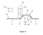
- FIG. 4is a partial cross-sectional of the off-road vehicle taken along the line 4 - 4 of FIG. 2 ;
- FIG. 5is a schematic top plan view of the engine unit of FIG. 3 ;
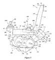
- FIG. 6is a schematic side elevational view of the engine unit and the seat, as well as a portion of a framework of the off-road vehicle that extends next to the engine unit and the seat, and also illustrates a modified air inlet duct shown in phantom;
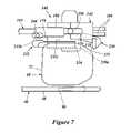
- FIG. 7is a schematic top plan view of the engine unit, the seat and the portion of the off-road vehicle framework shown in FIG. 6 ;
- FIG. 8is a top plan view of an air outlet duct with a portion of the seat shown in phantom;
- FIG. 9is a rear view of the air outlet duct of FIG. 8 with a portion of the seat shown in phantom.
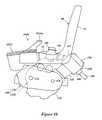
- FIG. 10is a schematic side elevational view of the engine unit, the seat and a modified air intake system
- FIG. 11is a top plan view of a rear portion of a modified off-road vehicle that includes another type of an exhaust system.
- FIG. 12is a side elevational view of the rear portion of the off-road vehicle illustrated FIG. 11 .
- FIGS. 1-7an overall construction of an off-road vehicle is described. While the embodiment is described in connection with this particular type of vehicle, those of skill in the art will appreciate that certain features, aspects and advantages of the present invention may have utility in a wide range of applications for other vehicles, for example, with snowmobiles, tractors, utility vehicles and the like.
- the off-road vehicle 30preferably has an open tubular-type frame 32 .
- the illustrated frame 32comprises a main frame section 34 , a front frame section 36 , a rear frame section 38 and a compartment frame section (or pillar frame section) 40 .
- the main frame section 34includes a pair of side frame units 42 spaced apart side by side with each other.
- Each side frame unit 42comprises a front tubular member 42 a ( FIG. 2 ) and a rear tubular member 42 b ( FIG. 2 ).
- Each tubular member 42 a , 42 bpreferably is rectangularly formed in section, but other configurations can also be used.
- the front and rear members 42 a , 42 bcan have a circular shape in section.
- the members 42 a , 42 bcan have an incomplete tubular shape such as, for example, a U-shape.
- a rear end of the front tubular member 42 ais bent outwardly and is coupled with a mid portion of the rear tubular member 42 b .
- a forward end of the rear tubular member 42 bis bent inwardly and is coupled with a mid portion of the front tubular member 42 a .
- both of the front and rear tubular members 42 a , 42 bare nested together.
- the side frame units 42preferably are connected together by front, center and rear cross members 44 ( FIG. 2 ) that transversely extend between the tubular members 42 a , 42 b.
- the front frame section 36extends generally upward from a front portion of the main frame section 34 .
- the rear frame section 38also extends generally upward from a rear portion of the main frame section 34 .
- the rear frame section 38preferably includes a pair of rear frame members 46 ( FIG. 2 ). Several struts connect the rear frame members 46 to the side members 42 of the main frame section 34 and support the rear frame members 46 above the side members 42 .
- the compartment frame section 40is disposed generally between the front and rear frame sections 36 , 38 in a side view as shown in FIG. 1 .
- the compartment frame section 40includes a pair of compartment members (or pillar members) 48 extending generally upward and higher than the front and rear frame sections 36 , 38 .
- the compartment members 48are spaced apart from each other on both sides of the off-road vehicle 30 to be placed more outward than the main frame section 34 in the illustrated embodiment.
- a floorboard or floor panel 50extends in an area generally defined by the compartment members 48 in a top plan view as shown in FIG. 2 and is affixed at least to the main frame 34 .
- the floorboard 50defines a passenger compartment together with the compartment frame section 40 .
- the illustrated floorboard 50generally is a flat panel with a portion that projects upward. That is, the floorboard 50 comprises a horizontal section 51 defining a generally flat area and a projection 52 defining a tunnel extending along a longitudinal center plane LC ( FIG. 2 ) of the frame 32 that extends vertically and fore to aft.
- the horizontal section 51can support feet of a driver and a passenger and also can be used as a step when the driver or the passenger enters or leaves the passenger area of the off-road vehicle 30 .
- the illustrated projection 52is trapezoidally configured in section and thus has slanted side surfaces 53 and a top surface 54 . Other configurations can also be used.
- the main, front, rear and compartment frame sections 34 , 36 , 38 , 40preferably are welded to each other.
- the illustrated structure and arrangement of the frame 32 , and the combination of the frame 32 and the floorboard 50are merely one example. Various structures, arrangements and combinations other than those are practicable.
- the respective frame sections 34 , 36 , 38 , 40can be provided with struts or reinforcement members that are not described above.
- the off-road vehicle 30preferably has a pair of front wheels 56 and a pair of rear wheels 58 those of which together support the frame 32 .
- Each wheel 56 , 58preferably has a balloon tire (i.e., a tube-less tire) to advantageously proceed over rough roads and in mud and water.
- the balloon tireis relatively wide and air pressure of the tire is relatively high.
- the selected balloon tiresare sized as follows: 25 ⁇ 8 ⁇ 12 at the front end and 25 ⁇ 10 ⁇ 12 at the rear end.
- the front and rear wheels 56 , 58preferably are coupled with the frame 32 through front suspension mechanisms 60 and rear suspension mechanisms 62 , respectively.
- Each front suspension mechanism 60swingably (up and down) and independently suspends the associated front wheel 56 .
- Each rear suspension mechanism 62also swingably (up and down) and independently suspends the associated rear wheel 58 .
- the illustrated off-road vehicle 30preferably features four wheel independent suspension.
- the off-road vehicle 30preferably has a seat unit 66 .
- the illustrated seat unit 66comprises a pair of seats 68 on which the driver and the passenger can sit.
- the seats 68preferably are disposed side by side.
- the rear frame section 38at least in part, forms a pair of seat pedestals (not shown).
- Each seat 68 and each seat pedestaltogether form a seat assembly.
- the illustrated off-road vehicle 30thus has two seat assemblies.
- the seat assembliesare spaced apart from each other to form a space 70 ( FIG. 2 ) therebetween.
- the term “seat unit”may include the space 70 in the broad sense.
- a preferable construction or structure of an off-road vehicle similar to the off-road vehicle 30is disclosed in, for example, co-pending U.S. application Ser. No. 10/791,111 filed on Mar. 2, 2004, titled “ENGINE ARRANGEMENT FOR OFF-ROAD VEHICLE,” co-pending U.S. application Ser. No. 10/791,353 filed on Mar. 2, 2004, titled “DRIVE SYSTEM FOR OFF-ROAD VEHICLE,” co-pending U.S. application Ser. No. 10/790,932 filed on Mar. 2, 2004, titled “AIR INTAKE SYSTEM FOR OFF-ROAD VEHICLE,” co-pending U.S. application Ser. No. 10/792,463 filed on Mar.
- front and forwardmean the direction in which the driver or passenger looks straight when seated on the seats 68 .
- rearmeans the direction opposite to the front direction.
- Each seat 68preferably comprises a seat cushion 72 and a seat back 74 .
- the seat cushion 72extends generally horizontally over the seat pedestal and is detachably or removably affixed to the seat pedestal.
- the seat back 74extends generally vertically and upward from a rear portion of the seat cushion 72 .
- the seat cushion 72 and the seat back 74are formed unitarily.
- the seat cushion 72 and the seat back 74can be separately formed and assembled together.
- the illustrated seat unit 66has a forward end 78 , a rear end 80 and a top end 82 .
- the forward end 78 of the seat unit 66is defined by forward ends of the seat cushions 72 . If, however, the seat pedestals extend forward of than the seat cushions 72 , forward ends of the seat pedestals can define the forward end of the seat unit 66 .
- An imaginary forward, generally vertical plane 84can be defined through the forward end of the seat unit 68 .
- the rear end 80 and the top end 82preferably are defined by rear ends of the seat backs 72 and top ends of the seat backs 74 , respectively.
- An imaginary rearward, generally vertical plane 86can be defined through the rear ends of the seat backs 74 .
- an imaginary, generally horizontal plane 88can be defined through the top ends 82 of the seat backs.
- the seat 68can be shaped in various configurations.
- the seat back 74may be omitted under some circumstances. If the seat back 74 is omitted, the imaginary rear, generally vertical plane 86 can be defined more forwardly as indicated by the reference numeral 86 A.
- the rear, generally vertical plane 86may be defined more forwardly as indicated by the reference numeral 86 B if the thickness of the seat back 74 is reduced.
- the generally horizontal plane 88may be shifted downward to a top surface 72 a of each of the seat cushions 72 as indicated by the reference numeral 88 A.
- each seat cushion 72undulates and has a recessed portion 72 a R that is positioned lower than the horizontal plane 88 A just in front of the seat back 74 .
- the driver or the passengersits in the recessed portion 72 a R of the respective seat 68 .
- the forward, rear and top ends 78 , 86 , 82 , the imaginary forward and rear generally vertical planes 84 , 86 and the imaginary generally horizontal plane 88are normally determined depending on a configuration of the seat assembly, which includes the seat 68 and the seat pedestal in the illustrated arrangement. More practically, the rear end 86 should be substantially on the imaginary, generally vertical forward plane 86 A or the imaginary, generally vertical rear plane 86 B. Also, the top end 82 should be substantially the upper-most end of the seat cushions 72 and should be on the imaginary, generally horizontal plane 88 A. Because the seats 68 are positioned on the seat pedestals which have a certain height, a relatively large space is formed lower than the imaginary, generally horizontal plane 88 A.
- the seat unit 66can have other number of seats such as, for example, three seats in some alternative arrangements.
- the seats 68can be made of any soft materials such as, for example, but without limitation, cloth, rubber, sponge or styrene foam. Further, the seats 68 can be made of hard materials rather than the soft materials. For example, metal, hard plastic or wood can be used.
- the respective compartment members 48 on both sidespreferably have an arm rest 90 , although only the arm rest 90 on the left-hand side is illustrated.
- Each arm rest 90preferably is affixed to a portion of each compartment member 48 for pivotal movement about a pivot axis that extends transversely relative to the associated compartment member 48 .
- the arm rest 90thus can move between a fully extended position (illustrated by solid lines in the figures) and a fully retracted position (illustrated by phantom lines in the figures).
- the arm rest 90can be held generally horizontally when the arm rest 90 lies in the fully extended position.
- the arm rest 90can generally extend parallel to the compartment member 48 when the arm rest 90 lies in the fully retracted position.
- the driver or the passengercan place one of his or her arm(s) on the arm rest while sitting on the seat(s) 68 .
- conventional seat beltssuch as, for example, three-point retaining type seat belts can hold the driver and the passenger in an appropriate position on the seats 68 .
- Metal fittings that fix the seat beltspreferably are positioned in the compartment area defined by the compartment frame 40 such that the fittings cannot be caught by branches or twigs of trees while the off-road vehicle 30 proceeds in a forest or woods. In other words, the metal fittings preferably are not exposed out of the compartment area.
- the off-road vehicle 30preferably has a carrier or cargo box 92 behind the seat unit 66 .
- the illustrated carrier 92extends over a rear portion of the rear frame section 38 and is suitably affixed at least to the rear frame members 46 .
- the carrier 92can be tipped rearward to allow its contents to be dumped.
- the carrier 92preferably is formed generally in the shape of a rectangular parallelepiped and has a bottom, a front, a rear, and a pair of lateral sides. That is, the carrier 92 is generally configured as an open-topped box.
- the bottom of the carrier 92preferably comprises steps 96 on both sides such that side portions 98 of the bottom are positioned higher than a center portion 100 of the bottom.
- the steps 96advantageously reduce the likelihood that the rear wheels 58 will contact the carrier 92 when the rear wheels 58 are in an uppermost position of the suspension travel. It should be noted that the described movement of the rear wheels 58 is the relative movement thereof in relation to the carrier 92 .
- the center bottom portion 100thus increases the capacity of the carrier 92 .
- Each 96preferably extends fore to aft as shown in FIG. 2 . Longitudinally shortened steps (similar to wheel wells) also can be used.
- the center bottom portion 100helps lower the center of gravity of the carrier 92 .
- the illustrated off-road vehicle 30thus features enhanced stability.
- the steps 96also reduce lateral movement of loads. Additionally, the manufacture of the carrier 92 is simple and cost effective because the steps 96 only extend fore to aft. The steps 96 also can increase the stiffness of the carrier 92 .
- the off-road vehicle 30comprises a steering system 104 .
- the steering system 104 in the illustrated embodimentincludes a steering wheel 106 and a steering shaft unit 110 .
- the steering shaft unit 110is disposed on the frame 32 for steering movement in front of the seat 68 , which is located on the left-hand side of the illustrated off-road vehicle 30 .
- the illustrated steering shaft unit 110comprises an upper steering shaft 116 and a lower steering shaft 118 both pivotally affixed to the frame 32 .
- the upper shaft 116extends generally upward and is inclined rearward toward the driver's area.
- the steering wheel 106is affixed to the top end of the upper shaft 116 . The driver thus can operate the steering wheel 106 while seated on the seat 68 .
- the lower shaft 118extends toward the other part of the steering system 104 .
- the other part of the steering system 104is structured to direct the front wheels 56 right or left relative to the longitudinal center plane LC of the frame 32 in response to the steering movement of the steering wheel 106 .
- the other part of the steering system 104preferably includes a pair of tie-rods (not shown) coupled to both the front wheels 56 and a rack-and-pinion assembly (not shown) connecting the lower shaft 118 with the tie-rods (not shown).
- the rack-and-pinion assembly in the illustrated embodimentis disposed on a front differential gear unit 119 , which will be described below.
- an inclination angle of the upper steering shaft 116is adjustable such that a position of the steering wheel 106 can be moved to fit various heights of drivers.
- a ratchet-type tilt devicecan be used to adjust the inclination angle of the upper steering shaft 116 .
- a hood or bonnet 120preferably covers a front portion of the frame 32 .
- the hood 120comprises a top surface section, a front surface section and a pair of lateral side sections.
- Those sectionscan be unitarily formed with a piece of sheet metal and can be made in, for example, a press process. In one variation, separate pieces of the sections can be affixed together, for example, by welding. Other materials such as, for example, a plastic material can be used. Also, other conventional manners can be applied to produce the hood 120 .
- the illustrated hood 120covers the main frame section 34 , the front frame section 36 , the front wheels 56 and a major portion of the steering system 104 .
- a dashboard 122preferably depends from a rear end of the hood 120 and faces the passenger compartment.
- a meter unit 124is disposed in a center area of the dashboard 122 .
- the meter unit 124preferably incorporates meters and/or gauges such as, for example, a speedometer, a fuel level meter and the like. Because of this meter unit arrangement, the driver can easily view the individual meters at a glance.
- the top surface section of the hood 120preferably inclines downward toward the front surface section of the hood 120 .
- the hood front surface sectionextends downwardly (preferably in a generally vertical manner) from the top surface section of the hood.
- a front bumper 126extends from the side frame units 42 forwardly and upwardly to protect the front surface section of the hood 120 .
- a radiator or heat exchanger 128preferably is disposed between the front surface section of the hood 120 and the front frame section 36 .
- the radiator 128can be used to cool coolant (e.g., water) that is used in a cooling system.
- the radiator 128can be affixed to the front frame section 36 .
- the radiator 128preferably has a fan 130 to cool heated coolant that flows through the radiator 128 .
- a battery 132is preferably disposed under the hood 120 and generally behind the radiator 128 .
- the battery 132can be placed on a stay or bracket extending from the front frame section 36 and can be affixed to the stay or bracket in a proper manner.
- the illustrated buttery 132is positioned above the front differential gear unit 119 . At least a top surface of the battery 132 is positioned at almost the same elevation as the seat cushions 72 in the illustrated arrangement.
- the above-described position of the battery 132which has significant weight, improves the weight balance of the off-road vehicle 30 . That is, the center of the gravity of the off-road vehicle 30 can be shifted forward by spacing the battery 132 well apart from an engine unit of the off-road vehicle, which preferably is disposed between the seats 68 as described shortly.
- the battery 132 in this locationalso can be cooled by the fan 130 of the radiator 128 .
- the battery 132is less likely to be submerged in water even when the wheels 56 , 58 are submerged.
- no spaceis necessary for the battery 132 under or around the seats 68 .
- the space under or around the seats 68can be used for placing other large components such as, for example, a fuel tank and a luggage box, as well as can be used for other for other purposes.
- the off-road vehicle 30has a prime mover that powers the off-road vehicle 30 and particularly the front and rear wheels 56 , 58 .
- the prime moverpreferably is an internal combustion engine 142 .
- an electric motorcan replace the engine 142 .
- Engine poweris transferred to the front and rear wheels 56 , 58 through a suitable transmission 144 and a suitable drive system 146 .
- the engine 142 and the transmission 144are coupled together to form the engine unit, which now is indicated by the reference numeral 148 .
- the engine 142includes foregoing cooling system mentioned above.
- the illustrated transmission 144advantageously includes an endless V-belt transmission mechanism 144 a and a switchover mechanism 144 b .
- the illustrated drive system 146comprises a forward driveshaft 150 extending forward from the engine unit 148 , a rear driveshaft 152 extending rearward from the engine unit 148 .
- a front differential gear unit 119is coupled with the front axles (not shown) of the front wheels 56
- a rear differential gear unit 154is coupled with the rear axles (not shown) of the rear wheels 58 .
- a single axlecan replace the half axles.
- the forward driveshaft 150preferably extends through the tunnel defined by the projection 52 of the floorboard 50 .
- the forward driveshaft 150is positioned under the top surface 54 of the projection 52 of the floorboard 50 and is positioned higher than the horizontal section 51 of the floorboard 50 . In this position, the forward driveshaft 150 is less likely to be hit by rocks, wooden blocks or the like.
- the engine unit 148preferably is positioned generally in the space 70 defined between the seat assemblies.
- the illustrated engine 142operates on a four-stroke combustion principle; however, other operating principles can be used (e.g., 2 stroke and rotary).
- the engine 142preferably has a single cylinder block 158 that extends generally upward and rearward from a lower section of the engine unit 148 . That is, the cylinder block 158 has a cylinder axis CA that inclines relative to vertical at a certain angle.
- the illustrated cylinder axis CAinclines from vertical at approximately 45 degrees.
- the engine 142is an internal combustion engine.
- the cylinder block 158preferably defines a cylinder bore (not shown) therein.
- a piston(not shown) is reciprocally disposed within the cylinder bore (not shown).
- a cylinder head 160preferably closes an upper end of the cylinder bore to define, together with the cylinder bore and the piston, a combustion chamber 163 .
- the cylinder head 160also defines a pair of intake ports 162 and a pair of exhaust ports 166 that communicate with the combustion chamber 163 .
- An intake valvecan be provided at each intake port 162 to selectively open the combustion chamber 163 to an air intake system 164 .
- the air intake system 164is coupled with the intake ports 162 at a front surface 165 of the cylinder head 160 .
- the front surface 165 of the cylinder head 160preferably is disposed substantially within the space 70 and preferably faces generally forward and upward. With reference to FIG. 2 , the front surface 165 desirably is disposed generally between the seats 68 .
- the air intake system 164introduces air into the combustion chamber 163 through the intake ports 162 when the intake valves (not shown) open the passage into the combustion chamber 163 .
- An exhaust valve(not shown) also is provided at each exhaust port 166 to selectively open the combustion chamber 163 to an exhaust system 168 .
- the exhaust system 168is coupled with the exhaust ports 166 at a rear surface 169 of the cylinder head 160 .
- the rear surface 169 of the cylinder head 160is positioned substantially opposite to the front surface 165 and generally faces rearward and downward.
- the exhaust system 168routes exhaust gases from the combustion chamber 163 to an outside location.
- a cylinder head cover 170is attached to the cylinder head 160 to enclose one or more camshafts (not shown).
- the camshafts (not shown)preferably are journaled on the cylinder head 160 .
- the camshafts (not shown)actuate the intake and exhaust valves at speeds that are generally in proportion to the engine speed. Other suitable methods of actuating the valves also can be used.
- An upper section of the illustrated engine unit 148includes the cylinder block 158 , the cylinder head 160 and the cylinder head cover 170 .
- the upper sectionat least in part extends rearward beyond the imaginary rear, generally-vertical plane 86 (and 86 A or 86 B).
- a lower section of the engine unit 148which is the balance of the engine unit 148 , comprises a crankcase 174 , which closes a lower end of the cylinder bore (not shown).
- a crankshaft 176preferably is journaled within the crankcase 174 and is coupled with the piston (not shown) in any suitable manner. In the illustrated arrangement, the crankshaft 176 extends generally transverse to a direction of travel of the vehicle but other orientations also can be used. The reciprocal movement of the piston results in rotation of the crankshaft 176 .
- the crankshaft 176preferably drives the camshafts via a camshaft drive mechanism.
- the crankcase 174also houses an input shaft for a shiftable portion of the transmission 144 .
- the input shaftis positioned forward of the crankshaft 176 .
- the lower section of the engine unit 148also comprises a V-belt housing 178 , which is positioned next to the crankcase 174 in the illustrated arrangement.
- the V-belt housing 178is defined on the left-hand side of the crankcase 174 .
- the V-belt housing 178houses the V-belt transmission mechanism (e.g., continuously variable transmission).
- the lower section of the engine unit 148(which comprises at least the crankcase 174 and the V-belt housing 178 ) houses the transmission 144 .
- the transmission 144will be described in greater detail below.
- the illustrated air intake system 164extends forward to a location under the hood 120 from the intake ports 162 of the engine 142 .
- the intake system 164preferably comprises an air cleaner unit 182 and an air delivery conduit 183 which is formed with the remainder part of the intake system 164 other than the air cleaner unit 182 .
- the air delivery conduit 183preferably includes an air intake duct 184 and a throttle body or carburetor 186 .
- the illustrated air intake duct 184includes an accumulator or plenum chamber 188 .
- the throttle body 186 in the illustrated embodimentis connected to the intake ports 162 through an air intake conduit 192 .
- the throttle body 186comprises a throttle valve 194 that regulates a rate of airflow amount delivered to the combustion chamber 163 .
- the throttle valve 194preferably is a butterfly valve and generally is journaled for pivotal movement. The level of airflow depends on an angular position of the throttle valve 194 —when the throttle valve is closed or substantially closed, minimal air flow results, while when the throttle valve is opened or substantially opened, maximum air flow results.
- An accelerator pedal or control member 196( FIG. 4 ) preferably is disposed at a front end of the floorboard 50 for pivotal movement to control the position of the throttle valve 194 .
- a throttle cableconnects the accelerator pedal 196 to the throttle valve 194 .
- the driverthus can control the throttle valve 194 by adjusting an angular position of the accelerator pedal 196 with his or her own foot 198 .
- Other suitable mechanisms and electronic connectionsalso can be used to transmit operator demand to the throttle valve or engine.
- the throttle body (e.g., the carburetor) 186which functions as a charge former, preferably also has a fuel measurement mechanism that measures an amount of fuel mixed with the air in accordance with the rate of airflow. Because of this fuel measurement mechanism, air/fuel ration supplied to the engine can be controlled and/or optimized depending upon engine operating conditions.
- the fuelis delivered to the throttle body 186 from a fuel tank (not shown) that can be suitably mounted and suitably position on the frame 32 .
- the fuel injection systemhas a fuel injector that is configured to spray fuel directly into the combustion chamber 163 or into a portion of the air intake system downstream of the throttle valve.
- An engine control unitcan control the amount of furl injected, for example, in accordance with the airflow rate.
- the accumulator 188can be coupled with an inlet of the throttle body 186 .
- the accumulator 188generally forms a portion of the intake duct 184 but provides a larger volume, which is due to a larger cross-sectional flow area, than the rest portion of the intake duct 184 to temporarily accumulate air delivered to the throttle body 186 .
- Such a constructionallows air to accumulate before delivery to the throttle body 182 .
- the accumulator 188is useful to expedite delivering of the air to the combustion chamber when the demand on engine load rapidly increases.
- the accumulator 188generally has an arcuate configuration. Such a construction advantageously smoothens the delivery of air to the engine.
- the accumulator 184has a relatively large volume and is disposed next to the throttle body 182 , the intake efficiency of the induction system is greatly improved. That is, sufficient air can be quickly supplied to the engine even when the engine is being operated at a relatively high engine speed.
- the air intake conduit 192 , the throttle body 182 and the accumulator 184together extend forwardly of the engine within a region defined between the seats 68 .
- Upper portions of the throttle body 182 and the accumulator 184preferably are positioned slightly higher than the top ends 82 A of the seat cushions 72 .
- a forward-most portion of the accumulator 184turns downward at or just forward of the forward end of the seat assemblies.
- the throttle body 182 and at least a portion of the accumulator 184are interposed between the seat assemblies and are positioned within, or just adjacent to, the space 70 .
- the throttle body 182 and the accumulator 184are positioned within a protective region of the vehicle that is located higher than a lowermost surface of the frame assembly or the floorboard 50 .
- Such positioningreduces the likelihood that dirt and other road debris that may be kicked up underneath the vehicle will damage the throttle body 182 or the accumulator 184 .
- Such placementalso facilitates servicing of these components and protects these components from water damage while fording a stream, a mud bog or the like.
- the illustrated accumulator 184which is positioned within the most downstream portion of the illustrated intake duct 186 , ends above a lowermost surface defined by the rear frame section 38 .
- the balance of the air intake duct 186which has a smaller volume or cross-sectional area than the accumulator 184 , preferably comprises a downstream section 200 , a middle section 202 and an upstream section 204 , which are provide a contiguous air flow path in the illustrated embodiment.
- the downstream section 200extends downwardly from the accumulator 184 to a lowermost portion of the rear frame section 38 .
- the middle section 202extends forwardly in a generally horizontal direction from a lower end of the downstream section 200 .
- the middle section 202extends through a tunnel defined by the projection 52 of the floorboard 50 . Because of this arrangement, the middle section 202 advantageously is positioned higher than the horizontal section 51 of the floorboard 50 , which greatly reduces the likelihood of damage from rocks, sticks, road debris or the like. Furthermore, the driver and/or the passenger-are able to maintain a good riding body position because the horizontal section 51 is positioned generally vertically lower than the middle section 202 . Moreover, the illustrated arrangement contributes to a lower center of gravity for the off-road vehicle 30 because the height of the seats 68 does not need to be increased to accommodate the middle section 202 or another portion of the air induction system.
- the middle section 202preferably ends at a location close to the front frame section 36 .
- the upstream section 204extends generally vertically upward from the middle section 202 .
- the upstream section 204preferably is positioned within a space defined below the hood 134 .
- the forward-most portion of the upstream section 204extends forward and slightly downward along a lower surface of the hood 134 .
- an upstream end portion 204 a of the upstream section 204which is located next to the air cleaner unit 182 , turns upwardly and is positioned higher than at least an air outlet port of the air cleaner unit 182 which opens at a rear end 205 of the air cleaner unit 182 .
- the air cleaner unit 188preferably is attached to the upstream end of the intake duct 186 and extends generally along the lower surface of the hood 134 .
- the illustrated air cleaner unit 188has a relatively large volume and has a cleaner element therein.
- the air cleaner unit 188also has an air inlet port that opens at a front end 206 of the cleaner unit 188 .
- the inlet portpreferably is positioned at least higher than the respective top ends 56 a , 58 a of the wheels 56 , 58 and more preferably higher than the top surfaces 72 a of the seat cushions 72 . Because of this arrangement, water is not likely to enter the air cleaner unit 182 even when the off-road vehicle 30 travels through water streams, mountain torrents or muddy pools. Ambient air is drawn into the air cleaner unit 188 through the air inlet port and passes through the filtration element such that foreign substances such as, for example, dust, mud or water can be substantially removed from the air that is being introduced into the engine.
- the airwhich has been cleaned in the cleaner unit 188 , flows to the accumulator 188 through the rest part of the intake duct 184 .
- the airflow amountis regulated by the throttle valve 194 in the throttle body 186 .
- an amount of fuelis measured by the fuel amount measurement mechanism in the throttle body 186 in response to the air amount.
- An air/fuel charge that has a proper air/fuel ratiois formed and is delivered to the combustion chamber 163 when the intake valves open the intake ports 162 .
- the air/fuel chargeis ignited by an ignition system (not shown) and burns within the combustion chamber 163 .
- the burning of the chargecauses expansion of the gases and increased pressure that results in movement of the piston 159 .
- the crankshaft 176is rotated within the crankcase 174 by the movement of the piston 159 .
- a modified air intake system 164 Acan have an air cleaner unit 182 A that is directly coupled with the throttle body 186 .
- the devices, units, components, members and portions thereof that have been already described aboveare assigned with the same reference numerals and will not be repeatedly described. Also, similar devices, units, components, members and portions thereof are assigned with the same reference numerals with the letter “A” and will not be described in detail.
- the air cleaner unit 182 Ais positioned in the space 70 defined by the seats 68 .
- the air cleaner unit 182 Apreferably has an air inlet port 182 Aa that extends upward from a rear top surface of the unit 182 A.
- the illustrated inlet port 182 Aapreferably is positioned higher than the top surfaces of the respective seat cushions 72 and more preferably higher than a top surface of the throttle body 186 .
- the illustrated exhaust system 168preferably comprises a pair of exhaust conduits 208 and a muffler 210 .
- the exhaust conduits 208are coupled with the respective exhaust ports 166 and extend generally rearward.
- the exhaust conduits 208extend generally parallel to each other.
- the exhaust conduits 208have a wavy shape that serpentines up and down, as shown in FIGS. 1 and 2 .
- Rearward ends of the exhaust conduits 208preferably extend beyond a rear end of the rear frame section 38 .
- the muffler 210is coupled with the rear ends of the exhaust conduits 208 .
- the muffler 210preferably has a cylindrical shape.
- a center axis of the muffler 210preferably extends in a generally transverse direction relative to the longitudinal center plane LC of the frame 32 .
- the muffler 210has a relatively large volume to reduce exhaust energy and noise.
- An outlet port 212can be formed at a side surface, which is on a left-hand side in the illustrated embodiment. Other arrangements also can be used.
- the exhaust gasesflow through the exhaust conduits 208 and are discharged through the outlet port 212 of the muffler 210 .
- the exhaust system 168 in the illustrated embodimenthas the relatively long exhaust conduits 208 , the exhaust energy can be sufficiently reduced.
- the muffler 210which has a relatively large weight, is disposed at the end of the frame 32 .
- a modified exhaust system 168 Acan include a muffler 210 A that is disposed at a location closer to a midpoint of the frame 32 .
- the devices, units, components, members and portions thereof that have been already described aboveare assigned with the same reference numerals and will not be repeatedly-described. Also, similar devices, units, components, members and portions thereof are assigned with the same reference numerals with the letter “A” and will not be described in detail.
- the muffler 210 A in this modified embodimentpreferably is disposed directly behind the engine unit 148 and is affixed to the rear frame members 46 .
- An outlet port 212 A of the muffler 210 Ais positioned on the right-hand side thereof.
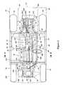
- the change speed mechanism 144 b and the V-belt transmission mechanism 144 atogether have a common output shaft 216 .
- the output shaft 216extends generally parallel to the crankshaft 176 at a location in front of the crankshaft 176 .
- the output shaft 216preferably extends through the crankcase 174 and the V-belt housing 178 and is journaled for rotation relative to these components. Because of this arrangement, the output shaft 216 is positioned at a location generally between the front wheels 56 and the crankshaft 176 . In other words, the crankshaft 176 is positioned between the output shaft 216 and the rear wheels 58 .
- the crankshaft 176extends into the V-belt housing 178 and carries a drive pulley 218 .
- the output shaft 216carries a driven pulley 220 .
- the drive and driven pulleys 218 , 220both comprise an axially fixed pulley member and an axially movable pulley member that is movable along the respective axis of the crankshaft 176 or the output shaft 216 . Together, the pulley members form a V-shaped valley that expands and contracts with changes in engine speed.
- An endless transmitter (e.g., a belt or a chain) 222is wound around the drive pulley 218 and the driven pulley 220 .
- the transmitter 222is a V-type belt and has a V-configuration in section.
- the movable pulley member of the drive pulley 218is urged to stay apart from the fixed pulley member by the bias force of a bias member such as, for example, a spring.
- the movable pulley member of the driven pulley 220is urged to stay close to the fixed pulley member by the bias force of a bias member such as, for example, a spring.
- Each movable pulley membercan move axially against the bias force by a clutch mechanism which is provided on either the pulley 218 , 220 .
- the clutch mechanismacts by centrifugal force created when the crankshaft or output shaft turns at a speed higher than a preset speed.
- the change in diameter of one pulleycauses a corresponding change in the other pulley.
- both diameters of the drive pulley 218 and the driven pulley 220vary to automatically change the transmission ratio between the drive pulley 218 and the driven pulley 220 normally in response to the engine speed.
- the transmission 144has a cooling system that preferably introduces ambient air into the v-belt housing 178 and discharges the air to an external location outside of the housing 178 .
- the V-belt housing 178preferably has an air inlet port 226 at a rear end and an air outlet port 228 at a front end.
- An air inlet duct 230is coupled to the inlet port 226
- an air outlet duct 232is coupled to the outlet port 228 .
- a downstream end 230 a of the inlet duct 230is joined to the inlet port 226 of the V-belt housing 178 .
- the inlet duct 230has a horizontal portion 230 b and a vertical potion 230 c.
- the horizontal portion 230 bextends generally rearward from the downstream end 230 a .
- the air inlet port 226 of the V-belt housing 178is positioned in front of the imaginary rearward, generally vertical plane 86 ( FIG. 3 ) that includes the rearmost end 80 of the seat 68 .
- a large part of the horizontal portion 230 bis positioned between the seat assemblies.
- the vertical portion 230 cextends generally upward from the horizontal portion 230 b to a location generally behind the seat back 74 , on the left-hand side in the illustrated embodiment.
- the vertical portion 230 cgenerally extends entirely behind the imaginary rearward, generally vertical plane 86 ( FIG. 3 ).
- the inlet duct 230preferably has an inlet opening 233 at its upstream end.
- the inlet opening 233faces forward and is disposed at the upper end of the inlet duct 230 .
- the inlet opening 233preferably is positioned at almost the same elevation as the top surfaces 72 a of the seat cushions 72 .
- the inlet opening 233is positioned slightly higher than the recessed portions 72 a R of the top surfaces 72 a . In this position, the inlet opening 233 can efficiently draw the ambient air that flows generally between the seats 68 .
- Cooling airis introduced into the V-belt housing 178 through the inlet duct 230 and the air inlet port 226 when the crankshaft 176 , the output shaft 216 and the drive and driven pulleys 218 , 220 rotate.
- one or both of the pulleyscan be provided with fan blades to help induce higher speed air flow as the engine speed increases.
- Other embodimentscan provide a ram air type of air flow. Having circulated with the belt chamber of the transmission, the air then is discharged through the outlet port 228 aid the outlet duct 232 .
- a modified inlet duct 230 Acan extends toward a location almost the same elevation of the top end of the seat backs 74 and has an inlet opening 233 A that is directed rearward. As so arranged, the inlet opening 233 A can advantageously draw the air that is not heated by the engine 142 .
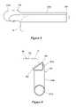
- the outlet duct 232preferably has a vertical portion 232 b and a horizontal portion 232 c .
- a bottom of the illustrated vertical portion 232 bslightly turns rearward toward the outlet port 228 of the V-belt housing 178 .
- An upstream end 232 awhich is a lower distal end of the outlet duct 232 , is joined to the outlet port 228 of the V-belt housing 178 .
- the vertical portion 232 bextends generally upward from the upstream end 232 a in front of the V-belt housing 178 toward a location higher than a top end of the V-belt housing 178 .
- the horizontal portion 232 cpreferably defines an uppermost portion of the outlet duct 232 .
- the horizontal portion 232 cextends rearward from the vertical section 232 b and generally along a bottom surface of one of the seat cushions 72 , on the left-hand side in the illustrated embodiment. In other words, the horizontal portion 232 c extends close to the seat cushion 72 and generally at the same level as to top of the seat cushions 72 . Almost the entire body of the horizontal portion 232 c lies concealed between the seat assemblies.
- the outlet duct 232preferably has an outlet opening 234 at its downstream end.
- the outlet opening 234preferably is directed rearward.
- the illustrated outlet opening 234is positioned nearly to the rear end of the associated seat cushion 72 .
- the horizontal portion 232 c of the outlet duct 232 in the illustrated embodimenthas a configuration corresponding to a configuration of the associated seat cushion 72 .
- the seat cushion 72has a slant surface 72 a on its side such that the seat cushion 72 becomes narrower toward a bottom end from a top end.
- the horizontal portion 232 c of the outlet duct 232generally has a triangular shape in section with its hypotenuse extending next to the slant surface 72 a of the seat cushion 72 .
- the seat cushion 72 and the horizontal portion 232 c of the outlet duct 232can nest together.
- the ambient airis introduced into the V-belt housing 178 through the inlet duct 230 and is discharged through the outlet duct 232 which the pulleys 218 , 220 rotating within the V-belt housing 178 .
- the airflow through the housing 178prevents the heat from building and thus keeps the belt 222 and the pulleys 218 , 220 relatively cool. Belt deterioration due to heat this is reduced and/or slowed.
- both the inlet opening 233 of the inlet duct 230 and the outlet opening 234 of the outlet duct 232are positioned at elevations higher than the respective top surfaces 56 a , 58 a of the wheels 56 , 58 .
- waterwill not enter the V-belt housing 178 .
- the outlet opening 234 of the outlet duct 232is directed rearward at nearly the rear ends of the seat cushions 72 as described above.
- the noise in the V-belt housing 178is channeled rearward and is hardly audible to the driver and/or the passenger.
- the inlet opening 233 of the inlet duct 230 and the inlet opening 233 A of the modified inlet duct 230 Aare positioned behind the seat backs 74 , any noise associated with the airflow into the intake duct generally will not disturb the driver and/or the passenger.
- further isolation of driver/passenger from such noiseis achieved with a rearward facing inlet opening, such as the inlet opening 233 A, shown in FIG. 6 .
- the illustrated horizontal portion 232 c of the outlet duct 232does not lessen the appearance of the off-road vehicle 30 , because the horizontal portion 232 c lies generally concealed between the seat assemblies.
- a large part of the horizontal portion 232 ccan be placed under one of the seat cushions 72 because of its configuration which corresponds to the slant surface 72 a of the seat cushion 72 . This feature is useful not only for appearance but also to make the off-road vehicle 30 compact.
- the engine output that has been transferred to the output shaft 216 through the V-belt mechanismis transferred to the drive mechanism 146 through the change speed transmission mechanism.
- This mechanismpreferably is configured to provide a parking state, a high speed forward state, a neutral state, a low speed forward state, and a reverse state.
- the mechanismpreferably comprises a suitable gear train that allows an operator to select among at least the above-mentioned operating states.
- a bevel gear assembly 236can be coupled with the mechanism.
- the mechanismalso comprises a shift lever unit 240 that extends from the crankcase 174 .
- the shift lever unit 240preferably is connected to the rest of the switchover mechanism within the crankcase 174 through a suitable linkage (not shown).
- the shift lever unit 240preferably is placed generally within the space defined between the seats 68 .
- the illustrated lever unit 240is positioned generally at the forward-most portion of the space. Such placement facilitates ease of use.
- the shift lever unit 240preferably comprises a lever 244 and a lever cover 246 .
- the lever 244preferably is affixed to the frame 32 directly or indirectly for pivotal movement around a fulcrum.
- the shift lever unit 240can comprise a lever that moves axially. The driver thus can control the change speed mechanism in the crankcase 174 and vary the transmission operating state among at least the parking state, the high speed forward state, the neutral state, the low speed forward state, and the reverse state by operating the lever 244 .
- the shift lever unit 240is positioned close proximity to the change speed mechanism of the transmission 144 .
- the linkagethus can be short enough to make the switchover mechanism compact and also to improve the feeling that the driver might have when operating the shift lever unit 240 .
- the output of the change speed mechanism 144 bis transferred to the drive system 146 through the bevel gear 236 .
- the forward driveshaft 150 of the drive system 146is pivotally coupled with a forward differential input shaft (not shown) of the forward differential gear unit 119 .
- the forward differential input shaftis connected to the front wheels 56 through a differential mechanism formed within the forward differential gear unit 119 .
- the rear driveshaft 152is coupled with a rear differential input shaft (not shown) of the rear differential gear unit 154 .
- the rear differential input shaftis coupled with the rear wheels 58 through another differential mechanism formed within the rear differential gear unit 154 .
- the engine unit 148can have systems, devices, components and members other than those described above.
- the illustrated engine 142employs a starter motor that starts the engine 142 .
- the off-road vehicle 30preferably has other devices, components and members.
- the differentialscan be selectively lockable such that the differential function can be eliminated on demand.
- a brake systemcan be provided to slow or stop rotation of the wheels 56 , 58 or another drive train component (e.g., the driveshafts).
- a brake pedal 270( FIG. 5 ) can be disposed next to the accelerator pedal 196 and can be connected to brake units that are coupled with the wheels 56 , 58 .
- the brake unitscan comprise disk brake configurations. The driver thus can stop the off-road vehicle 30 by operating the brake pedal 270 .
- the engine 142is located generally rearward of the change speed mechanism including the output shaft 216 . Moreover, the engine is positioned generally rearward of, and lower than, the seating area. Thus, heat generated by the engine 142 can be substantially isolated from the driver and/or the passenger, and particularly isolated from the feet of those persons both when seating and when mounting or dismounting from the vehicle.
- the cylinder block 158 , the cylinder head 160 and the cylinder head cover 170 in this arrangementgenerally are directed rearward and are positioned generally rearward of the occupants. Thus, it is very unlikely that the engine heat will affect the occupants of the vehicle.
- the exhaust system 168carries a great deal of heat as well while the intake system 164 and the charge former, e.g., the throttle body 182 , generally do not generate or conduct much heat.
- the intake system 164 and the charge formerare generally protected from heat carried by the exhaust system 168 because the exhaust system 168 is positioned opposite to the intake system 164 in the illustrated arrangement.
- the engine heat and the exhaust heatcan be generally isolated from the intake system 164 during forward operation of the off-road vehicle 30 .
- the temperature of the intake airtherefore, is not greatly affected by the heat generated during operation of the off-road vehicle 30 and engine output efficiency can be kept in good condition.
- placement of a radiatorpreferably is generally below the air intake such that heat generated in the region of the radiator does not adversely affect engine performance through-heating of the air inducted into the engine.
- the intake system 164generally does not extend along a heat generating or conducting surface of the engine 142 .
- the engine heatis generally isolated from the intake system 164 in this arrangement.
- the illustrated air cleaner 188is greatly spaced from the engine 142 . As such, any air that is heated by the engine 142 and the exhaust system 168 will not be drawn into the air intake system 164 , which improves the engine output efficiency. Additionally, due to the elevated nature of the air inlet and air cleaner 188 , water also is very unlikely to be drawn into the intake system 164 . Furthermore, because the air cleaner 188 is positioned below the hood 134 , water is unlikely to splash its way into the air cleaner.
- the exhaust conduits 208extend along a relatively lower portion of the off-road vehicle 30 in the illustrated arrangement because the exhaust conduits 208 are directed generally downward and rearward instead a wrapping around from a forward or lateral surface of the engine.
- the exhaust conduits 208thus, are sufficiently spaced apart from the driver and/or the passenger.
- the seats 68can be positioned closer to the engine 142 , which allows a narrower overall construction for the vehicle or a closer mounting of the split seats 68 .
Landscapes
- Engineering & Computer Science (AREA)
- Chemical & Material Sciences (AREA)
- Combustion & Propulsion (AREA)
- Transportation (AREA)
- Mechanical Engineering (AREA)
- Body Structure For Vehicles (AREA)
Abstract
Description
Claims (42)
Priority Applications (2)
| Application Number | Priority Date | Filing Date | Title |
|---|---|---|---|
| US10/803,274US7438147B2 (en) | 2003-04-02 | 2004-03-18 | Transmission for off-road vehicle |
| US11/775,442US7690472B2 (en) | 2003-04-02 | 2007-07-10 | Transmission for off-road vehicle |
Applications Claiming Priority (2)
| Application Number | Priority Date | Filing Date | Title |
|---|---|---|---|
| US45994603P | 2003-04-02 | 2003-04-02 | |
| US10/803,274US7438147B2 (en) | 2003-04-02 | 2004-03-18 | Transmission for off-road vehicle |
Related Child Applications (1)
| Application Number | Title | Priority Date | Filing Date |
|---|---|---|---|
| US11/775,442ContinuationUS7690472B2 (en) | 2003-04-02 | 2007-07-10 | Transmission for off-road vehicle |
Publications (2)
| Publication Number | Publication Date |
|---|---|
| US20040195034A1 US20040195034A1 (en) | 2004-10-07 |
| US7438147B2true US7438147B2 (en) | 2008-10-21 |
Family
ID=33101391
Family Applications (2)
| Application Number | Title | Priority Date | Filing Date |
|---|---|---|---|
| US10/803,274Expired - LifetimeUS7438147B2 (en) | 2003-04-02 | 2004-03-18 | Transmission for off-road vehicle |
| US11/775,442Expired - LifetimeUS7690472B2 (en) | 2003-04-02 | 2007-07-10 | Transmission for off-road vehicle |
Family Applications After (1)
| Application Number | Title | Priority Date | Filing Date |
|---|---|---|---|
| US11/775,442Expired - LifetimeUS7690472B2 (en) | 2003-04-02 | 2007-07-10 | Transmission for off-road vehicle |
Country Status (1)
| Country | Link |
|---|---|
| US (2) | US7438147B2 (en) |
Cited By (30)
| Publication number | Priority date | Publication date | Assignee | Title |
|---|---|---|---|---|
| US20090309082A1 (en)* | 2008-06-11 | 2009-12-17 | Warn Industries, Inc. | Fan Cooled Winch |
| US7669686B1 (en)* | 2006-05-01 | 2010-03-02 | Brp-Powertrain Gmbh & Co Kg | Parking locking mechanism for vehicle |
| US20100078240A1 (en)* | 2008-09-30 | 2010-04-01 | Honda Motor Co., Ltd. | Intake structure of vehicle |
| US20100155170A1 (en)* | 2008-12-22 | 2010-06-24 | Melvin Timothy F | Vehicle |
| US7931106B1 (en)* | 2009-10-23 | 2011-04-26 | Yamaha Hatsudoki Kabushiki Kaisha | All terrain vehicle |
| US20110094818A1 (en)* | 2009-10-23 | 2011-04-28 | Yamaha Hatsudoki Kabushiki Kaisha | All terrain vehicle |
| US20110094811A1 (en)* | 2009-10-23 | 2011-04-28 | Yamaha Hatsudoki Kabushiki Kaisha | All terrain vehicle |
| US20110209937A1 (en)* | 2008-01-31 | 2011-09-01 | Bombardier Recreational Products Inc. | Off-road vehicle having a cooling tunnel |
| US20130087395A1 (en)* | 2011-10-06 | 2013-04-11 | Kawasaki Jukogyo Kabushiki Kaisha | Utility Vehicle |
| US8567847B1 (en) | 2013-02-06 | 2013-10-29 | Honda Motor Co., Ltd. | Vehicles having utility bed with flexible seal |
| US8613337B2 (en) | 2008-06-06 | 2013-12-24 | Polaris Industries Inc. | Air intake system for a vehicle |
| WO2014098893A1 (en)* | 2012-12-21 | 2014-06-26 | Bombardier Recreational Products Inc. | Method and system for limiting belt slip in a continuously variable transmission |
| US20150274199A1 (en)* | 2014-03-28 | 2015-10-01 | Kwang Yang Motor Co., Ltd. | Electronic Steering Assisting Device of All-Terrain Vehicle |
| US9327587B2 (en) | 2012-05-31 | 2016-05-03 | Arctic Cat Inc. | Off-highway recreational vehicle |
| US9469336B2 (en)* | 2014-08-22 | 2016-10-18 | Kwang Yang Motor Co., Ltd. | Arrangement of electronic steering assistive device of multipurpose vehicle |
| US9541013B2 (en) | 2012-12-21 | 2017-01-10 | Bombardier Recreational Products Inc. | Method and system for limiting belt slip in a continuously variable transmission |
| US9725023B2 (en) | 2015-05-15 | 2017-08-08 | Polaris Industries Inc. | Utility vehicle |
| US20170225725A1 (en)* | 2016-02-05 | 2017-08-10 | Clark Equipment Company | Tracked utility vehicle |
| US20180163841A1 (en)* | 2015-07-02 | 2018-06-14 | Kubota Corporation | Work Vehicle |
| US20180178677A1 (en)* | 2016-12-22 | 2018-06-28 | Polaris Industries Inc. | Vehicle |
| US10648554B2 (en) | 2014-09-02 | 2020-05-12 | Polaris Industries Inc. | Continuously variable transmission |
| US10697532B2 (en) | 2016-12-22 | 2020-06-30 | Polaris Industries Inc. | Housing for a transmission |
| US10766533B2 (en) | 2015-12-10 | 2020-09-08 | Polaris Industries Inc. | Utility vehicle |
| US10946736B2 (en) | 2018-06-05 | 2021-03-16 | Polaris Industries Inc. | All-terrain vehicle |
| US11543005B2 (en) | 2018-03-19 | 2023-01-03 | Polaris Industries Inc. | Electronic CVT with friction clutch |
| US11578793B2 (en) | 2018-03-19 | 2023-02-14 | Polaris Industries Inc. | Continuously variable transmission |
| US12172518B2 (en) | 2019-04-30 | 2024-12-24 | Polaris Industries Inc. | Vehicle |
| US12187127B2 (en) | 2020-05-15 | 2025-01-07 | Polaris Industries Inc. | Off-road vehicle |
| US12385429B2 (en) | 2022-06-13 | 2025-08-12 | Polaris Industries Inc. | Powertrain for a utility vehicle |
| US12384464B2 (en) | 2020-05-15 | 2025-08-12 | Polaris Industries Inc. | Off-road vehicle |
Families Citing this family (38)
| Publication number | Priority date | Publication date | Assignee | Title |
|---|---|---|---|---|
| JP4040492B2 (en)* | 2003-02-24 | 2008-01-30 | 株式会社クボタ | Work vehicle travel control device |
| US7510199B2 (en) | 2003-04-02 | 2009-03-31 | Yamaha Hatsudoki Kabushiki Kaisha | Off-road vehicle with wheel suspension |
| US7506712B2 (en)* | 2003-04-02 | 2009-03-24 | Yamaha Hatsudoki Kabushiki Kaisha | Off road vehicle with air intake system |
| US7147075B2 (en)* | 2003-04-02 | 2006-12-12 | Yamaha Hatsudoki Kabushiki Kaisha | Engine arrangement for off-road vehicle |
| US7650959B2 (en) | 2003-04-02 | 2010-01-26 | Yamaha Hatsudoki Kabushiki Kaisha | Frame arrangement for off-road vehicle |
| US7287619B2 (en) | 2003-04-02 | 2007-10-30 | Yamaha Hatsudoki Kabushiki Kaisha | Air intake system for off-road vehicle |
| US7438147B2 (en) | 2003-04-02 | 2008-10-21 | Yamaha Hatsudoki Kabushiki Kaisha | Transmission for off-road vehicle |
| US7367417B2 (en) | 2003-04-02 | 2008-05-06 | Yamaha Hatsudoki Kabushiki Kaisha | Floor arrangement for off-road vehicle |
| US7357211B2 (en) | 2003-04-02 | 2008-04-15 | Yamaha Hatsudoki Kabushiki Kaisha | Steering system for off-road vehicle |
| TWI285603B (en)* | 2006-04-17 | 2007-08-21 | Aeon Motor Co Ltd | Brake device for parking a beach buggy |
| US7819220B2 (en) | 2006-07-28 | 2010-10-26 | Polaris Industries Inc. | Side-by-side ATV |
| US8827028B2 (en)* | 2006-07-28 | 2014-09-09 | Polaris Industries Inc. | Side-by-side ATV |
| WO2008115461A2 (en) | 2007-03-16 | 2008-09-25 | Polaris Industries Inc. | Vehicle |
| CN101430001B (en)* | 2007-11-06 | 2013-12-04 | 光阳工业股份有限公司 | Cooling device for continuously variable transmission systems of vehicles |
| US7874606B2 (en)* | 2008-01-22 | 2011-01-25 | Yamaha Hatsudoki Kabushiki Kaisha | Utility vehicle |
| US7967100B2 (en)* | 2008-01-22 | 2011-06-28 | Yamaha Hatsudoki Kabushiki Kaisha | Utility vehicle |
| FR2932763B1 (en)* | 2008-06-24 | 2012-05-04 | Michelin Soc Tech | HEAVY VEHICLE FOR TRACTING A GEAR. |
| US7905540B2 (en)* | 2008-07-24 | 2011-03-15 | Alcoa Inc. | Modular architecture for combat tactical vehicle |
| US8613335B2 (en) | 2010-08-03 | 2013-12-24 | Polaris Industries Inc. | Side-by-side vehicle |
| EP2601060B1 (en)* | 2010-08-03 | 2015-02-25 | Polaris Industries Inc. | Side-by-side vehicle |
| US8746719B2 (en) | 2010-08-03 | 2014-06-10 | Polaris Industries Inc. | Side-by-side vehicle |
| US8434580B2 (en)* | 2010-12-21 | 2013-05-07 | Kawasaki Jukogyo Kabushiki Kaisha | Utility vehicle with air-intake apparatus for engine |
| US8479854B1 (en)* | 2011-06-08 | 2013-07-09 | Bombardier Recreational Products Inc. | Off-road wheeled vehicle air induction system |
| US9063832B2 (en) | 2012-09-04 | 2015-06-23 | Polaris Industries Inc. | Side-by-side diesel utility vehicle |
| JP5865224B2 (en)* | 2012-09-27 | 2016-02-17 | 本田技研工業株式会社 | Four-wheeled vehicle |
| EP2837850A1 (en)* | 2013-07-05 | 2015-02-18 | Kanzaki Kokyukoki Mfg. Co., Ltd. | Belt type continuously variable transmission device |
| JP5849071B2 (en)* | 2013-07-10 | 2016-01-27 | 本田技研工業株式会社 | Exhaust structure of small vehicle |
| JP2015147530A (en)* | 2014-02-07 | 2015-08-20 | ヤマハ発動機株式会社 | vehicle |
| CN104973119B (en)* | 2014-04-08 | 2017-05-10 | 光阳工业股份有限公司 | Electronic steering assist for all-terrain vehicles |
| JP6263799B2 (en)* | 2014-09-30 | 2018-01-24 | 本田技研工業株式会社 | Exhaust system structure in vehicle internal combustion engine |
| USD787985S1 (en) | 2015-06-24 | 2017-05-30 | Polaris Industries Inc. | All-terrain vehicle |
| US9649928B2 (en) | 2015-06-25 | 2017-05-16 | Polaris Industries Inc. | All-terrain vehicle |
| US10391859B2 (en)* | 2017-07-05 | 2019-08-27 | Kubota Corporation | Work vehicle |
| US10384726B1 (en) | 2018-03-22 | 2019-08-20 | Kawasaki Jukogyo Kabushiki Kaisha | Side-by-side vehicle |
| US10202151B1 (en)* | 2018-03-22 | 2019-02-12 | Kawasaki Jukogyo Kabushiki Kaisha | Side-by-side vehicle |
| CA3207213A1 (en)* | 2021-02-05 | 2022-08-11 | Sacha BOUCHARD | All-terrain vehicle |
| US12337683B2 (en) | 2022-04-11 | 2025-06-24 | Polaris Industries Inc. | Utility vehicle |
| US12330710B2 (en) | 2022-04-11 | 2025-06-17 | Polaris Industries Inc. | Frame assembly for a utility vehicle |
Citations (147)
| Publication number | Priority date | Publication date | Assignee | Title |
|---|---|---|---|---|
| US438644A (en) | 1890-10-21 | Archibald j | ||
| US957626A (en) | 1908-07-29 | 1910-05-10 | Philip J Rivers | Driving-gear for automobiles. |
| GB164051A (en) | 1919-12-04 | 1921-06-04 | Joseph Gladstone Owen | Improvements in or relating to motor vehicles |
| US1852464A (en) | 1931-04-09 | 1932-04-05 | Int Motor Co | Movable cab for motor vehicles |
| US2053869A (en) | 1932-05-28 | 1936-09-08 | Haltenberger Jules | Independent wheel springing |
| US2064100A (en) | 1934-06-16 | 1936-12-15 | Autocar Company | Motor vehicle |
| US2145545A (en) | 1936-06-01 | 1939-01-31 | Sterling Electric Motors Inc | Air-cooled variable-speed device |
| US2315317A (en) | 1939-08-17 | 1943-03-30 | Renold & Coventry Chain Co | Casing for chain belt and like transmissions |
| US2331976A (en) | 1941-09-17 | 1943-10-19 | Amesbury Seat Mfg Co | Motorcycle |
| AT171825B (en) | 1950-11-07 | 1952-07-10 | Rudolf Schwaiger | Cooling device for cylinders of motorcycle engines |
| US2707402A (en) | 1952-03-14 | 1955-05-03 | Chayes Dental Instr Company | Air cooled pulley |
| US2718409A (en) | 1953-12-04 | 1955-09-20 | American Motors Corp | Frame structure for wheel support |
| US2751992A (en) | 1949-07-30 | 1956-06-26 | Daimler Benz Ag | Unit power plant and axle unit suspension in motor vehicles |
| US2792498A (en) | 1953-08-21 | 1957-05-14 | Rca Corp | Stabilized two-stage oscillators |
| US2850852A (en) | 1957-05-31 | 1958-09-09 | Fred C Hofberger | Air cooled pulley for abrasive belt grinders |
| US3147814A (en) | 1962-02-26 | 1964-09-08 | Clary Corp | Engine cooling and silencing system |
| US3149856A (en) | 1959-08-17 | 1964-09-22 | Smith Corp A O | Motor vehicle having increased ground clearance level floor space |
| US3229424A (en) | 1963-05-31 | 1966-01-18 | Joseph J Fielder | Concentric motor and cooling pulley assembly for abraders and the like |
| US3419098A (en) | 1966-12-13 | 1968-12-31 | Fred T. Mayers | Three-wheeled automotive vehicle |
| US3650344A (en) | 1970-04-06 | 1972-03-21 | John A Plessinger | Recreational vehicle |
| US3709314A (en) | 1970-10-16 | 1973-01-09 | Fmc Corp | All terrain vehicle |
| US3733918A (en) | 1972-03-09 | 1973-05-22 | Textron Inc | Centrifugal clutch |
| US3943785A (en) | 1974-04-26 | 1976-03-16 | Carlisle Corporation | Air cooled belt clutch |
| US4249631A (en) | 1978-05-13 | 1981-02-10 | Deere & Company | Axle for motor vehicles |
| US4350124A (en) | 1979-09-29 | 1982-09-21 | Yamaha Hatsudoki Kabushiki Kaisha | Overflow device for vehicular carburetor |
| US4354570A (en) | 1979-09-21 | 1982-10-19 | Honda Giken Kogyo Kabushiki Kaisha | Arrangement of air cleaner for a motorcycle |
| JPS5758332Y2 (en) | 1974-02-22 | 1982-12-14 | ||
| JPS5815230Y2 (en) | 1978-11-30 | 1983-03-28 | 三菱農機株式会社 | Transmission belt cover for power agricultural machines equipped with air-cooled engines |
| JPS5844255Y2 (en) | 1979-12-03 | 1983-10-07 | ダイキン工業株式会社 | Indoor unit wall hanging device |
| JPS5977924U (en) | 1982-11-18 | 1984-05-26 | タイガー魔法瓶株式会社 | Rice cooker with additional cooking timer |
| JPS5939920Y2 (en) | 1981-04-30 | 1984-11-09 | 株式会社 寺谷商店 | molded sugar |
| US4496019A (en) | 1981-06-22 | 1985-01-29 | Yamaha Hatsudoki Kabushiki Kaisha | Offroad auto tricycle |
| US4497285A (en) | 1981-09-09 | 1985-02-05 | Honda Giken Kogyo Kabushiki Kaisha | Cooling structure for internal combustion engine |
| US4531928A (en) | 1981-12-23 | 1985-07-30 | Honda Giken Kogyo Kabushiki Kaisha | Belt transmission having air cooling function |
| US4534442A (en) | 1982-06-14 | 1985-08-13 | Bela Botar | Vertically installed engine low floor bus |
| JPS6113093B2 (en) | 1981-04-23 | 1986-04-11 | Yamaha Motor Co Ltd | |
| JPS6189187U (en) | 1984-11-17 | 1986-06-10 | ||
| US4597466A (en) | 1984-05-28 | 1986-07-01 | Honda Giken Kogyo Kabushiki Kaisha | Air intake apparatus for vehicle |
| US4600074A (en) | 1983-06-07 | 1986-07-15 | Honda Giken Kogyo Kabushiki Kaisha | All wheel drive vehicle |
| US4632071A (en) | 1984-12-18 | 1986-12-30 | Honda Giken Kogyo Kabushiki Kaisha | Engine breather device for motor vehicle with riding saddle |
| US4650029A (en) | 1985-12-19 | 1987-03-17 | Yamaha Hatsudoki Kabushiki Kaisha | Off-the-road four-wheel drive vehicle |
| US4671373A (en) | 1983-11-25 | 1987-06-09 | Robert Bosch Gmbh | Vehicle with lockable differential |
| US4681185A (en) | 1985-02-16 | 1987-07-21 | Daimler-Benz Aktiengesellschaft | Apparatus for the automatic engagement and disengagement of drive elements of a motor vehicle |
| US4697665A (en) | 1985-06-18 | 1987-10-06 | Polaris Industries, Inc. | Recreational vehicle with air cooled transmission |
| US4733639A (en) | 1985-01-29 | 1988-03-29 | Honda Giken Kogyo Kabushiki Kaisha | Air intake system |
| US4735275A (en) | 1985-10-07 | 1988-04-05 | Honda Giken Kogyo Kabushiki Kaisha | Body frame for vehicles |
| US4744432A (en)* | 1985-01-28 | 1988-05-17 | Yamaha Hatsudoki Kabushiki Kaisha | Cooling apparatus for vehicle engine |
| US4751856A (en) | 1986-05-22 | 1988-06-21 | Toyota Jidosha Kabushiki Kaisha | Device for controlling 4wd vehicle central differential restriction device according to vehicle road speed and engine load, and method of operation thereof |
| US4765434A (en) | 1985-12-27 | 1988-08-23 | Aisin-Warner Kabushiki Kaisha | Control apparatus for four-wheel drive vehicle with center differential mechanism |
| US4773675A (en) | 1986-05-06 | 1988-09-27 | Kawasaki Jukogyo Kabushiki Kaisha | Supporting frame for a four wheeled buggy operated by a seated driver |
| US4792012A (en) | 1986-07-25 | 1988-12-20 | Toyota Jidosha Kabushiki Kaisha | Anti torque shock control device and method engaging torque transmitting clutch between vehicle wheels when transmission is shifted from non drive range to drive range |
| US4798400A (en) | 1986-07-11 | 1989-01-17 | Kawasaki Jukogyo Kabushiki Kaisha | Light-weight and strong vehicle frame for a four wheeled buggy operated by a seated driver |
| US4815550A (en) | 1987-08-21 | 1989-03-28 | Clark Equipment Company | Engine cooling system for skid steer loaders |
| US4817985A (en)* | 1986-09-18 | 1989-04-04 | Honda Giken Kogyo Kabushiki Kaisha | Rear suspension for off-road vehicle |
| US4821685A (en)* | 1986-03-14 | 1989-04-18 | Yamaha Hatsudoki Kabushiki Kaisha | Suction device of engine |
| US4883138A (en) | 1987-04-27 | 1989-11-28 | Mazda Motor Corporation | Four-wheel drive vehicle operating system |
| US4895217A (en) | 1986-12-20 | 1990-01-23 | Deere & Company | Drive system for two pairs of wheels |
| US4951964A (en) | 1988-02-17 | 1990-08-28 | Semiconductor Energy Laboratory Co., Ltd. | Structure for supporting vehicle suspension system |
| US4953525A (en) | 1988-09-30 | 1990-09-04 | Yamaha Hatsudoki Kabushiki Kaisha | Cooling system for V type engine |
| US4955853A (en) | 1988-03-12 | 1990-09-11 | General Motors Corporation | Differential gear unit for motor vehicle drive axles |
| US5005663A (en) | 1987-10-28 | 1991-04-09 | Mazda Motor Corporation | Four-wheel drive vehicle |
| US5044646A (en) | 1985-12-27 | 1991-09-03 | Honda Giken Kogyo Kabushiki Kaisha | Scooter type vehicle |
| US5054573A (en) | 1988-08-13 | 1991-10-08 | Massey-Ferguson Services N.V. | Vehicle with multiple driven axles |
| US5054842A (en) | 1988-09-12 | 1991-10-08 | Honda Giken Kogyo Kabushiki Kaisha | Floor panel for off-road vehicle |
| US5071392A (en) | 1988-11-08 | 1991-12-10 | Gkn Automotive Ag | Process and device for controlling locking differentials |
| US5086858A (en)* | 1990-08-17 | 1992-02-11 | Kawasaki Jukogyo Kabushiki Kaisha | Air intake system for utility vehicle |
| US5101924A (en) | 1989-07-13 | 1992-04-07 | Honda Giken Kogyo Kabushiki Kaisha | Electric motor driven vehicle and power unit thereof |
| US5107952A (en) | 1989-04-12 | 1992-04-28 | Honda Giken Kogyo Kabushiki Kaisha | Saddle type off-road vehicle |
| US5125490A (en) | 1989-01-27 | 1992-06-30 | Aisin Seiki K.K. | Center differential lock mechanism controlling device |
| US5152365A (en) | 1990-01-12 | 1992-10-06 | Yamaha Hatsudoki Kabushiki Kaisha | Air intake system for small snowmobile |
| US5169171A (en) | 1990-05-25 | 1992-12-08 | Nissan Motor Co., Ltd. | Supporting structure for vehicular suspension |
| US5195607A (en) | 1989-11-21 | 1993-03-23 | Mazda Motor Corporation | Exhaust system for automotive engine |
| JPH0557955B2 (en) | 1984-10-05 | 1993-08-25 | Yamaha Motor Co Ltd | |
| US5251713A (en) | 1989-09-20 | 1993-10-12 | Honda Giken Kogyo Kabushiki Kaisha | Four wheel vehicle |
| US5257672A (en) | 1991-08-27 | 1993-11-02 | Mitsubishi Denki K.K. | Rear differential gear lock controller including diagnostic system for determining vehicle speed sensor failure |
| US5314378A (en) | 1991-08-27 | 1994-05-24 | Mitsubishi Denki Kabushiki Kaisha | Rear differential gear lock controller with automatic unlock control means |
| US5327989A (en) | 1991-03-20 | 1994-07-12 | Honda Giken Kogyo Kabushiki Kaisha | Four-wheeled buggy |
| JPH0634213Y2 (en) | 1986-09-09 | 1994-09-07 | 川崎重工業株式会社 | Seated four-wheel buggy-front body of car |
| US5366041A (en) | 1991-06-27 | 1994-11-22 | Mazda Motor Corporation | Vehicle control system |
| US5401056A (en) | 1994-03-11 | 1995-03-28 | Eastman; Clayton | Modular vehicle constructed of front, rear and center vehicular sections |
| US5431429A (en) | 1992-12-28 | 1995-07-11 | Hyundai Motor Company | Suspension system for vehicle |
| US5451188A (en) | 1993-11-30 | 1995-09-19 | Navistar International Transportation Corp. | Driver-controlled differential lock control system |
| US5498019A (en) | 1994-12-15 | 1996-03-12 | Adato; Henri | Suspension system for controlling lateral displacement of a wheel |
| US5505267A (en) | 1994-11-14 | 1996-04-09 | Case Corporation | Differential lock control system for agricultural vehicles |
| US5575352A (en) | 1994-04-26 | 1996-11-19 | Yamaha Hatsudoki Kabushiki Kaisha | Four-wheeled vehicle |
| US5577747A (en) | 1993-10-19 | 1996-11-26 | Honda Giken Kogyo Kabushiki Kaisha | Battery unit cooling system for an electric vehicle |
| JPH1035314A (en) | 1996-07-24 | 1998-02-10 | Nissan Diesel Motor Co Ltd | Starting auxiliary equipment of vehicle |
| JPH1035315A (en) | 1996-07-24 | 1998-02-10 | Nissan Diesel Motor Co Ltd | Starting auxiliary equipment of vehicle |
| US5775455A (en) | 1995-08-30 | 1998-07-07 | Cho; In Hee | Steering mechanism for electric vehicles with an off-center mounted drive wheel |
| US5873428A (en) | 1995-12-13 | 1999-02-23 | Yamaha Hatsudoki Kabushiki Kaisha | All wheel drive vehicle |
| US5902489A (en) | 1995-11-08 | 1999-05-11 | Hitachi, Ltd. | Particle handling method by acoustic radiation force and apparatus therefore |
| US5915727A (en) | 1996-05-31 | 1999-06-29 | Dana Corporation | Mounting structure for vehicle frame assembly |
| US5950478A (en)* | 1997-05-29 | 1999-09-14 | Ishikawajima-Harima Heavy Industries Co., Ltd. | Hot tandem rolling mill |
| US5980415A (en) | 1995-12-11 | 1999-11-09 | Borg-Warner Automotive, Inc. | Adaptive transfer case with EM clutch and dog clutch for 4WD lock up |
| US6016883A (en) | 1996-10-30 | 2000-01-25 | Suzuki Motor Corporation | Two wheel/four wheel drive shifting device including an indicator |
| US6038506A (en) | 1996-07-01 | 2000-03-14 | Claas Kgaa | Arrangement for and method of automatically controlling a differential lock in drive axles of a motor vehicle |
| US6047988A (en) | 1998-02-10 | 2000-04-11 | Chrysler Corporation | Rear shock tower casting |
| JP2000103246A (en) | 1998-09-29 | 2000-04-11 | Kawasaki Heavy Ind Ltd | Cover structure of belt converter |
| US6076624A (en) | 1997-04-28 | 2000-06-20 | Yamaha Hatsudoki Kabushiki Kaisha | Drive layout for offroad vehicle |
| US6085138A (en) | 1998-11-12 | 2000-07-04 | Caterpillar Inc. | Differential lock control system |
| US6108601A (en) | 1997-04-06 | 2000-08-22 | Wabco Gmbh | Method and apparatus for the synchronization of two rotating parts |
| US6155371A (en) | 1997-04-22 | 2000-12-05 | Yamaha Hatsudoki Kabushiki Kaisha | Drive layout for offroad vehicle |
| US6170875B1 (en) | 1999-07-01 | 2001-01-09 | Robert Allen Jones | Wheel suspension attachment assembly |
| US6202777B1 (en) | 1999-05-21 | 2001-03-20 | Deere & Company | Engine enclosure with cooling air baffle |
| US6269899B1 (en) | 1997-04-28 | 2001-08-07 | Yamaha Hatsudoki Kabushiki Kaisha | Transmission for offroad vehicle |
| US6273074B1 (en) | 1999-09-05 | 2001-08-14 | Honda Giken Kogyo Kabushiki Kaisha | Crankcase emission control system |
| US20010013440A1 (en) | 1999-03-17 | 2001-08-16 | Kazuhiko Izumi | Selective four wheel drive transmission for all-terrain vehicle |
| US20010045312A1 (en) | 2000-03-31 | 2001-11-29 | Eiji Adachi | Motorcycle frame |
| US20020000340A1 (en) | 2000-06-28 | 2002-01-03 | Franz Laimbock | Single-track motor vehicle |
| US20020027038A1 (en) | 1999-06-23 | 2002-03-07 | Bombardier Inc. | All terrain vehicle |
| US6386310B2 (en) | 2000-06-23 | 2002-05-14 | Agco Gmbh & Co. | Steering device, especially for farming tractors and similar commercial vehicles |
| US20020063005A1 (en) | 2000-11-29 | 2002-05-30 | Klais Matthew E. | Upper control arm adjustment system |
| US20020070066A1 (en) | 2000-12-07 | 2002-06-13 | Kazuo Nakamura | Differential locking control system |
| US6405823B1 (en) | 1999-08-10 | 2002-06-18 | Honda Giken Kogyo Kabushiki Kaisha | Vehicle power unit |
| US20020117843A1 (en) | 2000-03-13 | 2002-08-29 | Mihai Rasidescu | Frames for all-terrain vehicles |
| US20020125057A1 (en) | 2001-03-07 | 2002-09-12 | Kawasaki Jukogyo Kabushiki Kaisha | Method of controlling selective four-wheel drive transmission system for all-terrain vehicle |
| US6454040B1 (en) | 1998-04-13 | 2002-09-24 | Yamaha Hatsudoki Kabushiki Kaisha | Transmission and cooling arrangement for all terrain vehicle |
| US20020139598A1 (en) | 2001-03-27 | 2002-10-03 | Akio Miguchi | Four-wheel-drive all terrain vehicle |
| US6502659B2 (en) | 2000-06-27 | 2003-01-07 | Honda Giken Kogyo Kabushiki Kaisha | Vehicle front structure |
| US6510912B1 (en) | 2000-11-22 | 2003-01-28 | Yamaha Hatsudoki Kabushiki Kaisha | Steering and lubrication system component arrangement for land vehicles |
| US6523634B1 (en) | 1997-04-10 | 2003-02-25 | Bombardier Inc. | All terrain vehicle |
| US6533060B1 (en)* | 1999-02-17 | 2003-03-18 | Yamaha Hatsudoki Kabushiki Kaisha | ATV transmission |
| US6557661B1 (en) | 2002-01-15 | 2003-05-06 | New Holland North America, Inc. | Front axle suspension mechanism for utility vehicles |
| US6582004B1 (en)* | 2002-07-19 | 2003-06-24 | Deere & Company | Pivoting seat assembly |
| US6595312B2 (en) | 2000-06-14 | 2003-07-22 | Nissan Motor Co., Ltd. | Engine compartment structure for four-wheel drive vehicle |
| US20030146033A1 (en) | 2002-02-04 | 2003-08-07 | Malmstrom Harold Wayne | Apparatus for controlling electrical attachments on ATV'S |
| US20030173132A1 (en) | 2000-10-19 | 2003-09-18 | Masakazu Komatsu | Tractor |
| US6622806B1 (en) | 1999-04-27 | 2003-09-23 | Yamaha Hatsudoki Kabushiki Kaisha | Air inlet for ATV |
| US6626260B2 (en) | 1998-04-09 | 2003-09-30 | Bombardier Inc. | All terrain vehicle |
| US6675925B2 (en) | 2002-02-15 | 2004-01-13 | Kubota Corporation | Working vehicle |
| US6695086B2 (en) | 2000-12-12 | 2004-02-24 | Kawasaki Jukogyo Kabushiki Kaisha | Differential limiting apparatus for all-terrain vehicle |
| US6695083B2 (en)* | 2001-03-22 | 2004-02-24 | Suzuki Motor Corporation | Saddle-mounted type four-wheel vehicle |
| US6702058B2 (en) | 2001-06-29 | 2004-03-09 | Suzuki Kabushiki Kaisha | Vehicle body frame structure and manufacturing method of same |
| US6729830B2 (en) | 2001-10-12 | 2004-05-04 | Clark Equipment Compnay | Wheeled work machine and frame assembly |
| US20040124029A1 (en) | 2002-09-26 | 2004-07-01 | Honda Giken Kogyo Kabushiki Kaisha | Engine mounting structure of low floor type vehicle |
| US6767022B1 (en) | 2001-08-17 | 2004-07-27 | Polaris Industries Inc. | Methods and apparatus for steering an ATV |
| US20040195034A1 (en) | 2003-04-02 | 2004-10-07 | Eiji Kato | Transmission for off-road vehicle |
| US20040206567A1 (en) | 2003-04-02 | 2004-10-21 | Eiji Kato | Frame arrangement for off-road vehicle |
| US20040216942A1 (en) | 2003-04-02 | 2004-11-04 | Norihiko Tanaka | Engine arrangement for off-road vehicle |
| US6874590B2 (en) | 2000-08-04 | 2005-04-05 | Bombardier Recreational Products Inc. | Fender structure for an all terrain vehicle |
| US20050103553A1 (en) | 2000-09-01 | 2005-05-19 | Brp- Rotax Gmbh & Co. Kg | Component arrangement for an all terrain vehicle |
| US20050109554A1 (en) | 2003-09-30 | 2005-05-26 | Honda Motor Co., Ltd. | V-belt type continously variable transmission |
| US6902022B2 (en) | 2002-06-13 | 2005-06-07 | Society For Research And Initiatives (Sristi) | Tractor having a convertible front end and variable track width and related methods |
| US20050126842A1 (en) | 2003-12-11 | 2005-06-16 | Mihai Rasidescu | Methodology for the design and manufacture of a family of recreational vehicles and the vehicles designed and manufactured according to that methodology |
| US20050150706A1 (en) | 2004-01-09 | 2005-07-14 | Honda Motor Co., Ltd. | Fuel injection system and related structure for a four-wheeled saddle-type vehicle |
| US6920949B2 (en)* | 2001-08-10 | 2005-07-26 | Yamaha Hatsudoki Kabushiki Kaisha | Cooling air system for small vehicle |
| US20050230209A1 (en) | 2002-07-20 | 2005-10-20 | Thomas Duignan | Motorcycle transmission shifting mechanism |
Family Cites Families (2)
| Publication number | Priority date | Publication date | Assignee | Title |
|---|---|---|---|---|
| CA2192398C (en) | 1995-12-26 | 2004-08-03 | Naoki Matsumoto | Crawler-belt vehicle |
| US6916142B2 (en)* | 2002-07-19 | 2005-07-12 | Deere & Company | Utility vehicles |
- 2004
- 2004-03-18USUS10/803,274patent/US7438147B2/ennot_activeExpired - Lifetime
- 2007
- 2007-07-10USUS11/775,442patent/US7690472B2/ennot_activeExpired - Lifetime
Patent Citations (154)
| Publication number | Priority date | Publication date | Assignee | Title |
|---|---|---|---|---|
| US438644A (en) | 1890-10-21 | Archibald j | ||
| US957626A (en) | 1908-07-29 | 1910-05-10 | Philip J Rivers | Driving-gear for automobiles. |
| GB164051A (en) | 1919-12-04 | 1921-06-04 | Joseph Gladstone Owen | Improvements in or relating to motor vehicles |
| US1852464A (en) | 1931-04-09 | 1932-04-05 | Int Motor Co | Movable cab for motor vehicles |
| US2053869A (en) | 1932-05-28 | 1936-09-08 | Haltenberger Jules | Independent wheel springing |
| US2064100A (en) | 1934-06-16 | 1936-12-15 | Autocar Company | Motor vehicle |
| US2145545A (en) | 1936-06-01 | 1939-01-31 | Sterling Electric Motors Inc | Air-cooled variable-speed device |
| US2315317A (en) | 1939-08-17 | 1943-03-30 | Renold & Coventry Chain Co | Casing for chain belt and like transmissions |
| US2331976A (en) | 1941-09-17 | 1943-10-19 | Amesbury Seat Mfg Co | Motorcycle |
| US2751992A (en) | 1949-07-30 | 1956-06-26 | Daimler Benz Ag | Unit power plant and axle unit suspension in motor vehicles |
| AT171825B (en) | 1950-11-07 | 1952-07-10 | Rudolf Schwaiger | Cooling device for cylinders of motorcycle engines |
| US2707402A (en) | 1952-03-14 | 1955-05-03 | Chayes Dental Instr Company | Air cooled pulley |
| US2792498A (en) | 1953-08-21 | 1957-05-14 | Rca Corp | Stabilized two-stage oscillators |
| US2718409A (en) | 1953-12-04 | 1955-09-20 | American Motors Corp | Frame structure for wheel support |
| US2850852A (en) | 1957-05-31 | 1958-09-09 | Fred C Hofberger | Air cooled pulley for abrasive belt grinders |
| US3149856A (en) | 1959-08-17 | 1964-09-22 | Smith Corp A O | Motor vehicle having increased ground clearance level floor space |
| US3147814A (en) | 1962-02-26 | 1964-09-08 | Clary Corp | Engine cooling and silencing system |
| US3229424A (en) | 1963-05-31 | 1966-01-18 | Joseph J Fielder | Concentric motor and cooling pulley assembly for abraders and the like |
| US3419098A (en) | 1966-12-13 | 1968-12-31 | Fred T. Mayers | Three-wheeled automotive vehicle |
| US3650344A (en) | 1970-04-06 | 1972-03-21 | John A Plessinger | Recreational vehicle |
| US3709314A (en) | 1970-10-16 | 1973-01-09 | Fmc Corp | All terrain vehicle |
| US3733918A (en) | 1972-03-09 | 1973-05-22 | Textron Inc | Centrifugal clutch |
| JPS5758332Y2 (en) | 1974-02-22 | 1982-12-14 | ||
| US3943785A (en) | 1974-04-26 | 1976-03-16 | Carlisle Corporation | Air cooled belt clutch |
| US4249631A (en) | 1978-05-13 | 1981-02-10 | Deere & Company | Axle for motor vehicles |
| JPS5815230Y2 (en) | 1978-11-30 | 1983-03-28 | 三菱農機株式会社 | Transmission belt cover for power agricultural machines equipped with air-cooled engines |
| US4354570A (en) | 1979-09-21 | 1982-10-19 | Honda Giken Kogyo Kabushiki Kaisha | Arrangement of air cleaner for a motorcycle |
| US4350124A (en) | 1979-09-29 | 1982-09-21 | Yamaha Hatsudoki Kabushiki Kaisha | Overflow device for vehicular carburetor |
| JPS5844255Y2 (en) | 1979-12-03 | 1983-10-07 | ダイキン工業株式会社 | Indoor unit wall hanging device |
| JPS6113093B2 (en) | 1981-04-23 | 1986-04-11 | Yamaha Motor Co Ltd | |
| JPS5939920Y2 (en) | 1981-04-30 | 1984-11-09 | 株式会社 寺谷商店 | molded sugar |
| US4496019A (en) | 1981-06-22 | 1985-01-29 | Yamaha Hatsudoki Kabushiki Kaisha | Offroad auto tricycle |
| US4497285A (en) | 1981-09-09 | 1985-02-05 | Honda Giken Kogyo Kabushiki Kaisha | Cooling structure for internal combustion engine |
| US4531928A (en) | 1981-12-23 | 1985-07-30 | Honda Giken Kogyo Kabushiki Kaisha | Belt transmission having air cooling function |
| US4534442A (en) | 1982-06-14 | 1985-08-13 | Bela Botar | Vertically installed engine low floor bus |
| JPS5977924U (en) | 1982-11-18 | 1984-05-26 | タイガー魔法瓶株式会社 | Rice cooker with additional cooking timer |
| US4600074A (en) | 1983-06-07 | 1986-07-15 | Honda Giken Kogyo Kabushiki Kaisha | All wheel drive vehicle |
| US4671373A (en) | 1983-11-25 | 1987-06-09 | Robert Bosch Gmbh | Vehicle with lockable differential |
| US4597466A (en) | 1984-05-28 | 1986-07-01 | Honda Giken Kogyo Kabushiki Kaisha | Air intake apparatus for vehicle |
| JPH0557955B2 (en) | 1984-10-05 | 1993-08-25 | Yamaha Motor Co Ltd | |
| JPS6189187U (en) | 1984-11-17 | 1986-06-10 | ||
| US4632071A (en) | 1984-12-18 | 1986-12-30 | Honda Giken Kogyo Kabushiki Kaisha | Engine breather device for motor vehicle with riding saddle |
| US4744432A (en)* | 1985-01-28 | 1988-05-17 | Yamaha Hatsudoki Kabushiki Kaisha | Cooling apparatus for vehicle engine |
| US4733639A (en) | 1985-01-29 | 1988-03-29 | Honda Giken Kogyo Kabushiki Kaisha | Air intake system |
| US4681185A (en) | 1985-02-16 | 1987-07-21 | Daimler-Benz Aktiengesellschaft | Apparatus for the automatic engagement and disengagement of drive elements of a motor vehicle |
| US4697665A (en) | 1985-06-18 | 1987-10-06 | Polaris Industries, Inc. | Recreational vehicle with air cooled transmission |
| US4735275A (en) | 1985-10-07 | 1988-04-05 | Honda Giken Kogyo Kabushiki Kaisha | Body frame for vehicles |
| US4650029A (en) | 1985-12-19 | 1987-03-17 | Yamaha Hatsudoki Kabushiki Kaisha | Off-the-road four-wheel drive vehicle |
| US5044646A (en) | 1985-12-27 | 1991-09-03 | Honda Giken Kogyo Kabushiki Kaisha | Scooter type vehicle |
| US4765434A (en) | 1985-12-27 | 1988-08-23 | Aisin-Warner Kabushiki Kaisha | Control apparatus for four-wheel drive vehicle with center differential mechanism |
| US4821685A (en)* | 1986-03-14 | 1989-04-18 | Yamaha Hatsudoki Kabushiki Kaisha | Suction device of engine |
| US4773675A (en) | 1986-05-06 | 1988-09-27 | Kawasaki Jukogyo Kabushiki Kaisha | Supporting frame for a four wheeled buggy operated by a seated driver |
| US4751856A (en) | 1986-05-22 | 1988-06-21 | Toyota Jidosha Kabushiki Kaisha | Device for controlling 4wd vehicle central differential restriction device according to vehicle road speed and engine load, and method of operation thereof |
| US4798400A (en) | 1986-07-11 | 1989-01-17 | Kawasaki Jukogyo Kabushiki Kaisha | Light-weight and strong vehicle frame for a four wheeled buggy operated by a seated driver |
| US4792012A (en) | 1986-07-25 | 1988-12-20 | Toyota Jidosha Kabushiki Kaisha | Anti torque shock control device and method engaging torque transmitting clutch between vehicle wheels when transmission is shifted from non drive range to drive range |
| JPH0634213Y2 (en) | 1986-09-09 | 1994-09-07 | 川崎重工業株式会社 | Seated four-wheel buggy-front body of car |
| US4817985A (en)* | 1986-09-18 | 1989-04-04 | Honda Giken Kogyo Kabushiki Kaisha | Rear suspension for off-road vehicle |
| US4895217A (en) | 1986-12-20 | 1990-01-23 | Deere & Company | Drive system for two pairs of wheels |
| US4883138A (en) | 1987-04-27 | 1989-11-28 | Mazda Motor Corporation | Four-wheel drive vehicle operating system |
| US4815550A (en) | 1987-08-21 | 1989-03-28 | Clark Equipment Company | Engine cooling system for skid steer loaders |
| US5005663A (en) | 1987-10-28 | 1991-04-09 | Mazda Motor Corporation | Four-wheel drive vehicle |
| US4951964A (en) | 1988-02-17 | 1990-08-28 | Semiconductor Energy Laboratory Co., Ltd. | Structure for supporting vehicle suspension system |
| US4955853A (en) | 1988-03-12 | 1990-09-11 | General Motors Corporation | Differential gear unit for motor vehicle drive axles |
| US5054573A (en) | 1988-08-13 | 1991-10-08 | Massey-Ferguson Services N.V. | Vehicle with multiple driven axles |
| US5054842A (en) | 1988-09-12 | 1991-10-08 | Honda Giken Kogyo Kabushiki Kaisha | Floor panel for off-road vehicle |
| US4953525A (en) | 1988-09-30 | 1990-09-04 | Yamaha Hatsudoki Kabushiki Kaisha | Cooling system for V type engine |
| US5071392A (en) | 1988-11-08 | 1991-12-10 | Gkn Automotive Ag | Process and device for controlling locking differentials |
| US5125490A (en) | 1989-01-27 | 1992-06-30 | Aisin Seiki K.K. | Center differential lock mechanism controlling device |
| US5107952A (en) | 1989-04-12 | 1992-04-28 | Honda Giken Kogyo Kabushiki Kaisha | Saddle type off-road vehicle |
| US5101924A (en) | 1989-07-13 | 1992-04-07 | Honda Giken Kogyo Kabushiki Kaisha | Electric motor driven vehicle and power unit thereof |
| US5251713A (en) | 1989-09-20 | 1993-10-12 | Honda Giken Kogyo Kabushiki Kaisha | Four wheel vehicle |
| US5195607A (en) | 1989-11-21 | 1993-03-23 | Mazda Motor Corporation | Exhaust system for automotive engine |
| US5152365A (en) | 1990-01-12 | 1992-10-06 | Yamaha Hatsudoki Kabushiki Kaisha | Air intake system for small snowmobile |
| US5169171A (en) | 1990-05-25 | 1992-12-08 | Nissan Motor Co., Ltd. | Supporting structure for vehicular suspension |
| US5086858A (en)* | 1990-08-17 | 1992-02-11 | Kawasaki Jukogyo Kabushiki Kaisha | Air intake system for utility vehicle |
| US5327989A (en) | 1991-03-20 | 1994-07-12 | Honda Giken Kogyo Kabushiki Kaisha | Four-wheeled buggy |
| US5366041A (en) | 1991-06-27 | 1994-11-22 | Mazda Motor Corporation | Vehicle control system |
| US5314378A (en) | 1991-08-27 | 1994-05-24 | Mitsubishi Denki Kabushiki Kaisha | Rear differential gear lock controller with automatic unlock control means |
| US5257672A (en) | 1991-08-27 | 1993-11-02 | Mitsubishi Denki K.K. | Rear differential gear lock controller including diagnostic system for determining vehicle speed sensor failure |
| US5431429A (en) | 1992-12-28 | 1995-07-11 | Hyundai Motor Company | Suspension system for vehicle |
| US5577747A (en) | 1993-10-19 | 1996-11-26 | Honda Giken Kogyo Kabushiki Kaisha | Battery unit cooling system for an electric vehicle |
| US5451188A (en) | 1993-11-30 | 1995-09-19 | Navistar International Transportation Corp. | Driver-controlled differential lock control system |
| US5401056A (en) | 1994-03-11 | 1995-03-28 | Eastman; Clayton | Modular vehicle constructed of front, rear and center vehicular sections |
| US5575352A (en) | 1994-04-26 | 1996-11-19 | Yamaha Hatsudoki Kabushiki Kaisha | Four-wheeled vehicle |
| US5505267A (en) | 1994-11-14 | 1996-04-09 | Case Corporation | Differential lock control system for agricultural vehicles |
| US5498019A (en) | 1994-12-15 | 1996-03-12 | Adato; Henri | Suspension system for controlling lateral displacement of a wheel |
| US5775455A (en) | 1995-08-30 | 1998-07-07 | Cho; In Hee | Steering mechanism for electric vehicles with an off-center mounted drive wheel |
| US5902489A (en) | 1995-11-08 | 1999-05-11 | Hitachi, Ltd. | Particle handling method by acoustic radiation force and apparatus therefore |
| US5980415A (en) | 1995-12-11 | 1999-11-09 | Borg-Warner Automotive, Inc. | Adaptive transfer case with EM clutch and dog clutch for 4WD lock up |
| US6105702A (en) | 1995-12-11 | 2000-08-22 | Borgwarner Inc. | Adaptive vehicle drive method for extreme operating conditions |
| US5873428A (en) | 1995-12-13 | 1999-02-23 | Yamaha Hatsudoki Kabushiki Kaisha | All wheel drive vehicle |
| US5915727A (en) | 1996-05-31 | 1999-06-29 | Dana Corporation | Mounting structure for vehicle frame assembly |
| US6038506A (en) | 1996-07-01 | 2000-03-14 | Claas Kgaa | Arrangement for and method of automatically controlling a differential lock in drive axles of a motor vehicle |
| JPH1035315A (en) | 1996-07-24 | 1998-02-10 | Nissan Diesel Motor Co Ltd | Starting auxiliary equipment of vehicle |
| JPH1035314A (en) | 1996-07-24 | 1998-02-10 | Nissan Diesel Motor Co Ltd | Starting auxiliary equipment of vehicle |
| US6016883A (en) | 1996-10-30 | 2000-01-25 | Suzuki Motor Corporation | Two wheel/four wheel drive shifting device including an indicator |
| US6108601A (en) | 1997-04-06 | 2000-08-22 | Wabco Gmbh | Method and apparatus for the synchronization of two rotating parts |
| US6523634B1 (en) | 1997-04-10 | 2003-02-25 | Bombardier Inc. | All terrain vehicle |
| US6732830B2 (en) | 1997-04-10 | 2004-05-11 | Bombardier Recreational Products Inc. | All terrain vehicle |
| US6155371A (en) | 1997-04-22 | 2000-12-05 | Yamaha Hatsudoki Kabushiki Kaisha | Drive layout for offroad vehicle |
| US6076624A (en) | 1997-04-28 | 2000-06-20 | Yamaha Hatsudoki Kabushiki Kaisha | Drive layout for offroad vehicle |
| US6269899B1 (en) | 1997-04-28 | 2001-08-07 | Yamaha Hatsudoki Kabushiki Kaisha | Transmission for offroad vehicle |
| US5950478A (en)* | 1997-05-29 | 1999-09-14 | Ishikawajima-Harima Heavy Industries Co., Ltd. | Hot tandem rolling mill |
| US6047988A (en) | 1998-02-10 | 2000-04-11 | Chrysler Corporation | Rear shock tower casting |
| US6626260B2 (en) | 1998-04-09 | 2003-09-30 | Bombardier Inc. | All terrain vehicle |
| US6454040B1 (en) | 1998-04-13 | 2002-09-24 | Yamaha Hatsudoki Kabushiki Kaisha | Transmission and cooling arrangement for all terrain vehicle |
| JP2000103246A (en) | 1998-09-29 | 2000-04-11 | Kawasaki Heavy Ind Ltd | Cover structure of belt converter |
| US6085138A (en) | 1998-11-12 | 2000-07-04 | Caterpillar Inc. | Differential lock control system |
| US6533060B1 (en)* | 1999-02-17 | 2003-03-18 | Yamaha Hatsudoki Kabushiki Kaisha | ATV transmission |
| US20010013440A1 (en) | 1999-03-17 | 2001-08-16 | Kazuhiko Izumi | Selective four wheel drive transmission for all-terrain vehicle |
| US6622806B1 (en) | 1999-04-27 | 2003-09-23 | Yamaha Hatsudoki Kabushiki Kaisha | Air inlet for ATV |
| US6202777B1 (en) | 1999-05-21 | 2001-03-20 | Deere & Company | Engine enclosure with cooling air baffle |
| US6648093B2 (en) | 1999-06-23 | 2003-11-18 | Bombardier Inc. | Engine mounting structure for all terrain vehicle |
| US20020027038A1 (en) | 1999-06-23 | 2002-03-07 | Bombardier Inc. | All terrain vehicle |
| US6691815B2 (en) | 1999-06-23 | 2004-02-17 | Bombardier Inc. | Parking gear assembly for an all terrain vehicle |
| US6170875B1 (en) | 1999-07-01 | 2001-01-09 | Robert Allen Jones | Wheel suspension attachment assembly |
| US6405823B1 (en) | 1999-08-10 | 2002-06-18 | Honda Giken Kogyo Kabushiki Kaisha | Vehicle power unit |
| US6273074B1 (en) | 1999-09-05 | 2001-08-14 | Honda Giken Kogyo Kabushiki Kaisha | Crankcase emission control system |
| US20020117843A1 (en) | 2000-03-13 | 2002-08-29 | Mihai Rasidescu | Frames for all-terrain vehicles |
| US20010045312A1 (en) | 2000-03-31 | 2001-11-29 | Eiji Adachi | Motorcycle frame |
| US6595312B2 (en) | 2000-06-14 | 2003-07-22 | Nissan Motor Co., Ltd. | Engine compartment structure for four-wheel drive vehicle |
| US6386310B2 (en) | 2000-06-23 | 2002-05-14 | Agco Gmbh & Co. | Steering device, especially for farming tractors and similar commercial vehicles |
| US6502659B2 (en) | 2000-06-27 | 2003-01-07 | Honda Giken Kogyo Kabushiki Kaisha | Vehicle front structure |
| US20020000340A1 (en) | 2000-06-28 | 2002-01-03 | Franz Laimbock | Single-track motor vehicle |
| US6547023B2 (en) | 2000-06-28 | 2003-04-15 | Avl List Gmbh | Single-track motor vehicle |
| US6874590B2 (en) | 2000-08-04 | 2005-04-05 | Bombardier Recreational Products Inc. | Fender structure for an all terrain vehicle |
| US6896087B2 (en) | 2000-09-01 | 2005-05-24 | Brp-Rotax Gmbh & Co. Kg | Component arrangement for an all terrain vehicle |
| US20050103553A1 (en) | 2000-09-01 | 2005-05-19 | Brp- Rotax Gmbh & Co. Kg | Component arrangement for an all terrain vehicle |
| US20030173132A1 (en) | 2000-10-19 | 2003-09-18 | Masakazu Komatsu | Tractor |
| US6510912B1 (en) | 2000-11-22 | 2003-01-28 | Yamaha Hatsudoki Kabushiki Kaisha | Steering and lubrication system component arrangement for land vehicles |
| US20020063005A1 (en) | 2000-11-29 | 2002-05-30 | Klais Matthew E. | Upper control arm adjustment system |
| US20020070066A1 (en) | 2000-12-07 | 2002-06-13 | Kazuo Nakamura | Differential locking control system |
| US6695086B2 (en) | 2000-12-12 | 2004-02-24 | Kawasaki Jukogyo Kabushiki Kaisha | Differential limiting apparatus for all-terrain vehicle |
| US20020125057A1 (en) | 2001-03-07 | 2002-09-12 | Kawasaki Jukogyo Kabushiki Kaisha | Method of controlling selective four-wheel drive transmission system for all-terrain vehicle |
| US6695083B2 (en)* | 2001-03-22 | 2004-02-24 | Suzuki Motor Corporation | Saddle-mounted type four-wheel vehicle |
| US20020139598A1 (en) | 2001-03-27 | 2002-10-03 | Akio Miguchi | Four-wheel-drive all terrain vehicle |
| US6702058B2 (en) | 2001-06-29 | 2004-03-09 | Suzuki Kabushiki Kaisha | Vehicle body frame structure and manufacturing method of same |
| US6920949B2 (en)* | 2001-08-10 | 2005-07-26 | Yamaha Hatsudoki Kabushiki Kaisha | Cooling air system for small vehicle |
| US6767022B1 (en) | 2001-08-17 | 2004-07-27 | Polaris Industries Inc. | Methods and apparatus for steering an ATV |
| US6729830B2 (en) | 2001-10-12 | 2004-05-04 | Clark Equipment Compnay | Wheeled work machine and frame assembly |
| US6557661B1 (en) | 2002-01-15 | 2003-05-06 | New Holland North America, Inc. | Front axle suspension mechanism for utility vehicles |
| US20030146033A1 (en) | 2002-02-04 | 2003-08-07 | Malmstrom Harold Wayne | Apparatus for controlling electrical attachments on ATV'S |
| US6675925B2 (en) | 2002-02-15 | 2004-01-13 | Kubota Corporation | Working vehicle |
| US6902022B2 (en) | 2002-06-13 | 2005-06-07 | Society For Research And Initiatives (Sristi) | Tractor having a convertible front end and variable track width and related methods |
| US6582004B1 (en)* | 2002-07-19 | 2003-06-24 | Deere & Company | Pivoting seat assembly |
| US20050230209A1 (en) | 2002-07-20 | 2005-10-20 | Thomas Duignan | Motorcycle transmission shifting mechanism |
| US20040124029A1 (en) | 2002-09-26 | 2004-07-01 | Honda Giken Kogyo Kabushiki Kaisha | Engine mounting structure of low floor type vehicle |
| US20040206567A1 (en) | 2003-04-02 | 2004-10-21 | Eiji Kato | Frame arrangement for off-road vehicle |
| US20040216942A1 (en) | 2003-04-02 | 2004-11-04 | Norihiko Tanaka | Engine arrangement for off-road vehicle |
| US20040195034A1 (en) | 2003-04-02 | 2004-10-07 | Eiji Kato | Transmission for off-road vehicle |
| US7147075B2 (en) | 2003-04-02 | 2006-12-12 | Yamaha Hatsudoki Kabushiki Kaisha | Engine arrangement for off-road vehicle |
| US20050109554A1 (en) | 2003-09-30 | 2005-05-26 | Honda Motor Co., Ltd. | V-belt type continously variable transmission |
| US20050126842A1 (en) | 2003-12-11 | 2005-06-16 | Mihai Rasidescu | Methodology for the design and manufacture of a family of recreational vehicles and the vehicles designed and manufactured according to that methodology |
| US20050150706A1 (en) | 2004-01-09 | 2005-07-14 | Honda Motor Co., Ltd. | Fuel injection system and related structure for a four-wheeled saddle-type vehicle |
Non-Patent Citations (2)
| Title |
|---|
| ATV 1998 Yamaha Catalogue, Information about Breeze, 8 pages. |
| ATV 1998 Yamaha Catalogue, Information about Grizzly 4WD; 8 pages. |
Cited By (66)
| Publication number | Priority date | Publication date | Assignee | Title |
|---|---|---|---|---|
| US7669686B1 (en)* | 2006-05-01 | 2010-03-02 | Brp-Powertrain Gmbh & Co Kg | Parking locking mechanism for vehicle |
| US20110209937A1 (en)* | 2008-01-31 | 2011-09-01 | Bombardier Recreational Products Inc. | Off-road vehicle having a cooling tunnel |
| US8763739B2 (en) | 2008-01-31 | 2014-07-01 | Bombardier Recreational Products Inc. | Off-road vehicle having a cooling tunnel |
| US8453775B2 (en) | 2008-01-31 | 2013-06-04 | Bombardier Recreational Products Inc. | Off-road vehicle having a cooling tunnel |
| US9592713B2 (en) | 2008-06-06 | 2017-03-14 | Polaris Industries Inc. | Air intake system for a vehicle |
| US8613337B2 (en) | 2008-06-06 | 2013-12-24 | Polaris Industries Inc. | Air intake system for a vehicle |
| US9010768B2 (en) | 2008-06-06 | 2015-04-21 | Polaris Industries Inc. | Suspension system for a vehicle |
| US20090309082A1 (en)* | 2008-06-11 | 2009-12-17 | Warn Industries, Inc. | Fan Cooled Winch |
| US8251170B2 (en)* | 2008-09-30 | 2012-08-28 | Honda Motor Co., Ltd. | Intake structure of vehicle |
| US20100078240A1 (en)* | 2008-09-30 | 2010-04-01 | Honda Motor Co., Ltd. | Intake structure of vehicle |
| US8157039B2 (en) | 2008-12-22 | 2012-04-17 | Polaris Industries Inc. | Vehicle |
| US20100155170A1 (en)* | 2008-12-22 | 2010-06-24 | Melvin Timothy F | Vehicle |
| US20110094812A1 (en)* | 2009-10-23 | 2011-04-28 | Yamaha Hatsudoki Kabushiki Kaisha | All terrain vehicle |
| US8256563B2 (en)* | 2009-10-23 | 2012-09-04 | Yamaha Hatsudoki Kabushiki Kaisha | All terrain vehicle |
| US8381855B2 (en)* | 2009-10-23 | 2013-02-26 | Yamaha Hatsudoki Kabushiki Kaisha | All terrain vehicle |
| US20110094811A1 (en)* | 2009-10-23 | 2011-04-28 | Yamaha Hatsudoki Kabushiki Kaisha | All terrain vehicle |
| US20110094818A1 (en)* | 2009-10-23 | 2011-04-28 | Yamaha Hatsudoki Kabushiki Kaisha | All terrain vehicle |
| US7931106B1 (en)* | 2009-10-23 | 2011-04-26 | Yamaha Hatsudoki Kabushiki Kaisha | All terrain vehicle |
| US20130087395A1 (en)* | 2011-10-06 | 2013-04-11 | Kawasaki Jukogyo Kabushiki Kaisha | Utility Vehicle |
| US8905168B2 (en)* | 2011-10-06 | 2014-12-09 | Kawasaki Jukogyo Kabushiki Kaisha | Utility vehicle |
| US9327587B2 (en) | 2012-05-31 | 2016-05-03 | Arctic Cat Inc. | Off-highway recreational vehicle |
| US10239571B2 (en) | 2012-05-31 | 2019-03-26 | Arctic Cat Inc. | Off-highway recreational vehicle |
| US11001320B2 (en) | 2012-05-31 | 2021-05-11 | Arctic Cat Inc. | Off-highway recreational vehicle |
| US10723398B2 (en) | 2012-05-31 | 2020-07-28 | Arctic Cat, Inc. | Off-highway recreational vehicle |
| US10723397B2 (en) | 2012-05-31 | 2020-07-28 | Arctic Cat, Inc. | Off-highway recreational vehicle |
| US11932333B2 (en) | 2012-05-31 | 2024-03-19 | Arctic Cat Inc. | Off-road vehicle radiator |
| US10933932B2 (en) | 2012-05-31 | 2021-03-02 | Arctic Cat, Inc. | Off-highway recreational device |
| US12054211B2 (en) | 2012-05-31 | 2024-08-06 | Arctic Cat Inc. | Off-road vehicle |
| US12325478B2 (en) | 2012-05-31 | 2025-06-10 | Arctic Cat Inc. | Engine access panels for off-highway vehicle |
| US9771112B2 (en) | 2012-05-31 | 2017-09-26 | Arctic Cat Inc. | Off-highway recreational vehicle |
| US11648998B2 (en) | 2012-05-31 | 2023-05-16 | Arctic Cat Inc. | Off-highway recreational vehicle |
| WO2014098893A1 (en)* | 2012-12-21 | 2014-06-26 | Bombardier Recreational Products Inc. | Method and system for limiting belt slip in a continuously variable transmission |
| US9541013B2 (en) | 2012-12-21 | 2017-01-10 | Bombardier Recreational Products Inc. | Method and system for limiting belt slip in a continuously variable transmission |
| US8567847B1 (en) | 2013-02-06 | 2013-10-29 | Honda Motor Co., Ltd. | Vehicles having utility bed with flexible seal |
| US20150274199A1 (en)* | 2014-03-28 | 2015-10-01 | Kwang Yang Motor Co., Ltd. | Electronic Steering Assisting Device of All-Terrain Vehicle |
| US9452669B2 (en)* | 2014-03-28 | 2016-09-27 | Kwang Yang Motor Co., Ltd. | Electronic steering assisting device of all-terrain vehicle |
| US9469336B2 (en)* | 2014-08-22 | 2016-10-18 | Kwang Yang Motor Co., Ltd. | Arrangement of electronic steering assistive device of multipurpose vehicle |
| US12072018B2 (en) | 2014-09-02 | 2024-08-27 | Polaris Industries Inc. | Continuously variable transmission |
| US10648554B2 (en) | 2014-09-02 | 2020-05-12 | Polaris Industries Inc. | Continuously variable transmission |
| US11306815B2 (en) | 2014-09-02 | 2022-04-19 | Polaris Industries Inc. | Continuously variable transmission |
| US11879542B2 (en) | 2014-09-02 | 2024-01-23 | Polaris Industries Inc. | Continuously variable transmission |
| US9725023B2 (en) | 2015-05-15 | 2017-08-08 | Polaris Industries Inc. | Utility vehicle |
| US11752860B2 (en) | 2015-05-15 | 2023-09-12 | Polaris Industries Inc. | Utility vehicle |
| US10995843B2 (en)* | 2015-07-02 | 2021-05-04 | Kubota Corporation | Work vehicle |
| US20180163841A1 (en)* | 2015-07-02 | 2018-06-14 | Kubota Corporation | Work Vehicle |
| US10926799B2 (en) | 2015-12-10 | 2021-02-23 | Polaris Industries Inc. | Utility vehicle |
| US10766533B2 (en) | 2015-12-10 | 2020-09-08 | Polaris Industries Inc. | Utility vehicle |
| CN108602539A (en)* | 2016-02-05 | 2018-09-28 | 克拉克设备公司 | crawler multifunctional vehicle |
| CN108602539B (en)* | 2016-02-05 | 2021-12-10 | 克拉克设备公司 | Crawler-type multifunctional vehicle |
| US20170225725A1 (en)* | 2016-02-05 | 2017-08-10 | Clark Equipment Company | Tracked utility vehicle |
| US10464619B2 (en)* | 2016-02-05 | 2019-11-05 | Clark Equipment Company | Tracked utility vehicle |
| US11173808B2 (en)* | 2016-12-22 | 2021-11-16 | Polaris Industies Inc. | Vehicle |
| US20180178677A1 (en)* | 2016-12-22 | 2018-06-28 | Polaris Industries Inc. | Vehicle |
| US12208706B2 (en) | 2016-12-22 | 2025-01-28 | Polaris Industries Inc. | Vehicle |
| US10697532B2 (en) | 2016-12-22 | 2020-06-30 | Polaris Industries Inc. | Housing for a transmission |
| US12007014B2 (en) | 2018-03-19 | 2024-06-11 | Polaris Industries Inc. | Continuously variable transmission |
| US11649889B2 (en) | 2018-03-19 | 2023-05-16 | Polaris Industries Inc. | Continuously variable transmission |
| US11543005B2 (en) | 2018-03-19 | 2023-01-03 | Polaris Industries Inc. | Electronic CVT with friction clutch |
| US12092198B2 (en) | 2018-03-19 | 2024-09-17 | Polaris Industries Inc. | Continuously variable transmission |
| US11578793B2 (en) | 2018-03-19 | 2023-02-14 | Polaris Industries Inc. | Continuously variable transmission |
| US10946736B2 (en) | 2018-06-05 | 2021-03-16 | Polaris Industries Inc. | All-terrain vehicle |
| US12172518B2 (en) | 2019-04-30 | 2024-12-24 | Polaris Industries Inc. | Vehicle |
| US12187127B2 (en) | 2020-05-15 | 2025-01-07 | Polaris Industries Inc. | Off-road vehicle |
| US12337690B2 (en) | 2020-05-15 | 2025-06-24 | Polaris Industries Inc. | Off-road vehicle |
| US12384464B2 (en) | 2020-05-15 | 2025-08-12 | Polaris Industries Inc. | Off-road vehicle |
| US12385429B2 (en) | 2022-06-13 | 2025-08-12 | Polaris Industries Inc. | Powertrain for a utility vehicle |
Also Published As
| Publication number | Publication date |
|---|---|
| US20040195034A1 (en) | 2004-10-07 |
| US20080015065A1 (en) | 2008-01-17 |
| US7690472B2 (en) | 2010-04-06 |
Similar Documents
| Publication | Publication Date | Title |
|---|---|---|
| US7438147B2 (en) | Transmission for off-road vehicle | |
| US7690462B2 (en) | Off-road vehicle with air intake system | |
| US7147075B2 (en) | Engine arrangement for off-road vehicle | |
| US7717206B2 (en) | Air intake system for off-road vehicle | |
| US7367417B2 (en) | Floor arrangement for off-road vehicle | |
| US7510199B2 (en) | Off-road vehicle with wheel suspension | |
| US7650959B2 (en) | Frame arrangement for off-road vehicle | |
| US7357211B2 (en) | Steering system for off-road vehicle | |
| CN110087930B (en) | Air intake systems for utility vehicles | |
| US8002061B2 (en) | All terrain vehicle with improved air intake | |
| US8037959B2 (en) | All terrain vehicle with radiator protection | |
| CN104203614B (en) | multi-passenger recreational vehicles | |
| US7475751B2 (en) | Snow vehicle | |
| US7147076B2 (en) | Drive system for off-road vehicle | |
| US20220355877A1 (en) | Vehicle | |
| US20060254849A1 (en) | All-terrain vehicle engine configuration | |
| CN100478244C (en) | Motorcycle with backseat foot-plates and dashboard | |
| US20090038875A1 (en) | Off-road engine configuration with noise reduction system | |
| US20030217884A1 (en) | Four-wheeled all terrain vehicle | |
| US12291093B2 (en) | Off-road vehicle air intake system | |
| JP2021032351A (en) | vehicle | |
| JP3480024B2 (en) | Vehicle accessory structure | |
| US12146460B2 (en) | Off-road vehicle air intake system | |
| JP2652060B2 (en) | Vehicle engine | |
| JP2006275050A (en) | Motorcycle |
Legal Events
| Date | Code | Title | Description |
|---|---|---|---|
| AS | Assignment | Owner name:YAMAHA HATSUDOKI KABUSHIKI KAISHA, JAPAN Free format text:ASSIGNMENT OF ASSIGNORS INTEREST;ASSIGNORS:KATO, EIJI;HAYES, RUSTY;NASH, COLBY;AND OTHERS;REEL/FRAME:015112/0145;SIGNING DATES FROM 20040308 TO 20040310 | |
| AS | Assignment | Owner name:YAMAHA HATSUDOKI KABUSHIKI KAISHA, JAPAN Free format text:ASSIGNMENT OF ASSIGNORS INTEREST;ASSIGNOR:KATO, EIJI;REEL/FRAME:016950/0247 Effective date:20051004 Owner name:YAMAHA MOTOR MANUFACTURING CORPORATION OF AMERICA, Free format text:ASSIGNMENT OF ASSIGNORS INTEREST;ASSIGNOR:KATO, EIJI;REEL/FRAME:016950/0247 Effective date:20051004 | |
| FEPP | Fee payment procedure | Free format text:PAYER NUMBER DE-ASSIGNED (ORIGINAL EVENT CODE: RMPN); ENTITY STATUS OF PATENT OWNER: LARGE ENTITY Free format text:PAYOR NUMBER ASSIGNED (ORIGINAL EVENT CODE: ASPN); ENTITY STATUS OF PATENT OWNER: LARGE ENTITY | |
| STCF | Information on status: patent grant | Free format text:PATENTED CASE | |
| FEPP | Fee payment procedure | Free format text:PAYER NUMBER DE-ASSIGNED (ORIGINAL EVENT CODE: RMPN); ENTITY STATUS OF PATENT OWNER: LARGE ENTITY Free format text:PAYOR NUMBER ASSIGNED (ORIGINAL EVENT CODE: ASPN); ENTITY STATUS OF PATENT OWNER: LARGE ENTITY | |
| CC | Certificate of correction | ||
| FPAY | Fee payment | Year of fee payment:4 | |
| FPAY | Fee payment | Year of fee payment:8 | |
| MAFP | Maintenance fee payment | Free format text:PAYMENT OF MAINTENANCE FEE, 12TH YEAR, LARGE ENTITY (ORIGINAL EVENT CODE: M1553); ENTITY STATUS OF PATENT OWNER: LARGE ENTITY Year of fee payment:12 |