US7437921B2 - Assembly including a pressure sensor, with an activation module, and a microprocessor for measurement and control purposes - Google Patents
Assembly including a pressure sensor, with an activation module, and a microprocessor for measurement and control purposesDownload PDFInfo
- Publication number
- US7437921B2 US7437921B2US10/505,340US50534005AUS7437921B2US 7437921 B2US7437921 B2US 7437921B2US 50534005 AUS50534005 AUS 50534005AUS 7437921 B2US7437921 B2US 7437921B2
- Authority
- US
- United States
- Prior art keywords
- microprocessor
- rate
- assembly
- tire
- pressure sensor
- Prior art date
- Legal status (The legal status is an assumption and is not a legal conclusion. Google has not performed a legal analysis and makes no representation as to the accuracy of the status listed.)
- Expired - Fee Related, expires
Links
- 230000004913activationEffects0.000titleclaimsabstractdescription42
- 238000005259measurementMethods0.000titledescription6
- 230000005540biological transmissionEffects0.000claimsabstractdescription11
- 230000003213activating effectEffects0.000claimsabstractdescription4
- 238000009530blood pressure measurementMethods0.000claimsabstractdescription3
- 238000000034methodMethods0.000claimsdescription9
- 230000000737periodic effectEffects0.000claims2
- 230000006870functionEffects0.000description14
- 238000010586diagramMethods0.000description3
- 239000012528membraneSubstances0.000description3
- 230000008569processEffects0.000description3
- 238000005096rolling processMethods0.000description2
- 230000009471actionEffects0.000description1
- 230000001276controlling effectEffects0.000description1
- 230000006378damageEffects0.000description1
- 238000010438heat treatmentMethods0.000description1
- 230000002401inhibitory effectEffects0.000description1
- 238000009434installationMethods0.000description1
- 230000008520organizationEffects0.000description1
- 230000001105regulatory effectEffects0.000description1
- 230000001360synchronised effectEffects0.000description1
- 230000007704transitionEffects0.000description1
Images


Classifications
- B—PERFORMING OPERATIONS; TRANSPORTING
- B60—VEHICLES IN GENERAL
- B60C—VEHICLE TYRES; TYRE INFLATION; TYRE CHANGING; CONNECTING VALVES TO INFLATABLE ELASTIC BODIES IN GENERAL; DEVICES OR ARRANGEMENTS RELATED TO TYRES
- B60C23/00—Devices for measuring, signalling, controlling, or distributing tyre pressure or temperature, specially adapted for mounting on vehicles; Arrangement of tyre inflating devices on vehicles, e.g. of pumps or of tanks; Tyre cooling arrangements
- B60C23/02—Signalling devices actuated by tyre pressure
- B60C23/04—Signalling devices actuated by tyre pressure mounted on the wheel or tyre
- B60C23/0408—Signalling devices actuated by tyre pressure mounted on the wheel or tyre transmitting the signals by non-mechanical means from the wheel or tyre to a vehicle body mounted receiver
- B60C23/0422—Signalling devices actuated by tyre pressure mounted on the wheel or tyre transmitting the signals by non-mechanical means from the wheel or tyre to a vehicle body mounted receiver characterised by the type of signal transmission means
- B60C23/0433—Radio signals
- B60C23/0447—Wheel or tyre mounted circuits
- B60C23/0454—Means for changing operation mode, e.g. sleep mode, factory mode or energy save mode
- B—PERFORMING OPERATIONS; TRANSPORTING
- B60—VEHICLES IN GENERAL
- B60C—VEHICLE TYRES; TYRE INFLATION; TYRE CHANGING; CONNECTING VALVES TO INFLATABLE ELASTIC BODIES IN GENERAL; DEVICES OR ARRANGEMENTS RELATED TO TYRES
- B60C23/00—Devices for measuring, signalling, controlling, or distributing tyre pressure or temperature, specially adapted for mounting on vehicles; Arrangement of tyre inflating devices on vehicles, e.g. of pumps or of tanks; Tyre cooling arrangements
- B60C23/02—Signalling devices actuated by tyre pressure
- B60C23/04—Signalling devices actuated by tyre pressure mounted on the wheel or tyre
- B60C23/0408—Signalling devices actuated by tyre pressure mounted on the wheel or tyre transmitting the signals by non-mechanical means from the wheel or tyre to a vehicle body mounted receiver
- B60C23/0422—Signalling devices actuated by tyre pressure mounted on the wheel or tyre transmitting the signals by non-mechanical means from the wheel or tyre to a vehicle body mounted receiver characterised by the type of signal transmission means
- B60C23/0433—Radio signals
- B60C23/0447—Wheel or tyre mounted circuits
- B60C23/0455—Transmission control of wireless signals
- B60C23/0457—Transmission control of wireless signals self triggered by timer
- B—PERFORMING OPERATIONS; TRANSPORTING
- B60—VEHICLES IN GENERAL
- B60C—VEHICLE TYRES; TYRE INFLATION; TYRE CHANGING; CONNECTING VALVES TO INFLATABLE ELASTIC BODIES IN GENERAL; DEVICES OR ARRANGEMENTS RELATED TO TYRES
- B60C23/00—Devices for measuring, signalling, controlling, or distributing tyre pressure or temperature, specially adapted for mounting on vehicles; Arrangement of tyre inflating devices on vehicles, e.g. of pumps or of tanks; Tyre cooling arrangements
- B60C23/02—Signalling devices actuated by tyre pressure
- B60C23/04—Signalling devices actuated by tyre pressure mounted on the wheel or tyre
- B60C23/0408—Signalling devices actuated by tyre pressure mounted on the wheel or tyre transmitting the signals by non-mechanical means from the wheel or tyre to a vehicle body mounted receiver
- B60C23/0422—Signalling devices actuated by tyre pressure mounted on the wheel or tyre transmitting the signals by non-mechanical means from the wheel or tyre to a vehicle body mounted receiver characterised by the type of signal transmission means
- B60C23/0433—Radio signals
- B60C23/0447—Wheel or tyre mounted circuits
- B60C23/0455—Transmission control of wireless signals
- B60C23/0459—Transmission control of wireless signals self triggered by motion sensor
- B—PERFORMING OPERATIONS; TRANSPORTING
- B60—VEHICLES IN GENERAL
- B60C—VEHICLE TYRES; TYRE INFLATION; TYRE CHANGING; CONNECTING VALVES TO INFLATABLE ELASTIC BODIES IN GENERAL; DEVICES OR ARRANGEMENTS RELATED TO TYRES
- B60C23/00—Devices for measuring, signalling, controlling, or distributing tyre pressure or temperature, specially adapted for mounting on vehicles; Arrangement of tyre inflating devices on vehicles, e.g. of pumps or of tanks; Tyre cooling arrangements
- B60C23/02—Signalling devices actuated by tyre pressure
- B60C23/04—Signalling devices actuated by tyre pressure mounted on the wheel or tyre
- B60C23/0408—Signalling devices actuated by tyre pressure mounted on the wheel or tyre transmitting the signals by non-mechanical means from the wheel or tyre to a vehicle body mounted receiver
- B60C23/0474—Measurement control, e.g. setting measurement rate or calibrating of sensors; Further processing of measured values, e.g. filtering, compensating or slope monitoring
- B—PERFORMING OPERATIONS; TRANSPORTING
- B60—VEHICLES IN GENERAL
- B60C—VEHICLE TYRES; TYRE INFLATION; TYRE CHANGING; CONNECTING VALVES TO INFLATABLE ELASTIC BODIES IN GENERAL; DEVICES OR ARRANGEMENTS RELATED TO TYRES
- B60C23/00—Devices for measuring, signalling, controlling, or distributing tyre pressure or temperature, specially adapted for mounting on vehicles; Arrangement of tyre inflating devices on vehicles, e.g. of pumps or of tanks; Tyre cooling arrangements
- B60C23/02—Signalling devices actuated by tyre pressure
- B60C23/04—Signalling devices actuated by tyre pressure mounted on the wheel or tyre
- B60C23/0408—Signalling devices actuated by tyre pressure mounted on the wheel or tyre transmitting the signals by non-mechanical means from the wheel or tyre to a vehicle body mounted receiver
- B60C23/0479—Communicating with external units being not part of the vehicle, e.g. tools for diagnostic, mobile phones, electronic keys or service stations
- B—PERFORMING OPERATIONS; TRANSPORTING
- B60—VEHICLES IN GENERAL
- B60C—VEHICLE TYRES; TYRE INFLATION; TYRE CHANGING; CONNECTING VALVES TO INFLATABLE ELASTIC BODIES IN GENERAL; DEVICES OR ARRANGEMENTS RELATED TO TYRES
- B60C23/00—Devices for measuring, signalling, controlling, or distributing tyre pressure or temperature, specially adapted for mounting on vehicles; Arrangement of tyre inflating devices on vehicles, e.g. of pumps or of tanks; Tyre cooling arrangements
- B60C23/02—Signalling devices actuated by tyre pressure
- B60C23/04—Signalling devices actuated by tyre pressure mounted on the wheel or tyre
- B60C23/0486—Signalling devices actuated by tyre pressure mounted on the wheel or tyre comprising additional sensors in the wheel or tyre mounted monitoring device, e.g. movement sensors, microphones or earth magnetic field sensors
- B60C23/0488—Movement sensor, e.g. for sensing angular speed, acceleration or centripetal force
Definitions
- the present applicationrelates to pressure sensors for the tires of automobile vehicles.
- the tiresare fitted with pressure sensors connected by radio to the on-board computer in order to signal any fault.
- the sensor housed inside the tireis powered by a battery.
- this sensoroperates only in a cyclical manner, i.e. it has a timing circuit, for activation purposes, which has a very low power consumption and which cyclically activates a microprocessor for a short period, this microprocessor measuring the pressure and temperature and transmitting these measurements by radio.
- a wheel rim carrying the sensorcan reach high temperatures in the case of repeated intense braking and the microprocessor of the sensor is thus heated to a temperature of about one hundred degrees Celsius.
- An earlier solution presented in the application FR 00 12 657proposes a tire pressure sensor for an automobile vehicle having a module for activating a microprocessor for measuring and controlling radio transmission circuits and temperature-sensitive inhibiting means to inhibit the activation module.
- This solutionconsists of using the activation module as a switch for the operation of the microprocessor so that cyclical operation takes place only if the temperature does not exceed a specific threshold.
- the major disadvantage of this systemis derived from the difficulty in regulating the threshold and the period of the cycle in dependence, principally, upon the integrated circuits used, the specifications of the manufacturers and assembly and/or usage adjustments.
- automobile vehiclesare assembled on automatic vehicle assembly lines which include a manual step of teaching the vehicle's on-board computer the identification numbers of the wheels and their corresponding location on the vehicle.
- This manual operationis normally carried out at a diagnostic station integrated into the vehicle assembly line and wheel assembly line for these vehicles, taking into account the fact that a precise location of the wheel on the vehicle corresponds to the position of a wheel in the wheel assembly line.
- the applicanthas also sought to cause the pressure sensors to permit automation of this step of teaching the identification of the sensors and location of the corresponding wheels in the on-board computer of the corresponding vehicle.
- the applicanthas in the first place sought to overcome the difficulty in control while improving the operation of the sensor without increasing the cost thereof.
- the applicanthas sought to propose a pressure sensor which is adjustable and compatible with the high rate of wheel and vehicle assembly on their respective assembly lines.
- one embodimentrelates to an assembly including a tire pressure sensor for automobile vehicle wheels and a microprocessor for pressure measurement and for control of a radio transmission circuit, the sensor having a module for activating the microprocessor associated with an activation control timer, characterized in that the timer is programmable and means are provided for programming it.
- the microprocessoris preferably arranged to program the timer.
- the means necessary for activation of the microprocessorare located in the microprocessor itself.
- the timeris mounted in the pressure sensor and is arranged to control the variable-period activation module.
- the timeris mounted in the microprocessor ( 4 ) and is arranged to be controlled by the fixed-period activation module.
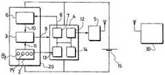
- FIG. 1illustrates a functional block diagram of the first embodiment of the pressure sensor and of the microprocessor of the invention
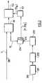
- FIG. 2illustrates a simplified block diagram of vehicle and wheel assembly lines on which sensors such as that of FIG. 1 are assembled and
- FIG. 3illustrates a diagram of a part of the functional blocks of the second embodiment of the pressure sensor and of the microprocessor of the invention.
- the tire pressure sensor 20is associated with a power-supply battery 15 , a measuring microprocessor 4 , also powered by the battery 15 and able to take, by means of a polling function 13 , and to process, by means of a monitor 12 , measurements of physical variables including the pressure of the tire Pr, the operating temperature .theta..sub.f and other indicative parameters relating to the rotation of the wheel, for example the speed of rotation V.sub.r or the centrifugal force F.sub.r.
- These physical variablesare sensed by an assembly 2 of microsensors, respectively manometric membrane, thermistor, microgyroscope or microaccelerometer or rolling switch.
- the monitor 12 of the microprocessor 4controls a radio transmission circuit 5 to communicate, to the vehicle's on-board computer 30 , in operating time, the identification ID of the sensor, the measurements collected and possibly certain results of the processing carried out, these data being organized in a predetermined frame in order to be transmitted.
- An activation module 3 in the pressure sensor 20 connected to the microprocessor 4 by a connection 9initiates operation of this microprocessor in a cyclical manner with a period T imposed by an activation control timer 6 mounted in the sensor 20 connected to the activation module 3 by a connection 10 .
- the period Tis calculated by a timing function 7 of the microprocessor 4 in order to program the timer 6 via a connection 8 .
- the function 7forms part of the microprocessor 4 .
- the activation module 3also receives information on the pressure and/or rotation of the wheel from the microsensor assembly 2 .
- the timing function 7receives the values of the physical variables it requires to calculate the period T to be imposed on the activation module.
- the vehicle assembly line 100includes the vehicle of the number or row V of the line.
- the processpasses to an inflation step 203 and a wheel-balancing step 204 .
- These operationsare very quick.
- the balancingonly takes a few seconds.
- the number Pi of the wheel and the identification number IDp of the wheel pressure sensorare sensed, this latter being sensed by a receiver 214 in the manner explained below.
- These two parametersare transmitted to a diagnostic station 103 which registers that the wheel Pi is fitted with a pressure sensor with the identification IDp.
- the battery 15powers the electronic elements but they are in a so-called storage mode and the current consumed is very low (less than 100 nA).
- the sensoractivates the microprocessor after a specific period in order for it to read the pressure value, validate the mode and return to the dormant mode.
- the transmission circuitis always in dormant mode.
- Storage modeis maintained as long as the microprocessor 4 does not detect a pressure difference.
- a pressure microsensortypically a manometric membrane of the assembly 2 , if the pressure exceeds a certain threshold (in this case 0.7 bar) there is a transition from the storage mode to the parking mode and the system becomes active.
- a certain thresholdin this case 0.7 bar
- the activation periodcan be, for example, one hour.
- driving moderoad
- the periodcan be one minute.
- the predetermined step of the wheel assembly linewhich is of relevance in this case can be the step 203 for pressurizing the tire (inflation) or preferably the wheel-balancing step 204 .
- the activation periodcan be very short (for example 1 s).
- the information from the pressure microsensor Pr (manometric membrane) or rotation microsensor (microgryo) Vr or even the centrifugal force sensor Fr (rolling switch, microaccelerometer)is transmitted to the activation module 3 by the connection 11 from the microsensor assembly 2 , which causes the microprocessor 4 to be activated via the connection 9 .
- the connections 8 , 9 , 10may conform to the protocol SPI (Synchronous Protocol Interface).
- the monitor 12 of the microprocessorinitiates the polling function 13 and receives the measurements P.sub.r, .theta..sub.f, V.sub.r therefrom which it transmits to the timing function 7 in order to program the timer 6 .
- the timing function 7checks the content of the memory 14 . If this content corresponds to its storage mode then assembly is taking place and the timing function 7 communicates to the timer 6 a period T 1 of transmission of the predetermined frame containing, in particular, the identification number ID of the sensor compatible with the assembly rate of the assembly lines, stores in memory 14 the new state of operation of the sensor corresponding to the assembly phase, then returns the microprocessor 4 to its dormant state.
- the timer 6subsequently activates the activation module 3 in the period T 1 in order to activate the microprocessor 4 which, taking account of the state of the memory 14 and by means of the monitor 12 , controls the transmission circuit 5 to transmit the predetermined frame, then returns to its dormant state.
- the period T.sub. 1is very short, of the order of a few tens of seconds, and the corresponding frames 204 are, for example, transmitted during the period covering the time in which the wheel balancing step is carried out on the wheel assembly line, so as to avoid any ambiguity with the wheels which precede or follow in the assembly line.
- a radio receiver 214is provided receiving the predetermined frame transmitted by the pressure sensor of the wheel P and containing, in particular, the identification IDp of the said sensor.
- the radio receiver 214produces a message containing the data P and IDp which it communicates to the diagnostic station 103 responsible for teaching the on-board computer of the vehicles of row V on the vehicle assembly line 100 .
- the diagnostic station 103For each vehicle V the diagnostic station 103 deduces which wheels P are to be fitted to it, for example, by the formulae (2) and to which location L these wheels P of sensor IDp are allocated, for example, by the formulae (1).
- the radio receiver 214initializes the diagnostic station 103 which will program the on-board computer of the vehicle V when this vehicle is at the teaching station 102 .
- the interval from the time of transmission of the frame to the period T 1can be determined by detecting the rotation of the wheel by the assembly 2 .
- the pressure sensoris then placed in its parking mode by the microprocessor 4 , the timer being adjusted to a period T 2 of about one hour.
- this parking modeis interrupted when the wheel is caused to rotate again, the process remains the same but the state of the memory 14 shows that assembly is no longer taking place and the timing function 7 calculates a period T 2 which this time is not a predetermined period but which depends on measurements collected by the polling function 13 , principally the temperature ⁇ f of the tire.
- the period T 2can be changed to close to 2000 seconds. It will be clear that the temperature may fall again during this time. For this reason it may be advantageous to activate the microprocessor prematurely and to activate the timing function 7 in order to modify the activation period.
- the activation module 3is sensitive to a gradient in the temperature ⁇ f by the connection 11 and activates the microprocessor 4 if the temperature ⁇ f varies by a certain percentage in the duration of a period T 2 .
- activation control timer 6was located in the pressure sensor, outside the microprocessor 4 , and could be programmed by the microprocessor 4 , the activation module 3 being controlled by the programmable timer 6 to periodically activate the microprocessor following a variable period.
- the activation module 3 ′in this case has a fixed period T (for example, one second).
- the activation control timer 6 ′is located inside the microprocessor 4 . It is still a timer which can be programmed by the timing function 7 of the microprocessor but it is the activation module 3 ′ which controls it in order that, via its output 61 , it periodically activates the microprocessor 4 following a variable period P, being variable, for example, from 1 second to 2000 seconds, or 65536 seconds, if it is a 2 16 bit timer.
- the pressure sensorwill increment the timer 6 ′ by one unit for each second and, if the timing function 7 has been “programmed to 8” for example, the activation of the microprocessor will take place every eight seconds, i.e. every eight pulses of the activation module.
- the timer 6 ′in this case acts as a frequency divider (period multiplier).
- microsensors 2are not connected to the activation module 3 ′.
Landscapes
- Engineering & Computer Science (AREA)
- Mechanical Engineering (AREA)
- Computer Networks & Wireless Communication (AREA)
- Arrangements For Transmission Of Measured Signals (AREA)
- Measuring Fluid Pressure (AREA)
Abstract
Description
Po=5×V−4
the integer i being an indicator of the location L of the wheel Po+i on the vehicle V.
Claims (17)
Applications Claiming Priority (3)
| Application Number | Priority Date | Filing Date | Title |
|---|---|---|---|
| FR0202201AFR2836222B1 (en) | 2002-02-21 | 2002-02-21 | PRESSURE SENSOR ASSEMBLY WITH WAKE-UP MODULE AND MEASUREMENT AND CONTROL MICROPROCESSOR |
| FR02/02201 | 2002-02-21 | ||
| PCT/FR2003/000571WO2003070495A2 (en) | 2002-02-21 | 2003-02-20 | Pressure sensor assembly with clock module and measuring and monitoring microprocessor |
Publications (2)
| Publication Number | Publication Date |
|---|---|
| US20050206512A1 US20050206512A1 (en) | 2005-09-22 |
| US7437921B2true US7437921B2 (en) | 2008-10-21 |
Family
ID=27636382
Family Applications (1)
| Application Number | Title | Priority Date | Filing Date |
|---|---|---|---|
| US10/505,340Expired - Fee RelatedUS7437921B2 (en) | 2002-02-21 | 2003-02-20 | Assembly including a pressure sensor, with an activation module, and a microprocessor for measurement and control purposes |
Country Status (5)
| Country | Link |
|---|---|
| US (1) | US7437921B2 (en) |
| EP (1) | EP1478525B1 (en) |
| ES (1) | ES2436505T3 (en) |
| FR (1) | FR2836222B1 (en) |
| WO (1) | WO2003070495A2 (en) |
Cited By (3)
| Publication number | Priority date | Publication date | Assignee | Title |
|---|---|---|---|---|
| US20070205883A1 (en)* | 2006-03-02 | 2007-09-06 | Denso Corporation | Tire inflation pressure detecting apparatus with function of identifying running and spare wheels |
| US20150128691A1 (en)* | 2013-11-12 | 2015-05-14 | Goodrich Corporation | Tire Pressure Observation After Detecting Abnormal Pressure Condition |
| US9387732B1 (en) | 2009-08-05 | 2016-07-12 | Honda Motor Co., Ltd. | Tire pressure monitoring system (TPMS) activation method |
Families Citing this family (5)
| Publication number | Priority date | Publication date | Assignee | Title |
|---|---|---|---|---|
| DE102007010888B4 (en)* | 2007-03-06 | 2010-03-04 | Continental Automotive Gmbh | Control unit for wireless communication with a peripheral unit |
| DE102007049360A1 (en)* | 2007-10-15 | 2009-04-16 | Robert Bosch Gmbh | A method of operating a tire pressure monitoring system and a tire pressure monitoring system |
| US10105997B2 (en)* | 2015-12-21 | 2018-10-23 | The Goodyear Tire & Rubber Company | Integrated TPMS module and RFID tag data sharing system in a tire |
| CN106585296A (en)* | 2016-12-09 | 2017-04-26 | 深圳市元征科技股份有限公司 | Activating method and system for vehicle tire pressure sensor |
| CN111896149A (en)* | 2020-09-09 | 2020-11-06 | 河南四季竹信息科技有限公司 | Spring Dynamometer and Spring Dynamometer Teaching Data Acquisition System |
Citations (8)
| Publication number | Priority date | Publication date | Assignee | Title |
|---|---|---|---|---|
| US5656993A (en) | 1995-05-08 | 1997-08-12 | Semisystems, Inc. | Vehicle wheel condition monitor and data storage system |
| US5783992A (en) | 1996-07-22 | 1998-07-21 | Delco Electronics Corp. | Time based low tire pressure warning sensor |
| US6271748B1 (en)* | 1994-08-31 | 2001-08-07 | Andrew John Derbyshire | Tyre condition monitoring system |
| US20030102966A1 (en)* | 1997-01-15 | 2003-06-05 | Boris Konchin | Tire pressure sensing system |
| US6619110B1 (en)* | 1998-12-11 | 2003-09-16 | Johnson Controls Automotive Electronics | Module for measuring tire pressure |
| US6684691B1 (en)* | 2000-09-19 | 2004-02-03 | General Motors Corporation | Method and system for determining tire pressure imbalances |
| US7076999B1 (en)* | 2001-01-11 | 2006-07-18 | Lewis Lee Knox | Tire pressure monitoring system |
| US20060180647A1 (en)* | 2005-02-11 | 2006-08-17 | Hansen Scott R | RFID applications |
Family Cites Families (1)
| Publication number | Priority date | Publication date | Assignee | Title |
|---|---|---|---|---|
| GB9220234D0 (en)* | 1992-09-24 | 1992-11-04 | Otter Controls Ltd | Tyre condition monitoring |
- 2002
- 2002-02-21FRFR0202201Apatent/FR2836222B1/ennot_activeExpired - Fee Related
- 2003
- 2003-02-20USUS10/505,340patent/US7437921B2/ennot_activeExpired - Fee Related
- 2003-02-20ESES03718904.0Tpatent/ES2436505T3/ennot_activeExpired - Lifetime
- 2003-02-20EPEP03718904.0Apatent/EP1478525B1/ennot_activeExpired - Lifetime
- 2003-02-20WOPCT/FR2003/000571patent/WO2003070495A2/ennot_activeApplication Discontinuation
Patent Citations (10)
| Publication number | Priority date | Publication date | Assignee | Title |
|---|---|---|---|---|
| US6271748B1 (en)* | 1994-08-31 | 2001-08-07 | Andrew John Derbyshire | Tyre condition monitoring system |
| US20020044050A1 (en)* | 1994-08-31 | 2002-04-18 | Derbyshire Andrew John | Tyre condition monitoring system |
| US6545599B2 (en)* | 1994-08-31 | 2003-04-08 | Andrew John Derbyshire | Tire condition monitoring system |
| US5656993A (en) | 1995-05-08 | 1997-08-12 | Semisystems, Inc. | Vehicle wheel condition monitor and data storage system |
| US5783992A (en) | 1996-07-22 | 1998-07-21 | Delco Electronics Corp. | Time based low tire pressure warning sensor |
| US20030102966A1 (en)* | 1997-01-15 | 2003-06-05 | Boris Konchin | Tire pressure sensing system |
| US6619110B1 (en)* | 1998-12-11 | 2003-09-16 | Johnson Controls Automotive Electronics | Module for measuring tire pressure |
| US6684691B1 (en)* | 2000-09-19 | 2004-02-03 | General Motors Corporation | Method and system for determining tire pressure imbalances |
| US7076999B1 (en)* | 2001-01-11 | 2006-07-18 | Lewis Lee Knox | Tire pressure monitoring system |
| US20060180647A1 (en)* | 2005-02-11 | 2006-08-17 | Hansen Scott R | RFID applications |
Cited By (5)
| Publication number | Priority date | Publication date | Assignee | Title |
|---|---|---|---|---|
| US20070205883A1 (en)* | 2006-03-02 | 2007-09-06 | Denso Corporation | Tire inflation pressure detecting apparatus with function of identifying running and spare wheels |
| US7696861B2 (en)* | 2006-03-02 | 2010-04-13 | Denso Corporation | Tire inflation pressure detecting apparatus with function of identifying running and spare wheels |
| US9387732B1 (en) | 2009-08-05 | 2016-07-12 | Honda Motor Co., Ltd. | Tire pressure monitoring system (TPMS) activation method |
| US20150128691A1 (en)* | 2013-11-12 | 2015-05-14 | Goodrich Corporation | Tire Pressure Observation After Detecting Abnormal Pressure Condition |
| US9057661B2 (en)* | 2013-11-12 | 2015-06-16 | Goodrich Corporation | Tire pressure observation after detecting abnormal pressure condition |
Also Published As
| Publication number | Publication date |
|---|---|
| EP1478525B1 (en) | 2013-09-25 |
| FR2836222A1 (en) | 2003-08-22 |
| US20050206512A1 (en) | 2005-09-22 |
| FR2836222B1 (en) | 2004-04-30 |
| EP1478525A2 (en) | 2004-11-24 |
| WO2003070495A2 (en) | 2003-08-28 |
| ES2436505T3 (en) | 2014-01-02 |
| WO2003070495A3 (en) | 2003-11-13 |
Similar Documents
| Publication | Publication Date | Title |
|---|---|---|
| EP1110764B1 (en) | Apparatus and method for sensing a condition of a vehicle tire | |
| CN100592046C (en) | Tire pressure monitor with the ability to accurately detect the state of vehicle motion | |
| US6232875B1 (en) | Apparatus and method for controlling a tire condition module of a vehicle tire | |
| JP5041005B2 (en) | Tire pressure monitoring device | |
| US7391308B2 (en) | Monitoring device, transceiver system and its control method | |
| US5783992A (en) | Time based low tire pressure warning sensor | |
| EP1092570B1 (en) | Transmitter and transmitting method of tire air pressure monitoring apparatus | |
| EP1556234B1 (en) | Apparatus and method for power management in a tire pressure monitoring system | |
| CA2473492C (en) | Method for monitoring the pressure in pneumatic tires on vehicles | |
| EP0662050B1 (en) | Tyre condition monitoring | |
| US6938467B2 (en) | Transmitter of tire condition monitoring apparatus | |
| US20030156022A1 (en) | Transmitter of tire condition monitoring apparatus and tire condition monitoring apparatus | |
| US10093139B2 (en) | Tire-pressure sensor unit, a tire-pressure notification device, and vehicle | |
| US20020075146A1 (en) | Transmitter and transmitting method of tire condition monitoring apparatus | |
| US7437921B2 (en) | Assembly including a pressure sensor, with an activation module, and a microprocessor for measurement and control purposes | |
| JP2004314727A (en) | Wheel information acquisition system | |
| JP3951947B2 (en) | Tire pressure detector | |
| US20060041344A1 (en) | Monitoring apparatus and method for handling detected results of a monitored object | |
| EP1856330B1 (en) | System for detecting motion of an object | |
| JP2000203219A (en) | Tire condition monitoring unit | |
| JP2006321263A (en) | Wheel information processing device |
Legal Events
| Date | Code | Title | Description |
|---|---|---|---|
| AS | Assignment | Owner name:JOHNSON CONTROLS AUTOMOTIVE ELECTRONICS, FRANCE Free format text:ASSIGNMENT OF ASSIGNORS INTEREST;ASSIGNOR:DELAPORTE, FRANCIS;REEL/FRAME:015157/0010 Effective date:20040906 | |
| STCF | Information on status: patent grant | Free format text:PATENTED CASE | |
| FEPP | Fee payment procedure | Free format text:PAYOR NUMBER ASSIGNED (ORIGINAL EVENT CODE: ASPN); ENTITY STATUS OF PATENT OWNER: LARGE ENTITY | |
| FPAY | Fee payment | Year of fee payment:4 | |
| AS | Assignment | Owner name:JOHNSON CONTROLS TECHNOLOGY COMPANY, MICHIGAN Free format text:ASSIGNMENT OF ASSIGNORS INTEREST;ASSIGNOR:JOHNSON CONTROLS AUTOMOTIVE ELECTRONICS;REEL/FRAME:031691/0699 Effective date:20131128 | |
| AS | Assignment | Owner name:VISTEON GLOBAL TECHNOLOGIES, INC., MICHIGAN Free format text:ASSIGNMENT OF ASSIGNORS INTEREST;ASSIGNOR:JOHNSON CONTROLS TECHNOLOGY COMPANY;REEL/FRAME:035091/0435 Effective date:20140701 | |
| FPAY | Fee payment | Year of fee payment:8 | |
| SULP | Surcharge for late payment | Year of fee payment:7 | |
| FEPP | Fee payment procedure | Free format text:MAINTENANCE FEE REMINDER MAILED (ORIGINAL EVENT CODE: REM.); ENTITY STATUS OF PATENT OWNER: LARGE ENTITY | |
| LAPS | Lapse for failure to pay maintenance fees | Free format text:PATENT EXPIRED FOR FAILURE TO PAY MAINTENANCE FEES (ORIGINAL EVENT CODE: EXP.); ENTITY STATUS OF PATENT OWNER: LARGE ENTITY | |
| STCH | Information on status: patent discontinuation | Free format text:PATENT EXPIRED DUE TO NONPAYMENT OF MAINTENANCE FEES UNDER 37 CFR 1.362 | |
| FP | Lapsed due to failure to pay maintenance fee | Effective date:20201021 |