US7437676B1 - Methods and apparatus for managing network resources via use of a relationship view - Google Patents
Methods and apparatus for managing network resources via use of a relationship viewDownload PDFInfo
- Publication number
- US7437676B1 US7437676B1US10/675,586US67558603AUS7437676B1US 7437676 B1US7437676 B1US 7437676B1US 67558603 AUS67558603 AUS 67558603AUS 7437676 B1US7437676 B1US 7437676B1
- Authority
- US
- United States
- Prior art keywords
- column
- icons
- icon
- managed
- relationship
- Prior art date
- Legal status (The legal status is an assumption and is not a legal conclusion. Google has not performed a legal analysis and makes no representation as to the accuracy of the status listed.)
- Expired - Lifetime, expires
Links
Images


Classifications
- H—ELECTRICITY
- H04—ELECTRIC COMMUNICATION TECHNIQUE
- H04L—TRANSMISSION OF DIGITAL INFORMATION, e.g. TELEGRAPHIC COMMUNICATION
- H04L41/00—Arrangements for maintenance, administration or management of data switching networks, e.g. of packet switching networks
- H04L41/22—Arrangements for maintenance, administration or management of data switching networks, e.g. of packet switching networks comprising specially adapted graphical user interfaces [GUI]
- G—PHYSICS
- G06—COMPUTING OR CALCULATING; COUNTING
- G06F—ELECTRIC DIGITAL DATA PROCESSING
- G06F3/00—Input arrangements for transferring data to be processed into a form capable of being handled by the computer; Output arrangements for transferring data from processing unit to output unit, e.g. interface arrangements
- G06F3/06—Digital input from, or digital output to, record carriers, e.g. RAID, emulated record carriers or networked record carriers
- G06F3/0601—Interfaces specially adapted for storage systems
- G06F3/0602—Interfaces specially adapted for storage systems specifically adapted to achieve a particular effect
- G06F3/0604—Improving or facilitating administration, e.g. storage management
- G06F3/0605—Improving or facilitating administration, e.g. storage management by facilitating the interaction with a user or administrator
- G—PHYSICS
- G06—COMPUTING OR CALCULATING; COUNTING
- G06F—ELECTRIC DIGITAL DATA PROCESSING
- G06F3/00—Input arrangements for transferring data to be processed into a form capable of being handled by the computer; Output arrangements for transferring data from processing unit to output unit, e.g. interface arrangements
- G06F3/06—Digital input from, or digital output to, record carriers, e.g. RAID, emulated record carriers or networked record carriers
- G06F3/0601—Interfaces specially adapted for storage systems
- G06F3/0628—Interfaces specially adapted for storage systems making use of a particular technique
- G06F3/0655—Vertical data movement, i.e. input-output transfer; data movement between one or more hosts and one or more storage devices
- G—PHYSICS
- G06—COMPUTING OR CALCULATING; COUNTING
- G06F—ELECTRIC DIGITAL DATA PROCESSING
- G06F3/00—Input arrangements for transferring data to be processed into a form capable of being handled by the computer; Output arrangements for transferring data from processing unit to output unit, e.g. interface arrangements
- G06F3/06—Digital input from, or digital output to, record carriers, e.g. RAID, emulated record carriers or networked record carriers
- G06F3/0601—Interfaces specially adapted for storage systems
- G06F3/0668—Interfaces specially adapted for storage systems adopting a particular infrastructure
- G06F3/067—Distributed or networked storage systems, e.g. storage area networks [SAN], network attached storage [NAS]
- H—ELECTRICITY
- H04—ELECTRIC COMMUNICATION TECHNIQUE
- H04L—TRANSMISSION OF DIGITAL INFORMATION, e.g. TELEGRAPHIC COMMUNICATION
- H04L41/00—Arrangements for maintenance, administration or management of data switching networks, e.g. of packet switching networks
- H04L41/02—Standardisation; Integration
- H04L41/024—Standardisation; Integration using relational databases for representation of network management data, e.g. managing via structured query language [SQL]
- G—PHYSICS
- G06—COMPUTING OR CALCULATING; COUNTING
- G06F—ELECTRIC DIGITAL DATA PROCESSING
- G06F2206/00—Indexing scheme related to dedicated interfaces for computers
- G06F2206/10—Indexing scheme related to storage interfaces for computers, indexing schema related to group G06F3/06
- G06F2206/1008—Graphical user interface [GUI]
- G—PHYSICS
- G06—COMPUTING OR CALCULATING; COUNTING
- G06F—ELECTRIC DIGITAL DATA PROCESSING
- G06F3/00—Input arrangements for transferring data to be processed into a form capable of being handled by the computer; Output arrangements for transferring data from processing unit to output unit, e.g. interface arrangements
- G06F3/06—Digital input from, or digital output to, record carriers, e.g. RAID, emulated record carriers or networked record carriers
- G06F3/0601—Interfaces specially adapted for storage systems
- H—ELECTRICITY
- H04—ELECTRIC COMMUNICATION TECHNIQUE
- H04L—TRANSMISSION OF DIGITAL INFORMATION, e.g. TELEGRAPHIC COMMUNICATION
- H04L67/00—Network arrangements or protocols for supporting network services or applications
- H04L67/01—Protocols
- H04L67/10—Protocols in which an application is distributed across nodes in the network
- H04L67/1097—Protocols in which an application is distributed across nodes in the network for distributed storage of data in networks, e.g. transport arrangements for network file system [NFS], storage area networks [SAN] or network attached storage [NAS]
Definitions
- GUIGraphical User Interfaces
- a network management applicationrendering the graphical user interface enables the network manager to graphically select, interact with, and manage local or remote devices and associated software processes operating in the storage area network. More specifically, based on use of the graphical user interface in combination with an input device such as a hand operated mouse and corresponding pointer displayed on a viewing screen, a network manager is able to manage hardware and software entities such as file systems, databases, storage devices, peripherals, network data communications devices, etc. associated with the storage area network. Typically, in such network management applications, the network manager selects a displayed icon representing a corresponding resource in the network and applies management commands to a selected icon to carry out intended management functions.
- GUIGraphical User Interfaces
- a networkmay include a number of hardware devices such as servers, data communications devices (e.g., switches, routers, etc.), network attached storage devices, proxy devices, firewall devices, and so forth that are coupled amongst each other via physical cables.
- a conventional management applicationtypically provides access to a database that contains data structures describing and defining how these hardware resources are interconnected with each other within the network. The management application uses this information in the database to render a graphical display of the networked devices as individual icons coupled to each other with lines that represent physical data communications links.
- userstypically have a limited ability to visually scan, identify, select and then apply management display commands to specific manageable network resources of interest using conventional network views and supported display functions. That is, conventional relationship views of managed entities render it difficult (e.g., sometimes due to high density of icons and corresponding relationships) for a user to identify and then select particular managed resources of interest in a network due to the complex graphical layouts that such conventional applications provide. Furthermore, conventional applications fail to support user friendly management display functions to manage entities that enhance a GUIs usefulness.
- Embodiments of the inventionsignificantly overcome the aforementioned and other deficiencies of conventional network display and management systems.
- the computer devicemay be, for example, a network management workstation that supports embodiments of the invention includes a management software application that presents, during runtime, a graphical user interface including a relationship view (i.e., a visual representation of various elements in a SAN represented by icons and other relationship symbols) of managed entities associated with a network such as a storage area network. Relationship views may be presented to a user such as a network manager to convey relationships among software and hardware entities of the storage area network.
- Certain embodiments of the inventioninclude network management software incorporating the functionality explained herein, as well as computerized devices configured to operate as explained herein.
- a processing devicegenerates a relationship view including managed entities associated with a storage area network based on objects stored in a relational database.
- a management databasetracks relationships among the managed entities (e.g., hardware and software entities such as host servers, storage devices, file systems, databases, volumes, etc.) via use of corresponding managed objects.
- Each managed entity in the storage area networkmay have a corresponding managed object stored in the relational database.
- managed objects of a particular typeare categorized into one or more tables.
- the tablesare related to one another by foreign key attributes (e.g., references), which represent or identify relationships between types of managed objects (and thus a relationship between corresponding managed entities).
- Relationships between the managed objects in the relational databasemay be generally classified as either association or containment.
- Associationidentifies a logical relationship between managed objects.
- Containmentidentifies one or more objects that form a logical grouping. For example, containment (e.g., parent-child relationship) may identify a set of similar types of managed entities such as a group of databases. Also, containment may identify that a group of certain hardware and/or software entities are associated with, for example, a particular managed entity such as a host server device.
- icons displayed in a relationship viewdepict corresponding managed entities of a storage area network.
- associationse.g., relationships
- relationship pathssuch as lines extending between icons.
- Containment in a relationship viewmay be depicted as a single box or nested sets of boxes encompassing a group or groups of displayed icons representing a logical grouping of related managed entities (displayed as icons) in the storage area network.
- a box or containermay represent a computer device such as a host server (e.g., a managed entity) of a storage area network; the corresponding icons in the box or container may represent other managed entities (e.g., databases, file systems, volumes, groups of volumes, host devices, etc.) contained in or associated with the host server.
- a host servere.g., a managed entity
- the corresponding icons in the box or containermay represent other managed entities (e.g., databases, file systems, volumes, groups of volumes, host devices, etc.) contained in or associated with the host server.
- activating an expand function associated with an icon displayed in a relationship viewresults in an expansion of that relationship view.
- An expanded relationship viewmay include more specific details such as additional relationships between newly displayed icons (e.g., related but previously hidden managed entities) associated with the expanded icon and corresponding previously displayed neighboring icons.
- a usermay click on an icon representing a database in a relationship view to display otherwise hidden details associated with the corresponding database.
- a usermay choose to expand a relationship view or, more particularly, a database icon (representing a corresponding database in the managed network) so that the relationship view further includes detailed relationship paths between a database schema, table space and database files (all of which are sub-details of the database icon) instead of merely displaying a high level relationship between a single database icon associated with a host server of the storage area network and a corresponding storage disk of the storage area network.
- a processing devicemay receive an identity of a selected managed entity (e.g., a managed entity such as a hardware or software entity selected by a user such as a network manager) existing in a storage area network for which the user would like to view related managed entities in a relationship view.
- a selected managed entitye.g., a managed entity such as a hardware or software entity selected by a user such as a network manager
- the processing deviceretrieves a first managed object from a management database that corresponds to the selected managed entity.
- the databasealso includes managed objects associated with other managed entities in the network. Based on processing of information in the first managed object and retrieval and processing of other related managed objects in the management database, the processing device identifies a sequence of relationships between the selected managed entity and other managed entities in the storage area network.
- Identification of the sequence of relationships (or a portion thereof) between the selected managed entity and other managed entitiesenables the processing device to generate and graphically display a relationship view of the selected managed entity and at least one other managed entity of the storage area network based on use of columns of icons.
- a first column in the relationship viewmay include at least one icon graphically representing a managed host entity.
- a second column of the relationship viewmay include at least one icon graphically representing a managed storage entity.
- At least a portion of the sequence of relationships between the managed entitiesare graphically represented by relationship paths between the at least one icon in the first column and the at least one icon in the second column.
- the processing devicemaintains a management database of objects identifying relationships between the managed entities via collection of information (e.g., configuration information, connectivity information, etc.) from agents distributed throughout the storage area network. Based on receipt of configuration data (such as logical association information) from the agents, the management database may be updated at least occasionally to reflect relationships between previously existing and newly created hardware and software type entities associated with the storage area network.
- informatione.g., configuration information, connectivity information, etc.
- the management databasemay be updated at least occasionally to reflect relationships between previously existing and newly created hardware and software type entities associated with the storage area network.
- One purpose of tracking the relationships, as discussed,is to support generation of relationship views of managed entities in a storage area network.
- Selection of which managed entity to display in the relationship viewmay depend on input from a user such as a network manager overseeing a corresponding storage area network.
- a vertical hierarchy of managed entitiese.g., s logical hierarchy of databases, file systems, volumes, ports, storage devices, etc.
- the viewere.g., a network manager
- the processing device associated with the GUIIn response to detecting selection of a particular entry (e.g., a managed entity) listed in the vertical hierarchy, the processing device associated with the GUI generates the first relationship view from the perspective of the selected managed entity.
- the processing devicegenerates a relationship view by first receiving an identity of the selected managed entity existing in the storage area network.
- the processing deviceretrieves a managed object from the management database that corresponds to the selected managed entity.
- the processing deviceidentifies and retrieves objects related to the retrieved managed object associated with the selected managed entity for storage in data structures.
- the processing deviceBased on processing of the data structures and, more specifically, references such as foreign keys associated with the managed object, the processing device identifies (a sequence of) relationships between the selected managed entity and other managed entities in the network.
- a first managed objectcorresponding to the selected managed entity
- the second managed objectmay include a reference to a third managed entity, and so on.
- the referencesrepresent a sequence of relationships between the managed objects and corresponding managed entities.
- the processing deviceutilizes information such as references in a managed object associated with a host server (i.e., a managed entity) to identify one or multiple corresponding databases (i.e., another managed entity and object) associated with the host server.
- a managed object associated with a host serveri.e., a managed entity
- one or multiple corresponding databasesi.e., another managed entity and object
- managed objects associated with the one or multiple corresponding databasesmay include further references (e.g., foreign keys) to identify sub-parts of the database.
- identification of a sequence of relationships between managed entitiesenables the processing device to generate and graphically display a relationship view of the selected managed entity and at least one other managed entity of the storage area network based on use of columns of icons and corresponding relationship paths.
- a first column in a relationship viewmay include at least one icon graphically representing a managed software entity.
- a second column of the relationship viewmay include at least one icon graphically representing a managed storage entity.
- the processing devicedisplays at least a portion of the sequence of relationships between managed entities via relationship paths between the at least one icon in the first column and the at least one icon in the second column.
- the processing devicegenerates a horizontally disposed relationship view of adjacently positioned columns including multiple icons and corresponding relationship paths from the perspective of an icon associated with the selected managed entity.
- Presenting adjacent columns of iconsenables the viewer to quickly identify a group of similar types of managed entities in the storage area network.
- Presenting relationship paths between the icons spanning from, for example, an icon representing a software entity (such as a DB schema) to a hardware entity (such as a corresponding storage device)enables the viewer of the relationship view to easily identify managed entities related to the selected managed entity.
- a relationship viewmay include a container (e.g., a graphical box) encompassing one or multiple icons (or even other containers) to represent another managed entity associated with the storage area network.
- a containermay represent a managed entity such as a database, a group of volumes, a host server, a storage disk, etc.
- Use of one or multiple containers (or nested containers) in the relationship view along with icons and relationship pathsenables the viewer to quickly identify that a group of icons is associated with a particular volume, database, host server, etc.
- One display mode associated with a relationship viewinvolves use of a viewer controlled device (such as a computer mouse) to highlight relationship paths displayed in a corresponding relationship view between icons representing managed entities.
- the viewer controlled devicesupports movement of a corresponding cursor (such as an arrow icon) on the display screen.
- the processing devicehighlights (bolds, changes color, distinguishes, . . . ) the given relationship path over others also displayed on a display screen.
- This featuremay be extended to highlight icons, containers and other managed entities displayed in the relationship view when a use clicks on such symbols. Consequently, a viewer may easily identify icons at either ends of the highlighted relationship path even in the presence of many densely displayed relationship paths between other neighboring displayed icons.
- another display mode supported by an embodiment of the inventionenables a viewer to expand or collapse an icon in a corresponding relationship view.
- a visual regionmay be allocated in relation to a corresponding icon to receive input commands such as expand or collapse generated by a user.
- the processing deviceexpands the first relationship view of managed entities in the storage area network into a second relationship view. For example, if a first relationship view includes a first and second column of icons, an expanded relationship view may include additional icons representing other managed entities of the storage area network associated with the expanded managed entity.
- the processing devicecollapses (hides) a view of certain icons associated with the relationship view. Accordingly, a user may select a level of detail associated with a relationship view.
- one embodiment of the inventionsupports a zoom in and zoom out function in the relationship view.
- the processing devicemay display a first relationship view having a level of detail as selected by a given viewer. From the first relationship view, a user may select a particular icon among many displayed icons and corresponding relationship paths. In response to detecting the user's selection of the particular icon in the first area, the processing device generates a second relationship view in a second area of the display screen.
- the second relationship viewincludes a presentation of relationships between a managed entity associated with the particular icon and other associated nearest neighboring managed entities in the storage area network.
- This display management functionenables a user to duplicate a relationship view for the selected entity apart from other unwanted relationship information in the first view.
- the processing devicegenerates a second relationship view in response to a user dragging and dropping the particular icon from a first area of the display screen to a second area of a display screen.
- the computerized deviceincludes a display, a memory system, a processor (e.g., a processing device) and an interconnect.
- the interconnectsupports communications among the display, the processor and the memory system.
- the memory systemis encoded with a resource management application that, when executed on the processor, produces a resource management process that includes a graphical user interface produced on the display of the computerized device.
- the graphical user interfaceallows the resource management process to perform all of the method embodiments and operations explained herein as embodiment of the invention.
- a computer program producte.g., a computer-readable medium
- computer program logicencoded thereon may be executed on a computerized device to support generation and display of relationship views and associated operations as explained herein.
- the computer program logicwhen executed on at least one processor with a computing system, causes the processor to perform the operations (e.g., the methods) indicated herein as embodiments of the invention.
- Such arrangements of the inventionare typically provided as software, code and/or other data structures arranged or encoded on a computer readable medium such as an optical medium (e.g., CD-ROM), floppy or hard disk or other a medium such as firmware or microcode in one or more ROM or RAM or PROM chips or as an Application Specific Integrated Circuit (ASIC) or as downloadable software images in one or more modules, shared libraries, etc.
- a computer readable mediumsuch as an optical medium (e.g., CD-ROM), floppy or hard disk or other a medium such as firmware or microcode in one or more ROM or RAM or PROM chips or as an Application Specific Integrated Circuit (ASIC) or as downloadable software images in one or more modules, shared libraries, etc.
- ASICApplication Specific Integrated Circuit
- the software or firmware or other such configurationscan be installed onto a computerized device to cause one or more processors in the computerized device to perform the techniques explained herein as embodiments of the invention.
- system of the inventioncan be embodied as a software program or as a software program operating in conjunction with corresponding hardware.
- Example embodiments of the inventionmay be implemented within EMC's Control Center (ECC) software application that provides graphical management functionality for storage area network resources and in computerized devices that operate the Control Center (ECC) software.
- EMCControl Center
- Control Center softwareis manufactured by EMC Corporation of Hopkinton, Mass., USA.
- FIG. 1is a pictorial diagram of a storage area network and management station configured to operate according to an embodiment of the invention.
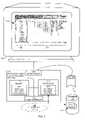
- FIG. 2is a block diagram of a sample architecture associated with the management station in FIG. 1 including a graphical user interface generated according to an embodiment of the invention.
- FIG. 3is a flowchart for generating a relationship view according to an embodiment of the invention.
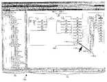
- FIG. 4is a screenshot of a relationship view and vertical hierarchy of icons according to an embodiment of the invention.
- FIGS. 5 and 6combine to form a flowchart illustrating a more detailed technique for generating a relationship view according to an embodiment of the invention.
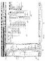
- FIG. 7is a screenshot of a display screen prior to selection of a managed entity according to an embodiment of the invention.
- FIG. 8is a screenshot of an expanded relationship view after selection of a managed entity according to an embodiment of the invention.
- FIG. 9is a flowchart illustrating a technique for expanding and collapsing icons in a relationship view according to an embodiment of the invention.
- FIG. 10is a flowchart illustrating a technique for highlighting a relationship path according to an embodiment of the invention.
- FIG. 11is a screenshot including a relationship view in which a relationship path selected by the a viewer is highlighted according to an embodiment of the invention.
- FIG. 12is a flowchart illustrating a technique for expanding a display screen to include multiple relationship views according to an embodiment of the invention.
- FIG. 13is a screenshot of a display screen including multiple relationship views according to an embodiment of the invention.
- Embodiments of the inventioninclude a processing device that generates a relationship view including managed entities associated with a storage area network based on corresponding objects stored in a relational database.
- a management databasetracks relationships among managed hardware and software entities via use of corresponding managed objects.
- Each managed entity in the storage area networkhas a corresponding managed object stored in the relational database.
- managed objects of a particular typeare categorized into one or more tables. The tables are related to one another by foreign key attributes, which indicate relationships between types of managed objects (and thus a relationship between corresponding managed entities). Relationships between the managed objects in the relational database may be generally classified as either association or containment.
- Associationidentifies a logical relationship between managed objects.
- Containmentidentifies one or more objects that form a logical grouping.
- icons displayed in a relationship viewdepict corresponding managed entities of a storage area network. Each icon displayed in the relationship view is backed by a record associated with a table mapped to a managed object class.
- associationse.g., relationships
- relationship pathssuch as lines extending between icons.
- Containment in a relationship viewmay be depicted as a single box or nested sets of boxes encompassing a group of displayed icons.
- a box displayed in a relationship viewrepresents a logical grouping of related managed entities (displayed as icons) in the storage area network.
- a box or containermay represent a device such as a host server of a storage area network; the corresponding icons in the box may represent other managed entities (e.g., data bases, file systems, volumes, groups of volumes host devices, storage devices, etc.) associated with the host server.
- managed entitiese.g., data bases, file systems, volumes, groups of volumes host devices, storage devices, etc.
- FIG. 1illustrates a network 100 (e.g., a storage area network) suitable for use in explaining the operation of example embodiments of the invention.
- the network 100includes a network medium 101 such as a high-speed data communications medium (e.g., Ethernet, optical network, or other type of network) that interconnects a plurality of components such as storage devices 102 - 1 , 102 - 2 , . . . 102 -N, storage area network switches 103 - 1 , . . . 103 -M, host devices (e.g., host servers) 104 - 1 , 104 - 2 , . . . , 104 -P, client devices 105 - 1 , 105 - 2 , . . . , 105 -S, and computer system 110 (e.g., a storage area network management station).
- a network medium 101such as a high-speed data communications medium (e.g., Ethernet, optical network, or other
- Computer system 110is configured, in this example, as a storage area network management station operated by network manager or user 108 (e.g., a user responsible for managing the resources within the storage area network 100 ).
- Computer system 110executes a resource manager 120 (e.g., a software graphical user interface application more particularly shown in FIG. 2 ) that generates and displays relationship views in accordance with embodiments of the invention as will be explained herein.
- the resource manager 120 in this examplemay be any type of network management software application that executes, performs or otherwise operates within the management station computerized system 110 .
- computer system 110may include certain other components such as one or more internal devices as well as software applications or processes that operate within or in conjunction with the illustrated components and devices in FIG. 1 .
- the management station computer system 110is a computer device including corresponding display 130 (e.g., a monitor or other visual display device) generated by resource manager 120 operating to display a graphical user interface 150 as explained herein.
- display 130e.g., a monitor or other visual display device
- User 108provides input commands to control what relationships are displayed on display 130 .
- the graphical user interface 150configured in accordance with embodiments of the invention includes a hierarchical arrangement of icons 160 (e.g., a hierarchy of vertically disposed icons) and a relationship view 170 in designated display areas 170 of display 130 .
- Iconsrepresent managed hardware and software entities associated with network 100 .
- the graphical user interface 150enables a user 108 of the computer system 110 to select one or more icons from the hierarchical arrangement of icons 160 displayed on the left side of display 130 .
- a managed entitye.g., a storage device 102 , a database, a host computer, etc.
- user 108may select an icon associated with host device 104 - 1 from the hierarchical arrangement of icons 160 .
- computer system 110will generate a relationship view 170 to include a graphical display of relationships between the selected managed entity (e.g., as represented by the selected icon) associated with host device 104 - 1 and other related managed entities in network system 100 .
- relationship view 170Based on use of relationship view 170 , user 108 is able to quickly ascertain which elements or relationships associated with a selected entity are of interest.
- FIG. 2is a block diagram illustrating an example architecture of computer system 110 (e.g., a storage area network management station) according to embodiments of the invention.
- Computer system 110may be a computerized device such as a personal computer, workstation, portable computing device, console, network terminal or the like.
- computer system 110 of the present exampleincludes an interconnect 111 that couples a memory system 112 , a processor 113 , an input/output interface 114 and a communications interface 115 .
- Peripheral device 116e.g., one or more viewer controlled devices such as a keyboard, mouse, etc.
- I/O interface 114couples to processor 113 through I/O interface 114 and enables user 108 to provide input commands and thus generally control display management function of graphical user interface 150 of computer system 110 .
- Database 125stores managed objects 210 associated with managed entities (e.g., hardware and software entities associated with host devices 104 , storage devices 102 , etc.) associated with network 100 .
- Communications interface 115enables computer system 110 (and corresponding user) to communicate with other devices (i.e., resources) associated with network 100 .
- resource manager application 120 - 1supporting generation, display and functions associated with one or multiple relationship views 170 on display 130 .
- Resource manager application 120 - 1may be embodied as software code such as data and/or logic instructions (e.g., code stored in the memory or on another computer readable medium such as a disk) that supports processing functionality according to different embodiments of the invention as described herein.
- processor 113accesses memory 112 via the interconnect 111 in order to launch, run, execute, interpret or otherwise perform the logic instructions of the resource manager application 120 - 1 .
- Execution of resource manager application 120 - 1produces processing functionality in resource manager process 120 - 2 .
- the resource manager process 120 - 2represents one or more portions of the resource manager application 120 - 1 (or the entire application 120 - 1 ) performing within or upon the processor 113 in the computerized device 110 .
- resource manager 120 executed in computer system 110is represented in FIG. 2 by either one or both of the resource manager application 120 - 1 and/or the resource manager process 120 - 2 .
- the resource manager 120For purposes of the discussion of the operation of embodiments of the invention, general reference will be made to the resource manager 120 as performing the various steps and operations to carry out the features of embodiments of the invention.
- embodiments of the inventioninclude the resource manager application 120 - 1 itself (i.e., the un-executed or non-performing logic instructions and/or data).
- the resource manager application 120 - 1may be stored on a computer readable medium such as a floppy disk, hard disk or in an optical medium.
- the resource manager application 120 - 1may also be stored in a memory type system such as in firmware, read only memory (ROM), or, as in this example, as executable code within the memory system 112 (e.g., within Random Access Memory or RAM).
- ROMread only memory
- other embodiments of the inventioninclude the execution of resource manager application 120 - 1 in processor 113 as the resource manager process 120 - 2 .
- the computer system 110may include other processes and/or software and hardware components, such as an operating system that controls allocation and use of hardware resources.
- Display 130need not be coupled directly to computer system 100 .
- the resource manager 120can be executed on a remotely accessible computerized device.
- the graphical user interface 150may be displayed locally to the user, while the resource manager process 120 is executed remotely.
- the host computer system 110accesses information such as managed objects 210 stored in database 125 .
- computer system 100accesses information from database 125 using SQL (Structured Query Language).
- database 125contains managed objects 210 corresponding to various hardware and software entities (e.g., database records, tables, data structures, etc.) associated with network 100 .
- database 125includes managed objects 210 for each of the followed managed entities:
- FIG. 3is a flowchart 300 of processing steps performed by resource manager 120 according to an embodiment of the invention.
- flowchart 300illustrates how resource manager 120 enables user 108 of the management station computer system 110 to display relationship view 170 associated with a selected managed entity of network 100 on display 130 .
- relationship view 170graphically illustrates relationships (e.g., device mapping) among various applications, hosts and storage elements of network 100 . Note that the discussion of FIG. 3 will occasionally reference the relationship view 170 in FIG. 4 to illustrate embodiments of the invention.
- the resource manager 120displays a hierarchical arrangement of icons 160 associated with managed entities (e.g., host elements, storage elements and connectivity elements) maintained in network 100 .
- managed entitiese.g., host elements, storage elements and connectivity elements
- the resource manager 120e.g., via processor 113 ) vertically displays the hierarchical arrangement of icons 160 on the left-hand side of the display 130 displaying screenshot 400 .
- the hierarchical arrangement of icons 160is a collection of individual icons that may be expanded and collapsed in a tree-like manner when a user clicks on an en selection or when the user clicks on the + and ⁇ symbols 411 adjacent to each selectable entry 415 .
- a user 108may select a top-level element category icon such as the ‘hosts (by type)’ icon (in hierarchical display of icons 160 ) for expansion in order to view a list of individual host elements representing specific host devices 104 or groups of host devices operating in the storage area network 100 .
- the ‘losat204’ iconrepresents a UNIX host device 104 in network 100 .
- Each top-level or parent category of elements identified by a + sign symbol 411may be expanded to expose or display the list of related elements below that top-level category in the managed resource or managed entity expressed by a corresponding icon in the hierarchical arrangement of icons 160 .
- resource manager 120e.g., processor 113 of computer system 110 receives an identity of a selected managed entity (e.g., a selectable entry 415 such as a hardware or software entity listed in hierarchical arrangement of icons 160 ) existing in a storage area network 100 for which the user 108 would like to view at least corresponding related managed entities associated with the selected managed entity in a relationship view 170 on display 130 .
- a selected managed entitye.g., a selectable entry 415 such as a hardware or software entity listed in hierarchical arrangement of icons 160
- a user 108may select an entry 415 by checking a corresponding user input checkbox 418 (e.g., a visual region or field to receive input commands from a user 108 ) or by dragging and dropping an icon such as orasymm icon of hierarchical arrangement of icons 160 into an initially empty relationship view 170 of display 130 .
- a corresponding user input checkbox 418e.g., a visual region or field to receive input commands from a user 108
- an iconsuch as orasymm icon of hierarchical arrangement of icons 160 into an initially empty relationship view 170 of display 130 .
- the user 108may expand relationship view 170 to include additional relationship details associated with each expanded managed entity.
- the user 108may optionally select one or more of such entries 415 or a single entry 415 from the hierarchical arrangement of icons 160 when implementing the relationship view display function.
- an entry 415is highlighted (to identify that it has been selected) after a user 108 clicks on a corresponding input checkbox 418 . Clicking on the input checkbox 418 again will deselect the managed entity.
- the processor 113 executing resource manager 120retrieves a managed object 210 from database 125 that corresponds to the selected managed entity in step 320 .
- the database 125also includes managed objects 210 associated other potentially related managed entities in network 100 .
- the processor 113identifies a sequence of relationships between the selected managed entity (e.g., orasymm under file systems) and other managed entities in the storage area network 100 based on processing of information in the retrieved managed object 210 .
- References (e.g., foreign key attributes) in the retrieved managed object 210identify other managed objects 210 in (relational) database 125 associated with the selected managed entity. For example, each managed entity 415 listed in hierarchical arrangement of icons 160 has an associated managed object 210 stored in database 125 .
- managed objects 210 in database 125 of a particular typeare categorized into one or more tables. The tables are related to one another by references (e.g., foreign key attributes), which represent or identify relationships between types of managed objects.
- the relationshipsare generally classified into two basic types of business logic: containment and association.
- resource manager 120Based on use of references such as foreign keys in the tables, resource manager 120 identifies the sequence of relationships (e.g., containment and/or associations) between the selected managed object and other managed objects in the database. As shown in FIG. 4 , a user 108 may select orasymm icon in hierarchical arrangement of icons 160 for generating a corresponding relationship view 170 associated with the orasymm file system on display 130 . As mentioned, resource manager 120 utilizes references such as foreign key attributes in the managed object 210 in database 125 associated with the orasymm icon entry 415 to identify a mapping to other related managed entities (e.g., oradb, oravol, oradg, etc.) in network 100 .
- referencessuch as foreign key attributes in the managed object 210 in database 125 associated with the orasymm icon entry 415 to identify a mapping to other related managed entities (e.g., oradb, oravol, oradg, etc.) in network 100 .
- selection of a particular managed entitydoes not mean that it will initially be displayed in a corresponding relationship view 170 on display 130 .
- user 108may select the orasym icon in hierarchical arrangement of icons 160 to generate a corresponding relationship view 170 .
- Such a relationship view 170may initially include an icon representing the host losat204 and corresponding + sign with one or more relationship paths 450 from the losat204 icon to a storage entity icon such as 000184600314 and corresponding + sign.
- the corresponding relationship path 450indicates that host server such as host device 104 has associated information physically stored in storage device 102 represented by 000184600314 icon.
- FIG. 4illustrates a relationship view 170 after losat204 icon, oradg icon, etc. have been expanded.
- View legend 470 in FIG. 4is available so that a user 108 may identify what each of the icons represents.
- the icon for orasymm in relationship view 170indicate that it is a file system.
- the icon for oradb in relationship view 170indicates that it is a database, and so on.
- Identification of the relationships between managed objects 210 and thus corresponding managed entities in step 330enables the resource manager 120 to generate and graphically display a relationship view 170 of the selected managed entity and other managed entities of the storage area network 100 .
- relationship paths 450 and containers 460i.e., graphical boxes encompassing one or more icons displayed in the relationship view 170 .
- Displaying a relationship view 170 associated with a selected managed entityenables a user 108 viewing the graphical user interface 150 to visually analyze respective groups of related devices and, in particular, a mapping between, for example, a host device 104 (e.g., as represented by container 460 - 1 ) and corresponding storage device 102 (e.g., as represented by container 460 - 3 ).
- the relationship view 170extends from left to right to enable the user 108 to quickly identify related managed entities (e.g. hardware and software resources) associated with the storage area network 100 .
- Presenting adjacent columns of iconsenables the user 108 to quickly identify groups of similar types of managed entities in the storage area network 100 .
- Logical volume oravolcomprises five host devices, namely, /dev/rdsk/emcpower15c, /dev/rdsk/emcpower12c, /dev/rdsk/emcpower13c, /dev/rdsk/emcpower14c, and /dev/rdsk/emcpower16.
- additional relationship paths 450continue from the host devices to ports of a corresponding fiber channel adapter an so on to corresponding disks.
- a relationship view 170may include one or multiple containers 460 (e.g., graphical boxes) encompassing one or multiple icons to represent different managed entities associated with the storage area network 100 .
- a container 460may represent a managed entity such as a database, a volume group, a host server, and/or a storage disk associated with network 100 .
- container 460 - 1represents a host
- container 460 - 2represents a volume group
- container 460 - 3represents a storage device
- container 460 - 4represents a fiber channel adapter
- container 460 - 5represents a fiber channel port.
- volume group represented by ‘oradg’includes logical volume ‘oravol’ and associated devices.
- flowchart 500includes certain functionality described in flowchart 300 of FIG. 3 .
- FIGS. 5 and 6combine to form flowchart 500 illustrating processing steps performed by resource manager 120 in accordance with a more specific example embodiment of the invention.
- resource manager 120enables user 108 of the management station computer system 110 to display a relationship view 170 of a selected managed entity of network 100 on display 130 .
- resource manager 120maintains a management database 125 of managed objects 210 which include references identifying relationships among other managed hardware and software entities.
- managed objects 210are created and stored in response to the collection and processing of information from agents distributed throughout the storage area network 100 .
- network 100includes host agents, storage array agents, database agents, NAS (Network Attached Storage) agents, and the like that collect and forward relationship information (e.g., configuration data, mapping information, etc.) to computer system 110 for maintaining managed objects 210 in database 125 .
- Host agentscollect relationship information such as host device information, LVM information, file systems, etc. associated with host devices 104 .
- Storage array agentscollect relationship information associated with devices, disks, adapters, ports, etc. associated with storage devices 102 .
- Database agentscollect relationship information (e.g., database file to file system or raw device relationships) associated with database such as table spaces, databases, schemas, database files, etc.
- NAS agentscollect relationship information associated with NAS containers, NAS servers, file systems, mount points, etc.
- resource manager 120updates the management database 125 to reflect relationships among previously existing and newly created hardware and software type managed entities. In other words, when network system 100 is reconfigured resource manager 120 updates database 125 based on receipt of the relationship information from agents to reflect changes in relationships between previous and newly managed entities.
- one purpose of tracking the relationships via managed objects 210is to support generation of relationship views 170 by resource manager 120 .
- user 108may reconfigure network 100 to increase its performance. For example, a user 108 may reconfigure network 100 to include additional backup paths for storage of data associated with host device 104 and into storage device 102 .
- step 510resource manager 120 displays a hierarchical arrangement of icons 160 of corresponding managed entities (e.g., icons associated with databases, file systems, host devices, system information, etc.) to a user 108 on a left side of display screenshot 700 as shown in FIG. 7 .
- icons 160 of corresponding managed entitiese.g., icons associated with databases, file systems, host devices, system information, etc.
- step 515resource manager 120 provides one or multiple selectable input checkboxes 418 in relation to entries in the vertical hierarchy 160 on display 130 .
- the user 108clicks on an appropriate selectable input checkbox 418 disposed in relation to entries 415 of the hierarchical arrangement of icons 160 displayed in screenshot 700 .
- user 108selects a managed entity using peripheral device 116 such as a computer mouse device as previously discussed.
- the resource manager 120 associated with computer system 110In response to receiving selection of a particular entry 415 of a managed entity listed in the hierarchical arrangement of icons 160 in step 520 , the resource manager 120 associated with computer system 110 generates a relationship view 170 from the perspective of a corresponding selected managed entity.
- FIG. 7illustrates a screenshot 700 prior to selection of a relationship view 170 associated with a managed entity.
- FIG. 8illustrates a relationship view 170 after certain icons have been expanded by clicking on corresponding + signs.
- the resource manager 120After receiving the identity of a selected managed entity (e.g., orasymm file system) in step 520 , the resource manager 120 retrieves a managed object 210 from the management database 125 that corresponds to the selected managed entity in step 530 . To identify a sequence of relationships between a selected managed entity and other managed entities of network 100 in step 535 , the resource manager 120 extracts information (e.g., one or more references such as foreign key attributes) from the retrieved managed object 210 associated with the selected managed entity in step 540 and stores it in a corresponding data structure in memory system 112 .
- informatione.g., one or more references such as foreign key attributes
- the resource manager 120utilizes references in the selected managed object 210 to identify other managed objects 210 (associated with other corresponding managed entities) related to the retrieved managed object 210 .
- reference informatione.g., foreign key attributes
- the resource manager 120identifies other managed entities related to the selected managed entity.
- the resource manager 120also extracts the other managed objects 210 and stores corresponding information in other data structures in memory 112 . Based on the information in the data structures, the resource manger 120 identifies a sequence of relationships between the selected managed entity and other managed entities in the storage area network 100 .
- Identification of a sequence of relationships between managed entities (or a portion of the sequence of relationships) in step 535enables the resource manager 120 to generate and graphically display a relationship view of the selected managed entity and at least one other managed entity of the storage area network 100 in step 560 .
- the resource manager 120generates a horizontally disposed relationship view 170 of adjacently positioned columns each including one or multiple icons and corresponding relationship paths 450 from the perspective of an icon associated with the selected managed entity.
- a managed entitye.g., ‘orasymm’ file system
- storage device 000184600314 icone.g., a symmetrix model 8130
- container 460 - 1represents a corresponding host device 104 such as a host server of network 100 .
- Container 460 - 5represents a corresponding storage device 102 (e.g., a managed hardware entity such as a symmetrix model 8130 represented by icon 000184600314) associated with network 100 .
- Relationship paths 450 between container 460 - 1 and container 460 - 5provide a visual aid for user to identify corresponding logical relationships between the host device 104 and storage device 102 .
- Icons in the containers 460identify other managed entities in network 100 related to the selected managed entity.
- managed entity ‘orasymm’is not illustrated as an icon in relationship view 170 of screenshot 800 , managed entity ‘orasymm’ is technically related to host device 104 (labeled losat204) corresponding to container 460 - 1 . Expansion of container 460 - 1 and illustration of selected managed entity ‘orasymm’ file system will be further discussed with respect to FIG. 9 .
- FIG. 9is a flowchart 900 illustrating processing steps performed by resource manager 120 to expand or collapse a relationship view 170 according to an embodiment of the invention. Note that the discussion of flowchart 900 in FIG. 9 will at least occasionally reference screenshot 800 in FIG. 8 and screenshot 1100 in FIG. 11 to illustrate certain embodiments of the invention.
- one display mode supported by an embodiment of the inventionenables a viewer to expand or collapse an icon in a corresponding relationship view 170 .
- a display region 820 - 1such as a + sign may be allocated in relation to a corresponding icon 830 - 1 to receive input commands such as ‘expand’ or ‘collapse’ in step 910 (of flowchart 900 ) in FIG. 9 .
- the resource manager 120expands the first relationship view 170 in FIG.
- an expanded versionmay include one or more previously hidden additional column of icons representing other managed entities of the storage area network 100 .
- a user 108may select a level of relationship details for different managed entities displayed in a relationship view 170 .
- FIG. 10is a flowchart 1000 illustrating a technique of highlighting relationship paths 450 according to an embodiment of the present invention. Note that the discussion of flowchart 1000 in FIG. 10 will at least occasionally reference screenshot 1100 in FIG. 11 .
- one display mode associated with a relationship view 1100 in FIG. 11involves use of a viewer controlled device (e.g., a peripheral device 116 such as a computer mouse) to highlight relationship paths 450 displayed in the relationship view 170 .
- a viewer controlled devicee.g., a peripheral device 116 such as a computer mouse
- resource manager 120displays relationship view 170 including columns of icons.
- a provided viewer controlled devicesupports movement of a corresponding cursor 1120 (such as an arrow icon) on the display screen 130 .
- the resource manager 120highlights (bolds, changes color, distinguishes, . . . ) the given relationship path 450 - 10 on the display screen 130 .
- This featureenables a user 108 to easily identify relationships between managed entities or icons 1150 - 1 and 1150 - 2 at ends of the highlighted relationship path 450 - 10 .
- One embodiment of the inventionsupports a toggle highlighting mode.
- relationship path 450For example, user 108 may click on a relationship path 450 to highlight it and thereafter de-highlight by clicking the relationship path 450 again. It should be noted that multiple paths may be highlighted simultaneously with the latter highlighting technique. Additionally, other managed entities such as containers 460 and icons may be highlighted in a similar way that relationship paths 450 may be highlighted.
- FIG. 12is a flowchart 1200 illustrating a technique of simultaneously presenting multiple relationship views 170 according to an embodiment of the present invention. Note that the discussion of flowchart 1200 in FIG. 12 will at least occasionally reference screenshot 1300 in FIG. 13 .
- the resource manager 120displays a first relationship view 170 - 1 in a corresponding display region of display 130 .
- a user 108selects a particular icon among many potentially displayed icons and corresponding relationship paths 450 .
- a user 108may select a managed entity displayed in the first relationship view 170 - 1 by dragging and dropping the particular icon into a second area of the display screen 130 .
- step 1220resource manager 120 detects a user 108 is selection of the particular icon (or potentially a group of icons) for providing a corresponding relationship view in the second display area of display 130 .
- the processing deviceIn response to detecting the user's selection of the particular icon in the first area 1310 in step 1220 , the processing device generates a second relationship view 170 - 2 in a second area 1320 of the display screen 130 .
- the second relationship view 170 - 2including a presentation of relationships between a managed entity associated with the particular selected icon and other associated nearest neighboring managed entities in the storage area network 100 .
- user 108initially opens display region 1320 as shown in screenshot 1300 . Thereafter, user 108 selects a managed entity (such as highlighted host device icon /dev/rdsk/c2t0d84s2), drags it and drops it in display region 1320 .
- resource manager 120generates second relationship view 170 - 2 in display region 1320 including any relationship paths 450 and icons related to the dragged and dropped host device icon /dev/rdsk/c2t0d84s2. This feature enables user 108 to more easily view specific relationship details associated with the selected managed entity separate from other more densely packed relationship details shown in first relationship view 170 - 1 .
Landscapes
- Engineering & Computer Science (AREA)
- Theoretical Computer Science (AREA)
- Human Computer Interaction (AREA)
- Physics & Mathematics (AREA)
- General Engineering & Computer Science (AREA)
- General Physics & Mathematics (AREA)
- Computer Networks & Wireless Communication (AREA)
- Signal Processing (AREA)
- Databases & Information Systems (AREA)
- User Interface Of Digital Computer (AREA)
Abstract
Description
- SCHEMA
- DATABASE
- TABLESPACE
- FILE
- FILE GROUP
- FILE SYSTEM
- LOGICAL VOLUME
- VOLUME GROUP
- HOST DEVICE
- VM DISK
- DISK
- DEVICE
- PORT
- DIRECTOR
- PATH LINK
- DEVICE GROUP (E.G., SYMMETRIX)
- STORAGE GROUP (E.G., CLARION)
- DISK VOLUME
- SLICE
- GROUPED VOLUME
- FILE SYSTEM
- SERVER
- MOUNT POINT
More details of the managed objects will be discussed in connection withFIG. 3 .
Claims (53)
Priority Applications (1)
| Application Number | Priority Date | Filing Date | Title |
|---|---|---|---|
| US10/675,586US7437676B1 (en) | 2003-09-30 | 2003-09-30 | Methods and apparatus for managing network resources via use of a relationship view |
Applications Claiming Priority (1)
| Application Number | Priority Date | Filing Date | Title |
|---|---|---|---|
| US10/675,586US7437676B1 (en) | 2003-09-30 | 2003-09-30 | Methods and apparatus for managing network resources via use of a relationship view |
Publications (1)
| Publication Number | Publication Date |
|---|---|
| US7437676B1true US7437676B1 (en) | 2008-10-14 |
Family
ID=39828442
Family Applications (1)
| Application Number | Title | Priority Date | Filing Date |
|---|---|---|---|
| US10/675,586Expired - LifetimeUS7437676B1 (en) | 2003-09-30 | 2003-09-30 | Methods and apparatus for managing network resources via use of a relationship view |
Country Status (1)
| Country | Link |
|---|---|
| US (1) | US7437676B1 (en) |
Cited By (41)
| Publication number | Priority date | Publication date | Assignee | Title |
|---|---|---|---|---|
| US20040034497A1 (en)* | 2002-08-13 | 2004-02-19 | Shah Mohammed Kamran | Expanding and collapsing components in a measurement system diagram |
| US20050168782A1 (en)* | 2004-01-30 | 2005-08-04 | Canon Kabushiki Kaisha | Layout adjustment method and apparatus and layout adjustment program |
| US20060075503A1 (en)* | 2004-09-13 | 2006-04-06 | Achilles Guard, Inc. Dba Critical Watch | Method and system for applying security vulnerability management process to an organization |
| US20070061432A1 (en)* | 2005-09-09 | 2007-03-15 | Serge Plotkin | System and/or method relating to managing a network |
| US20070061732A1 (en)* | 2005-09-12 | 2007-03-15 | Bobbin Nathan V | User interface options of an impact analysis tool |
| US20070185894A1 (en)* | 2006-01-23 | 2007-08-09 | Alex Swain | Selection and deselection of objects at multiple levels of a hierarchy |
| US20080244432A1 (en)* | 2007-03-29 | 2008-10-02 | International Business Machines Corporation | Accentuated Graphical User Interface |
| US20080320143A1 (en)* | 2003-05-23 | 2008-12-25 | Cisco Technology, Inc. | Method and apparatus for role-based access control |
| US20090125828A1 (en)* | 2007-11-12 | 2009-05-14 | Apple Inc. | Automatic Creation of Data Relationships |
| US20090164608A1 (en)* | 2007-12-25 | 2009-06-25 | Hitachi, Ltd. | File sharing system and file sharing system setting method |
| US20090210458A1 (en)* | 2008-02-19 | 2009-08-20 | Oracle International Corp. | Tag based backup and recovery |
| US20090222733A1 (en)* | 2008-02-28 | 2009-09-03 | International Business Machines Corporation | Zoning of Devices in a Storage Area Network with LUN Masking/Mapping |
| US7711813B1 (en)* | 2004-06-29 | 2010-05-04 | Emc Corporation | Methods and apparatus for displaying storage resources |
| EP2187318A1 (en)* | 2008-11-14 | 2010-05-19 | Sap Ag | Performance optimized retrieve transformation nodes |
| US20100138750A1 (en)* | 2008-11-30 | 2010-06-03 | Xtera Communications, Inc. | Presenting network performance data in the context of a map of path model objects |
| US20100199324A1 (en)* | 2007-06-26 | 2010-08-05 | Novell, Inc. | System and method for policy-based registration of client devices |
| US20110078136A1 (en)* | 2009-09-29 | 2011-03-31 | International Business Machines Corporation | Method and system for providing relationships in search results |
| US8060834B2 (en)* | 2004-05-04 | 2011-11-15 | Fisher-Rosemount Systems, Inc. | Graphics integration into a process configuration and control environment |
| US20120185804A1 (en)* | 2011-01-17 | 2012-07-19 | General Electric Company | System and method for providing visualization of a parameter on multiple branches of a distribution network |
| US20120260215A1 (en)* | 2011-04-11 | 2012-10-11 | Microsoft Corporation | Push notifications for updating multiple dynamic icon panels |
| US20130080902A1 (en)* | 2009-07-31 | 2013-03-28 | Ebay Inc. | Configuring a service based on manipulations of graphical representations of abstractions of resources |
| US8413114B1 (en) | 2008-09-26 | 2013-04-02 | Emc Corporation | Method to simplify developing software having localization |
| US20130300747A1 (en)* | 2012-05-11 | 2013-11-14 | Vmware, Inc. | Multi-dimensional visualization tool for browsing and troubleshooting at scale |
| US20130332869A1 (en)* | 2012-06-06 | 2013-12-12 | Ken Ferry | Graphical user interface layout |
| US20140380232A1 (en)* | 2013-06-24 | 2014-12-25 | Evernote Corporation | Expandable two-dimensional flow for container hierarchy |
| US8924876B1 (en)* | 2008-09-29 | 2014-12-30 | Emc Corporation | File-driven drag and drop |
| WO2015011739A1 (en)* | 2013-07-22 | 2015-01-29 | Hitachi, Ltd. | Management system for computer system |
| US20160112277A1 (en)* | 2014-10-15 | 2016-04-21 | Infinera Corporation | Optical channel tracing in a link viewer |
| US20160337206A1 (en)* | 2014-04-03 | 2016-11-17 | Centurylink Intellectual Property Llc | System and Method for Implementing Customer Control Point or Customer Portal |
| US20170192628A1 (en)* | 2015-12-31 | 2017-07-06 | General Electric Company | System, method, and machine-readable medium for simultaneously displaying connected industrial assets in multiple display modes |
| US20170277738A1 (en)* | 2015-01-29 | 2017-09-28 | Palantir Technologies Inc. | Temporal representation of structured information in an object model |
| US20180018368A1 (en)* | 2016-07-13 | 2018-01-18 | Sap Se | Enhancements for forward joins expressing relationships |
| US10007602B2 (en) | 2014-05-06 | 2018-06-26 | International Business Machines Corporation | Flash copy relationship management |
| US10108352B2 (en) | 2015-03-03 | 2018-10-23 | International Business Machines Corporation | Incremental replication of a source data set |
| US10409471B2 (en)* | 2013-08-08 | 2019-09-10 | Ricoh Company, Ltd. | Playback system, recording medium, and playback control method |
| US20200050726A1 (en)* | 2018-08-09 | 2020-02-13 | International Business Machines Corporation | Smart placement, visualization and optimization methodology for component placement and planning |
| CN111414352A (en)* | 2020-03-27 | 2020-07-14 | 北京明略软件系统有限公司 | A method and device for managing database information |
| US11320964B2 (en)* | 2020-03-02 | 2022-05-03 | Fujifilm Business Innovation Corp. | Information processing apparatus and non-transitory computer readable medium |
| US11411828B2 (en)* | 2015-02-26 | 2022-08-09 | Red Hat, Inc. | Host network analyzer |
| US12026382B2 (en) | 2021-10-29 | 2024-07-02 | Pure Storage, Inc. | Storage path routing in a container system |
| US12340103B2 (en) | 2021-10-29 | 2025-06-24 | Pure Storage, Inc. | Storage operation routing in a container system |
Citations (4)
| Publication number | Priority date | Publication date | Assignee | Title |
|---|---|---|---|---|
| US20040051731A1 (en)* | 2002-09-16 | 2004-03-18 | Chang David Fu-Tien | Software application domain and storage domain interface process and method |
| US20040075680A1 (en)* | 2002-10-17 | 2004-04-22 | Brocade Communications Systems, Inc. | Method and apparatus for displaying network fabric data |
| US6788315B1 (en)* | 1997-11-17 | 2004-09-07 | Fujitsu Limited | Platform independent computer network manager |
| US20040243945A1 (en)* | 2003-05-30 | 2004-12-02 | International Business Machines Corporation | Representing a storage subsystem logical configuration in a graphical user interface using a tree metaphor |
- 2003
- 2003-09-30USUS10/675,586patent/US7437676B1/ennot_activeExpired - Lifetime
Patent Citations (4)
| Publication number | Priority date | Publication date | Assignee | Title |
|---|---|---|---|---|
| US6788315B1 (en)* | 1997-11-17 | 2004-09-07 | Fujitsu Limited | Platform independent computer network manager |
| US20040051731A1 (en)* | 2002-09-16 | 2004-03-18 | Chang David Fu-Tien | Software application domain and storage domain interface process and method |
| US20040075680A1 (en)* | 2002-10-17 | 2004-04-22 | Brocade Communications Systems, Inc. | Method and apparatus for displaying network fabric data |
| US20040243945A1 (en)* | 2003-05-30 | 2004-12-02 | International Business Machines Corporation | Representing a storage subsystem logical configuration in a graphical user interface using a tree metaphor |
Cited By (72)
| Publication number | Priority date | Publication date | Assignee | Title |
|---|---|---|---|---|
| US7761802B2 (en)* | 2002-08-13 | 2010-07-20 | National Instruments Corporation | Expanding and collapsing components in a measurement system diagram |
| US20040034497A1 (en)* | 2002-08-13 | 2004-02-19 | Shah Mohammed Kamran | Expanding and collapsing components in a measurement system diagram |
| US20080320143A1 (en)* | 2003-05-23 | 2008-12-25 | Cisco Technology, Inc. | Method and apparatus for role-based access control |
| US8335850B2 (en)* | 2003-05-23 | 2012-12-18 | Cisco Technology, Inc. | Method and apparatus for role-based access control |
| US20050168782A1 (en)* | 2004-01-30 | 2005-08-04 | Canon Kabushiki Kaisha | Layout adjustment method and apparatus and layout adjustment program |
| US8060834B2 (en)* | 2004-05-04 | 2011-11-15 | Fisher-Rosemount Systems, Inc. | Graphics integration into a process configuration and control environment |
| US7711813B1 (en)* | 2004-06-29 | 2010-05-04 | Emc Corporation | Methods and apparatus for displaying storage resources |
| US20060075503A1 (en)* | 2004-09-13 | 2006-04-06 | Achilles Guard, Inc. Dba Critical Watch | Method and system for applying security vulnerability management process to an organization |
| US20070061432A1 (en)* | 2005-09-09 | 2007-03-15 | Serge Plotkin | System and/or method relating to managing a network |
| US7739605B2 (en)* | 2005-09-09 | 2010-06-15 | Netapp, Inc. | System and/or method relating to managing a network |
| US20070061732A1 (en)* | 2005-09-12 | 2007-03-15 | Bobbin Nathan V | User interface options of an impact analysis tool |
| US20070185894A1 (en)* | 2006-01-23 | 2007-08-09 | Alex Swain | Selection and deselection of objects at multiple levels of a hierarchy |
| US7694239B2 (en) | 2006-01-23 | 2010-04-06 | International Business Machines Corporation | Selection and deselection of objects at multiple levels of a hierarchy |
| US8656292B2 (en)* | 2007-03-29 | 2014-02-18 | International Business Machines Corporation | Accentuated graphical user interface |
| US20080244432A1 (en)* | 2007-03-29 | 2008-10-02 | International Business Machines Corporation | Accentuated Graphical User Interface |
| US7954060B2 (en)* | 2007-03-29 | 2011-05-31 | International Business Machines Corporation | Accentuated graphical user interface |
| US20110167367A1 (en)* | 2007-03-29 | 2011-07-07 | International Business Machines Corporation | Accentuated Graphical User Interface |
| US8180894B2 (en)* | 2007-06-26 | 2012-05-15 | Novell, Inc. | System and method for policy-based registration of client devices |
| US20100199324A1 (en)* | 2007-06-26 | 2010-08-05 | Novell, Inc. | System and method for policy-based registration of client devices |
| US8078982B2 (en)* | 2007-11-12 | 2011-12-13 | Apple Inc. | Automatic creation of data relationships |
| US20090125828A1 (en)* | 2007-11-12 | 2009-05-14 | Apple Inc. | Automatic Creation of Data Relationships |
| US20090164608A1 (en)* | 2007-12-25 | 2009-06-25 | Hitachi, Ltd. | File sharing system and file sharing system setting method |
| US7836157B2 (en)* | 2007-12-25 | 2010-11-16 | Hitachi, Ltd. | File sharing system and file sharing system setting method |
| US20090210458A1 (en)* | 2008-02-19 | 2009-08-20 | Oracle International Corp. | Tag based backup and recovery |
| US7882069B2 (en)* | 2008-02-19 | 2011-02-01 | Oracle International Corp. | Tag based backup and recovery |
| US8930537B2 (en)* | 2008-02-28 | 2015-01-06 | International Business Machines Corporation | Zoning of devices in a storage area network with LUN masking/mapping |
| US20090222733A1 (en)* | 2008-02-28 | 2009-09-03 | International Business Machines Corporation | Zoning of Devices in a Storage Area Network with LUN Masking/Mapping |
| US9563380B2 (en) | 2008-02-28 | 2017-02-07 | International Business Machines Corporation | Zoning of devices in a storage area network with LUN masking/mapping |
| US8413114B1 (en) | 2008-09-26 | 2013-04-02 | Emc Corporation | Method to simplify developing software having localization |
| US8924876B1 (en)* | 2008-09-29 | 2014-12-30 | Emc Corporation | File-driven drag and drop |
| US20100125600A1 (en)* | 2008-11-14 | 2010-05-20 | Bare Said | Performance optimized retrieve transformation nodes |
| EP2187318A1 (en)* | 2008-11-14 | 2010-05-19 | Sap Ag | Performance optimized retrieve transformation nodes |
| US8135689B2 (en) | 2008-11-14 | 2012-03-13 | Sap Ag | Performance optimized retrieve transformation nodes |
| US20100138750A1 (en)* | 2008-11-30 | 2010-06-03 | Xtera Communications, Inc. | Presenting network performance data in the context of a map of path model objects |
| US20130080902A1 (en)* | 2009-07-31 | 2013-03-28 | Ebay Inc. | Configuring a service based on manipulations of graphical representations of abstractions of resources |
| US9729468B2 (en)* | 2009-07-31 | 2017-08-08 | Paypal, Inc. | Configuring a service based on manipulations of graphical representations of abstractions of resources |
| US20110078136A1 (en)* | 2009-09-29 | 2011-03-31 | International Business Machines Corporation | Method and system for providing relationships in search results |
| US8959079B2 (en)* | 2009-09-29 | 2015-02-17 | International Business Machines Corporation | Method and system for providing relationships in search results |
| US20120185804A1 (en)* | 2011-01-17 | 2012-07-19 | General Electric Company | System and method for providing visualization of a parameter on multiple branches of a distribution network |
| US9477932B2 (en)* | 2011-01-17 | 2016-10-25 | General Electric Company | System and method for providing visualization of a parameter on multiple branches of a distribution network |
| US8910081B2 (en)* | 2011-04-11 | 2014-12-09 | Microsoft Corporation | Push notifications for updating multiple dynamic icon panels |
| US20120260215A1 (en)* | 2011-04-11 | 2012-10-11 | Microsoft Corporation | Push notifications for updating multiple dynamic icon panels |
| US9501849B2 (en)* | 2012-05-11 | 2016-11-22 | Vmware, Inc. | Multi-dimensional visualization tool for browsing and troubleshooting at scale |
| US20130300747A1 (en)* | 2012-05-11 | 2013-11-14 | Vmware, Inc. | Multi-dimensional visualization tool for browsing and troubleshooting at scale |
| US9870133B2 (en)* | 2012-06-06 | 2018-01-16 | Apple Inc. | Graphical user interface layout |
| US9026928B2 (en)* | 2012-06-06 | 2015-05-05 | Apple Inc. | Graphical user interface layout |
| US20150286379A1 (en)* | 2012-06-06 | 2015-10-08 | Apple Inc. | Graphical user interface layout |
| US20130332869A1 (en)* | 2012-06-06 | 2013-12-12 | Ken Ferry | Graphical user interface layout |
| US20140380232A1 (en)* | 2013-06-24 | 2014-12-25 | Evernote Corporation | Expandable two-dimensional flow for container hierarchy |
| US9442627B2 (en)* | 2013-06-24 | 2016-09-13 | Evernote Corporation | Expandable two-dimensional flow for container hierarchy |
| WO2015011739A1 (en)* | 2013-07-22 | 2015-01-29 | Hitachi, Ltd. | Management system for computer system |
| US10901599B2 (en) | 2013-08-08 | 2021-01-26 | Ricoh Company, Ltd. | Playback system, recording medium, and playback control method |
| US10409471B2 (en)* | 2013-08-08 | 2019-09-10 | Ricoh Company, Ltd. | Playback system, recording medium, and playback control method |
| US10698569B2 (en)* | 2014-04-03 | 2020-06-30 | Centurylink Intellectual Property Llc | System and method for implementing customer control point or customer portal |
| US20160337206A1 (en)* | 2014-04-03 | 2016-11-17 | Centurylink Intellectual Property Llc | System and Method for Implementing Customer Control Point or Customer Portal |
| US10007602B2 (en) | 2014-05-06 | 2018-06-26 | International Business Machines Corporation | Flash copy relationship management |
| US20160112277A1 (en)* | 2014-10-15 | 2016-04-21 | Infinera Corporation | Optical channel tracing in a link viewer |
| US20170277738A1 (en)* | 2015-01-29 | 2017-09-28 | Palantir Technologies Inc. | Temporal representation of structured information in an object model |
| US11411828B2 (en)* | 2015-02-26 | 2022-08-09 | Red Hat, Inc. | Host network analyzer |
| US10108352B2 (en) | 2015-03-03 | 2018-10-23 | International Business Machines Corporation | Incremental replication of a source data set |
| US20170192628A1 (en)* | 2015-12-31 | 2017-07-06 | General Electric Company | System, method, and machine-readable medium for simultaneously displaying connected industrial assets in multiple display modes |
| US10444743B2 (en) | 2015-12-31 | 2019-10-15 | General Electric Company | Identity management and device enrollment in a cloud service |
| US10719071B2 (en) | 2015-12-31 | 2020-07-21 | General Electric Company | Device enrollment in a cloud service using an authenticated application |
| US10599650B2 (en)* | 2016-07-13 | 2020-03-24 | Sap Se | Enhancements for forward joins expressing relationships |
| US20180018368A1 (en)* | 2016-07-13 | 2018-01-18 | Sap Se | Enhancements for forward joins expressing relationships |
| US20200050726A1 (en)* | 2018-08-09 | 2020-02-13 | International Business Machines Corporation | Smart placement, visualization and optimization methodology for component placement and planning |
| US10747932B2 (en)* | 2018-08-09 | 2020-08-18 | International Business Machines Corporation | Smart placement, visualization and optimization methodology for component placement and planning |
| US11320964B2 (en)* | 2020-03-02 | 2022-05-03 | Fujifilm Business Innovation Corp. | Information processing apparatus and non-transitory computer readable medium |
| CN111414352A (en)* | 2020-03-27 | 2020-07-14 | 北京明略软件系统有限公司 | A method and device for managing database information |
| CN111414352B (en)* | 2020-03-27 | 2023-08-18 | 北京明略软件系统有限公司 | Method and device for managing database information |
| US12026382B2 (en) | 2021-10-29 | 2024-07-02 | Pure Storage, Inc. | Storage path routing in a container system |
| US12340103B2 (en) | 2021-10-29 | 2025-06-24 | Pure Storage, Inc. | Storage operation routing in a container system |
Similar Documents
| Publication | Publication Date | Title |
|---|---|---|
| US7437676B1 (en) | Methods and apparatus for managing network resources via use of a relationship view | |
| US11741089B1 (en) | Interactive location queries for raw machine data | |
| US7454437B1 (en) | Methods and apparatus for naming resources | |
| US7315985B1 (en) | Methods and apparatus for managing network resources using a network topology view | |
| US12265863B2 (en) | Technology add-on interface | |
| US7523187B1 (en) | Methods and apparatus for managing network resources | |
| US7580938B1 (en) | Methods and apparatus facilitating efficient display of data | |
| US11698900B2 (en) | Leveraging search query history in a search interface | |
| US9960974B2 (en) | Dependency mapping among a system of servers, analytics and visualization thereof | |
| US7512894B1 (en) | Pictorial-based user interface management of computer hardware components | |
| US7822707B1 (en) | Object searching and management information viewing in a storage area network environment | |
| US7376898B1 (en) | Methods and apparatus for managing resources | |
| US6966033B1 (en) | Methods and apparatus for graphically managing resources | |
| JP4166472B2 (en) | Method and apparatus for presenting information to a user of a computer system | |
| US7606813B1 (en) | Model consolidation in a database schema | |
| US8364623B1 (en) | Computer systems management using mind map techniques | |
| US20070097883A1 (en) | Generation of a network topology hierarchy | |
| US7885943B1 (en) | IT compliance rules | |
| US7475363B1 (en) | Methods and apparatus for viewing network resources | |
| US7609651B1 (en) | Methods and systems for maintaining configuration information | |
| CA2309462A1 (en) | Displaying a complex tree structure among multiple windows | |
| US7711813B1 (en) | Methods and apparatus for displaying storage resources | |
| US8621550B1 (en) | Information technology resource compliance templates | |
| JPH0816356A (en) | User interface for management of expansion of media of database table and computer system | |
| US7730428B1 (en) | Methods and apparatus for displaying storage resources |
Legal Events
| Date | Code | Title | Description |
|---|---|---|---|
| AS | Assignment | Owner name:EMC CORPORATION, MASSACHUSETTS Free format text:ASSIGNMENT OF ASSIGNORS INTEREST;ASSIGNORS:MAGDUM, ZAKIR G.;FICKIE, KENNETH E.;YEHUDA, HANNA;REEL/FRAME:014971/0836 Effective date:20040120 | |
| STCF | Information on status: patent grant | Free format text:PATENTED CASE | |
| FPAY | Fee payment | Year of fee payment:4 | |
| FPAY | Fee payment | Year of fee payment:8 | |
| AS | Assignment | Owner name:THE BANK OF NEW YORK MELLON TRUST COMPANY, N.A., AS NOTES COLLATERAL AGENT, TEXAS Free format text:SECURITY AGREEMENT;ASSIGNORS:ASAP SOFTWARE EXPRESS, INC.;AVENTAIL LLC;CREDANT TECHNOLOGIES, INC.;AND OTHERS;REEL/FRAME:040136/0001 Effective date:20160907 Owner name:CREDIT SUISSE AG, CAYMAN ISLANDS BRANCH, AS COLLATERAL AGENT, NORTH CAROLINA Free format text:SECURITY AGREEMENT;ASSIGNORS:ASAP SOFTWARE EXPRESS, INC.;AVENTAIL LLC;CREDANT TECHNOLOGIES, INC.;AND OTHERS;REEL/FRAME:040134/0001 Effective date:20160907 Owner name:CREDIT SUISSE AG, CAYMAN ISLANDS BRANCH, AS COLLAT Free format text:SECURITY AGREEMENT;ASSIGNORS:ASAP SOFTWARE EXPRESS, INC.;AVENTAIL LLC;CREDANT TECHNOLOGIES, INC.;AND OTHERS;REEL/FRAME:040134/0001 Effective date:20160907 Owner name:THE BANK OF NEW YORK MELLON TRUST COMPANY, N.A., A Free format text:SECURITY AGREEMENT;ASSIGNORS:ASAP SOFTWARE EXPRESS, INC.;AVENTAIL LLC;CREDANT TECHNOLOGIES, INC.;AND OTHERS;REEL/FRAME:040136/0001 Effective date:20160907 | |
| AS | Assignment | Owner name:EMC IP HOLDING COMPANY LLC, MASSACHUSETTS Free format text:ASSIGNMENT OF ASSIGNORS INTEREST;ASSIGNOR:EMC CORPORATION;REEL/FRAME:040203/0001 Effective date:20160906 | |
| AS | Assignment | Owner name:THE BANK OF NEW YORK MELLON TRUST COMPANY, N.A., T Free format text:SECURITY AGREEMENT;ASSIGNORS:CREDANT TECHNOLOGIES, INC.;DELL INTERNATIONAL L.L.C.;DELL MARKETING L.P.;AND OTHERS;REEL/FRAME:049452/0223 Effective date:20190320 Owner name:THE BANK OF NEW YORK MELLON TRUST COMPANY, N.A., TEXAS Free format text:SECURITY AGREEMENT;ASSIGNORS:CREDANT TECHNOLOGIES, INC.;DELL INTERNATIONAL L.L.C.;DELL MARKETING L.P.;AND OTHERS;REEL/FRAME:049452/0223 Effective date:20190320 | |
| MAFP | Maintenance fee payment | Free format text:PAYMENT OF MAINTENANCE FEE, 12TH YEAR, LARGE ENTITY (ORIGINAL EVENT CODE: M1553); ENTITY STATUS OF PATENT OWNER: LARGE ENTITY Year of fee payment:12 | |
| AS | Assignment | Owner name:THE BANK OF NEW YORK MELLON TRUST COMPANY, N.A., TEXAS Free format text:SECURITY AGREEMENT;ASSIGNORS:CREDANT TECHNOLOGIES INC.;DELL INTERNATIONAL L.L.C.;DELL MARKETING L.P.;AND OTHERS;REEL/FRAME:053546/0001 Effective date:20200409 | |
| AS | Assignment | Owner name:WYSE TECHNOLOGY L.L.C., CALIFORNIA Free format text:RELEASE BY SECURED PARTY;ASSIGNOR:CREDIT SUISSE AG, CAYMAN ISLANDS BRANCH;REEL/FRAME:058216/0001 Effective date:20211101 Owner name:SCALEIO LLC, MASSACHUSETTS Free format text:RELEASE BY SECURED PARTY;ASSIGNOR:CREDIT SUISSE AG, CAYMAN ISLANDS BRANCH;REEL/FRAME:058216/0001 Effective date:20211101 Owner name:MOZY, INC., WASHINGTON Free format text:RELEASE BY SECURED PARTY;ASSIGNOR:CREDIT SUISSE AG, CAYMAN ISLANDS BRANCH;REEL/FRAME:058216/0001 Effective date:20211101 Owner name:MAGINATICS LLC, CALIFORNIA Free format text:RELEASE BY SECURED PARTY;ASSIGNOR:CREDIT SUISSE AG, CAYMAN ISLANDS BRANCH;REEL/FRAME:058216/0001 Effective date:20211101 Owner name:FORCE10 NETWORKS, INC., CALIFORNIA Free format text:RELEASE BY SECURED PARTY;ASSIGNOR:CREDIT SUISSE AG, CAYMAN ISLANDS BRANCH;REEL/FRAME:058216/0001 Effective date:20211101 Owner name:EMC IP HOLDING COMPANY LLC, TEXAS Free format text:RELEASE BY SECURED PARTY;ASSIGNOR:CREDIT SUISSE AG, CAYMAN ISLANDS BRANCH;REEL/FRAME:058216/0001 Effective date:20211101 Owner name:EMC CORPORATION, MASSACHUSETTS Free format text:RELEASE BY SECURED PARTY;ASSIGNOR:CREDIT SUISSE AG, CAYMAN ISLANDS BRANCH;REEL/FRAME:058216/0001 Effective date:20211101 Owner name:DELL SYSTEMS CORPORATION, TEXAS Free format text:RELEASE BY SECURED PARTY;ASSIGNOR:CREDIT SUISSE AG, CAYMAN ISLANDS BRANCH;REEL/FRAME:058216/0001 Effective date:20211101 Owner name:DELL SOFTWARE INC., CALIFORNIA Free format text:RELEASE BY SECURED PARTY;ASSIGNOR:CREDIT SUISSE AG, CAYMAN ISLANDS BRANCH;REEL/FRAME:058216/0001 Effective date:20211101 Owner name:DELL PRODUCTS L.P., TEXAS Free format text:RELEASE BY SECURED PARTY;ASSIGNOR:CREDIT SUISSE AG, CAYMAN ISLANDS BRANCH;REEL/FRAME:058216/0001 Effective date:20211101 Owner name:DELL MARKETING L.P., TEXAS Free format text:RELEASE BY SECURED PARTY;ASSIGNOR:CREDIT SUISSE AG, CAYMAN ISLANDS BRANCH;REEL/FRAME:058216/0001 Effective date:20211101 Owner name:DELL INTERNATIONAL, L.L.C., TEXAS Free format text:RELEASE BY SECURED PARTY;ASSIGNOR:CREDIT SUISSE AG, CAYMAN ISLANDS BRANCH;REEL/FRAME:058216/0001 Effective date:20211101 Owner name:DELL USA L.P., TEXAS Free format text:RELEASE BY SECURED PARTY;ASSIGNOR:CREDIT SUISSE AG, CAYMAN ISLANDS BRANCH;REEL/FRAME:058216/0001 Effective date:20211101 Owner name:CREDANT TECHNOLOGIES, INC., TEXAS Free format text:RELEASE BY SECURED PARTY;ASSIGNOR:CREDIT SUISSE AG, CAYMAN ISLANDS BRANCH;REEL/FRAME:058216/0001 Effective date:20211101 Owner name:AVENTAIL LLC, CALIFORNIA Free format text:RELEASE BY SECURED PARTY;ASSIGNOR:CREDIT SUISSE AG, CAYMAN ISLANDS BRANCH;REEL/FRAME:058216/0001 Effective date:20211101 Owner name:ASAP SOFTWARE EXPRESS, INC., ILLINOIS Free format text:RELEASE BY SECURED PARTY;ASSIGNOR:CREDIT SUISSE AG, CAYMAN ISLANDS BRANCH;REEL/FRAME:058216/0001 Effective date:20211101 | |
| AS | Assignment | Owner name:SCALEIO LLC, MASSACHUSETTS Free format text:RELEASE OF SECURITY INTEREST IN PATENTS PREVIOUSLY RECORDED AT REEL/FRAME (040136/0001);ASSIGNOR:THE BANK OF NEW YORK MELLON TRUST COMPANY, N.A., AS NOTES COLLATERAL AGENT;REEL/FRAME:061324/0001 Effective date:20220329 Owner name:EMC IP HOLDING COMPANY LLC (ON BEHALF OF ITSELF AND AS SUCCESSOR-IN-INTEREST TO MOZY, INC.), TEXAS Free format text:RELEASE OF SECURITY INTEREST IN PATENTS PREVIOUSLY RECORDED AT REEL/FRAME (040136/0001);ASSIGNOR:THE BANK OF NEW YORK MELLON TRUST COMPANY, N.A., AS NOTES COLLATERAL AGENT;REEL/FRAME:061324/0001 Effective date:20220329 Owner name:EMC CORPORATION (ON BEHALF OF ITSELF AND AS SUCCESSOR-IN-INTEREST TO MAGINATICS LLC), MASSACHUSETTS Free format text:RELEASE OF SECURITY INTEREST IN PATENTS PREVIOUSLY RECORDED AT REEL/FRAME (040136/0001);ASSIGNOR:THE BANK OF NEW YORK MELLON TRUST COMPANY, N.A., AS NOTES COLLATERAL AGENT;REEL/FRAME:061324/0001 Effective date:20220329 Owner name:DELL MARKETING CORPORATION (SUCCESSOR-IN-INTEREST TO FORCE10 NETWORKS, INC. AND WYSE TECHNOLOGY L.L.C.), TEXAS Free format text:RELEASE OF SECURITY INTEREST IN PATENTS PREVIOUSLY RECORDED AT REEL/FRAME (040136/0001);ASSIGNOR:THE BANK OF NEW YORK MELLON TRUST COMPANY, N.A., AS NOTES COLLATERAL AGENT;REEL/FRAME:061324/0001 Effective date:20220329 Owner name:DELL PRODUCTS L.P., TEXAS Free format text:RELEASE OF SECURITY INTEREST IN PATENTS PREVIOUSLY RECORDED AT REEL/FRAME (040136/0001);ASSIGNOR:THE BANK OF NEW YORK MELLON TRUST COMPANY, N.A., AS NOTES COLLATERAL AGENT;REEL/FRAME:061324/0001 Effective date:20220329 Owner name:DELL INTERNATIONAL L.L.C., TEXAS Free format text:RELEASE OF SECURITY INTEREST IN PATENTS PREVIOUSLY RECORDED AT REEL/FRAME (040136/0001);ASSIGNOR:THE BANK OF NEW YORK MELLON TRUST COMPANY, N.A., AS NOTES COLLATERAL AGENT;REEL/FRAME:061324/0001 Effective date:20220329 Owner name:DELL USA L.P., TEXAS Free format text:RELEASE OF SECURITY INTEREST IN PATENTS PREVIOUSLY RECORDED AT REEL/FRAME (040136/0001);ASSIGNOR:THE BANK OF NEW YORK MELLON TRUST COMPANY, N.A., AS NOTES COLLATERAL AGENT;REEL/FRAME:061324/0001 Effective date:20220329 Owner name:DELL MARKETING L.P. (ON BEHALF OF ITSELF AND AS SUCCESSOR-IN-INTEREST TO CREDANT TECHNOLOGIES, INC.), TEXAS Free format text:RELEASE OF SECURITY INTEREST IN PATENTS PREVIOUSLY RECORDED AT REEL/FRAME (040136/0001);ASSIGNOR:THE BANK OF NEW YORK MELLON TRUST COMPANY, N.A., AS NOTES COLLATERAL AGENT;REEL/FRAME:061324/0001 Effective date:20220329 Owner name:DELL MARKETING CORPORATION (SUCCESSOR-IN-INTEREST TO ASAP SOFTWARE EXPRESS, INC.), TEXAS Free format text:RELEASE OF SECURITY INTEREST IN PATENTS PREVIOUSLY RECORDED AT REEL/FRAME (040136/0001);ASSIGNOR:THE BANK OF NEW YORK MELLON TRUST COMPANY, N.A., AS NOTES COLLATERAL AGENT;REEL/FRAME:061324/0001 Effective date:20220329 | |
| AS | Assignment | Owner name:SCALEIO LLC, MASSACHUSETTS Free format text:RELEASE OF SECURITY INTEREST IN PATENTS PREVIOUSLY RECORDED AT REEL/FRAME (045455/0001);ASSIGNOR:THE BANK OF NEW YORK MELLON TRUST COMPANY, N.A., AS NOTES COLLATERAL AGENT;REEL/FRAME:061753/0001 Effective date:20220329 Owner name:EMC IP HOLDING COMPANY LLC (ON BEHALF OF ITSELF AND AS SUCCESSOR-IN-INTEREST TO MOZY, INC.), TEXAS Free format text:RELEASE OF SECURITY INTEREST IN PATENTS PREVIOUSLY RECORDED AT REEL/FRAME (045455/0001);ASSIGNOR:THE BANK OF NEW YORK MELLON TRUST COMPANY, N.A., AS NOTES COLLATERAL AGENT;REEL/FRAME:061753/0001 Effective date:20220329 Owner name:EMC CORPORATION (ON BEHALF OF ITSELF AND AS SUCCESSOR-IN-INTEREST TO MAGINATICS LLC), MASSACHUSETTS Free format text:RELEASE OF SECURITY INTEREST IN PATENTS PREVIOUSLY RECORDED AT REEL/FRAME (045455/0001);ASSIGNOR:THE BANK OF NEW YORK MELLON TRUST COMPANY, N.A., AS NOTES COLLATERAL AGENT;REEL/FRAME:061753/0001 Effective date:20220329 Owner name:DELL MARKETING CORPORATION (SUCCESSOR-IN-INTEREST TO FORCE10 NETWORKS, INC. AND WYSE TECHNOLOGY L.L.C.), TEXAS Free format text:RELEASE OF SECURITY INTEREST IN PATENTS PREVIOUSLY RECORDED AT REEL/FRAME (045455/0001);ASSIGNOR:THE BANK OF NEW YORK MELLON TRUST COMPANY, N.A., AS NOTES COLLATERAL AGENT;REEL/FRAME:061753/0001 Effective date:20220329 Owner name:DELL PRODUCTS L.P., TEXAS Free format text:RELEASE OF SECURITY INTEREST IN PATENTS PREVIOUSLY RECORDED AT REEL/FRAME (045455/0001);ASSIGNOR:THE BANK OF NEW YORK MELLON TRUST COMPANY, N.A., AS NOTES COLLATERAL AGENT;REEL/FRAME:061753/0001 Effective date:20220329 Owner name:DELL INTERNATIONAL L.L.C., TEXAS Free format text:RELEASE OF SECURITY INTEREST IN PATENTS PREVIOUSLY RECORDED AT REEL/FRAME (045455/0001);ASSIGNOR:THE BANK OF NEW YORK MELLON TRUST COMPANY, N.A., AS NOTES COLLATERAL AGENT;REEL/FRAME:061753/0001 Effective date:20220329 Owner name:DELL USA L.P., TEXAS Free format text:RELEASE OF SECURITY INTEREST IN PATENTS PREVIOUSLY RECORDED AT REEL/FRAME (045455/0001);ASSIGNOR:THE BANK OF NEW YORK MELLON TRUST COMPANY, N.A., AS NOTES COLLATERAL AGENT;REEL/FRAME:061753/0001 Effective date:20220329 Owner name:DELL MARKETING L.P. (ON BEHALF OF ITSELF AND AS SUCCESSOR-IN-INTEREST TO CREDANT TECHNOLOGIES, INC.), TEXAS Free format text:RELEASE OF SECURITY INTEREST IN PATENTS PREVIOUSLY RECORDED AT REEL/FRAME (045455/0001);ASSIGNOR:THE BANK OF NEW YORK MELLON TRUST COMPANY, N.A., AS NOTES COLLATERAL AGENT;REEL/FRAME:061753/0001 Effective date:20220329 Owner name:DELL MARKETING CORPORATION (SUCCESSOR-IN-INTEREST TO ASAP SOFTWARE EXPRESS, INC.), TEXAS Free format text:RELEASE OF SECURITY INTEREST IN PATENTS PREVIOUSLY RECORDED AT REEL/FRAME (045455/0001);ASSIGNOR:THE BANK OF NEW YORK MELLON TRUST COMPANY, N.A., AS NOTES COLLATERAL AGENT;REEL/FRAME:061753/0001 Effective date:20220329 | |
| AS | Assignment | Owner name:DELL MARKETING L.P. (ON BEHALF OF ITSELF AND AS SUCCESSOR-IN-INTEREST TO CREDANT TECHNOLOGIES, INC.), TEXAS Free format text:RELEASE OF SECURITY INTEREST IN PATENTS PREVIOUSLY RECORDED AT REEL/FRAME (053546/0001);ASSIGNOR:THE BANK OF NEW YORK MELLON TRUST COMPANY, N.A., AS NOTES COLLATERAL AGENT;REEL/FRAME:071642/0001 Effective date:20220329 Owner name:DELL INTERNATIONAL L.L.C., TEXAS Free format text:RELEASE OF SECURITY INTEREST IN PATENTS PREVIOUSLY RECORDED AT REEL/FRAME (053546/0001);ASSIGNOR:THE BANK OF NEW YORK MELLON TRUST COMPANY, N.A., AS NOTES COLLATERAL AGENT;REEL/FRAME:071642/0001 Effective date:20220329 Owner name:DELL PRODUCTS L.P., TEXAS Free format text:RELEASE OF SECURITY INTEREST IN PATENTS PREVIOUSLY RECORDED AT REEL/FRAME (053546/0001);ASSIGNOR:THE BANK OF NEW YORK MELLON TRUST COMPANY, N.A., AS NOTES COLLATERAL AGENT;REEL/FRAME:071642/0001 Effective date:20220329 Owner name:DELL USA L.P., TEXAS Free format text:RELEASE OF SECURITY INTEREST IN PATENTS PREVIOUSLY RECORDED AT REEL/FRAME (053546/0001);ASSIGNOR:THE BANK OF NEW YORK MELLON TRUST COMPANY, N.A., AS NOTES COLLATERAL AGENT;REEL/FRAME:071642/0001 Effective date:20220329 Owner name:EMC CORPORATION, MASSACHUSETTS Free format text:RELEASE OF SECURITY INTEREST IN PATENTS PREVIOUSLY RECORDED AT REEL/FRAME (053546/0001);ASSIGNOR:THE BANK OF NEW YORK MELLON TRUST COMPANY, N.A., AS NOTES COLLATERAL AGENT;REEL/FRAME:071642/0001 Effective date:20220329 Owner name:DELL MARKETING CORPORATION (SUCCESSOR-IN-INTEREST TO FORCE10 NETWORKS, INC. AND WYSE TECHNOLOGY L.L.C.), TEXAS Free format text:RELEASE OF SECURITY INTEREST IN PATENTS PREVIOUSLY RECORDED AT REEL/FRAME (053546/0001);ASSIGNOR:THE BANK OF NEW YORK MELLON TRUST COMPANY, N.A., AS NOTES COLLATERAL AGENT;REEL/FRAME:071642/0001 Effective date:20220329 Owner name:EMC IP HOLDING COMPANY LLC, TEXAS Free format text:RELEASE OF SECURITY INTEREST IN PATENTS PREVIOUSLY RECORDED AT REEL/FRAME (053546/0001);ASSIGNOR:THE BANK OF NEW YORK MELLON TRUST COMPANY, N.A., AS NOTES COLLATERAL AGENT;REEL/FRAME:071642/0001 Effective date:20220329 |