US7435576B2 - Filter snapper - Google Patents
Filter snapperDownload PDFInfo
- Publication number
- US7435576B2 US7435576B2US10/951,875US95187504AUS7435576B2US 7435576 B2US7435576 B2US 7435576B2US 95187504 AUS95187504 AUS 95187504AUS 7435576 B2US7435576 B2US 7435576B2
- Authority
- US
- United States
- Prior art keywords
- platform
- funnel
- stop element
- filter
- housing
- Prior art date
- Legal status (The legal status is an assumption and is not a legal conclusion. Google has not performed a legal analysis and makes no representation as to the accuracy of the status listed.)
- Active, expires
Links
- 241001417534LutjanidaeSpecies0.000titleclaimsdescription13
- 239000012530fluidSubstances0.000claimsabstractdescription42
- 238000001514detection methodMethods0.000claimsabstractdescription24
- 230000007246mechanismEffects0.000claimsabstractdescription18
- 238000011109contaminationMethods0.000claimsabstractdescription13
- 230000004323axial lengthEffects0.000claimsabstractdescription9
- 239000001963growth mediumSubstances0.000claimsdescription52
- 238000005304joiningMethods0.000claimsdescription9
- 230000033001locomotionEffects0.000claimsdescription7
- 229910001220stainless steelInorganic materials0.000claims1
- 239000010935stainless steelSubstances0.000claims1
- 239000000356contaminantSubstances0.000description18
- 238000012360testing methodMethods0.000description18
- 238000001914filtrationMethods0.000description16
- 238000000034methodMethods0.000description16
- 238000004519manufacturing processMethods0.000description5
- 230000008901benefitEffects0.000description3
- 125000006850spacer groupChemical group0.000description3
- 230000007704transitionEffects0.000description3
- XLYOFNOQVPJJNP-UHFFFAOYSA-NwaterSubstancesOXLYOFNOQVPJJNP-UHFFFAOYSA-N0.000description3
- 229920001817AgarPolymers0.000description2
- 241000894006BacteriaSpecies0.000description2
- 241000233866FungiSpecies0.000description2
- 239000008272agarSubstances0.000description2
- 238000003149assay kitMethods0.000description2
- 239000007844bleaching agentSubstances0.000description2
- 238000004140cleaningMethods0.000description2
- 238000012544monitoring processMethods0.000description2
- 238000003825pressingMethods0.000description2
- 238000000926separation methodMethods0.000description2
- 229910000619316 stainless steelInorganic materials0.000description1
- 208000012514Cumulative Trauma diseaseDiseases0.000description1
- 229920004943Delrin®Polymers0.000description1
- LFQSCWFLJHTTHZ-UHFFFAOYSA-NEthanolChemical compoundCCOLFQSCWFLJHTTHZ-UHFFFAOYSA-N0.000description1
- 125000000218acetic acid groupChemical groupC(C)(=O)*0.000description1
- 230000003213activating effectEffects0.000description1
- 238000003556assayMethods0.000description1
- 208000003295carpal tunnel syndromeDiseases0.000description1
- 239000003153chemical reaction reagentSubstances0.000description1
- 230000001332colony forming effectEffects0.000description1
- 238000007796conventional methodMethods0.000description1
- 238000011534incubationMethods0.000description1
- 235000019988meadNutrition0.000description1
- 238000012986modificationMethods0.000description1
- 230000004048modificationEffects0.000description1
- 230000007935neutral effectEffects0.000description1
- 230000008569processEffects0.000description1
- 230000003252repetitive effectEffects0.000description1
- 239000011347resinSubstances0.000description1
- 229920005989resinPolymers0.000description1
- 238000005096rolling processMethods0.000description1
- 239000006150trypticase soy agarSubstances0.000description1
Images


Classifications
- B—PERFORMING OPERATIONS; TRANSPORTING
- B01—PHYSICAL OR CHEMICAL PROCESSES OR APPARATUS IN GENERAL
- B01D—SEPARATION
- B01D29/00—Filters with filtering elements stationary during filtration, e.g. pressure or suction filters, not covered by groups B01D24/00 - B01D27/00; Filtering elements therefor
- B01D29/085—Funnel filters; Holders therefor
- B—PERFORMING OPERATIONS; TRANSPORTING
- B01—PHYSICAL OR CHEMICAL PROCESSES OR APPARATUS IN GENERAL
- B01D—SEPARATION
- B01D2201/00—Details relating to filtering apparatus
- B01D2201/24—Tools used for the removal of filters
- G—PHYSICS
- G01—MEASURING; TESTING
- G01N—INVESTIGATING OR ANALYSING MATERIALS BY DETERMINING THEIR CHEMICAL OR PHYSICAL PROPERTIES
- G01N1/00—Sampling; Preparing specimens for investigation
- G01N1/28—Preparing specimens for investigation including physical details of (bio-)chemical methods covered elsewhere, e.g. G01N33/50, C12Q
- G01N1/40—Concentrating samples
- G01N1/4077—Concentrating samples by other techniques involving separation of suspended solids
- G—PHYSICS
- G01—MEASURING; TESTING
- G01N—INVESTIGATING OR ANALYSING MATERIALS BY DETERMINING THEIR CHEMICAL OR PHYSICAL PROPERTIES
- G01N33/00—Investigating or analysing materials by specific methods not covered by groups G01N1/00 - G01N31/00
- G01N33/18—Water
- Y—GENERAL TAGGING OF NEW TECHNOLOGICAL DEVELOPMENTS; GENERAL TAGGING OF CROSS-SECTIONAL TECHNOLOGIES SPANNING OVER SEVERAL SECTIONS OF THE IPC; TECHNICAL SUBJECTS COVERED BY FORMER USPC CROSS-REFERENCE ART COLLECTIONS [XRACs] AND DIGESTS
- Y10—TECHNICAL SUBJECTS COVERED BY FORMER USPC
- Y10T—TECHNICAL SUBJECTS COVERED BY FORMER US CLASSIFICATION
- Y10T29/00—Metal working
- Y10T29/49—Method of mechanical manufacture
- Y10T29/49815—Disassembling
- Y10T29/49822—Disassembling by applying force
Definitions
- the present inventionrelates to a device and a method for separating a filter ring component from a fluid-holding reservoir component of a funnel with minimal operator effort.
- sterile operationse.g., laboratory and manufacturing procedures
- fluid suppliessuch as water supplies
- Typical biological contaminantsinclude bacteria and fungi.
- One method of monitoring fluid suppliesinvolves passing a specified sample volume of a fluid from a fluid supply through a filter, positioning the filter on a contained biological growth medium (e.g., an agar plate), enclosing and incubating the contained biological growth medium, and then observing the level of the biological growth at prescribed intervals of time.
- Specialized filtration testing systemsare manufactured for this purpose.
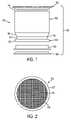
- This filtration testing system 60includes a funnel 10 that includes a fluid-holding cup 12 for receiving an amount of a fluid to be tested and a filter ring 20 having a filter 26 (e.g., a filtration mesh) disposed across its opening. More specifically, the cup 12 includes a top end 14 , a bottom end 16 having a width (e.g., diameter) less than that of the top end 14 , and a frusto-conical section 18 .
- the filter ring 20includes a wide portion 22 and a narrow portion 24 having a width (e.g., diameter) less than that of the wide portion 22 .
- the filter 26is disposed generally between the wide portion 22 and the narrow portion 24 .
- the filter ring 20is frangibly attached, at frangible connection 28 , to the bottom end 16 of the cup 12 .
- the frangible connection 28is constructed and arranged to break upon application to the funnel 10 of a sufficient compressive axial force, thereby permitting the narrow section 24 of the filter ring to collapse into the bottom end 16 of the cup 12 . After the frangible connection 28 is broken, the filter ring 20 and cup 12 can be separated from each other.
- the system 60further includes a growth medium plate 30 (e.g., an open-ended agar plate), a lower cover plate 40 , and an upper cover plate 50 .
- a growth medium plate 30e.g., an open-ended agar plate
- a lower cover plate 40e.g., a lower cover plate 40
- an upper cover plate 50e.g., an upper cover plate
- the filter ring 20can be connected to the growth medium plate 30 .
- the growth medium plate 30has a size and shape that conforms to the interior of the wide portion 22 of the filter ring 20 , permitting the plate 30 to be snugly inserted into the wide portion 22 as shown FIG. 3 .
- the growth medium plate 30includes a layer of growth medium 32 supported by a lattice structure 34 .
- An inner extension 36is preferably circular and projects away from the growth medium 32 and lattice structure 34 , generally encircling the growth medium 32 and the lattice structure 34 .
- the lower cover plate 40has a size and shape that conforms to the interior of the growth medium plate 30 , permitting the lower cover plate 40 to be snugly inserted into the growth medium plate 30 as shown FIG. 3 .
- a top surface 42 of the lower cover plate 40makes contact with the inner extension 36 , thereby forming a partial enclosure surrounding the growth medium 32 and the lattice structure 34 .
- the upper cover plate 50includes a first extension 52 and a second extension 54 .
- the first extension 52has a size and shape that permits that upper cover plate 50 to be secured to the top end 14 of cup 12 by inserting the first extension 52 into the cup 12 .
- the second extension 54has a size and shape that permits the upper cover plate 50 to be secured to the narrow portion 24 of the filter ring 20 by inserting the second extension 54 into the narrow portion 24 .
- the funnel 10in combination with the growth medium plate 30 , the upper cover plate 50 , and the lower cover plate 40 , make up the fluid contamination detection system 60 having an overall axial length L.
- a suitable system of the type shown in FIGS. 1-3is the MilliflexTM HAWG 0.45 ⁇ M, sterilized filtration funnel available from the Millipore Corporation, Bedford, Mass. (Cat. No. MXHAWG124). This system may further include, for example, a Prefilled MilliflexTM Cassette containing tryptic soy agar available from the Millipore Corporation (Cat. No. MXSMCTS48).
- the funnel 10is placed on a suction mechanism, or vacuum suction, (such as the MilliflexTM Sensor II automatic vacuum available from the Millipore Corporation (Cat. No. MXP520015)), a prescribed volume of fluid (e.g., about 10 mL) is then poured into the cup 12 , and the fluid contents of the cup 12 are drawn through the filter 26 of the filter ring 20 .
- a prescribed volume of fluide.g., about 10 mL
- the growth medium plate 30is joined to the filter ring 20 so that the growth medium 32 contained within the growth medium plate 30 contacts the filter 26 of the filter ring 20 . Thereafter, the filter ring 20 and growth medium plate 30 are separated from the cup 12 .
- the filter 10 and growth medium plate 30are manually squeezed between the palms and fingers of an operator's hands to apply an axial compressive force to the filter 10 and growth medium plate 30 that is sufficient to break the frangible connection 28 joining the cup 12 and ring 20 so that the narrow portion 24 of the filter ring 20 collapses into the bottom end 16 of the cup 12 .
- the filter ring 20 and growth medium plate 30are then separated from the cup 12 , and the upper cover plate 50 is joined to the open end of the filter ring 20 before incubating the enclosed growth medium plate 30 at a temperature of about 37° C.
- the growth medium plate 30is examined at prescribed time intervals, e.g., 24, 48, and 72 hours, and the number of colonies that have formed on the plate (the bioburden) is determined.
- a fluid contamination detection systemis especially important for the clinical diagnostics industry, where the presence of biological contaminants in fluids used to manufacture reagents for commercial test kits could affect the results of assays performed using those test kits.
- a problem with the fluid contamination detection system and procedure described aboveis that laboratory and manufacturing facilities might have to perform dozens of fluid contamination detection tests in a day. As a consequence, an operator may be required to repeatedly apply a manual force with their hands to separate filter ring 20 and growth medium plate 30 combinations from corresponding cups 12 , often resulting in discomfort to the operator's hands or, more seriously, causing repetitive stress injuries, such as carpal tunnel syndrome. Accordingly, there is a need for a device and method that overcome the problems associated with isolating filter ring 20 and growth medium plate 30 combinations in traditional detection systems.
- the present inventionprovides a novel solution to the repetitive stress problems associated with conventional methods of testing fluids for the presence of contaminants.
- a device for applying an axial compressive force to a fluid contamination detection systemcomprising a funnel in order to break a frangible connection joining first and second members of the funnel.
- the deviceincludes a stop element, a movable platform supported relative to a base, and an actuating mechanism.
- the platformis disposed in an opposed, spaced-apart relationship relative to the stop element.
- the platformis movable relative to the stop element between a first position in which the platform is spaced-apart from the stop element by a distance greater than the axial length of the detection system and a second position in which the platform is spaced-apart from the stop element by a distance less than the axial length of the detection system.
- the actuating mechanismcauses movement of the platform between the first and second positions.
- the platformis movable from the first position to the second position during which movement a portion of the detection system contacts the stop element, resulting in an axial compressive force that breaks the frangible connection joining the first and second members of the funnel.
- a filter snapper systemwhich includes a fluid contamination detection system comprising a funnel having first and second members joined to each other by a frangible connection in combination with the device for applying an axial compressive force to the fluid contamination detection system for breaking the frangible connection as described above.
- Another aspect of the inventionis embodied by a method for separating first and second members of a funnel joined to each other by a frangible connection using the device for applying an axial compressive force to the fluid contamination detection system for breaking the frangible connection as described above.
- the methodcomprises the steps of placing the funnel on the platform of the device while the platform is in the first position, activating the actuating mechanism, thereby causing the platform to move until a portion of the funnel engages the stop element, applying an axial compressive force to the funnel sufficient to break the frangible connection without damaging the funnel, and separating the first and second members of the funnel from each other.
- a predetermined amount of a fluidis provided to a funnel which includes a first member defining a fluid reservoir for receiving the fluid, a second member joined to the first member by a frangible connection, and a filter, which is adapted to trap biological contaminants present in the fluid, disposed on the second member. Fluid is passed from the first member of the funnel through the filter disposed on the second member, thereby trapping biological contaminants present in the fluid on the filter.
- a growth medium plateis joined to the second member of the funnel in such a manner that the filter is in contact with a growth medium contained within the growth medium plate.
- the funnelis positioned on the platform of the device for applying axial force when the platform is in the first position.
- the actuating mechanismis then activated, thereby causing the platform to move from the first position toward the second position until a portion of the funnel contacts the stop element.
- An axial compressive forceis applied to the funnel, and the force is sufficient to break the frangible connection without damaging the second member of the funnel.
- the first and second members of the funnelare separated from each other, and the growth medium plate is sealed by placing a cover plate on an open end of the second member of the funnel.
- the growth medium plateis incubated for a period of time and under conditions sufficient for biological contaminants trapped on the filter to grow; and the filter is examined after incubating to determine the presence or amount of biological contaminants on filter.
- Another aspect of the inventionis embodied by a method for detecting the presence of biological contaminants in a fluid.
- the methodcomprises the steps of providing a predetermined amount of a fluid to a funnel comprising a first member defining a fluid reservoir for receiving the fluid, a second member joined to the first member by a frangible connection, and a filter disposed on the second member and adapted to trap biological contaminants present in the fluid.
- the fluidis passed from the first member through the filter disposed on the second member, thereby trapping biological contaminants present in the fluid on the filter.
- the funnelis positioned on a mechanized device constructed and arranged to apply an axial compressive force to the funnel sufficient to break said frangible connection joining the first and second members, and mechanized device is activated, thereby causing the device to apply the axial compressive force to the funnel sufficient to break the frangible connection.
- mechanized deviceis activated, thereby causing the device to apply the axial compressive force to the funnel sufficient to break the frangible connection.
- the first and second members of the funnelare separated from each other.
- a growth medium plateis joined to the second member of the funnel in such a manner that the filter is in contact with a growth medium contained within the growth medium plate.
- the second member and the growth medium plate joined theretoare incubated for a period of time and under conditions sufficient for biological contaminants trapped on the filter to grow.
- the filteris then examined to determine the presence or amount of biological contaminants on the filter.
- FIG. 1is an exploded view, shown in side elevation, of components of a conventional filtration testing system.
- FIG. 2is a plan view of a filter ring of the filtration testing system of FIG. 1 .
- FIG. 3is an exploded view, shown in vertical cross-section, of components of the filtration testing system of FIG. 1 .
- FIG. 4is a perspective view of a filter snapper device according to an exemplary embodiment of the present invention.
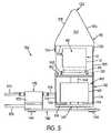
- FIG. 5is a front elevation view of the filter snapper device according to an exemplary embodiment of the present invention in which a movable platform thereof is in a first position with a filtration testing system, shown in phantom, disposed on the movable platform.
- FIG. 6is a front elevation view of the filter snapper device according to an exemplary embodiment of the present invention in which the movable platform is in a second position.
- FIGS. 4-6show a filter snapper device 100 according to an exemplary embodiment of the present invention.
- the filter snapper device 100comprises a housing 110 , a movable platform 150 mounted within the housing 110 , an actuating mechanism 160 for causing movement of the platform 150 , and a valve 170 for controlling the actuating mechanism 160 .
- the housing 110 and the valve 170are mounted to a base plate 140 .
- the housing 110has a lower portion 112 , a bottom plate 118 , a back plate 120 , and a hood 122 .
- the lower portion 112comprises side walls 114 , 116 .
- the hood 122comprises a front plate 124 , top plates 126 , 128 , side walls 130 , 132 , and a stop surface 134 .
- the distance between the side walls 130 , 132 of the hood 122is preferably at least as great as the distance between the side walls 114 , 116 of the lower portion 112 .
- the housing 110is shown with the side walls 130 , 132 of the hood 122 separated from the side walls 114 , 116 of the lower portion 112 .
- the gap between the hood 122 and the lower portion 112allows easy access for placement or removal of the testing system 60 (shown in phantom in FIGS. 5 and 6 ) onto or from the platform 150 .
- the side walls 130 , 132 of the hood 122could extend to and be continuous with the side walls 114 , 116 of the lower portion 112 .
- the housing 110 shownis rectangular with a triangular hood 122 as defined by top plates 126 , 128 .
- the housing 110could be, for example, cylindrical with a conical or hemispherical hood.
- the top plates 126 , 128are angled with respect to each other and are connected along upper edges thereof to form a triangular hood 122 so that the housing 110 can be placed under a vertical laminar flow hood while causing minimal disruption of the downwardly directed airflow.
- the transition from top plate 126 to top plate 128is preferably rounded, as are the transitions between top plates 126 , 128 and side walls 130 , 132 , respectively.
- air flowing downwardly over the housing 110will experience less disruption than if these transitions were sharply angled.
- the platform 150is attached to the actuating mechanism 160 , which in turn is attached to bottom plate 118 of housing 110 , and is movable relative to the housing 110 in a reciprocating manner in upward and downward directions.
- the platform 150is disposed in an opposed, spaced-apart relationship with respect to the stop surface 134 of the housing 110 .
- the actuating mechanism 160may comprise a pneumatic actuator, represented in FIGS. 5 and 6 by cylinder 162 and shaft (i.e., pneumatic piston shaft) 164 extending from cylinder 162 and attached to platform 150 .
- the preferred pneumatic actuator for use in the present inventionis a single acting, 11 ⁇ 2 inch bore, 3 ⁇ 8 inch stroke Flat-1® cylinder available from Bimba Manufacturing Company of Monee, Ill. (Model No. FOS-170.375-3R).
- the actuatorpreferably generates a compressive axial force of about 40 pounds-force.
- the valve 170is a 3-way valve, preferably a 3-way air switch available from Mead Fluid Dynamics Inc. of Chicago, Ill. as Model No. MV-5.
- the valve 170controls air flow from a pressure line 174 connected to a source of pressurized air (not shown), through the valve 170 , to line 176 extending to the pneumatic cylinder 162 coupled to the platform 150 .
- the source of pressurized aircould be a wall-mounted conduit connected to a compressor, or it could be a self-contained pressurized air cannister, which would give the device 100 some level of portability and allow it to be operable where a source of pressurized air is not otherwise available.
- Bleed line 178allows air flow from the pneumatic cylinder 162 .
- a trigger plate 172is pivotally connected to the valve 170 and can be operated by pressing it downwardly.
- the pneumatic cylinder 162In a neutral position, the pneumatic cylinder 162 is connected to bleed line 178 , and the shaft 164 is preferably spring biased into a first, downward position (see FIG. 5 ). Pressing the trigger plate 172 causes the pneumatic cylinder 162 to be connected to the pressure line 174 , thereby pressurizing the pneumatic cylinder 162 to cause the shaft 164 to extend relative to the cylinder 162 , against the spring bias, into a second, upward position (see FIG. 6 ).
- Releasing the trigger plate 172will again connect the pneumatic cylinder 162 with the bleed line 178 , thereby de-pressurizing the pneumatic cylinder 162 and permitting the shaft 164 and the movable platform 150 to return, under the force of the spring bias, to the first position.
- valve 162could be controlled by a valve placed on the floor and operated by a foot-operated trigger or plate.
- the valve of this embodimentis preferably a 3-way valve switch available from LINEMASTER Switch Corporation of Woodstock, Conn. (Cat. No. 3B-30A2-S).
- the valvecan be operated by a robot, a mechanical device, or the like.
- the valvepneumatically actuates the movable platform 150 via pneumatic cylinder 162 .
- the movable platform 150can be actuated by a hydraulic system, electric motor, solenoid, or the like.
- the pneumatic cylinder 162cooperates with the valve 170 , and moves the platform 150 with respect to the stop surface 134 between the first and second positions. In the first position, the distance between the platform 150 and the stop surface 134 is greater than the axial length L of the filtration testing system 60 . (See FIG. 3 ). This is illustrated in FIG. 5 in which the filtration testing system 60 is placed on the platform 150 with the shaft 164 of the actuating mechanism 160 in the downward position.
- the entire filtration testing system 60including funnel 10 , growth medium plate 30 , lower cover plate 40 , and upper cover plate 50 —be placed on the platform 150 , in order to simplify the drawings, growth medium plate 30 , lower cover plate 40 , and upper cover plate 50 are not explicitly shown in FIGS. 5 and 6 .
- the distance between the platform 150 and the stop surface 134is less than the axial length L of the funnel 10 and the growth medium plate 30 joined together prior to breaking the frangible connection 28 joining the filter ring 20 to the cup 12 .
- FIG. 6illustrates in which the shaft 164 of the actuating mechanism 160 is in the upward position, the funnel 10 and the growth medium plate 30 combination is in contact with both the platform 150 and the stop surface 134 , and the narrow portion 24 of the filter ring 20 is collapsed into the bottom 16 of the cup 12 .
- the housing 110 and the orientations of the platform 150 and the stop surface 134play no roll in the generation of the axial force. That is, the housing could comprise any structure that will support the stop surface 134 in an opposed, spaced relationship with respect to the platform 150 , and it is not necessary to the functioning of the device 100 that the housing include, e.g., the lower portion 112 and/or hood 122 .
- the relative positions of the stop surface 134 and the platform 150could be switched, with a moveable platform disposed above a stop surface.
- a dedicated stop surfacecould be omitted, and the platform could be supported a suitable distance above the base plate 140 , with the base plate 140 functioning as a stop surface.
- the filtration testing system 60would be placed on the stop surface and the platform would be actuated in a downward motion until it contacts and applies the required axial force to the funnel.
- the filtration testing system 60could be compressed between two spaced-apart surfaces that are each movable with respect to the other.
- stop surface and the moveable platformcould both be supported—e.g., by the base plate 140 —in a horizontally spaced-apart relation.
- Such an arrangementwould preferably include means for cradling the filtration funnel system 60 to keep it from rolling before being compressed.
- the funnel 10is joined to the growth medium plate 30 such that the growth medium 32 is in contact with the filter 26 .
- the upper cover plate 50 and the lower cover plate 40are placed on the funnel 10 and the growth medium plate 30 , respectively, and the funnel 10 , with the growth medium plate 30 joined thereto, is then placed on and supported by the platform 150 , which is in its first position, as shown in FIG. 5 Alternatively, the funnel 10 may be placed directly on the platform 150 prior to attaching the growth medium plate 30 to the filter ring 20 .
- the funnel 10is positioned on the platform 150 by a positioning fence 152 mounted to or formed on the platform 150 .
- positioning fence 152is a curved, upstanding wall having a curvature generally conforming to that of the filter ring 20 .
- the platform 150is actuated by the valve 170 (via trigger plate 172 ), which supplies air under pressure into the pneumatic cylinder 162 , thereby extending the shaft 164 and moving the platform 150 and the funnel 10 and growth medium plate 30 combination upward from the first position.
- the platform 150continues to move the funnel 10 and associated growth medium plate 30 upward until a portion of the filtration testing system 60 , e.g., the upper cover plate 50 , engages or abuts against the stop surface 134 .
- a portion of the filtration testing system 60e.g., the upper cover plate 50
- an axial compressive forceis applied to the testing system 60 .
- the axial compressive forceis sufficient to break the frangible connection 28 joining the filter ring 20 and the cup 12 , thereby collapsing the narrow portion 24 of the filter ring into the bottom end 16 of the cup 12 (see FIG. 6 ).
- the axial compressive forceis not, however, so great that the filter ring 20 or the growth medium plate 30 is damaged (e.g., cracked, warped, crushed, bent, etc.) in the process.
- valve 170When the valve 170 is released (via trigger plate 172 ), air is permitted to escape the pneumatic cylinder 162 through the bleed line 178 and, consequently, the shaft 164 retracts into the cylinder 162 and the platform 150 returns to the first position so that the cup 12 and filter ring 20 components of the funnel 10 can be removed from the platform 150 .
- the top cover plate 50is placed on the open, upper end of the filter ring 20 .
- the cup 12can be disposed of in any suitable disposal means.
- the growth medium plate 30 and associated filter ring 20are then exposed to conditions sufficient to promote the biological growth of biological contaminants (e.g., bacteria or fungi) that may be present on the filter 26 .
- biological contaminantse.g., bacteria or fungi
- the growth medium plate 30 and associated filter ring 20may be placed in an incubator at 37° C. for a set period of time or times and examined at the end of each period of time for changes, such as the appearance of colony forming units (“CFU”). If, based on this examination, there is an indication that the bioburden (i.e., the number of CFU) of the fluid sample is too high, then the source of the contaminated fluid can be disposed of before it is used in sterile laboratory or manufacturing procedures.
- CFUcolony forming units
- the filter snapper device 100is preferably washed at the completion of the procedure with a solution made up of 9 parts water and 1 part bleach, followed by a wash with 70% alcohol. Because of the corrosive nature of the bleach solution, the filter snapper device 100 is preferably made of electro polished 316 stainless steel. To facilitate cleaning, all housing joints are welded. To further facilitate cleaning, housing 110 is separated from base plate 140 by spacer elements 142 disposed between the base plate 140 and the bottom plate 118 of the housing 110 . Spacer elements 142 are preferably formed from Delrin® acetyl resin.
- the actuating mechanism 160is separated from the bottom of the housing 110 by means of spacers 166 —preferably formed from stainless steel—disposed between the bottom plate 118 and the actuating mechanism 160 .
- spacers 166preferably formed from stainless steel
- feet 144are disposed on the bottom of the base plate 140 to provide a separation between the base plate 140 and a surface upon which the filter snapper device 100 may be supported.
Landscapes
- Chemical & Material Sciences (AREA)
- Chemical Kinetics & Catalysis (AREA)
- Sampling And Sample Adjustment (AREA)
- Apparatus Associated With Microorganisms And Enzymes (AREA)
- Measuring Or Testing Involving Enzymes Or Micro-Organisms (AREA)
- Food-Manufacturing Devices (AREA)
- Piezo-Electric Or Mechanical Vibrators, Or Delay Or Filter Circuits (AREA)
- Filters For Electric Vacuum Cleaners (AREA)
Abstract
Description
Claims (18)
Priority Applications (2)
| Application Number | Priority Date | Filing Date | Title |
|---|---|---|---|
| US10/951,875US7435576B2 (en) | 2003-09-30 | 2004-09-29 | Filter snapper |
| US12/126,091US7592155B2 (en) | 2003-09-30 | 2008-05-23 | Filter snapper |
Applications Claiming Priority (2)
| Application Number | Priority Date | Filing Date | Title |
|---|---|---|---|
| US50673303P | 2003-09-30 | 2003-09-30 | |
| US10/951,875US7435576B2 (en) | 2003-09-30 | 2004-09-29 | Filter snapper |
Related Child Applications (1)
| Application Number | Title | Priority Date | Filing Date |
|---|---|---|---|
| US12/126,091DivisionUS7592155B2 (en) | 2003-09-30 | 2008-05-23 | Filter snapper |
Publications (2)
| Publication Number | Publication Date |
|---|---|
| US20050069973A1 US20050069973A1 (en) | 2005-03-31 |
| US7435576B2true US7435576B2 (en) | 2008-10-14 |
Family
ID=34421543
Family Applications (2)
| Application Number | Title | Priority Date | Filing Date |
|---|---|---|---|
| US10/951,875Active2026-07-24US7435576B2 (en) | 2003-09-30 | 2004-09-29 | Filter snapper |
| US12/126,091Expired - LifetimeUS7592155B2 (en) | 2003-09-30 | 2008-05-23 | Filter snapper |
Family Applications After (1)
| Application Number | Title | Priority Date | Filing Date |
|---|---|---|---|
| US12/126,091Expired - LifetimeUS7592155B2 (en) | 2003-09-30 | 2008-05-23 | Filter snapper |
Country Status (8)
| Country | Link |
|---|---|
| US (2) | US7435576B2 (en) |
| EP (1) | EP1675667B9 (en) |
| JP (1) | JP2007508013A (en) |
| AT (1) | ATE401115T1 (en) |
| AU (1) | AU2004277425B2 (en) |
| CA (1) | CA2534470C (en) |
| DE (1) | DE602004015131D1 (en) |
| WO (1) | WO2005032689A1 (en) |
Cited By (1)
| Publication number | Priority date | Publication date | Assignee | Title |
|---|---|---|---|---|
| US11731083B2 (en) | 2017-09-06 | 2023-08-22 | Merck Patent Gmbh | Filtration assembly and method for microbiological testing |
Families Citing this family (13)
| Publication number | Priority date | Publication date | Assignee | Title |
|---|---|---|---|---|
| FR2897941B1 (en)* | 2006-02-24 | 2009-01-16 | Millipore Corp | DEVICE AND METHOD FOR RAPID MICROBIOLOGICAL ANALYSIS. |
| FR2897783B1 (en)* | 2006-02-24 | 2008-05-30 | Millipore Corp | DEVICE FOR MICROBIOLOGICAL CONTROL, CONTROL AND INCUBATION ASSEMBLIES COMPRISING THE SAME, AND METHOD FOR CARRYING OUT THE SAME |
| FR2897873B1 (en)* | 2006-02-24 | 2008-05-30 | Millipore Corp | METHOD FOR RAPID MICROBIOLOGICAL ANALYSIS |
| FR2915487B1 (en)* | 2007-04-26 | 2009-06-05 | Millipore Corp | ASSEMBLY AND METHOD FOR MICROBIOLOGICAL ANALYSIS |
| JP5385304B2 (en)* | 2008-01-09 | 2014-01-08 | スクリーンセル | Apparatus and method for separating and culturing living cells on a filter or extracting genetic material of the cells |
| FR2955120B1 (en)* | 2010-01-14 | 2012-02-10 | Millipore Corp | METHOD AND TOOL FOR MEMBRANE TRANSFER |
| FR2956821B1 (en)* | 2010-02-26 | 2012-04-27 | Millipore Corp | DEVICE FOR SEPARATING A MEMBRANE FROM A SUPPORT |
| EP2780707B1 (en) | 2012-05-02 | 2016-02-24 | Charles River Laboratories, Inc. | Method of detecting viable cells in a cell sample |
| CN105874052B (en)* | 2013-11-04 | 2019-05-21 | 查尔斯河实验室公司 | Filtration system and its use |
| SG11202001840RA (en)* | 2017-09-06 | 2020-03-30 | Merck Patent Gmbh | Filtration assembly and method for microbiological testing |
| JP7407204B2 (en)* | 2019-04-09 | 2023-12-28 | ビオメリュー | Device for determining the presence of bacterial contaminants in fluids |
| JP7197867B2 (en)* | 2020-03-31 | 2022-12-28 | 国立研究開発法人日本原子力研究開発機構 | Vacuum filtration device |
| CN119643259B (en)* | 2024-11-29 | 2025-10-03 | 中山大学 | A vacuum filtration device for water quality testing |
Citations (18)
| Publication number | Priority date | Publication date | Assignee | Title |
|---|---|---|---|---|
| US4235164A (en) | 1979-06-08 | 1980-11-25 | Allen A Phil | Apparatus for crushing beverage cans |
| US4265170A (en) | 1979-08-21 | 1981-05-05 | Schulze Jr Everett E | Solenoid actuated container crusher |
| US4316410A (en)* | 1979-11-19 | 1982-02-23 | Davis Jr Charles M | Compact can crusher |
| US4463670A (en) | 1982-11-05 | 1984-08-07 | Thomas Robert C | Can crusher |
| US4599941A (en) | 1984-11-27 | 1986-07-15 | Boro Recycling, Inc. | Apparatus for crushing containers |
| US4614585A (en) | 1981-03-02 | 1986-09-30 | Sybron Corporation | Frangible bonded disposable filtration unit with recoverable filter |
| US4696227A (en)* | 1986-05-16 | 1987-09-29 | Buskirk W Jeffrey Van | Press for compacting small scale objects |
| US4821969A (en) | 1988-06-03 | 1989-04-18 | Richard W. Fox | Aluminum can crusher |
| EP0463897A1 (en) | 1990-06-28 | 1992-01-02 | Millipore S.A. | Filter membrane support and funnel for filtering liquids for microbiological analysis thereof |
| US5202262A (en) | 1984-01-31 | 1993-04-13 | Millipore Corporation | Apparatus for microbiological testing of liquids |
| US5297479A (en)* | 1992-11-03 | 1994-03-29 | Lisle Corporation | Oil filter crusher apparatus |
| US5308483A (en) | 1992-08-27 | 1994-05-03 | Gelman Sciences Inc. | Microporous filtration funnel assembly |
| US5383397A (en)* | 1993-05-06 | 1995-01-24 | Kcs Industries Inc. | Oil filter crushing apparatus |
| US5905038A (en) | 1995-05-25 | 1999-05-18 | Severn Trent Water Limited | Filtration and culture methods and apparatus |
| WO2001048142A1 (en) | 1999-12-24 | 2001-07-05 | Millipore | Device for microbiological examination of a sample of liquid and method for draining this device |
| WO2001059157A2 (en) | 2000-02-08 | 2001-08-16 | Millipore Corporation | Process for the enumeration and identification of microorganisms |
| US6358730B1 (en) | 1997-01-29 | 2002-03-19 | Pall Corporation | Filtration assembly and culture device |
| US20020083851A1 (en)* | 2001-01-02 | 2002-07-04 | Gragg Ronnie G. | Apparatus for crushing cans |
Family Cites Families (3)
| Publication number | Priority date | Publication date | Assignee | Title |
|---|---|---|---|---|
| GB9510634D0 (en)* | 1995-05-25 | 1995-07-19 | Sev Trent Water Ltd | Filtration and culture methods and apparatus |
| JPH09215491A (en)* | 1996-02-09 | 1997-08-19 | Nippon Keieishiya Kyokai Keiei Kenkyu Shidou Center:Kk | Fungus dispenser |
| CA2437389A1 (en)* | 2001-02-06 | 2002-08-15 | Pall Corporation | Filtration assembly |
- 2004
- 2004-09-29USUS10/951,875patent/US7435576B2/enactiveActive
- 2004-09-30DEDE602004015131Tpatent/DE602004015131D1/ennot_activeExpired - Lifetime
- 2004-09-30AUAU2004277425Apatent/AU2004277425B2/ennot_activeCeased
- 2004-09-30JPJP2006534134Apatent/JP2007508013A/enactivePending
- 2004-09-30ATAT04789432Tpatent/ATE401115T1/ennot_activeIP Right Cessation
- 2004-09-30EPEP04789432Apatent/EP1675667B9/ennot_activeExpired - Lifetime
- 2004-09-30CACA2534470Apatent/CA2534470C/ennot_activeExpired - Fee Related
- 2004-09-30WOPCT/US2004/032326patent/WO2005032689A1/enactiveApplication Filing
- 2008
- 2008-05-23USUS12/126,091patent/US7592155B2/ennot_activeExpired - Lifetime
Patent Citations (18)
| Publication number | Priority date | Publication date | Assignee | Title |
|---|---|---|---|---|
| US4235164A (en) | 1979-06-08 | 1980-11-25 | Allen A Phil | Apparatus for crushing beverage cans |
| US4265170A (en) | 1979-08-21 | 1981-05-05 | Schulze Jr Everett E | Solenoid actuated container crusher |
| US4316410A (en)* | 1979-11-19 | 1982-02-23 | Davis Jr Charles M | Compact can crusher |
| US4614585A (en) | 1981-03-02 | 1986-09-30 | Sybron Corporation | Frangible bonded disposable filtration unit with recoverable filter |
| US4463670A (en) | 1982-11-05 | 1984-08-07 | Thomas Robert C | Can crusher |
| US5202262A (en) | 1984-01-31 | 1993-04-13 | Millipore Corporation | Apparatus for microbiological testing of liquids |
| US4599941A (en) | 1984-11-27 | 1986-07-15 | Boro Recycling, Inc. | Apparatus for crushing containers |
| US4696227A (en)* | 1986-05-16 | 1987-09-29 | Buskirk W Jeffrey Van | Press for compacting small scale objects |
| US4821969A (en) | 1988-06-03 | 1989-04-18 | Richard W. Fox | Aluminum can crusher |
| EP0463897A1 (en) | 1990-06-28 | 1992-01-02 | Millipore S.A. | Filter membrane support and funnel for filtering liquids for microbiological analysis thereof |
| US5308483A (en) | 1992-08-27 | 1994-05-03 | Gelman Sciences Inc. | Microporous filtration funnel assembly |
| US5297479A (en)* | 1992-11-03 | 1994-03-29 | Lisle Corporation | Oil filter crusher apparatus |
| US5383397A (en)* | 1993-05-06 | 1995-01-24 | Kcs Industries Inc. | Oil filter crushing apparatus |
| US5905038A (en) | 1995-05-25 | 1999-05-18 | Severn Trent Water Limited | Filtration and culture methods and apparatus |
| US6358730B1 (en) | 1997-01-29 | 2002-03-19 | Pall Corporation | Filtration assembly and culture device |
| WO2001048142A1 (en) | 1999-12-24 | 2001-07-05 | Millipore | Device for microbiological examination of a sample of liquid and method for draining this device |
| WO2001059157A2 (en) | 2000-02-08 | 2001-08-16 | Millipore Corporation | Process for the enumeration and identification of microorganisms |
| US20020083851A1 (en)* | 2001-01-02 | 2002-07-04 | Gragg Ronnie G. | Apparatus for crushing cans |
Non-Patent Citations (4)
| Title |
|---|
| EPO Office Action, European Patent Application No. 04 789 432.4, Oct. 9, 2006. |
| Milliflex(R) 100 Filtration Funnel, Certificate of Quality, Dec. 2003, Millipore Corporation, Bedford, MA 01730. |
| PCT Search Report, International Application No. PCT/US04/032326, Feb. 4, 2005. |
| PCT Written Opinion, International Application No. PCT/US04/032326, Feb. 4, 2005. |
Cited By (1)
| Publication number | Priority date | Publication date | Assignee | Title |
|---|---|---|---|---|
| US11731083B2 (en) | 2017-09-06 | 2023-08-22 | Merck Patent Gmbh | Filtration assembly and method for microbiological testing |
Also Published As
| Publication number | Publication date |
|---|---|
| EP1675667B1 (en) | 2008-07-16 |
| CA2534470C (en) | 2011-01-25 |
| US20050069973A1 (en) | 2005-03-31 |
| US7592155B2 (en) | 2009-09-22 |
| AU2004277425A1 (en) | 2005-04-14 |
| EP1675667A1 (en) | 2006-07-05 |
| US20080220467A1 (en) | 2008-09-11 |
| JP2007508013A (en) | 2007-04-05 |
| EP1675667B9 (en) | 2009-03-04 |
| ATE401115T1 (en) | 2008-08-15 |
| CA2534470A1 (en) | 2005-04-14 |
| WO2005032689A1 (en) | 2005-04-14 |
| DE602004015131D1 (en) | 2008-08-28 |
| AU2004277425B2 (en) | 2009-12-03 |
Similar Documents
| Publication | Publication Date | Title |
|---|---|---|
| US7592155B2 (en) | Filter snapper | |
| JP2641986B2 (en) | A new and improved liquid sample aspiration and dispensing probe | |
| KR100473123B1 (en) | Filtration and extraction device and method of using the same | |
| EP0377264B1 (en) | Leakage detection system | |
| JP5301610B2 (en) | Apparatus and method for handling fluid for analysis | |
| JPH054020B2 (en) | ||
| JPH04503568A (en) | Liquid sample analysis device and liquid sample analysis method using a new and improved liquid sample aspiration and dispensing probe | |
| JPH07509061A (en) | Automated sampling or feeding/seeding equipment for bioreactors and similar devices | |
| DK2288921T3 (en) | The detection device. | |
| JP2795945B2 (en) | Microtiter plate washer | |
| JP2022543979A (en) | New reagent kit | |
| US20160203965A1 (en) | Surface Extraction Interface | |
| JP2003066055A (en) | Diagnostic support pipette assembly for automated aspiration and using method thereof | |
| JP4965572B2 (en) | Liquid dispensing device with cap and diaphragm | |
| CN217890747U (en) | Fixing device and filter core integrality test system | |
| JPH04296655A (en) | Liquid measuring method, automatic dispensing method using the same, and its device | |
| JP4238216B2 (en) | Filter device incorporating sampling volume control | |
| CN206177976U (en) | Pinch valve and automatic analyzer with pinch valve | |
| JP7423957B2 (en) | Cleaning equipment and cleaning method | |
| KR960014002B1 (en) | Leak detection system | |
| JPH0127097Y2 (en) | ||
| JPH0688226B2 (en) | Bead transfer device | |
| JPS6367070B2 (en) | ||
| RU160843U1 (en) | ULTRASONIC TRANSMITTER | |
| CN115646292A (en) | Reagent shakes even device for biological detection |
Legal Events
| Date | Code | Title | Description |
|---|---|---|---|
| FEPP | Fee payment procedure | Free format text:PAYOR NUMBER ASSIGNED (ORIGINAL EVENT CODE: ASPN); ENTITY STATUS OF PATENT OWNER: LARGE ENTITY | |
| AS | Assignment | Owner name:GEN-PROBE INCORPORATED, CALIFORNIA Free format text:ASSIGNMENT OF ASSIGNORS INTEREST;ASSIGNORS:BASHAR, REZA;CAMPER, DALE A.;REEL/FRAME:021481/0911 Effective date:20031223 | |
| STCF | Information on status: patent grant | Free format text:PATENTED CASE | |
| FPAY | Fee payment | Year of fee payment:4 | |
| AS | Assignment | Owner name:GOLDMAN SACHS BANK USA, NEW YORK Free format text:SECURITY AGREEMENT;ASSIGNORS:HOLOGIC, INC.;BIOLUCENT, LLC;CYTYC CORPORATION;AND OTHERS;REEL/FRAME:028810/0745 Effective date:20120801 | |
| AS | Assignment | Owner name:CYTYC SURGICAL PRODUCTS, LIMITED PARTNERSHIP, MASSACHUSETTS Free format text:SECURITY INTEREST RELEASE REEL/FRAME 028810/0745;ASSIGNOR:GOLDMAN SACHS BANK USA, AS COLLATERAL AGENT;REEL/FRAME:035820/0239 Effective date:20150529 Owner name:BIOLUCENT, LLC, MASSACHUSETTS Free format text:SECURITY INTEREST RELEASE REEL/FRAME 028810/0745;ASSIGNOR:GOLDMAN SACHS BANK USA, AS COLLATERAL AGENT;REEL/FRAME:035820/0239 Effective date:20150529 Owner name:CYTYC SURGICAL PRODUCTS, LIMITED PARTNERSHIP, MASS Free format text:SECURITY INTEREST RELEASE REEL/FRAME 028810/0745;ASSIGNOR:GOLDMAN SACHS BANK USA, AS COLLATERAL AGENT;REEL/FRAME:035820/0239 Effective date:20150529 Owner name:THIRD WAVE TECHNOLOGIES, INC., MASSACHUSETTS Free format text:SECURITY INTEREST RELEASE REEL/FRAME 028810/0745;ASSIGNOR:GOLDMAN SACHS BANK USA, AS COLLATERAL AGENT;REEL/FRAME:035820/0239 Effective date:20150529 Owner name:SUROS SURGICAL SYSTEMS, INC., MASSACHUSETTS Free format text:SECURITY INTEREST RELEASE REEL/FRAME 028810/0745;ASSIGNOR:GOLDMAN SACHS BANK USA, AS COLLATERAL AGENT;REEL/FRAME:035820/0239 Effective date:20150529 Owner name:GEN-PROBE INCORPORATED, MASSACHUSETTS Free format text:SECURITY INTEREST RELEASE REEL/FRAME 028810/0745;ASSIGNOR:GOLDMAN SACHS BANK USA, AS COLLATERAL AGENT;REEL/FRAME:035820/0239 Effective date:20150529 Owner name:CYTYC CORPORATION, MASSACHUSETTS Free format text:SECURITY INTEREST RELEASE REEL/FRAME 028810/0745;ASSIGNOR:GOLDMAN SACHS BANK USA, AS COLLATERAL AGENT;REEL/FRAME:035820/0239 Effective date:20150529 Owner name:HOLOGIC, INC., MASSACHUSETTS Free format text:SECURITY INTEREST RELEASE REEL/FRAME 028810/0745;ASSIGNOR:GOLDMAN SACHS BANK USA, AS COLLATERAL AGENT;REEL/FRAME:035820/0239 Effective date:20150529 | |
| AS | Assignment | Owner name:BANK OF AMERICA, N.A., AS COLLATERAL AGENT, NORTH CAROLINA Free format text:SECURITY AGREEMENT;ASSIGNORS:HOLOGIC, INC.;BIOLUCENT, LLC;CYTYC CORPORATION;AND OTHERS;REEL/FRAME:036307/0199 Effective date:20150529 Owner name:BANK OF AMERICA, N.A., AS COLLATERAL AGENT, NORTH Free format text:SECURITY AGREEMENT;ASSIGNORS:HOLOGIC, INC.;BIOLUCENT, LLC;CYTYC CORPORATION;AND OTHERS;REEL/FRAME:036307/0199 Effective date:20150529 | |
| FPAY | Fee payment | Year of fee payment:8 | |
| AS | Assignment | Owner name:CYTYC SURGICAL PRODUCTS, LIMITED PARTNERSHIP, MASSACHUSETTS Free format text:CORRECTIVE ASSIGNMENT TO CORRECT THE INCORRECT PATENT NO. 8081301 PREVIOUSLY RECORDED AT REEL: 035820 FRAME: 0239. ASSIGNOR(S) HEREBY CONFIRMS THE SECURITY INTEREST RELEASE;ASSIGNOR:GOLDMAN SACHS BANK USA, AS COLLATERAL AGENT;REEL/FRAME:044727/0529 Effective date:20150529 Owner name:GOLDMAN SACHS BANK USA, NEW YORK Free format text:CORRECTIVE ASSIGNMENT TO CORRECT THE INCORRECT PATENT NO. 8081301 PREVIOUSLY RECORDED AT REEL: 028810 FRAME: 0745. ASSIGNOR(S) HEREBY CONFIRMS THE SECURITY AGREEMENT;ASSIGNORS:HOLOGIC, INC.;BIOLUCENT, LLC;CYTYC CORPORATION;AND OTHERS;REEL/FRAME:044432/0565 Effective date:20120801 Owner name:BIOLUCENT, LLC, MASSACHUSETTS Free format text:CORRECTIVE ASSIGNMENT TO CORRECT THE INCORRECT PATENT NO. 8081301 PREVIOUSLY RECORDED AT REEL: 035820 FRAME: 0239. ASSIGNOR(S) HEREBY CONFIRMS THE SECURITY INTEREST RELEASE;ASSIGNOR:GOLDMAN SACHS BANK USA, AS COLLATERAL AGENT;REEL/FRAME:044727/0529 Effective date:20150529 Owner name:HOLOGIC, INC., MASSACHUSETTS Free format text:CORRECTIVE ASSIGNMENT TO CORRECT THE INCORRECT PATENT NO. 8081301 PREVIOUSLY RECORDED AT REEL: 035820 FRAME: 0239. ASSIGNOR(S) HEREBY CONFIRMS THE SECURITY INTEREST RELEASE;ASSIGNOR:GOLDMAN SACHS BANK USA, AS COLLATERAL AGENT;REEL/FRAME:044727/0529 Effective date:20150529 Owner name:SUROS SURGICAL SYSTEMS, INC., MASSACHUSETTS Free format text:CORRECTIVE ASSIGNMENT TO CORRECT THE INCORRECT PATENT NO. 8081301 PREVIOUSLY RECORDED AT REEL: 035820 FRAME: 0239. ASSIGNOR(S) HEREBY CONFIRMS THE SECURITY INTEREST RELEASE;ASSIGNOR:GOLDMAN SACHS BANK USA, AS COLLATERAL AGENT;REEL/FRAME:044727/0529 Effective date:20150529 Owner name:GEN-PROBE INCORPORATED, MASSACHUSETTS Free format text:CORRECTIVE ASSIGNMENT TO CORRECT THE INCORRECT PATENT NO. 8081301 PREVIOUSLY RECORDED AT REEL: 035820 FRAME: 0239. ASSIGNOR(S) HEREBY CONFIRMS THE SECURITY INTEREST RELEASE;ASSIGNOR:GOLDMAN SACHS BANK USA, AS COLLATERAL AGENT;REEL/FRAME:044727/0529 Effective date:20150529 Owner name:THIRD WAVE TECHNOLOGIES, INC., MASSACHUSETTS Free format text:CORRECTIVE ASSIGNMENT TO CORRECT THE INCORRECT PATENT NO. 8081301 PREVIOUSLY RECORDED AT REEL: 035820 FRAME: 0239. ASSIGNOR(S) HEREBY CONFIRMS THE SECURITY INTEREST RELEASE;ASSIGNOR:GOLDMAN SACHS BANK USA, AS COLLATERAL AGENT;REEL/FRAME:044727/0529 Effective date:20150529 Owner name:CYTYC CORPORATION, MASSACHUSETTS Free format text:CORRECTIVE ASSIGNMENT TO CORRECT THE INCORRECT PATENT NO. 8081301 PREVIOUSLY RECORDED AT REEL: 035820 FRAME: 0239. ASSIGNOR(S) HEREBY CONFIRMS THE SECURITY INTEREST RELEASE;ASSIGNOR:GOLDMAN SACHS BANK USA, AS COLLATERAL AGENT;REEL/FRAME:044727/0529 Effective date:20150529 Owner name:CYTYC SURGICAL PRODUCTS, LIMITED PARTNERSHIP, MASS Free format text:CORRECTIVE ASSIGNMENT TO CORRECT THE INCORRECT PATENT NO. 8081301 PREVIOUSLY RECORDED AT REEL: 035820 FRAME: 0239. ASSIGNOR(S) HEREBY CONFIRMS THE SECURITY INTEREST RELEASE;ASSIGNOR:GOLDMAN SACHS BANK USA, AS COLLATERAL AGENT;REEL/FRAME:044727/0529 Effective date:20150529 | |
| MAFP | Maintenance fee payment | Free format text:PAYMENT OF MAINTENANCE FEE, 12TH YEAR, LARGE ENTITY (ORIGINAL EVENT CODE: M1553); ENTITY STATUS OF PATENT OWNER: LARGE ENTITY Year of fee payment:12 |