US7435289B2 - Integrated air cleaner and vapor containment system - Google Patents
Integrated air cleaner and vapor containment systemDownload PDFInfo
- Publication number
- US7435289B2 US7435289B2US11/236,253US23625305AUS7435289B2US 7435289 B2US7435289 B2US 7435289B2US 23625305 AUS23625305 AUS 23625305AUS 7435289 B2US7435289 B2US 7435289B2
- Authority
- US
- United States
- Prior art keywords
- canister
- air
- air cleaner
- aperture
- fuel
- Prior art date
- Legal status (The legal status is an assumption and is not a legal conclusion. Google has not performed a legal analysis and makes no representation as to the accuracy of the status listed.)
- Expired - Fee Related, expires
Links
Images


Classifications
- F—MECHANICAL ENGINEERING; LIGHTING; HEATING; WEAPONS; BLASTING
- F02—COMBUSTION ENGINES; HOT-GAS OR COMBUSTION-PRODUCT ENGINE PLANTS
- F02M—SUPPLYING COMBUSTION ENGINES IN GENERAL WITH COMBUSTIBLE MIXTURES OR CONSTITUENTS THEREOF
- F02M35/00—Combustion-air cleaners, air intakes, intake silencers, or induction systems specially adapted for, or arranged on, internal-combustion engines
- F02M35/02—Air cleaners
- F02M35/024—Air cleaners using filters, e.g. moistened
- F—MECHANICAL ENGINEERING; LIGHTING; HEATING; WEAPONS; BLASTING
- F02—COMBUSTION ENGINES; HOT-GAS OR COMBUSTION-PRODUCT ENGINE PLANTS
- F02M—SUPPLYING COMBUSTION ENGINES IN GENERAL WITH COMBUSTIBLE MIXTURES OR CONSTITUENTS THEREOF
- F02M25/00—Engine-pertinent apparatus for adding non-fuel substances or small quantities of secondary fuel to combustion-air, main fuel or fuel-air mixture
- F02M25/08—Engine-pertinent apparatus for adding non-fuel substances or small quantities of secondary fuel to combustion-air, main fuel or fuel-air mixture adding fuel vapours drawn from engine fuel reservoir
- F02M25/0854—Details of the absorption canister
Definitions
- the present inventionrelates to a vapor containment system for an engine, and particularly to an engine vapor containment system that is at least partially formed as part of an air cleaner.
- Internal combustion enginesare often used to power outdoor power equipment such as lawnmowers, tillers, snow throwers, and the like.
- these enginesinclude a fuel system that supplies fuel for combustion.
- the fuel systemincludes a tank, in which fuel is stored for use.
- the volatility of the fuelallows a portion of the fuel to evaporate and mix with air within the tank.
- Changes in temperature, such as those between evening and daytime, as well as sloshing during usecan cause an increase or a decrease in the amount of fuel vapor in the tank as well as an increase or a decrease in the pressure within the tank.
- the pressure within the fuel tanktypically drops as fuel is drawn from the tank during engine operation.
- ventssuch as a vented fuel cap.
- the ventallows the excess air and fuel vapor to escape from the tank when the pressure increases, and also allows air to enter the tank when the pressure drops.
- the escape of fuel vaporreduces the fuel efficiency of the engine.
- the inventionprovides an air cleaner for an engine that includes a fuel tank and an air-fuel mixing device.
- the air cleanerincludes a housing that defines an internal filter space and a canister at least partially formed as part of the housing.
- the canisteris substantially non-permeable to fuel vapor.
- a first apertureprovides fluid communication between the fuel tank and the canister and a second aperture provides fluid communication between the canister and the air-fuel mixing device.
- the inventionalso provides an air cleaner for an engine that includes a fuel tank and an air-fuel mixing device.
- the air cleanerincludes a housing adapted to attach to the engine and a filter element supported by the housing and positioned to define a clean air space.
- a canisteris positioned substantially within the housing and includes an aperture that provides fluid communication between the clean air space and the canister.
- a first passageway apertureprovides fluid communication between the canister and the air-fuel mixing device and a second passageway aperture provides fluid communication between the canister and the fuel tank.
- the inventionalso provides an engine that includes a combustion chamber that is operable to combust an air-fuel mixture and an air-fuel mixing device operable to deliver the air-fuel mixture to the combustion chamber.
- the enginealso includes a fuel tank, an air cleaner including a housing that defines a clean air space, and a canister at least partially formed as part of the housing and including an aperture that provides fluid communication between the canister and the clean air space.
- a first passagewayprovides fluid communication between the canister and the air-fuel mixing device and a second passageway provides fluid communication between the canister and the fuel tank.
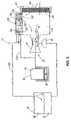
- FIG. 1is a perspective view of an engine including an air cleaner having a vapor containment system
- FIG. 2is a perspective view a the fuel tank, a carburetor, and the air cleaner of FIG. 1 ;
- FIG. 3is an exploded perspective view of the air cleaner of FIG. 1 ;
- FIG. 4is an enlarged perspective view of a portion of the air cleaner of FIG. 1 ;
- FIG. 5is a section view of the air cleaner of FIG. 1 , taken along line 5 - 5 of FIG. 2 ;
- FIG. 6is a schematic illustration of the vapor containment system during a pressure rise within the fuel tank when the engine is idle;
- FIG. 7is a schematic illustration of the vapor containment system during a pressure rise within the fuel tank when the engine is running;
- FIG. 8is a schematic illustration of the vapor containment system during a pressure drop within the fuel tank
- FIG. 9is a schematic illustration of the vapor containment system during a pressure drop within the fuel tank when the engine is running;
- FIG. 10is a perspective view of another air cleaner assembly embodying the invention.
- FIG. 11is an exploded perspective view of the air cleaner assembly of FIG. 10 ;
- FIG. 12is an enlarged exploded perspective view of a portion of the air cleaner assembly of FIG. 10 .
- an engine 10 including a fuel tank 15 , an air cleaner assembly 20 , and an air-fuel mixing device 25 that may include a carburetor 30 (shown in FIG. 2 )is illustrated.
- Engines 10 of this typeare often used to power outdoor power equipment such as lawnmowers, garden tractors, snow throwers, tillers, pressure washers, generators, and the like. While the illustrated engine 10 is a small engine (e.g., two or fewer cylinders), it should be understood that the invention will function with other types of engines including large internal combustion engines.
- the air cleaner assembly 20is positioned near an outer surface of the engine 10 such that air can be drawn from the atmosphere into the air cleaner assembly 20 .
- the air cleaner assembly 20filters particulate matter (e.g., dirt, pollen, debris, and the like) from the air and delivers the clean air to an air-fuel mixing device such as a carburetor 30 .
- the carburetor 30could be a float carburetor, a diaphragm carburetor or any other type of carburetor.
- the carburetor 30shown in FIG. 2 , includes a throttle plate 35 (shown schematically in FIGS. 6-9 ) that controls the quantity of air that passes through the carburetor 30 .
- the carburetor 30also includes a throat 40 that defines a venturi. As the air passes through the throat 40 , the venturi draws fuel from a fuel bowl 45 into the air stream and mixes the fuel and air to produce a combustible air-fuel mixture.
- the carburetor 30delivers the air-fuel mixture to a combustion chamber 50 where the mixture is combusted to produce usable power.
- the entire air-fuel flow path between and including the carburetor 30 and the inlet to the combustion chamber 50is considered to be part of the air-fuel mixing device 25 .
- the air-fuel mixing devicecould include a throttle body, one or more fuel injectors, and/or an intake manifold.
- the engine 10includes one or more pistons 55 (shown schematically in FIGS. 6-9 ) that reciprocate within one or more cylinders 60 to define one or more combustion chambers 50 .
- the illustrated engine 10includes a single piston 55 that reciprocates within a single cylinder 60 to define a single combustion chamber 50 .
- Other types of enginese.g., rotary engines, diesel engines, etc.
- the fuel tank 15is formed to fit around the outer portion of the engine 10 and to define an internal space 65 suitable for storing liquid fuel 70 .
- the tank 15includes a fill spout 75 formed in the top of the tank 15 and a cap 80 that threadably engages the fill spout 75 to substantially seal the tank 15 .
- a fuel line 85extends from a bottom portion of the tank 15 to the fuel bowl 45 of the carburetor 30 . The position of the fuel bowl 45 , below the fuel tank 15 , allows gravity alone to deliver a flow of fuel from the fuel tank 15 to the fuel bowl 45 .
- Other engines 10may include a fuel pump or other device that aids in moving the fuel from the tank 15 to the carburetor 30 or other air-fuel mixing device 25 .
- the air cleaner assembly 20is shown in an exploded view to better illustrate the various components.
- the air cleaner assembly 20includes a back plate 90 , a cover 95 , and a filter element 100 disposed between the back plate 90 and the cover 95 .
- a pleated paper filter element 100is employed, with other types of filter elements also being suitable for use.
- the filter element 100includes a perimeter portion 105 made from a resilient material such as urethane foam. The perimeter portion 105 abuts against one of, or both of the back plate 90 and the cover 95 to form a substantially air tight seal.
- the filter element 100separates the atmosphere from a clean air space 110 disposed substantially between the filter element 100 and the back plate 90 .
- the cover 95includes an outer surface 115 that is generally exposed when the engine 10 is assembled.
- the cover 95engages the back plate 90 to define a filter space 120 and to substantially enclose and protect the filter element 100 .
- One or more apertures 125are formed in the cover 95 to allow for the passage of air from the atmosphere into the air cleaner assembly 20 .
- the apertures 125are arranged to direct the incoming air to a dirty side 130 of the filter element.
- the cover 95also includes several tabs 135 that extend downward from the cover 95 .
- the tabs 135engage slots (not shown) that are formed in the back plate 90 to couple the cover 95 to the back plate 90 .
- a clamp space 145 formed at the top of the cover 95 , opposite the tabs 135engages a clamp 150 positioned on the back plate 90 to hold the cover 95 in the closed or assembled position.
- the clamp 150is releasable to allow for the removal, cleaning, and replacement of the filter element 100 as needed.
- fastenerssuch as screws, could be employed to attach the cover 95 to the back plate 90 .
- the inventionshould not be limited to the arrangement illustrated and described herein.
- the back plate 90attaches to the engine 10 and supports the remaining components of the filter assembly 20 .
- the back plate 90cooperates with the filter element 100 to substantially enclose the clean air space 110 .
- a large aperture 155is formed in the back plate 90 and is surrounded by a mounting flange 160 .
- the carburetor 30attaches directly to the mounting flange 160 such that clean air can pass from the clean air space 110 , through the aperture 155 , and directly into the carburetor 30 .
- Other constructionsmay employ a tube or other flow element disposed between the back plate 90 and the carburetor 30 to direct the air to the carburetor 30 .
- the back plate 90also includes a primer housing 165 at least partially formed as part of the back plate 90 , and a breather inlet 170 that extends from the back plate 90 .
- the breather inlet 170receives a flow of fluid from a crankcase and/or rocker box breather. Generally, this fluid contains some lubricant that is preferably returned to the crankcase when possible.
- the breather inlet 170 illustrated in FIG. 3directs the flow of fluid into the clean air space 110 of the filter assembly 20 . From the clean air space, the fluid can be combusted by the engine 10 , rather than being discharged to the atmosphere.
- the primer housing 165supports the components of a primer 175 and at least partially defines a fluid flow path between the primer 175 and the carburetor 30 .
- the primer 175is used to draw fuel from the fuel tank 15 to the carburetor 30 to aid in starting the engine 10 .
- a canister 180is at least partially formed as part of the back plate 90 of the filter assembly 20 .
- the canister 180includes walls that are substantially non-permeable to fluids such as air, water, fuel, oil, hydrocarbons, and the like.
- the canister 180defines an interior space 185 that is substantially separate from the filter space 120 .
- the canister 180includes two apertures 190 , 195 positioned near a lower end 200 of the canister 180 .
- Flow connectors 205 , 210extend around the apertures 190 , 195 and away from the canister 180 to provide connection points for flow devices such as pipes or tubes.
- the first aperture 190provides fluid communication between the fuel tank 15 and the interior space 185 of the canister 180 .
- the first aperture 190provides fluid communication between a top portion 215 of the fuel tank 15 and the interior space 185 of the canister 180 .
- a first flow path 220extends between the top portion 215 of the fuel tank 15 and the first aperture 190 .
- the second aperture 195provides fluid communication between the air-fuel mixing device 25 and the interior space 185 of the canister 180 .
- a second flow path 225is at least partially defined by a tube that extends from the second flow connector 210 to the air-fuel mixing device 25 in the flow path between the carburetor 30 and the combustion chamber 50 .
- the tubeextends directly into the carburetor 30 or the combustion chamber 50 , rather than into the flow path between the carburetor 30 and the combustion chamber 50 .
- the interior space 185 of the canister 180contains and supports a lower filter element 230 , an upper filter element 235 , a filter media 240 , a piston 245 , a spring 250 , and a cover 255 .
- the filter media 240adsorbs hydrocarbons, such as fuel vapor, that may be entrained in the fluid that passes through the canister 180 .
- One suitable filter media 240is activated charcoal, with other types of filter media 240 also being suitable for use.
- the lower filter element 230is positioned within the canister 180 and provides support for the filter media 240 .
- the lower filter element 230is rigid enough to support the filter media 240 and permeable enough to allow for the passage of fluid without allowing the passage of the filter media 240 .
- a metallic screenis employed. The screen includes openings that are large enough to allow for the passage of fluid but small enough to inhibit passage of the filter media 240 .
- the upper filter element 235is substantially the same as the lower filter element 230 . Thus, the upper filter element 235 and the lower filter element 230 sandwich and support the filter media 240 .
- the piston 245rests on top of the upper filter element 235 and is movable within the interior space 185 of the canister 180 .
- Several openings 260are formed in the piston 245 to allow for the relatively free flow of fluid past the piston 245 .
- the cover 255engages the top portion of the canister 180 to substantially enclose the interior space 185 .
- the cover 255is welded to the canister 180 , thus making the closure permanent.
- other closure meanssuch as threads are employed. Constructions that employ threads allow for the removal and replacement of the components disposed within the canister 180 .
- the spring 250is positioned between the piston 245 and the cover 255 to bias the piston 245 in a downward direction to compress the filter media 240 between the upper filter element 235 and the lower filter element 230 .
- the spring 250 and piston 245may be replaced with other means of supplying compressive force.
- other constructionsemploy urethane or polyester foams in place of the spring 250 and piston 245 .
- FIG. 4illustrates the bottom of the interior space 185 of the canister 180 .
- the first aperture 190extends into the center of the canister 180
- the second aperture 195terminates at an interior wall 265 of the canister 180 .
- a number of standoffs 270extend from the bottom of the canister 180 and provide support for the lower filter element 230 .
- a substantially empty spaceis defined beneath the filter media 240 and between the first aperture 190 and the second aperture 195 .
- FIG. 4Another opening 275 , shown in FIG. 4 is formed in the top portion of the canister 180 to provide fluid communication between the top portion of the canister 180 and the clean air space 110 of the filter assembly 20 .
- FIG. 5illustrates a filtered air flow path 280 that is at least partially formed as part of the back plate 90 and that extends from the opening 275 into the clean air space 110 .
- the invention described hereincontains fuel vapor within the engine 10 and combusts the fuel vapor where possible under all four operating conditions.
- the first operating conditionoccurs when the pressure within the fuel tank 15 increases above atmospheric pressure but the engine 10 is not running. This condition frequently occurs when the engine 10 is stored in an area subjected to temperature changes during the day. During a period of increasing temperature, the temperature of the fuel 70 and the fuel tank 15 also increase. The increased temperature within the fuel tank 15 increases the pressure and increases the amount of fuel vapor mixed with the air within the fuel tank 15 . The increased pressure within the tank 15 forces some of the air-fuel mixture within the tank 15 to flow along the first flow path 220 to the first aperture 190 of the canister 180 .
- the air-fuel mixture passes through the canister 180at least some of the fuel vapor is adsorbed by the filter media 240 such that the flow exiting the canister 180 contains a reduced quantity of fuel vapor.
- the adsorbed fuel vaporis trapped within the filter media 240 .
- the filtered airis free to flow from the clean air space 110 out of the filter assembly 20 through the filter element 100 .
- FIG. 7illustrates the various flows within the engine 10 when the pressure within the fuel tank 15 has increased above atmospheric pressure and the engine 10 is running.
- the pressure within the tank 15forces some of the air-fuel mixture within the fuel tank 15 to flow along the first flow path 220 to the canister 180 .
- Liquid fuel 70flows within the fuel line 85 to the fuel bowl 45 of the carburetor 30 .
- Operation of the engine 10draws unfiltered air into the air cleaner assembly 20 and through the filter element 100 where the air is filtered. The filtered air passes through the carburetor 30 and through the throat 40 of the carburetor 30 .
- the venturidraws fuel into the air stream and mixes the fuel and the air to produce a combustible air-fuel mixture.
- the air-fuel mixture from the fuel tank 15enters the canister 180 as was described with regard to FIG. 6 .
- the air-fuel mixturepasses through the second aperture 195 in the canister 180 and flows along the second flow path 225 to the air-fuel mixing device 25 .
- the flowenters the air-fuel mixing device 25 downstream of the back plate 90 and upstream of the combustion chamber 50 .
- airpasses through the aperture 280 , through the filter media 240 , and out of the canister 180 through the aperture 195 joining the vapor rich air from the fuel tank 15 .
- This flow of airpurges or desorbs vapors from the filter media 240 to restore adsorptive capacity.
- FIG. 8illustrates the engine 10 during a period in which the pressure within the fuel tank 15 has dropped below atmospheric pressure and the engine 10 is not running. As with an increase in pressure, this condition often occurs when an engine 10 is stored in an area that is subjected to fluctuating temperatures. As the temperature drops, the pressure within the tank 15 drops. To equalize the pressure within the tank 15 , unfiltered air is drawn into the filter assembly 20 and through filter media 100 to the clean air space 110 . From the clean air space 110 , the air passes into the canister 180 via the filtered air path 280 . The air passes through the canister 180 in a direction that is the reverse of that described with regard to FIG. 6 .
- the filter media 240As the air passes through the filter media 240 , it picks up some of the adsorbed fuel vapor, thus at least partially purging the filter media 240 .
- the fuel vapormixes with the air to produce an air-fuel mixture that flows along the first flow path 220 to the fuel tank 15 .
- FIG. 9illustrates an operating condition in which the pressure within the fuel tank 15 has dropped relative to atmospheric pressure and the engine 10 is running. This condition occurs naturally as the fuel tank 15 is emptied during engine operation.
- This modeis similar to the mode illustrated in FIG. 8 , except that liquid fuel 70 flows to the fuel bowl 45 of the carburetor 30 .
- air drawn through the filter element 100is pulled through the carburetor throat 40 .
- the air flow through the carburetor throat 40draws fuel into the air stream as was described with regard to FIG. 7 .
- Airalso flows through the filter element 100 and into the canister 180 .
- the airflows along the second flow path 225 to purge the filter media 240 before also flowing into the air-fuel mixing device 25 , as illustrated in FIG. 7 .
- FIGS. 10-12illustrate another air cleaner assembly 300 that includes a canister 305 .
- the air cleaner assembly 300shown exploded in FIG. 11 , also includes a cover 310 that is contoured to match or complement the engine or device to which the assembly 300 attaches.
- a filter base 315attaches to the engine and at least partially defines a primer housing 320 , an attachment flange 325 , a top flange 330 , and the canister 305 .
- the primer housing 320is similar to the primer housing 165 described with regard to FIGS. 2 and 3 .
- the attachment flange 325is also similar to the attachment flange 160 described with regard to FIGS.
- the attachment flange 325is adapted to receive a portion of an air-fuel mixing device, such as a carburetor 30 (as shown in FIG. 2 ).
- the top flange 330includes a substantially flat structure 335 that defines an aperture 340 (shown in FIG. 11 ) that provides a portion of a first flow path 345 that extends between a filter element 350 and the attachment flange 325 .
- the top flange 330also supports an intermediate flange 355 which engages and supports the filter element 350 .
- the cover 310attaches to the intermediate flange 355 using fasteners, or any other suitable attachment means.
- the canister 305illustrated in FIG. 12 , includes a second flow path 360 that provides fluid communication between the fuel tank and the canister 305 and a third flow path 365 that provides fluid communication between the canister 305 and the fuel-air mixing device as well as the first flow path 345 that is at least partially formed as part of the filter base 315 and provides fluid communication between a clean air space 370 and the canister 305 .
- the three flow paths 345 , 360 , 365are similar to those described with regard to the construction of FIGS. 2-5 .
- the position and orientation of the canister 305requires that it be shorter than the canister 180 of FIGS. 2-5 .
- the canister 305includes a central wall 375 that splits the canister into two flow legs 380 a , 380 b . Flow between the second flow path 360 and the first flow path 345 must pass through both legs 380 a , 380 b of the canister 305 , thus assuring adequate filtration.
- Carbon filter media 385is disposed within both legs 380 a , 380 b of the canister 305 to provide for the adsorption and de-adsorption of fuel vapor.
- a cover 390fits over the open end of the canister 305 and can be permanently affixed (e.g., welded, glued, etc.) or can be removably attached (e.g., fasteners, etc.). If removably attached, the user could access the carbon filter media 385 and replace it if desired.
- the function of the air cleaner assembly 300is much the same as the function of the air cleaner assembly 20 illustrated in FIGS. 1-6 . In fact, the description of the function, as well as the illustrations contained in FIGS. 7-9 , are equally applicable to the air cleaner assembly 300 of FIGS. 10-12 .
- the inventionprovides, among other things, a new and useful vapor containment system for an engine 10 . More particularly, the invention provides a new and useful vapor containment system for an engine 10 that is at least partially formed as part of an engine air cleaner assembly 20 .
- a new and useful vapor containment system for an engine 10that is at least partially formed as part of an engine air cleaner assembly 20 .
Landscapes
- Engineering & Computer Science (AREA)
- Chemical & Material Sciences (AREA)
- Combustion & Propulsion (AREA)
- Mechanical Engineering (AREA)
- General Engineering & Computer Science (AREA)
- Supplying Secondary Fuel Or The Like To Fuel, Air Or Fuel-Air Mixtures (AREA)
Abstract
Description
Claims (26)
Priority Applications (1)
| Application Number | Priority Date | Filing Date | Title |
|---|---|---|---|
| US11/236,253US7435289B2 (en) | 2005-09-27 | 2005-09-27 | Integrated air cleaner and vapor containment system |
Applications Claiming Priority (1)
| Application Number | Priority Date | Filing Date | Title |
|---|---|---|---|
| US11/236,253US7435289B2 (en) | 2005-09-27 | 2005-09-27 | Integrated air cleaner and vapor containment system |
Publications (2)
| Publication Number | Publication Date |
|---|---|
| US20070068388A1 US20070068388A1 (en) | 2007-03-29 |
| US7435289B2true US7435289B2 (en) | 2008-10-14 |
Family
ID=37892303
Family Applications (1)
| Application Number | Title | Priority Date | Filing Date |
|---|---|---|---|
| US11/236,253Expired - Fee RelatedUS7435289B2 (en) | 2005-09-27 | 2005-09-27 | Integrated air cleaner and vapor containment system |
Country Status (1)
| Country | Link |
|---|---|
| US (1) | US7435289B2 (en) |
Cited By (7)
| Publication number | Priority date | Publication date | Assignee | Title |
|---|---|---|---|---|
| US20080271716A1 (en)* | 2007-04-25 | 2008-11-06 | Yamaha Motor Power Products Kabushiki Kaisha | Canister arrangement in power generating apparatus |
| US20090151707A1 (en)* | 2004-02-13 | 2009-06-18 | Jeffrey Allen Davis | Tank assembly and components |
| US20110114741A1 (en)* | 2008-07-22 | 2011-05-19 | Webasto Ag | Mobile heating device |
| CN103587407A (en)* | 2013-11-28 | 2014-02-19 | 重庆长安汽车股份有限公司 | Car carbon tank design assembling structure |
| US20140216424A1 (en)* | 2013-02-04 | 2014-08-07 | Briggs & Stratton Corporation | Evaporative emissions fuel system |
| US20140318506A1 (en)* | 2013-04-30 | 2014-10-30 | Ford Global Technologies, Llc | Air intake system hydrocarbon trap purging |
| WO2015057954A1 (en)* | 2013-10-16 | 2015-04-23 | Erik Buell Racing, Llc | Airbox with integrated evaporative emissions control |
Families Citing this family (6)
| Publication number | Priority date | Publication date | Assignee | Title |
|---|---|---|---|---|
| US7925710B2 (en)* | 2006-01-31 | 2011-04-12 | Microsoft Corporation | Simultaneous API exposure for messages |
| MX2010002091A (en)* | 2007-09-04 | 2010-05-03 | Kohler Co | Externally vented carburetor system with vapor containment. |
| JP2009180173A (en)* | 2008-01-31 | 2009-08-13 | Mitsubishi Heavy Ind Ltd | General purpose engine |
| US8096438B2 (en) | 2008-06-03 | 2012-01-17 | Briggs & Stratton Corporation | Fuel tank cap for a fuel tank |
| EP2524131A4 (en)* | 2010-01-14 | 2014-05-21 | Husqvarna Ab | Air inlet system for an internal combustion engine |
| US8915234B2 (en) | 2010-10-25 | 2014-12-23 | Briggs & Stratton Corporation | Fuel cap |
Citations (145)
| Publication number | Priority date | Publication date | Assignee | Title |
|---|---|---|---|---|
| US1499864A (en) | 1922-12-30 | 1924-07-01 | John A Gordon | Air cleaner |
| US2358840A (en) | 1942-10-15 | 1944-09-26 | Walker Brooks | Vehicle fuel tank breather system |
| US2520124A (en) | 1946-03-20 | 1950-08-29 | United Gas Improvement Co | Rock wool mass |
| US2553763A (en) | 1947-03-11 | 1951-05-22 | Nat Welding Equipment Co | Regulator filter |
| US2822059A (en) | 1954-05-05 | 1958-02-04 | Donaldson Co Inc | Air cleaner |
| US2966960A (en) | 1958-12-01 | 1961-01-03 | Foamade Ind | Air filter |
| US3221724A (en) | 1964-01-27 | 1965-12-07 | Gen Motors Corp | Vapor recovery system |
| US3352294A (en) | 1965-07-28 | 1967-11-14 | Exxon Research Engineering Co | Process and device for preventing evaporation loss |
| US3368326A (en) | 1965-05-03 | 1968-02-13 | Universal Oil Prod Co | Means for preventing hydrocarbon losses from an engine carburetor system |
| US3372679A (en) | 1966-04-27 | 1968-03-12 | Remington Arms Co Inc | Fuel tank venting system |
| US3391679A (en) | 1966-03-28 | 1968-07-09 | Int Harvester Co | Engine fuel vapor recovery system |
| US3406501A (en) | 1967-07-06 | 1968-10-22 | David R. Watkins | Automobile engine exhaust filter |
| US3456635A (en) | 1965-05-03 | 1969-07-22 | Universal Oil Prod Co | Means for preventing hydrocarbon losses from an engine carburetor system |
| US3477210A (en) | 1968-08-12 | 1969-11-11 | Universal Oil Prod Co | Hydrocarbon vapor control means for use with engine carburetor |
| US3541765A (en) | 1968-10-21 | 1970-11-24 | Ford Motor Co | Dual element air cleaner fuel evaporative loss control |
| US3572014A (en) | 1968-11-01 | 1971-03-23 | Ford Motor Co | Engine air cleaner carbon bed filter element construction |
| US3572013A (en) | 1968-10-22 | 1971-03-23 | Ford Motor Co | Fuel vapor emission control |
| US3610221A (en) | 1969-10-06 | 1971-10-05 | Gen Motors Corp | Fuel tank purge system and method |
| US3610220A (en) | 1969-05-29 | 1971-10-05 | Toyota Motor Co Ltd | Fuel tank construction |
| US3617034A (en) | 1970-02-25 | 1971-11-02 | Union Oil Co | Internal combustion engine fuel system minimizing evaporative fuel losses |
| US3645244A (en) | 1971-03-31 | 1972-02-29 | Gen Motors Corp | System for mixing air with fuel tank vapor |
| US3646731A (en) | 1970-09-02 | 1972-03-07 | Ford Motor Co | Air cleaner and fuel vapor storage assembly remotely associated with an engine |
| US3650256A (en) | 1970-08-14 | 1972-03-21 | American Motors Corp | Fuel evaporative control system |
| US3665906A (en) | 1969-12-29 | 1972-05-30 | Universal Oil Prod Co | Vapor control system for an engine to eliminate smog |
| US3675634A (en) | 1969-09-24 | 1972-07-11 | Toyo Kogyo Co | Device for containing and subsequently consuming the fuel vapors escaping to the atmosphere for an internal combustion engine |
| US3678663A (en) | 1970-09-02 | 1972-07-25 | Ford Motor Co | Air cleaner remote from engine and having integrated fuel vapor adsorption means |
| US3681899A (en) | 1970-07-09 | 1972-08-08 | Nat Bank And Trust Co Of Centr | Separable filter housing and cartridge for a fluid flow line |
| US3696799A (en) | 1970-12-04 | 1972-10-10 | Herbert M Gauck | Gas vapor device |
| US3721072A (en) | 1970-07-13 | 1973-03-20 | Calgon Corp | Bonded activated carbon air filter |
| US3747303A (en) | 1971-06-01 | 1973-07-24 | Gen Motors Corp | Air-filter and carbon-bed element for an air cleaner assembly |
| US3757753A (en) | 1970-10-16 | 1973-09-11 | Chrysler Uk | Fuel tanks |
| US3759234A (en) | 1967-06-21 | 1973-09-18 | Exxon Co | Fuel system |
| US3838673A (en)* | 1972-10-04 | 1974-10-01 | Chevron Res | Two-stage cold start and evaporative control system and apparatus for carrying out same |
| US3849093A (en) | 1971-10-14 | 1974-11-19 | Nippon Denso Co | Air cleaner for automobiles |
| US3913545A (en) | 1973-04-04 | 1975-10-21 | Ford Motor Co | Evaporative emission system |
| US3926168A (en)* | 1972-10-04 | 1975-12-16 | Chevron Res | Single stage cold start and evaporative control system using a bimodal adsorbent bed |
| US3990419A (en) | 1974-05-20 | 1976-11-09 | Toyota Jidosha Kogyo Kabushiki Kaisha | Air cleaner for use with an internal combustion engine |
| US4112898A (en) | 1977-01-13 | 1978-09-12 | Toyota Jidosha Kogyo Kabushiki Kaisha | Internal combustion engine with charcoal canister |
| US4127097A (en) | 1976-12-15 | 1978-11-28 | Toyota Jidosha Kogyo Kabushiki Kaisha | Fuel evaporation control system |
| JPS54141916A (en) | 1978-04-26 | 1979-11-05 | Yamaha Motor Co Ltd | Device for suppressing discharge of evaporized fuel of motorcycle to atmosphere |
| US4175526A (en) | 1977-11-07 | 1979-11-27 | Acf Industries, Incorporated | Apparatus for venting fuel vapors from a carburetor fuel bowl |
| US4259096A (en) | 1978-01-19 | 1981-03-31 | Nippondenso Co., Ltd. | Fuel vapor adsorption type air cleaner element for internal combustion engine |
| US4261717A (en) | 1979-10-15 | 1981-04-14 | Canadian Fram Limited | Air cleaner with fuel vapor door in inlet tube |
| US4279233A (en) | 1978-05-22 | 1981-07-21 | Hitachi, Ltd. | Device for trapping fuel vapor vaporized in fuel feed system of internal combustion engine |
| US4279630A (en) | 1978-03-07 | 1981-07-21 | Nippondenso Co., Ltd. | Air cleaning means for internal combustion engine |
| US4280360A (en) | 1978-08-25 | 1981-07-28 | Nissan Motor Company, Limited | Fluid measuring device |
| US4375204A (en) | 1979-07-09 | 1983-03-01 | Nissan Motor Co., Ltd. | Intake device for internal combustion engine |
| JPS5867960U (en) | 1981-10-30 | 1983-05-09 | いすゞ自動車株式会社 | Diesel engine fuel flow switching valve device |
| US4415344A (en) | 1982-03-01 | 1983-11-15 | Corning Glass Works | Diesel particulate filters for use with smaller diesel engines |
| US4418662A (en) | 1980-07-16 | 1983-12-06 | Filterwerk Mann & Hummel Gmbh | Engine air intake filter with fumes-absorbing substance |
| US4446838A (en) | 1982-11-30 | 1984-05-08 | Nissan Motor Co., Ltd. | Evaporative emission control system |
| US4475522A (en) | 1982-12-20 | 1984-10-09 | Toyota Jidosha Kabushiki Kaisha | Fuel evaporation gas treating device |
| US4629479A (en) | 1984-05-15 | 1986-12-16 | Ital Idee S.R.L. | Multiple filter unit |
| US4631077A (en) | 1985-03-26 | 1986-12-23 | Pipercrosslimited | Foam plastic air filter |
| US4631952A (en) | 1985-08-30 | 1986-12-30 | Chevron Research Company | Resistive hydrocarbon leak detector |
| US4658795A (en) | 1981-07-23 | 1987-04-21 | Yamaha Hatsukoki Kabushiki Kaisa | Gasoline vapor capture and combustion system |
| US4684510A (en) | 1985-12-20 | 1987-08-04 | Hewlett-Packard Company | Method and apparatus for prevention of atmospheric corrosion of electronic equipment |
| US4684382A (en) | 1986-02-28 | 1987-08-04 | General Motors Corporation | Evaporative fuel control canister containing EPDM foam filter |
| US4705007A (en) | 1985-05-31 | 1987-11-10 | Robert Bosch Gmbh | Method of controlling tank venting in an internal combustion engine and apparatus therefor |
| US4747388A (en) | 1986-11-07 | 1988-05-31 | Walbro Corporation | In-tank fuel reservoir and filter diaphragm |
| US4758460A (en) | 1985-05-29 | 1988-07-19 | Pipercross Limited | Air filter |
| US4766872A (en)* | 1986-06-02 | 1988-08-30 | Aisan Kogyo Kabushiki Kaisha | Canister for capturing evaporated fuel |
| US4852761A (en) | 1988-07-25 | 1989-08-01 | General Motors Corporation | In tank vapor storage canister |
| US4919103A (en) | 1987-02-28 | 1990-04-24 | Nippondenso Co., Ltd. | Device for controlling evaporative emission from a fuel tank |
| US4938787A (en) | 1986-10-31 | 1990-07-03 | Simmerlein Erlbacher E W | Filter device and filter apparatus comprising such filter devices |
| US5215132A (en) | 1991-05-31 | 1993-06-01 | Nissan Motor Co., Ltd. | Valve device for fuel tank |
| US5221573A (en) | 1991-12-30 | 1993-06-22 | Kem-Wove, Inc. | Adsorbent textile product |
| US5226397A (en) | 1991-04-08 | 1993-07-13 | Firma Carl Freudenberg | Apparatus for feeding volatile fuel components in measured quantities into the intake tube of an internal combustion engine |
| DE4304180A1 (en) | 1992-02-25 | 1993-08-26 | Volkswagen Ag | Engine fuel system with fuel-vapour filter - has filter housing formed by recess in fuel tank accessible from outside after removing cover |
| US5259412A (en) | 1992-08-14 | 1993-11-09 | Tillotson, Ltd. | Fuel tank vapor recovery control |
| US5261439A (en) | 1991-02-22 | 1993-11-16 | Stant Manufacturing Inc. | Vacuum-actuated vent assembly |
| US5301829A (en) | 1993-03-24 | 1994-04-12 | Blitz U.S.A., Inc. | Combination fuel container and tool tray |
| US5313977A (en) | 1992-11-12 | 1994-05-24 | G. T. Products, Inc. | Fluid-responsive vent control valve with peel-away opening action |
| US5313978A (en) | 1992-08-31 | 1994-05-24 | Om Industrial Co., Ltd. | Ventilation line opening/closing means of fuel tank |
| US5326514A (en) | 1992-02-08 | 1994-07-05 | Kautex Werke Reinold Hagen Ag | Process for the production of hollow bodies of thermoplastic material and hollow bodies produced by that process |
| US5338253A (en) | 1990-12-16 | 1994-08-16 | Behr Gmbh & Co. | Filter for an air-conditioning or heating system for a motor vehicle |
| US5350444A (en) | 1993-01-25 | 1994-09-27 | The Healthwise Auto Filter Inc. | Passenger vehicle with a filtered air intake |
| US5408977A (en) | 1993-08-23 | 1995-04-25 | Walbro Corporation | Fuel tank with carbon canister and shut-off valve |
| US5424036A (en) | 1992-04-24 | 1995-06-13 | Olympus Optical Co., Ltd. | Automatic analyzer |
| US5437701A (en) | 1993-08-05 | 1995-08-01 | S.T. Technologies, Inc. | Air filter and method of construction |
| US5453118A (en) | 1993-06-02 | 1995-09-26 | Ultra Pure Systems, Inc. | Carbon-filled fuel vapor filter system |
| US5478379A (en) | 1994-10-27 | 1995-12-26 | Bevins; Rick C. | Air purification conversion cartridge for dehumidifier |
| US5560345A (en) | 1994-04-16 | 1996-10-01 | Andreas Stihl | Start-assist device on a membrane carburetor |
| US5562084A (en) | 1994-08-08 | 1996-10-08 | Kyosan Denki Co., Ltd. | Diagnosis control valve unit for evaporation purge system |
| US5566705A (en) | 1995-06-30 | 1996-10-22 | Stant Manufacturing Inc. | Snap-closure float valve assembly |
| US5623911A (en) | 1994-07-29 | 1997-04-29 | Toyota Jidosha Kabushiki Kaisha | Fuel vapor treating apparatus |
| US5638786A (en) | 1996-08-16 | 1997-06-17 | Ford Motor Company | Self-cleaning air filter for a fuel vapor recovery system |
| EP0611896B1 (en) | 1993-02-17 | 1997-10-29 | Agritrans B.V. | Coupling shaft |
| US5704337A (en) | 1995-07-04 | 1998-01-06 | M C Micro Compact Car Aktiengesellschaft | Fuel tank |
| US5727531A (en) | 1995-09-08 | 1998-03-17 | Toyota Jidosha Kabushiki Kaisha | Apparatus for processing evaporated fuel |
| US5762692A (en) | 1996-10-04 | 1998-06-09 | Ford Motor Company | Evaporative emissions control system for automotive vehicle |
| US5798270A (en) | 1996-08-09 | 1998-08-25 | Ford Global Technologies, Inc. | Assembly and method for monitoring hydrocarbon concentration in exhaust gas |
| US5809976A (en) | 1995-11-29 | 1998-09-22 | Siemens Canada Limited | Vent control valving for fuel vapor recovery system |
| US5871569A (en) | 1996-10-15 | 1999-02-16 | Carrier Corporation | Filter material |
| US5875768A (en) | 1996-08-02 | 1999-03-02 | Robert Bosch Gmbh | Method and arrangement for determining the sensitivity of a hydrocarbon sensor for an internal combustion engine |
| US5878729A (en) | 1998-05-06 | 1999-03-09 | General Motors Corporation | Air control valve assembly for fuel evaporative emission storage canister |
| US5891207A (en) | 1994-01-06 | 1999-04-06 | Hks Co., Ltd. | Engine intake-air filter apparatus |
| US5898107A (en) | 1996-09-07 | 1999-04-27 | Robert Bosch Gmbh | Method and arrangement for monitoring the operation of a hydrocarbon sensor for an internal combustion engine |
| US5901689A (en) | 1996-01-22 | 1999-05-11 | Mitsubishi Jidosha Kogyo Kabushiki Kaisha | Fuel tank device |
| US5912368A (en) | 1998-03-30 | 1999-06-15 | Ford Motor Company | Air filter assembly for automotive fuel vapor recovery system |
| US5935398A (en) | 1995-11-02 | 1999-08-10 | Matsushita Electric Industrial Co., Ltd. | Hydrocarbon sensor |
| US5957114A (en) | 1998-07-17 | 1999-09-28 | Ford Motor Company | Evaporative emission canister for an automotive vehicle |
| US6102085A (en) | 1998-11-09 | 2000-08-15 | Marconi Commerce Systems, Inc. | Hydrocarbon vapor sensing |
| US6105708A (en) | 1997-08-08 | 2000-08-22 | Suzuki Motor Corporation | Piping device in atmospheric side of canister for vehicle |
| US6136075A (en) | 1999-05-03 | 2000-10-24 | Westvaco Corporation | Automotive evaporative emissions canister adsorptive restraint system |
| US6152996A (en) | 1997-03-05 | 2000-11-28 | Air-Maze Corporation | Air cleaner element having incorporated sorption element |
| US6156089A (en) | 1996-11-27 | 2000-12-05 | Air Kontrol, Inc. | Two-stage air filter with multiple-layer stage and post-filter stage |
| US6182693B1 (en) | 1999-06-08 | 2001-02-06 | Delphi Technologies, Inc. | Vapor canister and fuel tank assembly |
| US6189516B1 (en) | 1997-08-01 | 2001-02-20 | Ford Global Technologies, Inc. | Fuel vapor extraction system |
| US6231646B1 (en) | 1999-03-11 | 2001-05-15 | Chemco Manufacturing Company, Inc. | Paint overspray exhaust air filter |
| US6237574B1 (en) | 1999-04-20 | 2001-05-29 | Ford Motor Company | Evaporative emission canister for an automotive vehicle |
| US6269802B1 (en) | 1997-12-02 | 2001-08-07 | Solvay | Fuel tank |
| US6273070B1 (en) | 1998-02-19 | 2001-08-14 | Compagnie Plastic Omnium | Fuel tank canister and fuel tank equipped with same |
| US6302144B1 (en) | 1999-02-26 | 2001-10-16 | Walbro Corporation | Vehicle fuel system |
| US6330879B1 (en) | 1999-07-26 | 2001-12-18 | Honda Giken Kogyo Kabushiki Kaisha | Evaporative emission control system for internal combustion engine |
| US6354280B1 (en) | 1999-11-26 | 2002-03-12 | Nissan Motor Co., Ltd. | Evaporation control apparatus |
| US6367458B1 (en) | 1999-08-10 | 2002-04-09 | Nissan Motor Co., Ltd. | Leak diagnostic device for in-tank canister system |
| US6390074B1 (en) | 2000-05-12 | 2002-05-21 | Ford Global Technologies, Inc. | Fuel assembly |
| US6395048B1 (en) | 2000-08-30 | 2002-05-28 | International Truck Intellectual Property Company, L.L.C. | Air cleaner inlet device |
| US6464761B1 (en) | 1999-12-22 | 2002-10-15 | Visteon Global Technologies, Inc. | Air induction filter assembly |
| US6463915B2 (en) | 1999-12-15 | 2002-10-15 | Nissan Motor Co., Ltd. | Evaporative emission control apparatus for motor vehicle |
| US6505610B2 (en) | 2001-05-31 | 2003-01-14 | Siemens Vdo Automotive, Inc. | Engine intake system having a hydrocarbon collection pit |
| US6591866B2 (en) | 1999-07-16 | 2003-07-15 | Siemens Aktiengesellschaft | Fuel tank |
| US6595167B2 (en) | 2001-05-22 | 2003-07-22 | Mtd Products Inc | Internal combustion engine and method of making the same |
| US6675780B1 (en) | 2002-09-24 | 2004-01-13 | Antonius G. Wendels | Fuel saving and pollution emission reduction system for internal combustion engines |
| US6692555B2 (en) | 2001-03-16 | 2004-02-17 | Toyoda Boshoku Corporation | Internal combustion engine air cleaner and adsorption filter |
| US6692551B2 (en) | 2002-07-17 | 2004-02-17 | Delphi Technologies, Inc. | Air cleaner assembly and process |
| US6699310B2 (en) | 2001-12-26 | 2004-03-02 | Toyoda Boshoku Corporation | Evaporative fuel adsorbing member and air cleaner |
| US6729319B2 (en) | 2001-07-06 | 2004-05-04 | Toyota Jidosha Kabushiki Kaisha | Apparatus and method for controlling internal combustion engine |
| US6729312B2 (en) | 2002-02-15 | 2004-05-04 | Nissan Motor Co., Ltd. | Fuel vapor treatment apparatus |
| US6736871B1 (en) | 2002-12-09 | 2004-05-18 | Visteon Global Technologies, Inc. | Integrated filter screen and hydrocarbon adsorber |
| US6758885B2 (en) | 2002-02-07 | 2004-07-06 | Visteon Global Technologies, Inc. | Screened carbon trap protection |
| US6772740B2 (en) | 2002-04-17 | 2004-08-10 | Toyota Jidosha Kabushiki Kaisha | Evaporative fuel treating device and method |
| US6779512B2 (en) | 2002-07-25 | 2004-08-24 | Toyota Jidosha Kabushiki Kaisha | Apparatus and method for controlling internal combustion engine |
| US6786207B2 (en) | 2002-04-17 | 2004-09-07 | Toyota Jidosha Kabushiki Kaisha | Evaporative fuel emission control system |
| US20050005917A1 (en) | 2003-01-17 | 2005-01-13 | Andre Veinotte | Flow sensor integrated with leak detection for purge valve diagnostic |
| US6863082B1 (en) | 2003-08-13 | 2005-03-08 | Eaton Corporation | Mounting a fuel vapor management valve internally to a gas tank |
| US6874484B2 (en) | 2002-12-03 | 2005-04-05 | Eaton Corporation | Fuel vapor vent system and low permeation vacuum operated shut-off valve therefor |
| US6874485B2 (en) | 2001-02-21 | 2005-04-05 | Denso Corporation | Device for detecting canister deterioration |
| US6877488B2 (en) | 2002-05-29 | 2005-04-12 | Nartron Corporation | Vehicle fuel management system |
| US6892711B2 (en) | 2002-11-25 | 2005-05-17 | Ford Global Technologies, Llc | Inline fuel cooling of the carbon canister |
| US20050178368A1 (en) | 2004-02-02 | 2005-08-18 | Donahue Ronald J. | Evaporative emissions control system including a charcoal canister for small internal combustion engines |
| US6959696B2 (en) | 2002-04-12 | 2005-11-01 | Briggs & Stratton Corporation | Internal combustion engine evaporative emission control system |
| US6976477B2 (en) | 2002-10-29 | 2005-12-20 | Visteon Global Technologies, Inc. | System and method for capturing hydrocarbon emissions diffusing from an air induction system |
| US20050284450A1 (en) | 2004-06-23 | 2005-12-29 | Eaton Corporation | Small engine fuel tank with integrated evaporative controls |
Family Cites Families (1)
| Publication number | Priority date | Publication date | Assignee | Title |
|---|---|---|---|---|
| DE19748029C2 (en)* | 1997-10-30 | 2001-02-01 | Siemens Nixdorf Inf Syst | Method for testing assemblies having electrical components |
- 2005
- 2005-09-27USUS11/236,253patent/US7435289B2/ennot_activeExpired - Fee Related
Patent Citations (149)
| Publication number | Priority date | Publication date | Assignee | Title |
|---|---|---|---|---|
| US1499864A (en) | 1922-12-30 | 1924-07-01 | John A Gordon | Air cleaner |
| US2358840A (en) | 1942-10-15 | 1944-09-26 | Walker Brooks | Vehicle fuel tank breather system |
| US2520124A (en) | 1946-03-20 | 1950-08-29 | United Gas Improvement Co | Rock wool mass |
| US2553763A (en) | 1947-03-11 | 1951-05-22 | Nat Welding Equipment Co | Regulator filter |
| US2822059A (en) | 1954-05-05 | 1958-02-04 | Donaldson Co Inc | Air cleaner |
| US2966960A (en) | 1958-12-01 | 1961-01-03 | Foamade Ind | Air filter |
| US3221724A (en) | 1964-01-27 | 1965-12-07 | Gen Motors Corp | Vapor recovery system |
| US3368326A (en) | 1965-05-03 | 1968-02-13 | Universal Oil Prod Co | Means for preventing hydrocarbon losses from an engine carburetor system |
| US3456635A (en) | 1965-05-03 | 1969-07-22 | Universal Oil Prod Co | Means for preventing hydrocarbon losses from an engine carburetor system |
| US3352294A (en) | 1965-07-28 | 1967-11-14 | Exxon Research Engineering Co | Process and device for preventing evaporation loss |
| US3391679A (en) | 1966-03-28 | 1968-07-09 | Int Harvester Co | Engine fuel vapor recovery system |
| US3372679A (en) | 1966-04-27 | 1968-03-12 | Remington Arms Co Inc | Fuel tank venting system |
| US3759234A (en) | 1967-06-21 | 1973-09-18 | Exxon Co | Fuel system |
| US3406501A (en) | 1967-07-06 | 1968-10-22 | David R. Watkins | Automobile engine exhaust filter |
| US3477210A (en) | 1968-08-12 | 1969-11-11 | Universal Oil Prod Co | Hydrocarbon vapor control means for use with engine carburetor |
| US3541765A (en) | 1968-10-21 | 1970-11-24 | Ford Motor Co | Dual element air cleaner fuel evaporative loss control |
| US3572013A (en) | 1968-10-22 | 1971-03-23 | Ford Motor Co | Fuel vapor emission control |
| US3572014A (en) | 1968-11-01 | 1971-03-23 | Ford Motor Co | Engine air cleaner carbon bed filter element construction |
| US3610220A (en) | 1969-05-29 | 1971-10-05 | Toyota Motor Co Ltd | Fuel tank construction |
| US3675634A (en) | 1969-09-24 | 1972-07-11 | Toyo Kogyo Co | Device for containing and subsequently consuming the fuel vapors escaping to the atmosphere for an internal combustion engine |
| US3610221A (en) | 1969-10-06 | 1971-10-05 | Gen Motors Corp | Fuel tank purge system and method |
| US3665906A (en) | 1969-12-29 | 1972-05-30 | Universal Oil Prod Co | Vapor control system for an engine to eliminate smog |
| US3617034A (en) | 1970-02-25 | 1971-11-02 | Union Oil Co | Internal combustion engine fuel system minimizing evaporative fuel losses |
| US3681899A (en) | 1970-07-09 | 1972-08-08 | Nat Bank And Trust Co Of Centr | Separable filter housing and cartridge for a fluid flow line |
| US3721072A (en) | 1970-07-13 | 1973-03-20 | Calgon Corp | Bonded activated carbon air filter |
| US3650256A (en) | 1970-08-14 | 1972-03-21 | American Motors Corp | Fuel evaporative control system |
| US3678663A (en) | 1970-09-02 | 1972-07-25 | Ford Motor Co | Air cleaner remote from engine and having integrated fuel vapor adsorption means |
| US3646731A (en) | 1970-09-02 | 1972-03-07 | Ford Motor Co | Air cleaner and fuel vapor storage assembly remotely associated with an engine |
| US3757753A (en) | 1970-10-16 | 1973-09-11 | Chrysler Uk | Fuel tanks |
| US3696799A (en) | 1970-12-04 | 1972-10-10 | Herbert M Gauck | Gas vapor device |
| US3645244A (en) | 1971-03-31 | 1972-02-29 | Gen Motors Corp | System for mixing air with fuel tank vapor |
| US3747303A (en) | 1971-06-01 | 1973-07-24 | Gen Motors Corp | Air-filter and carbon-bed element for an air cleaner assembly |
| US3849093A (en) | 1971-10-14 | 1974-11-19 | Nippon Denso Co | Air cleaner for automobiles |
| US3838673A (en)* | 1972-10-04 | 1974-10-01 | Chevron Res | Two-stage cold start and evaporative control system and apparatus for carrying out same |
| US3926168A (en)* | 1972-10-04 | 1975-12-16 | Chevron Res | Single stage cold start and evaporative control system using a bimodal adsorbent bed |
| US3913545A (en) | 1973-04-04 | 1975-10-21 | Ford Motor Co | Evaporative emission system |
| US3990419A (en) | 1974-05-20 | 1976-11-09 | Toyota Jidosha Kogyo Kabushiki Kaisha | Air cleaner for use with an internal combustion engine |
| US4127097A (en) | 1976-12-15 | 1978-11-28 | Toyota Jidosha Kogyo Kabushiki Kaisha | Fuel evaporation control system |
| US4112898A (en) | 1977-01-13 | 1978-09-12 | Toyota Jidosha Kogyo Kabushiki Kaisha | Internal combustion engine with charcoal canister |
| US4175526A (en) | 1977-11-07 | 1979-11-27 | Acf Industries, Incorporated | Apparatus for venting fuel vapors from a carburetor fuel bowl |
| US4259096A (en) | 1978-01-19 | 1981-03-31 | Nippondenso Co., Ltd. | Fuel vapor adsorption type air cleaner element for internal combustion engine |
| US4279630A (en) | 1978-03-07 | 1981-07-21 | Nippondenso Co., Ltd. | Air cleaning means for internal combustion engine |
| JPS54141916A (en) | 1978-04-26 | 1979-11-05 | Yamaha Motor Co Ltd | Device for suppressing discharge of evaporized fuel of motorcycle to atmosphere |
| US4279233A (en) | 1978-05-22 | 1981-07-21 | Hitachi, Ltd. | Device for trapping fuel vapor vaporized in fuel feed system of internal combustion engine |
| US4280360A (en) | 1978-08-25 | 1981-07-28 | Nissan Motor Company, Limited | Fluid measuring device |
| US4375204A (en) | 1979-07-09 | 1983-03-01 | Nissan Motor Co., Ltd. | Intake device for internal combustion engine |
| US4261717A (en) | 1979-10-15 | 1981-04-14 | Canadian Fram Limited | Air cleaner with fuel vapor door in inlet tube |
| GB2082935B (en) | 1980-07-16 | 1984-04-26 | Mann & Hummel Filter | Intake air filter for internal combustion engines |
| US4418662A (en) | 1980-07-16 | 1983-12-06 | Filterwerk Mann & Hummel Gmbh | Engine air intake filter with fumes-absorbing substance |
| US4658795A (en) | 1981-07-23 | 1987-04-21 | Yamaha Hatsukoki Kabushiki Kaisa | Gasoline vapor capture and combustion system |
| JPS5867960U (en) | 1981-10-30 | 1983-05-09 | いすゞ自動車株式会社 | Diesel engine fuel flow switching valve device |
| US4415344A (en) | 1982-03-01 | 1983-11-15 | Corning Glass Works | Diesel particulate filters for use with smaller diesel engines |
| US4446838A (en) | 1982-11-30 | 1984-05-08 | Nissan Motor Co., Ltd. | Evaporative emission control system |
| US4475522A (en) | 1982-12-20 | 1984-10-09 | Toyota Jidosha Kabushiki Kaisha | Fuel evaporation gas treating device |
| US4629479A (en) | 1984-05-15 | 1986-12-16 | Ital Idee S.R.L. | Multiple filter unit |
| US4631077A (en) | 1985-03-26 | 1986-12-23 | Pipercrosslimited | Foam plastic air filter |
| US4758460A (en) | 1985-05-29 | 1988-07-19 | Pipercross Limited | Air filter |
| US4705007A (en) | 1985-05-31 | 1987-11-10 | Robert Bosch Gmbh | Method of controlling tank venting in an internal combustion engine and apparatus therefor |
| US4631952A (en) | 1985-08-30 | 1986-12-30 | Chevron Research Company | Resistive hydrocarbon leak detector |
| US4684510A (en) | 1985-12-20 | 1987-08-04 | Hewlett-Packard Company | Method and apparatus for prevention of atmospheric corrosion of electronic equipment |
| US4684382A (en) | 1986-02-28 | 1987-08-04 | General Motors Corporation | Evaporative fuel control canister containing EPDM foam filter |
| US4766872A (en)* | 1986-06-02 | 1988-08-30 | Aisan Kogyo Kabushiki Kaisha | Canister for capturing evaporated fuel |
| US4938787A (en) | 1986-10-31 | 1990-07-03 | Simmerlein Erlbacher E W | Filter device and filter apparatus comprising such filter devices |
| US4747388A (en) | 1986-11-07 | 1988-05-31 | Walbro Corporation | In-tank fuel reservoir and filter diaphragm |
| US4919103A (en) | 1987-02-28 | 1990-04-24 | Nippondenso Co., Ltd. | Device for controlling evaporative emission from a fuel tank |
| US4852761A (en) | 1988-07-25 | 1989-08-01 | General Motors Corporation | In tank vapor storage canister |
| US5338253A (en) | 1990-12-16 | 1994-08-16 | Behr Gmbh & Co. | Filter for an air-conditioning or heating system for a motor vehicle |
| US5261439A (en) | 1991-02-22 | 1993-11-16 | Stant Manufacturing Inc. | Vacuum-actuated vent assembly |
| US5226397A (en) | 1991-04-08 | 1993-07-13 | Firma Carl Freudenberg | Apparatus for feeding volatile fuel components in measured quantities into the intake tube of an internal combustion engine |
| US5215132A (en) | 1991-05-31 | 1993-06-01 | Nissan Motor Co., Ltd. | Valve device for fuel tank |
| US5221573A (en) | 1991-12-30 | 1993-06-22 | Kem-Wove, Inc. | Adsorbent textile product |
| US5326514A (en) | 1992-02-08 | 1994-07-05 | Kautex Werke Reinold Hagen Ag | Process for the production of hollow bodies of thermoplastic material and hollow bodies produced by that process |
| DE4304180A1 (en) | 1992-02-25 | 1993-08-26 | Volkswagen Ag | Engine fuel system with fuel-vapour filter - has filter housing formed by recess in fuel tank accessible from outside after removing cover |
| US5424036A (en) | 1992-04-24 | 1995-06-13 | Olympus Optical Co., Ltd. | Automatic analyzer |
| US5259412A (en) | 1992-08-14 | 1993-11-09 | Tillotson, Ltd. | Fuel tank vapor recovery control |
| US5313978A (en) | 1992-08-31 | 1994-05-24 | Om Industrial Co., Ltd. | Ventilation line opening/closing means of fuel tank |
| US5313977A (en) | 1992-11-12 | 1994-05-24 | G. T. Products, Inc. | Fluid-responsive vent control valve with peel-away opening action |
| US5350444A (en) | 1993-01-25 | 1994-09-27 | The Healthwise Auto Filter Inc. | Passenger vehicle with a filtered air intake |
| EP0611896B1 (en) | 1993-02-17 | 1997-10-29 | Agritrans B.V. | Coupling shaft |
| US5301829A (en) | 1993-03-24 | 1994-04-12 | Blitz U.S.A., Inc. | Combination fuel container and tool tray |
| US5453118A (en) | 1993-06-02 | 1995-09-26 | Ultra Pure Systems, Inc. | Carbon-filled fuel vapor filter system |
| US5437701A (en) | 1993-08-05 | 1995-08-01 | S.T. Technologies, Inc. | Air filter and method of construction |
| US5573811A (en) | 1993-08-05 | 1996-11-12 | S.T. Technologies, Inc. | Air filter and method of construction |
| US5408977A (en) | 1993-08-23 | 1995-04-25 | Walbro Corporation | Fuel tank with carbon canister and shut-off valve |
| US5891207A (en) | 1994-01-06 | 1999-04-06 | Hks Co., Ltd. | Engine intake-air filter apparatus |
| US5560345A (en) | 1994-04-16 | 1996-10-01 | Andreas Stihl | Start-assist device on a membrane carburetor |
| US5623911A (en) | 1994-07-29 | 1997-04-29 | Toyota Jidosha Kabushiki Kaisha | Fuel vapor treating apparatus |
| US5562084A (en) | 1994-08-08 | 1996-10-08 | Kyosan Denki Co., Ltd. | Diagnosis control valve unit for evaporation purge system |
| US5478379A (en) | 1994-10-27 | 1995-12-26 | Bevins; Rick C. | Air purification conversion cartridge for dehumidifier |
| US5566705A (en) | 1995-06-30 | 1996-10-22 | Stant Manufacturing Inc. | Snap-closure float valve assembly |
| US5704337A (en) | 1995-07-04 | 1998-01-06 | M C Micro Compact Car Aktiengesellschaft | Fuel tank |
| US5727531A (en) | 1995-09-08 | 1998-03-17 | Toyota Jidosha Kabushiki Kaisha | Apparatus for processing evaporated fuel |
| US5935398A (en) | 1995-11-02 | 1999-08-10 | Matsushita Electric Industrial Co., Ltd. | Hydrocarbon sensor |
| US5809976A (en) | 1995-11-29 | 1998-09-22 | Siemens Canada Limited | Vent control valving for fuel vapor recovery system |
| US5901689A (en) | 1996-01-22 | 1999-05-11 | Mitsubishi Jidosha Kogyo Kabushiki Kaisha | Fuel tank device |
| US5875768A (en) | 1996-08-02 | 1999-03-02 | Robert Bosch Gmbh | Method and arrangement for determining the sensitivity of a hydrocarbon sensor for an internal combustion engine |
| US5798270A (en) | 1996-08-09 | 1998-08-25 | Ford Global Technologies, Inc. | Assembly and method for monitoring hydrocarbon concentration in exhaust gas |
| US5638786A (en) | 1996-08-16 | 1997-06-17 | Ford Motor Company | Self-cleaning air filter for a fuel vapor recovery system |
| US5898107A (en) | 1996-09-07 | 1999-04-27 | Robert Bosch Gmbh | Method and arrangement for monitoring the operation of a hydrocarbon sensor for an internal combustion engine |
| US5762692A (en) | 1996-10-04 | 1998-06-09 | Ford Motor Company | Evaporative emissions control system for automotive vehicle |
| US5871569A (en) | 1996-10-15 | 1999-02-16 | Carrier Corporation | Filter material |
| US6156089A (en) | 1996-11-27 | 2000-12-05 | Air Kontrol, Inc. | Two-stage air filter with multiple-layer stage and post-filter stage |
| US6152996A (en) | 1997-03-05 | 2000-11-28 | Air-Maze Corporation | Air cleaner element having incorporated sorption element |
| US6189516B1 (en) | 1997-08-01 | 2001-02-20 | Ford Global Technologies, Inc. | Fuel vapor extraction system |
| US6105708A (en) | 1997-08-08 | 2000-08-22 | Suzuki Motor Corporation | Piping device in atmospheric side of canister for vehicle |
| US6269802B1 (en) | 1997-12-02 | 2001-08-07 | Solvay | Fuel tank |
| US6273070B1 (en) | 1998-02-19 | 2001-08-14 | Compagnie Plastic Omnium | Fuel tank canister and fuel tank equipped with same |
| US5912368A (en) | 1998-03-30 | 1999-06-15 | Ford Motor Company | Air filter assembly for automotive fuel vapor recovery system |
| US5878729A (en) | 1998-05-06 | 1999-03-09 | General Motors Corporation | Air control valve assembly for fuel evaporative emission storage canister |
| US5957114A (en) | 1998-07-17 | 1999-09-28 | Ford Motor Company | Evaporative emission canister for an automotive vehicle |
| US6102085A (en) | 1998-11-09 | 2000-08-15 | Marconi Commerce Systems, Inc. | Hydrocarbon vapor sensing |
| US6302144B1 (en) | 1999-02-26 | 2001-10-16 | Walbro Corporation | Vehicle fuel system |
| US6231646B1 (en) | 1999-03-11 | 2001-05-15 | Chemco Manufacturing Company, Inc. | Paint overspray exhaust air filter |
| US6237574B1 (en) | 1999-04-20 | 2001-05-29 | Ford Motor Company | Evaporative emission canister for an automotive vehicle |
| US6136075A (en) | 1999-05-03 | 2000-10-24 | Westvaco Corporation | Automotive evaporative emissions canister adsorptive restraint system |
| US6182693B1 (en) | 1999-06-08 | 2001-02-06 | Delphi Technologies, Inc. | Vapor canister and fuel tank assembly |
| US6591866B2 (en) | 1999-07-16 | 2003-07-15 | Siemens Aktiengesellschaft | Fuel tank |
| US6330879B1 (en) | 1999-07-26 | 2001-12-18 | Honda Giken Kogyo Kabushiki Kaisha | Evaporative emission control system for internal combustion engine |
| US6367458B1 (en) | 1999-08-10 | 2002-04-09 | Nissan Motor Co., Ltd. | Leak diagnostic device for in-tank canister system |
| US6354280B1 (en) | 1999-11-26 | 2002-03-12 | Nissan Motor Co., Ltd. | Evaporation control apparatus |
| US6463915B2 (en) | 1999-12-15 | 2002-10-15 | Nissan Motor Co., Ltd. | Evaporative emission control apparatus for motor vehicle |
| US6464761B1 (en) | 1999-12-22 | 2002-10-15 | Visteon Global Technologies, Inc. | Air induction filter assembly |
| EP1110593B1 (en) | 1999-12-22 | 2005-03-30 | Visteon Global Technologies, Inc. | Air intake filter |
| US6390074B1 (en) | 2000-05-12 | 2002-05-21 | Ford Global Technologies, Inc. | Fuel assembly |
| US6395048B1 (en) | 2000-08-30 | 2002-05-28 | International Truck Intellectual Property Company, L.L.C. | Air cleaner inlet device |
| US6874485B2 (en) | 2001-02-21 | 2005-04-05 | Denso Corporation | Device for detecting canister deterioration |
| US6692555B2 (en) | 2001-03-16 | 2004-02-17 | Toyoda Boshoku Corporation | Internal combustion engine air cleaner and adsorption filter |
| US6595167B2 (en) | 2001-05-22 | 2003-07-22 | Mtd Products Inc | Internal combustion engine and method of making the same |
| US6505610B2 (en) | 2001-05-31 | 2003-01-14 | Siemens Vdo Automotive, Inc. | Engine intake system having a hydrocarbon collection pit |
| US6729319B2 (en) | 2001-07-06 | 2004-05-04 | Toyota Jidosha Kabushiki Kaisha | Apparatus and method for controlling internal combustion engine |
| US6699310B2 (en) | 2001-12-26 | 2004-03-02 | Toyoda Boshoku Corporation | Evaporative fuel adsorbing member and air cleaner |
| US6758885B2 (en) | 2002-02-07 | 2004-07-06 | Visteon Global Technologies, Inc. | Screened carbon trap protection |
| US6729312B2 (en) | 2002-02-15 | 2004-05-04 | Nissan Motor Co., Ltd. | Fuel vapor treatment apparatus |
| US6959696B2 (en) | 2002-04-12 | 2005-11-01 | Briggs & Stratton Corporation | Internal combustion engine evaporative emission control system |
| US6772740B2 (en) | 2002-04-17 | 2004-08-10 | Toyota Jidosha Kabushiki Kaisha | Evaporative fuel treating device and method |
| US6786207B2 (en) | 2002-04-17 | 2004-09-07 | Toyota Jidosha Kabushiki Kaisha | Evaporative fuel emission control system |
| US6877488B2 (en) | 2002-05-29 | 2005-04-12 | Nartron Corporation | Vehicle fuel management system |
| US6692551B2 (en) | 2002-07-17 | 2004-02-17 | Delphi Technologies, Inc. | Air cleaner assembly and process |
| US6779512B2 (en) | 2002-07-25 | 2004-08-24 | Toyota Jidosha Kabushiki Kaisha | Apparatus and method for controlling internal combustion engine |
| US6675780B1 (en) | 2002-09-24 | 2004-01-13 | Antonius G. Wendels | Fuel saving and pollution emission reduction system for internal combustion engines |
| US6976477B2 (en) | 2002-10-29 | 2005-12-20 | Visteon Global Technologies, Inc. | System and method for capturing hydrocarbon emissions diffusing from an air induction system |
| US6892711B2 (en) | 2002-11-25 | 2005-05-17 | Ford Global Technologies, Llc | Inline fuel cooling of the carbon canister |
| US6874484B2 (en) | 2002-12-03 | 2005-04-05 | Eaton Corporation | Fuel vapor vent system and low permeation vacuum operated shut-off valve therefor |
| US6736871B1 (en) | 2002-12-09 | 2004-05-18 | Visteon Global Technologies, Inc. | Integrated filter screen and hydrocarbon adsorber |
| US20050005917A1 (en) | 2003-01-17 | 2005-01-13 | Andre Veinotte | Flow sensor integrated with leak detection for purge valve diagnostic |
| US6863082B1 (en) | 2003-08-13 | 2005-03-08 | Eaton Corporation | Mounting a fuel vapor management valve internally to a gas tank |
| US20050178368A1 (en) | 2004-02-02 | 2005-08-18 | Donahue Ronald J. | Evaporative emissions control system including a charcoal canister for small internal combustion engines |
| US7267112B2 (en)* | 2004-02-02 | 2007-09-11 | Tecumseh Products Company | Evaporative emissions control system including a charcoal canister for small internal combustion engines |
| US20050284450A1 (en) | 2004-06-23 | 2005-12-29 | Eaton Corporation | Small engine fuel tank with integrated evaporative controls |
Non-Patent Citations (5)
| Title |
|---|
| "Automotive Fuel Lines," Verlag Moderne Industie, 1998, p. 4. |
| George A. Lavoie et al., "A Fuel Vapor Model (FVSMOD) for Evaporative Emissions System Design and Analysis," 1998 Society of Automotive Engineers, Inc. |
| H. Bauer.-ed., "Gasoline Engine Management," 1999, p. 288-289, Robert Bosch GmbH. |
| H. Bauer.-ed., "Gasoline Engine Management," 1999, pp. 343-345, Robert Bosch GmbH. |
| H. Bauer.-ed., "Gasoline-Engine Management," 1999, p. 152, Robert Bosch GmbH. |
Cited By (12)
| Publication number | Priority date | Publication date | Assignee | Title |
|---|---|---|---|---|
| US20090151707A1 (en)* | 2004-02-13 | 2009-06-18 | Jeffrey Allen Davis | Tank assembly and components |
| US20080271716A1 (en)* | 2007-04-25 | 2008-11-06 | Yamaha Motor Power Products Kabushiki Kaisha | Canister arrangement in power generating apparatus |
| JP2008274776A (en)* | 2007-04-25 | 2008-11-13 | Yamaha Motor Powered Products Co Ltd | Canister arrangement structure in power generator |
| US7717094B2 (en)* | 2007-04-25 | 2010-05-18 | Yamaha Motor Power Products Kabushiki Kaisha | Canister arrangement in power generating apparatus |
| US20110114741A1 (en)* | 2008-07-22 | 2011-05-19 | Webasto Ag | Mobile heating device |
| US20140216424A1 (en)* | 2013-02-04 | 2014-08-07 | Briggs & Stratton Corporation | Evaporative emissions fuel system |
| US9341148B2 (en)* | 2013-02-04 | 2016-05-17 | Briggs & Stratton Corporation | Evaporative emissions fuel system |
| US20140318506A1 (en)* | 2013-04-30 | 2014-10-30 | Ford Global Technologies, Llc | Air intake system hydrocarbon trap purging |
| US9376969B2 (en)* | 2013-04-30 | 2016-06-28 | Ford Global Technologies, Llc | Air intake system hydrocarbon trap purging |
| WO2015057954A1 (en)* | 2013-10-16 | 2015-04-23 | Erik Buell Racing, Llc | Airbox with integrated evaporative emissions control |
| CN103587407A (en)* | 2013-11-28 | 2014-02-19 | 重庆长安汽车股份有限公司 | Car carbon tank design assembling structure |
| CN103587407B (en)* | 2013-11-28 | 2016-08-17 | 重庆长安汽车股份有限公司 | A kind of car carbon tank design assembling structure |
Also Published As
| Publication number | Publication date |
|---|---|
| US20070068388A1 (en) | 2007-03-29 |
Similar Documents
| Publication | Publication Date | Title |
|---|---|---|
| US7435289B2 (en) | Integrated air cleaner and vapor containment system | |
| US7267112B2 (en) | Evaporative emissions control system including a charcoal canister for small internal combustion engines | |
| EP1603656B1 (en) | Evaporative hydrocarbon emissions filter | |
| US8096438B2 (en) | Fuel tank cap for a fuel tank | |
| US4658796A (en) | System for preventing loss of fuel due to evaporation | |
| US20110315126A1 (en) | Carbon canister | |
| US4300511A (en) | Multi-functional assembly | |
| SE9402785D0 (en) | Combustion engine fuel tank assemblies | |
| US7165536B2 (en) | Evaporative emissions control system for small internal combustion engines | |
| EP1983184A2 (en) | Evaporative emission control system | |
| US7281525B2 (en) | Filter canister family | |
| EP1983185A2 (en) | Evaporative emissions control system | |
| WO2009073323A2 (en) | Carbon canister with purge buffer system | |
| US7086390B2 (en) | Integrated fuel tank and vapor containment system | |
| US7185640B2 (en) | Integrated fuel tank and vapor containment system | |
| WO2005023573A3 (en) | Evaporative emissions canister with incorporated liquid trap | |
| KR20080006625A (en) | Method and apparatus for reducing or preventing hydrocarbon emissions, and guided hydrocarbon emission control system | |
| CN102781704A (en) | System and method for carburetor venting | |
| KR100872658B1 (en) | Automotive canister device with auxiliary canister | |
| US8196901B2 (en) | System and method for converting an engine to an alternate fuel | |
| KR100767519B1 (en) | Ventilation Structure of Vehicle Canister | |
| KR19980030218A (en) | Canister installation structure of automobile fuel system | |
| KR910003536Y1 (en) | Air cleaner using moistened precedence | |
| KR20030071183A (en) | Air filter for canister | |
| KR20070003319A (en) | Canister structure of the vehicle |
Legal Events
| Date | Code | Title | Description |
|---|---|---|---|
| AS | Assignment | Owner name:BRIGGS & STRATTON CORPORATION, WISCONSIN Free format text:ASSIGNMENT OF ASSIGNORS INTEREST;ASSIGNORS:SHEARS, PETER D.;GULKE, JOHN;REEL/FRAME:017405/0198 Effective date:20050923 | |
| STCF | Information on status: patent grant | Free format text:PATENTED CASE | |
| FEPP | Fee payment procedure | Free format text:PAYOR NUMBER ASSIGNED (ORIGINAL EVENT CODE: ASPN); ENTITY STATUS OF PATENT OWNER: LARGE ENTITY | |
| FPAY | Fee payment | Year of fee payment:4 | |
| FPAY | Fee payment | Year of fee payment:8 | |
| AS | Assignment | Owner name:JPMORGAN CHASE BANK, N.A., AS COLLATERAL AGENT, IL Free format text:SECURITY INTEREST;ASSIGNOR:BRIGGS & STRATTON CORPORATION;REEL/FRAME:050564/0916 Effective date:20190927 Owner name:JPMORGAN CHASE BANK, N.A., AS COLLATERAL AGENT, ILLINOIS Free format text:SECURITY INTEREST;ASSIGNOR:BRIGGS & STRATTON CORPORATION;REEL/FRAME:050564/0916 Effective date:20190927 | |
| FEPP | Fee payment procedure | Free format text:MAINTENANCE FEE REMINDER MAILED (ORIGINAL EVENT CODE: REM.); ENTITY STATUS OF PATENT OWNER: LARGE ENTITY | |
| AS | Assignment | Owner name:JPMORGAN CHASE BANK, N.A., AS COLLATERAL AGENT, ILLINOIS Free format text:SECURITY INTEREST;ASSIGNOR:BRIGGS & STRATTON CORPORATION;REEL/FRAME:053287/0487 Effective date:20200722 | |
| AS | Assignment | Owner name:BRIGGS & STRATTON CORPORATION, WISCONSIN Free format text:RELEASE BY SECURED PARTY;ASSIGNOR:JPMORGAN CHASE BANK, N.A., AS COLLATERAL AGENT;REEL/FRAME:054617/0331 Effective date:20200821 | |
| AS | Assignment | Owner name:WELLS FARGO BANK, NATIONAL ASSOCIATION, AS COLLATERAL AGENT, ILLINOIS Free format text:SECURITY INTEREST;ASSIGNOR:BRIGGS & STRATTON, LLC;REEL/FRAME:053838/0046 Effective date:20200921 | |
| AS | Assignment | Owner name:KPS CAPITAL FINANCE MANAGEMENT, LLC, NEW YORK Free format text:SECURITY INTEREST;ASSIGNOR:BRIGGS & STRATTON, LLC;REEL/FRAME:053850/0192 Effective date:20200921 Owner name:BRIGGS & STRATTON CORPORATION, WISCONSIN Free format text:RELEASE BY SECURED PARTY;ASSIGNOR:JPMORGAN CHASE BANK, N.A., AS COLLATERAL AGENT;REEL/FRAME:053885/0211 Effective date:20200921 | |
| LAPS | Lapse for failure to pay maintenance fees | Free format text:PATENT EXPIRED FOR FAILURE TO PAY MAINTENANCE FEES (ORIGINAL EVENT CODE: EXP.); ENTITY STATUS OF PATENT OWNER: LARGE ENTITY | |
| STCH | Information on status: patent discontinuation | Free format text:PATENT EXPIRED DUE TO NONPAYMENT OF MAINTENANCE FEES UNDER 37 CFR 1.362 | |
| FP | Lapsed due to failure to pay maintenance fee | Effective date:20201014 | |
| AS | Assignment | Owner name:BRIGGS & STRATTON, LLC, WISCONSIN Free format text:ASSIGNMENT OF ASSIGNORS INTEREST;ASSIGNOR:BRIGGS & STRATTON CORPORATION;REEL/FRAME:057042/0247 Effective date:20200921 |