US7435214B2 - Atraumatic arthroscopic instrument sheath - Google Patents
Atraumatic arthroscopic instrument sheathDownload PDFInfo
- Publication number
- US7435214B2 US7435214B2US11/016,274US1627404AUS7435214B2US 7435214 B2US7435214 B2US 7435214B2US 1627404 AUS1627404 AUS 1627404AUS 7435214 B2US7435214 B2US 7435214B2
- Authority
- US
- United States
- Prior art keywords
- sheath
- grip
- lever
- proximal portion
- disposed
- Prior art date
- Legal status (The legal status is an assumption and is not a legal conclusion. Google has not performed a legal analysis and makes no representation as to the accuracy of the status listed.)
- Expired - Lifetime, expires
Links
Images


Classifications
- A—HUMAN NECESSITIES
- A61—MEDICAL OR VETERINARY SCIENCE; HYGIENE
- A61B—DIAGNOSIS; SURGERY; IDENTIFICATION
- A61B17/00—Surgical instruments, devices or methods
- A61B17/32—Surgical cutting instruments
- A61B17/320016—Endoscopic cutting instruments, e.g. arthroscopes, resectoscopes
- A—HUMAN NECESSITIES
- A61—MEDICAL OR VETERINARY SCIENCE; HYGIENE
- A61B—DIAGNOSIS; SURGERY; IDENTIFICATION
- A61B1/00—Instruments for performing medical examinations of the interior of cavities or tubes of the body by visual or photographical inspection, e.g. endoscopes; Illuminating arrangements therefor
- A61B1/00064—Constructional details of the endoscope body
- A61B1/00066—Proximal part of endoscope body, e.g. handles
- A—HUMAN NECESSITIES
- A61—MEDICAL OR VETERINARY SCIENCE; HYGIENE
- A61B—DIAGNOSIS; SURGERY; IDENTIFICATION
- A61B1/00—Instruments for performing medical examinations of the interior of cavities or tubes of the body by visual or photographical inspection, e.g. endoscopes; Illuminating arrangements therefor
- A61B1/00131—Accessories for endoscopes
- A61B1/00135—Oversleeves mounted on the endoscope prior to insertion
- A—HUMAN NECESSITIES
- A61—MEDICAL OR VETERINARY SCIENCE; HYGIENE
- A61B—DIAGNOSIS; SURGERY; IDENTIFICATION
- A61B1/00—Instruments for performing medical examinations of the interior of cavities or tubes of the body by visual or photographical inspection, e.g. endoscopes; Illuminating arrangements therefor
- A61B1/313—Instruments for performing medical examinations of the interior of cavities or tubes of the body by visual or photographical inspection, e.g. endoscopes; Illuminating arrangements therefor for introducing through surgical openings, e.g. laparoscopes
- A61B1/317—Instruments for performing medical examinations of the interior of cavities or tubes of the body by visual or photographical inspection, e.g. endoscopes; Illuminating arrangements therefor for introducing through surgical openings, e.g. laparoscopes for bones or joints, e.g. osteoscopes, arthroscopes
- A—HUMAN NECESSITIES
- A61—MEDICAL OR VETERINARY SCIENCE; HYGIENE
- A61B—DIAGNOSIS; SURGERY; IDENTIFICATION
- A61B17/00—Surgical instruments, devices or methods
- A61B17/00234—Surgical instruments, devices or methods for minimally invasive surgery
- A—HUMAN NECESSITIES
- A61—MEDICAL OR VETERINARY SCIENCE; HYGIENE
- A61B—DIAGNOSIS; SURGERY; IDENTIFICATION
- A61B17/00—Surgical instruments, devices or methods
- A61B17/16—Instruments for performing osteoclasis; Drills or chisels for bones; Trepans
- A61B17/1662—Instruments for performing osteoclasis; Drills or chisels for bones; Trepans for particular parts of the body
- A61B17/1675—Instruments for performing osteoclasis; Drills or chisels for bones; Trepans for particular parts of the body for the knee
- A—HUMAN NECESSITIES
- A61—MEDICAL OR VETERINARY SCIENCE; HYGIENE
- A61B—DIAGNOSIS; SURGERY; IDENTIFICATION
- A61B17/00—Surgical instruments, devices or methods
- A61B17/34—Trocars; Puncturing needles
- A61B17/3417—Details of tips or shafts, e.g. grooves, expandable, bendable; Multiple coaxial sliding cannulas, e.g. for dilating
- A61B17/3421—Cannulas
- A61B17/3423—Access ports, e.g. toroid shape introducers for instruments or hands
- A—HUMAN NECESSITIES
- A61—MEDICAL OR VETERINARY SCIENCE; HYGIENE
- A61M—DEVICES FOR INTRODUCING MEDIA INTO, OR ONTO, THE BODY; DEVICES FOR TRANSDUCING BODY MEDIA OR FOR TAKING MEDIA FROM THE BODY; DEVICES FOR PRODUCING OR ENDING SLEEP OR STUPOR
- A61M1/00—Suction or pumping devices for medical purposes; Devices for carrying-off, for treatment of, or for carrying-over, body-liquids; Drainage systems
- A61M1/84—Drainage tubes; Aspiration tips
- A61M1/85—Drainage tubes; Aspiration tips with gas or fluid supply means, e.g. for supplying rinsing fluids or anticoagulants
- A—HUMAN NECESSITIES
- A61—MEDICAL OR VETERINARY SCIENCE; HYGIENE
- A61M—DEVICES FOR INTRODUCING MEDIA INTO, OR ONTO, THE BODY; DEVICES FOR TRANSDUCING BODY MEDIA OR FOR TAKING MEDIA FROM THE BODY; DEVICES FOR PRODUCING OR ENDING SLEEP OR STUPOR
- A61M25/00—Catheters; Hollow probes
- A61M25/01—Introducing, guiding, advancing, emplacing or holding catheters
- A61M25/06—Body-piercing guide needles or the like
- A61M25/0662—Guide tubes
- A—HUMAN NECESSITIES
- A61—MEDICAL OR VETERINARY SCIENCE; HYGIENE
- A61B—DIAGNOSIS; SURGERY; IDENTIFICATION
- A61B1/00—Instruments for performing medical examinations of the interior of cavities or tubes of the body by visual or photographical inspection, e.g. endoscopes; Illuminating arrangements therefor
- A61B1/00112—Connection or coupling means
- A61B1/00121—Connectors, fasteners and adapters, e.g. on the endoscope handle
- A—HUMAN NECESSITIES
- A61—MEDICAL OR VETERINARY SCIENCE; HYGIENE
- A61B—DIAGNOSIS; SURGERY; IDENTIFICATION
- A61B1/00—Instruments for performing medical examinations of the interior of cavities or tubes of the body by visual or photographical inspection, e.g. endoscopes; Illuminating arrangements therefor
- A61B1/00131—Accessories for endoscopes
- A61B1/0014—Fastening element for attaching accessories to the outside of an endoscope, e.g. clips, clamps or bands
- A—HUMAN NECESSITIES
- A61—MEDICAL OR VETERINARY SCIENCE; HYGIENE
- A61B—DIAGNOSIS; SURGERY; IDENTIFICATION
- A61B1/00—Instruments for performing medical examinations of the interior of cavities or tubes of the body by visual or photographical inspection, e.g. endoscopes; Illuminating arrangements therefor
- A61B1/00147—Holding or positioning arrangements
- A61B1/00154—Holding or positioning arrangements using guiding arrangements for insertion
- A—HUMAN NECESSITIES
- A61—MEDICAL OR VETERINARY SCIENCE; HYGIENE
- A61B—DIAGNOSIS; SURGERY; IDENTIFICATION
- A61B1/00—Instruments for performing medical examinations of the interior of cavities or tubes of the body by visual or photographical inspection, e.g. endoscopes; Illuminating arrangements therefor
- A61B1/012—Instruments for performing medical examinations of the interior of cavities or tubes of the body by visual or photographical inspection, e.g. endoscopes; Illuminating arrangements therefor characterised by internal passages or accessories therefor
- A61B1/015—Control of fluid supply or evacuation
- A—HUMAN NECESSITIES
- A61—MEDICAL OR VETERINARY SCIENCE; HYGIENE
- A61B—DIAGNOSIS; SURGERY; IDENTIFICATION
- A61B17/00—Surgical instruments, devices or methods
- A61B17/02—Surgical instruments, devices or methods for holding wounds open, e.g. retractors; Tractors
- A61B17/0218—Surgical instruments, devices or methods for holding wounds open, e.g. retractors; Tractors for minimally invasive surgery
- A—HUMAN NECESSITIES
- A61—MEDICAL OR VETERINARY SCIENCE; HYGIENE
- A61B—DIAGNOSIS; SURGERY; IDENTIFICATION
- A61B17/00—Surgical instruments, devices or methods
- A61B17/00234—Surgical instruments, devices or methods for minimally invasive surgery
- A61B2017/00292—Surgical instruments, devices or methods for minimally invasive surgery mounted on or guided by flexible, e.g. catheter-like, means
- A61B2017/00336—Surgical instruments, devices or methods for minimally invasive surgery mounted on or guided by flexible, e.g. catheter-like, means with a protective sleeve, e.g. retractable or slidable
- A—HUMAN NECESSITIES
- A61—MEDICAL OR VETERINARY SCIENCE; HYGIENE
- A61B—DIAGNOSIS; SURGERY; IDENTIFICATION
- A61B17/00—Surgical instruments, devices or methods
- A61B17/34—Trocars; Puncturing needles
- A61B17/3417—Details of tips or shafts, e.g. grooves, expandable, bendable; Multiple coaxial sliding cannulas, e.g. for dilating
- A61B17/3421—Cannulas
- A61B2017/3445—Cannulas used as instrument channel for multiple instruments
- A—HUMAN NECESSITIES
- A61—MEDICAL OR VETERINARY SCIENCE; HYGIENE
- A61B—DIAGNOSIS; SURGERY; IDENTIFICATION
- A61B17/00—Surgical instruments, devices or methods
- A61B17/34—Trocars; Puncturing needles
- A61B17/3417—Details of tips or shafts, e.g. grooves, expandable, bendable; Multiple coaxial sliding cannulas, e.g. for dilating
- A61B2017/3454—Details of tips
- A61B2017/3456—Details of tips blunt
- A—HUMAN NECESSITIES
- A61—MEDICAL OR VETERINARY SCIENCE; HYGIENE
- A61B—DIAGNOSIS; SURGERY; IDENTIFICATION
- A61B17/00—Surgical instruments, devices or methods
- A61B17/34—Trocars; Puncturing needles
- A61B2017/348—Means for supporting the trocar against the body or retaining the trocar inside the body
- A61B2017/3482—Means for supporting the trocar against the body or retaining the trocar inside the body inside
- A61B2017/349—Trocar with thread on outside
- A—HUMAN NECESSITIES
- A61—MEDICAL OR VETERINARY SCIENCE; HYGIENE
- A61B—DIAGNOSIS; SURGERY; IDENTIFICATION
- A61B2217/00—General characteristics of surgical instruments
- A61B2217/002—Auxiliary appliance
- A61B2217/005—Auxiliary appliance with suction drainage system
- A—HUMAN NECESSITIES
- A61—MEDICAL OR VETERINARY SCIENCE; HYGIENE
- A61B—DIAGNOSIS; SURGERY; IDENTIFICATION
- A61B2217/00—General characteristics of surgical instruments
- A61B2217/002—Auxiliary appliance
- A61B2217/007—Auxiliary appliance with irrigation system
Definitions
- the inventions described belowrelate the field of arthroscopic surgical instruments.
- Arthroscopic surgeryinvolves using optical instruments, such as an arthroscope, to visualize an operating field inside or near a joint of a patient.
- the same instrument or other instrumentsmay be used to perform a surgical procedure in the operating field.
- Common instruments used in addition to the arthroscopeinclude a trimming instrument for cutting tissue and an irrigation instrument for irrigating the surgical field.
- Each of the instrumentsrequires its own incision to be introduced into the surgical field; thus, many surgeons prefer to use only a trimming instrument and an arthroscope during arthroscopic surgical procedures.
- Arthroscopesare fragile in relation to the forces applied during arthroscopic surgery, so a rigid cannula is placed over the arthroscope to reinforce it.
- the distal end of the rigid cannulais pointed, usually sharp, and so the rigid cannula can scratch or gouge soft tissue within the operating field.
- the rigid cannulacan also become stuck between bones or cartilage during a procedure.
- a rigid cannulacan also damage metal prosthetics used to replace joints, resulting in a shortening of the useful life of the prosthetic and forcing the patient to undergo additional, painful surgeries to correct the problem.
- An additional problem associated with arthroscopic surgeryis maintaining a clear surgical field during surgery. Blood and debris can cloud the field, impairing a surgeon's ability to visualize tissue.
- One method of solving this problemis to use the irrigation instrument to clear the surgical field with saline; however, many surgeons strongly prefer to avoid the additional trauma caused by inserting a third instrument. These surgeons will perform arthroscopic surgeries despite problems with visualizing the surgical field. Thus, devices and methods are needed both to maintain a clear surgical field and reduce accidental injury to the patient while only using two instruments.
- the devices and methods shown belowprovide for a soft plastic, disposable atraumatic sheath that slides over the rigid cannula of an arthroscope.
- the distal end of the atraumatic sheathextends slightly past the distal end of the rigid cannula, thereby providing a soft, blunt cushion over the distal end of the rigid cannula.
- the atraumatic sheaththereby protects any surrounding tissue or objects from accidental injury or damage while the arthroscope is manipulated inside the operating field.
- the atraumatic sheathmay also be provided as an inflow/outflow sheath that allows a surgeon to drain fluids from or introduce fluids into the surgical field, thereby keeping the surgical field clear.
- the inflow/outflow sheathis a multi-lumen tube into which the arthroscope is inserted.
- the proximal portion of the sheathis provided with fluid ports, a manifold and other means of controlling the flow of fluid inside the sheath.
- the distal portion of the inflow/outflow sheathis provided with a plurality of holes. Each hole communicates with one or more of the lumens inside the tube, thereby allowing fluid to flow between the surgical field and sources or sinks located outside the patient.
- the inflow/outflow sheaththereby allows the surgeon to maintain a clear surgical field and protect the patient from accidental injury while eliminating the need for a third irrigation instrument.
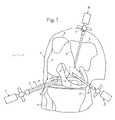
- FIG. 1shows a method of performing arthroscopic surgery on a patient.
- FIG. 2shows an atraumatic sheath for use with arthroscopic instruments.
- FIG. 2 ashows an atruamatic sheath having two tabs.
- FIG. 3shows an atraumatic sheath for use with arthroscopic instruments and an arthroscope disposed inside the atraumatic sheath.
- FIG. 4shows an atraumatic sheath for use with arthroscopic instruments, an arthroscope disposed inside the atraumatic sheath and an irrigation tube disposed on the sheath.
- FIG. 5shows a cross section of the atraumatic sheath shown in FIG. 2 and an arthroscopic instrument disposed inside the atraumatic sheath.
- FIG. 6shows an inflow/outflow atraumatic sheath for use with arthroscopic instruments.
- FIG. 7shows an inflow/outflow atraumatic sheath for use with arthroscopic instruments and an arthroscope disposed inside the atraumatic sheath.
- FIG. 8shows a cross section of the distal portion of the inflow/outflow atraumatic sheath of FIG. 7 .
- FIG. 9shows a cross section of the distal portion of an inflow/outflow atraumatic sheath.
- FIG. 10shows a cross section of the distal portion of an inflow/outflow atraumatic sheath.
- FIG. 11shows a cross section of the distal portion of an inflow/outflow atraumatic sheath.
- FIG. 12shows a cross section of the distal portion of an inflow/outflow atraumatic sheath.
- FIG. 13shows a cross section of the distal portion of an inflow/outflow atraumatic sheath.
- FIG. 14shows a cross section of the distal portion of an inflow/outflow atraumatic sheath.
- FIG. 15shows a cross section of the distal portion of an inflow/outflow atraumatic sheath.
- FIG. 16shows a cross section of the distal portion of an inflow/outflow atraumatic sheath.
- FIG. 17shows an inflow/outflow atraumatic sheath for use with arthroscopic instruments.
- FIG. 18shows a cross section of the distal portion of the inflow/outflow sheath shown in FIG. 17 .
- FIG. 19shows an inflow/outflow sheath having a distal portion that has an inner diameter that closely conforms to the outer diameter of the distal portion of an arthroscope.
- FIG. 20shows an atraumatic sheath and an elastic grip disposed on the proximal portion of the sheath.
- FIG. 21shows a cross section of an atraumatic sheath disposed over an arthroscope and an elastic grip disposed on the proximal portion of the sheath.
- FIG. 22shows a cross section of an atraumatic sheath disposed over an arthroscope, an elastic grip and levers disposed inside the grip.
- FIG. 23shows the distal end of the grip.
- FIG. 24shows the distal end of the grip and levers extending distally from the openings in the grip.
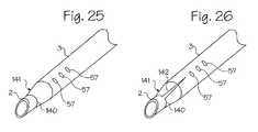
- FIG. 25shows the distal portion of an atraumatic sheath and an arthroscope extending distally of the distal end of the sheath.
- FIG. 26shows the distal portion of an atraumatic sheath and an arthroscope extending distally of the distal end of the sheath.
- FIG. 1shows a method of performing arthroscopic surgery on a patient by using an arthroscopic instrument 2 sheathed in an atraumatic introducer sheath 3 .
- An arthroscopic instrumentmay be an athroscope, endoscope, awl, pick, shaver, etc.
- the arthroscopic instrument 2 shownis an arthroscope.
- the various parts of the arthroscopeare shown in phantom to indicate their positions inside the sheath.
- Various anatomical landmarks in the patient's knee 4are shown for reference, including the femur 5 , patella 6 , posterior cruciate ligament 7 , anterior cruciate ligament 8 , meniscus 9 , tibia 10 and fibula 11 .
- the surgeonintroduces the arthroscope 2 into the knee via a first incision 12 in order to visualize the surgical field.
- a trimming instrument 13is introduced through a second incision 14 to remove or trim tissue that the surgeon determines should be removed or trimmed.
- an irrigating instrument 15may be introduced through a third incision 16 in order to irrigate the surgical field and thereby maintain a clear view.
- the irrigating instrumentmay be replaced by a combined arthroscope and inflow/outflow atraumatic sheath, thus reducing the number on incisions required to perform the surgery.
- the arthroscope 2is an optical instrument 17 surrounded by a rigid cannula 18 having a distal edge that typically is cut at an angle.
- the arthroscopehas been inserted into a resilient, outer introducer sheath or atraumatic sheath 3 that extends over the rigid cannula.
- the distal tip 19 of the atraumatic sheathextends distally just past the distal end of the arthroscope and rigid cannula to further protect the patient.
- FIGS. 2 through 4illustrate the atraumatic sheath 3 .
- the atraumatic sheathis a tube of a resilient material, such as a soft plastic or rubber.
- the inner diameter of the atraumatic sheathis sized and dimensioned to closely fit over the outer diameter of an arthroscopic instrument.
- the distal tip 19 of the atraumatic sheathis provided with a shape that closely approximates the shape of the distal tip of the arthroscope and/or the rigid cannula.
- a flange 30 disposed around the distal end of the sheathprevents the distal tip of the rigid cannula from gouging the patient.
- the flangeis integral with the walls of the sheath and extends inwardly towards the axis of the sheath.
- the flangeis sized and dimensioned to prevent the distal tip of the rigid cannula from accidentally slipping distally during a surgical procedure.
- An opening 36is provided in some atraumatic sheaths so that the surgeon may insert the endoscope or other instruments through the opening and into the surgical space.
- the distal lens 31 of an optical instrumentis shown for reference in FIGS. 3 and 4 .
- the proximal end 32 of the atraumatic sheathis provided with a tab 33 to allow medical personnel to easily pull the atraumatic sheath over the rigid cannula, arthroscope and/or arthroscopic instrument.
- the proximal end of the atraumatic sheathmay also be provided with fittings 38 , such as a locking hub or snap latches, that attach to fittings 39 or openings disposed on the arthroscope or other instrument, thereby securing the atraumatic sheath as illustrated in FIG. 7 .
- the tab 33is sized and dimensioned to divert liquids away from any device proximal the atraumatic sheath, such as cameras, optics, motors and other equipment that may be sensitive to liquids or moisture. Liquids that escapes the surgical site and that travel along the outer surface of the sheath will be deflected by the tab, which has a radial dimension greater than that of the lumen of the sheath.
- FIG. 2 ashows an atraumatic sheath 3 having two tabs 33 disposed along the longitudinal length of the sheath. If the flow of liquids is expected to be heavy for a surgical procedure, then the additional tab ensure that liquids do not reach sensitive devices located proximally of the sheath. Additional tabs may be provided along the longitudinal length of the sheath.
- the outer surface of the atraumatic sheathmay be provided with a smooth coating 40 as shown in FIG. 5 to allow the arthroscope and rigid cannula to more easily move within an operating site.
- the sheathmay be provided with a Teflon® (PTFE or expanded polytetrafluoroethylene) coating or covered with a water-activated lubricant.
- the inner surface of the atraumatic sheath(the walls that define the lumen of the tube) may be provided with a non-slip coating 41 or other high coefficient of friction coating.
- the inner surface of the atraumatic sheathmay be coated with a co-extruded tacky thermoplastic elastomer (TPE).
- TPEco-extruded tacky thermoplastic elastomer
- FIGS. 3 and 4show an atraumatic sheath 3 for use with arthroscopic instruments and an endoscope or arthroscope 2 disposed inside the atraumatic sheath.
- the atraumatic sheath shown in FIG. 3is provided with a balloon 34 on the distal portion of the sheath.
- the balloonmay be integrally formed with the sheath.
- the balloonallows a surgeon to open a space within tissue, thereby dissecting the surgical field.
- the arthroscopemay then be extended distally out of the opening 36 and the surgical space visualized.
- the distal end of the sheathmay be provided with a distally projecting spoon or other distally projecting object to prop open a space in front of the arthroscope.
- the balloon and the distally projecting spoonthus provide a means for dissecting or retracting tissue to form a small surgical space.
- FIG. 4shows an atraumatic sheath 3 having a second, working tube 35 .
- the working tubeallows irrigation, fiber optics, sutures, needles, probes or surgical tools through the lumen.
- the atraumatic sheath shown in FIG. 4may be combined with the atraumatic sheath shown in FIG. 3 to provide an atraumatic sheath with both a balloon and a working tube.
- FIG. 5shows a cross section of the atraumatic sheath 3 shown in FIG. 2 and an arthroscopic instrument 2 disposed inside the sheath.
- the atraumatic sheathis provided with a tab 33 on the proximal end of the sheath in order to increase the ease of pulling the sheath over the arthroscope.
- the distal end of the sheathis provided with an opening 36 to allow light to pass between the arthroscope and the operating space and, optionally, to allow additional instruments to pass through or alongside the arthroscope and into the surgical field.
- the walls 37 of the sheath at the distal end 19 of the sheathare thicker than the rest of the sheath walls to form a flange 30 at the distal end of the sheath.
- the flangemay be a separate ring of material attached to the inside of the sheath.
- the flangecovers the sharp distal tip of the arthroscopic instrument and prevents the instrument from slipping distally through opening 36 .
- the rest of the walls of the atraumatic sheathare thin in order to minimize the overall thickness of the combined sheath and arthroscopic instrument.
- the atraumatic sheathis provided and pulled over an arthroscopic instrument.
- the instrumentmay also be thought of as being inserted into the sheath.
- the sheathed arthroscopic instrumentis then inserted into the surgical site and the surgeon performs a medical procedure therein. If a balloon is provided, the balloon is used to dissect tissue so that the arthroscope may be extended distally out of the opening 36 and the surgical space visualized.
- FIGS. 6 and 7show an inflow/outflow atraumatic sheath 50 and an arthroscope 2 disposed inside the sheath.
- the inflow/outflow atraumatic sheath 50is formed of a resilient material that protects the patient from accidental injury should the arthroscope poke at or scrape along tissue.
- the sheath materialmay also be radiopaque.
- a preferred durometer hardness of the sheath materialis in the range of about 40 Shore D to about 90 Shore D. In this hardness range the sheath is sufficiently resilient that the sheath protects the patient from accidental injury but is sufficiently hard to prevent the lumens within sheath from collapsing.
- the inflow/outflow sheath 50is a multi-lumen tube into which an arthroscope is inserted. Each lumen extends from the distal portion 51 of the sheath to the proximal portion 52 of the sheath.
- the proximal portion of the sheathis provided with one or more fluid ports, such as first port 53 or second port 54 ; one or more stopcocks 55 or fluid switches; one or more valves, such as a check valve; a manifold 56 ; or other means of controlling the flow of fluid inside the sheath.
- the distal portion 51 of the inflow/outflow sheathis provided with a plurality of holes 57 . Each hole communicates with one or more of the lumens inside the tube, thereby allowing fluid to flow between the surgical field and the lumens inside the sheath.
- a surgeonmay cause a fluid, preferably saline, to flow from a fluid source 59 , through the arthroscope and into the surgical field, as shown by inflow arrows 60 .
- the arthroscopeis provided with one or more lumens, ports or working tubes that allow fluid to flow through the arthroscope and into the surgical field.
- blood, other fluids and debrisare drained from the surgical field through the holes 57 , as shown by outflow arrows 61 , and flow through one or more lumens in the sheath.
- the inflow of clear saline and the outflow of cloudy fluid and debrisallow the surgeon to maintain a clear surgical field using a single instrument. In turn, this capability eliminates the need to use an irrigating instrument.
- the surgeonmay have a clear field of view while using only a two-incision arthroscopic procedure.
- FIG. 7also shows that fluids are drained through the inflow/outflow atraumatic sheath by using a vacuum source 70 or gravity drain operatively attached to a fluid port, such as port 53 , connected to the sheath manifold 56 .
- Fluidsare provided through the arthroscope 2 from a fluid source 59 (by using a pump or gravity feed) operatively attached to a fluid port, such as third port 72 or fourth port 73 connected to the arthroscope.
- the vacuum source and fluid sourcemay be connected to different combinations of ports provided with the inflow/outflow sheath or the arthroscope.
- the vacuum sourcemay be attached to port 73 and the fluid source may be attached to port 72 on the inflow/outflow sheath.
- the surgeonmay both introduce fluids into and drain fluids from the surgical site using only the inflow/outflow sheath.
- the inflow/outflow sheathallows the surgeon to eliminate the need for the irrigation instrument.
- a pressure sensor, and flow rate control system and feedback control systemmay be provided to automatically monitor and control the rate of fluid flow into and out of the surgical site.
- FIG. 8shows a cross section of the distal portion of the inflow/outflow sheath 3 shown in FIG. 6 .
- the inflow/outflow sheath 50has a central lumen 80 , bounded by inner wall 81 , through which the arthroscope is inserted.
- the sheathhas four outer lumens, including a first outer lumen 82 , a second outer lumen 83 , a third outer lumen 84 and a fourth outer lumen 85 bounded by the inner wall 81 , the outer wall 86 and four relatively stiff ribs 87 that extend between the inner and outer walls and that run along the length of the sheath.
- the outer lumensare annular.
- the distal end of the sheath in the area of the outer lumens 82 , 83 , 84 and 85is sealed closed and provided with a rounded shape to help prevent injury to the patient (the central lumen remains open to accommodate the arthroscopic instrument). Holes 57 or apertures disposed in the outer wall allow fluids to flow into or out of the outer lumens.
- lumens 82 and 84could serve as passages through which fluids are introduced into the surgical site and lumens 83 and 85 could serve as passages through which fluids are drained from the surgical site.
- all four lumenscould be used to either drain or introduce fluids.
- the surgeonhas the option of using the inflow/outflow atraumatic sheath in many different modes.
- the sheathmay be formed with more than or fewer than the four ribs shown, so long as at least one outer lumen remains open to fluid flow after the sheath and scope have been inserted into the surgical site.
- FIGS. 9 through 16show cross sections of the distal portion of various inflow/outflow atraumatic sheaths.
- FIG. 9shows an inflow/outflow sheath having a second set of inner lumens, including a first inner lumen 100 , a second inner lumen 101 , a third inner lumen 102 and a fourth inner lumen 103 .
- the surgeoncan increase the rate of fluid exchange by using all of the inner lumens to introduce fluids into the surgical site and by using all of the outer lumens 82 , 83 , 84 and 85 to drain fluid from the surgical site (or visa versa).
- FIG. 10shows an inflow/outflow sheath 50 without an inner wall 81 .
- the outer surface 88 of the arthroscope 2serves as the inner wall of the sheath 50 once the arthroscope has been inserted into the sheath 2 .
- the four, relatively stiff ribs 87form a seal with the outer surface 88 of the arthroscope, thereby creating the four outer lumens 82 , 83 , 84 and 85 .
- the ends of the ribsmay be provided with elastic flanges 104 to enhance the seal made between the ribs 87 and the arthroscope 2 . This configuration reduces the overall size of the combined inflow/outflow sheath and arthroscope. (If the outer wall 86 is made of an elastomeric material, then the tube can stretch radially to accommodate a variety of sizes of arthroscopes.)
- FIG. 11shows an inflow/outflow atraumatic sheath 50 similar to that shown in FIG. 10 .
- the relatively hard ribs 87are pleated, but still form a seal with the outer wall of the arthroscope 2 , thereby forming the outer lumens 82 , 83 , 84 and 85 once the arthroscope is inserted into the sheath.
- the sheath of FIG. 11accommodates a variety of sizes of arthroscopes since the pleated ribs will bend to a degree necessary to accommodate larger sizes of arthroscopes, as shown in FIG. 12 .
- FIG. 13shows an inflow/outflow atraumatic sheath 50 similar to that shown in FIG. 11 .
- the ribs 87 of this sheathare elastic tubes that form a seal with the outer wall of the arthroscope 2 , thereby forming the outer lumens 82 , 83 , 84 and 85 once the arthroscope is inserted into the sheath.
- the sheath of FIG. 13accommodates a variety of sizes of arthroscopes since the tubes will compress to a degree necessary to accommodate larger sizes of arthroscopes, as shown in FIG. 14 .
- FIG. 15shows a “C”-shaped or slit inflow/outflow sheath 50 .
- four outer lumens 82 , 83 , 84 and 85are provided, with the outer lumens bounded by three ribs 87 , the inner wall 81 and the outer wall 86 .
- a small gap 105may form between the respective tips of the first arcuate segment 106 and the second arcuate segment 107 .
- tissue 108will seal the gap and prevent fluids from leaking from the surgical space to outside the body.
- the sheath of FIG. 15accommodates a variety of sizes of arthroscopes since the arcuate segments will move radially outwardly as a larger arthroscope is inserted into the sheath, as shown in FIG. 16 .
- a protrusion or a guide rail 109may extend from either the arthroscope or the sheath.
- the guide railhelps the user align the sheath on the arthroscope while inserting the arthroscope into the sheath.
- the guide railalso prevents unwanted rotation or twisting of the sheath over the arthroscope during a surgical procedure.
- FIGS. 17 and 18show an inflow/outflow atraumatic sheath 50 and an arthroscope 2 inserted into the sheath.
- the outer wall 86 of the distal portion 51 of the sheathis made from a continuous tube (the distal portion of the sheath is not provided with holes).
- the sheath of FIG. 17has an inner lumen to accommodate the arthroscope and four outer lumens to accommodate fluid inflow and outflow, including a first outer lumen 82 , a second outer lumen 83 , a third outer lumen 84 , and a fourth outer lumen 85 .
- the outer lumensare bounded by the inner wall 81 , outer wall 86 and supporting ribs 87 .
- the instrument shown in FIG. 17provides fluid inflow and outflow out of the distal end 110 of the sheath.
- FIG. 19shows an inflow/outflow atraumatic sheath 50 having a closely-conforming distal portion 111 that has an inner diameter that closely conforms to the outer diameter of the distal portion of an arthroscope 2 .
- the fluid-conducting portion 112 of the sheathis set proximally from the closely conforming distal portion 111 of the sheath.
- the outer diameter of the fluid conducting portion 112 and the outer diameter of the closely conforming distal portion 111may be formed integrally with each other such that both portions are part of the same sheath.
- Holes 57 disposed in the fluid-conducting portion 112 just proximally of the distal portion 111 of the sheathcommunicate with one or more lumens inside the sheath, thereby allowing a surgeon to either introduce or drain fluids from a surgical site.
- the sheath shown in FIG. 19has a distal portion 111 with a relatively small radius, since the sheath closely conforms to the arthroscope at the distal portion of the arthroscope. This provides the surgeon with the capability of inserting the arthroscope into narrow surgical sites.
- the fluid-conduction portionstill allows a surgeon to irrigate the surgical field with the combined sheath/arthroscope instrument.
- FIGS. 20 and 21show an atraumatic sheath 3 disposed over an arthroscope 2 and an elastic grip 120 disposed on the proximal portion 121 of the sheath.
- the grip 120is preferably a hollow, ergonomic cylinder of elastic material (such as a thermoplastic elastomer) that is sized and dimensioned to allow a surgeon to manipulate the arthroscope and sheath easily, even if the surgeon's hands become wet.
- the gripextends proximally of the proximal end 32 of the sheath so that the proximal portion 122 of the grip will extend over an arthroscope 2 disposed within the sheath 3 . (The proximal portion 121 of the sheath in FIG.
- the grip 20is shown in phantom to indicate its position inside the grip.
- the gripis designed such that the grip is biased to assume a shape having an inner diameter less than the outer diameter of the arthroscopic instrument and preferably less than the inner diameter of the sheath's inner lumen.
- the gripwill exert an inwardly directed radial force, as indicated by arrows 123 in FIG. 21 , against an instrument disposed within the sheath.
- the proximal portion 122 of the grip 120will squeeze down on and grasp an arthroscope 2 disposed within the sheath 3 . If the proximal portion of the grip is peeled back and released, the grip is biased to spring back to its original shape. Thus, the arthroscope will remain secure within the sheath as the arthroscope or sheath is manipulated during surgery.
- FIG. 22shows a cross section of an atraumatic sheath 3 disposed over an arthroscope 2 , an elastic grip 120 and levers 124 and 125 disposed inside the grip for widening the proximal opening of the grip.
- the grip shown in FIG. 22is provided with a first channel 126 and a second channel 127 into which a corresponding first lever 124 and second lever 125 have been inserted.
- the leversare provided with barbs, tangs or other means for securing the levers within their respective channels.
- the distal portions of the leversare provided with an arcuate shape such that the levers bend away from the sheath.
- a userpresses on the distal portions of the levers.
- the proximal portions of the leverswill exert a force directed radially outwardly against a corresponding segment of the proximal portion of the grip, thereby bending the proximal portion of the grip radially outwardly.
- This actionwidens the proximal opening of the grip.
- the usermay easily insert or remove the arthroscope from the sheath.
- Fulcrums 128 disposed on the distal portions of the leversprevent the levers from moving radially inwardly by more than a pre-determined amount. The fulcrums also allow a user to apply more outward force to corresponding segments in the proximal portion of the grip, thereby making the insertion of instruments easier.
- FIGS. 23 and 24show the distal end of the grip 120 and levers 124 and 125 extending from the distal end of the grip.
- a portion of the sheath 3is shown extending distally from the grip in FIG. 23 for reference.
- Channels 126 and 127 disposed in the gripextend longitudinally through (or partially through) the grip to accommodate the levers.
- a userpresses on the levers to peel back the proximal portion of the grip. The user then slides the arthroscope into or out of the sheath as desired.
- FIG. 25shows the distal portion of an atraumatic sheath 3 and an arthroscope 2 extending distally of the distal end 140 of the sheath 3 .
- Holes 57are provided in the distal portion of the sheath.
- the holescommunicate with one or more lumens in the sheath.
- the lumen or lumenscommunicate with a vacuum source, fluid source, therapeutic agent source or a combination of sources.
- the holesprovide for the inflow and outflow of fluids during a procedure.
- the distal tip 141 of the sheathis made of an elastic material having a higher modulus of elasticity than the modulus of elasticity found in the material of the proximal portion of the sheath.
- the sheath and the distal tip 141may be manufactured from a single flexible sterilizeable polymer.
- the distal tip of the sheathalso has an inner diameter that is slightly smaller than the outer diameter of most arthroscopes.
- the sheath and the distal tip 141may be manufactured from a single flexible sterilizeable polymer.
- a userinserts the arthroscope into the sheath.
- the distal tipexpands as the distal end of the arthroscope slides past the distal tip of the sheath. Because the inner diameter of the tip is less than the outer diameter of the arthroscope, the tip will form a fluid-proof seal with the arthroscope.
- FIG. 26shows the distal portion of an atraumatic sheath 3 and an arthroscope 2 extending distally of the distal end 140 of the sheath.
- Holes 57are provided in the sheath to allow the inflow and outflow of fluids during a surgical procedure.
- the distal tip 141 of the sheathis made of an elastic material having a hardness that is less than the hardness of the proximal portion of the sheath.
- a slit 142is provided in the tip and may extend into the distal portion of the sheath. In use, the slit and tip expand as a user slides an arthroscope through the tip. Thus, the slit allows the sheath to accommodate larger arthroscopes or other medical instruments.
- the sheathis also useful with other medical instruments and other surgical procedures in which it is desirable to protect surrounding tissue from accidental trauma.
- the atraumatic sheathmay be disposed over a trimming instrument for use during arthroscopic surgery or over an energy-delivering medical instrument, such as a laser or RF energy instrument.
- Other procedures in which the atraumatic sheath is usefulinclude laparoscopic surgery and other kinds of endoscopic surgery.
- the walls of sheathmay be provided with braided carbon fibers or a mesh of steel, plastic or other composite that resists bending.
Landscapes
- Health & Medical Sciences (AREA)
- Life Sciences & Earth Sciences (AREA)
- Surgery (AREA)
- Heart & Thoracic Surgery (AREA)
- Biomedical Technology (AREA)
- Engineering & Computer Science (AREA)
- Animal Behavior & Ethology (AREA)
- General Health & Medical Sciences (AREA)
- Public Health (AREA)
- Veterinary Medicine (AREA)
- Nuclear Medicine, Radiotherapy & Molecular Imaging (AREA)
- Medical Informatics (AREA)
- Molecular Biology (AREA)
- Pathology (AREA)
- Biophysics (AREA)
- Physics & Mathematics (AREA)
- Optics & Photonics (AREA)
- Radiology & Medical Imaging (AREA)
- Orthopedic Medicine & Surgery (AREA)
- Pulmonology (AREA)
- Anesthesiology (AREA)
- Hematology (AREA)
- Oral & Maxillofacial Surgery (AREA)
- Physical Education & Sports Medicine (AREA)
- Dentistry (AREA)
- Vascular Medicine (AREA)
- Endoscopes (AREA)
- Surgical Instruments (AREA)
Abstract
Description
Claims (12)
Priority Applications (13)
| Application Number | Priority Date | Filing Date | Title |
|---|---|---|---|
| US11/016,274US7435214B2 (en) | 2004-01-29 | 2004-12-17 | Atraumatic arthroscopic instrument sheath |
| PCT/US2005/002720WO2005072402A2 (en) | 2004-01-29 | 2005-01-28 | Atraumatic arthroscopic instrument sheath |
| JP2006551498AJP5025269B2 (en) | 2004-01-29 | 2005-01-28 | Noninvasive arthroscopy instrument sheath |
| EP05712239AEP1748722A4 (en) | 2004-01-29 | 2005-01-28 | Atraumatic arthroscopic instrument sheath |
| US11/094,626US7500947B2 (en) | 2004-01-29 | 2005-03-29 | Atraumatic arthroscopic instrument sheath |
| US12/251,351US8012083B2 (en) | 2004-01-29 | 2008-10-14 | Atraumatic arthroscopic instrument sheath |
| US12/401,451US8118731B2 (en) | 2004-01-29 | 2009-03-10 | Atraumatic arthroscopic instrument sheath |
| US13/225,908US8821387B2 (en) | 2004-01-29 | 2011-09-06 | Atraumatic arthroscopic instrument sheath |
| US13/401,500US8740773B2 (en) | 2004-01-29 | 2012-02-21 | Atraumatic arthroscopic instrument sheath |
| US14/294,612US9186044B2 (en) | 2004-01-29 | 2014-06-03 | Atraumatic arthroscopic instrument sheath |
| US14/475,378US9375207B2 (en) | 2004-01-29 | 2014-09-02 | Atraumatic arthroscopic instrument sheath |
| US14/944,083US9827009B2 (en) | 2004-01-29 | 2015-11-17 | Atraumatic arthroscopic instrument sheath |
| US15/195,825US20160374539A1 (en) | 2004-01-29 | 2016-06-28 | Atraumatic Arthroscopic Instrument Sheath |
Applications Claiming Priority (2)
| Application Number | Priority Date | Filing Date | Title |
|---|---|---|---|
| US10/769,629US7413542B2 (en) | 2004-01-29 | 2004-01-29 | Atraumatic arthroscopic instrument sheath |
| US11/016,274US7435214B2 (en) | 2004-01-29 | 2004-12-17 | Atraumatic arthroscopic instrument sheath |
Related Parent Applications (2)
| Application Number | Title | Priority Date | Filing Date |
|---|---|---|---|
| US10/769,629Continuation-In-PartUS7413542B2 (en) | 2004-01-29 | 2004-01-29 | Atraumatic arthroscopic instrument sheath |
| US10/769,629ContinuationUS7413542B2 (en) | 2004-01-29 | 2004-01-29 | Atraumatic arthroscopic instrument sheath |
Related Child Applications (2)
| Application Number | Title | Priority Date | Filing Date |
|---|---|---|---|
| US11/094,626Continuation-In-PartUS7500947B2 (en) | 2004-01-29 | 2005-03-29 | Atraumatic arthroscopic instrument sheath |
| US12/251,351ContinuationUS8012083B2 (en) | 2004-01-29 | 2008-10-14 | Atraumatic arthroscopic instrument sheath |
Publications (2)
| Publication Number | Publication Date |
|---|---|
| US20050192532A1 US20050192532A1 (en) | 2005-09-01 |
| US7435214B2true US7435214B2 (en) | 2008-10-14 |
Family
ID=46303529
Family Applications (5)
| Application Number | Title | Priority Date | Filing Date |
|---|---|---|---|
| US11/016,274Expired - LifetimeUS7435214B2 (en) | 2004-01-29 | 2004-12-17 | Atraumatic arthroscopic instrument sheath |
| US12/251,351Expired - LifetimeUS8012083B2 (en) | 2004-01-29 | 2008-10-14 | Atraumatic arthroscopic instrument sheath |
| US13/225,908Expired - LifetimeUS8821387B2 (en) | 2004-01-29 | 2011-09-06 | Atraumatic arthroscopic instrument sheath |
| US14/475,378Expired - LifetimeUS9375207B2 (en) | 2004-01-29 | 2014-09-02 | Atraumatic arthroscopic instrument sheath |
| US15/195,825AbandonedUS20160374539A1 (en) | 2004-01-29 | 2016-06-28 | Atraumatic Arthroscopic Instrument Sheath |
Family Applications After (4)
| Application Number | Title | Priority Date | Filing Date |
|---|---|---|---|
| US12/251,351Expired - LifetimeUS8012083B2 (en) | 2004-01-29 | 2008-10-14 | Atraumatic arthroscopic instrument sheath |
| US13/225,908Expired - LifetimeUS8821387B2 (en) | 2004-01-29 | 2011-09-06 | Atraumatic arthroscopic instrument sheath |
| US14/475,378Expired - LifetimeUS9375207B2 (en) | 2004-01-29 | 2014-09-02 | Atraumatic arthroscopic instrument sheath |
| US15/195,825AbandonedUS20160374539A1 (en) | 2004-01-29 | 2016-06-28 | Atraumatic Arthroscopic Instrument Sheath |
Country Status (1)
| Country | Link |
|---|---|
| US (5) | US7435214B2 (en) |
Cited By (20)
| Publication number | Priority date | Publication date | Assignee | Title |
|---|---|---|---|---|
| US20070208364A1 (en)* | 2006-03-02 | 2007-09-06 | Kms Development, Llc | Variably flexible insertion device and method for variably flexing an insertion device |
| US20080039691A1 (en)* | 2006-08-10 | 2008-02-14 | Kms Development, Llc | Torque-transmitting, variably-flexible, corrugated insertion device and method for transmitting torque and variably flexing a corrugated insertion device |
| US20080188715A1 (en)* | 2006-10-11 | 2008-08-07 | Olympus Medical Systems Corp. | Endoscope cleaning sheath, and endoscope apparatus and endoscope comprising the cleaning sheath |
| US20090005643A1 (en)* | 2007-06-27 | 2009-01-01 | Syntheon Llc | Torque-transmitting, variably-flexible, locking insertion device and method for operating the insertion device |
| US20100331822A1 (en)* | 2009-05-04 | 2010-12-30 | Benjamin Willemstyn | Multi-Component Sterile Connector Assembly and Anti-Slip Cover |
| US20110282152A1 (en)* | 2010-05-12 | 2011-11-17 | Q Park Medical Limited | Sheath for protecting endoscope probe |
| US20130269690A1 (en)* | 2010-10-07 | 2013-10-17 | Vitaltec Corporation | Inner Type Tracheostomy Tube |
| US8852091B2 (en) | 2012-04-04 | 2014-10-07 | Alcon Research, Ltd. | Devices, systems, and methods for pupil expansion |
| USD731652S1 (en) | 2014-02-19 | 2015-06-09 | Tidi Products, Llc | Dental curing light sleeve |
| US9119663B2 (en) | 2013-01-24 | 2015-09-01 | Hybrid Cannula LP | Hybrid cannula and methods for manufacturing the same |
| US9149294B2 (en) | 2013-01-24 | 2015-10-06 | Hybrid Cannula LP | Hybrid cannula and methods for manufacturing the same |
| US9155451B2 (en) | 2006-03-02 | 2015-10-13 | Syntheon, Llc | Variably flexible insertion device and method for variably flexing an insertion device |
| USD753290S1 (en)* | 2014-03-03 | 2016-04-05 | The Spectranetics Corporation | Sheath set |
| USD753289S1 (en)* | 2014-03-03 | 2016-04-05 | The Spectranetics Corporation | Sheath |
| US9433468B2 (en) | 2013-10-04 | 2016-09-06 | Tidi Products, Llc | Sheath for a medical or dental instrument |
| US9675371B2 (en) | 2014-03-03 | 2017-06-13 | The Spectranetics Corporation | Dilator sheath set |
| US10123683B2 (en) | 2006-03-02 | 2018-11-13 | Syntheon, Llc | Variably flexible insertion device and method for variably flexing an insertion device |
| US10159527B2 (en) | 2004-09-24 | 2018-12-25 | Syntheon, Llc | Selective stiffening catheter and methods for operating a selective stiffening catheter |
| US10751507B2 (en) | 2017-04-10 | 2020-08-25 | Syn Variflex, Llc | Thermally controlled variable-flexibility catheters and methods of manufacturing same |
| US11931070B1 (en) | 2020-01-30 | 2024-03-19 | Hybrid Cannula LP | Half pipe cannula and methods of manufacturing and using half pipe cannula |
Families Citing this family (67)
| Publication number | Priority date | Publication date | Assignee | Title |
|---|---|---|---|---|
| US20100137689A1 (en)* | 2001-09-19 | 2010-06-03 | Brannon James K | Laminar flow endoscope |
| US8506475B2 (en)* | 2001-09-19 | 2013-08-13 | James K. Brannon | Flexible scope endoscope |
| WO2005058207A1 (en) | 2003-12-11 | 2005-06-30 | Isto Technologies, Inc. | Particulate cartilage system |
| US7445596B2 (en)* | 2004-01-29 | 2008-11-04 | Cannuflow, Inc. | Atraumatic arthroscopic instrument sheath |
| US7500947B2 (en)* | 2004-01-29 | 2009-03-10 | Cannonflow, Inc. | Atraumatic arthroscopic instrument sheath |
| US7435214B2 (en)* | 2004-01-29 | 2008-10-14 | Cannuflow, Inc. | Atraumatic arthroscopic instrument sheath |
| US20120220821A1 (en)* | 2004-08-26 | 2012-08-30 | Brannon James K | Laminar Flow Endoscope |
| US20070005002A1 (en) | 2005-06-30 | 2007-01-04 | Intuitive Surgical Inc. | Robotic surgical instruments for irrigation, aspiration, and blowing |
| WO2007025290A2 (en) | 2005-08-26 | 2007-03-01 | Isto Technologies, Inc. | Implants and methods for repair, replacement and treatment of joint disease |
| US8235939B2 (en) | 2006-02-06 | 2012-08-07 | Kci Licensing, Inc. | System and method for purging a reduced pressure apparatus during the administration of reduced pressure treatment |
| US20070219585A1 (en)* | 2006-03-14 | 2007-09-20 | Cornet Douglas A | System for administering reduced pressure treatment having a manifold with a primary flow passage and a blockage prevention member |
| US9456860B2 (en) | 2006-03-14 | 2016-10-04 | Kci Licensing, Inc. | Bioresorbable foaming tissue dressing |
| US8163549B2 (en) | 2006-12-20 | 2012-04-24 | Zimmer Orthobiologics, Inc. | Method of obtaining viable small tissue particles and use for tissue repair |
| US20090012629A1 (en) | 2007-04-12 | 2009-01-08 | Isto Technologies, Inc. | Compositions and methods for tissue repair |
| US8226548B2 (en)* | 2007-07-07 | 2012-07-24 | Cannuflow, Inc. | Rigid arthroscope system |
| US20100022824A1 (en) | 2008-07-22 | 2010-01-28 | Cybulski James S | Tissue modification devices and methods of using the same |
| US20100121139A1 (en) | 2008-11-12 | 2010-05-13 | Ouyang Xiaolong | Minimally Invasive Imaging Systems |
| US8267891B2 (en)* | 2008-12-18 | 2012-09-18 | Alcon Research, Ltd. | Gilled phacoemulsification irrigation sleeve |
| CA2746525C (en) | 2008-12-31 | 2017-12-12 | Kci Licensing, Inc. | Manifolds, systems, and methods for administering reduced pressure to a subcutaneous tissue site |
| DE102011050173A1 (en)* | 2011-05-06 | 2012-11-08 | Vilmos Nagy | Stretchable introducer sheath and lock system |
| US10098703B2 (en) | 2011-08-16 | 2018-10-16 | Intuitive Surgical Operations, Inc. | Surgical instrument with commonly actuated robotic and manual features |
| US9387048B2 (en) | 2011-10-14 | 2016-07-12 | Intuitive Surgical Operations, Inc. | Catheter sensor systems |
| US20130303944A1 (en) | 2012-05-14 | 2013-11-14 | Intuitive Surgical Operations, Inc. | Off-axis electromagnetic sensor |
| US10238837B2 (en) | 2011-10-14 | 2019-03-26 | Intuitive Surgical Operations, Inc. | Catheters with control modes for interchangeable probes |
| US20130096385A1 (en)* | 2011-10-14 | 2013-04-18 | Intuitive Surgical Operations, Inc. | Vision probe and catheter systems |
| US9452276B2 (en) | 2011-10-14 | 2016-09-27 | Intuitive Surgical Operations, Inc. | Catheter with removable vision probe |
| EP2830515A2 (en)* | 2012-03-30 | 2015-02-04 | Koninklijke Philips N.V. | Nested cannula tips |
| US20140046137A1 (en)* | 2012-08-08 | 2014-02-13 | Ronda Duke Brown | Retractor Cover Apparatus and Associated Methods |
| JP2015226556A (en)* | 2012-09-25 | 2015-12-17 | テルモ株式会社 | Medical device |
| US20140178343A1 (en) | 2012-12-21 | 2014-06-26 | Jian Q. Yao | Supports and methods for promoting integration of cartilage tissue explants |
| WO2014122536A2 (en)* | 2013-02-07 | 2014-08-14 | Jet Prep Ltd. | Body passage device |
| EP2964113B1 (en) | 2013-03-08 | 2018-05-09 | Cannuflow, Inc. | Arthroscopic flexible portal cannula device and delivery system |
| US20140275768A1 (en)* | 2013-03-13 | 2014-09-18 | Covidien Lp | Thoracic Scope With Skirt And Gap |
| US20160199072A1 (en)* | 2013-08-19 | 2016-07-14 | Smith & Nephew, Inc. | Bone removal under direct visualization |
| US20150087911A1 (en) | 2013-09-26 | 2015-03-26 | Gyrus Acmi, Inc. D.B.A Olympus Surgical Technologies America | Endoscope sheath deflection devices |
| CN105848556B (en)* | 2013-10-21 | 2018-06-08 | 武汉佑康科技有限公司 | A kind of endoscope with cavity continuous perfusion and reflux function |
| US9370295B2 (en) | 2014-01-13 | 2016-06-21 | Trice Medical, Inc. | Fully integrated, disposable tissue visualization device |
| US11547446B2 (en) | 2014-01-13 | 2023-01-10 | Trice Medical, Inc. | Fully integrated, disposable tissue visualization device |
| US10342579B2 (en) | 2014-01-13 | 2019-07-09 | Trice Medical, Inc. | Fully integrated, disposable tissue visualization device |
| US10729419B2 (en) | 2014-10-23 | 2020-08-04 | Medos International Sarl | Biceps tenodesis implants and delivery tools |
| US10856966B2 (en) | 2014-10-23 | 2020-12-08 | Medos International Sarl | Biceps tenodesis implants and delivery tools |
| US10076374B2 (en) | 2014-10-23 | 2018-09-18 | Medos International Sárl | Biceps tenodesis delivery tools |
| US10751161B2 (en) | 2014-10-23 | 2020-08-25 | Medos International Sárl | Biceps tenodesis anchor implants |
| US10034742B2 (en) | 2014-10-23 | 2018-07-31 | Medos International Sarl | Biceps tenodesis implants and delivery tools |
| CN105662325B (en)* | 2014-11-24 | 2023-05-16 | 上海安清医疗器械有限公司 | Electronic laryngoscope |
| US9693856B2 (en) | 2015-04-22 | 2017-07-04 | DePuy Synthes Products, LLC | Biceps repair device |
| US10307042B2 (en) | 2015-04-28 | 2019-06-04 | Opportunity/Discovery Llc | Disposable sheath device |
| KR101751399B1 (en) | 2015-06-01 | 2017-06-27 | 주식회사 비에스코렘 | Egress cannula |
| EP3310241B1 (en)* | 2015-06-17 | 2020-08-05 | Covidien LP | Endoscopic device with drip flange |
| WO2017027749A1 (en) | 2015-08-11 | 2017-02-16 | Trice Medical, Inc. | Fully integrated, disposable tissue visualization device |
| EP3340852A2 (en)* | 2015-08-27 | 2018-07-04 | Boston Scientific Scimed Inc. | Medical devices and methods |
| US10537361B2 (en)* | 2016-01-29 | 2020-01-21 | Boston Scientific Limited | Access device having a fluid pathway and methods of using the same |
| US11006941B2 (en) | 2016-01-29 | 2021-05-18 | Boston Scientific Limited | Access device having an anchoring feature and methods of using the same |
| US10548633B2 (en) | 2016-02-26 | 2020-02-04 | Nanosurgery Technology Corporation | Video needle syringe |
| US10231824B2 (en) | 2016-04-08 | 2019-03-19 | Medos International Sárl | Tenodesis anchoring systems and tools |
| US10231823B2 (en) | 2016-04-08 | 2019-03-19 | Medos International Sarl | Tenodesis implants and tools |
| GB2553259B (en)* | 2016-05-17 | 2021-07-14 | Creo Medical Ltd | Control device for a surgical instrument |
| WO2018031978A1 (en)* | 2016-08-12 | 2018-02-15 | Bawa, Llc | Endoscope with secondary working channel |
| AU2016427268B2 (en)* | 2016-10-22 | 2022-07-07 | Opportunity / Discovery Llc | Disposable sheath device |
| US10987128B2 (en) | 2017-03-22 | 2021-04-27 | Covidien Lp | Cannula assembly |
| EP4491133A3 (en) | 2017-07-25 | 2025-03-12 | Stryker European Operations Holdings LLC | Irrigation sleeves for use with surgical systems |
| CN111093463A (en)* | 2017-09-28 | 2020-05-01 | 安布股份有限公司 | endoscope |
| US11172957B2 (en) | 2018-02-07 | 2021-11-16 | Stryker Corporation | Surgical cannula and methods of use |
| EP3773235B1 (en) | 2018-03-29 | 2023-07-19 | Trice Medical, Inc. | Fully integrated endoscope with biopsy capabilities |
| US10709317B2 (en)* | 2018-10-04 | 2020-07-14 | PraesidioDyne, LLC | Clamp assembly for disposable endoscopic sheaths |
| JP7078522B2 (en)* | 2018-11-19 | 2022-05-31 | 日機装株式会社 | Trocar |
| US11553830B1 (en)* | 2022-06-14 | 2023-01-17 | Izomed, Inc. | Endoscopic accessory |
Citations (43)
| Publication number | Priority date | Publication date | Assignee | Title |
|---|---|---|---|---|
| US4491132A (en) | 1982-08-06 | 1985-01-01 | Zimmer, Inc. | Sheath and retractable surgical tool combination |
| US4646722A (en) | 1984-12-10 | 1987-03-03 | Opielab, Inc. | Protective endoscope sheath and method of installing same |
| US4674500A (en) | 1985-09-27 | 1987-06-23 | Minnesota Mining And Manufacturing Company | Sheathed knife instrument |
| US4721097A (en) | 1986-10-31 | 1988-01-26 | Circon Corporation | Endoscope sheaths and method and apparatus for installation and removal |
| US4820265A (en) | 1986-12-16 | 1989-04-11 | Minnesota Mining And Manufacturing Company | Tubing set |
| US4886049A (en) | 1988-05-17 | 1989-12-12 | Darras Robert L | Medical instrument cover |
| US4897079A (en) | 1988-07-22 | 1990-01-30 | Allergan, Inc. | Polymeric sleeve for surgical instruments |
| US4973321A (en) | 1989-03-17 | 1990-11-27 | Michelson Gary K | Cannula for an arthroscope |
| US5184602A (en) | 1988-11-18 | 1993-02-09 | Effner Biomet Gmbh | Endoscope, in particular an arthroscope |
| US5273545A (en) | 1991-10-15 | 1993-12-28 | Apple Medical Corporation | Endoscopic cannula with tricuspid leaf valve |
| US5290279A (en) | 1991-12-19 | 1994-03-01 | Meditron Devices, Inc. | Arthroscopic tool combining five functions in one |
| US5337734A (en) | 1992-10-29 | 1994-08-16 | Advanced Polymers, Incorporated | Disposable sheath with optically transparent window formed continuously integral therewith |
| US5386817A (en) | 1991-06-10 | 1995-02-07 | Endomedical Technologies, Inc. | Endoscope sheath and valve system |
| US5413092A (en) | 1991-06-24 | 1995-05-09 | Xomed-Treace, Inc. | Sheath for endoscope |
| US5415157A (en) | 1993-02-05 | 1995-05-16 | Welcome; Steven | Damage preventing endoscope head cover |
| US5483951A (en) | 1994-02-25 | 1996-01-16 | Vision-Sciences, Inc. | Working channels for a disposable sheath for an endoscope |
| US5527276A (en) | 1993-01-12 | 1996-06-18 | Arthroscopic Assistants, Inc. | Flexible inflow/outflow cannula |
| US5571128A (en) | 1995-07-24 | 1996-11-05 | Shapiro; Henry | Safety surgical instrument |
| US5575756A (en) | 1993-08-16 | 1996-11-19 | Olympus Optical Co., Ltd. | Endoscope apparatus |
| US5575753A (en) | 1993-03-05 | 1996-11-19 | Olympus Optical Co., Ltd. | Endoscopic apparatus using a covered type endoscope fitted in an endoscope cover |
| US5643174A (en)* | 1993-08-18 | 1997-07-01 | Sumitomo Bakelite Company Limited | Endoscopic guide tube with embedded coil spring |
| US5667068A (en)* | 1995-06-13 | 1997-09-16 | Weaver; Stevie W. | Protective cover for an endoscope |
| US5762604A (en) | 1994-06-01 | 1998-06-09 | Archimedes Surgical, Inc. | Surgical instrument permitting endoscopic viewing and dissecting |
| US5924977A (en) | 1993-02-26 | 1999-07-20 | Olympus Optical Co., Ltd. | Endoscope system including endoscope and disposable protection cover |
| US5941815A (en)* | 1996-12-05 | 1999-08-24 | Helix Medical, Inc. | Sigmoid splint device for endoscopy |
| US5947990A (en) | 1997-02-24 | 1999-09-07 | Smith & Nephew, Inc. | Endoscopic surgical instrument |
| US5989183A (en) | 1993-07-22 | 1999-11-23 | Xomed Surgical Products, Inc. | Disposable endoscope sheath |
| US6110103A (en) | 1993-06-03 | 2000-08-29 | Xomed Surgical Products, Inc. | Disposable endoscope sheath |
| US6117068A (en)* | 1995-10-19 | 2000-09-12 | Elite Genetics, Inc | Artificial insemination system |
| US6120434A (en)* | 1994-08-29 | 2000-09-19 | Olympus Optical Co., Ltd. | Method of securing a cavity using a rigid sheath with transparent cap |
| US6126592A (en) | 1998-09-12 | 2000-10-03 | Smith & Nephew, Inc. | Endoscope cleaning and irrigation sheath |
| US6174280B1 (en) | 1998-11-19 | 2001-01-16 | Vision Sciences, Inc. | Sheath for protecting and altering the bending characteristics of a flexible endoscope |
| US6203537B1 (en) | 1999-02-04 | 2001-03-20 | Sorin Adrian | Laser-driven acoustic ablation catheter |
| US6269340B1 (en) | 1992-10-15 | 2001-07-31 | The General Hospital | Infusion pump with an electronically loadable drug library and a user interface for loading the library |
| US6293909B1 (en) | 1998-08-07 | 2001-09-25 | Scimed Life Systems, Inc. | Device and method of using a surgical assembly with mesh sheath |
| US6315714B1 (en) | 1998-11-30 | 2001-11-13 | Fuji Photo Optical Co., Ltd. | Endoscope insertion guide pipe |
| US6447446B1 (en) | 1999-11-02 | 2002-09-10 | Medtronic Xomed, Inc. | Method and apparatus for cleaning an endoscope lens |
| US20020173699A1 (en) | 2001-05-16 | 2002-11-21 | Stephen Becker | Endoscope sleeve and irrigation device |
| US20030018340A1 (en) | 2001-06-29 | 2003-01-23 | Branch Thomas P. | Method and apparatus for installing cannula |
| US6558379B1 (en) | 1999-11-18 | 2003-05-06 | Gyrus Medical Limited | Electrosurgical system |
| US20050043690A1 (en) | 2001-09-12 | 2005-02-24 | Stryker Corporation | Cannula that provides bi-directional fluid flow that is regulated by a single valve |
| US20050209506A1 (en)* | 2001-10-18 | 2005-09-22 | Atropos Limited | Device |
| US20050267331A1 (en)* | 2004-05-28 | 2005-12-01 | Secrest Dean J | Overtube assembly |
Family Cites Families (93)
| Publication number | Priority date | Publication date | Assignee | Title |
|---|---|---|---|---|
| US4026277A (en)* | 1974-04-12 | 1977-05-31 | Matsushita Electric Industrial Co., Ltd. | Blood pressure measuring apparatus |
| US4281645A (en)* | 1977-06-28 | 1981-08-04 | Duke University, Inc. | Method and apparatus for monitoring metabolism in body organs |
| JPS5444378A (en)* | 1977-09-14 | 1979-04-07 | Omron Tateisi Electronics Co | System of deciding minimum blood pressure in automatic blood pressure measuring device |
| US4320767A (en)* | 1980-04-07 | 1982-03-23 | Villa Real Antony Euclid C | Pocket-size electronic cuffless blood pressure and pulse rate calculator with optional temperature indicator, timer and memory |
| US4370696A (en)* | 1981-05-26 | 1983-01-25 | Miklos Darrell | Electrified glove |
| SE442377B (en)* | 1984-06-29 | 1985-12-23 | Mediplast Ab | CATS, HEALTH OR SIMILAR DEVICE |
| DE3500444C2 (en) | 1985-01-09 | 1986-10-16 | Aesculap-Werke Ag Vormals Jetter & Scheerer, 7200 Tuttlingen | Device for introducing an endoscope or a surgical tool into body cavities with a supply for a flushing medium and a suction device for this flushing medium |
| US4860761A (en)* | 1985-04-12 | 1989-08-29 | Omron Tateisi Electronics Co. | Pulse wave detecting apparatus for blood pressure measurement |
| US4800495A (en)* | 1986-08-18 | 1989-01-24 | Physio-Control Corporation | Method and apparatus for processing signals used in oximetry |
| US4766611A (en)* | 1987-07-31 | 1988-08-30 | Kim Young S | Glove and watch |
| US4825879A (en)* | 1987-10-08 | 1989-05-02 | Critkon, Inc. | Pulse oximeter sensor |
| US4807630A (en)* | 1987-10-09 | 1989-02-28 | Advanced Medical Systems, Inc. | Apparatus and method for use in pulse oximeters |
| JP3167968B2 (en) | 1987-10-22 | 2001-05-21 | 北陸電気工業株式会社 | Manufacturing method of chip resistor |
| US4951678A (en)* | 1988-05-23 | 1990-08-28 | Thomas Jefferson University | Methods and apparatus for monitoring vital signs |
| US4969879A (en)* | 1988-07-26 | 1990-11-13 | Gish Biomedical, Inc. | Body fluid interconnect |
| JPH0641535Y2 (en) | 1988-09-22 | 1994-11-02 | 富士写真光機株式会社 | Internal diagnosis / treatment device |
| USH1039H (en)* | 1988-11-14 | 1992-04-07 | The United States Of America As Represented By The Secretary Of The Air Force | Intrusion-free physiological condition monitoring |
| DE8814573U1 (en)* | 1988-11-18 | 1990-01-11 | BIOMET Deutschland GmbH, 14167 Berlin | endoscope |
| US4959058A (en)* | 1989-03-17 | 1990-09-25 | Michelson Gary K | Cannula having side opening |
| US5037386A (en)* | 1989-11-17 | 1991-08-06 | Minnesota Mining And Manufacturing Company | Pressure sensing scope cannula |
| JP2987452B2 (en)* | 1990-05-17 | 1999-12-06 | オリンパス光学工業株式会社 | Endoscope |
| GB9018390D0 (en) | 1990-08-22 | 1990-10-03 | Casale Enzo | Lavatory pan seat |
| US5140990A (en)* | 1990-09-06 | 1992-08-25 | Spacelabs, Inc. | Method of measuring blood pressure with a photoplethysmograph |
| US5329936A (en)* | 1991-02-04 | 1994-07-19 | Citation Medical Corporation | Portable arthroscope with periscope optics |
| US5213099A (en)* | 1991-09-30 | 1993-05-25 | The United States Of America As Represented By The Secretary Of The Air Force | Ear canal pulse/oxygen saturation measuring device |
| US5449356A (en)* | 1991-10-18 | 1995-09-12 | Birtcher Medical Systems, Inc. | Multifunctional probe for minimally invasive surgery |
| US5816676A (en)* | 1992-08-05 | 1998-10-06 | Koenen Myers; Howard P. | Work glove and illuminator assembly |
| US5351694A (en)* | 1992-11-16 | 1994-10-04 | Protocol Systems, Inc. | Noninvasive-blood-pressure (NIBP) monitoring apparatus with noninflatable, pressure-information-providing (PIP) structure |
| EP0600413A3 (en)* | 1992-11-30 | 1995-04-05 | Neuro Navigational Corp | Neuro endoscope for shunt. |
| CN1273077C (en)* | 1993-01-07 | 2006-09-06 | 精工爱普生株式会社 | Pulse wave analyser and diagnostic device using the same |
| ATE141481T1 (en)* | 1993-06-16 | 1996-09-15 | White Spot Ag | DEVICE FOR INTRODUCING FIBRIN GLUE INTO A STITCH CHANNEL |
| US5368039A (en)* | 1993-07-26 | 1994-11-29 | Moses; John A. | Method and apparatus for determining blood pressure |
| US5575284A (en)* | 1994-04-01 | 1996-11-19 | University Of South Florida | Portable pulse oximeter |
| JPH07289514A (en)* | 1994-04-25 | 1995-11-07 | I L:Kk | Front end lens washing pipe for endoscope |
| US5545150A (en)* | 1994-05-06 | 1996-08-13 | Endoscopic Concepts, Inc. | Trocar |
| US5655223A (en)* | 1994-06-16 | 1997-08-12 | Cozza; Frank C. | Electronic golf glove training device |
| US5524637A (en)* | 1994-06-29 | 1996-06-11 | Erickson; Jon W. | Interactive system for measuring physiological exertion |
| US5490523A (en)* | 1994-06-29 | 1996-02-13 | Nonin Medical Inc. | Finger clip pulse oximeter |
| US5651771A (en)* | 1994-11-07 | 1997-07-29 | Applied Medical Resources Corporation | Adjustable surgical clamp |
| US5919141A (en)* | 1994-11-15 | 1999-07-06 | Life Sensing Instrument Company, Inc. | Vital sign remote monitoring device |
| US5593394A (en)* | 1995-01-24 | 1997-01-14 | Kanesaka; Nozomu | Shaft for a catheter system |
| US5524617A (en)* | 1995-03-14 | 1996-06-11 | Nellcor, Incorporated | Isolated layer pulse oximetry |
| US5758644A (en)* | 1995-06-07 | 1998-06-02 | Masimo Corporation | Manual and automatic probe calibration |
| US5673436A (en)* | 1996-01-11 | 1997-10-07 | Piper; Stan | Defense glove |
| US6050940A (en)* | 1996-06-17 | 2000-04-18 | Cybernet Systems Corporation | General-purpose medical instrumentation |
| US5797882A (en)* | 1996-08-23 | 1998-08-25 | Becton Dickinson And Company | Arterial catheter and catheter/needle assembly with improved flow characteristics and method for its use |
| US6018673A (en)* | 1996-10-10 | 2000-01-25 | Nellcor Puritan Bennett Incorporated | Motion compatible sensor for non-invasive optical blood analysis |
| US5830137A (en)* | 1996-11-18 | 1998-11-03 | University Of South Florida | Green light pulse oximeter |
| US6827710B1 (en)* | 1996-11-26 | 2004-12-07 | Edwards Lifesciences Corporation | Multiple lumen access device |
| USD393934S (en)* | 1996-12-17 | 1998-04-28 | Nike, Inc. | Glove |
| US5931791A (en)* | 1997-11-05 | 1999-08-03 | Instromedix, Inc. | Medical patient vital signs-monitoring apparatus |
| US6280190B1 (en)* | 1998-01-28 | 2001-08-28 | Elliott S. Hoffman | Dental saliva ejector tube assembly |
| US6474990B2 (en)* | 1998-01-28 | 2002-11-05 | Elliott S. Hoffman | Dental saliva ejector tube assembly |
| US6159160A (en)* | 1998-03-26 | 2000-12-12 | Ethicon, Inc. | System and method for controlled infusion and pressure monitoring |
| US6272364B1 (en)* | 1998-05-13 | 2001-08-07 | Cygnus, Inc. | Method and device for predicting physiological values |
| US6519486B1 (en)* | 1998-10-15 | 2003-02-11 | Ntc Technology Inc. | Method, apparatus and system for removing motion artifacts from measurements of bodily parameters |
| WO2000048505A1 (en)* | 1999-02-18 | 2000-08-24 | Karl Storz Gmbh & Co. Kg | Endoscope |
| US6344025B1 (en)* | 1999-02-19 | 2002-02-05 | Omron Corporation | Blood pressure monitor |
| US6336900B1 (en)* | 1999-04-12 | 2002-01-08 | Agilent Technologies, Inc. | Home hub for reporting patient health parameters |
| US6257626B1 (en)* | 1999-04-27 | 2001-07-10 | Flow-Rite Controls, Ltd. | Connector for fluid handling system |
| US6126572A (en)* | 1999-05-19 | 2000-10-03 | Carl M. Smith | Apparatus for monitoring and displaying exertion data |
| US6413223B1 (en)* | 1999-06-01 | 2002-07-02 | Massachussetts Institute Of Technology | Cuffless continuous blood pressure monitor |
| US6454702B1 (en)* | 1999-10-14 | 2002-09-24 | Scimed Life Systems, Inc. | Endoscope and endoscopic instrument system having reduced backlash when moving the endoscopic instrument within a working channel of the endoscope |
| US6612984B1 (en)* | 1999-12-03 | 2003-09-02 | Kerr, Ii Robert A. | System and method for collecting and transmitting medical data |
| WO2001054575A1 (en)* | 2000-01-26 | 2001-08-02 | Vsm Medtech Ltd. | Continuous blood pressure monitoring method and apparatus |
| US6808505B2 (en)* | 2000-02-01 | 2004-10-26 | Kadan Jeffrey S | Diagnostic needle arthroscopy and lavage system |
| US6385821B1 (en)* | 2000-02-17 | 2002-05-14 | Udt Sensors, Inc. | Apparatus for securing an oximeter probe to a patient |
| US6616613B1 (en)* | 2000-04-27 | 2003-09-09 | Vitalsines International, Inc. | Physiological signal monitoring system |
| US6533729B1 (en)* | 2000-05-10 | 2003-03-18 | Motorola Inc. | Optical noninvasive blood pressure sensor and method |
| US6605038B1 (en)* | 2000-06-16 | 2003-08-12 | Bodymedia, Inc. | System for monitoring health, wellness and fitness |
| US6239410B1 (en)* | 2000-07-14 | 2001-05-29 | Allan Tackore | Glove with incorporated adjustable heater |
| US6269487B1 (en)* | 2000-08-09 | 2001-08-07 | Barbara E. Schryver | Tennis glove |
| US6434408B1 (en)* | 2000-09-29 | 2002-08-13 | Datex-Ohmeda, Inc. | Pulse oximetry method and system with improved motion correction |
| US6585639B1 (en)* | 2000-10-27 | 2003-07-01 | Pulmonx | Sheath and method for reconfiguring lung viewing scope |
| US6556852B1 (en)* | 2001-03-27 | 2003-04-29 | I-Medik, Inc. | Earpiece with sensors to measure/monitor multiple physiological variables |
| US6808473B2 (en)* | 2001-04-19 | 2004-10-26 | Omron Corporation | Exercise promotion device, and exercise promotion method employing the same |
| WO2003009680A1 (en)* | 2001-07-24 | 2003-02-06 | The Regents Of The University Of Michigan | Electronic measurement of the motion of a moving body of sports equipment |
| JP3668843B2 (en)* | 2001-08-27 | 2005-07-06 | オムロンヘルスケア株式会社 | Electronic blood pressure monitor and blood pressure measurement data processing system |
| US6692431B2 (en)* | 2001-09-07 | 2004-02-17 | Smith & Nephew, Inc. | Endoscopic system with a solid-state light source |
| US6401254B1 (en)* | 2001-09-28 | 2002-06-11 | David W. Boller | Device for wearing on a hand and counting and displaying golf strokes taken per hole per game |
| US6592235B1 (en)* | 2002-02-22 | 2003-07-15 | Gary Mayo | Light emitting glove |
| US6702752B2 (en)* | 2002-02-22 | 2004-03-09 | Datex-Ohmeda, Inc. | Monitoring respiration based on plethysmographic heart rate signal |
| US6878149B2 (en)* | 2002-03-25 | 2005-04-12 | Acueity, Inc. | Apparatus and method for intraductal abalation |
| US6708136B1 (en)* | 2002-07-12 | 2004-03-16 | Barbara A. Lahiff | Electronic data system for use with sporting impliments |
| US6799226B1 (en)* | 2002-07-23 | 2004-09-28 | Apple Computer, Inc. | Hot unpluggable media storage device |
| US6879850B2 (en)* | 2002-08-16 | 2005-04-12 | Optical Sensors Incorporated | Pulse oximeter with motion detection |
| US6609023B1 (en)* | 2002-09-20 | 2003-08-19 | Angel Medical Systems, Inc. | System for the detection of cardiac events |
| US6760923B1 (en)* | 2003-02-11 | 2004-07-13 | Origen Biomedical | Glove with flexible joints |
| JP2005033019A (en) | 2003-07-04 | 2005-02-03 | Sumitomo Electric Ind Ltd | Light emitting module |
| US7150713B2 (en)* | 2003-10-16 | 2006-12-19 | Smith & Nephew, Inc. | Endoscopic device |
| WO2005072402A2 (en) | 2004-01-29 | 2005-08-11 | Cannuflow, Inc. | Atraumatic arthroscopic instrument sheath |
| US7435214B2 (en)* | 2004-01-29 | 2008-10-14 | Cannuflow, Inc. | Atraumatic arthroscopic instrument sheath |
| US20060041186A1 (en)* | 2004-08-17 | 2006-02-23 | Vancaillie Thierry G | Continuous flow single sheath for endoscope |
- 2004
- 2004-12-17USUS11/016,274patent/US7435214B2/ennot_activeExpired - Lifetime
- 2008
- 2008-10-14USUS12/251,351patent/US8012083B2/ennot_activeExpired - Lifetime
- 2011
- 2011-09-06USUS13/225,908patent/US8821387B2/ennot_activeExpired - Lifetime
- 2014
- 2014-09-02USUS14/475,378patent/US9375207B2/ennot_activeExpired - Lifetime
- 2016
- 2016-06-28USUS15/195,825patent/US20160374539A1/ennot_activeAbandoned
Patent Citations (44)
| Publication number | Priority date | Publication date | Assignee | Title |
|---|---|---|---|---|
| US4491132A (en) | 1982-08-06 | 1985-01-01 | Zimmer, Inc. | Sheath and retractable surgical tool combination |
| US4646722A (en) | 1984-12-10 | 1987-03-03 | Opielab, Inc. | Protective endoscope sheath and method of installing same |
| US4674500A (en) | 1985-09-27 | 1987-06-23 | Minnesota Mining And Manufacturing Company | Sheathed knife instrument |
| US4721097A (en) | 1986-10-31 | 1988-01-26 | Circon Corporation | Endoscope sheaths and method and apparatus for installation and removal |
| US4820265A (en) | 1986-12-16 | 1989-04-11 | Minnesota Mining And Manufacturing Company | Tubing set |
| US4886049A (en) | 1988-05-17 | 1989-12-12 | Darras Robert L | Medical instrument cover |
| US4897079A (en) | 1988-07-22 | 1990-01-30 | Allergan, Inc. | Polymeric sleeve for surgical instruments |
| US5184602A (en) | 1988-11-18 | 1993-02-09 | Effner Biomet Gmbh | Endoscope, in particular an arthroscope |
| US4973321A (en) | 1989-03-17 | 1990-11-27 | Michelson Gary K | Cannula for an arthroscope |
| US5386817A (en) | 1991-06-10 | 1995-02-07 | Endomedical Technologies, Inc. | Endoscope sheath and valve system |
| US5413092A (en) | 1991-06-24 | 1995-05-09 | Xomed-Treace, Inc. | Sheath for endoscope |
| US5273545A (en) | 1991-10-15 | 1993-12-28 | Apple Medical Corporation | Endoscopic cannula with tricuspid leaf valve |
| US5290279A (en) | 1991-12-19 | 1994-03-01 | Meditron Devices, Inc. | Arthroscopic tool combining five functions in one |
| US6269340B1 (en) | 1992-10-15 | 2001-07-31 | The General Hospital | Infusion pump with an electronically loadable drug library and a user interface for loading the library |
| US5337734A (en) | 1992-10-29 | 1994-08-16 | Advanced Polymers, Incorporated | Disposable sheath with optically transparent window formed continuously integral therewith |
| US5527276A (en) | 1993-01-12 | 1996-06-18 | Arthroscopic Assistants, Inc. | Flexible inflow/outflow cannula |
| US5800409A (en) | 1993-01-12 | 1998-09-01 | Arthroscopic Assistants, Inc. | Flexible inflow/outflow cannula |
| US5415157A (en) | 1993-02-05 | 1995-05-16 | Welcome; Steven | Damage preventing endoscope head cover |
| US5924977A (en) | 1993-02-26 | 1999-07-20 | Olympus Optical Co., Ltd. | Endoscope system including endoscope and disposable protection cover |
| US5575753A (en) | 1993-03-05 | 1996-11-19 | Olympus Optical Co., Ltd. | Endoscopic apparatus using a covered type endoscope fitted in an endoscope cover |
| US6110103A (en) | 1993-06-03 | 2000-08-29 | Xomed Surgical Products, Inc. | Disposable endoscope sheath |
| US5989183A (en) | 1993-07-22 | 1999-11-23 | Xomed Surgical Products, Inc. | Disposable endoscope sheath |
| US5575756A (en) | 1993-08-16 | 1996-11-19 | Olympus Optical Co., Ltd. | Endoscope apparatus |
| US5643174A (en)* | 1993-08-18 | 1997-07-01 | Sumitomo Bakelite Company Limited | Endoscopic guide tube with embedded coil spring |
| US5483951A (en) | 1994-02-25 | 1996-01-16 | Vision-Sciences, Inc. | Working channels for a disposable sheath for an endoscope |
| US5762604A (en) | 1994-06-01 | 1998-06-09 | Archimedes Surgical, Inc. | Surgical instrument permitting endoscopic viewing and dissecting |
| US6120434A (en)* | 1994-08-29 | 2000-09-19 | Olympus Optical Co., Ltd. | Method of securing a cavity using a rigid sheath with transparent cap |
| US5667068A (en)* | 1995-06-13 | 1997-09-16 | Weaver; Stevie W. | Protective cover for an endoscope |
| US5571128A (en) | 1995-07-24 | 1996-11-05 | Shapiro; Henry | Safety surgical instrument |
| US6117068A (en)* | 1995-10-19 | 2000-09-12 | Elite Genetics, Inc | Artificial insemination system |
| US5941815A (en)* | 1996-12-05 | 1999-08-24 | Helix Medical, Inc. | Sigmoid splint device for endoscopy |
| US5947990A (en) | 1997-02-24 | 1999-09-07 | Smith & Nephew, Inc. | Endoscopic surgical instrument |
| US6293909B1 (en) | 1998-08-07 | 2001-09-25 | Scimed Life Systems, Inc. | Device and method of using a surgical assembly with mesh sheath |
| US6126592A (en) | 1998-09-12 | 2000-10-03 | Smith & Nephew, Inc. | Endoscope cleaning and irrigation sheath |
| US6174280B1 (en) | 1998-11-19 | 2001-01-16 | Vision Sciences, Inc. | Sheath for protecting and altering the bending characteristics of a flexible endoscope |
| US6315714B1 (en) | 1998-11-30 | 2001-11-13 | Fuji Photo Optical Co., Ltd. | Endoscope insertion guide pipe |
| US6203537B1 (en) | 1999-02-04 | 2001-03-20 | Sorin Adrian | Laser-driven acoustic ablation catheter |
| US6447446B1 (en) | 1999-11-02 | 2002-09-10 | Medtronic Xomed, Inc. | Method and apparatus for cleaning an endoscope lens |
| US6558379B1 (en) | 1999-11-18 | 2003-05-06 | Gyrus Medical Limited | Electrosurgical system |
| US20020173699A1 (en) | 2001-05-16 | 2002-11-21 | Stephen Becker | Endoscope sleeve and irrigation device |
| US20030018340A1 (en) | 2001-06-29 | 2003-01-23 | Branch Thomas P. | Method and apparatus for installing cannula |
| US20050043690A1 (en) | 2001-09-12 | 2005-02-24 | Stryker Corporation | Cannula that provides bi-directional fluid flow that is regulated by a single valve |
| US20050209506A1 (en)* | 2001-10-18 | 2005-09-22 | Atropos Limited | Device |
| US20050267331A1 (en)* | 2004-05-28 | 2005-12-01 | Secrest Dean J | Overtube assembly |
Non-Patent Citations (1)
| Title |
|---|
| Linvatek Product Brochure, Spring/Summer Edition 2000. |
Cited By (39)
| Publication number | Priority date | Publication date | Assignee | Title |
|---|---|---|---|---|
| US10463427B2 (en) | 2004-09-24 | 2019-11-05 | Syn Variflex, Llc | Selective stiffening catheter |
| US11382690B2 (en) | 2004-09-24 | 2022-07-12 | Syn Variflex, Llc | Selective stiffening catheter |
| US11376065B2 (en) | 2004-09-24 | 2022-07-05 | Syn Variflex, Llc | Selective stiffening catheter |
| US10159527B2 (en) | 2004-09-24 | 2018-12-25 | Syntheon, Llc | Selective stiffening catheter and methods for operating a selective stiffening catheter |
| US8092374B2 (en) | 2006-03-02 | 2012-01-10 | Kevin Smith | Variably flexible insertion device and method for variably flexing an insertion device |
| US20070208364A1 (en)* | 2006-03-02 | 2007-09-06 | Kms Development, Llc | Variably flexible insertion device and method for variably flexing an insertion device |
| US10123683B2 (en) | 2006-03-02 | 2018-11-13 | Syntheon, Llc | Variably flexible insertion device and method for variably flexing an insertion device |
| US10835112B2 (en) | 2006-03-02 | 2020-11-17 | Syntheon, Llc | Variably flexible insertion device and method for variably flexing an insertion device |
| US8696639B2 (en) | 2006-03-02 | 2014-04-15 | Syntheon, Llc | Variably flexible insertion device and method for variably flexing an insertion device |
| US9155451B2 (en) | 2006-03-02 | 2015-10-13 | Syntheon, Llc | Variably flexible insertion device and method for variably flexing an insertion device |
| US20110130628A1 (en)* | 2006-08-10 | 2011-06-02 | Smith Kevin W | Method for Transmitting Torque and Variably Flexing a Corrugated Insertion Device |
| US8298137B2 (en) | 2006-08-10 | 2012-10-30 | Syntheon, Llc | Method for transmitting torque and variably flexing a corrugated insertion device |
| US8292802B2 (en) | 2006-08-10 | 2012-10-23 | Syntheon, Llc | Method for transmitting torque and variably flexing a corrugated insertion device |
| US20080039691A1 (en)* | 2006-08-10 | 2008-02-14 | Kms Development, Llc | Torque-transmitting, variably-flexible, corrugated insertion device and method for transmitting torque and variably flexing a corrugated insertion device |
| US8708894B2 (en) | 2006-08-10 | 2014-04-29 | Syntheon, Llc | Method for variably flexing and steering an insertion device |
| US7988621B2 (en) | 2006-08-10 | 2011-08-02 | Syntheon, Llc | Torque-transmitting, variably-flexible, corrugated insertion device and method for transmitting torque and variably flexing a corrugated insertion device |
| US8079952B2 (en)* | 2006-10-11 | 2011-12-20 | Olympus Medical Systems Corp | Endoscope cleaning sheath, and endoscope apparatus and endoscope comprising the cleaning sheath |
| US20080188715A1 (en)* | 2006-10-11 | 2008-08-07 | Olympus Medical Systems Corp. | Endoscope cleaning sheath, and endoscope apparatus and endoscope comprising the cleaning sheath |
| US9814372B2 (en)* | 2007-06-27 | 2017-11-14 | Syntheon, Llc | Torque-transmitting, variably-flexible, locking insertion device and method for operating the insertion device |
| US20090005643A1 (en)* | 2007-06-27 | 2009-01-01 | Syntheon Llc | Torque-transmitting, variably-flexible, locking insertion device and method for operating the insertion device |
| US10806331B2 (en) | 2007-06-27 | 2020-10-20 | Syntheon, Llc | Torque-transmitting, variably-flexible, locking insertion device and method for operating the insertion device |
| US20100331822A1 (en)* | 2009-05-04 | 2010-12-30 | Benjamin Willemstyn | Multi-Component Sterile Connector Assembly and Anti-Slip Cover |
| US20110282152A1 (en)* | 2010-05-12 | 2011-11-17 | Q Park Medical Limited | Sheath for protecting endoscope probe |
| US20130269690A1 (en)* | 2010-10-07 | 2013-10-17 | Vitaltec Corporation | Inner Type Tracheostomy Tube |
| US9433739B2 (en)* | 2010-10-07 | 2016-09-06 | Vitaltec Corporation | Inner type tracheostomy tube |
| US8852091B2 (en) | 2012-04-04 | 2014-10-07 | Alcon Research, Ltd. | Devices, systems, and methods for pupil expansion |
| US10149699B2 (en) | 2013-01-24 | 2018-12-11 | Hybrid Cannula LP | Hybrid cannula and methods for manufacturing the same |
| US9119663B2 (en) | 2013-01-24 | 2015-09-01 | Hybrid Cannula LP | Hybrid cannula and methods for manufacturing the same |
| US9149294B2 (en) | 2013-01-24 | 2015-10-06 | Hybrid Cannula LP | Hybrid cannula and methods for manufacturing the same |
| US9398924B2 (en) | 2013-01-24 | 2016-07-26 | Hybrid Cannula LP | Hybrid cannula and methods for manufacturing the same |
| US9314269B2 (en) | 2013-01-24 | 2016-04-19 | Hybrid Cannula LP | Hybrid cannula and methods for manufacturing the same |
| US9433468B2 (en) | 2013-10-04 | 2016-09-06 | Tidi Products, Llc | Sheath for a medical or dental instrument |
| USD731652S1 (en) | 2014-02-19 | 2015-06-09 | Tidi Products, Llc | Dental curing light sleeve |
| US9675371B2 (en) | 2014-03-03 | 2017-06-13 | The Spectranetics Corporation | Dilator sheath set |
| US10653867B2 (en) | 2014-03-03 | 2020-05-19 | Spectranetics Llc | Dilator sheath set |
| USD753289S1 (en)* | 2014-03-03 | 2016-04-05 | The Spectranetics Corporation | Sheath |
| USD753290S1 (en)* | 2014-03-03 | 2016-04-05 | The Spectranetics Corporation | Sheath set |
| US10751507B2 (en) | 2017-04-10 | 2020-08-25 | Syn Variflex, Llc | Thermally controlled variable-flexibility catheters and methods of manufacturing same |
| US11931070B1 (en) | 2020-01-30 | 2024-03-19 | Hybrid Cannula LP | Half pipe cannula and methods of manufacturing and using half pipe cannula |
Also Published As
| Publication number | Publication date |
|---|---|
| US20160374539A1 (en) | 2016-12-29 |
| US9375207B2 (en) | 2016-06-28 |
| US8821387B2 (en) | 2014-09-02 |
| US20120116164A1 (en) | 2012-05-10 |
| US20090043165A1 (en) | 2009-02-12 |
| US20150087906A1 (en) | 2015-03-26 |
| US8012083B2 (en) | 2011-09-06 |
| US20050192532A1 (en) | 2005-09-01 |
Similar Documents
| Publication | Publication Date | Title |
|---|---|---|
| US9375207B2 (en) | Atraumatic arthroscopic instrument sheath | |
| US9872604B2 (en) | Atraumatic arthroscopic instrument sheath and method | |
| US12226076B2 (en) | Rigid endoscope system | |
| US9364204B2 (en) | Atraumatic arthroscopic instrument sheath | |
| JP5025269B2 (en) | Noninvasive arthroscopy instrument sheath | |
| EP1983881B1 (en) | Anti-extravasation sheath |
Legal Events
| Date | Code | Title | Description |
|---|---|---|---|
| AS | Assignment | Owner name:CANNUFLOW INCORPORATED, CALIFORNIA Free format text:ASSIGNMENT OF ASSIGNORS INTEREST;ASSIGNORS:KUCKLICK, THEODORE R.;TRIEB, MARTIN, M.D.;REEL/FRAME:021504/0692 Effective date:20040805 | |
| STCF | Information on status: patent grant | Free format text:PATENTED CASE | |
| FPAY | Fee payment | Year of fee payment:4 | |
| FPAY | Fee payment | Year of fee payment:8 | |
| MAFP | Maintenance fee payment | Free format text:PAYMENT OF MAINTENANCE FEE, 12TH YR, SMALL ENTITY (ORIGINAL EVENT CODE: M2553); ENTITY STATUS OF PATENT OWNER: SMALL ENTITY Year of fee payment:12 | |
| AS | Assignment | Owner name:PRISTINE SURGICAL LLC, NEW HAMPSHIRE Free format text:ASSIGNMENT OF ASSIGNORS INTEREST;ASSIGNOR:CANNUFLOW, INC.;REEL/FRAME:053594/0011 Effective date:20200611 | |
| AS | Assignment | Owner name:PINEY LAKE OPPORTUNITIES ECI MASTER FUND LP, AS AGENT, CONNECTICUT Free format text:SECURITY INTEREST;ASSIGNOR:PRISTINE SURGICAL LLC;REEL/FRAME:056765/0708 Effective date:20210702 | |
| AS | Assignment | Owner name:PSIP2 LLC, NEW HAMPSHIRE Free format text:ASSIGNMENT OF ASSIGNORS INTEREST;ASSIGNOR:PRISTINE SURGICAL LLC;REEL/FRAME:060254/0452 Effective date:20220601 | |
| AS | Assignment | Owner name:PINEY LAKE OPPORTUNITIES ECI MASTER FUND LP, AS COLLATERAL AGENT, CONNECTICUT Free format text:SECURITY INTEREST;ASSIGNOR:PSIP2 LLC;REEL/FRAME:061006/0252 Effective date:20220728 |