US7433715B2 - Mobile station for telecommunications system - Google Patents
Mobile station for telecommunications systemDownload PDFInfo
- Publication number
- US7433715B2 US7433715B2US09/854,256US85425601AUS7433715B2US 7433715 B2US7433715 B2US 7433715B2US 85425601 AUS85425601 AUS 85425601AUS 7433715 B2US7433715 B2US 7433715B2
- Authority
- US
- United States
- Prior art keywords
- handset
- call
- audio
- switch
- headset
- Prior art date
- Legal status (The legal status is an assumption and is not a legal conclusion. Google has not performed a legal analysis and makes no representation as to the accuracy of the status listed.)
- Expired - Fee Related, expires
Links
- 230000000977initiatory effectEffects0.000claimsabstractdescription10
- 230000005236sound signalEffects0.000claimsabstractdescription7
- 230000000694effectsEffects0.000claimsabstractdescription4
- 238000000034methodMethods0.000claimsdescription14
- 238000012544monitoring processMethods0.000claimsdescription4
- 230000008859changeEffects0.000claimsdescription3
- 238000001514detection methodMethods0.000claimsdescription2
- 230000000994depressogenic effectEffects0.000description6
- 210000003128headAnatomy0.000description5
- 230000009977dual effectEffects0.000description4
- 230000007246mechanismEffects0.000description4
- 230000009471actionEffects0.000description1
- 230000002411adverseEffects0.000description1
- 230000008878couplingEffects0.000description1
- 238000010168coupling processMethods0.000description1
- 238000005859coupling reactionMethods0.000description1
- 238000010586diagramMethods0.000description1
- 210000000613ear canalAnatomy0.000description1
- 230000008569processEffects0.000description1
Images


Classifications
- H—ELECTRICITY
- H04—ELECTRIC COMMUNICATION TECHNIQUE
- H04M—TELEPHONIC COMMUNICATION
- H04M1/00—Substation equipment, e.g. for use by subscribers
- H04M1/60—Substation equipment, e.g. for use by subscribers including speech amplifiers
- H04M1/6033—Substation equipment, e.g. for use by subscribers including speech amplifiers for providing handsfree use or a loudspeaker mode in telephone sets
- H04M1/6041—Portable telephones adapted for handsfree use
- H04M1/6058—Portable telephones adapted for handsfree use involving the use of a headset accessory device connected to the portable telephone
- H—ELECTRICITY
- H04—ELECTRIC COMMUNICATION TECHNIQUE
- H04M—TELEPHONIC COMMUNICATION
- H04M1/00—Substation equipment, e.g. for use by subscribers
- H04M1/02—Constructional features of telephone sets
- H04M1/04—Supports for telephone transmitters or receivers
- H04M1/05—Supports for telephone transmitters or receivers specially adapted for use on head, throat or breast
- H—ELECTRICITY
- H04—ELECTRIC COMMUNICATION TECHNIQUE
- H04M—TELEPHONIC COMMUNICATION
- H04M1/00—Substation equipment, e.g. for use by subscribers
- H04M1/60—Substation equipment, e.g. for use by subscribers including speech amplifiers
- H04M1/6033—Substation equipment, e.g. for use by subscribers including speech amplifiers for providing handsfree use or a loudspeaker mode in telephone sets
- H04M1/6041—Portable telephones adapted for handsfree use
- H04M1/605—Portable telephones adapted for handsfree use involving control of the receiver volume to provide a dual operational mode at close or far distance from the user
Definitions
- the present inventionrelates to a mobile station for a mobile telecommunications system, in particular a mobile handset with an associated headset.
- a handset 2has an antenna 4 coupled to a RF front end, or transceiver section, 6 .
- a digital processing section 8processes incoming and outgoing calls, and provides control functions. Section 8 is connected to a key pad 10 , a display 12 , a loudspeaker 14 and microphone 16 .
- Loudspeaker 14 and microphone 16are coupled to section 8 by lines which provide a first audio path indicated as at 18 .
- a second audio path 20 from section 8is connected to a socket 22 in the handset for connection with a plug 24 attached to one end of a lead or cord 26 , the other end of which is connected to a headset 28 comprising headphones 30 and a microphone 32 .
- a headset 28comprising headphones 30 and a microphone 32 .
- Key pad 10includes a switch 36 for accepting an incoming call or initiating an outgoing call, and a switch 38 for terminating a call. Switches 36 and 38 are implemented as finger operable button switches.
- the mobile stationmay, throughout the day, be used in a variety of situations. For example, a user may ‘wear’ the headset during use in a motorcar, and then may wind the cord of the headset around the handset and put the handset in his pocket. In this situation, with the corded headset connected to the handset, but not worn on the user's head, it is difficult to answer an incoming call quickly. The user either has to unplug the headset or has to quickly ‘wear’ the headset. With a cordless headset, the difficulty for the user of knowing where the audio is routed, to the handset or headset, is increased.
- the concept of the inventionis to provide a mechanism that is operative when an incoming call is accepted or outgoing call is initiated to transfer the audio to the most appropriate path for the user.
- a switchis provided on the handset and/or the headset which is provided with a dual function so that if the switch on the handset is actuated to receive a call, or initiate an outgoing call, the audio is automatically routed to the handset.
- the audiois automatically routed to the headset. Since the switch will be connected to a software control function, this automatic path selection may be varied by appropriate manipulation.
- a dedicated audio path switchis provided so that when a call is made, the user may select or toggle to the appropriate audio path.
- a mechanismfor automatically detecting which of the handset or headset is being used by the operator, such mechanism being coupled to an audio path control to automatically route the audio to the set which is in use.
- a pressure detectormay be provided on the headset clamping mechanism to indicate the headset is in use.
- a capacitive proximity detectormay be provided on the handset to monitor the proximity of a user's head, to determine whether the handset is in use.
- a mobile station for a mobile telecommunications systemcomprising a handset and a headset for connection to the handset, the handset including RF transceiver means for transmitting an outgoing call and receiving an incoming call, processor means coupled to the RF transceiver means for providing audio signals on a first audio path to audio transducer means in the handset and on a second audio path for audio transducer means in the headset, characterised in that: the headset and/or the handset includes a switch means arranged such that operation thereof has the effect both of initiating and/or accepting a call, and of routing audio signals to a selected one of the first and second audio paths.
- the inventionprovides a mobile station for a mobile telecommunications system, as aforesaid but characterised in that the headset and/or the handset includes a first switch means operative upon receipt of an incoming call to accept the call, and a second switch means, manually operable for toggling the audio path to a selected one of the loudspeaker and headset.
- the inventionprovides a mobile station for a mobile telecommunications system as aforesaid, but characterised by means for detecting use of the headset or handset by the user and coupled to audio path control means for automatically enabling the respective first or second audio path to the set in use.
- the present inventionprovides a mobile station for a mobile telecommunications system, comprising a handset and a headset arranged for coupling to the handset, and means operative upon acceptance of an incoming call to the station to selectively route the audio path to one of the headset and handset.
- the inventionprovides a method of operating a mobile station as aforesaid, the method being characterised by monitoring the handset for receipt of an incoming call, and if detected, operating said switch means to accept the call, and routing the audio to a selected one of the first and second audio paths, and if an incoming call is not detected, but said switch means is operated, initiating a call, and routing the audio to a selected one of the first and second audio paths.
- FIG. 1is a schematic view of a known mobile station comprising a handset and corded headset;
- FIG. 2is a schematic view of a mobile station according to a first embodiment of the invention and employing dual function keys for automatic routing of the audio path;
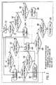
- FIG. 3is a flowchart illustrating the operation of the dual function keys of the embodiment of FIG. 2 for appropriate routing of the audio path;
- FIG. 4is a schematic view of a second embodiment of the invention, with a separate audio path toggle control
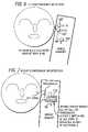
- FIGS. 5 to 8are diagrams of various automatic means for detecting use of a handset or headset, incorporated in further embodiments of the invention.
- the inventionconsists of a dual function to the controls on the handset and/or headset that control call answering and initiation, or a dedicated audio path control on the handset and/or headset, or an automatic means of detection of the audio path in use, whereby the audio path for the call is routed to the appropriate path, or is transferred to the most suitable path at the user's operation of the control.
- the correct pathis either automatically chosen, or can be chosen by the user in a simple and quick manner. For example:
- Button switch 36 in key pad 10is coupled by a software control function indicated schematically at 50 to a switch 52 in the first audio path 18 .
- Switch 52is also indicated schematically; it will in practice be implemented as a transistor switch or switches within processing section 8 .
- a further button switch 54is provided in headset 28 and is coupled via a line 56 through connectors 22 , 24 to processing section 8 .
- This line 56is coupled via a software function, indicated schematically as at 58 , to control a switch 60 in the second audio path.
- switch 60may be implemented as a transistor switch or switches in processing section 8 .
- switch 36when the mobile station indicates by ringing an incoming call, or when a user wishes to initiate a call, the user has the choice of operating switch 36 or switch 54 . Which switch is operated will depend on the user's convenience. Clearly if the headset is not connected, then the handset switch 36 will be operated. Alternatively, if the headset is connected and in position for use, then headset switch 54 may be operated. If switch 36 is operated, the audio path 18 is completed to loudspeaker 14 and microphone 16 by closure of switch 52 . If the headset switch 54 is operated, then the second audio path 20 to headset 28 is closed by closure of switch 60 .
- thisis a flowchart of a software routine that is stored in digital processing section 8 and that is responsive to the condition of switches 36 and 54 to close the appropriate audio path.
- an incoming callis monitored as at 72 . If there is an incoming call and the handset button 36 is pressed, 74 , then switch 52 is closed to route the audio on path 18 to the handset speaker and microphone 14 , 16 , as at 76 .
- the handset buttoncontinues to be monitored, 78 , and if depressed again, 80 , the call is terminated or a call hold function is implemented, depending on the preconfiguring of the handset.
- the handset buttonis not pressed, a check is then made on the headset button 54 as at 82 , 84 . If button 54 is pressed then the audio is routed by closure of switch 60 on second audio path 20 to the headset, 85 . Monitoring of the switches 36 , 54 continues to take place, 86 , 88 and if the handset button 36 is found to be depressed, then the audio is routed back to the first audio path, 76 . If the headset button 54 is depressed, then the call is terminated, 90 .
- the handset button switch 36is nevertheless monitored, 92 , and if found to be pressed, a call is originated or initiated, 94 , and the first audio path to the handset is enabled, 76 . If the handset button 36 is not depressed but monitoring of the headset button switch 54 shows it to be depressed, 96 , then a call is originated or initiated, 98 , and the second audio path 20 is enabled, 86 . If the headset button 54 is not depressed then the software returns to idle state 70 .
- the software function shown in FIG. 3 for call initiation and answeringcan be put under user control (instead of following the sequence as above) using, for example, short and long button presses, or double click action.
- a button switch 140is provided in key pad 10 , and this is coupled by a software control routine indicated schematically at 142 to switches 52 and 60 in the first and second audio paths 18 , 20 .
- a callis initiated or accepted by closure of switch 36 , and the audio can be switched or toggled between the first and second audio paths at any time by actuation of toggle switch 140 .
- FIGS. 5 to 8operate by an automatic sensing of the use of the handset or headset.
- the sensorsare shown schematically in FIG. 2 as S and T.
- Switch Sis coupled to software link 50 for operation of switch 52 in first audio path 18 .
- Switch Tis linked by line 56 to software link 58 , in order to operate switch 60 in second audio path 20 .
- closure of automatic switch S or automatic switch Twill have the effect of automatically enabling the respective first or second audio path 18 , 20 .
- sensor switch Sis implemented as a pair of sensor electrodes 150 in the mobile handset 2 connected to a capacitance measuring circuit 152 and thence to a threshold circuit 154 .
- a signalis provided by threshold circuit 154 to close switch 52 , via software link 50 .
- an infrared transmitter 160provides an infrared beam which is reflected during use of the handset by head to an infrared receiver 162 .
- the infrared receiveris coupled to a threshold circuit 164 which provides a switch closure signal for switch 52 in audio path 18 .
- an audio transducer 170is provided in the handset.
- a driving circuit 172provides an electric signal to the transducer 170 , and also detects the electrical impedance of the transducer. When the ear is held close to the transducer, the sound waves generated by the transducer will be channelled into the ear canal, and the apparent impedance of the transducer will change. This change is detected by driving circuit 172 and employed to switch 52 in first audio path 18 .
- a headsetcomprising a pair of headphones 180 with a headset band 182 .
- a switch 184is provided on the headset band 182 .
- the switchmay be of any type reacting to mechanical stress, for example, piezoelectric or magnetostrictive. Closure of the switch causes closure of switch 60 in second audio path 20 .
Landscapes
- Engineering & Computer Science (AREA)
- Signal Processing (AREA)
- Health & Medical Sciences (AREA)
- Otolaryngology (AREA)
- Telephone Function (AREA)
- Mobile Radio Communication Systems (AREA)
- Telephone Set Structure (AREA)
Abstract
Description
- With headset connected (whether via a cord or cordlessly, wire or wirelessly), if incoming call answered or initiated using call control (typically a switch button) on the headset, audio automatically routed to headset.
- With headset connected, if incoming call answered on handset, then audio automatically routed to handset. In case of call initiated on handset, optional set default routing to headset or handset.
- With headset connected, if incoming call answered or initiated on handset, and following that the control on the headset is activated, audio transfers from the handset to the headset.
- With headset connected, if incoming call answered or initiated on the headset, and following that the control on the handset is activated, audio transfers from the headset to the handset.
- Further control operation transfers the call as expected, or terminates the call if the control on the apparatus currently selected is operated again.
- Where no headset is connected, audio routes to handset.
- Simplified use of headset with mobile phone, avoiding user frustration.
- Enhanced human factor performance.
- Enhanced customer satisfaction.
Claims (15)
Applications Claiming Priority (2)
| Application Number | Priority Date | Filing Date | Title |
|---|---|---|---|
| EP00303977AEP1154621B1 (en) | 2000-05-11 | 2000-05-11 | Mobile station for telecommunications system |
| EP00303977.3 | 2000-05-11 |
Publications (2)
| Publication Number | Publication Date |
|---|---|
| US20020049079A1 US20020049079A1 (en) | 2002-04-25 |
| US7433715B2true US7433715B2 (en) | 2008-10-07 |
Family
ID=8172980
Family Applications (1)
| Application Number | Title | Priority Date | Filing Date |
|---|---|---|---|
| US09/854,256Expired - Fee RelatedUS7433715B2 (en) | 2000-05-11 | 2001-05-11 | Mobile station for telecommunications system |
Country Status (3)
| Country | Link |
|---|---|
| US (1) | US7433715B2 (en) |
| EP (1) | EP1154621B1 (en) |
| DE (1) | DE60037878T2 (en) |
Cited By (10)
| Publication number | Priority date | Publication date | Assignee | Title |
|---|---|---|---|---|
| US20050179056A1 (en)* | 2004-02-18 | 2005-08-18 | Teggatz Ross E. | System for resonant circuit tuning |
| US20070025561A1 (en)* | 2005-07-28 | 2007-02-01 | Gauger Daniel M Jr | Electronic interfacing with a head-mounted device |
| US20070093279A1 (en)* | 2005-10-12 | 2007-04-26 | Craig Janik | Wireless headset system for the automobile |
| US20070225035A1 (en)* | 2006-03-27 | 2007-09-27 | Gauger Daniel M Jr | Headset audio accessory |
| US20070281744A1 (en)* | 2006-06-02 | 2007-12-06 | Sony Ericsson Mobile Communications Ab | Audio output device selection for a portable electronic device |
| US20080167092A1 (en)* | 2007-01-04 | 2008-07-10 | Joji Ueda | Microphone techniques |
| US20100173672A1 (en)* | 2009-01-06 | 2010-07-08 | Larry Kuhl | Automatic audio routing dependent on dock state |
| US20110081862A1 (en)* | 2005-07-27 | 2011-04-07 | Denso Corporation | Handsfree device |
| US20130149990A1 (en)* | 2011-12-07 | 2013-06-13 | Kevin Otto | Wireless Communication Apparatus for Emergency Situations |
| US20130189963A1 (en)* | 2011-04-27 | 2013-07-25 | Research In Motion Limited | System and Method for Automatically Answering a Call on a Communication Device |
Families Citing this family (20)
| Publication number | Priority date | Publication date | Assignee | Title |
|---|---|---|---|---|
| DE60037878T2 (en) | 2000-05-11 | 2009-01-22 | Lucent Technologies Inc. | Mobile station for telecommunication system |
| JP2002237873A (en)* | 2001-02-09 | 2002-08-23 | Sony Corp | Portable radio terminal, sound sending-out method and sound taking-in method |
| EP1326410A1 (en)* | 2002-01-08 | 2003-07-09 | CCM Europe | Handsfree wireless communication system for handsfree communication between a user and a mobile phone |
| US7027841B2 (en) | 2002-02-11 | 2006-04-11 | Sharp Laboratories Of America, Inc. | Call operation method for a communication device |
| US7373182B2 (en)* | 2002-03-01 | 2008-05-13 | Varia Mobil Llc | Wireless mobile phone including a headset |
| JP4125036B2 (en)* | 2002-04-24 | 2008-07-23 | 松下電器産業株式会社 | Mobile terminal device |
| US6873884B2 (en)* | 2002-11-26 | 2005-03-29 | Ge Medical Systems Information Technology | Computer-equipped mobility device and method of connecting to a network |
| JP4167533B2 (en)* | 2003-04-16 | 2008-10-15 | Necインフロンティア株式会社 | Call system |
| CN1848870A (en)* | 2005-04-05 | 2006-10-18 | 摩托罗拉公司 | Communication apparatus and method for automatic answering incoming call |
| US7577459B2 (en)* | 2005-05-11 | 2009-08-18 | Nokia Corporation | Establishing a communication link |
| JP2007067742A (en)* | 2005-08-30 | 2007-03-15 | Kyocera Corp | Mobile phone |
| CN101410900A (en)* | 2006-03-24 | 2009-04-15 | 皇家飞利浦电子股份有限公司 | Device for and method of processing data for a wearable apparatus |
| CN101461218A (en)* | 2006-06-02 | 2009-06-17 | 索尼爱立信移动通讯股份有限公司 | Sound output selection for accessories |
| US9055413B2 (en)* | 2006-11-06 | 2015-06-09 | Plantronics, Inc. | Presence over existing cellular and land-line telephone networks |
| US9591392B2 (en)* | 2006-11-06 | 2017-03-07 | Plantronics, Inc. | Headset-derived real-time presence and communication systems and methods |
| CN101640720A (en)* | 2008-07-31 | 2010-02-03 | 鸿富锦精密工业(深圳)有限公司 | Mobile communication terminal and switching method of answer mode thereof |
| KR101694420B1 (en)* | 2009-09-03 | 2017-01-09 | 삼성전자주식회사 | Apparatus and method for improving of communication quality in a mobile terminal |
| US8706162B1 (en)* | 2013-03-05 | 2014-04-22 | Sony Corporation | Automatic routing of call audio at incoming call |
| KR20150033472A (en)* | 2013-09-24 | 2015-04-01 | 삼성전자주식회사 | Method for sharing status information and an electronic device thereof |
| CN110602312B (en) | 2019-08-21 | 2021-05-11 | 华为技术有限公司 | Call method, electronic device, and computer-readable storage medium |
Citations (15)
| Publication number | Priority date | Publication date | Assignee | Title |
|---|---|---|---|---|
| US4558178A (en)* | 1983-06-27 | 1985-12-10 | Tokyo Shibaura Denki Kabushiki Kaisha | Wireless telephone apparatus including both a telephone handset and a telephone headset |
| US5191602A (en) | 1991-01-09 | 1993-03-02 | Plantronics, Inc. | Cellular telephone headset |
| US5224151A (en)* | 1992-04-01 | 1993-06-29 | At&T Bell Laboratories | Automatic handset-speakephone switching arrangement for portable communication device |
| US5227667A (en)* | 1989-01-10 | 1993-07-13 | Omron Corporation | Microwave proximity switch |
| US5504812A (en) | 1994-10-11 | 1996-04-02 | Motorola, Inc. | Headset for use with a radiotelephone |
| US5554973A (en)* | 1994-06-08 | 1996-09-10 | Seikosha Co., Ltd. | Electrostatic capacitance-type sensor |
| US5729604A (en)* | 1996-03-14 | 1998-03-17 | Northern Telecom Limited | Safety switch for communication device |
| EP0840465A2 (en) | 1996-10-31 | 1998-05-06 | Nokia Mobile Phones Ltd. | User interface for mobile telephone |
| EP0912031A2 (en) | 1997-10-24 | 1999-04-28 | Nortel Networks Corporation | Light guide implementation of a proximity detector |
| US6038457A (en)* | 1997-12-05 | 2000-03-14 | Motorola, Inc. | Apparatus and method for detecting and powering an accessory |
| US6115620A (en)* | 1998-05-20 | 2000-09-05 | Motorola, Inc. | Mode-switchable portable communication device and method therefor |
| US6301491B1 (en)* | 1998-06-12 | 2001-10-09 | Samsung Electronics Co., Ltd. | Device and method for radio terminal with hands-free function |
| EP1154621A1 (en) | 2000-05-11 | 2001-11-14 | Lucent Technologies Inc. | Mobile station for telecommunications system |
| US6397087B1 (en)* | 1998-11-07 | 2002-05-28 | Samsung Electronics, Co., Ltd. | Device for controlling the connection of a built-in type ear-microphone for portable radio terminal |
| US6434407B1 (en)* | 1999-12-03 | 2002-08-13 | Denso Corporation, Ltd. | Speakerphone feature for a wireless handset |
- 2000
- 2000-05-11DEDE60037878Tpatent/DE60037878T2/ennot_activeExpired - Lifetime
- 2000-05-11EPEP00303977Apatent/EP1154621B1/ennot_activeExpired - Lifetime
- 2001
- 2001-05-11USUS09/854,256patent/US7433715B2/ennot_activeExpired - Fee Related
Patent Citations (15)
| Publication number | Priority date | Publication date | Assignee | Title |
|---|---|---|---|---|
| US4558178A (en)* | 1983-06-27 | 1985-12-10 | Tokyo Shibaura Denki Kabushiki Kaisha | Wireless telephone apparatus including both a telephone handset and a telephone headset |
| US5227667A (en)* | 1989-01-10 | 1993-07-13 | Omron Corporation | Microwave proximity switch |
| US5191602A (en) | 1991-01-09 | 1993-03-02 | Plantronics, Inc. | Cellular telephone headset |
| US5224151A (en)* | 1992-04-01 | 1993-06-29 | At&T Bell Laboratories | Automatic handset-speakephone switching arrangement for portable communication device |
| US5554973A (en)* | 1994-06-08 | 1996-09-10 | Seikosha Co., Ltd. | Electrostatic capacitance-type sensor |
| US5504812A (en) | 1994-10-11 | 1996-04-02 | Motorola, Inc. | Headset for use with a radiotelephone |
| US5729604A (en)* | 1996-03-14 | 1998-03-17 | Northern Telecom Limited | Safety switch for communication device |
| EP0840465A2 (en) | 1996-10-31 | 1998-05-06 | Nokia Mobile Phones Ltd. | User interface for mobile telephone |
| EP0912031A2 (en) | 1997-10-24 | 1999-04-28 | Nortel Networks Corporation | Light guide implementation of a proximity detector |
| US6038457A (en)* | 1997-12-05 | 2000-03-14 | Motorola, Inc. | Apparatus and method for detecting and powering an accessory |
| US6115620A (en)* | 1998-05-20 | 2000-09-05 | Motorola, Inc. | Mode-switchable portable communication device and method therefor |
| US6301491B1 (en)* | 1998-06-12 | 2001-10-09 | Samsung Electronics Co., Ltd. | Device and method for radio terminal with hands-free function |
| US6397087B1 (en)* | 1998-11-07 | 2002-05-28 | Samsung Electronics, Co., Ltd. | Device for controlling the connection of a built-in type ear-microphone for portable radio terminal |
| US6434407B1 (en)* | 1999-12-03 | 2002-08-13 | Denso Corporation, Ltd. | Speakerphone feature for a wireless handset |
| EP1154621A1 (en) | 2000-05-11 | 2001-11-14 | Lucent Technologies Inc. | Mobile station for telecommunications system |
Cited By (20)
| Publication number | Priority date | Publication date | Assignee | Title |
|---|---|---|---|---|
| US20050179056A1 (en)* | 2004-02-18 | 2005-08-18 | Teggatz Ross E. | System for resonant circuit tuning |
| US8311589B2 (en)* | 2005-07-27 | 2012-11-13 | Denso Corporation | Handsfree device |
| US20110081862A1 (en)* | 2005-07-27 | 2011-04-07 | Denso Corporation | Handsfree device |
| US20070025561A1 (en)* | 2005-07-28 | 2007-02-01 | Gauger Daniel M Jr | Electronic interfacing with a head-mounted device |
| US8031878B2 (en) | 2005-07-28 | 2011-10-04 | Bose Corporation | Electronic interfacing with a head-mounted device |
| US20110059697A1 (en)* | 2005-10-12 | 2011-03-10 | Craig Janik | Wireless headset system for the automobile |
| US8099141B2 (en)* | 2005-10-12 | 2012-01-17 | Maverick Lifestyle Corporation | Wireless headset system for the automobile |
| US20070093279A1 (en)* | 2005-10-12 | 2007-04-26 | Craig Janik | Wireless headset system for the automobile |
| US7627352B2 (en)* | 2006-03-27 | 2009-12-01 | Gauger Jr Daniel M | Headset audio accessory |
| US20070225035A1 (en)* | 2006-03-27 | 2007-09-27 | Gauger Daniel M Jr | Headset audio accessory |
| US7930007B2 (en)* | 2006-06-02 | 2011-04-19 | Sony Ericsson Mobile Communications Ab | Audio output device selection for a portable electronic device |
| US20070281744A1 (en)* | 2006-06-02 | 2007-12-06 | Sony Ericsson Mobile Communications Ab | Audio output device selection for a portable electronic device |
| US20110159925A1 (en)* | 2006-06-02 | 2011-06-30 | Sony Ericsson Mobile Communications Ab | Audio output device selection for a portable electronic device |
| US7920903B2 (en) | 2007-01-04 | 2011-04-05 | Bose Corporation | Microphone techniques |
| US20080167092A1 (en)* | 2007-01-04 | 2008-07-10 | Joji Ueda | Microphone techniques |
| US20100173672A1 (en)* | 2009-01-06 | 2010-07-08 | Larry Kuhl | Automatic audio routing dependent on dock state |
| US8583176B2 (en) | 2009-01-06 | 2013-11-12 | Blackberry Limited | Automatic audio routing dependent on dock state |
| US20130189963A1 (en)* | 2011-04-27 | 2013-07-25 | Research In Motion Limited | System and Method for Automatically Answering a Call on a Communication Device |
| US8897757B2 (en)* | 2011-04-27 | 2014-11-25 | Blackberry Limited | System and method for automatically answering a call on a communication device |
| US20130149990A1 (en)* | 2011-12-07 | 2013-06-13 | Kevin Otto | Wireless Communication Apparatus for Emergency Situations |
Also Published As
| Publication number | Publication date |
|---|---|
| DE60037878T2 (en) | 2009-01-22 |
| EP1154621A1 (en) | 2001-11-14 |
| EP1154621B1 (en) | 2008-01-23 |
| US20020049079A1 (en) | 2002-04-25 |
| DE60037878D1 (en) | 2008-03-13 |
Similar Documents
| Publication | Publication Date | Title |
|---|---|---|
| US7433715B2 (en) | Mobile station for telecommunications system | |
| US6002763A (en) | Telephone with a mute ringer function having an automatic ringer reactivation capability | |
| US7567656B2 (en) | Telephone communication apparatus | |
| US20030099367A1 (en) | Portable radio terminal, and sound delivery method and sound intake method | |
| US7702368B2 (en) | Apparatus and method for controlling speaker volume of push-to-talk (PTT) phone | |
| JPH0273751A (en) | Cordless telephone set | |
| EP1531606A1 (en) | Collapsible mobile telephone | |
| JPH11163989A (en) | Portable telephone set | |
| JPH03198436A (en) | wireless telephone equipment | |
| US7551600B2 (en) | Telephone terminal, call system, internet terminal and terminal control program | |
| KR200261461Y1 (en) | hands free for music player | |
| KR100621749B1 (en) | Mobile communication terminal and method of changing incoming call notification mode of mobile communication terminal using the same | |
| JPH11163987A (en) | Telephone | |
| KR200356181Y1 (en) | Compatible multi-functional earphone device for portable handheld radiotelephone and audio apparatus | |
| KR100450139B1 (en) | Ear-mike having the receiving and sending buttons and mobile communication terminal using the same | |
| JPH04354234A (en) | Telephone set | |
| KR200259991Y1 (en) | Charger of mobile phone comprising adaptor for connecting a mobile phone and a telephonic handset | |
| JP3704456B2 (en) | Telephone | |
| JP3024412B2 (en) | Handset | |
| KR200299965Y1 (en) | Device for connecting the Ear Set to Telephone | |
| JPH09252341A (en) | Telephone set | |
| JPH03212045A (en) | Cordless telephone system | |
| JPH11239199A (en) | Telephone | |
| KR200205580Y1 (en) | Apparatus for headset type terminal comprising audio output function in communication system | |
| KR100450140B1 (en) | Ear-mike having memory button and mobile communication terminal using the same |
Legal Events
| Date | Code | Title | Description |
|---|---|---|---|
| AS | Assignment | Owner name:AGERE SYSTEMS GUARDIAN CORP., FLORIDA Free format text:ASSIGNMENT OF ASSIGNORS INTEREST;ASSIGNORS:BUCKLEY, ROBERT ANTHONY;REDSHAW, NIC ANDREW;VERNEY, RICHARD PETER;REEL/FRAME:012456/0934 Effective date:20011113 | |
| STCF | Information on status: patent grant | Free format text:PATENTED CASE | |
| FEPP | Fee payment procedure | Free format text:PAYER NUMBER DE-ASSIGNED (ORIGINAL EVENT CODE: RMPN); ENTITY STATUS OF PATENT OWNER: LARGE ENTITY Free format text:PAYOR NUMBER ASSIGNED (ORIGINAL EVENT CODE: ASPN); ENTITY STATUS OF PATENT OWNER: LARGE ENTITY | |
| FPAY | Fee payment | Year of fee payment:4 | |
| AS | Assignment | Owner name:DEUTSCHE BANK AG NEW YORK BRANCH, AS COLLATERAL AG Free format text:PATENT SECURITY AGREEMENT;ASSIGNORS:LSI CORPORATION;AGERE SYSTEMS LLC;REEL/FRAME:032856/0031 Effective date:20140506 | |
| AS | Assignment | Owner name:AVAGO TECHNOLOGIES GENERAL IP (SINGAPORE) PTE. LTD Free format text:ASSIGNMENT OF ASSIGNORS INTEREST;ASSIGNOR:AGERE SYSTEMS LLC;REEL/FRAME:035365/0634 Effective date:20140804 | |
| AS | Assignment | Owner name:LSI CORPORATION, CALIFORNIA Free format text:TERMINATION AND RELEASE OF SECURITY INTEREST IN PATENT RIGHTS (RELEASES RF 032856-0031);ASSIGNOR:DEUTSCHE BANK AG NEW YORK BRANCH, AS COLLATERAL AGENT;REEL/FRAME:037684/0039 Effective date:20160201 Owner name:AGERE SYSTEMS LLC, PENNSYLVANIA Free format text:TERMINATION AND RELEASE OF SECURITY INTEREST IN PATENT RIGHTS (RELEASES RF 032856-0031);ASSIGNOR:DEUTSCHE BANK AG NEW YORK BRANCH, AS COLLATERAL AGENT;REEL/FRAME:037684/0039 Effective date:20160201 | |
| AS | Assignment | Owner name:BANK OF AMERICA, N.A., AS COLLATERAL AGENT, NORTH CAROLINA Free format text:PATENT SECURITY AGREEMENT;ASSIGNOR:AVAGO TECHNOLOGIES GENERAL IP (SINGAPORE) PTE. LTD.;REEL/FRAME:037808/0001 Effective date:20160201 Owner name:BANK OF AMERICA, N.A., AS COLLATERAL AGENT, NORTH Free format text:PATENT SECURITY AGREEMENT;ASSIGNOR:AVAGO TECHNOLOGIES GENERAL IP (SINGAPORE) PTE. LTD.;REEL/FRAME:037808/0001 Effective date:20160201 | |
| FPAY | Fee payment | Year of fee payment:8 | |
| AS | Assignment | Owner name:AVAGO TECHNOLOGIES GENERAL IP (SINGAPORE) PTE. LTD., SINGAPORE Free format text:TERMINATION AND RELEASE OF SECURITY INTEREST IN PATENTS;ASSIGNOR:BANK OF AMERICA, N.A., AS COLLATERAL AGENT;REEL/FRAME:041710/0001 Effective date:20170119 Owner name:AVAGO TECHNOLOGIES GENERAL IP (SINGAPORE) PTE. LTD Free format text:TERMINATION AND RELEASE OF SECURITY INTEREST IN PATENTS;ASSIGNOR:BANK OF AMERICA, N.A., AS COLLATERAL AGENT;REEL/FRAME:041710/0001 Effective date:20170119 | |
| AS | Assignment | Owner name:AVAGO TECHNOLOGIES INTERNATIONAL SALES PTE. LIMITE Free format text:MERGER;ASSIGNOR:AVAGO TECHNOLOGIES GENERAL IP (SINGAPORE) PTE. LTD.;REEL/FRAME:047195/0658 Effective date:20180509 | |
| AS | Assignment | Owner name:AVAGO TECHNOLOGIES INTERNATIONAL SALES PTE. LIMITE Free format text:CORRECTIVE ASSIGNMENT TO CORRECT THE EFFECTIVE DATE OF MERGER PREVIOUSLY RECORDED ON REEL 047195 FRAME 0658. ASSIGNOR(S) HEREBY CONFIRMS THE THE EFFECTIVE DATE IS 09/05/2018;ASSIGNOR:AVAGO TECHNOLOGIES GENERAL IP (SINGAPORE) PTE. LTD.;REEL/FRAME:047357/0302 Effective date:20180905 | |
| AS | Assignment | Owner name:AVAGO TECHNOLOGIES INTERNATIONAL SALES PTE. LIMITE Free format text:CORRECTIVE ASSIGNMENT TO CORRECT THE ERROR IN RECORDING THE MERGER PREVIOUSLY RECORDED AT REEL: 047357 FRAME: 0302. ASSIGNOR(S) HEREBY CONFIRMS THE ASSIGNMENT;ASSIGNOR:AVAGO TECHNOLOGIES GENERAL IP (SINGAPORE) PTE. LTD.;REEL/FRAME:048674/0834 Effective date:20180905 | |
| FEPP | Fee payment procedure | Free format text:MAINTENANCE FEE REMINDER MAILED (ORIGINAL EVENT CODE: REM.); ENTITY STATUS OF PATENT OWNER: LARGE ENTITY | |
| LAPS | Lapse for failure to pay maintenance fees | Free format text:PATENT EXPIRED FOR FAILURE TO PAY MAINTENANCE FEES (ORIGINAL EVENT CODE: EXP.); ENTITY STATUS OF PATENT OWNER: LARGE ENTITY | |
| STCH | Information on status: patent discontinuation | Free format text:PATENT EXPIRED DUE TO NONPAYMENT OF MAINTENANCE FEES UNDER 37 CFR 1.362 | |
| FP | Lapsed due to failure to pay maintenance fee | Effective date:20201007 |