US7433704B2 - Portable communication terminal - Google Patents
Portable communication terminalDownload PDFInfo
- Publication number
- US7433704B2 US7433704B2US11/058,273US5827305AUS7433704B2US 7433704 B2US7433704 B2US 7433704B2US 5827305 AUS5827305 AUS 5827305AUS 7433704 B2US7433704 B2US 7433704B2
- Authority
- US
- United States
- Prior art keywords
- acoustic
- input
- output
- unit
- processing unit
- Prior art date
- Legal status (The legal status is an assumption and is not a legal conclusion. Google has not performed a legal analysis and makes no representation as to the accuracy of the status listed.)
- Expired - Fee Related, expires
Links
- 230000006854communicationEffects0.000titleclaimsabstractdescription78
- 238000004891communicationMethods0.000titleclaimsabstractdescription64
- 238000012545processingMethods0.000claimsabstractdescription64
- JGKXEMYIHDYWCZ-JFUSQASVSA-N(2r)-2-[(r)-[[(6r)-6-amino-6-carboxyhexanoyl]amino]-carboxymethyl]-5-methylidene-2h-1,3-thiazine-4-carboxylic acidChemical compoundOC(=O)[C@H](N)CCCCC(=O)N[C@H](C(O)=O)[C@H]1SCC(=C)C(C(O)=O)=N1JGKXEMYIHDYWCZ-JFUSQASVSA-N0.000description39
- 238000000034methodMethods0.000description20
- 238000010586diagramMethods0.000description6
- 238000007796conventional methodMethods0.000description2
- 238000013461designMethods0.000description1
- 230000000694effectsEffects0.000description1
- 230000002349favourable effectEffects0.000description1
- 239000010445micaSubstances0.000description1
- 229910052618mica groupInorganic materials0.000description1
Images


Classifications
- H—ELECTRICITY
- H04—ELECTRIC COMMUNICATION TECHNIQUE
- H04M—TELEPHONIC COMMUNICATION
- H04M1/00—Substation equipment, e.g. for use by subscribers
- H04M1/60—Substation equipment, e.g. for use by subscribers including speech amplifiers
- H04M1/6033—Substation equipment, e.g. for use by subscribers including speech amplifiers for providing handsfree use or a loudspeaker mode in telephone sets
- H04M1/6041—Portable telephones adapted for handsfree use
- H04M1/605—Portable telephones adapted for handsfree use involving control of the receiver volume to provide a dual operational mode at close or far distance from the user
- H—ELECTRICITY
- H04—ELECTRIC COMMUNICATION TECHNIQUE
- H04M—TELEPHONIC COMMUNICATION
- H04M1/00—Substation equipment, e.g. for use by subscribers
- H04M1/02—Constructional features of telephone sets
- H04M1/0202—Portable telephone sets, e.g. cordless phones, mobile phones or bar type handsets
- H04M1/0206—Portable telephones comprising a plurality of mechanically joined movable body parts, e.g. hinged housings
- H04M1/0208—Portable telephones comprising a plurality of mechanically joined movable body parts, e.g. hinged housings characterized by the relative motions of the body parts
- H04M1/0214—Foldable telephones, i.e. with body parts pivoting to an open position around an axis parallel to the plane they define in closed position
- H—ELECTRICITY
- H04—ELECTRIC COMMUNICATION TECHNIQUE
- H04M—TELEPHONIC COMMUNICATION
- H04M1/00—Substation equipment, e.g. for use by subscribers
- H04M1/02—Constructional features of telephone sets
- H04M1/0202—Portable telephone sets, e.g. cordless phones, mobile phones or bar type handsets
- H04M1/0206—Portable telephones comprising a plurality of mechanically joined movable body parts, e.g. hinged housings
- H04M1/0208—Portable telephones comprising a plurality of mechanically joined movable body parts, e.g. hinged housings characterized by the relative motions of the body parts
- H04M1/0225—Rotatable telephones, i.e. the body parts pivoting to an open position around an axis perpendicular to the plane they define in closed position
- H—ELECTRICITY
- H04—ELECTRIC COMMUNICATION TECHNIQUE
- H04M—TELEPHONIC COMMUNICATION
- H04M1/00—Substation equipment, e.g. for use by subscribers
- H04M1/02—Constructional features of telephone sets
- H04M1/0202—Portable telephone sets, e.g. cordless phones, mobile phones or bar type handsets
- H04M1/0206—Portable telephones comprising a plurality of mechanically joined movable body parts, e.g. hinged housings
- H04M1/0241—Portable telephones comprising a plurality of mechanically joined movable body parts, e.g. hinged housings using relative motion of the body parts to change the operational status of the telephone set, e.g. switching on/off, answering incoming call
- H04M1/0245—Portable telephones comprising a plurality of mechanically joined movable body parts, e.g. hinged housings using relative motion of the body parts to change the operational status of the telephone set, e.g. switching on/off, answering incoming call using open/close detection
- H—ELECTRICITY
- H04—ELECTRIC COMMUNICATION TECHNIQUE
- H04M—TELEPHONIC COMMUNICATION
- H04M1/00—Substation equipment, e.g. for use by subscribers
- H04M1/72—Mobile telephones; Cordless telephones, i.e. devices for establishing wireless links to base stations without route selection
- H04M1/724—User interfaces specially adapted for cordless or mobile telephones
- H04M1/72403—User interfaces specially adapted for cordless or mobile telephones with means for local support of applications that increase the functionality
- H04M1/72442—User interfaces specially adapted for cordless or mobile telephones with means for local support of applications that increase the functionality for playing music files
Definitions
- the present inventionrelates to a portable communication terminal such as a portable telephone or a schedule management terminal.
- the present inventionrelates to a portable communication terminal having a plurality of acoustic input-output devices.
- portable telephones having a plurality of communication functionssuch as dynamic image recording, reproducing, transmitting and receiving functions, or the so-called TV telephone function which makes it possible to talk while reproducing a dynamic image, besides a typical talking function are spread.
- the use form of the userdiffers according to the communication function. For example, the terminal is brought into contact with an ear at the time of ordinary talk, whereas the user faces the terminal at the time of use of video phone.
- An object of the present inventionis to provide portable communication terminals capable of smoothly executing acoustic processing respectively suitable for various communication functions.
- a portable communication terminalincludes an acoustic input-output unit including a plurality of acoustic input means to conduct acoustic inputting and acoustic output means to conduct acoustic outputting, a communication processing unit which selectively executes mutually different communication processes using at least one of the means included in the acoustic input-output unit, and an acoustic processing unit which determines an order of operation of the acoustic input-output unit to be conducted by the means according to a communication process executed by the communication processing unit and gives the determined operation order to the acoustic input-output unit.
- Another portable communication terminalincludes an acoustic input-output unit including acoustic input means to conduct acoustic inputting and a plurality of acoustic output means to conduct acoustic outputting, a communication processing unit which selectively executes mutually different communication processes using at least one of the means included in the acoustic input-output unit, and an acoustic processing unit which determines an order of operation of the acoustic input-output unit to be conducted by the means according to a communication process executed by the communication processing unit, and gives the determined operation order to the acoustic input-output unit.
- the acoustic input and output devicesare controlled in operation based on communication processing executed in the terminal. Therefore, an acoustic system suitable for the communication processing can be provided.
- FIG. 1is a block diagram showing a configuration of a portable telephone in first and second embodiments according to the present invention
- FIGS. 2A and 2Bare exterior views of a portable telephone in first and second embodiments
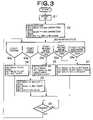
- FIG. 3is a flow chart showing an operation procedure in a first embodiment
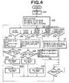
- FIG. 4is a flow chart showing an operation procedure in a second embodiment
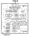
- FIG. 5is a block diagram showing a configuration of a portable telephone in a third embodiment according to the present invention.
- FIGS. 6A and 6Bare exterior views of a portable telephone in a third embodiment
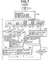
- FIG. 7is a flow chart showing an operation procedure in a third embodiment
- FIG. 8is a block diagram showing a configuration of a portable telephone in fourth and fifth embodiments according to the present invention.
- FIG. 9is an exterior view of a portable telephone in a fourth embodiment.
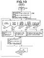
- FIG. 10is a flow chart showing an operation procedure in a fourth embodiment
- FIGS. 11A and 11Bare exterior views of a portable telephone in a fifth embodiment.
- FIG. 12is a flow chart showing an operation procedure in a fifth embodiment.
- FIG. 1is a block diagram showing a configuration of an embodiment of a portable communication terminal according to the present invention.
- a portable telephone 101which is a portable communication terminal in the embodiment includes an acoustic input-output unit 10 having a plurality of acoustic input means and a plurality of acoustic output means, a communication processing unit 20 which selectively executes communication processing such as ordinary talking using only voice, talking using video phone, dynamic image recording and reproduction, and voice-music reproduction, and an acoustic processing unit 50 which gives an operation order to the acoustic input-output unit 10 according to communication processing in the communication processing unit 20 .
- the acoustic input-output unit 10includes an SPK 11 , which is a speaker, and a SPK drive unit 12 serving as acoustic output means, a REC 13 , which is a receiver fulfilling a talking receiver function, and a REC drive unit 14 serving as the acoustic output means in the same way, microphones MIC 15 a and MIC 15 b each serving as acoustic input means, input-output switches 16 a and 16 b which conduct input-output switching described later on the MIC 15 a and MIC 15 b , and an MIC input detecting unit 17 which detects sounds input via the MIC 15 a and MIC 15 b.
- SPK 11which is a speaker
- SPK drive unit 12serving as acoustic output means
- a REC 13which is a receiver fulfilling a talking receiver function
- a REC drive unit 14serving as the acoustic output means in the same way
- the communication processing unit 20includes a transmitting and receiving ANT (antenna) 21 which transmits and receives a radio signal of the portable telephone 101 , a portable telephone radio unit 22 which conducts modulation and demodulation of a radio signal, a system processing unit 23 which conducts portable telephone signal processing, a CPU 24 , keys 25 serving as an operation input unit, a key detecting unit 26 which detects input conducted by using the keys 25 , an LCD 27 and an LCD driving unit 28 which fulfill a display function, a ROM 29 which stores a program, and a RAM 30 which stores data.
- ANTantigenna
- the MIC 15 a and MIC 15 b in the present embodimentfulfill the function of serving as the acoustic output means such as the SPK 11 , besides the function of serving as the acoustic input means.
- the MIC 15 A and MIC 15 Bare made to operate as microphones or speakers according to the communication processing such as talking or image recording.
- This controlis implemented by the acoustic processing unit 50 giving an operation order to the SPK drive unit 12 and the MICA input detecting unit 17 , and the input-output switches 16 a and 16 b conducting acoustic signal connection switching.
- the MIC 15 a and the MIC 15 bwhich originally serve as the acoustic input means, function as the acoustic output means as well, additional disposition of speaker devices becomes unnecessary and effective use of the design space in the portable telephone 101 becomes possible.
- a dynamic microphonewhich is a kind of microphone can be used.
- the dynamic microphonehas a coil connected to an acoustic plate disposed in a magnetic field of a magnet. Vibration of the acoustic plate is transmitted to the coil to vary the magnetic field. As a result, a current of the input signal flows through the coil.
- FIGS. 2A and 2Bschematically show exterior views of the portable telephone 101 in the embodiment.
- the portable telephone 101is a folding telephone in which a casing upper part 101 a including the REC 13 and the LCD 27 is connected to a casing lower part 101 b including keys 25 by a hinge mechanism 101 c .
- the MIC 15 a and MIC 15 b described aboveare provided on the casing lower part 101 b .
- the SPK 11is provided on a surface of the casing upper part 101 a , i.e., a surface facing in opposite directions a face of the LCD 27 .
- the acoustic processing unit 50sets the MICs 16 a and 15 b to a microphone operation mode and the SPK 11 to a monaural speaker (left+right) operation mode in the SPK drive unit 12 , the MIC input detecting unit 17 , and the input-output switches 16 a and 16 b as initialization processing for the acoustic input-output unit 10 (step S 2 ).
- the REC 13is in a receiver operation mode.
- operation parameters for conducting acoustic inputtingare set in them.
- operation parameters for conducting voice output with a volume suitable for receiving operationin which the user brings the REC 13 into contact with an ear, are set.
- operation parameters for outputting voice with a volume suitable for the user facing the portable telephone 101 as in video phonesare set.
- a greater clearer voice output as compared with the above-described receiver operation modeis demanded. Accordingly, a greater output gain is set, and a low frequency band in frequency characteristics is set to become high.
- the CPU 24 in the communication processing unit 20monitors the operation state of the portable telephone 101 . According to the state, the CPU 24 specifies an operation mode of the acoustic input-output unit 10 to the acoustic processing unit 50 (step S 3 ).
- the CPU 24orders the acoustic processing unit 50 to bring one of the MIC 15 a and the MIC 15 b operate into the microphone operation mode and bring the other of the microphones and the SPK 11 into an OFF mode, i.e., stop their operation (step S 4 ).
- the MICs 15 a and 15 bare close to the mouth of the user so as to capture an uttered sound easily, and consequently one of the microphones is brought into operation whereas the other is stopped. As a result, power consumption can be suppressed.
- the MIC 15 aWhen starting talking on video phone (step S 3 b ), the MIC 15 a is made to operate in a stereo (left) microphone operation mode and the MIC 15 b is made to operate in a stereo (right) microphone operation mode, whereas the SPK 11 is made to operate in the speaker operation mode (step S 5 ).
- operation parameters for stereo acoustic inputare set with respect to the MICs 15 a and 15 b .
- step S 3 cWhen recording a moving image is started (step S 3 c ), the MIC 15 a is set to the stereo (left) microphone operation mode and the MIC 15 b is set to the stereo (right) microphone operation mode. Thereby, stereo acoustic inputting similar to that described above is conducted. Since the external acoustic outputting is unnecessary at the time of image recording, the SPK 11 is set to the OFF mode (step S 6 ).
- the MIC 15 ais set to the stereo (left) speaker operation mode and the MIC 15 b is set to the stereo (right) speaker operation mode whereas the SPK 11 is set to the monaural (left+right) speaker operation mode (step S 7 ).
- the MICs 15 a and 15 boperate as means that outputs the sound to the outside together with the SPK 11 instead of operating as the original acoustic input means.
- Operation switching of the MICs 15 a and 15 bis executed by switching the connection of the MICs 15 a and 15 b from the MIC input detecting unit 17 to the SPK drive unit 12 with the input-output switches 16 a and 16 b as described above.
- stereo acoustic outputting using the MICs 15 a and 15 bis executed besides the acoustic outputting using the SPK 11 .
- voice and musiccan be provided for the user with feeling of presence.
- the so-called multi-speaker systemcan be constructed by thus utilizing the MICs 15 a and 15 b.
- step S 8the CPU 24 returns to the step S 3 in order to monitor the state again.
- any one of the MICs 15 a and 15 bis set to the OFF mode (step S 4 ) at the time of ordinary talking (step S 3 a ).
- the microphone to be set to the OFF modemay be determined on the basis of a predetermined condition.
- step S 21the portable telephone 101 brings the MICs 15 a and 15 b into the OFF mode as shown in FIG. 4 (step S 22 ). Then, the MICs 15 a and 15 b is set to the microphone operation mode at the time of ordinary talking (step S 3 a ).
- the acoustic processing unit 50compares input levels of the MICs 15 a and 15 b detected by the MIC input detecting unit 17 with each other. If the input level of the MIC 15 a is higher than that of the MIC 15 b (yes at step S 24 ), the MIC 15 b is set to the OFF mode to stop its operation and the MIC 15 a is made to operate in the microphone operation mode (step S 25 ). If the input level of the MIC 15 a is lower than that of the MIC 15 b (no at the step S 24 ), the MIC 15 a is set to the OFF mode and the MIC 15 b is made to operate in the microphone operation mode (step S 26 ). At the time of video phone (step S 3 b ) as well, one of the microphones can be adapted to be stopped in the same way as the above-described procedure (steps S 27 to S 30 ).
- the power dissipation of the portable telephone 101can be suppressed and a microphone that implements a more favorable voice input can be automatically selected.
- FIG. 5is a block diagram showing a configuration of a portable telephone 103 in a third embodiment.
- the portable telephone 103is a folding terminal in the same way as the portable telephone 101 described with reference to FIG. 1 .
- the portable telephone 103includes a MIC 15 c which is a microphone serving as the acoustic input means, and an opening and closing detecting unit 31 which detects the open/close state of the casing.
- a pressure sensorprovided on the inside of folding near a hinge mechanism in a typical folding portable telephone can be used.
- FIGS. 6A and 6Bschematically show exterior views of the portable telephone 103 .
- the portable telephone 103includes the MIC 15 a , MIC 15 b and SPK 11 on a surface of a casing upper part 103 a , and a MIC 15 c on a face of a casing lower part 103 b coplanar with the keys 25 .
- FIG. 6Bshows the state in which the casing of the portable telephone 103 is closed, i.e., the casing upper part 103 a is laid on the face of the keys 25 in the casing upper part 103 a.
- step S 31the portable telephone 103 brings the MICs 15 a and 15 b into the OFF mode and sets the MIC 15 c to the MIC operation mode (step S 32 ).
- the CPU 24checks the opening and closing state of the casing of the portable telephone 103 by using the opening and closing detecting unit 31 . If as a result the casing is in the opened state, i.e., the casing is in the state shown in FIG. 6A (no at step S 33 ), the CPU 24 notifies the acoustic processing unit 50 to that effect.
- the acoustic processing unit 50sets the MICs 15 a and 15 b , which become unnecessary for talking in the state shown in FIG. 6A , and the SPK 11 to the OFF mode.
- the acoustic processing unit 50sets the MIC 15 c serving as transmitting means at the time of talking in the illustrated state to the MIC operation mode (step S 34 ).
- the acoustic processing unit 50makes the MICs 15 a and 15 b disposed on the surface of the casing upper part 103 a operate in the MIC operation mode as transmitting means and makes the SPK 11 operate in a receiver operation mode as receiving means in order to make talking possible in the illustrated state. And the acoustic processing unit 50 sets the MIC 15 c , which cannot be used in the illustrated state, to the OFF mode (step S 35 ).
- the MICs 15 a and 15 bare made to operate in the MIC operation mode and the SPK 11 is made to operate in the monaural (left+right) speaker operation mode, whereas the MIC 15 c is set to the OFF mode.
- the casing of the portable telephone 103is in the open state when it is used as video phone (no at the step S 36 )
- the MICs 15 a and 15 bare set to the OFF mode and the MIC 15 c is made to operate in the MIC operation mode whereas the SPK 11 is made to operate in the monaural (left+right) speaker operation mode.
- the portable telephone 103therefore, it is possible to provide an acoustic input-output function suitable for ordinary talking or talking using the video phone according to the opening and closing state of the casing.
- step S 3 cAt the time of each of moving image recording (step S 3 c ), moving image reproduction (step S 3 d ) and voice and music reproduction (step S 3 e ), the MIC 15 c is set to the OFF mode and setting similar to the steps S 6 and S 7 in the first embodiment shown in FIG. 3 is conducted (steps S 39 and S 40 ).
- FIG. 8is a block diagram showing a configuration of a portable telephone 104 in a fourth embodiment.
- the acoustic input-output unit 10 in the portable telephone 104includes the SPK 11 , REC 13 a and REC 13 b as the acoustic output means.
- the acoustic input-output unit 10further includes a signal source switch 18 a and a signal source switch 18 b for switching and setting the above-described receiver operation mode or speaker operation mode in the RECs 13 a and 13 b.
- the signal source switch 18 aconnects the REC 13 a to the REC drive unit 14 .
- the signal source switch 18 aconnects the REC 13 a to the SPK drive unit 12 .
- FIG. 9schematically shows an exterior view of the portable telephone 104 .
- the portable telephone 104is a portable telephone of rotary type having a casing upper part 104 a and a casing lower part 104 b coupled by a pivot mechanism 104 c .
- the REC 13 a and REC 13 bare disposed near an LCD 27 on the casing upper part 104 a
- an MIC 15is disposed near the keys 25 on the casing lower part 104 b
- the SPK 11is disposed on a tip face of the casing lower part 104 b.
- step S 41the portable telephone 104 sets the REC 13 a and REC 13 b to the receiver operation mode, and sets the SPK 11 to the monaural (left+right) speaker operation mode (step S 42 ).
- step S 3 athe user uses it while keeping it in contact with an ear, and consequently one of the REC 13 a and REC 13 b is made to operate in the receiver operation mode and the other of the receivers and the SPK 11 are turned off (step S 43 ).
- the REC 13 ais made to operate and the REC 13 b is turned off.
- the REC 13 ais made to operate in the stereo (left) speaker operation mode and the REC 13 b is made to operate in the stereo (right) speaker operation mode, whereas the SPK 11 is made to operate in the monaural (left+right) speaker operation mode (step S 44 ).
- the SPK 11is made to operate in the monaural (left+right) speaker operation mode (step S 44 ).
- step S 45At the time of moving image recording (step S 3 c ), the acoustic external output becomes unnecessary, and consequently all of the REC 13 a , REC 13 b and SPK 11 serving as the acoustic output means are set to the OFF mode (step S 45 ).
- step S 45At the time of moving image reproduction (step S 3 d ) and at the time of voice and music reproduction (step S 3 e ), stereo acoustic outputting using the REC 13 a and 13 b and monaural outputting using the SPK 11 are conducted in the same way as the step S 44 at the time of video phone (step S 46 ).
- the terminal of the rotary type as shown in FIG. 9is used as the portable telephone 104 .
- the above-described procedurecan be applied to a terminal of folded type if it has the configuration shown in FIG. 8 .
- the acoustic output of the terminal of the rotary type such as the portable telephone 104 at the time of talking and at the time of video phone usecan be controlled according to the opening and closing state of the casing.
- its techniquewill be described as a fifth embodiment.
- FIG. 11schematically shows an exterior view of a portable telephone 105 in the fifth embodiment.
- a REC 13 ais disposed near a tip of the casing upper part 105 a as shown in FIG. 11A .
- a REC 13 bis disposed near a pivot mechanism 105 c and across an LCD 27 from the REC 13 a .
- the SPK 11 serving as another acoustic output meansis disposed in the same way as the portable telephone 104 shown in FIG. 9 .
- FIG. 11BA state in which the portable telephone 105 is closed, i.e., the casing upper part 105 a is rotated by the pivot mechanism 105 c and laid on top of the casing lower part 105 b is shown in FIG. 11B .
- the portable telephone 105is formed so as to expose a MIC 15 on the casing lower part 105 b even when the casing is closed.
- the MIC 15can be used as the acoustic input means.
- the portable telephone 105detects the opening and closing state of the casing by using the opening and closing detecting unit 31 shown in FIG. 8 .
- the opening and closing detecting unit 31for example, the pressure sensor described with reference to the third embodiment is used, and it is disposed near the tip on the surface of the casing upper part 105 a , i.e., near the tip on a face facing the face of the LCD 27 in opposite directions. As a result, the state of the FIG. 11B can be detected as the closed state of the casing.
- step S 3 ca procedure at the time of moving image recording (step S 3 c ), at the time of moving image reproduction (step S 3 d ), and at the time of voice and music reproduction (step S 3 e ) is the same as that in the fourth embodiment described with reference to FIG. 10 , and its description will be omitted.
- step S 51the portable telephone 105 turns off the REC 13 a and REC 13 b and sets the SPK 11 to the monaural (left+right) speaker operation mode (step S 52 ).
- the CPU 24checks the opening and closing state of the casing by using the opening and closing detecting unit 31 , and notifies the acoustic processing unit of its result. Specifically, if the casing is in the rotated and housed state as shown in FIG. 11B , i.e., in the closed state (yes at step S 53 ), the REC 13 b disposed near the pivot mechanism 105 c is made to operate in the receiver operation mode in order to use it as transmitting means, and the REC 13 a and SPK 11 are turned off (step S 54 ).
- the REC 13 ais made to operate in the receiver operation mode in order to use it as transmitting means, and the REC 13 b and SPK 11 are turned off (step S 55 ).
- the REC 13 a , REC 13 b and SPK 11are made to operate respectively in the stereo (left) speaker operation mode, the stereo (right) speaker operation mode and the monaural (left+right) speaker operation mode, in the state in which the casing is open (yes at step S 56 ) or in the state in which the casing is closed (no at the step S 56 ).
- the (left) and (right) of the stereo outputs of the REC 13 a and REC 13 bmay be interchanged according to the opening and closing state of the casing.
Landscapes
- Engineering & Computer Science (AREA)
- Signal Processing (AREA)
- Human Computer Interaction (AREA)
- Computer Networks & Wireless Communication (AREA)
- Telephone Set Structure (AREA)
- Telephone Function (AREA)
- Mobile Radio Communication Systems (AREA)
Abstract
Description
Claims (20)
Applications Claiming Priority (2)
| Application Number | Priority Date | Filing Date | Title |
|---|---|---|---|
| JP2004-039977 | 2004-02-17 | ||
| JP2004039977AJP3904086B2 (en) | 2004-02-17 | 2004-02-17 | Mobile communication terminal |
Publications (2)
| Publication Number | Publication Date |
|---|---|
| US20050181820A1 US20050181820A1 (en) | 2005-08-18 |
| US7433704B2true US7433704B2 (en) | 2008-10-07 |
Family
ID=34697986
Family Applications (1)
| Application Number | Title | Priority Date | Filing Date |
|---|---|---|---|
| US11/058,273Expired - Fee RelatedUS7433704B2 (en) | 2004-02-17 | 2005-02-16 | Portable communication terminal |
Country Status (4)
| Country | Link |
|---|---|
| US (1) | US7433704B2 (en) |
| EP (1) | EP1564971A1 (en) |
| JP (1) | JP3904086B2 (en) |
| CN (1) | CN1658621A (en) |
Cited By (1)
| Publication number | Priority date | Publication date | Assignee | Title |
|---|---|---|---|---|
| US20180041832A1 (en)* | 2016-08-08 | 2018-02-08 | Marshall Electronics, Inc. | Blended passive microphone |
Families Citing this family (8)
| Publication number | Priority date | Publication date | Assignee | Title |
|---|---|---|---|---|
| KR101218677B1 (en)* | 2005-11-07 | 2013-01-18 | 엘지전자 주식회사 | Mobile terminal and its mode switching method |
| EP1783985B1 (en)* | 2005-11-07 | 2012-03-07 | LG Electronics Inc. | Mobile terminal and method for changing screen mode thereof |
| KR100810354B1 (en)* | 2006-01-10 | 2008-03-04 | 삼성전자주식회사 | Mobile phone with game |
| DE102006033000B4 (en)* | 2006-07-17 | 2012-05-31 | Hewlett-Packard Development Co., L.P. | Mobile phone with sensor-controlled speaker and microphone activation |
| JP4379505B2 (en)* | 2007-08-23 | 2009-12-09 | 株式会社カシオ日立モバイルコミュニケーションズ | Mobile terminal device |
| JP5247384B2 (en)* | 2008-11-28 | 2013-07-24 | キヤノン株式会社 | Imaging apparatus, information processing method, program, and storage medium |
| CN103517187B (en)* | 2012-06-29 | 2015-09-23 | 联想(北京)有限公司 | A method and electronic device for controlling sound output |
| WO2017113319A1 (en)* | 2015-12-31 | 2017-07-06 | 深圳市柔宇科技有限公司 | Flexible wearable device |
Citations (47)
| Publication number | Priority date | Publication date | Assignee | Title |
|---|---|---|---|---|
| JPS57210752A (en) | 1981-06-22 | 1982-12-24 | Nippon Telegr & Teleph Corp <Ntt> | Telephone set |
| US4792986A (en)* | 1985-12-11 | 1988-12-20 | General Electric Company | Portable radio system with externally programmable universal device connector |
| JPH01268242A (en) | 1988-04-19 | 1989-10-25 | Nec Corp | Radio telephony set |
| JPH0591583A (en) | 1991-09-30 | 1993-04-09 | Toshiba Corp | earphone |
| US5224151A (en)* | 1992-04-01 | 1993-06-29 | At&T Bell Laboratories | Automatic handset-speakephone switching arrangement for portable communication device |
| EP0776115A2 (en) | 1995-11-24 | 1997-05-28 | Nokia Mobile Phones Ltd. | Double-acting mobile communication apparatus for facilitating its hands-free use |
| US5673325A (en)* | 1992-10-29 | 1997-09-30 | Andrea Electronics Corporation | Noise cancellation apparatus |
| EP0897236A2 (en) | 1997-08-12 | 1999-02-17 | Nec Corporation | Foldable portable radio communication apparatus |
| JPH11289290A (en) | 1998-04-02 | 1999-10-19 | Nec Shizuoka Ltd | Portable telephone system |
| US6134456A (en)* | 1998-04-15 | 2000-10-17 | E. Lead Electronic Co., Ltd. | Integrated mobile-phone handsfree kit combining with vehicular stereo loudspeakers |
| CN1279570A (en) | 1999-06-30 | 2001-01-10 | Lg情报通信株式会社 | Mobile telephone station having loudspeaker function |
| EP1091539A2 (en) | 1999-10-08 | 2001-04-11 | Nokia Mobile Phones Ltd. | A portable electronic device |
| US6223161B1 (en)* | 1996-09-18 | 2001-04-24 | Siemens Aktiengesellschaft | Method for setting terminal specific parameters of a communication terminal |
| EP1124175A2 (en) | 2000-02-08 | 2001-08-16 | Nokia Corporation | Display apparatus |
| US6349225B1 (en)* | 1999-04-01 | 2002-02-19 | Ericsson Inc. | Hearing protection for a wireless communications device |
| US6360203B1 (en)* | 1999-05-24 | 2002-03-19 | Db Systems, Inc. | System and method for dynamic voice-discriminating noise filtering in aircraft |
| JP2002111817A (en) | 2000-09-27 | 2002-04-12 | Nec Corp | Sound reproduction system and method for portable terminal device |
| JP2002118642A (en) | 2000-10-11 | 2002-04-19 | Nec Saitama Ltd | Portable telephone |
| US6381447B1 (en)* | 1997-12-09 | 2002-04-30 | Nec Corporation | Foldable mobile telephone |
| US6381312B1 (en)* | 1998-12-21 | 2002-04-30 | Sharp Kabushiki Kaisha | Acoustic communication terminal apparatus and recording medium for storing a control program therefor |
| JP2002209133A (en) | 2001-01-12 | 2002-07-26 | Fuji Photo Film Co Ltd | Image pickup device with communication function |
| GB2372666A (en) | 1998-05-08 | 2002-08-28 | Orange Personal Comm Serv Ltd | Mobile videophone |
| JP2002257120A (en) | 2001-12-27 | 2002-09-11 | Nitto Seiko Co Ltd | Female thread forming dust suction screw |
| US20020137478A1 (en) | 2001-03-21 | 2002-09-26 | Nec Viewtechnology, Ltd. | Cellular phone with high-quality sound reproduction capability |
| US20020146136A1 (en)* | 2001-04-05 | 2002-10-10 | Carter Charles H. | Method for acoustic transducer calibration |
| US6549630B1 (en) | 2000-02-04 | 2003-04-15 | Plantronics, Inc. | Signal expander with discrimination between close and distant acoustic source |
| US20030114206A1 (en)* | 2001-08-24 | 2003-06-19 | United Parcel Service Of America, Inc. | Portable data acquisition and management system and associated device and method |
| US20030157969A1 (en)* | 2002-02-18 | 2003-08-21 | Samsung Electronics Co., Ltd. | Portable telephone, control method thereof, and recording medium therefor |
| EP1353489A1 (en) | 2002-04-09 | 2003-10-15 | Siemens Aktiengesellschaft | Mobile comunication terminal with handsfree use |
| EP1383298A1 (en) | 2002-07-17 | 2004-01-21 | Sony Ericsson Mobile Communications AB | Acoustic shock protection for a mobile telecommunication terminal |
| JP2004032444A (en) | 2002-06-26 | 2004-01-29 | Kyocera Corp | Portable information terminal |
| US6750765B1 (en)* | 2001-11-26 | 2004-06-15 | Cross Point Rfapp B.V. | Tracing of transponder-tagged objects |
| US6774578B2 (en)* | 2000-09-19 | 2004-08-10 | Semiconductor Energy Laboratory Co., Ltd. | Self light emitting device and method of driving thereof |
| US6799031B1 (en)* | 1999-06-03 | 2004-09-28 | Inventel | Local combined telephone and alarm system |
| US20040203996A1 (en)* | 2002-10-04 | 2004-10-14 | Hansson Magnus F. | Apparatus and method for controlling source of sound emitted from a mobile terminal |
| US20040225504A1 (en)* | 2003-05-09 | 2004-11-11 | Junqua Jean-Claude | Portable device for enhanced security and accessibility |
| US20050026568A1 (en)* | 2003-08-01 | 2005-02-03 | Hawker Larry E. | System and method of acoustically safe automatic handsfree volume adjustment |
| US20050179640A1 (en)* | 2004-02-17 | 2005-08-18 | Noriyuki Tanaka | Display device, drive method thereof, and drive system thereof |
| US20050240318A1 (en)* | 2002-04-30 | 2005-10-27 | Yasuhiro Naoi | Mobile terminal server |
| US20050239521A1 (en)* | 2002-06-07 | 2005-10-27 | Hideo Harada | Collapsible mobile telephone |
| US6990334B1 (en)* | 1997-08-21 | 2006-01-24 | Sony Corporation | Wireless information communication method and its device |
| US20060058036A1 (en)* | 2003-01-30 | 2006-03-16 | Hironobu Watanabe | Mobile information terminal and communication system |
| US7031474B1 (en)* | 1999-10-04 | 2006-04-18 | Srs Labs, Inc. | Acoustic correction apparatus |
| US20060100879A1 (en)* | 2002-07-02 | 2006-05-11 | Jens Jakobsen | Method and communication device for handling data records by speech recognition |
| US7103393B2 (en)* | 2001-12-29 | 2006-09-05 | Samsung Electronics Co., Ltd. | Sound output system and method of a mobile communication terminal |
| US7260231B1 (en)* | 1999-05-26 | 2007-08-21 | Donald Scott Wedge | Multi-channel audio panel |
| US7359740B2 (en)* | 2002-08-02 | 2008-04-15 | Sharp Kabushiki Kaisha | Portable information processing apparatus |
- 2004
- 2004-02-17JPJP2004039977Apatent/JP3904086B2/ennot_activeExpired - Fee Related
- 2005
- 2005-02-16EPEP05090031Apatent/EP1564971A1/ennot_activeWithdrawn
- 2005-02-16CNCN2005100640850Apatent/CN1658621A/enactivePending
- 2005-02-16USUS11/058,273patent/US7433704B2/ennot_activeExpired - Fee Related
Patent Citations (57)
| Publication number | Priority date | Publication date | Assignee | Title |
|---|---|---|---|---|
| JPS57210752A (en) | 1981-06-22 | 1982-12-24 | Nippon Telegr & Teleph Corp <Ntt> | Telephone set |
| US4792986A (en)* | 1985-12-11 | 1988-12-20 | General Electric Company | Portable radio system with externally programmable universal device connector |
| JPH01268242A (en) | 1988-04-19 | 1989-10-25 | Nec Corp | Radio telephony set |
| JPH0591583A (en) | 1991-09-30 | 1993-04-09 | Toshiba Corp | earphone |
| US5224151A (en)* | 1992-04-01 | 1993-06-29 | At&T Bell Laboratories | Automatic handset-speakephone switching arrangement for portable communication device |
| US5673325A (en)* | 1992-10-29 | 1997-09-30 | Andrea Electronics Corporation | Noise cancellation apparatus |
| EP0776115A2 (en) | 1995-11-24 | 1997-05-28 | Nokia Mobile Phones Ltd. | Double-acting mobile communication apparatus for facilitating its hands-free use |
| US6223161B1 (en)* | 1996-09-18 | 2001-04-24 | Siemens Aktiengesellschaft | Method for setting terminal specific parameters of a communication terminal |
| EP0897236A2 (en) | 1997-08-12 | 1999-02-17 | Nec Corporation | Foldable portable radio communication apparatus |
| US6990334B1 (en)* | 1997-08-21 | 2006-01-24 | Sony Corporation | Wireless information communication method and its device |
| US6381447B1 (en)* | 1997-12-09 | 2002-04-30 | Nec Corporation | Foldable mobile telephone |
| JPH11289290A (en) | 1998-04-02 | 1999-10-19 | Nec Shizuoka Ltd | Portable telephone system |
| GB2336973A (en) | 1998-04-02 | 1999-11-03 | Nec Corp | Loud-speaking arrangement for portable telephone |
| US6134456A (en)* | 1998-04-15 | 2000-10-17 | E. Lead Electronic Co., Ltd. | Integrated mobile-phone handsfree kit combining with vehicular stereo loudspeakers |
| GB2372666A (en) | 1998-05-08 | 2002-08-28 | Orange Personal Comm Serv Ltd | Mobile videophone |
| US6381312B1 (en)* | 1998-12-21 | 2002-04-30 | Sharp Kabushiki Kaisha | Acoustic communication terminal apparatus and recording medium for storing a control program therefor |
| US6349225B1 (en)* | 1999-04-01 | 2002-02-19 | Ericsson Inc. | Hearing protection for a wireless communications device |
| US6360203B1 (en)* | 1999-05-24 | 2002-03-19 | Db Systems, Inc. | System and method for dynamic voice-discriminating noise filtering in aircraft |
| US7260231B1 (en)* | 1999-05-26 | 2007-08-21 | Donald Scott Wedge | Multi-channel audio panel |
| US6799031B1 (en)* | 1999-06-03 | 2004-09-28 | Inventel | Local combined telephone and alarm system |
| US6751446B1 (en)* | 1999-06-30 | 2004-06-15 | Lg Electronics Inc. | Mobile telephony station with speaker phone function |
| CN1279570A (en) | 1999-06-30 | 2001-01-10 | Lg情报通信株式会社 | Mobile telephone station having loudspeaker function |
| US7031474B1 (en)* | 1999-10-04 | 2006-04-18 | Srs Labs, Inc. | Acoustic correction apparatus |
| US7092745B1 (en)* | 1999-10-08 | 2006-08-15 | Nokia Mobile Phones Limited | Portable electronics device with variable sound output |
| EP1091539A2 (en) | 1999-10-08 | 2001-04-11 | Nokia Mobile Phones Ltd. | A portable electronic device |
| US6549630B1 (en) | 2000-02-04 | 2003-04-15 | Plantronics, Inc. | Signal expander with discrimination between close and distant acoustic source |
| US6882335B2 (en)* | 2000-02-08 | 2005-04-19 | Nokia Corporation | Stereophonic reproduction maintaining means and methods for operation in horizontal and vertical A/V appliance positions |
| EP1124175A2 (en) | 2000-02-08 | 2001-08-16 | Nokia Corporation | Display apparatus |
| US6903516B2 (en)* | 2000-09-19 | 2005-06-07 | Semiconductor Energy Laboratory Co., Ltd. | Self light emitting device and method of driving thereof |
| US6774578B2 (en)* | 2000-09-19 | 2004-08-10 | Semiconductor Energy Laboratory Co., Ltd. | Self light emitting device and method of driving thereof |
| JP2002111817A (en) | 2000-09-27 | 2002-04-12 | Nec Corp | Sound reproduction system and method for portable terminal device |
| GB2373408A (en) | 2000-10-11 | 2002-09-18 | Nec Corp | Ringing tone production in a mobile phone |
| JP2002118642A (en) | 2000-10-11 | 2002-04-19 | Nec Saitama Ltd | Portable telephone |
| JP2002209133A (en) | 2001-01-12 | 2002-07-26 | Fuji Photo Film Co Ltd | Image pickup device with communication function |
| US20020137478A1 (en) | 2001-03-21 | 2002-09-26 | Nec Viewtechnology, Ltd. | Cellular phone with high-quality sound reproduction capability |
| JP2002281135A (en) | 2001-03-21 | 2002-09-27 | Nec Viewtechnology Ltd | Portable telephone |
| US6819939B2 (en)* | 2001-03-21 | 2004-11-16 | Nec Viewtechnology, Ltd. | Cellular phone with high-quality sound reproduction capability |
| US20020146136A1 (en)* | 2001-04-05 | 2002-10-10 | Carter Charles H. | Method for acoustic transducer calibration |
| US20030114206A1 (en)* | 2001-08-24 | 2003-06-19 | United Parcel Service Of America, Inc. | Portable data acquisition and management system and associated device and method |
| US6750765B1 (en)* | 2001-11-26 | 2004-06-15 | Cross Point Rfapp B.V. | Tracing of transponder-tagged objects |
| JP2002257120A (en) | 2001-12-27 | 2002-09-11 | Nitto Seiko Co Ltd | Female thread forming dust suction screw |
| US7103393B2 (en)* | 2001-12-29 | 2006-09-05 | Samsung Electronics Co., Ltd. | Sound output system and method of a mobile communication terminal |
| US20030157969A1 (en)* | 2002-02-18 | 2003-08-21 | Samsung Electronics Co., Ltd. | Portable telephone, control method thereof, and recording medium therefor |
| US7058430B2 (en)* | 2002-04-09 | 2006-06-06 | Siemens Aktiengesellschaft | Mobile communications terminal with a hands-free mode |
| EP1353489A1 (en) | 2002-04-09 | 2003-10-15 | Siemens Aktiengesellschaft | Mobile comunication terminal with handsfree use |
| US20050240318A1 (en)* | 2002-04-30 | 2005-10-27 | Yasuhiro Naoi | Mobile terminal server |
| US20050239521A1 (en)* | 2002-06-07 | 2005-10-27 | Hideo Harada | Collapsible mobile telephone |
| JP2004032444A (en) | 2002-06-26 | 2004-01-29 | Kyocera Corp | Portable information terminal |
| US20060100879A1 (en)* | 2002-07-02 | 2006-05-11 | Jens Jakobsen | Method and communication device for handling data records by speech recognition |
| EP1383298A1 (en) | 2002-07-17 | 2004-01-21 | Sony Ericsson Mobile Communications AB | Acoustic shock protection for a mobile telecommunication terminal |
| US7359740B2 (en)* | 2002-08-02 | 2008-04-15 | Sharp Kabushiki Kaisha | Portable information processing apparatus |
| US20040203996A1 (en)* | 2002-10-04 | 2004-10-14 | Hansson Magnus F. | Apparatus and method for controlling source of sound emitted from a mobile terminal |
| US20060058036A1 (en)* | 2003-01-30 | 2006-03-16 | Hironobu Watanabe | Mobile information terminal and communication system |
| US7200411B2 (en)* | 2003-01-30 | 2007-04-03 | Matsushita Electric Industrial Co., Ltd. | Portable information terminal and communication system |
| US20040225504A1 (en)* | 2003-05-09 | 2004-11-11 | Junqua Jean-Claude | Portable device for enhanced security and accessibility |
| US20050026568A1 (en)* | 2003-08-01 | 2005-02-03 | Hawker Larry E. | System and method of acoustically safe automatic handsfree volume adjustment |
| US20050179640A1 (en)* | 2004-02-17 | 2005-08-18 | Noriyuki Tanaka | Display device, drive method thereof, and drive system thereof |
Cited By (2)
| Publication number | Priority date | Publication date | Assignee | Title |
|---|---|---|---|---|
| US20180041832A1 (en)* | 2016-08-08 | 2018-02-08 | Marshall Electronics, Inc. | Blended passive microphone |
| US10356517B2 (en)* | 2016-08-08 | 2019-07-16 | Marshall Electronics, Inc. | Blended passive microphone |
Also Published As
| Publication number | Publication date |
|---|---|
| EP1564971A1 (en) | 2005-08-17 |
| US20050181820A1 (en) | 2005-08-18 |
| JP2005236385A (en) | 2005-09-02 |
| JP3904086B2 (en) | 2007-04-11 |
| CN1658621A (en) | 2005-08-24 |
Similar Documents
| Publication | Publication Date | Title |
|---|---|---|
| JP4746109B2 (en) | Earphone having leakage control function and device for the earphone | |
| US8095073B2 (en) | Method and apparatus for improved mobile station and hearing aid compatibility | |
| JP3542955B2 (en) | Mobile phone | |
| US20020068610A1 (en) | Method and apparatus for selecting source device and content delivery via wireless connection | |
| US20090169041A1 (en) | Acoustic reconfiguration devices and methods | |
| KR20090007694A (en) | Audio headset | |
| US11716583B2 (en) | Mobile terminal with at least two transducers | |
| JP2003018078A (en) | Radio mobile terminal unit, received call loudspeaking method, and program thereof | |
| US7433704B2 (en) | Portable communication terminal | |
| JPWO2003105450A1 (en) | Foldable mobile phone | |
| WO2010041369A1 (en) | Mobile terminal, mobile terminal control method, and recording medium | |
| JP2006217321A (en) | Headset and communication system | |
| JP2007235809A (en) | Information processing terminal, earphone output control method, and program | |
| CN116708654B (en) | Audio processing method, electronic device, chip system and storage medium | |
| KR100692773B1 (en) | Receiver - Dual loudspeaker with integrated loudspeaker and mobile communication terminal with it | |
| JP2005175747A (en) | Portable communication terminal device | |
| KR100251833B1 (en) | Method for controlling auto gain audio in digital cellular radio multi-function terminal | |
| KR100965727B1 (en) | Mobile communication terminal having a plurality of microphones | |
| KR20050063814A (en) | Mobile phone having streo speakers | |
| CN107332995B (en) | Call management device | |
| KR20030076041A (en) | Remote controller for portable audio device with a function of hands-free | |
| KR100787973B1 (en) | Speaker Drive On / Off Control Method in Mobile Communication Terminal | |
| JP2006060597A (en) | Mobile phone | |
| JPH08331686A (en) | Voice recording/reproducing device and telephone set | |
| TW200906140A (en) | Mobile phone and voice signal switching method thereof |
Legal Events
| Date | Code | Title | Description |
|---|---|---|---|
| AS | Assignment | Owner name:NEC CORPORATION, JAPAN Free format text:ASSIGNMENT OF ASSIGNORS INTEREST;ASSIGNOR:ONO, HIROSHI;REEL/FRAME:016281/0135 Effective date:20050207 | |
| FPAY | Fee payment | Year of fee payment:4 | |
| AS | Assignment | Owner name:WARREN & LEWIS INVESTMENT CORPORATION, VIRGINIA Free format text:ASSIGNMENT OF ASSIGNORS INTEREST;ASSIGNOR:NEC CORPORATION;REEL/FRAME:029216/0855 Effective date:20120903 | |
| AS | Assignment | Owner name:NEC CORPORATION, JAPAN Free format text:NOTICE OF TERMINATION;ASSIGNOR:WARREN & LEWIS INVESTMENT CORPORATION;REEL/FRAME:034244/0623 Effective date:20141113 | |
| AS | Assignment | Owner name:NEC CORPORATION, JAPAN Free format text:NUNC PRO TUNC ASSIGNMENT;ASSIGNORS:WARREN & LEWIS INVESTMENT CORPORATION;COMMIX SYSTEMS, LCC;REEL/FRAME:037209/0592 Effective date:20151019 | |
| AS | Assignment | Owner name:NEC CORPORATION, JAPAN Free format text:CORRECTIVE ASSIGNMENT TO CORRECT THE SECOND CONVEYING PARTY NAME PREVIOUSLY RECORDED AT REEL: 037209 FRAME: 0592. ASSIGNOR(S) HEREBY CONFIRMS THE ASSIGNMENT;ASSIGNORS:WARREN & LEWIS INVESTMENT CORPORATION;COMMIX SYSTEMS, LLC;REEL/FRAME:037279/0685 Effective date:20151019 | |
| REMI | Maintenance fee reminder mailed | ||
| LAPS | Lapse for failure to pay maintenance fees | ||
| STCH | Information on status: patent discontinuation | Free format text:PATENT EXPIRED DUE TO NONPAYMENT OF MAINTENANCE FEES UNDER 37 CFR 1.362 | |
| FP | Lapsed due to failure to pay maintenance fee | Effective date:20161007 |