US7433133B2 - Optical system - Google Patents
Optical systemDownload PDFInfo
- Publication number
- US7433133B2 US7433133B2US11/115,320US11532005AUS7433133B2US 7433133 B2US7433133 B2US 7433133B2US 11532005 AUS11532005 AUS 11532005AUS 7433133 B2US7433133 B2US 7433133B2
- Authority
- US
- United States
- Prior art keywords
- capsule
- optical window
- receiving means
- illumination
- digestive tract
- Prior art date
- Legal status (The legal status is an assumption and is not a legal conclusion. Google has not performed a legal analysis and makes no representation as to the accuracy of the status listed.)
- Expired - Fee Related
Links
- 230000003287optical effectEffects0.000titleclaimsabstractdescription68
- 238000005286illuminationMethods0.000claimsabstractdescription49
- 239000002775capsuleSubstances0.000claimsdescription27
- 210000001035gastrointestinal tractAnatomy0.000claimsdescription14
- 230000001681protective effectEffects0.000claimsdescription10
- 238000003384imaging methodMethods0.000claimsdescription8
- 230000000644propagated effectEffects0.000description6
- 238000012806monitoring deviceMethods0.000description2
- 238000010521absorption reactionMethods0.000description1
- 238000005516engineering processMethods0.000description1
- 239000011521glassSubstances0.000description1
- 238000000034methodMethods0.000description1
- 238000010926purgeMethods0.000description1
- 230000005855radiationEffects0.000description1
- 230000008439repair processEffects0.000description1
- 239000012780transparent materialSubstances0.000description1
- 239000003643water by typeSubstances0.000description1
Images


Classifications
- A—HUMAN NECESSITIES
- A61—MEDICAL OR VETERINARY SCIENCE; HYGIENE
- A61B—DIAGNOSIS; SURGERY; IDENTIFICATION
- A61B1/00—Instruments for performing medical examinations of the interior of cavities or tubes of the body by visual or photographical inspection, e.g. endoscopes; Illuminating arrangements therefor
- A61B1/04—Instruments for performing medical examinations of the interior of cavities or tubes of the body by visual or photographical inspection, e.g. endoscopes; Illuminating arrangements therefor combined with photographic or television appliances
- A61B1/041—Capsule endoscopes for imaging
- A—HUMAN NECESSITIES
- A61—MEDICAL OR VETERINARY SCIENCE; HYGIENE
- A61B—DIAGNOSIS; SURGERY; IDENTIFICATION
- A61B1/00—Instruments for performing medical examinations of the interior of cavities or tubes of the body by visual or photographical inspection, e.g. endoscopes; Illuminating arrangements therefor
- A61B1/00064—Constructional details of the endoscope body
- A61B1/00071—Insertion part of the endoscope body
- A61B1/0008—Insertion part of the endoscope body characterised by distal tip features
- A61B1/00096—Optical elements
- A—HUMAN NECESSITIES
- A61—MEDICAL OR VETERINARY SCIENCE; HYGIENE
- A61B—DIAGNOSIS; SURGERY; IDENTIFICATION
- A61B1/00—Instruments for performing medical examinations of the interior of cavities or tubes of the body by visual or photographical inspection, e.g. endoscopes; Illuminating arrangements therefor
- A61B1/04—Instruments for performing medical examinations of the interior of cavities or tubes of the body by visual or photographical inspection, e.g. endoscopes; Illuminating arrangements therefor combined with photographic or television appliances
- A61B1/05—Instruments for performing medical examinations of the interior of cavities or tubes of the body by visual or photographical inspection, e.g. endoscopes; Illuminating arrangements therefor combined with photographic or television appliances characterised by the image sensor, e.g. camera, being in the distal end portion
- A61B1/051—Details of CCD assembly
- A—HUMAN NECESSITIES
- A61—MEDICAL OR VETERINARY SCIENCE; HYGIENE
- A61B—DIAGNOSIS; SURGERY; IDENTIFICATION
- A61B1/00—Instruments for performing medical examinations of the interior of cavities or tubes of the body by visual or photographical inspection, e.g. endoscopes; Illuminating arrangements therefor
- A61B1/06—Instruments for performing medical examinations of the interior of cavities or tubes of the body by visual or photographical inspection, e.g. endoscopes; Illuminating arrangements therefor with illuminating arrangements
- A61B1/0661—Endoscope light sources
- G—PHYSICS
- G02—OPTICS
- G02B—OPTICAL ELEMENTS, SYSTEMS OR APPARATUS
- G02B17/00—Systems with reflecting surfaces, with or without refracting elements
- G—PHYSICS
- G02—OPTICS
- G02B—OPTICAL ELEMENTS, SYSTEMS OR APPARATUS
- G02B23/00—Telescopes, e.g. binoculars; Periscopes; Instruments for viewing the inside of hollow bodies; Viewfinders; Optical aiming or sighting devices
- G02B23/24—Instruments or systems for viewing the inside of hollow bodies, e.g. fibrescopes
- G02B23/2407—Optical details
- G—PHYSICS
- G02—OPTICS
- G02B—OPTICAL ELEMENTS, SYSTEMS OR APPARATUS
- G02B27/00—Optical systems or apparatus not provided for by any of the groups G02B1/00 - G02B26/00, G02B30/00
- G02B27/0018—Optical systems or apparatus not provided for by any of the groups G02B1/00 - G02B26/00, G02B30/00 with means for preventing ghost images
- H—ELECTRICITY
- H04—ELECTRIC COMMUNICATION TECHNIQUE
- H04N—PICTORIAL COMMUNICATION, e.g. TELEVISION
- H04N7/00—Television systems
- H04N7/18—Closed-circuit television [CCTV] systems, i.e. systems in which the video signal is not broadcast
- A—HUMAN NECESSITIES
- A61—MEDICAL OR VETERINARY SCIENCE; HYGIENE
- A61B—DIAGNOSIS; SURGERY; IDENTIFICATION
- A61B1/00—Instruments for performing medical examinations of the interior of cavities or tubes of the body by visual or photographical inspection, e.g. endoscopes; Illuminating arrangements therefor
- A61B1/31—Instruments for performing medical examinations of the interior of cavities or tubes of the body by visual or photographical inspection, e.g. endoscopes; Illuminating arrangements therefor for the rectum, e.g. proctoscopes, sigmoidoscopes, colonoscopes
Definitions
- the present inventionrelates to an optical system for illuminating and viewing a target.
- An optical system for illuminating and viewing a targetwhich comprises a target, a source of illumination of the target and means for receiving the light remitted from the target, can be defined by an illumination axis and optical axis that converge at the target.
- Such an optical systemmay be as simple as an operator of an illumination source viewing a target, wherein the operator embodies the means for receiving the light remitted from the target.
- An example of such an optical systemis an operator of a vehicle, that is inside the vehicle and is looking out at an illuminated target such as a road or tunnel walls.
- More complex optical systemsinclude automated processors as means for receiving the light remitted from a viewed target. Examples of such optical systems can be found in diagnostic apparatuses such as endoscope devices.
- the endoscopes described in the artcomprise an image pickup element and an illuminating element for illuminating an examined target.
- illuminating element and receiving meanscontained within a single compartment, namely behind a single optical window.
- the illuminating elementsare usually situated outside the vehicle, thereby requiring the operator to leave the vehicle for repairs or the like. In vehicles such as submarines or trains travelling in a dark tunnel, this may be a perilous task.
- a frequent problem encountered in having the illumination element and means for receiving remitted light contained behind a single optical windowis the “noise” (backscatter and stray light) produced by light remitted from the optical window itself, which is received by the receiving means.
- Presently used techniques for reducing noiseinclude utilizing light guiding means, or separating the illumination element from the receiving means.
- U.S. Pat. No. 5,840,014(Miyano et al.) describes an endoscope having an illumination window and a viewing window having a detachable protective covering and a transparent material for purging air from the space between the front end and the detachable covering, for lowering loss in illumination light quantity.
- the present inventionprovides an optical system for illuminating and viewing a target in which an illumination element and a receiving means are disposed behind a single optical window, and which obtains data essentially free of backscatter and stray light.
- the optical system according to the present inventioncomprises at least one illumination element and at least one receiving means, both disposed behind a single optical window having a plurality of reflecting surfaces.
- the optical windowis configured such that it defines a shape having at least one focal curve.
- At least one illumination element and at least one receiving meansare geometrically positioned on the focal curve plane or in proximity of the focal curve plane, such that, when illuminating, rays from the illumination elements, that are internally reflected from the optical window surfaces, will not be incident on the receiving means.
- receiving meansrelates to any means suitable for receiving, processing or further transmitting illumination rays remitted from a target or data derived from these rays.
- the optical windowis an ellipsoid shaped dome.
- a plurality of illumination elementsare positioned on the ellipsoid focal curve and a receiving means is positioned on the axis of symmetry of the ellipsoid at an equal distance from the illumination elements.
- the components of the systemensure that when illuminating, all the light internally reflected from the optical window surfaces is received at points on the focal curve and is not incident on the receiving means.
- the present inventionfurther provides a diagnostic instrument comprising an optical system according to the present invention.
- FIGS. 1A and 1Bare schematic two and three dimensional illustrations, respectively, of an optical system according to the present invention.
- FIGS. 2A and 2Bare schematic illustrations of two embodiments comprising the optical system of the present invention; a diagnostic device and a vehicle carrying receiving means, respectively.
- the present inventionrelates to an optical system based on geometrically positioning both illumination elements and means for receiving light behind a single optical window, such that internally reflected light from the optical window will not be incident on the receiving means.
- the optical windowwhich is made of any suitable glass or plastic, can be viewed as being assembled from infinitesimal level surfaces, each level surface internally reflecting an illumination ray incident on it at a reflection angle equal to the angle of incidence.
- the level surfacesare angled to each other such that reflected illumination rays are always converged at a single known point.
- This assemblycan result in a shape having focal points (for example, an ellipse) and an optical window thus assembled would have the optical property that light rays emitted from one focal point, which are internally reflected, will be propagated to the second focal point.
- focal pointsfor example, an ellipse
- an optical windowthus assembled would have the optical property that light rays emitted from one focal point, which are internally reflected, will be propagated to the second focal point.
- a three dimensional shapesuch as an ellipsoid
- the illumination elementsare positioned on focal points and the receiving means' position does not coincide with the focal points, thus ensuring that internally reflected light is propagated to focal points and not received by the receiving means.
- FIG. 1Ais a schematic two dimensional presentation of an optical system according to the present invention.
- FIG. 1Ais a two dimensional illustration of an optical system generally referenced 10 .
- the optical system 10comprises an illumination element 11 and receiving means 13 , both disposed behind an optical window 14 , for viewing target 15 .
- Optical window 14has a surface configured such that a shape defined by it and by broken line A has an axis of symmetry B and two focal points 19 and 12 .
- Illumination element 11is positioned on focal point 19 and receiving means 13 is positioned on the axis of symmetry B not coinciding with either focal point 19 or 12 .
- illumination element 11The course of light rays emitted from illumination element 11 will be followed as an example of the behavior of illumination rays in the optical system of the invention.
- Light 16is emitted from illumination element 11 (which element's position coincides with focal point 19 ) for illuminating target 15 .
- a certain percent of the light(represented by ray 17 ) is internally reflected from the optical window 14 surfaces 14 ′ and 14 ′′ and is propagated to the second focal point 12 .
- a percent of the light 16(represented by ray 18 ) is incident on target 15 , is reflected from target 15 and received by receiving means 13 .
- internally reflected light rays(such as ray 17 ) are propagated to areas outside the receiving means 13 area.
- Receiving means 13is also unexposed to direct illumination from illumination element 11 .
- Illumination element 11may illuminate light 16 in a circular band that is tangent to line B. In this case, if receiving means 13 is positioned on line B it will not receive any direct illumination rays from illumination element 11 .
- receiving element 13can be concealed in a niche 13 ′ to avoid receiving direct illumination rays from illumination element 11 .
- geometric positioning of the components of the systemensures that no backscatter, such as ray 17 , and no direct light, only incident light, such as ray 18 , is received by receiving means 13 .
- the optical window 14is a three dimensional shape.
- a three dimensional representation of the optical system 10 of FIG. 1Ais shown in FIG. 1B .
- plane Bformed along line B from FIG. 1A , is shown.
- Axis Cis perpendicular to plane B.
- the shape on plane B which is defined by optical window 14encompasses focal curve D.
- a plurality of illumination elementsmay be positioned on focal curve D to enable a uniform spatial illumination, though it should be appreciated that any number of illuminating elements can be used according to specific requirements of the system.
- Receiving means 13is positioned at a point which is on, or in the vicinity of, axis C, essentially at an equal distance from both illuminating elements 11 and 11 ′, and on, or in the vicinity of plane B, such that it receives incident light remitted from target 15 . All the light radiated from illuminating elements 11 and 11 ′ that is internally reflected from the optical window surfaces is received at points on focal curve D and is not incident on receiving means 13 .
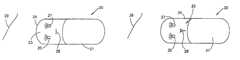
- FIGS. 2A and 2BTwo of the possible applications for the optical system of the present invention are provided as two different embodiments, illustrated in FIGS. 2A and 2B .
- FIG. 2Aillustrates a swallowable capsule which includes a) a camera system, b) an optical system for imaging an area of interest onto the camera system and c) a transmitter which transmits the video output of the camera system.
- a swallowable capsuleis disclosed in U.S. Pat. No. 5,604,531, assigned to the common assignees of the present application, which is hereby incorporated by reference.
- the swallowable capsulecan pass through the entire digestive tract and thus, operates as an autonomous video endoscope.
- the capsule, generally referenced 20is shaped as an ellipsoid.
- the capsule 20comprises a housing unit 21 and a viewing unit 23 , for viewing a target point 29 on the digestive tract wall.
- the viewing unit 23comprises an optical system according to the invention.
- the optical systemcomprises a protective optical window 24 , preferably made of isoplast, two illumination elements 25 and 27 and an imaging device 28 .
- Illumination elements 25 and 27are positioned on a focal plane perpendicular to the axis of symmetry of the ellipsoid defined by the body of the capsule 20 .
- the imaging device 28such as a camera, is positioned on the axis of symmetry of the capsule 20 .
- protective optical window 24being a single and complete unit, is easily disposable, and can be smoothly replaced between different passes through the digestive tract. This fact, which is not affordable by endoscopes described in the art, contributes to the sterile and facile use of a diagnostic device comprising the optical system of the invention.
- the present inventionprovides a simply assembled diagnostic device which can obtain data, essentially free of noise such as backscatter and stray light.
- FIG. 2Billustrates a vehicle, such as a submarine, generally referenced 30 .
- Submarine 30is shaped such that its eccentricity is equal to or larger than zero and smaller than 1.
- the submarine 30comprises a propulsion unit 31 and a viewing cell 33 , encased by window 34 , in which an operator or a monitoring device 38 are positioned on the axis of symmetry of the shape of submarine 30 .
- a target of interest 39in the deep waters, is being viewed.
- the target of interest 39is illuminated by illumination elements 35 and 37 that are positioned on a focal plane of the shape defined by the body of the submarine 30 , such that light rays internally reflected from window 34 do not blind the operator and/or are not received by monitoring device 38 .
Landscapes
- Health & Medical Sciences (AREA)
- Life Sciences & Earth Sciences (AREA)
- Physics & Mathematics (AREA)
- Surgery (AREA)
- Optics & Photonics (AREA)
- Engineering & Computer Science (AREA)
- General Health & Medical Sciences (AREA)
- Pathology (AREA)
- Radiology & Medical Imaging (AREA)
- Nuclear Medicine, Radiotherapy & Molecular Imaging (AREA)
- Biophysics (AREA)
- Biomedical Technology (AREA)
- Heart & Thoracic Surgery (AREA)
- Medical Informatics (AREA)
- Molecular Biology (AREA)
- Animal Behavior & Ethology (AREA)
- Public Health (AREA)
- Veterinary Medicine (AREA)
- General Physics & Mathematics (AREA)
- Multimedia (AREA)
- Signal Processing (AREA)
- Astronomy & Astrophysics (AREA)
- Endoscopes (AREA)
- Measurement Of The Respiration, Hearing Ability, Form, And Blood Characteristics Of Living Organisms (AREA)
- Structure And Mechanism Of Cameras (AREA)
- Instruments For Viewing The Inside Of Hollow Bodies (AREA)
- Prostheses (AREA)
- Optical Radar Systems And Details Thereof (AREA)
- Lenses (AREA)
- Glass Compositions (AREA)
- Gyroscopes (AREA)
- Medicinal Preparation (AREA)
- Formation And Processing Of Food Products (AREA)
Abstract
Description
Claims (9)
Priority Applications (2)
| Application Number | Priority Date | Filing Date | Title |
|---|---|---|---|
| US11/115,320US7433133B2 (en) | 1999-06-15 | 2005-04-27 | Optical system |
| US11/291,906US7327525B2 (en) | 1999-06-15 | 2005-12-02 | Optical system |
Applications Claiming Priority (6)
| Application Number | Priority Date | Filing Date | Title |
|---|---|---|---|
| IL13048699AIL130486A (en) | 1999-06-15 | 1999-06-15 | Optical system |
| IL130486 | 1999-06-15 | ||
| PCT/IL2000/000349WO2000076391A1 (en) | 1999-06-15 | 2000-06-15 | An optical system |
| US10/009,837US6836377B1 (en) | 1999-06-15 | 2000-06-15 | Optical system |
| US10/879,276US6934093B2 (en) | 1999-06-15 | 2004-06-30 | Optical system |
| US11/115,320US7433133B2 (en) | 1999-06-15 | 2005-04-27 | Optical system |
Related Parent Applications (1)
| Application Number | Title | Priority Date | Filing Date |
|---|---|---|---|
| US10/879,276ContinuationUS6934093B2 (en) | 1999-06-15 | 2004-06-30 | Optical system |
Related Child Applications (1)
| Application Number | Title | Priority Date | Filing Date |
|---|---|---|---|
| US11/291,906ContinuationUS7327525B2 (en) | 1999-06-15 | 2005-12-02 | Optical system |
Publications (2)
| Publication Number | Publication Date |
|---|---|
| US20050185299A1 US20050185299A1 (en) | 2005-08-25 |
| US7433133B2true US7433133B2 (en) | 2008-10-07 |
Family
ID=11072929
Family Applications (4)
| Application Number | Title | Priority Date | Filing Date |
|---|---|---|---|
| US10/009,837Expired - LifetimeUS6836377B1 (en) | 1999-06-15 | 2000-06-15 | Optical system |
| US10/879,276Expired - LifetimeUS6934093B2 (en) | 1999-06-15 | 2004-06-30 | Optical system |
| US11/115,320Expired - Fee RelatedUS7433133B2 (en) | 1999-06-15 | 2005-04-27 | Optical system |
| US11/291,906Expired - Fee RelatedUS7327525B2 (en) | 1999-06-15 | 2005-12-02 | Optical system |
Family Applications Before (2)
| Application Number | Title | Priority Date | Filing Date |
|---|---|---|---|
| US10/009,837Expired - LifetimeUS6836377B1 (en) | 1999-06-15 | 2000-06-15 | Optical system |
| US10/879,276Expired - LifetimeUS6934093B2 (en) | 1999-06-15 | 2004-06-30 | Optical system |
Family Applications After (1)
| Application Number | Title | Priority Date | Filing Date |
|---|---|---|---|
| US11/291,906Expired - Fee RelatedUS7327525B2 (en) | 1999-06-15 | 2005-12-02 | Optical system |
Country Status (9)
| Country | Link |
|---|---|
| US (4) | US6836377B1 (en) |
| EP (3) | EP1637917A1 (en) |
| JP (3) | JP3795393B2 (en) |
| AT (2) | ATE317986T1 (en) |
| AU (1) | AU5244100A (en) |
| DE (2) | DE60026025T2 (en) |
| ES (1) | ES2257299T3 (en) |
| IL (1) | IL130486A (en) |
| WO (1) | WO2000076391A1 (en) |
Cited By (4)
| Publication number | Priority date | Publication date | Assignee | Title |
|---|---|---|---|---|
| USRE41807E1 (en)* | 2002-03-08 | 2010-10-05 | Olympus Corporation | Capsule endoscope |
| US20180174318A1 (en)* | 2015-10-16 | 2018-06-21 | CapsoVision, Inc. | Method and Apparatus for Endoscope with Distance Measuring for Object Scaling |
| US10172598B2 (en) | 2012-02-17 | 2019-01-08 | Progenity, Inc. | Ingestible medical device |
| US11007356B2 (en) | 2018-11-19 | 2021-05-18 | Progenity, Inc. | Ingestible device for delivery of therapeutic agent to the gastrointestinal tract |
Families Citing this family (82)
| Publication number | Priority date | Publication date | Assignee | Title |
|---|---|---|---|---|
| MD970240A (en)* | 1997-08-29 | 1999-06-30 | Николае Павел КОВАЛЕНКО | Optical radiation photodetector |
| US10973397B2 (en) | 1999-03-01 | 2021-04-13 | West View Research, Llc | Computerized information collection and processing apparatus |
| US7914442B1 (en) | 1999-03-01 | 2011-03-29 | Gazdzinski Robert F | Endoscopic smart probe and method |
| US8636648B2 (en) | 1999-03-01 | 2014-01-28 | West View Research, Llc | Endoscopic smart probe |
| US8068897B1 (en) | 1999-03-01 | 2011-11-29 | Gazdzinski Robert F | Endoscopic smart probe and method |
| US8229549B2 (en) | 2004-07-09 | 2012-07-24 | Tyco Healthcare Group Lp | Surgical imaging device |
| US8065155B1 (en) | 1999-06-10 | 2011-11-22 | Gazdzinski Robert F | Adaptive advertising apparatus and methods |
| US7996067B2 (en)* | 1999-06-15 | 2011-08-09 | Given Imaging Ltd. | In-vivo imaging device, optical system and method |
| IL143258A0 (en)* | 2001-05-20 | 2002-04-21 | Given Imaging Ltd | A method for in vivo imaging of the gastrointestinal tract in unmodified conditions |
| US7813789B2 (en) | 1999-06-15 | 2010-10-12 | Given Imaging Ltd. | In-vivo imaging device, optical system and method |
| IL130486A (en) | 1999-06-15 | 2005-08-31 | Given Imaging Ltd | Optical system |
| IL132944A (en) | 1999-11-15 | 2009-05-04 | Arkady Glukhovsky | Method for activating an image collecting process |
| DE20122488U1 (en) | 2000-03-08 | 2005-12-15 | Given Imaging Ltd. | In vivo imaging system for use in applications such as imaging digestive tract, uses camera, illumination source and transmitter enclosed in capsule suitable for insertion into and passing through body lumens or cavities |
| US7553276B2 (en) | 2001-01-16 | 2009-06-30 | Given Imaging Ltd. | Method and device for imaging body lumens |
| EP1982636B2 (en) | 2001-06-18 | 2016-09-07 | Given Imaging Ltd. | In vivo sensing device with a circuit board having rigid sections and flexible sections |
| US6939292B2 (en)* | 2001-06-20 | 2005-09-06 | Olympus Corporation | Capsule type endoscope |
| US9149175B2 (en) | 2001-07-26 | 2015-10-06 | Given Imaging Ltd. | Apparatus and method for light control in an in-vivo imaging device |
| US9113846B2 (en) | 2001-07-26 | 2015-08-25 | Given Imaging Ltd. | In-vivo imaging device providing data compression |
| WO2003011103A2 (en) | 2001-08-02 | 2003-02-13 | Given Imaging Ltd. | Apparatus and methods for in vivo imaging |
| US6866626B2 (en) | 2001-11-09 | 2005-03-15 | Ethicon-Endo Surgery, Inc. | Self-propelled, intraluminal device with working channel and method of use |
| EP1478263B1 (en) | 2002-01-30 | 2011-03-09 | Tyco Healthcare Group LP | Surgical imaging device |
| JP3895618B2 (en) | 2002-03-08 | 2007-03-22 | オリンパス株式会社 | Capsule endoscope |
| JP4009473B2 (en) | 2002-03-08 | 2007-11-14 | オリンパス株式会社 | Capsule endoscope |
| JP2003260025A (en) | 2002-03-08 | 2003-09-16 | Olympus Optical Co Ltd | Capsule endoscope |
| US7662094B2 (en) | 2002-05-14 | 2010-02-16 | Given Imaging Ltd. | Optical head assembly with dome, and device for use thereof |
| US20040199052A1 (en) | 2003-04-01 | 2004-10-07 | Scimed Life Systems, Inc. | Endoscopic imaging system |
| US7578786B2 (en) | 2003-04-01 | 2009-08-25 | Boston Scientific Scimed, Inc. | Video endoscope |
| US8118732B2 (en) | 2003-04-01 | 2012-02-21 | Boston Scientific Scimed, Inc. | Force feedback control system for video endoscope |
| US7591783B2 (en) | 2003-04-01 | 2009-09-22 | Boston Scientific Scimed, Inc. | Articulation joint for video endoscope |
| US20050245789A1 (en) | 2003-04-01 | 2005-11-03 | Boston Scientific Scimed, Inc. | Fluid manifold for endoscope system |
| CN101264001B (en)* | 2003-04-25 | 2010-11-10 | 奥林巴斯株式会社 | Image display apparatus |
| KR20060013517A (en) | 2003-04-25 | 2006-02-10 | 올림푸스 가부시키가이샤 | Capsule Endoscope and Capsule Endoscopy System |
| JP3810381B2 (en)* | 2003-04-25 | 2006-08-16 | オリンパス株式会社 | Image display device, image display method, and image display program |
| JP2004350963A (en)* | 2003-05-29 | 2004-12-16 | Olympus Corp | Capsule type medical treatment apparatus |
| US7427024B1 (en) | 2003-12-17 | 2008-09-23 | Gazdzinski Mark J | Chattel management apparatus and methods |
| US8639314B2 (en) | 2003-12-24 | 2014-01-28 | Given Imaging Ltd. | Device, system and method for in-vivo imaging of a body lumen |
| JP2005205077A (en)* | 2004-01-26 | 2005-08-04 | Olympus Corp | Capsule type endoscope |
| CN2715696Y (en)* | 2004-02-07 | 2005-08-10 | 姜克让 | Capsule endoscope |
| US7605852B2 (en) | 2004-05-17 | 2009-10-20 | Micron Technology, Inc. | Real-time exposure control for automatic light control |
| WO2006005075A2 (en)* | 2004-06-30 | 2006-01-12 | Amir Belson | Apparatus and methods for capsule endoscopy of the esophagus |
| JP4589048B2 (en) | 2004-08-04 | 2010-12-01 | オリンパス株式会社 | Capsule endoscope |
| JP2008514363A (en) | 2004-09-30 | 2008-05-08 | ボストン サイエンティフィック リミテッド | Multifunctional endoscope system for use in electrosurgical applications |
| WO2006039522A2 (en) | 2004-09-30 | 2006-04-13 | Boston Scientific Scimed, Inc. | Adapter for use with digital imaging medical device |
| US8083671B2 (en) | 2004-09-30 | 2011-12-27 | Boston Scientific Scimed, Inc. | Fluid delivery system for use with an endoscope |
| US7241263B2 (en) | 2004-09-30 | 2007-07-10 | Scimed Life Systems, Inc. | Selectively rotatable shaft coupler |
| US7479106B2 (en) | 2004-09-30 | 2009-01-20 | Boston Scientific Scimed, Inc. | Automated control of irrigation and aspiration in a single-use endoscope |
| EP1799096A2 (en) | 2004-09-30 | 2007-06-27 | Boston Scientific Scimed, Inc. | System and method of obstruction removal |
| US7597662B2 (en) | 2004-09-30 | 2009-10-06 | Boston Scientific Scimed, Inc. | Multi-fluid delivery system |
| US8097003B2 (en) | 2005-05-13 | 2012-01-17 | Boston Scientific Scimed, Inc. | Endoscopic apparatus with integrated variceal ligation device |
| US7846107B2 (en) | 2005-05-13 | 2010-12-07 | Boston Scientific Scimed, Inc. | Endoscopic apparatus with integrated multiple biopsy device |
| JP4528216B2 (en)* | 2005-06-29 | 2010-08-18 | オリンパスメディカルシステムズ株式会社 | Endoscope |
| IL177045A (en) | 2005-07-25 | 2012-12-31 | Daniel Gat | Device, system and method of receiving and recording and displaying in-vivo data with user entered data |
| US8052597B2 (en) | 2005-08-30 | 2011-11-08 | Boston Scientific Scimed, Inc. | Method for forming an endoscope articulation joint |
| US20070156051A1 (en)* | 2005-12-29 | 2007-07-05 | Amit Pascal | Device and method for in-vivo illumination |
| US9320417B2 (en) | 2005-12-29 | 2016-04-26 | Given Imaging Ltd. | In-vivo optical imaging device with backscatter blocking |
| US20070167834A1 (en)* | 2005-12-29 | 2007-07-19 | Amit Pascal | In-vivo imaging optical device and method |
| US8773500B2 (en)* | 2006-01-18 | 2014-07-08 | Capso Vision, Inc. | In vivo image capturing system including capsule enclosing a camera |
| US7967759B2 (en) | 2006-01-19 | 2011-06-28 | Boston Scientific Scimed, Inc. | Endoscopic system with integrated patient respiratory status indicator |
| US20070255098A1 (en)* | 2006-01-19 | 2007-11-01 | Capso Vision, Inc. | System and method for in vivo imager with stabilizer |
| US8888684B2 (en) | 2006-03-27 | 2014-11-18 | Boston Scientific Scimed, Inc. | Medical devices with local drug delivery capabilities |
| US7955255B2 (en) | 2006-04-20 | 2011-06-07 | Boston Scientific Scimed, Inc. | Imaging assembly with transparent distal cap |
| US8202265B2 (en) | 2006-04-20 | 2012-06-19 | Boston Scientific Scimed, Inc. | Multiple lumen assembly for use in endoscopes or other medical devices |
| KR101026927B1 (en) | 2006-04-25 | 2011-04-04 | 올림푸스 가부시키가이샤 | Capsule Endoscope |
| US20080112885A1 (en) | 2006-09-06 | 2008-05-15 | Innurvation, Inc. | System and Method for Acoustic Data Transmission |
| EP2063766B1 (en) | 2006-09-06 | 2017-01-18 | Innurvation, Inc. | Ingestible low power sensor device and system for communicating with same |
| EP2136694A1 (en)* | 2007-03-22 | 2009-12-30 | Maquet Cardiovascular LLC | Methods and devices for viewing anatomic structure |
| US8529441B2 (en) | 2008-02-12 | 2013-09-10 | Innurvation, Inc. | Ingestible endoscopic optical scanning device |
| US20100016662A1 (en)* | 2008-02-21 | 2010-01-21 | Innurvation, Inc. | Radial Scanner Imaging System |
| US8094321B2 (en)* | 2008-02-26 | 2012-01-10 | Caterpillar Inc. | Photogrammetric target and related method |
| US8636653B2 (en) | 2008-06-09 | 2014-01-28 | Capso Vision, Inc. | In vivo camera with multiple sources to illuminate tissue at different distances |
| US8617058B2 (en) | 2008-07-09 | 2013-12-31 | Innurvation, Inc. | Displaying image data from a scanner capsule |
| US8262566B2 (en)* | 2008-07-14 | 2012-09-11 | Given Imaging Ltd. | Device and method for uniform in vivo illumination |
| US7931149B2 (en) | 2009-05-27 | 2011-04-26 | Given Imaging Ltd. | System for storing and activating an in vivo imaging capsule |
| US8516691B2 (en) | 2009-06-24 | 2013-08-27 | Given Imaging Ltd. | Method of assembly of an in vivo imaging device with a flexible circuit board |
| US8647259B2 (en) | 2010-03-26 | 2014-02-11 | Innurvation, Inc. | Ultrasound scanning capsule endoscope (USCE) |
| EP4000497A1 (en) | 2011-02-16 | 2022-05-25 | The General Hospital Corporation | Optical coupler for an endoscope |
| CN103841875A (en)* | 2012-02-10 | 2014-06-04 | 奥林巴斯医疗株式会社 | Bio-optical measurement device and measurement probe |
| US9459442B2 (en) | 2014-09-23 | 2016-10-04 | Scott Miller | Optical coupler for optical imaging visualization device |
| CN107430318B (en) | 2015-03-31 | 2020-03-24 | 富士胶片株式会社 | Ball camera and ball cover |
| US10548467B2 (en) | 2015-06-02 | 2020-02-04 | GI Scientific, LLC | Conductive optical element |
| WO2017015480A1 (en) | 2015-07-21 | 2017-01-26 | GI Scientific, LLC | Endoscope accessory with angularly adjustable exit portal |
| WO2018207254A1 (en)* | 2017-05-09 | 2018-11-15 | オリンパス株式会社 | Capsule-type endoscope |
Citations (61)
| Publication number | Priority date | Publication date | Assignee | Title |
|---|---|---|---|---|
| DE323006C (en) | 1918-08-04 | 1920-07-15 | Paul Hoegner | Double reflector |
| US3745325A (en) | 1971-08-17 | 1973-07-10 | Eastman Kodak Co | Photographic light |
| US3971362A (en) | 1972-10-27 | 1976-07-27 | The United States Of America As Represented By The Administrator Of The National Aeronautics And Space Administration | Miniature ingestible telemeter devices to measure deep-body temperature |
| US4005287A (en) | 1975-07-28 | 1977-01-25 | Recognition Equipment Incorporated | Nose attachment for OCR wand |
| US4017163A (en) | 1976-04-16 | 1977-04-12 | The United States Of America As Represented By The United States Energy Research And Development Administration | Angle amplifying optics using plane and ellipsoidal reflectors |
| US4234912A (en) | 1978-06-28 | 1980-11-18 | International Telephone And Telegraph Corporation | Luminaire for residential roadway lighting |
| US4278077A (en)* | 1978-07-27 | 1981-07-14 | Olympus Optical Co., Ltd. | Medical camera system |
| JPS5745833A (en) | 1980-09-01 | 1982-03-16 | Taeko Nakagawa | Stomack camera |
| DE3440177A1 (en) | 1984-11-02 | 1986-05-15 | Friedrich Dipl.-Ing. 8031 Eichenau Hilliges | Television recording and replay device for endoscopy on human and animal bodies |
| US4596050A (en) | 1984-04-26 | 1986-06-17 | Rogers Gordon W | Information processing system using optically encoded signals |
| US4689621A (en) | 1986-03-31 | 1987-08-25 | The United States Of America As Represented By The Administrator Of The National Aeronautics And Space Administration | Temperature responsive transmitter |
| JPS63200115A (en) | 1987-02-17 | 1988-08-18 | Olympus Optical Co Ltd | Endoscope device |
| US4819620A (en) | 1986-08-16 | 1989-04-11 | Ichiro Okutsu | Endoscope guide pipe |
| US4844076A (en) | 1988-08-26 | 1989-07-04 | The Johns Hopkins University | Ingestible size continuously transmitting temperature monitoring pill |
| DE3928515A1 (en) | 1988-12-20 | 1990-06-21 | Medizin Labortechnik Veb K | Endoscope esp. flexible blood vessel endoscope - achieves reduced dia. using bundled fibre conductors and objective made of individual elements |
| US4936823A (en) | 1988-05-04 | 1990-06-26 | Triangle Research And Development Corp. | Transendoscopic implant capsule |
| DE9016829U1 (en) | 1990-12-13 | 1991-02-28 | Aesculap AG, 7200 Tuttlingen | Rigid endoscope for medical purposes |
| US5010412A (en) | 1988-12-27 | 1991-04-23 | The Boeing Company | High frequency, low power light source for video camera |
| JPH03264037A (en) | 1990-03-14 | 1991-11-25 | Machida Endscope Co Ltd | Protecting device for endoscope |
| JPH04109927A (en) | 1990-08-31 | 1992-04-10 | Toshiba Corp | Electronic endoscope apparatus |
| JPH04144533A (en) | 1990-10-05 | 1992-05-19 | Olympus Optical Co Ltd | Endoscope |
| JPH0515515A (en) | 1991-02-19 | 1993-01-26 | Nissin Electric Co Ltd | Digestive organ system diagnosing apparatus |
| US5279607A (en) | 1991-05-30 | 1994-01-18 | The State University Of New York | Telemetry capsule and process |
| EP0667115A1 (en) | 1994-01-17 | 1995-08-16 | State Of Israel - Ministry Of Defence | An "in vivo" video camera system |
| JPH08248326A (en) | 1995-03-10 | 1996-09-27 | Olympus Optical Co Ltd | Stereoscopic endoscope |
| US5681260A (en)* | 1989-09-22 | 1997-10-28 | Olympus Optical Co., Ltd. | Guiding apparatus for guiding an insertable body within an inspected object |
| US5697384A (en) | 1993-03-26 | 1997-12-16 | Surge Miyawaki Co., Ltd. | Internal identification apparatus for animals |
| US5718663A (en) | 1995-07-17 | 1998-02-17 | Olympus Winter & Ibe Gmbh | Endoscope optical system with a window plate having a light screen |
| WO1998011816A1 (en) | 1996-09-18 | 1998-03-26 | University College London | Imaging apparatus |
| US5764274A (en) | 1996-02-16 | 1998-06-09 | Presstek, Inc. | Apparatus for laser-discharge imaging and focusing elements for use therewith |
| US5819736A (en) | 1994-03-24 | 1998-10-13 | Sightline Technologies Ltd. | Viewing method and apparatus particularly useful for viewing the interior of the large intestine |
| US5840014A (en) | 1997-01-14 | 1998-11-24 | Fuji Photo Optical Co., Ltd. | Endoscope |
| JPH11142933A (en) | 1997-11-13 | 1999-05-28 | Takashi Kawakami | Waterproof camera |
| EP0941691A1 (en) | 1998-03-11 | 1999-09-15 | Welch Allyn, Inc. | Compact video imaging assembly |
| US5993378A (en) | 1980-10-28 | 1999-11-30 | Lemelson; Jerome H. | Electro-optical instruments and methods for treating disease |
| WO2000022975A1 (en) | 1998-10-22 | 2000-04-27 | Given Imaging Ltd. | A method for delivering a device to a target location |
| WO2000076391A1 (en) | 1999-06-15 | 2000-12-21 | Given Imaging Ltd. | An optical system |
| WO2001008548A1 (en) | 1999-08-03 | 2001-02-08 | The University College London Hospitals Nhs Trust | Improved passage-travelling device |
| US6240312B1 (en)* | 1997-10-23 | 2001-05-29 | Robert R. Alfano | Remote-controllable, micro-scale device for use in in vivo medical diagnosis and/or treatment |
| WO2001065995A2 (en) | 2000-03-08 | 2001-09-13 | Given Imaging Ltd. | A device and system for in vivo imaging |
| JP3264037B2 (en) | 1993-04-28 | 2002-03-11 | 株式会社村田製作所 | Capacitor array |
| US6416181B1 (en) | 2000-12-15 | 2002-07-09 | Eastman Kodak Company | Monocentric autostereoscopic optical apparatus and method |
| WO2002055126A2 (en) | 2001-01-11 | 2002-07-18 | Given Imaging Ltd. | Device and system for in-vivo procedures |
| US20020103417A1 (en) | 1999-03-01 | 2002-08-01 | Gazdzinski Robert F. | Endoscopic smart probe and method |
| US6428469B1 (en)* | 1997-12-15 | 2002-08-06 | Given Imaging Ltd | Energy management of a video capsule |
| WO2002095351A2 (en) | 2001-05-20 | 2002-11-28 | Given Imaging Ltd. | A floatable in vivo sensing device |
| US20020198439A1 (en)* | 2001-06-20 | 2002-12-26 | Olympus Optical Co., Ltd. | Capsule type endoscope |
| US6511182B1 (en) | 2001-11-13 | 2003-01-28 | Eastman Kodak Company | Autostereoscopic optical apparatus using a scanned linear image source |
| US20030020810A1 (en)* | 2001-07-30 | 2003-01-30 | Olympus Optical Co., Ltd. | Capsule-type medical apparatus |
| US6612701B2 (en) | 2001-08-20 | 2003-09-02 | Optical Products Development Corporation | Image enhancement in a real image projection system, using on-axis reflectors, at least one of which is aspheric in shape |
| US20030167000A1 (en) | 2000-02-08 | 2003-09-04 | Tarun Mullick | Miniature ingestible capsule |
| US20030171649A1 (en)* | 2002-03-08 | 2003-09-11 | Takeshi Yokoi | Capsule endoscope |
| US20030171652A1 (en) | 2002-03-08 | 2003-09-11 | Takeshi Yokoi | Capsule endoscope |
| US20030171648A1 (en)* | 2002-03-08 | 2003-09-11 | Takeshi Yokoi | Capsule endoscope |
| US20030208107A1 (en) | 2000-01-13 | 2003-11-06 | Moshe Refael | Encapsulated medical imaging device and method |
| US6709387B1 (en)* | 2000-05-15 | 2004-03-23 | Given Imaging Ltd. | System and method for controlling in vivo camera capture and display rate |
| WO2004035106A2 (en) | 2002-10-21 | 2004-04-29 | Given Imaging Ltd. | Intubation and imaging device and system |
| US20040171914A1 (en)* | 2001-06-18 | 2004-09-02 | Dov Avni | In vivo sensing device with a circuit board having rigid sections and flexible sections |
| JP2005003828A (en) | 2003-06-10 | 2005-01-06 | Sony Corp | Hologram recording apparatus and hologram recording method |
| US20050068416A1 (en) | 1999-06-15 | 2005-03-31 | Arkady Glukhovsky | In-vivo imaging device, optical system and method |
| JP4109927B2 (en) | 2002-08-20 | 2008-07-02 | セイコークロック株式会社 | Radio correction watch and method |
Family Cites Families (64)
| Publication number | Priority date | Publication date | Assignee | Title |
|---|---|---|---|---|
| US3289779A (en) | 1965-02-01 | 1966-12-06 | Westinghouse Air Brake Co | Mobile rock drill carrier suspension system |
| US3683389A (en) | 1971-01-20 | 1972-08-08 | Corning Glass Works | Omnidirectional loop antenna array |
| US4027510A (en) | 1974-05-15 | 1977-06-07 | Siegfried Hiltebrandt | Forceps |
| US4239040A (en) | 1976-10-19 | 1980-12-16 | Kabushiki Kaisha Daini Seikosha | Capsule for medical use |
| JPS5394515A (en) | 1977-01-31 | 1978-08-18 | Kubota Ltd | Method of producing glass fiber reinforced cement plate |
| JPS5479581A (en)* | 1977-12-07 | 1979-06-25 | Seiko Instr & Electronics Ltd | Thickness-width slide crystal vibrator |
| US4177800A (en) | 1978-04-10 | 1979-12-11 | Enger Carl C | Implantable biotelemetry transmitter and method of using same |
| US4217045A (en) | 1978-12-29 | 1980-08-12 | Ziskind Stanley H | Capsule for photographic use in a walled organ of the living body |
| JPS57156736A (en) | 1981-03-23 | 1982-09-28 | Olympus Optical Co | Therapeutic capsule apparatus |
| US4491865A (en) | 1982-09-29 | 1985-01-01 | Welch Allyn, Inc. | Image sensor assembly |
| DE3337455A1 (en) | 1982-10-15 | 1984-04-19 | Olympus Optical Co., Ltd., Tokio/Tokyo | ENDOSCOPIC PHOTOGRAPHER |
| JPH0664243B2 (en) | 1986-04-30 | 1994-08-22 | オリンパス光学工業株式会社 | Endoscope |
| US4735214A (en) | 1986-09-05 | 1988-04-05 | Berman Irwin R | Gastrointestinal diagnostic capsule and method of use |
| US4917097A (en) | 1987-10-27 | 1990-04-17 | Endosonics Corporation | Apparatus and method for imaging small cavities |
| JP2693978B2 (en) | 1988-02-26 | 1997-12-24 | オリンパス光学工業株式会社 | Electronic endoscope device |
| DE3921233A1 (en) | 1989-06-28 | 1991-02-14 | Storz Karl Gmbh & Co | ENDOSCOPE WITH A VIDEO DEVICE AT THE DISTAL END |
| EP0419729A1 (en) | 1989-09-29 | 1991-04-03 | Siemens Aktiengesellschaft | Position finding of a catheter by means of non-ionising fields |
| JP2579372B2 (en) | 1989-12-04 | 1997-02-05 | 日本テキサス・インスツルメンツ株式会社 | Low power imaging device |
| GB9018660D0 (en) | 1990-08-24 | 1990-10-10 | Imperial College | Probe system |
| JP3164609B2 (en) | 1990-10-31 | 2001-05-08 | オリンパス光学工業株式会社 | Endoscope device |
| JP2948900B2 (en) | 1990-11-16 | 1999-09-13 | オリンパス光学工業株式会社 | Medical capsule |
| US5267033A (en) | 1990-11-28 | 1993-11-30 | Dai Nippon Printing Co., Ltd. | Hollow body inspection system, hollow body inspection apparatus and signal transmission apparatus |
| US5217449A (en) | 1990-12-11 | 1993-06-08 | Miyarisan Kabushiki Kaisha | Medical capsule and apparatus for activating the same |
| US5395366A (en) | 1991-05-30 | 1995-03-07 | The State University Of New York | Sampling capsule and process |
| US5222477A (en) | 1991-09-30 | 1993-06-29 | Welch Allyn, Inc. | Endoscope or borescope stereo viewing system |
| AT399229B (en) | 1992-04-23 | 1995-04-25 | Avl Verbrennungskraft Messtech | SENSOR ARRANGEMENT FOR DIRECT OR INDIRECT OPTICAL DETERMINATION OF PHYSICAL OR CHEMICAL PARAMETERS |
| JPH0663051A (en) | 1992-08-20 | 1994-03-08 | Olympus Optical Co Ltd | Capsule device for medical treatment |
| JP3631257B2 (en) | 1992-08-28 | 2005-03-23 | オリンパス株式会社 | Electronic endoscope device |
| US5662587A (en) | 1992-09-16 | 1997-09-02 | Cedars Sinai Medical Center | Robotic endoscopy |
| US5495114A (en) | 1992-09-30 | 1996-02-27 | Adair; Edwin L. | Miniaturized electronic imaging chip |
| US5373840A (en) | 1992-10-02 | 1994-12-20 | Knighton; David R. | Endoscope and method for vein removal |
| JPH06114037A (en) | 1992-10-05 | 1994-04-26 | Olympus Optical Co Ltd | Capsule device for medical treatment |
| US5603687A (en) | 1992-10-28 | 1997-02-18 | Oktas General Partnership | Asymmetric stereo-optic endoscope |
| JP3285235B2 (en) | 1992-11-05 | 2002-05-27 | オリンパス光学工業株式会社 | Capsule device for in vivo observation |
| US5653677A (en) | 1994-04-12 | 1997-08-05 | Fuji Photo Optical Co. Ltd | Electronic endoscope apparatus with imaging unit separable therefrom |
| IL110475A (en) | 1994-07-27 | 2000-11-21 | Given Imaging Ltd | Optical system for flexible tubes |
| JP3862313B2 (en) | 1995-02-15 | 2006-12-27 | キヤノン株式会社 | Image heating device |
| US5833603A (en) | 1996-03-13 | 1998-11-10 | Lipomatrix, Inc. | Implantable biosensing transponder |
| US6632171B2 (en) | 1997-12-22 | 2003-10-14 | Given Imaging Ltd. | Method for in vivo delivery of autonomous capsule |
| US7116352B2 (en) | 1999-02-25 | 2006-10-03 | Visionsense Ltd. | Capsule |
| JP3289779B2 (en) | 1999-07-30 | 2002-06-10 | 日本軽金属株式会社 | Method for producing hollow panel structure and hollow extruded profile for the production |
| JP4295865B2 (en) | 1999-08-06 | 2009-07-15 | Hoya株式会社 | Radio capsule receiving system |
| JP2001091860A (en) | 1999-09-22 | 2001-04-06 | Asahi Optical Co Ltd | Capsule endoscope |
| JP2001095755A (en) | 1999-09-30 | 2001-04-10 | Asahi Optical Co Ltd | Capsule endoscope |
| JP2001095756A (en) | 1999-09-30 | 2001-04-10 | Asahi Optical Co Ltd | Capsule endoscope |
| JP2001104243A (en) | 1999-10-04 | 2001-04-17 | Asahi Optical Co Ltd | Capsule endoscope |
| JP2001104244A (en) | 1999-10-04 | 2001-04-17 | Asahi Optical Co Ltd | Capsule endoscope |
| JP2001104287A (en) | 1999-10-04 | 2001-04-17 | Asahi Optical Co Ltd | Capsule endoscope |
| JP2001104242A (en) | 1999-10-04 | 2001-04-17 | Asahi Optical Co Ltd | Capsule endoscope |
| JP2001104241A (en) | 1999-10-04 | 2001-04-17 | Asahi Optical Co Ltd | Capsule endoscope |
| JP4472069B2 (en) | 1999-11-10 | 2010-06-02 | オリンパス株式会社 | Medical capsule endoscope |
| JP2001170002A (en) | 1999-12-20 | 2001-06-26 | Asahi Optical Co Ltd | Endoscopes and capsule endoscopes |
| JP4272783B2 (en) | 1999-12-21 | 2009-06-03 | Hoya株式会社 | Objective optical system and endoscope objective optical system |
| JP4338280B2 (en) | 2000-02-15 | 2009-10-07 | Hoya株式会社 | Capsule endoscope |
| JP4360729B2 (en) | 2000-02-15 | 2009-11-11 | Hoya株式会社 | Capsule endoscope |
| JP2001224553A (en) | 2000-02-17 | 2001-08-21 | Asahi Optical Co Ltd | Imaging device for capsule endoscope |
| JP4360730B2 (en) | 2000-02-21 | 2009-11-11 | Hoya株式会社 | Capsule endoscope |
| JP2001245844A (en) | 2000-03-03 | 2001-09-11 | Asahi Optical Co Ltd | Capsule endoscope |
| AU6057801A (en) | 2000-05-23 | 2001-12-03 | Given Imaging Ltd. | Device and method for positioning an object in a body lumen |
| US6632175B1 (en) | 2000-11-08 | 2003-10-14 | Hewlett-Packard Development Company, L.P. | Swallowable data recorder capsule medical device |
| IL143259A (en) | 2001-05-20 | 2006-08-01 | Given Imaging Ltd | Method for moving an object through the colon |
| WO2003011103A2 (en) | 2001-08-02 | 2003-02-13 | Given Imaging Ltd. | Apparatus and methods for in vivo imaging |
| JP3974769B2 (en) | 2001-11-06 | 2007-09-12 | オリンパス株式会社 | Capsule medical device |
| JP2005106614A (en)* | 2003-09-30 | 2005-04-21 | Tdk Corp | Jig for calibrating three-dimensional camera, and method for calibrating camera |
- 1999
- 1999-06-15ILIL13048699Apatent/IL130486A/ennot_activeIP Right Cessation
- 2000
- 2000-06-15DEDE60026025Tpatent/DE60026025T2/ennot_activeExpired - Lifetime
- 2000-06-15EPEP05026710Apatent/EP1637917A1/ennot_activeCeased
- 2000-06-15DEDE60040310Tpatent/DE60040310D1/ennot_activeExpired - Lifetime
- 2000-06-15EPEP06022666Apatent/EP1741382B1/ennot_activeExpired - Lifetime
- 2000-06-15ESES00937157Tpatent/ES2257299T3/ennot_activeExpired - Lifetime
- 2000-06-15WOPCT/IL2000/000349patent/WO2000076391A1/enactiveIP Right Grant
- 2000-06-15JPJP2001502738Apatent/JP3795393B2/ennot_activeExpired - Lifetime
- 2000-06-15AUAU52441/00Apatent/AU5244100A/ennot_activeAbandoned
- 2000-06-15ATAT00937157Tpatent/ATE317986T1/ennot_activeIP Right Cessation
- 2000-06-15EPEP00937157Apatent/EP1199975B1/ennot_activeExpired - Lifetime
- 2000-06-15ATAT06022666Tpatent/ATE408367T1/ennot_activeIP Right Cessation
- 2000-06-15USUS10/009,837patent/US6836377B1/ennot_activeExpired - Lifetime
- 2004
- 2004-06-30USUS10/879,276patent/US6934093B2/ennot_activeExpired - Lifetime
- 2005
- 2005-04-27USUS11/115,320patent/US7433133B2/ennot_activeExpired - Fee Related
- 2005-05-27JPJP2005155953Apatent/JP3795513B2/ennot_activeExpired - Lifetime
- 2005-05-30JPJP2005003828Upatent/JP3114298U/ennot_activeExpired - Lifetime
- 2005-12-02USUS11/291,906patent/US7327525B2/ennot_activeExpired - Fee Related
Patent Citations (68)
| Publication number | Priority date | Publication date | Assignee | Title |
|---|---|---|---|---|
| DE323006C (en) | 1918-08-04 | 1920-07-15 | Paul Hoegner | Double reflector |
| US3745325A (en) | 1971-08-17 | 1973-07-10 | Eastman Kodak Co | Photographic light |
| US3971362A (en) | 1972-10-27 | 1976-07-27 | The United States Of America As Represented By The Administrator Of The National Aeronautics And Space Administration | Miniature ingestible telemeter devices to measure deep-body temperature |
| US4005287A (en) | 1975-07-28 | 1977-01-25 | Recognition Equipment Incorporated | Nose attachment for OCR wand |
| US4017163A (en) | 1976-04-16 | 1977-04-12 | The United States Of America As Represented By The United States Energy Research And Development Administration | Angle amplifying optics using plane and ellipsoidal reflectors |
| US4234912A (en) | 1978-06-28 | 1980-11-18 | International Telephone And Telegraph Corporation | Luminaire for residential roadway lighting |
| US4278077A (en)* | 1978-07-27 | 1981-07-14 | Olympus Optical Co., Ltd. | Medical camera system |
| JPS5745833A (en) | 1980-09-01 | 1982-03-16 | Taeko Nakagawa | Stomack camera |
| US5993378A (en) | 1980-10-28 | 1999-11-30 | Lemelson; Jerome H. | Electro-optical instruments and methods for treating disease |
| US4596050A (en) | 1984-04-26 | 1986-06-17 | Rogers Gordon W | Information processing system using optically encoded signals |
| DE3440177A1 (en) | 1984-11-02 | 1986-05-15 | Friedrich Dipl.-Ing. 8031 Eichenau Hilliges | Television recording and replay device for endoscopy on human and animal bodies |
| US4689621A (en) | 1986-03-31 | 1987-08-25 | The United States Of America As Represented By The Administrator Of The National Aeronautics And Space Administration | Temperature responsive transmitter |
| US4819620A (en) | 1986-08-16 | 1989-04-11 | Ichiro Okutsu | Endoscope guide pipe |
| JPS63200115A (en) | 1987-02-17 | 1988-08-18 | Olympus Optical Co Ltd | Endoscope device |
| US4936823A (en) | 1988-05-04 | 1990-06-26 | Triangle Research And Development Corp. | Transendoscopic implant capsule |
| US4844076A (en) | 1988-08-26 | 1989-07-04 | The Johns Hopkins University | Ingestible size continuously transmitting temperature monitoring pill |
| DE3928515A1 (en) | 1988-12-20 | 1990-06-21 | Medizin Labortechnik Veb K | Endoscope esp. flexible blood vessel endoscope - achieves reduced dia. using bundled fibre conductors and objective made of individual elements |
| US5010412A (en) | 1988-12-27 | 1991-04-23 | The Boeing Company | High frequency, low power light source for video camera |
| US5681260A (en)* | 1989-09-22 | 1997-10-28 | Olympus Optical Co., Ltd. | Guiding apparatus for guiding an insertable body within an inspected object |
| JPH03264037A (en) | 1990-03-14 | 1991-11-25 | Machida Endscope Co Ltd | Protecting device for endoscope |
| JPH04109927A (en) | 1990-08-31 | 1992-04-10 | Toshiba Corp | Electronic endoscope apparatus |
| JPH04144533A (en) | 1990-10-05 | 1992-05-19 | Olympus Optical Co Ltd | Endoscope |
| DE9016829U1 (en) | 1990-12-13 | 1991-02-28 | Aesculap AG, 7200 Tuttlingen | Rigid endoscope for medical purposes |
| JPH0515515A (en) | 1991-02-19 | 1993-01-26 | Nissin Electric Co Ltd | Digestive organ system diagnosing apparatus |
| US5279607A (en) | 1991-05-30 | 1994-01-18 | The State University Of New York | Telemetry capsule and process |
| US5697384A (en) | 1993-03-26 | 1997-12-16 | Surge Miyawaki Co., Ltd. | Internal identification apparatus for animals |
| JP3264037B2 (en) | 1993-04-28 | 2002-03-11 | 株式会社村田製作所 | Capacitor array |
| EP0667115A1 (en) | 1994-01-17 | 1995-08-16 | State Of Israel - Ministry Of Defence | An "in vivo" video camera system |
| US5604531A (en)* | 1994-01-17 | 1997-02-18 | State Of Israel, Ministry Of Defense, Armament Development Authority | In vivo video camera system |
| US5819736A (en) | 1994-03-24 | 1998-10-13 | Sightline Technologies Ltd. | Viewing method and apparatus particularly useful for viewing the interior of the large intestine |
| JPH08248326A (en) | 1995-03-10 | 1996-09-27 | Olympus Optical Co Ltd | Stereoscopic endoscope |
| US5718663A (en) | 1995-07-17 | 1998-02-17 | Olympus Winter & Ibe Gmbh | Endoscope optical system with a window plate having a light screen |
| US5764274A (en) | 1996-02-16 | 1998-06-09 | Presstek, Inc. | Apparatus for laser-discharge imaging and focusing elements for use therewith |
| WO1998011816A1 (en) | 1996-09-18 | 1998-03-26 | University College London | Imaging apparatus |
| US5840014A (en) | 1997-01-14 | 1998-11-24 | Fuji Photo Optical Co., Ltd. | Endoscope |
| US6240312B1 (en)* | 1997-10-23 | 2001-05-29 | Robert R. Alfano | Remote-controllable, micro-scale device for use in in vivo medical diagnosis and/or treatment |
| JPH11142933A (en) | 1997-11-13 | 1999-05-28 | Takashi Kawakami | Waterproof camera |
| US6428469B1 (en)* | 1997-12-15 | 2002-08-06 | Given Imaging Ltd | Energy management of a video capsule |
| US6764440B2 (en)* | 1997-12-15 | 2004-07-20 | Given Imaging Ltd. | Energy management of a video capsule |
| EP0941691A1 (en) | 1998-03-11 | 1999-09-15 | Welch Allyn, Inc. | Compact video imaging assembly |
| WO2000022975A1 (en) | 1998-10-22 | 2000-04-27 | Given Imaging Ltd. | A method for delivering a device to a target location |
| US20020103417A1 (en) | 1999-03-01 | 2002-08-01 | Gazdzinski Robert F. | Endoscopic smart probe and method |
| WO2000076391A1 (en) | 1999-06-15 | 2000-12-21 | Given Imaging Ltd. | An optical system |
| US20050185299A1 (en) | 1999-06-15 | 2005-08-25 | Given Imaging Ltd. | Optical system |
| US6934093B2 (en)* | 1999-06-15 | 2005-08-23 | Given Imaging Ltd | Optical system |
| US20050068416A1 (en) | 1999-06-15 | 2005-03-31 | Arkady Glukhovsky | In-vivo imaging device, optical system and method |
| US6836377B1 (en) | 1999-06-15 | 2004-12-28 | Given Imaging Ltd. | Optical system |
| WO2001008548A1 (en) | 1999-08-03 | 2001-02-08 | The University College London Hospitals Nhs Trust | Improved passage-travelling device |
| US20030208107A1 (en) | 2000-01-13 | 2003-11-06 | Moshe Refael | Encapsulated medical imaging device and method |
| US20030167000A1 (en) | 2000-02-08 | 2003-09-04 | Tarun Mullick | Miniature ingestible capsule |
| WO2001065995A2 (en) | 2000-03-08 | 2001-09-13 | Given Imaging Ltd. | A device and system for in vivo imaging |
| US7009634B2 (en) | 2000-03-08 | 2006-03-07 | Given Imaging Ltd. | Device for in-vivo imaging |
| US6709387B1 (en)* | 2000-05-15 | 2004-03-23 | Given Imaging Ltd. | System and method for controlling in vivo camera capture and display rate |
| US20040073087A1 (en)* | 2000-05-15 | 2004-04-15 | Arkady Glukhovsky | System and method for controlling in vivo camera capture and display rate |
| US6416181B1 (en) | 2000-12-15 | 2002-07-09 | Eastman Kodak Company | Monocentric autostereoscopic optical apparatus and method |
| WO2002055126A2 (en) | 2001-01-11 | 2002-07-18 | Given Imaging Ltd. | Device and system for in-vivo procedures |
| WO2002095351A2 (en) | 2001-05-20 | 2002-11-28 | Given Imaging Ltd. | A floatable in vivo sensing device |
| US20040171914A1 (en)* | 2001-06-18 | 2004-09-02 | Dov Avni | In vivo sensing device with a circuit board having rigid sections and flexible sections |
| US20020198439A1 (en)* | 2001-06-20 | 2002-12-26 | Olympus Optical Co., Ltd. | Capsule type endoscope |
| US20030020810A1 (en)* | 2001-07-30 | 2003-01-30 | Olympus Optical Co., Ltd. | Capsule-type medical apparatus |
| US6612701B2 (en) | 2001-08-20 | 2003-09-02 | Optical Products Development Corporation | Image enhancement in a real image projection system, using on-axis reflectors, at least one of which is aspheric in shape |
| US6511182B1 (en) | 2001-11-13 | 2003-01-28 | Eastman Kodak Company | Autostereoscopic optical apparatus using a scanned linear image source |
| US20030171648A1 (en)* | 2002-03-08 | 2003-09-11 | Takeshi Yokoi | Capsule endoscope |
| US20030171652A1 (en) | 2002-03-08 | 2003-09-11 | Takeshi Yokoi | Capsule endoscope |
| US20030171649A1 (en)* | 2002-03-08 | 2003-09-11 | Takeshi Yokoi | Capsule endoscope |
| JP4109927B2 (en) | 2002-08-20 | 2008-07-02 | セイコークロック株式会社 | Radio correction watch and method |
| WO2004035106A2 (en) | 2002-10-21 | 2004-04-29 | Given Imaging Ltd. | Intubation and imaging device and system |
| JP2005003828A (en) | 2003-06-10 | 2005-01-06 | Sony Corp | Hologram recording apparatus and hologram recording method |
Non-Patent Citations (17)
| Title |
|---|
| BBC News Online-"Pill camera to 'broadcast from the gut'" Feb. 21, 2000 www news bbc co uk. |
| European Office Action Dated Nov. 16, 2006 Application 05026710.3. |
| European Search Report Dated Jan. 18, 2006 Application 05026710.3. |
| European Search Report of European Application 00937157 6, dated Feb. 3, 2004. |
| European Search Report. Application No. EP 06022666. Date of completion of the search Dec. 4, 2006. |
| Japanese Office Action Dated Aug. 2, 2005 Application 2001-502738. |
| Japanese Office Action Dated Aug. 2, 2005 Application 2005-155953. |
| Katgraber F Glenewinkel F. Fischler S. Int J Legal Med 1998; 111(3) 154-6. |
| Manual of Photogrammetry, Thompson (Ed ), Third Edition, vol. Two, American Society of Photogrammetry. 1966. |
| The Radio Pill. Rowlands,et al , British Communications and Electronics Aug. 1960 pp. 598-601. |
| U.S. Appl. No. 11/221,841, filed Sep. 9, 2005, Glukhovsky. |
| U.S. Appl. No. 11/291,906, filed Dec. 2, 2005, Kislev et al. |
| US Office Action for U.S. Appl. No. 10/009,837 dated Apr. 30, 2004. |
| US Office Action for U.S. Appl. No. 10/009,837 dated Oct. 2, 2003. |
| US Office Action for U.S. Appl. No. 10/879,276 dated Dec. 14, 2004. |
| Wellesley company sends body montiors into space-Crum Apr. 1998. |
| Wireless transmission of a color television moving image from the stomach using a miniature CCD camera, light source and microwave transmitter . Swain CP Gong F Mills TN Gastrointest Endosc 1997;45:AB40. |
Cited By (6)
| Publication number | Priority date | Publication date | Assignee | Title |
|---|---|---|---|---|
| USRE41807E1 (en)* | 2002-03-08 | 2010-10-05 | Olympus Corporation | Capsule endoscope |
| US10172598B2 (en) | 2012-02-17 | 2019-01-08 | Progenity, Inc. | Ingestible medical device |
| US20180174318A1 (en)* | 2015-10-16 | 2018-06-21 | CapsoVision, Inc. | Method and Apparatus for Endoscope with Distance Measuring for Object Scaling |
| US10402992B2 (en)* | 2015-10-16 | 2019-09-03 | Capsovision Inc. | Method and apparatus for endoscope with distance measuring for object scaling |
| US11007356B2 (en) | 2018-11-19 | 2021-05-18 | Progenity, Inc. | Ingestible device for delivery of therapeutic agent to the gastrointestinal tract |
| US11439802B2 (en) | 2018-11-19 | 2022-09-13 | Biora Therapeutics, Inc. | Ingestible device for delivery of therapeutic agent to the gastrointestinal tract |
Also Published As
| Publication number | Publication date |
|---|---|
| DE60026025T2 (en) | 2006-09-14 |
| ATE317986T1 (en) | 2006-03-15 |
| EP1199975A4 (en) | 2004-03-31 |
| US20040240077A1 (en) | 2004-12-02 |
| EP1741382A1 (en) | 2007-01-10 |
| US7327525B2 (en) | 2008-02-05 |
| JP3114298U (en) | 2005-10-27 |
| JP3795513B2 (en) | 2006-07-12 |
| EP1637917A1 (en) | 2006-03-22 |
| US6934093B2 (en) | 2005-08-23 |
| US6836377B1 (en) | 2004-12-28 |
| DE60026025D1 (en) | 2006-04-20 |
| JP2005279292A (en) | 2005-10-13 |
| ES2257299T3 (en) | 2006-08-01 |
| DE60040310D1 (en) | 2008-10-30 |
| WO2000076391A1 (en) | 2000-12-21 |
| JP2003501704A (en) | 2003-01-14 |
| AU5244100A (en) | 2001-01-02 |
| EP1199975A1 (en) | 2002-05-02 |
| IL130486A (en) | 2005-08-31 |
| US20050185299A1 (en) | 2005-08-25 |
| ATE408367T1 (en) | 2008-10-15 |
| IL130486A0 (en) | 2000-06-01 |
| EP1741382B1 (en) | 2008-09-17 |
| JP3795393B2 (en) | 2006-07-12 |
| EP1199975B1 (en) | 2006-02-15 |
| US20060122461A1 (en) | 2006-06-08 |
Similar Documents
| Publication | Publication Date | Title |
|---|---|---|
| US7433133B2 (en) | Optical system | |
| US7813789B2 (en) | In-vivo imaging device, optical system and method | |
| US8496580B2 (en) | Omnidirectional and forward-looking imaging device | |
| US6855111B2 (en) | Capsule endoscope | |
| EP0100517B1 (en) | Optical fiber sensor | |
| US8773500B2 (en) | In vivo image capturing system including capsule enclosing a camera | |
| US7996067B2 (en) | In-vivo imaging device, optical system and method | |
| EP1974240B1 (en) | In vivo sensor with panoramic camera | |
| JP5189762B2 (en) | In vivo imaging optical device | |
| JP5430175B2 (en) | Endoscope and endoscope apparatus | |
| EP0075415A2 (en) | Endoscopes provided with perspective illumination attachments | |
| IL167233A (en) | Optical system | |
| JP5362419B2 (en) | Capsule endoscope | |
| JP6865305B2 (en) | Imaging optics, endoscopes and imaging devices | |
| KR100620073B1 (en) | Human body image acquisition system and method | |
| JP2010194041A (en) | Optical system for capsule type endoscope, and capsule type endoscope | |
| KR20110061466A (en) | Camera module | |
| JP2004041457A (en) | Distal end of endoscope |
Legal Events
| Date | Code | Title | Description |
|---|---|---|---|
| AS | Assignment | Owner name:GIVEN IMAGING LID., ISRAEL Free format text:ASSIGNMENT OF ASSIGNORS INTEREST;ASSIGNORS:KISLEV, HANOCH;GLUKHOVSKY, ARKADY;MERON, GAVRIEL;AND OTHERS;REEL/FRAME:016511/0649;SIGNING DATES FROM 20020501 TO 20020819 | |
| STCF | Information on status: patent grant | Free format text:PATENTED CASE | |
| FPAY | Fee payment | Year of fee payment:4 | |
| RR | Request for reexamination filed | Effective date:20121219 | |
| B1 | Reexamination certificate first reexamination | Free format text:THE PATENTABILITY OF CLAIMS 1-5 IS CONFIRMED.CLAIM 6 IS DETERMINED TO BE PATENTABLE AS AMENDED.CLAIMS 7-9, DEPENDENT ON AN AMENDED CLAIM, ARE DETERMINED TO BE PATENTABLE. | |
| FPAY | Fee payment | Year of fee payment:8 | |
| FEPP | Fee payment procedure | Free format text:MAINTENANCE FEE REMINDER MAILED (ORIGINAL EVENT CODE: REM.); ENTITY STATUS OF PATENT OWNER: LARGE ENTITY | |
| LAPS | Lapse for failure to pay maintenance fees | Free format text:PATENT EXPIRED FOR FAILURE TO PAY MAINTENANCE FEES (ORIGINAL EVENT CODE: EXP.); ENTITY STATUS OF PATENT OWNER: LARGE ENTITY | |
| STCH | Information on status: patent discontinuation | Free format text:PATENT EXPIRED DUE TO NONPAYMENT OF MAINTENANCE FEES UNDER 37 CFR 1.362 | |
| FP | Lapsed due to failure to pay maintenance fee | Effective date:20201007 |