US7430299B2 - System and method for transmitting audio via a serial data port in a hearing instrument - Google Patents
System and method for transmitting audio via a serial data port in a hearing instrumentDownload PDFInfo
- Publication number
- US7430299B2 US7430299B2US10/822,519US82251904AUS7430299B2US 7430299 B2US7430299 B2US 7430299B2US 82251904 AUS82251904 AUS 82251904AUS 7430299 B2US7430299 B2US 7430299B2
- Authority
- US
- United States
- Prior art keywords
- hearing instrument
- signal
- audio
- digital
- external device
- Prior art date
- Legal status (The legal status is an assumption and is not a legal conclusion. Google has not performed a legal analysis and makes no representation as to the accuracy of the status listed.)
- Active, expires
Links
- 238000000034methodMethods0.000titleabstractdescription9
- 230000005236sound signalEffects0.000claimsabstractdescription76
- 238000012545processingMethods0.000claimsabstractdescription29
- 230000005540biological transmissionEffects0.000claimsabstractdescription8
- 208000016354hearing loss diseaseDiseases0.000claimsabstractdescription8
- 210000000613ear canalAnatomy0.000claimsdescription23
- 230000008878couplingEffects0.000claimsdescription4
- 238000010168coupling processMethods0.000claimsdescription4
- 238000005859coupling reactionMethods0.000claimsdescription4
- 238000012806monitoring deviceMethods0.000claimsdescription3
- 238000010586diagramMethods0.000description9
- 239000002131composite materialSubstances0.000description8
- 230000006835compressionEffects0.000description8
- 238000007906compressionMethods0.000description8
- 230000006870functionEffects0.000description8
- 230000004044responseEffects0.000description8
- 230000000694effectsEffects0.000description7
- 230000007257malfunctionEffects0.000description6
- 238000012360testing methodMethods0.000description5
- 230000003750conditioning effectEffects0.000description4
- 238000011045prefiltrationMethods0.000description4
- 238000004891communicationMethods0.000description3
- 238000005516engineering processMethods0.000description3
- 238000012544monitoring processMethods0.000description3
- 239000000523sampleSubstances0.000description3
- 206010011878DeafnessDiseases0.000description2
- 230000006727cell lossEffects0.000description2
- 238000006243chemical reactionMethods0.000description2
- 238000001514detection methodMethods0.000description2
- 230000010370hearing lossEffects0.000description2
- 231100000888hearing lossToxicity0.000description2
- 238000003780insertionMethods0.000description2
- 230000037431insertionEffects0.000description2
- 230000001575pathological effectEffects0.000description2
- 238000012805post-processingMethods0.000description2
- 230000010411postconditioningEffects0.000description2
- 230000008569processEffects0.000description2
- 230000001105regulatory effectEffects0.000description2
- 238000012546transferMethods0.000description2
- 208000003443UnconsciousnessDiseases0.000description1
- 230000003321amplificationEffects0.000description1
- 238000004458analytical methodMethods0.000description1
- 238000013459approachMethods0.000description1
- 210000004027cellAnatomy0.000description1
- 230000008859changeEffects0.000description1
- 230000001143conditioned effectEffects0.000description1
- 230000001276controlling effectEffects0.000description1
- 230000006837decompressionEffects0.000description1
- 238000002405diagnostic procedureMethods0.000description1
- 210000000959ear middleAnatomy0.000description1
- 230000007613environmental effectEffects0.000description1
- 238000001914filtrationMethods0.000description1
- 210000002768hair cellAnatomy0.000description1
- 230000001771impaired effectEffects0.000description1
- 210000000067inner hair cellAnatomy0.000description1
- 238000005259measurementMethods0.000description1
- 230000003278mimic effectEffects0.000description1
- 238000003199nucleic acid amplification methodMethods0.000description1
- 230000010355oscillationEffects0.000description1
- 238000005086pumpingMethods0.000description1
- 238000012552reviewMethods0.000description1
- 230000035945sensitivityEffects0.000description1
- 238000012549trainingMethods0.000description1
- 238000013022ventingMethods0.000description1
- 230000001755vocal effectEffects0.000description1
Images


Classifications
- H—ELECTRICITY
- H04—ELECTRIC COMMUNICATION TECHNIQUE
- H04R—LOUDSPEAKERS, MICROPHONES, GRAMOPHONE PICK-UPS OR LIKE ACOUSTIC ELECTROMECHANICAL TRANSDUCERS; DEAF-AID SETS; PUBLIC ADDRESS SYSTEMS
- H04R25/00—Deaf-aid sets, i.e. electro-acoustic or electro-mechanical hearing aids; Electric tinnitus maskers providing an auditory perception
- H04R25/70—Adaptation of deaf aid to hearing loss, e.g. initial electronic fitting
- H—ELECTRICITY
- H04—ELECTRIC COMMUNICATION TECHNIQUE
- H04R—LOUDSPEAKERS, MICROPHONES, GRAMOPHONE PICK-UPS OR LIKE ACOUSTIC ELECTROMECHANICAL TRANSDUCERS; DEAF-AID SETS; PUBLIC ADDRESS SYSTEMS
- H04R25/00—Deaf-aid sets, i.e. electro-acoustic or electro-mechanical hearing aids; Electric tinnitus maskers providing an auditory perception
- H04R25/30—Monitoring or testing of hearing aids, e.g. functioning, settings, battery power
- H—ELECTRICITY
- H04—ELECTRIC COMMUNICATION TECHNIQUE
- H04R—LOUDSPEAKERS, MICROPHONES, GRAMOPHONE PICK-UPS OR LIKE ACOUSTIC ELECTROMECHANICAL TRANSDUCERS; DEAF-AID SETS; PUBLIC ADDRESS SYSTEMS
- H04R25/00—Deaf-aid sets, i.e. electro-acoustic or electro-mechanical hearing aids; Electric tinnitus maskers providing an auditory perception
- H04R25/55—Deaf-aid sets, i.e. electro-acoustic or electro-mechanical hearing aids; Electric tinnitus maskers providing an auditory perception using an external connection, either wireless or wired
- H04R25/558—Remote control, e.g. of amplification, frequency
- H—ELECTRICITY
- H04—ELECTRIC COMMUNICATION TECHNIQUE
- H04R—LOUDSPEAKERS, MICROPHONES, GRAMOPHONE PICK-UPS OR LIKE ACOUSTIC ELECTROMECHANICAL TRANSDUCERS; DEAF-AID SETS; PUBLIC ADDRESS SYSTEMS
- H04R2225/00—Details of deaf aids covered by H04R25/00, not provided for in any of its subgroups
- H04R2225/55—Communication between hearing aids and external devices via a network for data exchange
- H—ELECTRICITY
- H04—ELECTRIC COMMUNICATION TECHNIQUE
- H04R—LOUDSPEAKERS, MICROPHONES, GRAMOPHONE PICK-UPS OR LIKE ACOUSTIC ELECTROMECHANICAL TRANSDUCERS; DEAF-AID SETS; PUBLIC ADDRESS SYSTEMS
- H04R2225/00—Details of deaf aids covered by H04R25/00, not provided for in any of its subgroups
- H04R2225/81—Aspects of electrical fitting of hearing aids related to problems arising from the emotional state of a hearing aid user, e.g. nervousness or unwillingness during fitting
- H—ELECTRICITY
- H04—ELECTRIC COMMUNICATION TECHNIQUE
- H04R—LOUDSPEAKERS, MICROPHONES, GRAMOPHONE PICK-UPS OR LIKE ACOUSTIC ELECTROMECHANICAL TRANSDUCERS; DEAF-AID SETS; PUBLIC ADDRESS SYSTEMS
- H04R2225/00—Details of deaf aids covered by H04R25/00, not provided for in any of its subgroups
- H04R2225/83—Aspects of electrical fitting of hearing aids related to problems arising from growth of the hearing aid user, e.g. children
Definitions
- the technology described in this patent documentrelates generally to the field of hearing instruments. More particularly, the patent document describes a system and method for transmitting audio via a serial data port in a hearing instrument.
- probe microphoneOne known method for monitoring hearing instrument performance is the use of a probe microphone, which may be inserted into the ear canal through the hearing aid vent.
- Probe microphonesare typically used to verify hearing instrument parameters, such as real ear insertion gain (REIG).
- REIGreal ear insertion gain
- probe microphone methodsare not widely used for a number of reasons, including the amount of effort involved, potential patient discomfort and risk, and the resultant changes to the acoustic field in the ear canal caused by insertion of the microphone.
- At least one hearing instrument microphonemay be used for receiving an audio input signal.
- a sound processormay be used for processing the audio input signal to compensate for a hearing impairment and generate a processed audio signal.
- At least one hearing instrument receivermay be used for converting the processed audio signal into an audio output signal.
- a serial data portmay be used to couple the hearing instrument to an external device in order to transmit bi-directional audio signals between the hearing instrument and the external device.
- the serial data portmay be coupled to the external device to transmit at least one of the audio input signal, the processed audio signal and the audio output signal to the external device.
- a selection circuitrymay be used to select at least one of the audio input signal, the processed audio signal and the audio output signal for transmission to the external device via the serial data port.
- FIG. 1is a block diagram illustrating an example hearing instrument having a serial data audio (SDA) port and an ear canal microphone;
- SDAserial data audio
- FIG. 2is a more-detailed block diagram of an example system for transmitting audio via a serial data port (SDA) in a hearing instrument;
- SDAserial data port
- FIGS. 4A and 4Bare a block diagram of an example digital hearing aid system that may incorporate a system for transmitting audio via a serial data port (SDA) in a hearing instrument.
- SDAserial data port
- the technology described in this patent documentutilizes a serial data (SDA) port on a hearing instrument to pass audio data between the hearing instrument and an external device, such as a computer.
- the SDA portmay be used to capture measurement data from the hearing instrument microphones and to send test stimulus to the hearing instrument receiver (i.e., the loudspeaker.)
- the SDA interfacecould be either wired or wireless.
- This technologyis particularly well-suited for use in a digital hearing instrument that includes a programming interface having an SDA port.
- the term “hearing instrument”may include any personal listening device, such as a hearing aid, wireless cell phone earpiece, etc.
- FIG. 1is a block diagram illustrating an example hearing instrument 10 having a serial data (SDA) port 20 and an ear canal microphone 16 .
- the hearing instrument 10includes a digital signal processor (DSP) 12 for controlling the operation of the hearing instrument 10 , an outer microphone 14 for receiving audio signals from outside of the ear canal; the ear canal microphone 16 for receiving audio signal from inside of the ear canal; and a loudspeaker 18 (also referred to as a receiver) for transmitting audio signals into the ear canal.
- the hearing instrument 10includes the SDA port 20 , which is operable to transmit serial data, such as an audio signal, to and from the DSP 12 .
- FIG. 1provides a simplified diagram of a hearing instrument for the purposes of illustrating the function of transmitting information over the SDA port 20 . A more detailed description of an example hearing instrument is provided below with reference to FIGS. 4A and 4B .
- audio data received by the microphones 14 , 16is routed into the digital signal processor 12 (DSP) where it can be formatted for transmission (wired or wireless) via the SDA port 20 .
- DSPdigital signal processor 12
- audio datamay be transmitted to an external device, such as a dedicated programming box, and then routed onto a PC where it can be auditioned by the audiologist via the PC's sound card and a set of speakers/headphones.
- a programming boxcould include audio equipment operable to allow the audiologist to listen to the audio directly without the aid of a PC. It should be understood, however, that audio can be routed out through the SDA line to many different types of external devices and the transmission protocol may vary.
- an audiologistcan listen to the audio in the hearing aid wearer's ear canal by streaming the audio data from the inner (ear canal) microphone out through the SDA line (after formatting and conditioning by the DSP). In this manner, the audiologist may listen in real time to the quality of the sound being delivered to the ear canal and may verify the effect of adjusting the various hearing aid parameters (such as gain, compression thresholds, tone controls, etc.).
- audio transmitted via the SDA port 20may be recorded (e.g., on a PC or other recording device) for comparison against recordings under different hearing aid configurations or even between different hearing aids.
- the recordingmay be used as a quality check or way of keeping track of the functionality of a given hearing aid over time. For example, if a patient returns at a later date with a complaint, the audiologist can make a new recording of the audio in the patient's ear canal and compare it with a previous one to determine if there has been some change in the operation or sound quality of the hearing aid.
- recordingsmay, for example, be sent to the manufacturer to help the audiologist troubleshoot malfunctioning units or to allow the manufacturer's customer support to aid in the adjustment of the hearing aid in difficult fittings.
- the recordingmay also be used as a means to provide product training to the audiologist remotely by the manufacturer.
- the inner microphonemay be used to capture otoacoustic emissions, and to route the captured emissions through the SDA line to a PC for analysis as part of a hearing and ear-health assessment.
- Audio datamay also be fed into the hearing aid to drive the loudspeaker or for other purposes. Possible examples include test signals to assess hearing loss (which might include the generation of Tartini tones), verbal instructions by an audiologist, or music.
- an audiologistmay listen directly to the audio in a patient's ear canal to determine the sound quality of the hearing aid as well as the effect of hearing aid parameter adjustments made by the audiologist. This allows the audiologist to verify directly, without relying on patient feedback, the impact of her adjustments. This is often desirable because patient feedback can be unreliable or not descriptive enough to provide the audiologist with confidence that she has fit the hearing aid optimally.
- the audiologistcan record the audio (via PC for example) and use the recording in a variety of ways.
- such recordingcould be used to: a) make a comparison of recordings between different hearing aid configurations or between different hearing aids; b) provide an indication to prospective customers what type of sound quality they can expect from such a hearing aid; c) provide a means to track and compare the sound delivered by a hearing aid over time which could be used to address customer complaints or to troubleshoot malfunctions; d) provide to the manufacturer as proof of malfunction or sub optimal quality for return for credit or to assist in fitting the hearing aid to meet a patient's specific needs (this could also be done via a live feed); e) deliver a live feed of the audio via the internet and allow an audiologist or manufacturer to assist in the fitting or assessment of the hearing aid remotely; f) allow an audiologist to monitor sound in a patient's ear canal which enables him to better
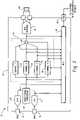
- the example sound processor 44includes a plurality of channel processors 52 , 54 , 56 , 58 for correcting hearing impairments within specific frequency bands of the received audio signal and a summation circuit for combining the processed output of the channel processors 52 , 54 , 56 , 58 into a single audio signal.
- the example hearing instrument 32also includes a digital-to-analog (D/A) converter 46 for converting the processed audio signal into an analog output that may be directed into a user's ear canal by a hearing instrument speaker 62 .
- the example hearing instrument 48includes a selection circuitry 48 (e.g., a muliplexer) and a serial data port 50 for transmitting audio signals or other data between the hearing instrument 32 and an external device.
- the selection circuitry 48may be configured to receive audio signals from any one or more of a plurality of nodes within the hearing instrument, and selectively transmit one or more of the audio signals to an external device via the SDA 50 .
- the selection circuitry 48may be configured to transmit audio signals received from the outputs of the A/D converters 38 , 40 , the output of the directional processor 42 , the outputs of the channel processors 52 , 54 , 56 , 58 , the output of the sound processor 44 , and/or other nodes within the hearing instrument 32 .
- the selection circuitry 48may, for instance, be configured by a hearing instrument user, an audiologist or by some other person or machine to select one or more of the audio signal inputs to the multiplexer 48 for transmission via the SDA 50 as a serial output.
- a control signal for configuring the selection circuitry 48may be input to the multiplexer 48 from an external device via the SDA 50 , or alternatively, the selection circuitry 48 may be programmed by some other means, such as a switch or other input device on the hearing instrument, a remote control device, or some other means for programming a digital hearing instrument.
- the selection circuitry 48may also be configured to inject audio signals or other data into any one or more of a plurality of nodes within the hearing instrument 32 .
- the selection circuitry 48may be configured to inject an audio signal or other data received from an external device via the SDA 50 into one or more of the outputs of the A/D converters 38 , 40 , the output of the directional processor 42 , the outputs of the channel processors 52 , 54 , 56 , 58 , the output of the sound processor 44 , and/or other nodes within the hearing instrument 32 .
- the selection circuitry 48may be configured to inject an audio signal into a select node within the hearing instrument 32 and transmit the audio signal from a different node over the SDA 50 .
- an audiologistmay inject an audio signal into a select node within the hearing instrument and monitor the response at a different hearing instrument node.
- an audiologistmay test the functionality of the sound processor 44 by injecting a tone or sequence of tones at the directional processor output and monitoring the response at the output of the sound processor 44 .
- the selection circuitry 48 in the illustrated embodimentincludes a multiplexer. It should be understood, however, that the hearing instrument 32 may include more than one multiplexer 48 to monitor and/or inject audio signals at nodes within the hearing instrument. In addition, selection circuitry other than a multiplexer may be used to generate a serial output from audio signals or other data received from a plurality of hearing instrument nodes and/or to inject audio signals or other data into one or more of a plurality of hearing instrument nodes.
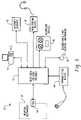
- FIG. 3is a block diagram illustrating example devices 74 , 76 , 78 , 80 , 82 , 84 that may send and/or receive audio data and other information via the serial data port (SDA) 50 in a hearing instrument 32 .
- the illustrated devicesinclude a computer 74 , an computer network (e.g., an internet) 76 , a monitoring device 78 , a recording device 80 , a second or auxiliary hearing instrument 82 and a transmitting device 84 .
- an interface device 72for communicating audio signals and other data with the SDA port 50 of the hearing instrument 32 and routing the audio signals and other data to and from one or more of the external devices 74 , 76 , 78 , 80 , 82 , 84 .
- the interface device 72may also perform other data processing functions, such as compression/decompression, coding/decoding, multiplexing/demultiplexing, serializing/deserializing, etc.
- the computer 74may, for example, be used by an audiologist to program the selection circuitry 48 in the hearing instrument 32 , inject a tone or sequence of tones into select hearing instrument nodes, monitor the output of the hearing instrument at select hearing instrument nodes, and/or perform other diagnostic functions.
- the computer network 76may, for example, be used to transmit audio signals or other data between the hearing instrument 32 and diagnostic equipment at a remote location. For instance, a hearing instrument user may be able to couple the SDA port 50 of the hearing instrument to a computer network 76 to allow an audiologist at a remote location to perform diagnostic tests on the hearing instrument.
- the monitoring device 78may, for example, be used by an audiologist or other person to listen to the output of the hearing instrument at select hearing instrument nodes. In this manner, an audiologist may effectively listen to what the hearing instrument user is hearing.
- the recording device 80may, for example, be used to record the output of the hearing instrument at select hearing instrument nodes. For instance, a hearing instrument user may attach the recording device to the SDA port 50 in order to capture a problematic audio output for later review by an audiologist.
- Other example uses of the recording device 80may include providing a means for comparing recordings of different hearing instrument configurations or different hearing instruments, providing an indication to prospective customers of the sound quality provided by a hearing instrument, providing a means to track and compare the sound delivered by a hearing aid over time, and providing proof of a malfunction or sub optimal quality.
- the second or auxiliary hearing instrument 82may be coupled to the SDA port 50 in order to transmit audio signals or other data between two hearing instruments.
- the SDA ports 50 of two hearing instrumentsmay be linked together to enable binaural applications.
- more advanced binaural algorithmsmay be utilized.
- sharing the audio signals received by the microphones in both hearing instrumentsmay enable the use of more advanced directional processing algorithms and other more-advanced signal processing applications.
- the second or auxiliary hearing instrument 82may be used for communication between two hearing instrument users.
- the transmitting device 84may, for example, be used to inject audio signals into select hearing instrument nodes. For instance, an audiologist may use the transmitting device 84 to inject spoken or recorded audio into one or more selected hearing instrument node in order to diagnose a hearing instrument malfunction, calibrate the hearing instrument, or for other purposes. In another example, the transmitting device 84 may be coupled to the SDA port 50 by a hearing instrument user for recreational purposes, such as streaming music or other recorded audio directly into the hearing instrument 32 .
- external devices 74 , 76 , 78 , 80 , 82 , 84may be coupled to the SDA port 50 of a hearing instrument 32 for other diagnostic or non-diagnostic purposes.
- external devices other than those illustrated in FIG. 3may also be used with the SDA port 50 .
- FIGS. 4A and 4Bare a block diagram of an example digital hearing aid system 1012 that may incorporate a system for transmitting audio via a serial data port (SDA) in a hearing instrument, as described herein.
- the digital hearing aid system 1012includes several external components 1014 , 1016 , 1018 , 1020 , 1022 , 1024 , 1026 , 1028 , and, preferably, a single integrated circuit (IC) 1012 A.
- the external componentsinclude a pair of microphones 1024 , 1026 , a tele-coil 1028 , a volume control potentiometer 1024 , a memory-select toggle switch 1016 , battery terminals 1018 , 1022 , and a speaker 1020 .
- Soundis received by the pair of microphones 1024 , 1026 , and converted into electrical signals that are coupled to the FMIC 1012 C and RMIC 1012 D inputs to the IC 1012 A.
- FMICrefers to “front microphone”
- RMICrefers to “rear microphone.”
- the microphones 1024 , 1026are biased between a regulated voltage output from the RREG and FREG pins 1012 B, and the ground nodes FGND 1012 F, RGND 1012 G.
- the regulated voltage output on FREG and RREGis generated internally to the IC 1012 A by regulator 1030 .
- the tele-coil 1028is a device used in a hearing aid that magnetically couples to a telephone handset and produces an input current that is proportional to the telephone signal. This input current from the tele-coil 1028 is coupled into the rear microphone A/D converter 1032 B on the IC 1012 A when the switch 1076 is connected to the “T” input pin 1012 E, indicating that the user of the hearing aid is talking on a telephone.
- the tele-coil 1028is used to prevent acoustic feedback into the system when talking on the telephone.
- the volume control potentiometer 1014is coupled to the volume control input 1012 N of the IC. This variable resistor is used to set the volume sensitivity of the digital hearing aid.
- the memory-select toggle switch 1016is coupled between the positive voltage supply VB 1018 to the IC 1012 A and the memory-select input pin 1012 L.
- This switch 1016is used to toggle the digital hearing aid system 1012 between a series of setup configurations.
- the devicemay have been previously programmed for a variety of environmental settings, such as quiet listening, listening to music, a noisy setting, etc.
- the system parameters of the IC 1012 Amay have been optimally configured for the particular user.
- the toggle switch 1016By repeatedly pressing the toggle switch 1016 , the user may then toggle through the various configurations stored in the read-only memory 1044 of the IC 1012 A.
- the battery terminals 1012 K, 1012 H of the IC 1012 Aare preferably coupled to a single 1.3 volt zinc-air battery. This battery provides the primary power source for the digital hearing aid system.
- the last external componentis the speaker 1020 .
- This elementis coupled to the differential outputs at pins 1012 J, 1012 I of the IC 1012 A, and converts the processed digital input signals from the two microphones 1024 , 1026 into an audible signal for the user of the digital hearing aid system 1012 .
- a pair of A/D converters 1032 A, 1032 Bare coupled between the front and rear microphones 1024 , 1026 , and the sound processor 1038 , and convert the analog input signals into the digital domain for digital processing by the sound processor 1038 .
- a single D/A converter 1048converts the processed digital signals back into the analog domain for output by the speaker 1020 .
- Other system elementsinclude a regulator 1030 , a volume control A/D 1040 , an interface/system controller 1042 , an EEPROM memory 1044 , a power-on reset circuit 1046 , and a oscillator/system clock 1036 .
- the sound processor 1038preferably includes a directional processor and headroom expander 1050 , a pre-filter 1052 , a wide-band twin detector 1054 , a band-split filter 1056 , a plurality of narrow-band channel processing and twin detectors 1058 A- 1058 D, a summer 1060 , a post filter 1062 , a notch filter 1064 , a volume control circuit 1066 , an automatic gain control output circuit 1068 , a peak clipping circuit 1070 , a squelch circuit 1072 , and a tone generator 1074 .
- a directional processor and headroom expander 1050preferably includes a directional processor and headroom expander 1050 , a pre-filter 1052 , a wide-band twin detector 1054 , a band-split filter 1056 , a plurality of narrow-band channel processing and twin detectors 1058 A- 1058 D, a summer 1060 , a post filter 1062 , a notch filter
- the sound processor 1038processes digital sound as follows. Sound signals input to the front and rear microphones 1024 , 1026 are coupled to the front and rear A/D converters 1032 A, 1032 B, which are preferably Sigma-Delta modulators followed by decimation filters that convert the analog sound inputs from the two microphones into a digital equivalent. Note that when a user of the digital hearing aid system is talking on the telephone, the rear A/D converter 1032 B is coupled to the tele-coil input “T” 1012 E via switch 1076 . Both of the front and rear A/D converters 1032 A, 1032 B are clocked with the output clock signal from the oscillator/system clock 1036 (discussed in more detail below). This same output clock signal is also coupled to the sound processor 1038 and the D/A converter 1048 .
- the front and rear A/D converters 1032 A, 1032 Bare preferably Sigma-Delta modulators followed by decimation filters that convert the analog sound inputs from the two microphones into a digital equivalent
- the front and rear digital sound signals from the two A/D converters 1032 A, 1032 Bare coupled to the directional processor and headroom expander 1050 of the sound processor 1038 .
- the rear A/D converter 1032 Bis coupled to the processor 1050 through switch 1075 .
- the switch 1075couples the digital output of the rear A/D converter 1032 B to the processor 1050
- the switch 1075couples the digital output of the rear A/D converter 1032 B to summation block 1071 for the purpose of compensating for occlusion.
- Occlusionis the amplification of the users own voice within the ear canal.
- the rear microphonecan be moved inside the ear canal to receive this unwanted signal created by the occlusion effect.
- the occlusion effectis usually reduced in these types of systems by putting a mechanical vent in the hearing aid. This vent, however, can cause an oscillation problem as the speaker signal feeds back to the microphone(s) through the vent aperture.
- Another problem associated with traditional ventingis a reduced low frequency response (leading to reduced sound quality).
- Yet another limitationoccurs when the direct coupling of ambient sounds results in poor directional performance, particularly in the low frequencies. The system shown in FIG.
- the directional processor and headroom expander 1050includes a combination of filtering and delay elements that, when applied to the two digital input signals, forms a single, directionally-sensitive response. This directionally-sensitive response is generated such that the gain of the directional processor 1050 will be a maximum value for sounds coming from the front microphone 1024 and will be a minimum value for sounds coming from the rear microphone 1026 .
- the headroom expander portion of the processor 1050significantly extends the dynamic range of the A/D conversion, which is very important for high fidelity audio signal processing. It does this by dynamically adjusting the A/D converters 1032 A/ 1032 B operating points.
- the headroom expander 1050adjusts the gain before and after the A/D conversion so that the total gain remains unchanged, but the intrinsic dynamic range of the A/D converter block 1032 A/ 1032 B is optimized to the level of the signal being processed.
- the output from the directional processor and headroom expander 1050is coupled to a pre-filter 1052 , which is a general-purpose filter for pre-conditioning the sound signal prior to any further signal processing steps.
- This “pre-conditioning”can take many forms, and, in combination with corresponding “post-conditioning” in the post filter 1062 , can be used to generate special effects that may be suited to only a particular class of users.
- the pre-filter 1052could be configured to mimic the transfer function of the user's middle ear, effectively putting the sound signal into the “cochlear domain.”
- Signal processing algorithms to correct a hearing impairment based on, for example, inner hair cell loss and outer hair cell loss,could be applied by the sound processor 1038 .
- the post-filter 1062could be configured with the inverse response of the pre-filter 1052 in order to convert the sound signal back into the “acoustic domain” from the “cochlear domain.”
- the post-filter 1062could be configured with the inverse response of the pre-filter 1052 in order to convert the sound signal back into the “acoustic domain” from the “cochlear domain.”
- other pre-conditioning/post-conditioning configurations and corresponding signal processing algorithmscould be utilized.
- the pre-conditioned digital sound signalis then coupled to the band-split filter 1056 , which preferably includes a bank of filters with variable corner frequencies and pass-band gains. These filters are used to split the single input signal into four distinct frequency bands.
- the four output signals from the band-split filter 1056are preferably in-phase so that when they are summed together in block 1060 , after channel processing, nulls or peaks in the composite signal (from the summer) are minimized.
- Each of the channel processing/twin detectors 1058 A- 1058 Dprovide an automatic gain control (“AGC”) function that provides compression and gain on the particular frequency band (channel) being processed. Compression of the channel signals permits quieter sounds to be amplified at a higher gain than louder sounds, for which the gain is compressed. In this manner, the user of the system can hear the full range of sounds since the circuits 1058 A- 1058 D compress the full range of normal hearing into the reduced dynamic range of the individual user as a function of the individual user's hearing loss within the particular frequency band of the channel.
- AGCautomatic gain control
- the channel processing blocks 1058 A- 1058 Dcan be configured to employ a twin detector average detection scheme while compressing the input signals.
- This twin detection schemeincludes both slow and fast attack/release tracking modules that allow for fast response to transients (in the fast tracking module), while preventing annoying pumping of the input signal (in the slow tracking module) that only a fast time constant would produce.
- the outputs of the fast and slow tracking modulesare compared, and the compression slope is then adjusted accordingly.
- the compression ratio, channel gain, lower and upper thresholds (return to linear point), and the fast and slow time constants (of the fast and slow tracking modules)can be independently programmed and saved in memory 1044 for each of the plurality of channel processing blocks 1058 A- 1058 D.
- FIG. 4also shows a communication bus 1059 , which may include one or more connections, for coupling the plurality of channel processing blocks 1058 A- 1058 D.
- This inter-channel communication bus 1059can be used to communicate information between the plurality of channel processing blocks 1058 A- 1058 D such that each channel (frequency band) can take into account the “energy” level (or some other measure) from the other channel processing blocks.
- each channel processing block 1058 A- 1058 Dwould take into account the “energy” level from the higher frequency channels.
- the “energy” level from the wide-band detector 1054may be used by each of the relatively narrow-band channel processing blocks 1058 A- 1058 D when processing their individual input signals.
- the four channel signalsare summed by summer 1060 to form a composite signal.
- This composite signalis then coupled to the post-filter 1062 , which may apply a post-processing filter function as discussed above.
- the composite signalis then applied to a notch-filter 1064 , that attenuates a narrow band of frequencies that is adjustable in the frequency range where hearing aids tend to oscillate.
- This notch filter 1064is used to reduce feedback and prevent unwanted “whistling” of the device.
- the notch filter 1064may include a dynamic transfer function that changes the depth of the notch based upon the magnitude of the input signal.
- the composite signalis then coupled to a volume control circuit 1066 .
- the volume control circuit 1066receives a digital value from the volume control A/D 1040 , which indicates the desired volume level set by the user via potentiometer 1014 , and uses this stored digital value to set the gain of an included amplifier circuit.
- the output of the squelch circuit 1072is coupled to one input of summer 1071 .
- the other input to the summer 1071is from the output of the rear A/D converter 1032 B, when the switch 1075 is in the second position.
- These two signalsare summed in summer 1071 , and passed along to the interpolator and peak clipping circuit 1070 .
- This circuit 1070also operates on pathological signals, but it operates almost instantaneously to large peak signals and is high distortion limiting.
- the interpolatorshifts the signal up in frequency as part of the D/A process and then the signal is clipped so that the distortion products do not alias back into the baseband frequency range.
Landscapes
- Health & Medical Sciences (AREA)
- General Health & Medical Sciences (AREA)
- Otolaryngology (AREA)
- Engineering & Computer Science (AREA)
- Neurosurgery (AREA)
- Physics & Mathematics (AREA)
- Acoustics & Sound (AREA)
- Signal Processing (AREA)
- Computer Networks & Wireless Communication (AREA)
- Measurement Of The Respiration, Hearing Ability, Form, And Blood Characteristics Of Living Organisms (AREA)
- Circuit For Audible Band Transducer (AREA)
- Headphones And Earphones (AREA)
Abstract
Description
Claims (11)
Priority Applications (1)
| Application Number | Priority Date | Filing Date | Title |
|---|---|---|---|
| US10/822,519US7430299B2 (en) | 2003-04-10 | 2004-04-12 | System and method for transmitting audio via a serial data port in a hearing instrument |
Applications Claiming Priority (2)
| Application Number | Priority Date | Filing Date | Title |
|---|---|---|---|
| US46194303P | 2003-04-10 | 2003-04-10 | |
| US10/822,519US7430299B2 (en) | 2003-04-10 | 2004-04-12 | System and method for transmitting audio via a serial data port in a hearing instrument |
Publications (2)
| Publication Number | Publication Date |
|---|---|
| US20040202340A1 US20040202340A1 (en) | 2004-10-14 |
| US7430299B2true US7430299B2 (en) | 2008-09-30 |
Family
ID=32869691
Family Applications (1)
| Application Number | Title | Priority Date | Filing Date |
|---|---|---|---|
| US10/822,519Active2025-12-29US7430299B2 (en) | 2003-04-10 | 2004-04-12 | System and method for transmitting audio via a serial data port in a hearing instrument |
Country Status (3)
| Country | Link |
|---|---|
| US (1) | US7430299B2 (en) |
| EP (1) | EP1467596A3 (en) |
| CA (1) | CA2464025C (en) |
Cited By (61)
| Publication number | Priority date | Publication date | Assignee | Title |
|---|---|---|---|---|
| US20060098832A1 (en)* | 2004-11-08 | 2006-05-11 | Siemens Audiologische Technik Gmbh | Method for amplifying an acoustic signal and corresponding acoustic system |
| US20090074201A1 (en)* | 2007-09-18 | 2009-03-19 | Starkey Laboratories, Inc. | Method and apparatus for microphone matching for wearable directional hearing device using wearer's own voice |
| US20100098278A1 (en)* | 2008-10-17 | 2010-04-22 | Oticon A/S | Listening system comprising a charging station with a data memory |
| US20110176686A1 (en)* | 2010-01-21 | 2011-07-21 | Richard Zaccaria | Remote Programming System for Programmable Hearing Aids |
| US20150195661A1 (en)* | 2012-07-06 | 2015-07-09 | Jocoti Bvba | Consumer Electronics Device Adapted for Hearing Loss Compensation |
| US20210067938A1 (en)* | 2013-10-06 | 2021-03-04 | Staton Techiya Llc | Methods and systems for establishing and maintaining presence information of neighboring bluetooth devices |
| US20210322223A1 (en)* | 2014-12-01 | 2021-10-21 | Staton Techiya Llc | Fixation methods for devices in tubular structures |
| US11317202B2 (en) | 2007-04-13 | 2022-04-26 | Staton Techiya, Llc | Method and device for voice operated control |
| US20220191608A1 (en) | 2011-06-01 | 2022-06-16 | Staton Techiya Llc | Methods and devices for radio frequency (rf) mitigation proximate the ear |
| US11388500B2 (en) | 2010-06-26 | 2022-07-12 | Staton Techiya, Llc | Methods and devices for occluding an ear canal having a predetermined filter characteristic |
| US11389333B2 (en) | 2009-02-13 | 2022-07-19 | Staton Techiya, Llc | Earplug and pumping systems |
| US11432065B2 (en) | 2017-10-23 | 2022-08-30 | Staton Techiya, Llc | Automatic keyword pass-through system |
| US11430422B2 (en) | 2015-05-29 | 2022-08-30 | Staton Techiya Llc | Methods and devices for attenuating sound in a conduit or chamber |
| US11443746B2 (en) | 2008-09-22 | 2022-09-13 | Staton Techiya, Llc | Personalized sound management and method |
| US11450331B2 (en) | 2006-07-08 | 2022-09-20 | Staton Techiya, Llc | Personal audio assistant device and method |
| US11451923B2 (en) | 2018-05-29 | 2022-09-20 | Staton Techiya, Llc | Location based audio signal message processing |
| US11488590B2 (en) | 2018-05-09 | 2022-11-01 | Staton Techiya Llc | Methods and systems for processing, storing, and publishing data collected by an in-ear device |
| US11489966B2 (en) | 2007-05-04 | 2022-11-01 | Staton Techiya, Llc | Method and apparatus for in-ear canal sound suppression |
| US11504067B2 (en) | 2015-05-08 | 2022-11-22 | Staton Techiya, Llc | Biometric, physiological or environmental monitoring using a closed chamber |
| US11521632B2 (en) | 2006-07-08 | 2022-12-06 | Staton Techiya, Llc | Personal audio assistant device and method |
| US11546698B2 (en) | 2011-03-18 | 2023-01-03 | Staton Techiya, Llc | Earpiece and method for forming an earpiece |
| US11550535B2 (en) | 2007-04-09 | 2023-01-10 | Staton Techiya, Llc | Always on headwear recording system |
| US11551704B2 (en) | 2013-12-23 | 2023-01-10 | Staton Techiya, Llc | Method and device for spectral expansion for an audio signal |
| US11558697B2 (en) | 2018-04-04 | 2023-01-17 | Staton Techiya, Llc | Method to acquire preferred dynamic range function for speech enhancement |
| US11589329B1 (en) | 2010-12-30 | 2023-02-21 | Staton Techiya Llc | Information processing using a population of data acquisition devices |
| US11595762B2 (en) | 2016-01-22 | 2023-02-28 | Staton Techiya Llc | System and method for efficiency among devices |
| US11595771B2 (en) | 2013-10-24 | 2023-02-28 | Staton Techiya, Llc | Method and device for recognition and arbitration of an input connection |
| US11605395B2 (en) | 2013-01-15 | 2023-03-14 | Staton Techiya, Llc | Method and device for spectral expansion of an audio signal |
| US11605456B2 (en) | 2007-02-01 | 2023-03-14 | Staton Techiya, Llc | Method and device for audio recording |
| US11607155B2 (en) | 2018-03-10 | 2023-03-21 | Staton Techiya, Llc | Method to estimate hearing impairment compensation function |
| US11638109B2 (en) | 2008-10-15 | 2023-04-25 | Staton Techiya, Llc | Device and method to reduce ear wax clogging of acoustic ports, hearing aid sealing system, and feedback reduction system |
| US11638084B2 (en) | 2018-03-09 | 2023-04-25 | Earsoft, Llc | Eartips and earphone devices, and systems and methods therefor |
| US11659315B2 (en) | 2012-12-17 | 2023-05-23 | Staton Techiya Llc | Methods and mechanisms for inflation |
| US11665493B2 (en) | 2008-09-19 | 2023-05-30 | Staton Techiya Llc | Acoustic sealing analysis system |
| US11683643B2 (en) | 2007-05-04 | 2023-06-20 | Staton Techiya Llc | Method and device for in ear canal echo suppression |
| US11693617B2 (en) | 2014-10-24 | 2023-07-04 | Staton Techiya Llc | Method and device for acute sound detection and reproduction |
| US11710473B2 (en) | 2007-01-22 | 2023-07-25 | Staton Techiya Llc | Method and device for acute sound detection and reproduction |
| US11730630B2 (en) | 2012-09-04 | 2023-08-22 | Staton Techiya Llc | Occlusion device capable of occluding an ear canal |
| US11750965B2 (en) | 2007-03-07 | 2023-09-05 | Staton Techiya, Llc | Acoustic dampening compensation system |
| US11759149B2 (en) | 2014-12-10 | 2023-09-19 | Staton Techiya Llc | Membrane and balloon systems and designs for conduits |
| US11818552B2 (en) | 2006-06-14 | 2023-11-14 | Staton Techiya Llc | Earguard monitoring system |
| US11856375B2 (en) | 2007-05-04 | 2023-12-26 | Staton Techiya Llc | Method and device for in-ear echo suppression |
| US11853405B2 (en) | 2013-08-22 | 2023-12-26 | Staton Techiya Llc | Methods and systems for a voice ID verification database and service in social networking and commercial business transactions |
| US11869526B2 (en) | 2003-04-15 | 2024-01-09 | Ipventure, Inc. | Hearing enhancement methods and systems |
| US11917100B2 (en) | 2013-09-22 | 2024-02-27 | Staton Techiya Llc | Real-time voice paging voice augmented caller ID/ring tone alias |
| US11921355B2 (en) | 2004-07-28 | 2024-03-05 | Ingeniospec, Llc | Head-worn personal audio apparatus supporting enhanced hearing support |
| US11985467B2 (en) | 2018-05-22 | 2024-05-14 | The Diablo Canyon Collective Llc | Hearing sensitivity acquisition methods and devices |
| US12001599B2 (en) | 2004-07-28 | 2024-06-04 | Ingeniospec, Llc | Head-worn device with connection region |
| US12044901B2 (en) | 2005-10-11 | 2024-07-23 | Ingeniospec, Llc | System for charging embedded battery in wireless head-worn personal electronic apparatus |
| US12045542B2 (en) | 2018-03-10 | 2024-07-23 | The Diablo Canyon Collective Llc | Earphone software and hardware |
| US12089011B2 (en) | 2008-09-11 | 2024-09-10 | St Famtech, Llc | Method and system for sound monitoring over a network |
| US12164180B2 (en) | 2003-10-09 | 2024-12-10 | Ingeniospec, Llc | Eyewear supporting distributed and embedded electronic components |
| US12174901B2 (en) | 2011-03-28 | 2024-12-24 | Apple Inc. | Methods and systems for searching utilizing acoustical context |
| US12217600B2 (en) | 2007-04-27 | 2025-02-04 | The Diablo Canyon Collective Llc | Designer control devices |
| US12242138B1 (en) | 2004-10-12 | 2025-03-04 | Ingeniospec, Llc | Wireless headset supporting messages and hearing enhancement |
| US12249326B2 (en) | 2007-04-13 | 2025-03-11 | St Case1Tech, Llc | Method and device for voice operated control |
| US12248198B2 (en) | 2005-10-11 | 2025-03-11 | Ingeniospec, Llc | Eyewear having flexible printed circuit substrate supporting electrical components |
| US12268523B2 (en) | 2015-05-08 | 2025-04-08 | ST R&DTech LLC | Biometric, physiological or environmental monitoring using a closed chamber |
| US12289576B2 (en) | 2007-07-12 | 2025-04-29 | St Tiptech, Llc | Expandable sealing devices and methods |
| US12349097B2 (en) | 2010-12-30 | 2025-07-01 | St Famtech, Llc | Information processing using a population of data acquisition devices |
| US12413892B2 (en) | 2008-10-10 | 2025-09-09 | St Tiptech, Llc | Inverted balloon system and inflation management system |
Families Citing this family (44)
| Publication number | Priority date | Publication date | Assignee | Title |
|---|---|---|---|---|
| US7650004B2 (en)* | 2001-11-15 | 2010-01-19 | Starkey Laboratories, Inc. | Hearing aids and methods and apparatus for audio fitting thereof |
| US8401212B2 (en) | 2007-10-12 | 2013-03-19 | Earlens Corporation | Multifunction system and method for integrated hearing and communication with noise cancellation and feedback management |
| US7867160B2 (en) | 2004-10-12 | 2011-01-11 | Earlens Corporation | Systems and methods for photo-mechanical hearing transduction |
| US7668325B2 (en) | 2005-05-03 | 2010-02-23 | Earlens Corporation | Hearing system having an open chamber for housing components and reducing the occlusion effect |
| EP1657958B1 (en) | 2005-06-27 | 2012-06-13 | Phonak Ag | Communication system and hearing device |
| US7986790B2 (en)* | 2006-03-14 | 2011-07-26 | Starkey Laboratories, Inc. | System for evaluating hearing assistance device settings using detected sound environment |
| US8681999B2 (en)* | 2006-10-23 | 2014-03-25 | Starkey Laboratories, Inc. | Entrainment avoidance with an auto regressive filter |
| US20100104122A1 (en)* | 2007-03-30 | 2010-04-29 | Phonak Ag | Method for establishing performance of hearing devices |
| US9191740B2 (en)* | 2007-05-04 | 2015-11-17 | Personics Holdings, Llc | Method and apparatus for in-ear canal sound suppression |
| US8526645B2 (en) | 2007-05-04 | 2013-09-03 | Personics Holdings Inc. | Method and device for in ear canal echo suppression |
| WO2008137870A1 (en)* | 2007-05-04 | 2008-11-13 | Personics Holdings Inc. | Method and device for acoustic management control of multiple microphones |
| EP2189006B1 (en)* | 2007-09-20 | 2011-06-29 | Phonak AG | Method for determining of feedback threshold in a hearing device |
| US20110026746A1 (en)* | 2007-09-20 | 2011-02-03 | Phonak Ag | Method for determining of feedback threshold in a hearing device and a hearing device |
| DE102007054603B4 (en)* | 2007-11-15 | 2018-10-18 | Sivantos Pte. Ltd. | Hearing device with controlled programming socket |
| US8718288B2 (en) | 2007-12-14 | 2014-05-06 | Starkey Laboratories, Inc. | System for customizing hearing assistance devices |
| US8571244B2 (en)* | 2008-03-25 | 2013-10-29 | Starkey Laboratories, Inc. | Apparatus and method for dynamic detection and attenuation of periodic acoustic feedback |
| US8107654B2 (en) | 2008-05-21 | 2012-01-31 | Starkey Laboratories, Inc | Mixing of in-the-ear microphone and outside-the-ear microphone signals to enhance spatial perception |
| US9485589B2 (en)* | 2008-06-02 | 2016-11-01 | Starkey Laboratories, Inc. | Enhanced dynamics processing of streaming audio by source separation and remixing |
| CN102138340B (en) | 2008-06-17 | 2014-10-08 | 依耳乐恩斯公司 | Optical electro-mechanical hearing devices with combined power and signal architectures |
| WO2009155358A1 (en) | 2008-06-17 | 2009-12-23 | Earlens Corporation | Optical electro-mechanical hearing devices with separate power and signal components |
| US8396239B2 (en)* | 2008-06-17 | 2013-03-12 | Earlens Corporation | Optical electro-mechanical hearing devices with combined power and signal architectures |
| BRPI0919266A2 (en) | 2008-09-22 | 2017-05-30 | SoundBeam LLC | device and method for transmitting an audio signal to a user, methods for manufacturing a device for transmitting an audio signal to the user, and for providing an audio device for a user, and device and method for transmitting a sound for a user. user having a tympanic membrane |
| US8359283B2 (en)* | 2009-08-31 | 2013-01-22 | Starkey Laboratories, Inc. | Genetic algorithms with robust rank estimation for hearing assistance devices |
| US9729976B2 (en)* | 2009-12-22 | 2017-08-08 | Starkey Laboratories, Inc. | Acoustic feedback event monitoring system for hearing assistance devices |
| US9654885B2 (en) | 2010-04-13 | 2017-05-16 | Starkey Laboratories, Inc. | Methods and apparatus for allocating feedback cancellation resources for hearing assistance devices |
| US8588922B1 (en)* | 2010-07-30 | 2013-11-19 | Advanced Bionics Ag | Methods and systems for presenting audible cues to assist in fitting a bilateral cochlear implant patient |
| EP2656639B1 (en) | 2010-12-20 | 2020-05-13 | Earlens Corporation | Anatomically customized ear canal hearing apparatus |
| US9479877B2 (en)* | 2011-06-21 | 2016-10-25 | Advanced Bionics Ag | Methods and systems for logging data associated with an operation of a sound processor by an auditory prosthesis |
| US10034103B2 (en) | 2014-03-18 | 2018-07-24 | Earlens Corporation | High fidelity and reduced feedback contact hearing apparatus and methods |
| DK3169396T3 (en) | 2014-07-14 | 2021-06-28 | Earlens Corp | Sliding bias and peak limitation for optical hearing aids |
| US9924276B2 (en) | 2014-11-26 | 2018-03-20 | Earlens Corporation | Adjustable venting for hearing instruments |
| DK3888564T3 (en) | 2015-10-02 | 2025-07-14 | Earlens Corp | DEVICE FOR CUSTOMIZED DELIVERY OF MEDICINE IN THE EAR CANAL |
| US10492010B2 (en) | 2015-12-30 | 2019-11-26 | Earlens Corporations | Damping in contact hearing systems |
| US11350226B2 (en) | 2015-12-30 | 2022-05-31 | Earlens Corporation | Charging protocol for rechargeable hearing systems |
| US10178483B2 (en) | 2015-12-30 | 2019-01-08 | Earlens Corporation | Light based hearing systems, apparatus, and methods |
| TWI612820B (en)* | 2016-02-03 | 2018-01-21 | 元鼎音訊股份有限公司 | Hearing aid communication system and hearing aid communication method thereof |
| EP3510796A4 (en) | 2016-09-09 | 2020-04-29 | Earlens Corporation | Contact hearing systems, apparatus and methods |
| WO2018093733A1 (en) | 2016-11-15 | 2018-05-24 | Earlens Corporation | Improved impression procedure |
| TWI623930B (en)* | 2017-03-02 | 2018-05-11 | 元鼎音訊股份有限公司 | Sounding device, audio transmission system, and audio analysis method thereof |
| US10838922B2 (en) | 2017-03-31 | 2020-11-17 | International Business Machines Corporation | Data compression by using cognitive created dictionaries |
| WO2019173470A1 (en) | 2018-03-07 | 2019-09-12 | Earlens Corporation | Contact hearing device and retention structure materials |
| WO2019199680A1 (en) | 2018-04-09 | 2019-10-17 | Earlens Corporation | Dynamic filter |
| WO2020028086A1 (en) | 2018-07-31 | 2020-02-06 | Earlens Corporation | Inductive coupling coil structure in a contact hearing system |
| CN113611266B (en)* | 2021-07-08 | 2023-10-31 | 北京小唱科技有限公司 | Audio synchronization method, device and storage medium suitable for multi-user K songs |
Citations (7)
| Publication number | Priority date | Publication date | Assignee | Title |
|---|---|---|---|---|
| DE4128172A1 (en) | 1991-08-24 | 1993-03-04 | Bosch Gmbh Robert | Digital hearing aid with microcomputer - uses acoustic sensor to pick up oto-acoustic reaction of inner ear to tones measured by electro-acoustic transducer |
| WO1999031936A1 (en) | 1997-12-18 | 1999-06-24 | Resound Corporation | Probe microphone |
| US6115478A (en)* | 1997-04-16 | 2000-09-05 | Dspfactory Ltd. | Apparatus for and method of programming a digital hearing aid |
| US6144748A (en)* | 1997-03-31 | 2000-11-07 | Resound Corporation | Standard-compatible, power efficient digital audio interface |
| US6366863B1 (en) | 1998-01-09 | 2002-04-02 | Micro Ear Technology Inc. | Portable hearing-related analysis system |
| US20030007647A1 (en) | 2001-07-09 | 2003-01-09 | Topholm & Westermann Aps | Hearing aid with a self-test capability |
| US6590986B1 (en)* | 1999-11-12 | 2003-07-08 | Siemens Hearing Instruments, Inc. | Patient-isolating programming interface for programming hearing aids |
- 2004
- 2004-04-12USUS10/822,519patent/US7430299B2/enactiveActive
- 2004-04-13EPEP04008778Apatent/EP1467596A3/ennot_activeWithdrawn
- 2004-04-13CACA002464025Apatent/CA2464025C/ennot_activeExpired - Lifetime
Patent Citations (7)
| Publication number | Priority date | Publication date | Assignee | Title |
|---|---|---|---|---|
| DE4128172A1 (en) | 1991-08-24 | 1993-03-04 | Bosch Gmbh Robert | Digital hearing aid with microcomputer - uses acoustic sensor to pick up oto-acoustic reaction of inner ear to tones measured by electro-acoustic transducer |
| US6144748A (en)* | 1997-03-31 | 2000-11-07 | Resound Corporation | Standard-compatible, power efficient digital audio interface |
| US6115478A (en)* | 1997-04-16 | 2000-09-05 | Dspfactory Ltd. | Apparatus for and method of programming a digital hearing aid |
| WO1999031936A1 (en) | 1997-12-18 | 1999-06-24 | Resound Corporation | Probe microphone |
| US6366863B1 (en) | 1998-01-09 | 2002-04-02 | Micro Ear Technology Inc. | Portable hearing-related analysis system |
| US6590986B1 (en)* | 1999-11-12 | 2003-07-08 | Siemens Hearing Instruments, Inc. | Patient-isolating programming interface for programming hearing aids |
| US20030007647A1 (en) | 2001-07-09 | 2003-01-09 | Topholm & Westermann Aps | Hearing aid with a self-test capability |
Non-Patent Citations (3)
| Title |
|---|
| Claims for EP application 04008778.5, which are the subject of the Nov. 12, 2007 search report from the European Patent Office filed concurrently herewith. |
| The European Search Report for EP application 04008778.5 which is the European counterpart to the present application. |
| Translation of DE 4128172 A1 as generated by the automated translation service of the European Patent Office's website. |
Cited By (91)
| Publication number | Priority date | Publication date | Assignee | Title |
|---|---|---|---|---|
| US11869526B2 (en) | 2003-04-15 | 2024-01-09 | Ipventure, Inc. | Hearing enhancement methods and systems |
| US12164180B2 (en) | 2003-10-09 | 2024-12-10 | Ingeniospec, Llc | Eyewear supporting distributed and embedded electronic components |
| US12238494B1 (en) | 2004-07-28 | 2025-02-25 | Ingeniospec, Llc | Head-worn device with connection region |
| US12025855B2 (en) | 2004-07-28 | 2024-07-02 | Ingeniospec, Llc | Wearable audio system supporting enhanced hearing support |
| US11921355B2 (en) | 2004-07-28 | 2024-03-05 | Ingeniospec, Llc | Head-worn personal audio apparatus supporting enhanced hearing support |
| US12140819B1 (en) | 2004-07-28 | 2024-11-12 | Ingeniospec, Llc | Head-worn personal audio apparatus supporting enhanced audio output |
| US12001599B2 (en) | 2004-07-28 | 2024-06-04 | Ingeniospec, Llc | Head-worn device with connection region |
| US12242138B1 (en) | 2004-10-12 | 2025-03-04 | Ingeniospec, Llc | Wireless headset supporting messages and hearing enhancement |
| US8050436B2 (en)* | 2004-11-08 | 2011-11-01 | Siemens Audiologische Technik Gmbh | Method for amplifying an acoustic signal and corresponding acoustic system |
| US20060098832A1 (en)* | 2004-11-08 | 2006-05-11 | Siemens Audiologische Technik Gmbh | Method for amplifying an acoustic signal and corresponding acoustic system |
| US12044901B2 (en) | 2005-10-11 | 2024-07-23 | Ingeniospec, Llc | System for charging embedded battery in wireless head-worn personal electronic apparatus |
| US12248198B2 (en) | 2005-10-11 | 2025-03-11 | Ingeniospec, Llc | Eyewear having flexible printed circuit substrate supporting electrical components |
| US12313913B1 (en) | 2005-10-11 | 2025-05-27 | Ingeniospec, Llc | System for powering head-worn personal electronic apparatus |
| US12345955B2 (en) | 2005-10-11 | 2025-07-01 | Ingeniospec, Llc | Head-worn eyewear structure with internal fan |
| US11818552B2 (en) | 2006-06-14 | 2023-11-14 | Staton Techiya Llc | Earguard monitoring system |
| US11848022B2 (en) | 2006-07-08 | 2023-12-19 | Staton Techiya Llc | Personal audio assistant device and method |
| US11521632B2 (en) | 2006-07-08 | 2022-12-06 | Staton Techiya, Llc | Personal audio assistant device and method |
| US11450331B2 (en) | 2006-07-08 | 2022-09-20 | Staton Techiya, Llc | Personal audio assistant device and method |
| US11710473B2 (en) | 2007-01-22 | 2023-07-25 | Staton Techiya Llc | Method and device for acute sound detection and reproduction |
| US11605456B2 (en) | 2007-02-01 | 2023-03-14 | Staton Techiya, Llc | Method and device for audio recording |
| US12047731B2 (en) | 2007-03-07 | 2024-07-23 | Staton Techiya Llc | Acoustic device and methods |
| US11750965B2 (en) | 2007-03-07 | 2023-09-05 | Staton Techiya, Llc | Acoustic dampening compensation system |
| US11550535B2 (en) | 2007-04-09 | 2023-01-10 | Staton Techiya, Llc | Always on headwear recording system |
| US11317202B2 (en) | 2007-04-13 | 2022-04-26 | Staton Techiya, Llc | Method and device for voice operated control |
| US12249326B2 (en) | 2007-04-13 | 2025-03-11 | St Case1Tech, Llc | Method and device for voice operated control |
| US12217600B2 (en) | 2007-04-27 | 2025-02-04 | The Diablo Canyon Collective Llc | Designer control devices |
| US11683643B2 (en) | 2007-05-04 | 2023-06-20 | Staton Techiya Llc | Method and device for in ear canal echo suppression |
| US11856375B2 (en) | 2007-05-04 | 2023-12-26 | Staton Techiya Llc | Method and device for in-ear echo suppression |
| US11489966B2 (en) | 2007-05-04 | 2022-11-01 | Staton Techiya, Llc | Method and apparatus for in-ear canal sound suppression |
| US12289576B2 (en) | 2007-07-12 | 2025-04-29 | St Tiptech, Llc | Expandable sealing devices and methods |
| US20090074201A1 (en)* | 2007-09-18 | 2009-03-19 | Starkey Laboratories, Inc. | Method and apparatus for microphone matching for wearable directional hearing device using wearer's own voice |
| US8031881B2 (en)* | 2007-09-18 | 2011-10-04 | Starkey Laboratories, Inc. | Method and apparatus for microphone matching for wearable directional hearing device using wearer's own voice |
| US9210518B2 (en) | 2007-09-18 | 2015-12-08 | Starkey Laboratories, Inc. | Method and apparatus for microphone matching for wearable directional hearing device using wearer's own voice |
| US12089011B2 (en) | 2008-09-11 | 2024-09-10 | St Famtech, Llc | Method and system for sound monitoring over a network |
| US11665493B2 (en) | 2008-09-19 | 2023-05-30 | Staton Techiya Llc | Acoustic sealing analysis system |
| US11889275B2 (en) | 2008-09-19 | 2024-01-30 | Staton Techiya Llc | Acoustic sealing analysis system |
| US12374332B2 (en) | 2008-09-22 | 2025-07-29 | ST Fam Tech, LLC | Personalized sound management and method |
| US12183341B2 (en) | 2008-09-22 | 2024-12-31 | St Casestech, Llc | Personalized sound management and method |
| US11610587B2 (en) | 2008-09-22 | 2023-03-21 | Staton Techiya Llc | Personalized sound management and method |
| US11443746B2 (en) | 2008-09-22 | 2022-09-13 | Staton Techiya, Llc | Personalized sound management and method |
| US12413892B2 (en) | 2008-10-10 | 2025-09-09 | St Tiptech, Llc | Inverted balloon system and inflation management system |
| US11638109B2 (en) | 2008-10-15 | 2023-04-25 | Staton Techiya, Llc | Device and method to reduce ear wax clogging of acoustic ports, hearing aid sealing system, and feedback reduction system |
| US8265315B2 (en)* | 2008-10-17 | 2012-09-11 | Oticon A/S | Listening system comprising a charging station with a data memory |
| US20100098278A1 (en)* | 2008-10-17 | 2010-04-22 | Oticon A/S | Listening system comprising a charging station with a data memory |
| US11389333B2 (en) | 2009-02-13 | 2022-07-19 | Staton Techiya, Llc | Earplug and pumping systems |
| US11857396B2 (en) | 2009-02-13 | 2024-01-02 | Staton Techiya Llc | Earplug and pumping systems |
| US8542842B2 (en) | 2010-01-21 | 2013-09-24 | Richard Zaccaria | Remote programming system for programmable hearing aids |
| US20110176686A1 (en)* | 2010-01-21 | 2011-07-21 | Richard Zaccaria | Remote Programming System for Programmable Hearing Aids |
| US11388500B2 (en) | 2010-06-26 | 2022-07-12 | Staton Techiya, Llc | Methods and devices for occluding an ear canal having a predetermined filter characteristic |
| US12349097B2 (en) | 2010-12-30 | 2025-07-01 | St Famtech, Llc | Information processing using a population of data acquisition devices |
| US11589329B1 (en) | 2010-12-30 | 2023-02-21 | Staton Techiya Llc | Information processing using a population of data acquisition devices |
| US11546698B2 (en) | 2011-03-18 | 2023-01-03 | Staton Techiya, Llc | Earpiece and method for forming an earpiece |
| US12174901B2 (en) | 2011-03-28 | 2024-12-24 | Apple Inc. | Methods and systems for searching utilizing acoustical context |
| US11832044B2 (en) | 2011-06-01 | 2023-11-28 | Staton Techiya Llc | Methods and devices for radio frequency (RF) mitigation proximate the ear |
| US11483641B2 (en) | 2011-06-01 | 2022-10-25 | Staton Techiya, Llc | Methods and devices for radio frequency (RF) mitigation proximate the ear |
| US11729539B2 (en) | 2011-06-01 | 2023-08-15 | Staton Techiya Llc | Methods and devices for radio frequency (RF) mitigation proximate the ear |
| US20220191608A1 (en) | 2011-06-01 | 2022-06-16 | Staton Techiya Llc | Methods and devices for radio frequency (rf) mitigation proximate the ear |
| US20150195661A1 (en)* | 2012-07-06 | 2015-07-09 | Jocoti Bvba | Consumer Electronics Device Adapted for Hearing Loss Compensation |
| US10433081B2 (en)* | 2012-07-06 | 2019-10-01 | Jacoti Bvba | Consumer electronics device adapted for hearing loss compensation |
| US11730630B2 (en) | 2012-09-04 | 2023-08-22 | Staton Techiya Llc | Occlusion device capable of occluding an ear canal |
| US12389154B2 (en) | 2012-12-17 | 2025-08-12 | St Famtech, Llc | Shared earpiece communication |
| US11659315B2 (en) | 2012-12-17 | 2023-05-23 | Staton Techiya Llc | Methods and mechanisms for inflation |
| US11605395B2 (en) | 2013-01-15 | 2023-03-14 | Staton Techiya, Llc | Method and device for spectral expansion of an audio signal |
| US11853405B2 (en) | 2013-08-22 | 2023-12-26 | Staton Techiya Llc | Methods and systems for a voice ID verification database and service in social networking and commercial business transactions |
| US12363223B2 (en) | 2013-09-22 | 2025-07-15 | ST R&DTech LLC | Real-time voice paging voice augmented caller ID/ring tone alias |
| US11917100B2 (en) | 2013-09-22 | 2024-02-27 | Staton Techiya Llc | Real-time voice paging voice augmented caller ID/ring tone alias |
| US11570601B2 (en)* | 2013-10-06 | 2023-01-31 | Staton Techiya, Llc | Methods and systems for establishing and maintaining presence information of neighboring bluetooth devices |
| US20210067938A1 (en)* | 2013-10-06 | 2021-03-04 | Staton Techiya Llc | Methods and systems for establishing and maintaining presence information of neighboring bluetooth devices |
| US11595771B2 (en) | 2013-10-24 | 2023-02-28 | Staton Techiya, Llc | Method and device for recognition and arbitration of an input connection |
| US11551704B2 (en) | 2013-12-23 | 2023-01-10 | Staton Techiya, Llc | Method and device for spectral expansion for an audio signal |
| US12424235B2 (en) | 2013-12-23 | 2025-09-23 | St R&Dtech, Llc | Method and device for spectral expansion for an audio signal |
| US11741985B2 (en) | 2013-12-23 | 2023-08-29 | Staton Techiya Llc | Method and device for spectral expansion for an audio signal |
| US11693617B2 (en) | 2014-10-24 | 2023-07-04 | Staton Techiya Llc | Method and device for acute sound detection and reproduction |
| US20210322223A1 (en)* | 2014-12-01 | 2021-10-21 | Staton Techiya Llc | Fixation methods for devices in tubular structures |
| US11759149B2 (en) | 2014-12-10 | 2023-09-19 | Staton Techiya Llc | Membrane and balloon systems and designs for conduits |
| US12268523B2 (en) | 2015-05-08 | 2025-04-08 | ST R&DTech LLC | Biometric, physiological or environmental monitoring using a closed chamber |
| US11504067B2 (en) | 2015-05-08 | 2022-11-22 | Staton Techiya, Llc | Biometric, physiological or environmental monitoring using a closed chamber |
| US11430422B2 (en) | 2015-05-29 | 2022-08-30 | Staton Techiya Llc | Methods and devices for attenuating sound in a conduit or chamber |
| US11727910B2 (en) | 2015-05-29 | 2023-08-15 | Staton Techiya Llc | Methods and devices for attenuating sound in a conduit or chamber |
| US11595762B2 (en) | 2016-01-22 | 2023-02-28 | Staton Techiya Llc | System and method for efficiency among devices |
| US11917367B2 (en) | 2016-01-22 | 2024-02-27 | Staton Techiya Llc | System and method for efficiency among devices |
| US11432065B2 (en) | 2017-10-23 | 2022-08-30 | Staton Techiya, Llc | Automatic keyword pass-through system |
| US11638084B2 (en) | 2018-03-09 | 2023-04-25 | Earsoft, Llc | Eartips and earphone devices, and systems and methods therefor |
| US12045542B2 (en) | 2018-03-10 | 2024-07-23 | The Diablo Canyon Collective Llc | Earphone software and hardware |
| US12248730B2 (en) | 2018-03-10 | 2025-03-11 | The Diablo Canyon Collective Llc | Earphone software and hardware |
| US11607155B2 (en) | 2018-03-10 | 2023-03-21 | Staton Techiya, Llc | Method to estimate hearing impairment compensation function |
| US11558697B2 (en) | 2018-04-04 | 2023-01-17 | Staton Techiya, Llc | Method to acquire preferred dynamic range function for speech enhancement |
| US11818545B2 (en) | 2018-04-04 | 2023-11-14 | Staton Techiya Llc | Method to acquire preferred dynamic range function for speech enhancement |
| US11488590B2 (en) | 2018-05-09 | 2022-11-01 | Staton Techiya Llc | Methods and systems for processing, storing, and publishing data collected by an in-ear device |
| US11985467B2 (en) | 2018-05-22 | 2024-05-14 | The Diablo Canyon Collective Llc | Hearing sensitivity acquisition methods and devices |
| US11451923B2 (en) | 2018-05-29 | 2022-09-20 | Staton Techiya, Llc | Location based audio signal message processing |
Also Published As
| Publication number | Publication date |
|---|---|
| CA2464025C (en) | 2009-07-21 |
| EP1467596A2 (en) | 2004-10-13 |
| US20040202340A1 (en) | 2004-10-14 |
| CA2464025A1 (en) | 2004-10-10 |
| EP1467596A3 (en) | 2007-12-19 |
Similar Documents
| Publication | Publication Date | Title |
|---|---|---|
| US7430299B2 (en) | System and method for transmitting audio via a serial data port in a hearing instrument | |
| US7242778B2 (en) | Hearing instrument with self-diagnostics | |
| US7181034B2 (en) | Inter-channel communication in a multi-channel digital hearing instrument | |
| US8948425B2 (en) | Method and apparatus for in-situ testing, fitting and verification of hearing and hearing aids | |
| US6913578B2 (en) | Method for customizing audio systems for hearing impaired | |
| US20050090295A1 (en) | Communication headset with signal processing capability | |
| EP2234414A2 (en) | System for automatic fitting using real ear measurement | |
| CN104412618A (en) | Method and system for fitting a hearing aid, training an individual's hearing with a hearing aid, and/or diagnostic audiometry of an individual wearing a hearing aid | |
| US11045118B2 (en) | Systems, devices, and methods for determining hearing ability and treating hearing loss | |
| JP2015529413A (en) | Hearing aid with level and frequency dependent gain | |
| DK3113519T3 (en) | PROCEDURES AND DEVICES FOR CORRECT AND SECURE PLACEMENT OF AN I-EAR COMMUNICATION DEVICE IN A USER'S EARNINGS | |
| EP1251716B1 (en) | In-situ transducer modeling in a digital hearing instrument | |
| US11070922B2 (en) | Method of operating a hearing aid system and a hearing aid system | |
| US12171587B2 (en) | Method of estimating a hearing loss, a hearing loss estimation system and a computer readable medium | |
| EP4489441A1 (en) | Method of estimating noise attenuation in a hearing device | |
| EP4124060B1 (en) | Hearing instrument | |
| US20060139030A1 (en) | System and method for diagnosing manufacturing defects in a hearing instrument |
Legal Events
| Date | Code | Title | Description |
|---|---|---|---|
| AS | Assignment | Owner name:GENNUM CORPORATION, CANADA Free format text:ASSIGNMENT OF ASSIGNORS INTEREST;ASSIGNORS:ARMSTRONG, STEPHEN W.;CSERMAK, BRIAN D.;REEL/FRAME:015212/0097 Effective date:20040406 | |
| AS | Assignment | Owner name:SOUND DESIGN TECHNOLOGIES LTD., A CANADIAN CORPORA Free format text:ASSIGNMENT OF ASSIGNORS INTEREST;ASSIGNOR:GENNUM CORPORATION;REEL/FRAME:020060/0558 Effective date:20071022 | |
| STCF | Information on status: patent grant | Free format text:PATENTED CASE | |
| CC | Certificate of correction | ||
| FEPP | Fee payment procedure | Free format text:PAYOR NUMBER ASSIGNED (ORIGINAL EVENT CODE: ASPN); ENTITY STATUS OF PATENT OWNER: LARGE ENTITY | |
| FPAY | Fee payment | Year of fee payment:4 | |
| FPAY | Fee payment | Year of fee payment:8 | |
| AS | Assignment | Owner name:SEMICONDUCTOR COMPONENTS INDUSTRIES, LLC, ARIZONA Free format text:ASSIGNMENT OF ASSIGNORS INTEREST;ASSIGNOR:SOUND DESIGN TECHNOLOGIES, LTD.;REEL/FRAME:037950/0128 Effective date:20160309 | |
| AS | Assignment | Owner name:DEUTSCHE BANK AG NEW YORK BRANCH, NEW YORK Free format text:SECURITY INTEREST;ASSIGNOR:SEMICONDUCTOR COMPONENTS INDUSTRIES, LLC;REEL/FRAME:038620/0087 Effective date:20160415 | |
| AS | Assignment | Owner name:DEUTSCHE BANK AG NEW YORK BRANCH, AS COLLATERAL AG Free format text:CORRECTIVE ASSIGNMENT TO CORRECT THE INCORRECT PATENT NUMBER 5859768 AND TO RECITE COLLATERAL AGENT ROLE OF RECEIVING PARTY IN THE SECURITY INTEREST PREVIOUSLY RECORDED ON REEL 038620 FRAME 0087. ASSIGNOR(S) HEREBY CONFIRMS THE SECURITY INTEREST;ASSIGNOR:SEMICONDUCTOR COMPONENTS INDUSTRIES, LLC;REEL/FRAME:039853/0001 Effective date:20160415 Owner name:DEUTSCHE BANK AG NEW YORK BRANCH, AS COLLATERAL AGENT, NEW YORK Free format text:CORRECTIVE ASSIGNMENT TO CORRECT THE INCORRECT PATENT NUMBER 5859768 AND TO RECITE COLLATERAL AGENT ROLE OF RECEIVING PARTY IN THE SECURITY INTEREST PREVIOUSLY RECORDED ON REEL 038620 FRAME 0087. ASSIGNOR(S) HEREBY CONFIRMS THE SECURITY INTEREST;ASSIGNOR:SEMICONDUCTOR COMPONENTS INDUSTRIES, LLC;REEL/FRAME:039853/0001 Effective date:20160415 | |
| MAFP | Maintenance fee payment | Free format text:PAYMENT OF MAINTENANCE FEE, 12TH YEAR, LARGE ENTITY (ORIGINAL EVENT CODE: M1553); ENTITY STATUS OF PATENT OWNER: LARGE ENTITY Year of fee payment:12 | |
| AS | Assignment | Owner name:FAIRCHILD SEMICONDUCTOR CORPORATION, ARIZONA Free format text:RELEASE OF SECURITY INTEREST IN PATENTS RECORDED AT REEL 038620, FRAME 0087;ASSIGNOR:DEUTSCHE BANK AG NEW YORK BRANCH, AS COLLATERAL AGENT;REEL/FRAME:064070/0001 Effective date:20230622 Owner name:SEMICONDUCTOR COMPONENTS INDUSTRIES, LLC, ARIZONA Free format text:RELEASE OF SECURITY INTEREST IN PATENTS RECORDED AT REEL 038620, FRAME 0087;ASSIGNOR:DEUTSCHE BANK AG NEW YORK BRANCH, AS COLLATERAL AGENT;REEL/FRAME:064070/0001 Effective date:20230622 |