US7429976B2 - Compact pointing device - Google Patents
Compact pointing deviceDownload PDFInfo
- Publication number
- US7429976B2 US7429976B2US10/723,957US72395703AUS7429976B2US 7429976 B2US7429976 B2US 7429976B2US 72395703 AUS72395703 AUS 72395703AUS 7429976 B2US7429976 B2US 7429976B2
- Authority
- US
- United States
- Prior art keywords
- puck
- user
- motion
- cursor
- springs
- Prior art date
- Legal status (The legal status is an assumption and is not a legal conclusion. Google has not performed a legal analysis and makes no representation as to the accuracy of the status listed.)
- Expired - Fee Related, expires
Links
Images


Classifications
- G—PHYSICS
- G06—COMPUTING OR CALCULATING; COUNTING
- G06F—ELECTRIC DIGITAL DATA PROCESSING
- G06F3/00—Input arrangements for transferring data to be processed into a form capable of being handled by the computer; Output arrangements for transferring data from processing unit to output unit, e.g. interface arrangements
- G06F3/01—Input arrangements or combined input and output arrangements for interaction between user and computer
- G06F3/03—Arrangements for converting the position or the displacement of a member into a coded form
- G06F3/033—Pointing devices displaced or positioned by the user, e.g. mice, trackballs, pens or joysticks; Accessories therefor
- G06F3/0354—Pointing devices displaced or positioned by the user, e.g. mice, trackballs, pens or joysticks; Accessories therefor with detection of 2D relative movements between the device, or an operating part thereof, and a plane or surface, e.g. 2D mice, trackballs, pens or pucks
- G06F3/03548—Sliders, in which the moving part moves in a plane
- G—PHYSICS
- G06—COMPUTING OR CALCULATING; COUNTING
- G06F—ELECTRIC DIGITAL DATA PROCESSING
- G06F3/00—Input arrangements for transferring data to be processed into a form capable of being handled by the computer; Output arrangements for transferring data from processing unit to output unit, e.g. interface arrangements
- G06F3/01—Input arrangements or combined input and output arrangements for interaction between user and computer
- G06F3/03—Arrangements for converting the position or the displacement of a member into a coded form
- G06F3/033—Pointing devices displaced or positioned by the user, e.g. mice, trackballs, pens or joysticks; Accessories therefor
- G06F3/0354—Pointing devices displaced or positioned by the user, e.g. mice, trackballs, pens or joysticks; Accessories therefor with detection of 2D relative movements between the device, or an operating part thereof, and a plane or surface, e.g. 2D mice, trackballs, pens or pucks
- G—PHYSICS
- G05—CONTROLLING; REGULATING
- G05G—CONTROL DEVICES OR SYSTEMS INSOFAR AS CHARACTERISED BY MECHANICAL FEATURES ONLY
- G05G9/00—Manually-actuated control mechanisms provided with one single controlling member co-operating with two or more controlled members, e.g. selectively, simultaneously
- G05G9/02—Manually-actuated control mechanisms provided with one single controlling member co-operating with two or more controlled members, e.g. selectively, simultaneously the controlling member being movable in different independent ways, movement in each individual way actuating one controlled member only
- G05G9/04—Manually-actuated control mechanisms provided with one single controlling member co-operating with two or more controlled members, e.g. selectively, simultaneously the controlling member being movable in different independent ways, movement in each individual way actuating one controlled member only in which movement in two or more ways can occur simultaneously
- G05G9/047—Manually-actuated control mechanisms provided with one single controlling member co-operating with two or more controlled members, e.g. selectively, simultaneously the controlling member being movable in different independent ways, movement in each individual way actuating one controlled member only in which movement in two or more ways can occur simultaneously the controlling member being movable by hand about orthogonal axes, e.g. joysticks
- G05G2009/04703—Mounting of controlling member
- G05G2009/04714—Mounting of controlling member with orthogonal axes
Definitions
- the present inventionrelates to pointing devices for controlling a cursor on a display.
- the present inventionwill be explained in terms of a pointing device for use on a computer; however, the present invention may be utilized with a wide range of data processing systems including hand held computers, cell phones, video games, and the like.
- Modern computer operating systems and graphics programsrequire a pointing device for controlling the position of a cursor on the computer display.
- the most successful pointing deviceis the “mouse”.
- a mouseis a hand held object that is moved over a flat surface near the keyboard to control the motion of a cursor on the computer display. The direction and distance over which the mouse is moved determines the direction and distance the cursor moves on the display.
- a conventional mouseprovides a rigid object that a user can move with great precision.
- the mouseFor a desktop computer, the mouse provides a satisfactory solution to the pointing problem.
- the workspaceis not large enough to provide a path over which the mouse can move and accommodate a desired cursor movement on the display, the user simply picks up the mouse and recenters the mouse in the workspace.
- a pointing device for use in these environmentsmust solve the problem of moving a cursor quickly and accurately.
- the devicemust operate in an intuitive fashion that a novice user can comprehend without extensive instruction.
- the pointing devicemust operate in a limited workspace and fit within the form factor of the computer or hand held device.
- the usual constraints of low cost, low power consumption and high reliabilitymust also be met.
- the TrackPointTMis a small button that is typically placed in the center of the laptop keyboard.
- the buttonmay be moved in a manner analogous to a “joy stick” by applying a lateral force to the top of the button with a finger.
- the buttoncan only move a small amount; hence, the displacement of the button cannot be mapped directly into a displacement in the cursor position on the computer display. Instead, the button displacement controls the direction and speed with which the cursor moves.
- the accuracy with which a user can position the cursor using this type of velocity controlis significantly less than that achieved with a conventional mouse. This limitation is particularly evident in tasks that require small, precise movements such as drawing in a computer graphics program.
- the TouchPadTMis a blank rectangular pad, 50-100 mm on a side, typically placed in front of the keyboard of most laptops.
- the devicesenses the position of a finger on the surface of the rectangle relative to the edges of the device. This sensing is accomplished by measuring the capacitance changes introduced by a user finger on a series of electrodes beneath an insulating, low-friction material.
- the TouchPadTMLike the TrackPointTM, the TouchPadTM also suffers from lack of precision. It is inherently difficult to measure the capacitive changes introduced by the user, who is at an unknown potential relative to the circuit. Furthermore, the contact area of the user's finger is relatively large. Hence, to provide an accurate measurement of the finger position, the device must determine some parameter such as the center of the contact area between the finger and the pad. Unfortunately, the contact area varies in size and shape with the pressure applied by the user. Such determinations are, at best, of limited precision. In practice, users are unable to repeatably execute precise movements.
- the present inventionincludes a pointing device having a moveable puck that moves in a puck field of motion over a surface.
- a position detectormeasures the puck position in the puck field of motion.
- the position detectorincludes surface electrodes on the surface and a puck electrode that moves with the puck, and the position detector measures the capacitance between selected ones of the electrodes.
- the position sensormeasures current flowing between selected ones of the electrodes.
- the puckincludes a user sensor that detects an interaction between a user and the puck.
- the user sensorincludes a force sensor that generates a first signal indicative of a first predetermined force applied to the puck by the user.
- the force sensorgenerates a signal if the force exceeds a second predetermined force level, and/or a signal indicating the magnitude of the force.
- a controllercauses a cursor to move on a display in response to the puck moving in the puck field of motion when the user sensor senses the interaction between the user and the puck. The magnitude and direction of motion of the cursor are determined by the magnitude and direction of motion of the puck in the puck field of motion.
- a restoring mechanismis provided that returns the puck to a predetermined area in the puck field of motion when the user releases the puck. Embodiments in which the restoring mechanism utilizes springs or magnetic fields are described.
- FIG. 1Ais a top view of pointing device 10 .
- FIG. 1Bis a cross-sectional view of pointing device 10 through line 1 B- 1 B shown in FIG. 1A .
- FIGS. 2A-2Billustrate the control of a cursor on a display 100 by the puck discussed above.
- FIG. 3is a more detailed cross-sectional view of a puck according to the present invention.
- FIG. 4is a cross-sectional view of another embodiment of a puck for use in a pointing device according to the present invention.
- FIG. 5illustrates the equivalent circuit formed by electrodes shown in FIG. 4 .
- FIG. 6is a cross-sectional view of another embodiment of a puck for use in the present invention.
- FIG. 7is a top view of a portion of surface 12 shown in FIG. 1 over which the puck moves in one embodiment of the present invention.
- FIG. 8is a schematic drawing of an equivalent circuit for electrodes 51 - 55 shown in FIG. 7 .
- FIG. 9Ais a top view of a portion of surface 12 shown in FIG. 1 over which the puck moves in another embodiment of the present invention.
- FIG. 9Billustrates an embodiment of the present invention that utilizes an optical sensor for measuring the position of the puck.
- FIG. 10is a top view of a pointing device 70 according to another embodiment of the present invention.
- FIG. 11is a cross-sectional view of yet another embodiment of a pointing device according to the present invention.
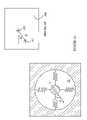
- FIGS. 1A-1Billustrate a pointing device 10 according to one embodiment of the present invention.
- FIG. 1Ais a top view of pointing device 10
- FIG. 1Bis a cross-sectional view of pointing device 10 through line 1 B- 1 B shown in FIG. 1A .
- Pointing device 10includes a puck 11 that moves over a surface 12 of a substrate 15 within a puck field of motion 19 in response to a lateral force applied to puck 11 .
- the forceis typically applied to puck 11 by a user's finger, finger tip, thumb, thumb tip or multiple fingers.
- Puck 11includes a pressure sensing mechanism that measures the vertical pressure applied to puck 11 .
- pointing device 10includes a sensing mechanism for determining the position of puck 11 on surface 12 .
- FIGS. 2A-2Billustrate the control of a cursor on a display 100 by the puck discussed above.
- the host apparatus of which pointing device 10 forms partThis change in position is used to move a cursor on the display by magnitude and direction that depends on the magnitude and direction of the motion of puck 11 while the vertical force was applied to puck 11 . That is, if the motion of puck 11 is characterized by a magnitude d and a direction defined by an angle ⁇ on the pointing device, the motion of cursor 101 is characterized by a magnitude D and a direction defined by angle ⁇ on display 100 .
- puck 11When the user releases puck 11 by removing the user's finger 16 , puck 11 is returned to its centered position by the springs shown at 13 that connect the puck to the side 14 of the puck field of motion. Since the user's finger is not applying a vertical force to puck 11 during its return, the change in position associated with that return motion is not reported to the host device. That is, cursor 101 remains at location 102 .
- Thisprovides a convenient “re-centering” capability, typically achieved on a mouse by lifting and replacing the mouse at the center of the field of motion. Re-centering is particularly necessary in laptop computers, hand-held devices and other miniature applications in which the field of motion is constrained.
- the pressure sensor in puck 11senses two predetermined pressure levels.
- the first levelis used to actuate the tracking of the cursor on the display as described above.
- the second levelis used to implement the “click” function associated with a conventional mouse.
- a mechanical clickcan also be engineered to provide tactile feedback for the “click” threshold.
- Puck 20includes a moveable element 21 that is suspended over a cavity 26 .
- the distance between element 21 and the bottom 25 of cavity 26changes in response to pressure applied to the top surface of element 21 .
- element 21is a deformable membrane suspended from spacers shown at 27 .
- the distance that element 21 has traveled from its resting positionis a measure of the force applied to element 21 . This distance can be sensed by any suitable mechanism.
- Each pressure switchis open when the force applied to element 21 is less than a predetermined value that is different for each switch.
- switch 23is engaged first and switches to the conducting state. This switch signals the host device that the pointing device has now been activated. At this point, the host device begins measuring the position of the pointing device and altering the position of the cursor on the display in response to those measurements.
- switch 24will also be closed.
- the state of this switchis independently monitored by the host device of which the pointing device forms part or a controller that is part of the pointing device itself.
- a button that can be actuated by the useris provided to signal the host device to take some particular note of the current position of the cursor on the display. Closing a switch by pushing this button is often referred to as “clicking” on the current cursor location.
- Switch 24may be used to provide this clicking function in pointing devices that utilize puck 20 .
- puck 20utilize separate switches for sensing the two force thresholds.
- the force thresholds for the activation of the cursor tracking and clicking functionscan be implemented using a single pressure sensing element that provides an analog measurement of the position of the surface of element 21 relative to the bottom 25 of the cavity.
- element 21may include an electrode that forms a capacitor with a corresponding element on the bottom of the cavity. As the distance between the surface of element 21 and the bottom 25 of the cavity changes, the capacitance of this capacitor also changes. The changes in capacitance can be measured by any of a number of conventional circuits and used to determine the distance between element 21 and the bottom of the cavity. In this case, two capacitance thresholds determine the two force thresholds described above.
- the above-described embodimentsutilized the elasticity of element 21 to provide a mechanism for converting the force applied to element 21 to a distance that can be measured.
- the cavity 26can be filled with a compressible medium such as foam rubber.
- a rigid moveable element suspended over a surface by a spring mechanismcan be utilized.
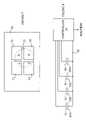
- FIG. 4is a cross-sectional view of another embodiment of a puck for use in a pointing device according to the present invention.
- Puck 30includes a cavity 36 having a rigid member 31 that is suspended over the bottom 35 of cavity 36 by springs. Exemplary springs are shown at 38 .
- member 31When no downward force is applied to member 31 , member 31 is held in place by a retaining ring shown at 37 .
- member 31moves toward the bottom of the cavity by a distance that depends on the applied force and the spring constants of springs 38 . Measuring the capacitance between electrodes 32 and 33 provides a measurement of the distance between member 31 and bottom 35 .
- Electrodes 32 , 33 , and 34form an electrical circuit that is equivalent to two capacitors connected in series with electrode 34 as the common electrode.
- Capacitor C 1represents the capacitance between electrodes 33 and 34
- capacitor C 2represents the capacitance between electrodes 32 and 34 .
- the total capacitance between electrodes 32 and 33depends on the distance between electrode 34 and electrodes 32 and 33 . This capacitance can be sensed with the aid of external electrical connections to electrodes 32 and 33 , which have been omitted from the drawing for the sake of simplicity.
- the capacitance measuring scheme described abovedoes not require an external electrical connection to electrode 34 , and hence, is inexpensive and simple in its implementation. However, other embodiments based on the measurement of the capacitance between electrode 34 and one or both of electrodes 32 and 33 can alternatively be utilized.
- FIG. 6is a cross-sectional view of another embodiment of a puck for use in the present invention.
- the springs shown at 38 in FIG. 4have been replaced by a conductive, compressible foam layer 46 whose resistivity depends on the compression of the foam.
- a conductive, compressible foam layer 46whose resistivity depends on the compression of the foam.
- FIG. 7is a top view of a portion of surface 12 shown in FIG. 1 over which the puck moves in one embodiment of the present invention.
- Surface 50includes four electrodes shown at 51 - 54 having terminals that are connected to an external circuit. To simplify the drawing, these terminals have been omitted.
- the puckhas a bottom surface that includes an electrode 55 that is shown in phantom in the drawing. Electrodes 51 - 55 are electrically isolated from one another. For example, electrode 55 can be covered with a layer of dielectric that provides the required insulation while still allowing electrode 55 to slide over the other electrodes.
- the electrodescan in fact be patterned on the back of the substrate whose surface is shown at 50 . This reduces the capacitance between the electrodes and the puck electrode, but can be practical for substrate thicknesses a few millimeters or less.
- the overlap between electrode 55 and each of electrodes 51 - 54depends on the position of the puck relative to electrodes 51 - 54 . Denote the overlaps between electrode 55 and electrodes 51 - 54 by A-D, respectively.
- FIG. 8is a schematic drawing of an equivalent circuit for electrodes 51 - 55 .
- the portion of electrode 55 that overlaps electrode 51forms a parallel plate capacitor having a capacitance that is proportional to overlap A.
- the portion of electrode 55 that overlaps electrode 52forms a parallel plate capacitor that has a capacitance that is proportional to overlap B, and so on. Since all of the capacitors share portions of electrode 55 , the equivalent circuit consists of four capacitors connected to a common electrode shown at 58 . This electrode is just electrode 55 .
- a controller 59which may be part of the pointing device or part of the host device of which the pointing device forms part.
- more than 4 electrodescan be placed on the substrate. Capacitance measurements between each of these electrodes and the puck can be used to determine the puck position as described above.
- the above-described embodiments of the position detectorhave an electrical connection to electrode 55 on the bottom of the puck.
- This connectioncan be eliminated in embodiments that measure the capacitative coupling between each pair of electrodes on surface 50 . That is, the capacitance between electrodes 51 and 52 is measured separately from the capacitance between electrodes 51 and 53 , and so on.
- the equivalent circuitis similar to that shown in FIG. 5 with C 1 being proportional to overlap A and C 2 being proportional to overlap C. Four measurements between adjacent electrodes provide information to solve for each of the four capacitances, and thereby determine the puck position.
- the electrode on the bottom of the puckis preferably circular in shape to reduce errors arising from the shape of the electrode.
- the restoring springsallow the puck to rotate somewhat. If the user's finger is not centered on the puck during the motion of the puck, the resultant torque can cause the puck to rotate slightly. If the puck electrode is circularly symmetric, such rotations will not alter the result of the position measurement. If, on the other hand, the puck electrode is not circularly symmetric, the overlap between the puck and the various electrodes will be different for different rotations, even though the center of the puck is at the same location in each case.
- FIG. 9Ais a top view of a portion of surface 12 shown in FIG. 1 over which the puck moves in another embodiment of the present invention.
- Surface 60includes a single resistive layer 61 having electrodes at its four corners as shown at 71 - 74 .
- the puck 62slides over this layer.
- Puck 62includes an electrode 63 that makes contact with a very small area of resistive layer 61 .
- the position of the puck in the puck field of motioncan also be ascertained using optical sensors such as those used in a conventional optical mouse.
- FIG. 9Bwhich illustrates such a sensing mechanism.
- the bottom surface 84 of puck 82includes a pattern or texture that is illuminated by an optical mouse sensor 83 located just below the surface 81 of the puck field of motion.
- optical mouse sensorsare known in the art, and hence, will not be discussed in detail here.
- optical mouse sensor 83has an illumination system that illuminates the bottom surface of puck 82 and an imaging sensor that forms an image of a portion of the illuminated surface. The imaging system compares successive images of the bottom surface to determine the distance and direction in which the puck moved between the images.
- the pressure sensing mechanismrequires two or three connections, depending on the particular embodiment being implemented.
- the position detectormay require an additional connection.
- the springs shown at 13are utilized for these connections in one preferred embodiment of the present invention.
- the springsare made from or coated with an electrically conducting material, and hence, each spring can provide an electrical connection to the puck.
- the above-described embodiment of the present inventionutilizes electrical connections made to the puck via the springs.
- Other methods for sensing the signals associated with the puck that do not require direct connections to the puckcan be utilized.
- Techniques for remote sensingare well known in the RF identification tag arts, and hence, will not be discussed in detail here.
- the values of capacitors and inductors in a remote devicecan be sensed by measuring the power the device absorbs from an RF signal.
- the pressure applied to the puckis sensed via a change in capacitance, as described above.
- the capacitor whose capacitance is being measuredcan be incorporated into a tank circuit whose resonance frequency is sensed by measuring the power absorbed by the puck as a function of frequency from an RF antennae located on the base of the pointing device.
- the embodiments of the present invention discussed aboveactivate the coupling between the cursor on the display and the puck when the pressure applied to the puck is greater than an activation threshold level, and release the coupling when the pressure falls below this threshold.
- an activation threshold levelWhen the pressure is released entirely, the puck is returned to its centered position by the springs discussed above.
- the distance through which the cursor is to movecan be greater than the maximum distance that can be moved by moving the puck from its resting position in the center of the puck field of motion to the boundary of the puck field of motion.
- the usercan make the required cursor movement in a manner analogous to that used with conventional mice, namely, recenter the puck by releasing the puck and then re-engaging the puck by placing a finger on the puck. Since the cursor was disengaged when the finger was removed prior to recentering of the puck, the user can resume moving the cursor on the display from the position on the display at which the user's finger was removed from the puck. While this approach provides a satisfactory solution for most cursor moves, there are occasions in which a very large move is needed. In such cases, accomplishing the move via a large number of smaller moves is not always satisfactory.
- the above-described embodimentsuse a meander spring to reposition the puck when the user releases the puck.
- the springs used to restore the puck positionprovide a restoring force that recenters the puck without requiring that the user apply a force that causes the user's hand to become fatigued.
- the forceshould not vary over the puck field of motion, since such variations can interfere with the precision with which the user can position the puck.
- embodiments that are designed for use in laptop computers, handheld devices and other miniature applicationsplace a premium on both the lateral size of the pointing device and the thickness of the pointing device. Hence, designs in which the springs increase the thickness or lateral dimensions of the pointing device are not preferred.
- the meander springs shown in FIG. 1prevent the puck from reaching all portions of the field of motion. This is particularly true if the puck motion is toward the attachment point of the spring on the periphery of the puck field of motion. Hence, to provide a device with a specified area in the field of motion, a somewhat larger lateral area is needed to accommodate the unusable space on the surface that is required for the springs in their compressed state. In addition, the force required for moving the puck is different for different areas of the puck field of view. Accordingly, the meander spring design shown in FIG. 1 is less than ideal.
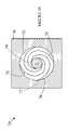
- FIG. 10is a top view of a pointing device 70 according to another embodiment of the present invention.
- Pointing device 70uses a spiral spring design that more nearly provides the ideal characteristics discussed above.
- Puck 75is attached to four spiral members shown at 71 - 74 .
- Each spiral memberhas one end attached to puck 75 and the other end attached to the fixed portion of the pointing device at a point on the periphery of the puck field of motion 76 .
- a typical attachment pointis shown at 77 .
- the optimal springis a spiral that turns through approximately 270-360 degrees. That is, a spring connected to the top of the puck at 12 o'clock as shown at 79 ends between 9 o'clock and 12 o'clock on the boundary of the puck field of motion as shown at 77 . While this is the preferred spring configuration, other spring configurations can be utilized. If shorter springs are used, the puck tends to rotate as it moves to the extremities of the puck field of motion. Such rotations can interfere with the position sensing mechanism in some designs. Springs longer than 360 degrees consume more of the available space and result in softer restoring forces.
- the puck design shown in FIG. 9Ahas a dead space adjacent to the boundary of the puck field of motion that is three times the width of a spring.
- Metal springs that are approximately 0.25 mm in widthperform adequately. Hence, an area that is less than 1 mm wide adjacent to the boundary of the puck field of motion is all that is wasted in such spiral spring based pointing devices.
- Plastic springs 0.75 mm wide and 1.5 mm thickare adequate for a puck that is 30 mm in diameter in a 60 mm diameter field of motion.
- k and k′are constants. While this curve is a good approximation for most of the spring's length, a curve that differs from this relationship at the two ends is advantageous.
- the two ends of the spiralare modified to make the ends nearly tangential to the points at which the spring attaches to the puck and the boundary of the puck field of motion. This modification allows the puck to more easily reach the extremities of the puck field of motion.
- R, ⁇polar coordinate system
- other forms of arcuate springscan be utilized; although such springs do not provide all of the advantages of the spiral members discussed above.
- the above-described embodiments of the present inventionutilize four springs for restoring the puck to its resting position.
- other numbers of springscan be utilized.
- one springcould be used; however, the spring would need to provide the return force in two directions, and hence, would no longer be isotropic, and would be much stiffer than the springs described above.
- more springscan be used to provide additional electrical connections to the puck.
- the springs in the above-described embodimentsideally return the puck to a resting position that is in the center of the field of motion. Such embodiments maximize the amount of motion that can be accommodated from the resting position.
- the puckneed not be returned exactly to the same starting position each time it is released.
- the puckneed not return to a resting position that is exactly in the center of the puck field of motion. So long as the puck returns to a position that is near enough to the center of the puck field of motion to allow the puck to be moved from that position to a new position in some desired direction, the present invention will provide an improvement over the meander spring design discussed above.
- the puckpreferably returns to its resting position with as few oscillations as possible.
- some form of oscillation dampingis preferably included.
- One method for damping oscillationsis to assure that the puck is pressed against the underlying surface as it returns to its resting position when released by the user. In this case, the friction between the puck and underlying surface provides the damping force. This can be accomplished by mounting the springs such that the springs apply a downward force on the puck.
- the attachment point for the end of the spring on the puckcan be located at a greater distance from the working surface than the attachment point for the other end of the spring.
- the springscan be deformed so that each spring exerts a downward force in addition to the restoring forces described above.
- FIG. 11is a cross-sectional view of yet another embodiment of a pointing device according to the present invention.
- Pointer 90includes a puck 91 that is similar to the pucks described above in that the puck includes a pressure sensing mechanism for defining a pressure threshold.
- Pointer 90also includes an electrode on the bottom of the puck for measuring the position of the puck relative to electrodes on the substrate 93 over which the puck moves.
- Exemplary substrate electrodesare shown at 94 and 95 .
- Puck 91also includes a magnet 96 that provides both the restoring force for returning the puck to its resting position when the puck is released by the user and the electrode structure for measuring the position of the puck.
- a corresponding magnet 97is included in substrate 93 .
- the poles of magnet 97are arranged opposite to those of magnet 96 .
- the magnetic fields of the magnetsare chosen such that the fields have their maximum values at the center of the magnets shown in FIG. 10 and decrease with distance from the center of the magnets. Hence, when the puck is released, it will be returned to a resting position in which the magnets are centered over one another.
- the magnetsprovide the downward damping force discussed above for reducing any oscillations of the puck about its resting position when the puck is released.
- the above-described embodiments of the present inventionuse the force exerted by the user's finger to trigger the coupling of the puck motion to the cursor motion on the display.
- other mechanismscan be utilized for signaling the cursor coupling.
- the presence of the user's finger on the puckcan be sensed capacitatively. Since such sensors are known to the art, they will not be discussed in detail here. It is sufficient to note that the presence of the user's finger measurably alters the capacitance of one or more electrodes on the puck.
- the user sensormay also be implemented without a separate force or capacitance sensor, but rather by software analysis of the puck x and y positions by the controller.
- the direction and acceleration of the puck motioncan be used to determine if the puck is being manipulated by the user or is just under the influence of the springs.
- embodiments of the present inventionutilize some form of restoring mechanism for returning the puck to its resting position when the user releases the pressure on the puck.
- the restoring mechanismis the user's finger can also be constructed.
- the userwould reduce the pressure on the puck to a level below the level at which the coupling of the puck to the cursor occurs.
- the usercan then move the puck to a new location manually without engaging the cursor on the display.
- the usercan then continue the cursor movement by once again pressing on the puck with sufficient pressure to activate the coupling of the puck and the cursor.
- the above-described embodiments of the present inventionrefer to the puck being returned to a predetermined resting point by the restoration mechanism when the user releases the puck.
- the predetermined embodimentsinclude some form of damping force to minimize the time needed for oscillations in the puck position to die out after the puck is released. As a result, the puck will not always return to precisely the starting point. However, such a precise return is not needed.
- Embodiments in which the puck returns generally to some predetermined starting areaalso perform satisfactorily. Any starting area that is sufficiently removed from the boundary of the puck field of motion will perform satisfactorily.
- the puck field of motioncan have other shapes.
- the puck field of motioncould be elliptical or rectangular. In these cases, the optimal spring shapes will be different than those described above.
Landscapes
- Engineering & Computer Science (AREA)
- General Engineering & Computer Science (AREA)
- Theoretical Computer Science (AREA)
- Human Computer Interaction (AREA)
- Physics & Mathematics (AREA)
- General Physics & Mathematics (AREA)
- Position Input By Displaying (AREA)
Abstract
Description
Claims (14)
Priority Applications (6)
| Application Number | Priority Date | Filing Date | Title |
|---|---|---|---|
| US10/723,957US7429976B2 (en) | 2003-11-24 | 2003-11-24 | Compact pointing device |
| JP2006541261AJP4909080B2 (en) | 2003-11-24 | 2004-11-10 | Small pointing device |
| EP04800990AEP1687699A2 (en) | 2003-11-24 | 2004-11-10 | Compact pointing device |
| PCT/US2004/037675WO2005055032A2 (en) | 2003-11-24 | 2004-11-10 | Compact pointing device |
| CNB2004800347933ACN100480961C (en) | 2003-11-24 | 2004-11-10 | Compact pointing device |
| KR1020067010025AKR101097603B1 (en) | 2003-11-24 | 2006-05-23 | Pointing device |
Applications Claiming Priority (1)
| Application Number | Priority Date | Filing Date | Title |
|---|---|---|---|
| US10/723,957US7429976B2 (en) | 2003-11-24 | 2003-11-24 | Compact pointing device |
Publications (2)
| Publication Number | Publication Date |
|---|---|
| US20050110755A1 US20050110755A1 (en) | 2005-05-26 |
| US7429976B2true US7429976B2 (en) | 2008-09-30 |
Family
ID=34592441
Family Applications (1)
| Application Number | Title | Priority Date | Filing Date |
|---|---|---|---|
| US10/723,957Expired - Fee RelatedUS7429976B2 (en) | 2003-11-24 | 2003-11-24 | Compact pointing device |
Country Status (6)
| Country | Link |
|---|---|
| US (1) | US7429976B2 (en) |
| EP (1) | EP1687699A2 (en) |
| JP (1) | JP4909080B2 (en) |
| KR (1) | KR101097603B1 (en) |
| CN (1) | CN100480961C (en) |
| WO (1) | WO2005055032A2 (en) |
Cited By (13)
| Publication number | Priority date | Publication date | Assignee | Title |
|---|---|---|---|---|
| US20060232551A1 (en)* | 2005-04-18 | 2006-10-19 | Farid Matta | Electronic device and method for simplifying text entry using a soft keyboard |
| US20080012029A1 (en)* | 2004-08-13 | 2008-01-17 | Schranz Paul S | Light Emitting and Image Sensing Device and Apparatus |
| US20080018596A1 (en)* | 2006-07-18 | 2008-01-24 | Jonah Harley | Capacitive sensing in displacement type pointing devices |
| US20080243333A1 (en)* | 2007-03-30 | 2008-10-02 | Fujitsu Component Limited | Device operating system, controller, and control program product |
| US20080249668A1 (en)* | 2007-04-09 | 2008-10-09 | C/O Kabushiki Kaisha Tokai Rika Denki Seisakusho | In-vehicle equipment control device |
| US20090009194A1 (en)* | 2007-07-03 | 2009-01-08 | Cypress Semiconductor Corporation | Normalizing capacitive sensor array signals |
| US20090057124A1 (en)* | 2007-08-27 | 2009-03-05 | Timothy James Orsley | Control and Data Entry Apparatus |
| US20090135136A1 (en)* | 2007-11-23 | 2009-05-28 | Timothy James Orsley | Magnetic Re-Centering Mechanism for a Capacitive Input Device |
| US20100177043A1 (en)* | 2009-01-10 | 2010-07-15 | Tzu-Hung Chen | Flip-operation mouse device |
| US20110006928A1 (en)* | 2008-04-28 | 2011-01-13 | Takeharu Kitagawa | Composite switch and portable device with same |
| US20120026087A1 (en)* | 2010-07-28 | 2012-02-02 | Lian-Tien Ke | Movable operation plate module and electronic device with the same |
| US9007322B1 (en) | 2008-07-23 | 2015-04-14 | Cypress Semiconductor Corporation | Compensation of signal values for a touch sensor |
| US9948297B2 (en) | 2010-04-14 | 2018-04-17 | Frederick Johannes Bruwer | Pressure dependent capacitive sensing circuit switch construction |
Families Citing this family (36)
| Publication number | Priority date | Publication date | Assignee | Title |
|---|---|---|---|---|
| US7570247B2 (en)* | 2003-11-24 | 2009-08-04 | Avago Technologies Ecbu Ip (Singapore) Pte. Ltd. | Modular assembly for a self-indexing computer pointing device |
| US7429976B2 (en) | 2003-11-24 | 2008-09-30 | Avago Technologies Ecbu Ip (Singapore) Pte. Ltd. | Compact pointing device |
| US7304637B2 (en)* | 2004-08-30 | 2007-12-04 | Avago Technologies Ecbuip (Singapore) Pte Ltd | Puck-based input device with rotation detection |
| US7349822B2 (en)* | 2004-12-23 | 2008-03-25 | Avago Technologies Ecbu Ip Pte Ltd. | Slide pad system and method |
| US7978173B2 (en)* | 2005-01-14 | 2011-07-12 | Avago Technologies Ecbu Ip (Singapore) Pte. Ltd. | Pointing device including a moveable puck with mechanical detents |
| US7586480B2 (en)* | 2005-02-28 | 2009-09-08 | Avago Technologies Ecbu Ip (Singapore) Pte. Ltd. | Hybrid pointing device |
| US20060271886A1 (en)* | 2005-05-25 | 2006-11-30 | Wenstrand John S | Character entry system and method for electronic devices |
| US20060290665A1 (en)* | 2005-06-24 | 2006-12-28 | Farid Matta | Slide pad notebook pointing device with sealed spring system |
| JP2007004705A (en)* | 2005-06-27 | 2007-01-11 | Mitsumi Electric Co Ltd | Joy stick device |
| US7161136B1 (en) | 2005-07-06 | 2007-01-09 | Avago Technologies Ecbu Ip (Singapore) Pte. Ltd. | Light modulating input device for capturing user control inputs |
| US7701440B2 (en)* | 2005-12-19 | 2010-04-20 | Avago Technologies Ecbu Ip (Singapore) Pte. Ltd. | Pointing device adapted for small handheld devices having two display modes |
| US20070159456A1 (en)* | 2006-01-10 | 2007-07-12 | Unkrich Mark A | Navigation system |
| GB2445719B (en)* | 2006-01-26 | 2011-02-16 | Avago Technologies Us Inc | A pointing device including a moveable puck with mechanical detents |
| US7733327B2 (en)* | 2006-04-19 | 2010-06-08 | Avago Technologies Ecbu Ip (Singapore) Pte. Ltd. | Re-centering mechanism for an input device |
| US20070247446A1 (en)* | 2006-04-25 | 2007-10-25 | Timothy James Orsley | Linear positioning input device |
| US20080024441A1 (en)* | 2006-07-25 | 2008-01-31 | Jonah Harley | Displacement type pointing device and method |
| US20080042974A1 (en)* | 2006-08-17 | 2008-02-21 | Sachs Todd S | System and method for determining cursor speed in a puck-based pointing device |
| US8188970B2 (en)* | 2006-08-17 | 2012-05-29 | Avago Technologies Ecbu Ip (Singapore) Pte. Ltd. | System and method for automatic re-calulation and monitoring of thresholds in a puck-based pointing device |
| US9141230B2 (en)* | 2006-08-30 | 2015-09-22 | Avaoo Technologies General IP (Singapore) Pte. Ltd. | Optical sensing in displacement type input apparatus and methods |
| US7902475B2 (en)* | 2006-09-11 | 2011-03-08 | Apple Inc. | Flushness shims |
| US7639234B2 (en)* | 2007-01-04 | 2009-12-29 | Avago Technologies Ecbu Ip (Singapore) Pte. Ltd. | Capacitive sensing and absolute position mapping in displacement type pointing devices |
| JP2010521755A (en)* | 2007-03-17 | 2010-06-24 | プレー ゲーエムベーハー | Automotive control elements |
| KR101204794B1 (en)* | 2007-06-05 | 2012-11-26 | 삼성전자주식회사 | Display Apparatus and Method for location recognition |
| US20090058802A1 (en)* | 2007-08-27 | 2009-03-05 | Avago Technologies Ecbu Ip (Singapore) Pte. Ltd. | Input device |
| KR100893755B1 (en)* | 2007-10-05 | 2009-04-20 | 주식회사 이노칩테크놀로지 | Pointing device and electronic device having the same |
| US20090135157A1 (en)* | 2007-11-27 | 2009-05-28 | Avago Technologies Ecbu Ip (Singapore) Pte. Ltd. | Capacitive Sensing Input Device with Reduced Sensitivity to Humidity and Condensation |
| KR100931069B1 (en)* | 2008-02-15 | 2009-12-10 | 주식회사 이노칩테크놀로지 | Pointing device and electronic device having the same |
| KR100909546B1 (en) | 2008-03-04 | 2009-07-27 | 지송학 | Pointing device |
| TWI414965B (en)* | 2008-08-29 | 2013-11-11 | Hon Hai Prec Ind Co Ltd | Keyboard |
| US9740340B1 (en)* | 2009-07-31 | 2017-08-22 | Amazon Technologies, Inc. | Visually consistent arrays including conductive mesh |
| CN102375586B (en)* | 2010-08-19 | 2014-12-03 | 苏州敏芯微电子技术有限公司 | Control system for identifying direction and force |
| US8547333B2 (en)* | 2011-06-22 | 2013-10-01 | Blackberry Limited | Optical navigation device with haptic feedback |
| CN102955641B (en)* | 2011-08-22 | 2016-01-20 | 幻音科技(深圳)有限公司 | input method, system and mouse pad |
| US20140253503A1 (en)* | 2013-03-05 | 2014-09-11 | Bang & Olufsen A/S | Touch system configured on metal surface with x-y and force detection |
| HUP1500189A2 (en)* | 2015-04-24 | 2016-10-28 | Geza Balint | Process and recording device for recording data electronically |
| US11670467B2 (en) | 2021-04-22 | 2023-06-06 | Dell Products, Lp | Spring-back force adjustable input/output device for an information handling system |
Citations (46)
| Publication number | Priority date | Publication date | Assignee | Title |
|---|---|---|---|---|
| US3987685A (en) | 1974-12-16 | 1976-10-26 | Xerox Corporation | Cursor position device |
| US4670743A (en)* | 1985-01-31 | 1987-06-02 | General Instrument Corporation | Keyboard cursor controller |
| US4719455A (en) | 1986-01-24 | 1988-01-12 | Louis William M | Integrating pointing device |
| US5056146A (en)* | 1987-09-29 | 1991-10-08 | Kabushiki Kaisha Toshiba | Three-dimensional labeling apparatus for two-dimensional slice image information |
| US5086296A (en)* | 1987-12-02 | 1992-02-04 | U.S. Philips Corporation | Signal generating device |
| GB2247938A (en) | 1990-08-18 | 1992-03-18 | David Roger Sherriff | Capacitative puck |
| US5252952A (en) | 1990-10-26 | 1993-10-12 | The Cherry Corporation | Cursor device with zero-point resetting |
| US5504502A (en)* | 1990-09-18 | 1996-04-02 | Fujitsu Limited | Pointing control device for moving a cursor on a display on a computer |
| US5659334A (en) | 1993-12-15 | 1997-08-19 | Interlink Electronics, Inc. | Force-sensing pointing device |
| US5703356A (en) | 1992-10-05 | 1997-12-30 | Logitech, Inc. | Pointing device utilizing a photodetector array |
| US5704037A (en)* | 1996-03-20 | 1997-12-30 | Chen; Mei Yun | Cursor positioning device for computer system |
| US5739821A (en) | 1997-01-30 | 1998-04-14 | Primax Electronics Ltd. | Method for pointing a window frame or an icon of a window interface |
| US5808603A (en)* | 1997-02-06 | 1998-09-15 | Chen; Mei Yun | Computer input device |
| US5815139A (en)* | 1996-05-01 | 1998-09-29 | Smk Corporation | Relative manipulated variable input device |
| US5889507A (en) | 1990-07-24 | 1999-03-30 | Incontrol Solutions, Inc. | Miniature isometric joystick |
| US5914465A (en)* | 1992-06-08 | 1999-06-22 | Synaptics, Inc. | Object position detector |
| US5956016A (en)* | 1996-03-19 | 1999-09-21 | Bayerische Motoren Werke Aktiengesellschaft | Operating device for menu-controlled functions of a vehicle |
| US6115030A (en) | 1997-12-18 | 2000-09-05 | International Business Machines Corporation | Trackpoint device |
| US6198473B1 (en)* | 1998-10-06 | 2001-03-06 | Brad A. Armstrong | Computer mouse with enhance control button (s) |
| US6256012B1 (en)* | 1998-08-25 | 2001-07-03 | Varatouch Technology Incorporated | Uninterrupted curved disc pointing device |
| US6288707B1 (en) | 1996-07-29 | 2001-09-11 | Harald Philipp | Capacitive position sensor |
| US6292174B1 (en) | 1997-08-23 | 2001-09-18 | Immersion Corporation | Enhanced cursor control using limited-workspace force feedback devices |
| US6326948B1 (en)* | 1997-01-20 | 2001-12-04 | Sharp Kabushiki Kaisha | Input device |
| US6492911B1 (en) | 1999-04-19 | 2002-12-10 | Netzer Motion Sensors Ltd. | Capacitive displacement encoder |
| US20030048262A1 (en) | 1999-05-24 | 2003-03-13 | Charles Wu | Method and apparatus for navigation, text input and phone dialing |
| US20030076301A1 (en) | 2001-10-22 | 2003-04-24 | Apple Computer, Inc. | Method and apparatus for accelerated scrolling |
| US20030095096A1 (en) | 2001-10-22 | 2003-05-22 | Apple Computer, Inc. | Method and apparatus for use of rotational user inputs |
| US6667733B2 (en) | 2000-01-21 | 2003-12-23 | Hosiden Corporation | Pointing device |
| US20040108993A1 (en) | 2002-11-25 | 2004-06-10 | Nec Corporation | Pointing device and electronic apparatus provided with the pointing device |
| US6753848B2 (en) | 2000-12-28 | 2004-06-22 | Hosiden Corporation | Pointing device |
| US6762748B2 (en)* | 2000-12-27 | 2004-07-13 | Nokia Corporation | Compact low profile magnetic input device |
| US6816154B2 (en) | 2001-05-30 | 2004-11-09 | Palmone, Inc. | Optical sensor based user interface for a portable electronic device |
| US20050052429A1 (en) | 2003-08-21 | 2005-03-10 | Harald Philipp | Capacitive position sensor |
| US20050052426A1 (en)* | 2003-09-08 | 2005-03-10 | Hagermoser E. Scott | Vehicle touch input device and methods of making same |
| US20050052425A1 (en) | 2003-08-18 | 2005-03-10 | Zadesky Stephen Paul | Movable touch pad with added functionality |
| US20050062732A1 (en) | 2001-03-30 | 2005-03-24 | Microsoft Corporation | Capacitance touch slider |
| US20050110755A1 (en) | 2003-11-24 | 2005-05-26 | Jonah Harley | Compact pointing device |
| US6961052B1 (en) | 2003-03-17 | 2005-11-01 | Cisco Technology, Inc. | Methods and apparatus for providing multi-directional navigation control |
| US20060001657A1 (en) | 2004-07-02 | 2006-01-05 | Logitech Europe S.A. | Scrolling device |
| US20060038783A1 (en) | 1999-11-04 | 2006-02-23 | Shaw Scott J | Capacitive mouse |
| WO2006031332A2 (en) | 2004-08-30 | 2006-03-23 | Agilent Technologies, Inc. | Puck-based input device with rotation detection |
| US7042441B2 (en) | 2002-06-28 | 2006-05-09 | Microsoft Corporation | Input device including a scroll wheel assembly for manipulating an image in multiple directions |
| US7046230B2 (en) | 2001-10-22 | 2006-05-16 | Apple Computer, Inc. | Touch pad handheld device |
| US20060176270A1 (en) | 2005-02-04 | 2006-08-10 | Sachs Todd S | One dimensional and three dimensional extensions of the slide pad |
| US7123028B2 (en) | 2001-08-10 | 2006-10-17 | Wacoh Corporation | Force detector |
| US7158115B2 (en) | 2003-11-24 | 2007-01-02 | Avago Technologies Ecbu Ip (Singapore) Pte. Ltd. | Spring system for re-centering a movable object |
Family Cites Families (2)
| Publication number | Priority date | Publication date | Assignee | Title |
|---|---|---|---|---|
| EP1433123A1 (en) | 2001-09-04 | 2004-06-30 | Ziad Badarneh | Operating device for controlling functions in electronic equipment |
| JP2003084916A (en)* | 2001-09-11 | 2003-03-20 | Alps Electric Co Ltd | Coordinate input device |
- 2003
- 2003-11-24USUS10/723,957patent/US7429976B2/ennot_activeExpired - Fee Related
- 2004
- 2004-11-10JPJP2006541261Apatent/JP4909080B2/ennot_activeExpired - Fee Related
- 2004-11-10EPEP04800990Apatent/EP1687699A2/ennot_activeWithdrawn
- 2004-11-10WOPCT/US2004/037675patent/WO2005055032A2/ennot_activeApplication Discontinuation
- 2004-11-10CNCNB2004800347933Apatent/CN100480961C/ennot_activeExpired - Fee Related
- 2006
- 2006-05-23KRKR1020067010025Apatent/KR101097603B1/ennot_activeExpired - Fee Related
Patent Citations (47)
| Publication number | Priority date | Publication date | Assignee | Title |
|---|---|---|---|---|
| US3987685A (en) | 1974-12-16 | 1976-10-26 | Xerox Corporation | Cursor position device |
| US4670743A (en)* | 1985-01-31 | 1987-06-02 | General Instrument Corporation | Keyboard cursor controller |
| US4719455A (en) | 1986-01-24 | 1988-01-12 | Louis William M | Integrating pointing device |
| US5056146A (en)* | 1987-09-29 | 1991-10-08 | Kabushiki Kaisha Toshiba | Three-dimensional labeling apparatus for two-dimensional slice image information |
| US5086296A (en)* | 1987-12-02 | 1992-02-04 | U.S. Philips Corporation | Signal generating device |
| US5889507A (en) | 1990-07-24 | 1999-03-30 | Incontrol Solutions, Inc. | Miniature isometric joystick |
| GB2247938A (en) | 1990-08-18 | 1992-03-18 | David Roger Sherriff | Capacitative puck |
| US5504502A (en)* | 1990-09-18 | 1996-04-02 | Fujitsu Limited | Pointing control device for moving a cursor on a display on a computer |
| US5252952A (en) | 1990-10-26 | 1993-10-12 | The Cherry Corporation | Cursor device with zero-point resetting |
| US5914465A (en)* | 1992-06-08 | 1999-06-22 | Synaptics, Inc. | Object position detector |
| US5703356A (en) | 1992-10-05 | 1997-12-30 | Logitech, Inc. | Pointing device utilizing a photodetector array |
| US5659334A (en) | 1993-12-15 | 1997-08-19 | Interlink Electronics, Inc. | Force-sensing pointing device |
| US5956016A (en)* | 1996-03-19 | 1999-09-21 | Bayerische Motoren Werke Aktiengesellschaft | Operating device for menu-controlled functions of a vehicle |
| US5704037A (en)* | 1996-03-20 | 1997-12-30 | Chen; Mei Yun | Cursor positioning device for computer system |
| US5815139A (en)* | 1996-05-01 | 1998-09-29 | Smk Corporation | Relative manipulated variable input device |
| US6288707B1 (en) | 1996-07-29 | 2001-09-11 | Harald Philipp | Capacitive position sensor |
| US6326948B1 (en)* | 1997-01-20 | 2001-12-04 | Sharp Kabushiki Kaisha | Input device |
| US5739821A (en) | 1997-01-30 | 1998-04-14 | Primax Electronics Ltd. | Method for pointing a window frame or an icon of a window interface |
| US5808603A (en)* | 1997-02-06 | 1998-09-15 | Chen; Mei Yun | Computer input device |
| US6292174B1 (en) | 1997-08-23 | 2001-09-18 | Immersion Corporation | Enhanced cursor control using limited-workspace force feedback devices |
| US6115030A (en) | 1997-12-18 | 2000-09-05 | International Business Machines Corporation | Trackpoint device |
| US6256012B1 (en)* | 1998-08-25 | 2001-07-03 | Varatouch Technology Incorporated | Uninterrupted curved disc pointing device |
| US6198473B1 (en)* | 1998-10-06 | 2001-03-06 | Brad A. Armstrong | Computer mouse with enhance control button (s) |
| US6492911B1 (en) | 1999-04-19 | 2002-12-10 | Netzer Motion Sensors Ltd. | Capacitive displacement encoder |
| US20030048262A1 (en) | 1999-05-24 | 2003-03-13 | Charles Wu | Method and apparatus for navigation, text input and phone dialing |
| US20060038783A1 (en) | 1999-11-04 | 2006-02-23 | Shaw Scott J | Capacitive mouse |
| US6667733B2 (en) | 2000-01-21 | 2003-12-23 | Hosiden Corporation | Pointing device |
| US6762748B2 (en)* | 2000-12-27 | 2004-07-13 | Nokia Corporation | Compact low profile magnetic input device |
| US6753848B2 (en) | 2000-12-28 | 2004-06-22 | Hosiden Corporation | Pointing device |
| US20050062732A1 (en) | 2001-03-30 | 2005-03-24 | Microsoft Corporation | Capacitance touch slider |
| US6816154B2 (en) | 2001-05-30 | 2004-11-09 | Palmone, Inc. | Optical sensor based user interface for a portable electronic device |
| US7123028B2 (en) | 2001-08-10 | 2006-10-17 | Wacoh Corporation | Force detector |
| US20030076301A1 (en) | 2001-10-22 | 2003-04-24 | Apple Computer, Inc. | Method and apparatus for accelerated scrolling |
| US20030095096A1 (en) | 2001-10-22 | 2003-05-22 | Apple Computer, Inc. | Method and apparatus for use of rotational user inputs |
| US7046230B2 (en) | 2001-10-22 | 2006-05-16 | Apple Computer, Inc. | Touch pad handheld device |
| US7042441B2 (en) | 2002-06-28 | 2006-05-09 | Microsoft Corporation | Input device including a scroll wheel assembly for manipulating an image in multiple directions |
| US20040108993A1 (en) | 2002-11-25 | 2004-06-10 | Nec Corporation | Pointing device and electronic apparatus provided with the pointing device |
| US6961052B1 (en) | 2003-03-17 | 2005-11-01 | Cisco Technology, Inc. | Methods and apparatus for providing multi-directional navigation control |
| US20050052425A1 (en) | 2003-08-18 | 2005-03-10 | Zadesky Stephen Paul | Movable touch pad with added functionality |
| US20070052691A1 (en) | 2003-08-18 | 2007-03-08 | Apple Computer, Inc. | Movable touch pad with added functionality |
| US20050052429A1 (en) | 2003-08-21 | 2005-03-10 | Harald Philipp | Capacitive position sensor |
| US20050052426A1 (en)* | 2003-09-08 | 2005-03-10 | Hagermoser E. Scott | Vehicle touch input device and methods of making same |
| US20050110755A1 (en) | 2003-11-24 | 2005-05-26 | Jonah Harley | Compact pointing device |
| US7158115B2 (en) | 2003-11-24 | 2007-01-02 | Avago Technologies Ecbu Ip (Singapore) Pte. Ltd. | Spring system for re-centering a movable object |
| US20060001657A1 (en) | 2004-07-02 | 2006-01-05 | Logitech Europe S.A. | Scrolling device |
| WO2006031332A2 (en) | 2004-08-30 | 2006-03-23 | Agilent Technologies, Inc. | Puck-based input device with rotation detection |
| US20060176270A1 (en) | 2005-02-04 | 2006-08-10 | Sachs Todd S | One dimensional and three dimensional extensions of the slide pad |
Non-Patent Citations (11)
| Title |
|---|
| "3M Double Coated tapes", 9731 931RW Technical Data. |
| "Motorola SLVR", www.motorola.com/motoinfo/product/details.jsp,(unknown). |
| ARS Technica, iPod nano, http://arstechnica.com/reviews/ardware/nano.ars/4,, (1998). |
| Avago Technologies, "AMRI-2000 Data Sheet". |
| Avago Technologies, "AMRI-2000-P000 Data Sheet". |
| Panasonic, "Panasonic Tactile Sheet Type ESP". |
| U.S. Appl. No. 10/723,957, filed Nov. 24, 2003, Harley. |
| U.S. Appl. No. 11/407,274, filed Apr. 19, 2006, Orsley. |
| U.S. Appl. No. 11/606,556, filed Nov. 30, 2007, Harley et al. |
| U.S. Appl. No. 11/923,653, filed Oct. 25, 2007, Orsley. |
| U.S. Appl. No. 60/794,723, filed Apr. 25, 2006, Harley. |
Cited By (23)
| Publication number | Priority date | Publication date | Assignee | Title |
|---|---|---|---|---|
| US20090166643A1 (en)* | 2004-08-13 | 2009-07-02 | Paul Steven Schranz | Light emitting and image sensing device and apparatus |
| US20080012029A1 (en)* | 2004-08-13 | 2008-01-17 | Schranz Paul S | Light Emitting and Image Sensing Device and Apparatus |
| US7521719B2 (en) | 2004-08-13 | 2009-04-21 | Paul Steven Schranz | Light emitting and image sensing device and apparatus |
| US20060232551A1 (en)* | 2005-04-18 | 2006-10-19 | Farid Matta | Electronic device and method for simplifying text entry using a soft keyboard |
| US7616191B2 (en) | 2005-04-18 | 2009-11-10 | Avago Technologies Ecbu Ip (Singapore) Pte. Ltd. | Electronic device and method for simplifying text entry using a soft keyboard |
| US20080018596A1 (en)* | 2006-07-18 | 2008-01-24 | Jonah Harley | Capacitive sensing in displacement type pointing devices |
| US20080243333A1 (en)* | 2007-03-30 | 2008-10-02 | Fujitsu Component Limited | Device operating system, controller, and control program product |
| US20080249668A1 (en)* | 2007-04-09 | 2008-10-09 | C/O Kabushiki Kaisha Tokai Rika Denki Seisakusho | In-vehicle equipment control device |
| US8229603B2 (en)* | 2007-04-09 | 2012-07-24 | Kabushiki Kaisha Tokai Rika Denki Seisakusho | In-vehicle equipment control device |
| US20090009194A1 (en)* | 2007-07-03 | 2009-01-08 | Cypress Semiconductor Corporation | Normalizing capacitive sensor array signals |
| USRE46317E1 (en) | 2007-07-03 | 2017-02-21 | Monterey Research, Llc | Normalizing capacitive sensor array signals |
| US8315832B1 (en) | 2007-07-03 | 2012-11-20 | Cypress Semiconductor Corporation | Normalizing capacitive sensor array signals |
| US8086417B2 (en)* | 2007-07-03 | 2011-12-27 | Cypress Semiconductor Corporation | Normalizing capacitive sensor array signals |
| US20090057124A1 (en)* | 2007-08-27 | 2009-03-05 | Timothy James Orsley | Control and Data Entry Apparatus |
| US8232963B2 (en) | 2007-08-27 | 2012-07-31 | Avago Technologies Ecbu Ip (Singapore) Pte. Ltd. | Control and data entry apparatus |
| US7978175B2 (en)* | 2007-11-23 | 2011-07-12 | Avago Technologies Ecbu Ip (Singapore) Pte. Ltd. | Magnetic re-centering mechanism for a capacitive input device |
| US20090135136A1 (en)* | 2007-11-23 | 2009-05-28 | Timothy James Orsley | Magnetic Re-Centering Mechanism for a Capacitive Input Device |
| US20110006928A1 (en)* | 2008-04-28 | 2011-01-13 | Takeharu Kitagawa | Composite switch and portable device with same |
| US9082565B2 (en)* | 2008-04-28 | 2015-07-14 | Lenovo Innovations Limited (Hong Kong) | Composite switch and portable device with same |
| US9007322B1 (en) | 2008-07-23 | 2015-04-14 | Cypress Semiconductor Corporation | Compensation of signal values for a touch sensor |
| US20100177043A1 (en)* | 2009-01-10 | 2010-07-15 | Tzu-Hung Chen | Flip-operation mouse device |
| US9948297B2 (en) | 2010-04-14 | 2018-04-17 | Frederick Johannes Bruwer | Pressure dependent capacitive sensing circuit switch construction |
| US20120026087A1 (en)* | 2010-07-28 | 2012-02-02 | Lian-Tien Ke | Movable operation plate module and electronic device with the same |
Also Published As
| Publication number | Publication date |
|---|---|
| EP1687699A2 (en) | 2006-08-09 |
| KR101097603B1 (en) | 2011-12-22 |
| WO2005055032A2 (en) | 2005-06-16 |
| JP2007512627A (en) | 2007-05-17 |
| CN100480961C (en) | 2009-04-22 |
| WO2005055032A3 (en) | 2005-09-15 |
| CN1886714A (en) | 2006-12-27 |
| JP4909080B2 (en) | 2012-04-04 |
| KR20060117954A (en) | 2006-11-17 |
| US20050110755A1 (en) | 2005-05-26 |
Similar Documents
| Publication | Publication Date | Title |
|---|---|---|
| US7429976B2 (en) | Compact pointing device | |
| US7982714B2 (en) | Puck-based input device with rotation detection | |
| US7701440B2 (en) | Pointing device adapted for small handheld devices having two display modes | |
| CN100514267C (en) | Pointing device and method of inputting data into a device having a display screen | |
| US7570247B2 (en) | Modular assembly for a self-indexing computer pointing device | |
| US20090033620A1 (en) | Portable Electronic Device and Touch Pad Device for the Same | |
| KR20060017512A (en) | Multifunction floating button | |
| KR101107954B1 (en) | Pointing device with extended travel | |
| US8471811B2 (en) | Puck-based pointing device that provides multiple buttons | |
| US7978173B2 (en) | Pointing device including a moveable puck with mechanical detents | |
| US20060290665A1 (en) | Slide pad notebook pointing device with sealed spring system | |
| US6788287B2 (en) | Dual-dimension cursor control pad | |
| US20060125781A1 (en) | Sliding structure location on a pointing device corrected for non-linearity of measured differential | |
| KR100932357B1 (en) | Pointing device and item selection method on display using same |
Legal Events
| Date | Code | Title | Description |
|---|---|---|---|
| AS | Assignment | Owner name:AGILENT TECHNOLOGIES, INC., COLORADO Free format text:ASSIGNMENT OF ASSIGNORS INTEREST;ASSIGNORS:HARLEY, JONAH;MATTA, FARID;HOEN, STORRS;REEL/FRAME:014563/0672;SIGNING DATES FROM 20031119 TO 20031120 | |
| AS | Assignment | Owner name:AVAGO TECHNOLOGIES GENERAL IP PTE. LTD.,SINGAPORE Free format text:ASSIGNMENT OF ASSIGNORS INTEREST;ASSIGNOR:AGILENT TECHNOLOGIES, INC.;REEL/FRAME:017206/0666 Effective date:20051201 Owner name:AVAGO TECHNOLOGIES GENERAL IP PTE. LTD., SINGAPORE Free format text:ASSIGNMENT OF ASSIGNORS INTEREST;ASSIGNOR:AGILENT TECHNOLOGIES, INC.;REEL/FRAME:017206/0666 Effective date:20051201 | |
| AS | Assignment | Owner name:AVAGO TECHNOLOGIES ECBU IP (SINGAPORE) PTE. LTD., SINGAPORE Free format text:ASSIGNMENT OF ASSIGNORS INTEREST;ASSIGNOR:AVAGO TECHNOLOGIES GENERAL IP (SINGAPORE) PTE. LTD.;REEL/FRAME:017675/0518 Effective date:20060127 Owner name:AVAGO TECHNOLOGIES ECBU IP (SINGAPORE) PTE. LTD.,S Free format text:ASSIGNMENT OF ASSIGNORS INTEREST;ASSIGNOR:AVAGO TECHNOLOGIES GENERAL IP (SINGAPORE) PTE. LTD.;REEL/FRAME:017675/0518 Effective date:20060127 Owner name:AVAGO TECHNOLOGIES ECBU IP (SINGAPORE) PTE. LTD., Free format text:ASSIGNMENT OF ASSIGNORS INTEREST;ASSIGNOR:AVAGO TECHNOLOGIES GENERAL IP (SINGAPORE) PTE. LTD.;REEL/FRAME:017675/0518 Effective date:20060127 | |
| FPAY | Fee payment | Year of fee payment:4 | |
| AS | Assignment | Owner name:AVAGO TECHNOLOGIES GENERAL IP (SINGAPORE) PTE. LTD Free format text:MERGER;ASSIGNOR:AVAGO TECHNOLOGIES ECBU IP (SINGAPORE) PTE. LTD.;REEL/FRAME:030251/0018 Effective date:20121030 | |
| AS | Assignment | Owner name:AVAGO TECHNOLOGIES GENERAL IP (SINGAPORE) PTE. LTD Free format text:MERGER;ASSIGNOR:AVAGO TECHNOLOGIES ECBU IP (SINGAPORE) PTE. LTD.;REEL/FRAME:030369/0528 Effective date:20121030 | |
| AS | Assignment | Owner name:AVAGO TECHNOLOGIES GENERAL IP (SINGAPORE) PTE. LTD Free format text:CORRECTIVE ASSIGNMENT TO CORRECT THE ASSIGNEE NAME PREVIOUSLY RECORDED AT REEL: 017206 FRAME: 0666. ASSIGNOR(S) HEREBY CONFIRMS THE ASSIGNMENT;ASSIGNOR:AGILENT TECHNOLOGIES, INC.;REEL/FRAME:038632/0662 Effective date:20051201 | |
| REMI | Maintenance fee reminder mailed | ||
| LAPS | Lapse for failure to pay maintenance fees | ||
| STCH | Information on status: patent discontinuation | Free format text:PATENT EXPIRED DUE TO NONPAYMENT OF MAINTENANCE FEES UNDER 37 CFR 1.362 | |
| FP | Lapsed due to failure to pay maintenance fee | Effective date:20160930 |