US7428819B2 - Method for the operation of a compressor of a gas turbine with evaporative cooling of the compressor induction air - Google Patents
Method for the operation of a compressor of a gas turbine with evaporative cooling of the compressor induction airDownload PDFInfo
- Publication number
- US7428819B2 US7428819B2US11/562,482US56248206AUS7428819B2US 7428819 B2US7428819 B2US 7428819B2US 56248206 AUS56248206 AUS 56248206AUS 7428819 B2US7428819 B2US 7428819B2
- Authority
- US
- United States
- Prior art keywords
- compressor
- evaporative cooling
- environmental conditions
- temperature
- map
- Prior art date
- Legal status (The legal status is an assumption and is not a legal conclusion. Google has not performed a legal analysis and makes no representation as to the accuracy of the status listed.)
- Expired - Fee Related, expires
Links
Images


Classifications
- F—MECHANICAL ENGINEERING; LIGHTING; HEATING; WEAPONS; BLASTING
- F02—COMBUSTION ENGINES; HOT-GAS OR COMBUSTION-PRODUCT ENGINE PLANTS
- F02C—GAS-TURBINE PLANTS; AIR INTAKES FOR JET-PROPULSION PLANTS; CONTROLLING FUEL SUPPLY IN AIR-BREATHING JET-PROPULSION PLANTS
- F02C7/00—Features, components parts, details or accessories, not provided for in, or of interest apart form groups F02C1/00 - F02C6/00; Air intakes for jet-propulsion plants
- F02C7/12—Cooling of plants
- F02C7/14—Cooling of plants of fluids in the plant, e.g. lubricant or fuel
- F02C7/141—Cooling of plants of fluids in the plant, e.g. lubricant or fuel of working fluid
- F02C7/143—Cooling of plants of fluids in the plant, e.g. lubricant or fuel of working fluid before or between the compressor stages
- F02C7/1435—Cooling of plants of fluids in the plant, e.g. lubricant or fuel of working fluid before or between the compressor stages by water injection
Definitions
- the inventionunder consideration relates to a method for operation of a compressor of a gas turbine, in which compressor air, which is inducted from the environment, is cooled by means of evaporative cooling before entry into the compressor.
- the temperature monitoringrequires the use of a plurality of screened temperature sensors in the air induction pipe, and also associated hardware and software for the processing of the measurement signals.
- screened temperature sensorsthere is the problem that they frequently become wet in operation, and as a result of this, frequently provide erroneous measurements with temperature fluctuations which are ostensibly too high.
- maximum possible temperature drops by evaporative coolingare determined in dependence upon different environmental conditions, and/or made available as a data record, before putting the compressor into service. These temperature drops are related to a map of the compressor, from which are gatherable maximum temperature fluctuations to be observed at different environmental conditions and different RPMs of the compressor to avoid surging.
- the evaporative cooling during the method under considerationis only operated when the current environmental conditions produce a maximum possible temperature drop of which a predetermined fractional part, which lies between 50% and 100%, does not exceed the maximum temperature fluctuation gatherable from the map for these environmental conditions and for the current RPM of the compressor.
- Methods embodying principles of the present inventiontherefore, can completely manage without screened temperature sensors so that no erroneous warnings, which are conditional upon these, occur any more.
- exemplary methodsalso manage without the necessary hardware and software for this temperature sensing system so that it can be realized more cost effectively.
- a protection of the compressoris, therefore, reliably achieved by the steps of the method by not operating the evaporative cooling at environmental conditions at which the temperature and the relative humidity of the environment exceeds or falls below, as the case may be, defined limiting value combinations of both variables. This limited operating range results from the determining of temperature fluctuations which occur in the worst case from the maximum possible temperature drop (or a fractional part of it) by the evaporative cooling at different environmental conditions.
- the determining of the maximum possible temperature drop by means of the evaporative cooling in dependence upon different environmental conditions, i.e., different ambient temperatures and different relative humidity,can be carried out computationally or by advance measurement. Tables and diagrams which are already in existence can also be consulted. In the method under consideration, use is also made of the maximum temperature drop achievable by evaporative cooling being as a rule greater than the temperature fluctuations induced in the inducted compressor air by means of it. The interrelationship between both variables, i.e., the fractional part of the temperature drop which corresponds to the resulting temperature fluctuation, can be empirically determined. In the exemplary methods of the present invention, preferably a value in the region of about 80% of the maximum possible temperature drop is set as the resulting temperature fluctuation.
- Another aspect of methods of the present inventionincludes that the environmental conditions, i.e., the temperature and relative humidity of the environment, are continually recorded during the operation of the gas turbine, in order to shut down the evaporative cooling in the event of changes which can create a risk of surging of the compressor.
- the environmental conditionsi.e., the temperature and relative humidity of the environment
- shutting down of the evaporative coolingis also undertaken if the pressure of the medium which is supplied for the evaporative cooling, especially water, exceeds or falls below defined, predeterminable limiting values.
- the shutting downis undertaken when the pressure in the feed line drops below 120*10 5 Pa (120 bar), or rises above 180*10 5 Pa (180 bar).
- this shutting downalso takes place if the mass flow of the medium which is supplied for evaporation differs by more than 5% of a predetermined rated mass flow.
- a further aspect of methods of the present inventionincludes that the injection of the evaporative medium into the inducted compressor air flow is undertaken so that a symmetrical distribution within the cross section of the air induction pipe, and/or an injection which is weighted with regard to the local flow velocity of the inducted air for a maximum homogeneity of the saturated air flow, are achieved.
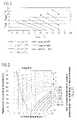
- FIG. 1shows an example for a map of a compressor with details of the surge limit, of the undisturbed operating line, and of the operating line which is shifted by temperature deviations;
- FIG. 2shows an example for a map of a gas turbine, which specifies the maximum temperature fluctuations which are allowed to occur for avoiding surging at different RPMs of the compressor;
- FIG. 3shows an example for the limitation of the operating range of the evaporative cooling according to the method under consideration
- FIG. 4shows an example for an empirically determined interrelationship between the maximal temperature drop which is achievable by the evaporative cooling, and the temperature fluctuation resulting from it;
- FIG. 5shows a second example for the limitation of the operating range of the evaporative cooling according to the method under consideration.
- FIG. 6shows an example for the procedure for monitoring of the evaporative cooling.
- FIG. 1exemplarily shows a map of a compressor of a gas turbine, in which are drawn the surge limit 1 , the undisturbed operating line 2 and also the operating line 3 which is shifted by temperature fluctuations. Furthermore, the lines of constant RPM of the compressor at different RPMs n* (as a fractional part of the rated RPM) are visible. Such a method of presentation is familiar to a person skilled in the art.
- an operating characteristicbased on an operating point 4 , is shown in the right hand section of the figure, in which the operating point by 1% contamination on the operating line 2 is shifted first to a somewhat reduced flow, and then by temperature fluctuations with a fluctuation amplitude of 20° C. is shifted onto an operating point 5 on the shifted operating line 3 . From the map, it is evident that in this operating range there is no risk of surging since there is still a sufficient distance from the surge limit 1 .
- FIG. 2shows a typical map of a compressor in which are entered the temperature fluctuations which are the maximum tolerable for avoiding surging in dependence upon different RPMs of the compressor (in a percentage of the rated speed), as can be produced by mains fluctuations.
- the maximum tolerable temperature fluctuationsin addition to the RPM, are also dependent upon the ambient temperature, i.e., the temperature without evaporative cooling.
- the temperatures at different pointsare continually monitored by the arrangement of temperature sensors in the air induction pipe, in order to detect in good time an exceeding of the maximum tolerable temperature fluctuations which are entered in such a map.
- the maximum possible temperature fluctuationswhich are achievable by the applied evaporative cooling in predetermined environmental conditions, are smaller than the maximum tolerable temperature fluctuations in these environmental conditions.
- the maximum possible temperature fluctuationcorresponds to the difference between the ambient temperature and the wet-bulb temperature with a predetermined relative air humidity.
- FIG. 3This calculable interrelationship can be gathered from FIG. 3 .
- the temperature difference between the ambient temperature and the wet-bulb temperatureis entered by the system of broken lines at varying ambient temperature and varying relative humidity.
- the continuous line in the left hand section of the figureshows the icing limit, after which a formation of ice occurs as a result of the water vapor or the water droplets, as the case may be, which are introduced into the inducted air.
- Such an operating range on the left of this icing linemust not be reached during operation of the compressor, since otherwise icing occurs.
- limit lines for different RPMs of the compressor from 95% to 100%are entered in the right hand bottom corner.
- These limit linesspecify for the compressor to which they refer the ranges within which the risk of surging occurs. In the example under consideration, this means, for example, that with a RPM of 95% of the rated RPM, ranges which lie on the right hand side of the corresponding limit line must not be allowed to be reached when the evaporative cooling is switched on. Hence, if the environmental conditions, i.e., the ambient temperature and the relative humidity, lie within this range, then no evaporative cooling is operated.
- the curvesare drawn which are produced on the assumption of a resulting temperature fluctuation which corresponds to 50%, 80%, or 100% of the amplitude of the temperature drop which is achievable by the evaporative cooling. It is evident from the figure that the curves at 80% and 50% lie closer to reality than the curve at 100%.
- an interrelationshipis fixed in which the temperature fluctuation which results from the evaporative cooling corresponds to 80% of the maximum possible temperature drop by means of the evaporative cooling.
- FIG. 5shows the same data as already described in FIG. 3 .
- the limitation of the operating range of the evaporative coolingis smaller, so that in the right hand bottom section of the figure a smaller prohibited range is produced, within which the evaporative cooling must not be operated.
- the injection system of the evaporative coolingshould be suitably designed in front of the compressor inlet.
- the individual nozzles or nozzle stagesshould be installed symmetrically inside the cross section of the air induction pipe.
- the nozzleslie closer to each other in regions of higher flow velocity of the inducted air than in regions of lower flow velocity, so that a maximum uniformity of the saturated flow in the air induction flow ensues.
- the higher flow velocities of the inducted airoccur mainly in the central region so that in this region there should be a correspondingly closer arrangement of the injection nozzles than in the other regions.
- FIG. 6finally schematically shows a further development in which the pressure in the feed line 8 of the evaporative cooling is monitored by a pressure measuring device 9 in order to shut off the feed by a control unit 10 in the event of the exceeding or falling below of a limiting value of this pressure, which preferably lies between 120*10 5 Pa (120 bar) and 180*10 5 Pa (180 bar). Furthermore, in the development which is shown, the mass flow in the feed line 8 is measured by a measuring device 11 during operation, and with a difference of more than 5% of a rated value the evaporative cooling is also shut down.
Landscapes
- Engineering & Computer Science (AREA)
- Chemical & Material Sciences (AREA)
- Combustion & Propulsion (AREA)
- Mechanical Engineering (AREA)
- General Engineering & Computer Science (AREA)
- Control Of Positive-Displacement Air Blowers (AREA)
- Control Of Turbines (AREA)
- Structures Of Non-Positive Displacement Pumps (AREA)
- Control Of Positive-Displacement Pumps (AREA)
Abstract
Description
{dot over (m)}=ρχ
is satisfied.
{dot over (m)}=ρχ
Claims (6)
Applications Claiming Priority (3)
| Application Number | Priority Date | Filing Date | Title |
|---|---|---|---|
| CH01045/04 | 2004-06-22 | ||
| CH01045/04ACH697258B1 (en) | 2004-06-22 | 2004-06-22 | A method of operating a gas turbine. |
| PCT/EP2005/052709WO2005124125A1 (en) | 2004-06-22 | 2005-06-13 | Method for operating a gas turbine compressor while cooling the compressor intake air by evaporation |
Related Parent Applications (1)
| Application Number | Title | Priority Date | Filing Date |
|---|---|---|---|
| PCT/EP2005/052709ContinuationWO2005124125A1 (en) | 2004-06-22 | 2005-06-13 | Method for operating a gas turbine compressor while cooling the compressor intake air by evaporation |
Publications (2)
| Publication Number | Publication Date |
|---|---|
| US20070084212A1 US20070084212A1 (en) | 2007-04-19 |
| US7428819B2true US7428819B2 (en) | 2008-09-30 |
Family
ID=34970040
Family Applications (1)
| Application Number | Title | Priority Date | Filing Date |
|---|---|---|---|
| US11/562,482Expired - Fee RelatedUS7428819B2 (en) | 2004-06-22 | 2006-11-22 | Method for the operation of a compressor of a gas turbine with evaporative cooling of the compressor induction air |
Country Status (8)
| Country | Link |
|---|---|
| US (1) | US7428819B2 (en) |
| EP (1) | EP1759103B1 (en) |
| AT (1) | ATE389103T1 (en) |
| AU (1) | AU2005254723B2 (en) |
| CH (1) | CH697258B1 (en) |
| DE (1) | DE502005003215D1 (en) |
| ES (1) | ES2302204T3 (en) |
| WO (1) | WO2005124125A1 (en) |
Cited By (23)
| Publication number | Priority date | Publication date | Assignee | Title |
|---|---|---|---|---|
| US9441542B2 (en) | 2011-09-20 | 2016-09-13 | General Electric Company | Ultrasonic water atomization system for gas turbine inlet cooling and wet compression |
| US9664070B1 (en) | 2016-02-12 | 2017-05-30 | United Technologies Corporation | Bowed rotor prevention system |
| US10040577B2 (en) | 2016-02-12 | 2018-08-07 | United Technologies Corporation | Modified start sequence of a gas turbine engine |
| US10125691B2 (en) | 2016-02-12 | 2018-11-13 | United Technologies Corporation | Bowed rotor start using a variable position starter valve |
| US10125636B2 (en) | 2016-02-12 | 2018-11-13 | United Technologies Corporation | Bowed rotor prevention system using waste heat |
| US10174678B2 (en) | 2016-02-12 | 2019-01-08 | United Technologies Corporation | Bowed rotor start using direct temperature measurement |
| US10221774B2 (en) | 2016-07-21 | 2019-03-05 | United Technologies Corporation | Speed control during motoring of a gas turbine engine |
| US10358936B2 (en) | 2016-07-05 | 2019-07-23 | United Technologies Corporation | Bowed rotor sensor system |
| US10384791B2 (en) | 2016-07-21 | 2019-08-20 | United Technologies Corporation | Cross engine coordination during gas turbine engine motoring |
| US10436064B2 (en) | 2016-02-12 | 2019-10-08 | United Technologies Corporation | Bowed rotor start response damping system |
| US10443543B2 (en) | 2016-11-04 | 2019-10-15 | United Technologies Corporation | High compressor build clearance reduction |
| US10443505B2 (en) | 2016-02-12 | 2019-10-15 | United Technologies Corporation | Bowed rotor start mitigation in a gas turbine engine |
| US10443507B2 (en) | 2016-02-12 | 2019-10-15 | United Technologies Corporation | Gas turbine engine bowed rotor avoidance system |
| US10508601B2 (en) | 2016-02-12 | 2019-12-17 | United Technologies Corporation | Auxiliary drive bowed rotor prevention system for a gas turbine engine |
| US10508567B2 (en) | 2016-02-12 | 2019-12-17 | United Technologies Corporation | Auxiliary drive bowed rotor prevention system for a gas turbine engine through an engine accessory |
| US10539079B2 (en) | 2016-02-12 | 2020-01-21 | United Technologies Corporation | Bowed rotor start mitigation in a gas turbine engine using aircraft-derived parameters |
| US10598047B2 (en) | 2016-02-29 | 2020-03-24 | United Technologies Corporation | Low-power bowed rotor prevention system |
| US10618666B2 (en) | 2016-07-21 | 2020-04-14 | United Technologies Corporation | Pre-start motoring synchronization for multiple engines |
| US10633106B2 (en) | 2016-07-21 | 2020-04-28 | United Technologies Corporation | Alternating starter use during multi-engine motoring |
| US10787933B2 (en) | 2016-06-20 | 2020-09-29 | Raytheon Technologies Corporation | Low-power bowed rotor prevention and monitoring system |
| US10787968B2 (en) | 2016-09-30 | 2020-09-29 | Raytheon Technologies Corporation | Gas turbine engine motoring with starter air valve manual override |
| US10823079B2 (en) | 2016-11-29 | 2020-11-03 | Raytheon Technologies Corporation | Metered orifice for motoring of a gas turbine engine |
| US11047257B2 (en) | 2016-07-21 | 2021-06-29 | Raytheon Technologies Corporation | Multi-engine coordination during gas turbine engine motoring |
Families Citing this family (2)
| Publication number | Priority date | Publication date | Assignee | Title |
|---|---|---|---|---|
| CH697258B1 (en) | 2004-06-22 | 2008-07-31 | Alstom Technology Ltd | A method of operating a gas turbine. |
| IL199803A (en) | 2009-07-12 | 2012-07-31 | Lv Technologies Ltd | Method and system for enhancing engine performance |
Citations (7)
| Publication number | Priority date | Publication date | Assignee | Title |
|---|---|---|---|---|
| US5463873A (en) | 1993-12-06 | 1995-11-07 | Cool Fog Systems, Inc. | Method and apparatus for evaporative cooling of air leading to a gas turbine engine |
| EP0889212A2 (en) | 1997-06-30 | 1999-01-07 | Hitachi, Ltd. | Gas turbine |
| DE19913681A1 (en) | 1999-03-25 | 2000-10-05 | Saar En Gmbh | Method for generating electrical energy in a gas turbine process |
| EP1203866A2 (en) | 2000-11-06 | 2002-05-08 | General Electric Company | Apparatus and methods for controlling the supply of water mist to a gas-turbine compressor |
| EP1231369A2 (en) | 2001-02-07 | 2002-08-14 | General Electric Company | Gas turbine control system compensating water content in combustion air |
| WO2003058047A1 (en) | 2002-01-07 | 2003-07-17 | Alstom Technology Ltd | Method for operating a gas turbine group |
| WO2005124125A1 (en) | 2004-06-22 | 2005-12-29 | Alstom Technology Ltd | Method for operating a gas turbine compressor while cooling the compressor intake air by evaporation |
- 2004
- 2004-06-22CHCH01045/04Apatent/CH697258B1/ennot_activeIP Right Cessation
- 2005
- 2005-06-13ATAT05752828Tpatent/ATE389103T1/ennot_activeIP Right Cessation
- 2005-06-13ESES05752828Tpatent/ES2302204T3/ennot_activeExpired - Lifetime
- 2005-06-13AUAU2005254723Apatent/AU2005254723B2/ennot_activeCeased
- 2005-06-13EPEP05752828Apatent/EP1759103B1/ennot_activeExpired - Lifetime
- 2005-06-13DEDE502005003215Tpatent/DE502005003215D1/ennot_activeExpired - Lifetime
- 2005-06-13WOPCT/EP2005/052709patent/WO2005124125A1/enactiveIP Right Grant
- 2006
- 2006-11-22USUS11/562,482patent/US7428819B2/ennot_activeExpired - Fee Related
Patent Citations (8)
| Publication number | Priority date | Publication date | Assignee | Title |
|---|---|---|---|---|
| US5463873A (en) | 1993-12-06 | 1995-11-07 | Cool Fog Systems, Inc. | Method and apparatus for evaporative cooling of air leading to a gas turbine engine |
| EP0889212A2 (en) | 1997-06-30 | 1999-01-07 | Hitachi, Ltd. | Gas turbine |
| US6260350B1 (en)* | 1997-06-30 | 2001-07-17 | Hitachi, Ltd. | Gas turbine |
| DE19913681A1 (en) | 1999-03-25 | 2000-10-05 | Saar En Gmbh | Method for generating electrical energy in a gas turbine process |
| EP1203866A2 (en) | 2000-11-06 | 2002-05-08 | General Electric Company | Apparatus and methods for controlling the supply of water mist to a gas-turbine compressor |
| EP1231369A2 (en) | 2001-02-07 | 2002-08-14 | General Electric Company | Gas turbine control system compensating water content in combustion air |
| WO2003058047A1 (en) | 2002-01-07 | 2003-07-17 | Alstom Technology Ltd | Method for operating a gas turbine group |
| WO2005124125A1 (en) | 2004-06-22 | 2005-12-29 | Alstom Technology Ltd | Method for operating a gas turbine compressor while cooling the compressor intake air by evaporation |
Non-Patent Citations (4)
| Title |
|---|
| International Preliminary Report on Patentability for PCT Patent App. No. PCT/EP2005/052709 (Sep. 13, 2006). |
| International Search Report for PCT Patent App. No. PCT/EP2005/052709 (Sep. 13, 2005). |
| PCT/EP2005/052709 IPER, English translation.* |
| Search Report for Swiss Patent App. No. 1045/2004 (Sep. 1, 2004). |
Cited By (31)
| Publication number | Priority date | Publication date | Assignee | Title |
|---|---|---|---|---|
| US9441542B2 (en) | 2011-09-20 | 2016-09-13 | General Electric Company | Ultrasonic water atomization system for gas turbine inlet cooling and wet compression |
| US10801371B2 (en) | 2016-02-12 | 2020-10-13 | Raytheon Technologies Coproration | Bowed rotor prevention system |
| US10787277B2 (en) | 2016-02-12 | 2020-09-29 | Raytheon Technologies Corporation | Modified start sequence of a gas turbine engine |
| US10125691B2 (en) | 2016-02-12 | 2018-11-13 | United Technologies Corporation | Bowed rotor start using a variable position starter valve |
| US10125636B2 (en) | 2016-02-12 | 2018-11-13 | United Technologies Corporation | Bowed rotor prevention system using waste heat |
| US10174678B2 (en) | 2016-02-12 | 2019-01-08 | United Technologies Corporation | Bowed rotor start using direct temperature measurement |
| US11274604B2 (en) | 2016-02-12 | 2022-03-15 | Raytheon Technologies Corporation | Bowed rotor start mitigation in a gas turbine engine using aircraft-derived parameters |
| US9664070B1 (en) | 2016-02-12 | 2017-05-30 | United Technologies Corporation | Bowed rotor prevention system |
| US10625881B2 (en) | 2016-02-12 | 2020-04-21 | United Technologies Corporation | Modified start sequence of a gas turbine engine |
| US10040577B2 (en) | 2016-02-12 | 2018-08-07 | United Technologies Corporation | Modified start sequence of a gas turbine engine |
| US10443505B2 (en) | 2016-02-12 | 2019-10-15 | United Technologies Corporation | Bowed rotor start mitigation in a gas turbine engine |
| US10436064B2 (en) | 2016-02-12 | 2019-10-08 | United Technologies Corporation | Bowed rotor start response damping system |
| US10443507B2 (en) | 2016-02-12 | 2019-10-15 | United Technologies Corporation | Gas turbine engine bowed rotor avoidance system |
| US10508601B2 (en) | 2016-02-12 | 2019-12-17 | United Technologies Corporation | Auxiliary drive bowed rotor prevention system for a gas turbine engine |
| US10508567B2 (en) | 2016-02-12 | 2019-12-17 | United Technologies Corporation | Auxiliary drive bowed rotor prevention system for a gas turbine engine through an engine accessory |
| US10539079B2 (en) | 2016-02-12 | 2020-01-21 | United Technologies Corporation | Bowed rotor start mitigation in a gas turbine engine using aircraft-derived parameters |
| US10598047B2 (en) | 2016-02-29 | 2020-03-24 | United Technologies Corporation | Low-power bowed rotor prevention system |
| US10787933B2 (en) | 2016-06-20 | 2020-09-29 | Raytheon Technologies Corporation | Low-power bowed rotor prevention and monitoring system |
| US10358936B2 (en) | 2016-07-05 | 2019-07-23 | United Technologies Corporation | Bowed rotor sensor system |
| US10633106B2 (en) | 2016-07-21 | 2020-04-28 | United Technologies Corporation | Alternating starter use during multi-engine motoring |
| US10618666B2 (en) | 2016-07-21 | 2020-04-14 | United Technologies Corporation | Pre-start motoring synchronization for multiple engines |
| US10384791B2 (en) | 2016-07-21 | 2019-08-20 | United Technologies Corporation | Cross engine coordination during gas turbine engine motoring |
| US11047257B2 (en) | 2016-07-21 | 2021-06-29 | Raytheon Technologies Corporation | Multi-engine coordination during gas turbine engine motoring |
| US11142329B2 (en) | 2016-07-21 | 2021-10-12 | Raytheon Technologies Corporation | Pre-start motoring synchronization for multiple engines |
| US10221774B2 (en) | 2016-07-21 | 2019-03-05 | United Technologies Corporation | Speed control during motoring of a gas turbine engine |
| US11674411B2 (en) | 2016-07-21 | 2023-06-13 | Raytheon Technologies Corporation | Multi-engine coordination during gas turbine engine motoring |
| US11807378B2 (en) | 2016-07-21 | 2023-11-07 | Rtx Corporation | Alternating starter use during multi-engine motoring |
| US11840968B2 (en) | 2016-07-21 | 2023-12-12 | Rtx Corporation | Motoring synchronization for multiple engines |
| US10787968B2 (en) | 2016-09-30 | 2020-09-29 | Raytheon Technologies Corporation | Gas turbine engine motoring with starter air valve manual override |
| US10443543B2 (en) | 2016-11-04 | 2019-10-15 | United Technologies Corporation | High compressor build clearance reduction |
| US10823079B2 (en) | 2016-11-29 | 2020-11-03 | Raytheon Technologies Corporation | Metered orifice for motoring of a gas turbine engine |
Also Published As
| Publication number | Publication date |
|---|---|
| CH697258B1 (en) | 2008-07-31 |
| AU2005254723A1 (en) | 2005-12-29 |
| ES2302204T3 (en) | 2008-07-01 |
| WO2005124125A1 (en) | 2005-12-29 |
| AU2005254723B2 (en) | 2008-12-18 |
| DE502005003215D1 (en) | 2008-04-24 |
| EP1759103A1 (en) | 2007-03-07 |
| EP1759103B1 (en) | 2008-03-12 |
| US20070084212A1 (en) | 2007-04-19 |
| ATE389103T1 (en) | 2008-03-15 |
Similar Documents
| Publication | Publication Date | Title |
|---|---|---|
| US7428819B2 (en) | Method for the operation of a compressor of a gas turbine with evaporative cooling of the compressor induction air | |
| US6231306B1 (en) | Control system for preventing compressor stall | |
| US7650777B1 (en) | Stall and surge detection system and method | |
| US6438484B1 (en) | Method and apparatus for detecting and compensating for compressor surge in a gas turbine using remote monitoring and diagnostics | |
| EP0654163B1 (en) | Process and device for monitoring vibrational excitation of an axial compressor | |
| US8827630B2 (en) | Method and system for determining gas turbine tip clearance | |
| TWI386557B (en) | Method for detecting rotating stall in a compressor | |
| US9862495B2 (en) | Aircraft air-conditioning heat exchanger contamination detection | |
| EP1231369A2 (en) | Gas turbine control system compensating water content in combustion air | |
| US20210131441A1 (en) | Apparatus and Method for Diagnosing and Controlling Aerodynamic Stability of Compressor | |
| JPH08503757A (en) | Method and apparatus for monitoring and controlling a compressor | |
| US20060283190A1 (en) | Engine status detection with external microphone | |
| CN104114874B (en) | Method for avoiding pump surge in a compressor | |
| JP5977503B2 (en) | Surge precursor protection system and method | |
| CN110382878A (en) | Determine the method and apparatus and application thereof for predicting instable index in compressor | |
| JP4565282B2 (en) | Surge detection method for centrifugal compressor | |
| Peters et al. | Effects of rotating inlet distortion on a 5-stage HP-compressor | |
| US7269954B2 (en) | Method for operating a gas turbine installation, and gas turbine installation | |
| CN1329726C (en) | Method for testing the cleanliness of the filter screen | |
| JPH01394A (en) | Compressor surging prevention device | |
| JP7390122B2 (en) | Air conditioning system and abnormality detection system | |
| JP2006105053A (en) | Gas turbine monitoring device and gas turbine monitoring system | |
| KR100543671B1 (en) | Compressor swing stall warning device and method using space Fourier coefficient | |
| HK1092864B (en) | A method and apparatus for detecting surge in a refrigeration system and a centrifugal compressor | |
| JP2003161158A (en) | Overrun detecting method for variable vane turbo system |
Legal Events
| Date | Code | Title | Description |
|---|---|---|---|
| AS | Assignment | Owner name:ALSTOM TECHNOLOGY LTD, SWITZERLAND Free format text:ASSIGNMENT OF ASSIGNORS INTEREST;ASSIGNORS:CATALDI, GIOVANNI;FAEHNDRICH, CHRISTIAN;MATZ, CHARLES;REEL/FRAME:018702/0056;SIGNING DATES FROM 20061204 TO 20061207 | |
| STCF | Information on status: patent grant | Free format text:PATENTED CASE | |
| FPAY | Fee payment | Year of fee payment:4 | |
| FEPP | Fee payment procedure | Free format text:PAYOR NUMBER ASSIGNED (ORIGINAL EVENT CODE: ASPN); ENTITY STATUS OF PATENT OWNER: LARGE ENTITY | |
| AS | Assignment | Owner name:GENERAL ELECTRIC TECHNOLOGY GMBH, SWITZERLAND Free format text:CHANGE OF NAME;ASSIGNOR:ALSTOM TECHNOLOGY LTD;REEL/FRAME:038216/0193 Effective date:20151102 | |
| FPAY | Fee payment | Year of fee payment:8 | |
| AS | Assignment | Owner name:ANSALDO ENERGIA IP UK LIMITED, GREAT BRITAIN Free format text:ASSIGNMENT OF ASSIGNORS INTEREST;ASSIGNOR:GENERAL ELECTRIC TECHNOLOGY GMBH;REEL/FRAME:041731/0626 Effective date:20170109 | |
| FEPP | Fee payment procedure | Free format text:MAINTENANCE FEE REMINDER MAILED (ORIGINAL EVENT CODE: REM.); ENTITY STATUS OF PATENT OWNER: LARGE ENTITY | |
| LAPS | Lapse for failure to pay maintenance fees | Free format text:PATENT EXPIRED FOR FAILURE TO PAY MAINTENANCE FEES (ORIGINAL EVENT CODE: EXP.); ENTITY STATUS OF PATENT OWNER: LARGE ENTITY | |
| STCH | Information on status: patent discontinuation | Free format text:PATENT EXPIRED DUE TO NONPAYMENT OF MAINTENANCE FEES UNDER 37 CFR 1.362 | |
| FP | Lapsed due to failure to pay maintenance fee | Effective date:20200930 |