US7428147B2 - Mounting apparatus for storage device - Google Patents
Mounting apparatus for storage deviceDownload PDFInfo
- Publication number
- US7428147B2 US7428147B2US11/321,587US32158705AUS7428147B2US 7428147 B2US7428147 B2US 7428147B2US 32158705 AUS32158705 AUS 32158705AUS 7428147 B2US7428147 B2US 7428147B2
- Authority
- US
- United States
- Prior art keywords
- bracket
- sidewall
- slider
- mounting apparatus
- retainer
- Prior art date
- Legal status (The legal status is an assumption and is not a legal conclusion. Google has not performed a legal analysis and makes no representation as to the accuracy of the status listed.)
- Expired - Fee Related, expires
Links
- 230000007246mechanismEffects0.000claimsdescription7
- 230000002860competitive effectEffects0.000description2
- 238000009434installationMethods0.000description2
- 101150095407Bfar geneProteins0.000description1
- 230000000994depressogenic effectEffects0.000description1
- 210000005224forefingerAnatomy0.000description1
- 238000004519manufacturing processMethods0.000description1
- 210000003813thumbAnatomy0.000description1
Images


Classifications
- G—PHYSICS
- G11—INFORMATION STORAGE
- G11B—INFORMATION STORAGE BASED ON RELATIVE MOVEMENT BETWEEN RECORD CARRIER AND TRANSDUCER
- G11B33/00—Constructional parts, details or accessories not provided for in the other groups of this subclass
- G11B33/12—Disposition of constructional parts in the apparatus, e.g. of power supply, of modules
- G11B33/125—Disposition of constructional parts in the apparatus, e.g. of power supply, of modules the apparatus comprising a plurality of recording/reproducing devices, e.g. modular arrangements, arrays of disc drives
- G11B33/127—Mounting arrangements of constructional parts onto a chassis
- G11B33/128—Mounting arrangements of constructional parts onto a chassis of the plurality of recording/reproducing devices, e.g. disk drives, onto a chassis
- G—PHYSICS
- G11—INFORMATION STORAGE
- G11B—INFORMATION STORAGE BASED ON RELATIVE MOVEMENT BETWEEN RECORD CARRIER AND TRANSDUCER
- G11B33/00—Constructional parts, details or accessories not provided for in the other groups of this subclass
- G11B33/12—Disposition of constructional parts in the apparatus, e.g. of power supply, of modules
- G11B33/121—Disposition of constructional parts in the apparatus, e.g. of power supply, of modules the apparatus comprising a single recording/reproducing device
- G11B33/123—Mounting arrangements of constructional parts onto a chassis
- G11B33/124—Mounting arrangements of constructional parts onto a chassis of the single recording/reproducing device, e.g. disk drive, onto a chassis
Definitions
- the present inventionrelates to a mounting apparatus, and more particularly to a mounting apparatus for a storage device.
- An electronic apparatussuch as a typical desktop computer, a tower computer, a server, and the like, usually includes storage devices, such as hard disk drives, compact disk read-only memory (CD-ROM) drives, digital video disc (DVD) drives, floppy disk drives, and the like. These devices are typically added to increase the functionality of the electronic apparatus as desired by a user. However, the installation of such devices in the electronic apparatus is always labor-intensive.
- CD-ROMcompact disk read-only memory
- DVDdigital video disc
- a plurality of mounting apparatusesis invented to reduce the number of needed screws.
- a pair of detachable railsis attached to opposite sides of a storage device with screws.
- the storage deviceslides into and is secured to a drive bracket.
- the screwshave to be removed to detach the rails from the storage device before replacing the storage device.
- a mounting apparatusin one preferred embodiment, includes a bracket, a retainer, and a slider.
- the bracketis for receiving a storage device therein and includes a first sidewall defining two pairs of apertures therein.
- the slideris slidably attached to the first sidewall and includes two pairs of slideways, and a pair of resilient arms.
- the retaineris sandwiched between the first sidewall of the bracket and the slider and abutted against by the resilient arms.
- the retainerincludes two pairs of posts sliding along the slideways, and two pairs of pins extending through the apertures to engage the storage device.
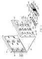
- FIG. 1is an exploded, isometric view of a mounting apparatus in accordance with a preferred embodiment of the present invention
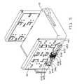
- FIG. 2is similar to FIG. 1 , but viewed from another aspect
- FIG. 3is an assembled view of the mounting apparatus of FIG. 2 , together with a storage device;
- FIG. 4is an assembled view of the mounting apparatus of FIG. 1 , with the storage device installed therein;
- FIG. 5is similar to FIG. 4 , but viewed from another aspect.
- a mounting apparatus of an electronic device like a computerfor holding a functional device like a storage device 10 of the computer in place.
- the mounting apparatusincludes a bracket 30 , a retainer 50 , and a slider 60 .
- the storage device 10includes a top wall 11 , and a pair of sidewalls 12 perpendicular to the top wall 11 . Two pairs of spaced fixing holes 14 are defined in each of the sidewalls 12 .
- the bracket 30includes a bottom wall 32 , a first sidewall 34 , and a second sidewall 36 .
- a pair of guiding pieces 362is punched inwardly and separately from the first and second sidewalls 34 , 36 , opposite to each other.
- Two lines of spaced bridges 345 each with a guiding protrusion 346are punched outwardly from the first sidewall 34 so as to be used as a guide mechanism of the bracket 30 .
- Two lines of spaced guiding tabs 348are punched outwardly from the first sidewall 34 , between the lines of the bridges 345 .
- a locating tab 349is punched outwardly from the first sidewall 34 , between the lines of the guiding tabs 348 so as to be used as another guide mechanism of the bracket 30 .
- a many pairs of apertures 344 in arrayare defined in the first sidewall 34 besides two ends of the guiding tabs 348 , corresponding to the fixing holes 14 of the storage device 10 .
- Many slots 347 in arrayare defined in a rear portion of the first sidewall 34 beside the apertures.
- Many pairs of resilient tabs 364 in arrayextend inwardly from the second sidewall 36 along the horizontal direction.
- a protrusion 366extrudes from each of the resilient tabs 364 in alignment with the corresponding aperture 344 of the first sidewall 34 .
- the retainer 50includes a rectangle plate 51 , and a pair of flanges 55 extended perpendicularly and outwardly from upper and lower edges of the rectangle plate 51 respectively. Many slits 52 in array are defined in the rectangle plate 51 , corresponding to the locating tab 349 of the bracket 30 . A tip 54 extends perpendicularly at each comer of the rectangle plate 51 , corresponding to the apertures 344 of the bracket 30 . A pair of posts 56 extends outwardly from end portions of each flange 55 . The post 56 can be replaced by another sliding member, such as a block or a protrusion.
- the slider 60is generally box-shaped.
- the slider 60includes a vertical wall 62 , and a pair of horizontal walls 64 extending inwardly from upper and lower edges of the vertical wall 62 respectively.
- a pair of resilient arms 623extends inwardly from two opposite end portions of the vertical wall 62 and the resilient arms 623 symmetrically extend toward each other. Each of the resilient arms has a curved distal end.
- a handgrip portion 624is defined in a middle portion of the vertical wall 62 and extends to the horizontal walls 64 .
- a pair of sliding blocks 642extends from an edge of each of the horizontal walls 64 , corresponding to guiding protrusions 346 of the bridges 345 of the bracket 30 .
- a resilient hook 648extends outwardly from the edge portion of each of the horizontal walls 64 between corresponding guiding blocks 642 , engaging with corresponding guiding tabs 348 of the bracket 30 .
- a pair of slideways 644is formed in each of the horizontal walls 64 besides the handgrip portion 624 .
- a recess 647is defined in each of the horizontal walls 64 connecting with the corresponding slideway 644 .
- Each of the slideways 644includes a sloped wall 645 .
- Each of the slopped walls 645includes a first end 645 a near the vertical wall 62 , and a second end 645 b far away the vertical wall 62 .
- a locator 66is resiliently formed in a rear portion of the vertical wall 62 .
- the locator 66includes a plug 661 extruding inwardly therefrom, and a handle 663 extending outwardly therefrom.
- the retainer 50in assembly of the mounting apparatus, is engaged to the first sidewall 34 of the bracket 30 , with the locating tab 349 engaged in one of the slots 52 and the tips 54 in alignment with corresponding apertures 344 .
- the slider 60is placed on the first sidewall 34 , with the hooks 648 sliding between corresponding guiding tabs 348 .
- the guiding blocks 642 of the slider 60slide along the guiding protrusions 346 of the bridges 345 .
- the sliding posts 56 of the retainer 50are received in the corresponding slidaways 644 via the corresponding recesses 647 .
- the plug 661 of the slider 60engages in corresponding slit 347 of the bracket 30 .
- the curved distal ends of the resilient arms 623slidably contact and abut against the retainer 50 .
- the resilient arms 623therefore urge the rectangle plate 51 toward the first sidewall 34 of the bracket 30 , with the tips 54 extending through corresponding aperture 344 of the bracket 30 .
- FIGS. 4 and 5show the storage device 10 fixed in the bracket 30 .
- the handle 663is drawn outwardly to release the plug 661 from the slot 347 of the bracket 30 by a forefinger of an operator.
- the handgrip portion 624is engaged by a thumb of the operator to push the slider 60 rearward, with the guiding blocks 642 moving along corresponding guiding protrusions 346 of the bridges 345 correspondingly.
- the sliding posts 56 of the retainer 50slide along corresponding sloped wall 645 from the second end 645 b to the first end 645 a .
- the resilient arms 623are restored to move the retainer 50 away from the first sidewall 34 of the bracket 30 .
- the tips 54 of the retainer 50disengage from corresponding apertures 344 of the first sidewall 34 of the bracket 30 . Then the storage device 10 is moved into the bracket 30 , with the guiding pieces 362 engaging on the top wall 11 of the storage device 10 and the resilient tabs 364 abutting the sidewalls 12 of the storage device 10 . When a rear pair of fixing holes 14 of the storage device 10 approximately reaches one front pair of the apertures 344 of the bracket 30 , the slider 60 is pushed frontward. The sliding posts 56 of the retainer 50 slide along corresponding sloped wall 645 from the first end 645 a to the second end 645 b . The resilient arms 623 are depressed to urge the retainer 50 toward the first sidewall 34 .
- the tips 54 of the retainer 50are extended through the apertures 344 to abut the sidewall 12 of the storage device 10 .
- the tips 54are extended into the fixing holes 14 .
- the protrusions 366 of the second sidewall 36 of the bracketengage in the fixing holes 14 of an opposite sidewall of the storage devices 10 .
- the plug 661 of the slider 60engages in the corresponding slot 347 of the bracket 30 .
- the storage device 10is fixed in the bracket 30 .
- the storage device 10is selectively located in different positions in the bracket 30 , so that the bracket 30 is able to receive the storage device 10 in a plurality of selective places therein, with the tips 54 of the retainer 50 engaging in different pairs of the apertures 344 of the bracket 30 , the locating tab 349 of the bracket 30 engaging in different slits 52 of the retainer 50 , the plug 661 of the slider 60 engaging in different slots 347 of the bracket 30 , and the fixing holes 14 of the storage device 10 engaging with different protrusions 366 of the bracket 30 .
- the retainer 50therefore can be attached to the slider 60 in a selective place corresponding to a selected place of the storage device 10 in the bracket and is movable in a direction perpendicular to the bracket.
- the handle 663 of the slider 60is drawn outwardly to separate the plug 661 from the slot 347 .
- the slider 60is moved rearward, the sliding posts 56 of the retainer 50 slide along the corresponding sloped walls 645 from the second end 645 b to the first end 645 a .
- the resilient arms 623are restored to move the retainer 50 away from the first sidewall 34 of the bracket 30 .
- the tips 54withdraw from the fixing holes 14 of the storage device 10 .
- the storage device 10is easily detached from the bracket 30 .
Landscapes
- Casings For Electric Apparatus (AREA)
Abstract
Description
Claims (20)
Applications Claiming Priority (2)
| Application Number | Priority Date | Filing Date | Title |
|---|---|---|---|
| CN200520054534.9 | 2005-01-29 | ||
| CNU2005200545349UCN2785022Y (en) | 2005-01-29 | 2005-01-29 | Data storage device fixing equipment |
Publications (2)
| Publication Number | Publication Date |
|---|---|
| US20060231686A1 US20060231686A1 (en) | 2006-10-19 |
| US7428147B2true US7428147B2 (en) | 2008-09-23 |
Family
ID=36771989
Family Applications (1)
| Application Number | Title | Priority Date | Filing Date |
|---|---|---|---|
| US11/321,587Expired - Fee RelatedUS7428147B2 (en) | 2005-01-29 | 2005-12-29 | Mounting apparatus for storage device |
Country Status (2)
| Country | Link |
|---|---|
| US (1) | US7428147B2 (en) |
| CN (1) | CN2785022Y (en) |
Cited By (9)
| Publication number | Priority date | Publication date | Assignee | Title |
|---|---|---|---|---|
| US20090310294A1 (en)* | 2008-06-13 | 2009-12-17 | Chia-Pin Hsieh | Screw-less fastening device |
| US20100149747A1 (en)* | 2008-12-12 | 2010-06-17 | Hong Fu Jin Precision Industry (Shenzhen) Co., Ltd | Retaining apparatus for locking disk drive |
| US20100172085A1 (en)* | 2009-01-06 | 2010-07-08 | Shu-Nan Lee | Fastening device for computer read/write or storage device |
| US20100288898A1 (en)* | 2009-05-12 | 2010-11-18 | Hon Fu Jin Precision Industry (Shenzhen) Co., Ltd. | Mounting apparatus for data storage device |
| US20110049319A1 (en)* | 2009-08-28 | 2011-03-03 | Hong Fu Jin Precision Industry (Shenzhen) Co. Ltd. | Mounting apparatus for data storage device |
| US20110255243A1 (en)* | 2010-04-14 | 2011-10-20 | Jo-Chiao Wang | Fixing mechanism for fixing a portable device and related computer system |
| US20120169198A1 (en)* | 2010-12-31 | 2012-07-05 | Lite-On Technology Corporation | Assembly unit and casing having the same |
| US20130039014A1 (en)* | 2011-08-10 | 2013-02-14 | Hon Hai Precision Industry Co., Ltd. | Mounting apparatus for data storage device |
| US20240334638A1 (en)* | 2023-03-28 | 2024-10-03 | Fulian Precision Electronics (Tianjin) Co., Ltd. | Functional module securing device and data processing equipment |
Families Citing this family (9)
| Publication number | Priority date | Publication date | Assignee | Title |
|---|---|---|---|---|
| CN2673041Y (en)* | 2003-11-29 | 2005-01-19 | 鸿富锦精密工业(深圳)有限公司 | Data accessor fixer |
| CN2689656Y (en)* | 2004-03-06 | 2005-03-30 | 鸿富锦精密工业(深圳)有限公司 | Fixer of data memory |
| CN2862258Y (en)* | 2005-11-15 | 2007-01-24 | 鸿富锦精密工业(深圳)有限公司 | data storage fixture |
| CN101179915B (en)* | 2006-11-09 | 2011-09-07 | 泰商泰达电子公司 | Detachable electronic device for matching embedded type orbit and holding structure thereof |
| TWI349843B (en)* | 2008-05-30 | 2011-10-01 | Asustek Comp Inc | Fixing component and case having the fixing component |
| CN102445969A (en)* | 2010-10-14 | 2012-05-09 | 鸿富锦精密工业(深圳)有限公司 | Data storage fixing device |
| DE102011008028B4 (en)* | 2011-01-05 | 2012-09-27 | Fujitsu Technology Solutions Intellectual Property Gmbh | Spring assembly for a molded from a sheet metal housing part, computer case and manufacturing process |
| CN103687406A (en)* | 2012-08-31 | 2014-03-26 | 鸿富锦精密工业(深圳)有限公司 | electronic device |
| JP7252752B2 (en) | 2018-12-20 | 2023-04-05 | 大和化成工業株式会社 | Bracket for electronic control parts |
Citations (9)
| Publication number | Priority date | Publication date | Assignee | Title |
|---|---|---|---|---|
| US5262923A (en) | 1991-06-21 | 1993-11-16 | Tandon Corporation | Railing with grounding tabs for grounding and mounting computer components in a computer |
| US5599080A (en) | 1996-02-08 | 1997-02-04 | Ho; Hsin C. | Sliding case mounting device |
| US5683159A (en) | 1997-01-03 | 1997-11-04 | Johnson; Greg P. | Hardware mounting rail |
| US5734557A (en) | 1996-09-13 | 1998-03-31 | Deli U.S.A., L.P. | Mounting assembly for electronic equipment |
| US6385036B1 (en) | 1999-09-10 | 2002-05-07 | Robert C. Chien | Screwless computer case assembly |
| US6464085B1 (en)* | 2001-11-20 | 2002-10-15 | Enlight Corporation | CD-ROM rack |
| US6771496B1 (en)* | 2003-05-27 | 2004-08-03 | Cotytech Industrial Inc. | Computer module anchoring structure without using screws |
| US6853549B2 (en)* | 2003-03-14 | 2005-02-08 | Hon Hai Precision Ind. Co., Ltd | Mounting apparatus for data storage devices |
| US20050078445A1 (en)* | 2003-10-09 | 2005-04-14 | Hsuan-Tsung Chen | Mounting apparatus for storage device |
- 2005
- 2005-01-29CNCNU2005200545349Upatent/CN2785022Y/ennot_activeExpired - Fee Related
- 2005-12-29USUS11/321,587patent/US7428147B2/ennot_activeExpired - Fee Related
Patent Citations (9)
| Publication number | Priority date | Publication date | Assignee | Title |
|---|---|---|---|---|
| US5262923A (en) | 1991-06-21 | 1993-11-16 | Tandon Corporation | Railing with grounding tabs for grounding and mounting computer components in a computer |
| US5599080A (en) | 1996-02-08 | 1997-02-04 | Ho; Hsin C. | Sliding case mounting device |
| US5734557A (en) | 1996-09-13 | 1998-03-31 | Deli U.S.A., L.P. | Mounting assembly for electronic equipment |
| US5683159A (en) | 1997-01-03 | 1997-11-04 | Johnson; Greg P. | Hardware mounting rail |
| US6385036B1 (en) | 1999-09-10 | 2002-05-07 | Robert C. Chien | Screwless computer case assembly |
| US6464085B1 (en)* | 2001-11-20 | 2002-10-15 | Enlight Corporation | CD-ROM rack |
| US6853549B2 (en)* | 2003-03-14 | 2005-02-08 | Hon Hai Precision Ind. Co., Ltd | Mounting apparatus for data storage devices |
| US6771496B1 (en)* | 2003-05-27 | 2004-08-03 | Cotytech Industrial Inc. | Computer module anchoring structure without using screws |
| US20050078445A1 (en)* | 2003-10-09 | 2005-04-14 | Hsuan-Tsung Chen | Mounting apparatus for storage device |
Cited By (18)
| Publication number | Priority date | Publication date | Assignee | Title |
|---|---|---|---|---|
| US7830654B2 (en)* | 2008-06-13 | 2010-11-09 | Silitek Electronic (Guangzhou) Co., Ltd. | Screw-less fastening device |
| US20090310294A1 (en)* | 2008-06-13 | 2009-12-17 | Chia-Pin Hsieh | Screw-less fastening device |
| US8072745B2 (en)* | 2008-12-12 | 2011-12-06 | Hong Fu Jin Precision Industry (Shenzhen) Co., Ltd. | Retaining apparatus for locking disk drive |
| US20100149747A1 (en)* | 2008-12-12 | 2010-06-17 | Hong Fu Jin Precision Industry (Shenzhen) Co., Ltd | Retaining apparatus for locking disk drive |
| US20100172085A1 (en)* | 2009-01-06 | 2010-07-08 | Shu-Nan Lee | Fastening device for computer read/write or storage device |
| US7796380B2 (en)* | 2009-01-06 | 2010-09-14 | Shu-Nan Lee | Fastening device for computer read/write or storage device |
| US20100288898A1 (en)* | 2009-05-12 | 2010-11-18 | Hon Fu Jin Precision Industry (Shenzhen) Co., Ltd. | Mounting apparatus for data storage device |
| US8289691B2 (en)* | 2009-05-12 | 2012-10-16 | Hong Fu Jin Precision Industry (Shenzhen) Co., Ltd. | Mounting apparatus for data storage device |
| US20110049319A1 (en)* | 2009-08-28 | 2011-03-03 | Hong Fu Jin Precision Industry (Shenzhen) Co. Ltd. | Mounting apparatus for data storage device |
| US8369077B2 (en)* | 2009-08-28 | 2013-02-05 | Hong Fu Jin Precision Industry (Shenzhen) Co., Ltd. | Mounting apparatus for data storage device |
| US8437127B2 (en)* | 2010-04-14 | 2013-05-07 | Aopen Inc. | Fixing mechanism for fixing a portable device and related computer system |
| US20110255243A1 (en)* | 2010-04-14 | 2011-10-20 | Jo-Chiao Wang | Fixing mechanism for fixing a portable device and related computer system |
| US20120169198A1 (en)* | 2010-12-31 | 2012-07-05 | Lite-On Technology Corporation | Assembly unit and casing having the same |
| US8690267B2 (en)* | 2010-12-31 | 2014-04-08 | Lite-On Electronics (Guangzhou) Limited | Assembly unit and casing having the same |
| US20130039014A1 (en)* | 2011-08-10 | 2013-02-14 | Hon Hai Precision Industry Co., Ltd. | Mounting apparatus for data storage device |
| US8830671B2 (en)* | 2011-08-10 | 2014-09-09 | Hong Fu Jin Precision Industry (Wuhan) Co., Ltd. | Mounting apparatus for data storage device |
| US20240334638A1 (en)* | 2023-03-28 | 2024-10-03 | Fulian Precision Electronics (Tianjin) Co., Ltd. | Functional module securing device and data processing equipment |
| US12426195B2 (en)* | 2023-03-28 | 2025-09-23 | Fulian Precision Electronics (Tianjin) Co., Ltd. | Functional module securing device and data processing equipment |
Also Published As
| Publication number | Publication date |
|---|---|
| US20060231686A1 (en) | 2006-10-19 |
| CN2785022Y (en) | 2006-05-31 |
Similar Documents
| Publication | Publication Date | Title |
|---|---|---|
| US7428147B2 (en) | Mounting apparatus for storage device | |
| US7492585B2 (en) | Mounting apparatus for data storage device | |
| US7382610B2 (en) | Mounting apparatus for data storage device | |
| US7542281B2 (en) | Mounting apparatus for storage device | |
| US7441744B2 (en) | Mounting apparatus for disk drive | |
| US6798653B2 (en) | Drive bracket assembly | |
| US6813148B2 (en) | Drive bracket assembly | |
| US7542280B2 (en) | Mounting apparatus for data storage device | |
| CA2328231C (en) | Circuit card insertion and removal system | |
| US6826045B2 (en) | Mounting apparatus for data storage device | |
| US7450375B2 (en) | Mounting apparatus for storage device | |
| US7611100B2 (en) | Mounting apparatus for storage device | |
| US7490810B2 (en) | Mounting apparatus for storage device | |
| US20050094369A1 (en) | Mounting apparatus for data storage device | |
| US7639487B2 (en) | Mounting apparatus for storage device | |
| US20060146490A1 (en) | Mounting assembly of computer enclosure | |
| US20070119793A1 (en) | Mounting apparatus for data storage devices | |
| US20050195564A1 (en) | Mounting apparatus for storage device | |
| US20060262494A1 (en) | Computer enclosure with fastener | |
| US20080136298A1 (en) | Drive bracket assembly | |
| US7489504B2 (en) | Mounting apparatus for securing data storage device | |
| US7447046B2 (en) | Mounting apparatus for drive bracket | |
| US6711011B2 (en) | Computer hardware structure | |
| US7012804B2 (en) | Electronic apparatus having removable circuit board to connect expansion card | |
| US7369404B2 (en) | Mounting apparatus for storage device |
Legal Events
| Date | Code | Title | Description |
|---|---|---|---|
| AS | Assignment | Owner name:HON HAI PRECISION INDUSTRY CO., LTD., TAIWAN Free format text:ASSIGNMENT OF ASSIGNORS INTEREST;ASSIGNOR:LIN, YANG-MING;REEL/FRAME:017634/0051 Effective date:20051107 | |
| AS | Assignment | Owner name:HONG FU JIN PRECISION INDUSTRY (SHENZHEN) CO., LTD Free format text:ASSIGNMENT OF ASSIGNORS INTEREST;ASSIGNOR:HON HAI PRECISION INDUSTRY CO., LTD.;REEL/FRAME:021292/0027 Effective date:20080623 Owner name:HON HAI PRECISION INDUSTRY CO., LTD., TAIWAN Free format text:ASSIGNMENT OF ASSIGNORS INTEREST;ASSIGNOR:HON HAI PRECISION INDUSTRY CO., LTD.;REEL/FRAME:021292/0027 Effective date:20080623 Owner name:HON HAI PRECISION INDUSTRY CO., LTD.,TAIWAN Free format text:ASSIGNMENT OF ASSIGNORS INTEREST;ASSIGNOR:HON HAI PRECISION INDUSTRY CO., LTD.;REEL/FRAME:021292/0027 Effective date:20080623 | |
| REMI | Maintenance fee reminder mailed | ||
| LAPS | Lapse for failure to pay maintenance fees | ||
| STCH | Information on status: patent discontinuation | Free format text:PATENT EXPIRED DUE TO NONPAYMENT OF MAINTENANCE FEES UNDER 37 CFR 1.362 | |
| FP | Expired due to failure to pay maintenance fee | Effective date:20120923 |