US7427814B2 - Wind turbine generators having wind assisted cooling systems and cooling methods - Google Patents
Wind turbine generators having wind assisted cooling systems and cooling methodsDownload PDFInfo
- Publication number
- US7427814B2 US7427814B2US11/385,730US38573006AUS7427814B2US 7427814 B2US7427814 B2US 7427814B2US 38573006 AUS38573006 AUS 38573006AUS 7427814 B2US7427814 B2US 7427814B2
- Authority
- US
- United States
- Prior art keywords
- stator
- hub
- generator
- nacelle
- cooling air
- Prior art date
- Legal status (The legal status is an assumption and is not a legal conclusion. Google has not performed a legal analysis and makes no representation as to the accuracy of the status listed.)
- Active, expires
Links
- 238000001816coolingMethods0.000titleclaimsabstractdescription66
- 239000003570airSubstances0.000claimsabstractdescription61
- 238000011144upstream manufacturingMethods0.000claimsabstractdescription11
- 230000005611electricityEffects0.000claimsabstractdescription9
- 239000012080ambient airSubstances0.000claimsabstractdescription3
- 238000000034methodMethods0.000claimsdescription7
- 230000003190augmentative effectEffects0.000description1
- 230000005540biological transmissionEffects0.000description1
- 230000015556catabolic processEffects0.000description1
- 239000012809cooling fluidSubstances0.000description1
- 238000006731degradation reactionMethods0.000description1
- 210000002969egg yolkAnatomy0.000description1
- 230000037406food intakeEffects0.000description1
- 238000003475laminationMethods0.000description1
- 238000012986modificationMethods0.000description1
- 230000004048modificationEffects0.000description1
- 238000004804windingMethods0.000description1
Images


Classifications
- F—MECHANICAL ENGINEERING; LIGHTING; HEATING; WEAPONS; BLASTING
- F03—MACHINES OR ENGINES FOR LIQUIDS; WIND, SPRING, OR WEIGHT MOTORS; PRODUCING MECHANICAL POWER OR A REACTIVE PROPULSIVE THRUST, NOT OTHERWISE PROVIDED FOR
- F03D—WIND MOTORS
- F03D80/00—Details, components or accessories not provided for in groups F03D1/00 - F03D17/00
- F03D80/60—Cooling or heating of wind motors
- F—MECHANICAL ENGINEERING; LIGHTING; HEATING; WEAPONS; BLASTING
- F03—MACHINES OR ENGINES FOR LIQUIDS; WIND, SPRING, OR WEIGHT MOTORS; PRODUCING MECHANICAL POWER OR A REACTIVE PROPULSIVE THRUST, NOT OTHERWISE PROVIDED FOR
- F03D—WIND MOTORS
- F03D9/00—Adaptations of wind motors for special use; Combinations of wind motors with apparatus driven thereby; Wind motors specially adapted for installation in particular locations
- F03D9/20—Wind motors characterised by the driven apparatus
- F03D9/25—Wind motors characterised by the driven apparatus the apparatus being an electrical generator
- H—ELECTRICITY
- H02—GENERATION; CONVERSION OR DISTRIBUTION OF ELECTRIC POWER
- H02K—DYNAMO-ELECTRIC MACHINES
- H02K7/00—Arrangements for handling mechanical energy structurally associated with dynamo-electric machines, e.g. structural association with mechanical driving motors or auxiliary dynamo-electric machines
- H02K7/18—Structural association of electric generators with mechanical driving motors, e.g. with turbines
- H02K7/1807—Rotary generators
- H02K7/1823—Rotary generators structurally associated with turbines or similar engines
- H02K7/183—Rotary generators structurally associated with turbines or similar engines wherein the turbine is a wind turbine
- H02K7/1838—Generators mounted in a nacelle or similar structure of a horizontal axis wind turbine
- H—ELECTRICITY
- H02—GENERATION; CONVERSION OR DISTRIBUTION OF ELECTRIC POWER
- H02K—DYNAMO-ELECTRIC MACHINES
- H02K9/00—Arrangements for cooling or ventilating
- H02K9/02—Arrangements for cooling or ventilating by ambient air flowing through the machine
- F—MECHANICAL ENGINEERING; LIGHTING; HEATING; WEAPONS; BLASTING
- F05—INDEXING SCHEMES RELATING TO ENGINES OR PUMPS IN VARIOUS SUBCLASSES OF CLASSES F01-F04
- F05B—INDEXING SCHEME RELATING TO WIND, SPRING, WEIGHT, INERTIA OR LIKE MOTORS, TO MACHINES OR ENGINES FOR LIQUIDS COVERED BY SUBCLASSES F03B, F03D AND F03G
- F05B2240/00—Components
- F05B2240/10—Stators
- F05B2240/14—Casings, housings, nacelles, gondels or the like, protecting or supporting assemblies there within
- Y—GENERAL TAGGING OF NEW TECHNOLOGICAL DEVELOPMENTS; GENERAL TAGGING OF CROSS-SECTIONAL TECHNOLOGIES SPANNING OVER SEVERAL SECTIONS OF THE IPC; TECHNICAL SUBJECTS COVERED BY FORMER USPC CROSS-REFERENCE ART COLLECTIONS [XRACs] AND DIGESTS
- Y02—TECHNOLOGIES OR APPLICATIONS FOR MITIGATION OR ADAPTATION AGAINST CLIMATE CHANGE
- Y02E—REDUCTION OF GREENHOUSE GAS [GHG] EMISSIONS, RELATED TO ENERGY GENERATION, TRANSMISSION OR DISTRIBUTION
- Y02E10/00—Energy generation through renewable energy sources
- Y02E10/70—Wind energy
- Y02E10/72—Wind turbines with rotation axis in wind direction
Definitions
- the present inventionrelates to wind assisted cooling for wind turbine generators and particularly relates to a cooling system which utilizes flow induced pressure and suction to receive cooling air from the ambient environment and routes the cooling air to the wind generator parts susceptible to thermal related degradation.
- Wind turbine generatorstypically stand on pylons hundreds of feet in the air.
- the generatorsinclude a hub mounting two or typically three airfoil blades which drive the generator.
- a rotoris rotated by the airfoil blades and hub.
- Rotation of the rotoreither through a direct drive system or a gearbox causes relative rotation between magnetic poles and coils to generate electricity.
- the direct drive generatorthe rotor rotates at the same speed as the blades rotate and consequently a large radius is required to obtain the tangential velocity required to produce electricity.
- a gearboxof course, increases the rotational speed to a high value, e.g., 1000 RPM which itself causes problems.
- a wind generatorcomprising a nacelle; a hub rotatably carried by the nacelle and including at least a pair of wind turbine blades; an electricity producing generator including a stator and a rotor, the rotor being connected to the hub and rotatable in response to wind acting on the blades to rotate the rotor relative to the stator to generate electricity; and a cooling system carried by the nacelle including at least one ambient air inlet port opening through a surface of the nacelle downstream of the hub and blades, and a duct for flowing air from the inlet port in a generally upstream direction toward the hub and in cooling relation to the stator.
- a method of cooling the stator of a wind turbine generator having a nacelle carrying the stator and a rotor connected to a hub mounting wind turbine bladescomprising the steps of (a) suctioning ambient cooling air through a forward-facing inlet port along a surface of the hub or nacelle; (b) flowing the cooling air through the generator stator to cool the stator; and (c) exhausting the cooling air from the stator at a location downstream of the hub and blades.
- the inlet portis in the nacelle at a location downstream of the hub and blades.
- FIG. 1is a schematic representation of a wind assisted cooling system for a wind turbine generator
- FIG. 2is a perspective view illustrating portions of the cooling system for the wind turbine generator
- FIG. 3is an enlarged fragmentary cross-sectional view of a portion of the stator and rotary components of the generator illustrating a portion of the cooling circuit;
- FIG. 4is an enlarged endwise schematic representation of the double-sided generator employed in the cooling system hereof;
- FIG. 5is a fragmentary perspective view illustrating the various components of the wind assisted cooling system for the wind turbine generator hereof;
- FIG. 6is a schematic representation of a further exemplary embodiment of a wind assisted cooling system for a wind turbine generator
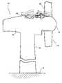
- FIG. 7is a partial perspective view of a hub and nacelle with cooling air inlet configuration in accordance with another exemplary embodiment
- FIG. 8is a perspective view of a cooling air inlet arrangement in the hub in accordance with still another exemplary embodiment
- FIG. 9is a fragmentary cross-section of the hub shown in FIG. 8 ;
- FIG. 10is a partial perspective view of a cooling air inlet in a hub in accordance with yet another embodiment of the invention.
- FIG. 1there is schematically illustrated a wind turbine generator, generally designated 10 , and including a rotating hub 12 mounting two or more airfoil shaped blades 14 , a fixed nacelle 16 and a pylon 18 for structurally supporting the wind turbine generator hundreds of feet above ground level G.
- the nacelle 16mounts a plurality of coils, or windings 22 forming part of the stator and a plurality of magnets or poles 24 about the rotor adjacent a forward part of the rotor near the hub 12 .
- the illustrated present embodimentincludes a double-sided generator having, as part of the stator, inner stator coils 22 and outer stator coils 26 and, as part of the rotor, outer magnets or poles 24 and inner magnets or poles 28 .
- the wind driven blades 14drive the hub 12 which, in turn, rotates the outer and inner magnets 24 and 28 relative to the outer and inner stator coils 26 and 22 to generate electricity.
- the inner and outer stator coils 22 and 26respectively constitute generally elliptically or oval shaped coils spaced circumferentially one from the other about the generator stator.
- the stator coilsare also mounted on a yolk 30 fixed to the nacelle 16 .
- the cooling systemincludes a plurality of air intakes 44 , three being shown in FIG. 2 .
- the intakes 44constitute pipes for transmitting air received in an inlet 46 ( FIG. 1 ) opening along the surface of the nacelle 16 .
- three inlets 46are circumferentially spaced one from the other about the nacelle, for example about 120 degrees apart for receiving air passing over the nacelle 16 .
- the inletssuction a part of the boundary layer flow forward of the inlets for transmission along the pipes 44 to an inlet manifold 50 ( FIG. 3 ).
- Manifold 50comprises an annulus of similar diameter as the stator coils and is spaced behind the inner and outer stator coils 22 and 26 .
- the manifold 50may be continuous or segregated into compartments of equal circumferential lengths for providing cooling air to an associated segment of the stator coils axially forwardly of the inlet manifold 50 . Since the flow of inlet air per se is not sufficient to maintain the generator in a cooled condition, the inlet air flow is augmented by blowers 52 ( FIG. 2 ) disposed in the pipes 44 in advance of the inlet manifold 50 .
- Various filters 54are also placed in the inlet pipes 44 .
- a plurality of circumferentially spaced outlets 55each including an exhaust pipe 56 and an exhaust collar, collectively called an exhaust can 58 .
- An annular generally C-shaped channel 60overlies the exhaust can 58 on the outlet side of the cans 58 .
- the base of the channel 60is spaced from and overlies the exhaust outlets of the exhaust pipe 56 .
- Channel 60also has free side edges spaced axially from the forward face of the rotating component providing generally radially extending heated cooling air exhaust passages 59 .
- the cooling system illustrated in FIGS. 1-5may be characterized as a front exit system.
- Such systemhas various advantages.
- the components of the systemare enclosed within the nacelle and are thus protected from outside elements.
- the generator elements, e.g., the rotor coils 22 , 26can be easily replaced.
- the C-shaped channelalso not only protects the individual exhaust pipes and collars but diverts the exiting flow back towards the nacelle.
- An annular flow director 58is illustrated in FIG. 1 to facilitate airflow over the step in the rotor between the hub and the magnetic poles.
- the air exiting the C-shaped channelis essentially sucked from the channel to join the boundary layer flow along the outer surface of the nacelle.
- cooling airenters through entry ports 68 along the front face of the annular compartment 70 housing the stator coils to cool the stator coils substantially by air flow in the reverse direction than the direction of air flow in the previous embodiment.
- the heated air from the cooling flow about the stator coils 22 , 26constitutes a rear exit approach using the pressure head due to the wind at the entry ports 68 .
- one or more of a blower, internal vented laminations and an encased external fanmay be used to assist the cooling air flow.
- blowers 72may augment the passage of air from the front entry ports to the rear exit port 75 .
- FIGS. 7-10Variations of the above described cooling inlet configurations are disclosed in FIGS. 7-10 .
- blade root and nacelle ductsare employed to ingest wind air for nacelle and hub cooling. More specifically, the blade roots 74 , where the blades are attached to the hub 76 , are each provided with a duct 78 (one shown) with an inlet opening 80 facing forward (upstream of the nacelle 82 ). The duct 78 feeds ingested wind air into a hub duct 84 that, in turn feeds cooling air to the annular manifold or plenum 70 as described in connection with FIG. 6 .
- Additional cooling wind airmay be ingested via nacelle scoops 86 that also open in a forward direction.
- the number of scoops 86may be varied about the periphery of the nacelle, but with preferably in a symmetrical array.
- the array in FIG. 7includes four such scoops (three shown).
- Scoops 86feed the cooling air through cooling air intake holes 88 in the nacelle wall to join the cooling air entering the blade root ducts flowing to the manifold or plenum 70 .
- FIGS. 8 and 9illustrate a hub 90 formed with three hub ducts 92 (two shown), located circumferentially between the blade roots 93 .
- Each hub ducthas a forwardly facing inlet opening 94 .
- Each ductmaybe provided with a filter 96 at the inlet opening, as well as a plurality of internal baffles 98 arranged to form a serpentine flow path for the cooling air.
- the ninety degree bends in the flow pathhelps remove moisture from the air prior to entering the annular chamber 70 .
- the cooling airwill exit the nacelle 100 via rear exit vents 102 (one shown in phantom).
- FIG. 10illustrates a hub 104 provided with a single forwardly-facing air intake 106 in the center of the hub.
- the cooling airflows through internal openings 108 between the blade root holes 110 and into the nacelle and the annular chamber 70 .
Landscapes
- Engineering & Computer Science (AREA)
- Life Sciences & Earth Sciences (AREA)
- Sustainable Energy (AREA)
- Sustainable Development (AREA)
- Power Engineering (AREA)
- Mechanical Engineering (AREA)
- Chemical & Material Sciences (AREA)
- Combustion & Propulsion (AREA)
- General Engineering & Computer Science (AREA)
- Thermal Sciences (AREA)
- Physics & Mathematics (AREA)
- Motor Or Generator Cooling System (AREA)
- Wind Motors (AREA)
Abstract
Description
Claims (12)
Priority Applications (5)
| Application Number | Priority Date | Filing Date | Title |
|---|---|---|---|
| US11/385,730US7427814B2 (en) | 2006-03-22 | 2006-03-22 | Wind turbine generators having wind assisted cooling systems and cooling methods |
| DK07100847.8TDK1837519T3 (en) | 2006-03-22 | 2007-01-19 | Wind turbine generators with wind assisted cooling systems and cooling methods |
| EP07100847.8AEP1837519B1 (en) | 2006-03-22 | 2007-01-19 | Wind turbine generators having wind assisted cooling systems and cooling methods |
| ES07100847.8TES2591234T3 (en) | 2006-03-22 | 2007-01-19 | Wind turbine generators that have assisted cooling systems and cooling procedures |
| CN2007100860436ACN101042114B (en) | 2006-03-22 | 2007-01-22 | Wind turbine generators having wind assisted cooling systems and cooling methods |
Applications Claiming Priority (1)
| Application Number | Priority Date | Filing Date | Title |
|---|---|---|---|
| US11/385,730US7427814B2 (en) | 2006-03-22 | 2006-03-22 | Wind turbine generators having wind assisted cooling systems and cooling methods |
Publications (2)
| Publication Number | Publication Date |
|---|---|
| US20070222223A1 US20070222223A1 (en) | 2007-09-27 |
| US7427814B2true US7427814B2 (en) | 2008-09-23 |
Family
ID=38261587
Family Applications (1)
| Application Number | Title | Priority Date | Filing Date |
|---|---|---|---|
| US11/385,730Active2026-08-15US7427814B2 (en) | 2006-03-22 | 2006-03-22 | Wind turbine generators having wind assisted cooling systems and cooling methods |
Country Status (5)
| Country | Link |
|---|---|
| US (1) | US7427814B2 (en) |
| EP (1) | EP1837519B1 (en) |
| CN (1) | CN101042114B (en) |
| DK (1) | DK1837519T3 (en) |
| ES (1) | ES2591234T3 (en) |
Cited By (41)
| Publication number | Priority date | Publication date | Assignee | Title |
|---|---|---|---|---|
| US20080025847A1 (en)* | 2006-07-31 | 2008-01-31 | Ewald Teipen | Ventilation assembly for wind turbine rotor hub |
| US20080197638A1 (en)* | 2004-09-24 | 2008-08-21 | Aloys Wobben | Wind Turbine Comprising a Generator Cooling System |
| US20080247875A1 (en)* | 2007-04-06 | 2008-10-09 | Fuji Jukogyo Kabushiki Kaisha | Horizontal axis wind turbine |
| US20080315594A1 (en)* | 2001-09-13 | 2008-12-25 | High Technology Investments, Bv | Wind power generator and bearing structure therefor |
| US20090074566A1 (en)* | 2007-09-17 | 2009-03-19 | Wen-Wei Chang | Wind power generating device |
| US20100127502A1 (en)* | 2008-07-28 | 2010-05-27 | Takashi Uchino | Wind turbine generator system |
| US20100133824A1 (en)* | 2009-09-25 | 2010-06-03 | General Electric Company | Method and system for cooling a wind turbine structure |
| US20100164228A1 (en)* | 2009-07-09 | 2010-07-01 | Mitsubishi Heavy Industries , Ltd. | Wind turbine generator |
| WO2010097948A1 (en) | 2009-02-27 | 2010-09-02 | 三菱重工業株式会社 | Wind driven generator |
| US20110062720A1 (en)* | 2008-05-13 | 2011-03-17 | Suzlon Energy Gmbh | Control box for a wind turbine |
| US20110140552A1 (en)* | 2010-09-29 | 2011-06-16 | General Electric Company | Cooling structure for a segmented stator assembly |
| US20110142618A1 (en)* | 2010-10-29 | 2011-06-16 | Bradley Graham Moore | Wind turbine pitch assembly enclosure system |
| US20110140444A1 (en)* | 2010-10-16 | 2011-06-16 | Winter Curt B | Wind Turbine With Improved Cooling |
| US20110221204A1 (en)* | 2008-09-01 | 2011-09-15 | Doosan Heavy Industries & Construction Co., Ltd. | Nacelle cooling system for wind turbine |
| US20110241353A1 (en)* | 2011-01-28 | 2011-10-06 | Mitsubishi Heavy Industries, Ltd. | Wind turbine generator |
| US20120001437A1 (en)* | 2010-06-30 | 2012-01-05 | Mitsubishi Heavy Industries, Ltd. | Wind power generator |
| US8120198B2 (en) | 2008-07-23 | 2012-02-21 | Wilic S.Ar.L. | Wind power turbine |
| US20120148407A1 (en)* | 2011-08-10 | 2012-06-14 | Mitsubishi Heavy Industries, Ltd. | Wind turbine generator |
| US8272822B2 (en) | 2009-01-30 | 2012-09-25 | Wilic S.Ar.L. | Wind power turbine blade packing and packing method |
| US8274170B2 (en) | 2009-04-09 | 2012-09-25 | Willic S.A.R.L. | Wind power turbine including a cable bundle guide device |
| US8319362B2 (en) | 2008-11-12 | 2012-11-27 | Wilic S.Ar.L. | Wind power turbine with a cooling system |
| US8358189B2 (en) | 2009-08-07 | 2013-01-22 | Willic S.Ar.L. | Method and apparatus for activating an electric machine, and electric machine |
| US8410623B2 (en) | 2009-06-10 | 2013-04-02 | Wilic S. AR. L. | Wind power electricity generating system and relative control method |
| US20130140829A1 (en)* | 2011-12-02 | 2013-06-06 | Gamesa Innovation & Technology., S.L., | Nacelle thermal conditioning system for off-shore wind turbines |
| US8492919B2 (en)* | 2008-06-19 | 2013-07-23 | Wilic S.Ar.L. | Wind power generator equipped with a cooling system |
| US8541902B2 (en) | 2010-02-04 | 2013-09-24 | Wilic S.Ar.L. | Wind power turbine electric generator cooling system and method and wind power turbine comprising such a cooling system |
| US8618689B2 (en) | 2009-11-23 | 2013-12-31 | Wilic S.Ar.L. | Wind power turbine for generating electric energy |
| US8659867B2 (en) | 2009-04-29 | 2014-02-25 | Wilic S.A.R.L. | Wind power system for generating electric energy |
| US8669685B2 (en) | 2008-11-13 | 2014-03-11 | Wilic S.Ar.L. | Wind power turbine for producing electric energy |
| US8876483B2 (en) | 2010-01-14 | 2014-11-04 | Neptco, Inc. | Wind turbine rotor blade components and methods of making same |
| US8937398B2 (en) | 2011-03-10 | 2015-01-20 | Wilic S.Ar.L. | Wind turbine rotary electric machine |
| US8937397B2 (en) | 2010-03-30 | 2015-01-20 | Wilic S.A.R.L. | Wind power turbine and method of removing a bearing from a wind power turbine |
| US8957555B2 (en) | 2011-03-10 | 2015-02-17 | Wilic S.Ar.L. | Wind turbine rotary electric machine |
| US8975770B2 (en) | 2010-04-22 | 2015-03-10 | Wilic S.Ar.L. | Wind power turbine electric generator and wind power turbine equipped with an electric generator |
| US9006918B2 (en) | 2011-03-10 | 2015-04-14 | Wilic S.A.R.L. | Wind turbine |
| US9077212B2 (en) | 2010-09-23 | 2015-07-07 | Northern Power Systems, Inc. | Method and apparatus for rotor cooling in an electromechanical machine |
| US9631607B2 (en) | 2008-10-08 | 2017-04-25 | Aloys Wobben | Ring generator |
| US10137542B2 (en) | 2010-01-14 | 2018-11-27 | Senvion Gmbh | Wind turbine rotor blade components and machine for making same |
| US11146143B2 (en)* | 2017-11-08 | 2021-10-12 | Siemens Gamesa Renewable Energy A/S | Operating a wind turbine generator cooling system |
| US11493027B2 (en)* | 2017-12-17 | 2022-11-08 | Vestas Wind Systems A/S | Wind turbine nacelle cooling |
| US20230033170A1 (en)* | 2021-07-27 | 2023-02-02 | General Electric Renovables Espana, S.L. | Cooling of active elements of electrical machines |
Families Citing this family (50)
| Publication number | Priority date | Publication date | Assignee | Title |
|---|---|---|---|---|
| DE102007003618A1 (en)* | 2007-01-18 | 2008-07-24 | Voith Patent Gmbh | Power generation plant driven by a wind or water flow |
| ES2350271T3 (en)* | 2007-02-14 | 2011-01-20 | Vestas Wind Systems A/S | AIR RECIRCULATION SYSTEM IN A COMPONENT OF A WIND TURBINE. |
| JP4898621B2 (en)* | 2007-10-05 | 2012-03-21 | 三菱重工業株式会社 | Wind power generator |
| US7997855B2 (en) | 2008-01-29 | 2011-08-16 | General Electric Company | Lubrication heating system and wind turbine incorporating same |
| US20090200114A1 (en)* | 2008-02-08 | 2009-08-13 | General Electric Company | Thermal management system and wind turbine incorporating same |
| JP2009250214A (en)* | 2008-04-10 | 2009-10-29 | Mitsubishi Heavy Ind Ltd | Fan device for wind-driven electric power generation device and wind-driven electric power generation device |
| TWM346265U (en)* | 2008-05-08 | 2008-12-01 | Asia Vital Components Co Ltd | Heat dissipation structure |
| WO2010022724A2 (en) | 2008-08-28 | 2010-03-04 | Vestas Wind Systems A/S | Filtering of debris in wind turbines |
| US8047774B2 (en)* | 2008-09-11 | 2011-11-01 | General Electric Company | System for heating and cooling wind turbine components |
| JP2012503971A (en)* | 2008-09-23 | 2012-02-09 | エアロヴァイロンメント インコーポレイテッド | Stator winding heat sink configuration |
| CN102301135A (en)* | 2009-01-30 | 2011-12-28 | 维斯塔斯风力系统集团公司 | Wind turbine nacelle with cooler top |
| EP2213877A3 (en)* | 2009-01-30 | 2016-08-10 | Vestas Wind Systems A/S | Wind turbine having a Nacelle with cooler top |
| JP5455508B2 (en)* | 2009-08-28 | 2014-03-26 | 三菱重工業株式会社 | Wind turbine for wind power generation |
| NO20092984A1 (en)* | 2009-09-11 | 2011-02-14 | Blaaster Wind Tech As | Wind turbine |
| CN101649819B (en)* | 2009-09-18 | 2011-04-27 | 湘电风能有限公司 | Air switching system of directly-driven wind power generator |
| DE102010000756A1 (en)* | 2010-01-08 | 2011-07-14 | Wobben, Aloys, 26607 | Wind turbine |
| US9140233B2 (en)* | 2010-02-02 | 2015-09-22 | Garden Energy, Inc. | Wind power generation system |
| CN101793236B (en)* | 2010-04-16 | 2012-09-05 | 湘电风能有限公司 | Wind guide device of direct-drive wind power generator |
| CN101834490B (en)* | 2010-05-04 | 2013-07-17 | 浙江尔格科技有限公司 | Cooler of wind power generator |
| JP5463218B2 (en)* | 2010-06-30 | 2014-04-09 | 三菱重工業株式会社 | Wind power generator |
| DE102010043435A1 (en)* | 2010-11-04 | 2012-05-10 | Aloys Wobben | Wind turbine |
| US8421264B2 (en)* | 2010-11-14 | 2013-04-16 | Asia Vital Components Co., Ltd. | Wind power generation device for electronic equipment |
| WO2012111532A1 (en)* | 2011-02-15 | 2012-08-23 | 三菱重工業株式会社 | Wind power generation apparatus |
| JP5449235B2 (en)* | 2011-02-25 | 2014-03-19 | 三菱重工業株式会社 | Wind power generator |
| ITMI20110376A1 (en) | 2011-03-10 | 2012-09-11 | Wilic Sarl | FLUID COOLED AIRBRUSHER |
| KR101312952B1 (en) | 2011-08-11 | 2013-10-14 | 삼성중공업 주식회사 | Nacelle for wind generator and wind generator having the same |
| US20140110947A1 (en)* | 2012-10-24 | 2014-04-24 | Vestas Wind Systems A/S | Wind turbine generator having an eddy current brake, wind turbine having such a generator, and associated methods |
| CN103490558B (en)* | 2013-09-18 | 2016-07-06 | 江苏金风科技有限公司 | Direct wind-driven generator cooling system |
| EP2902619B1 (en)* | 2014-01-29 | 2018-01-17 | Siemens Aktiengesellschaft | Cooling arrangement for a direct drive wind turbine |
| EP3001028B1 (en)* | 2014-09-23 | 2020-02-19 | Nordex Energy GmbH | Spinner for a rotor hub |
| CN106677989A (en)* | 2015-11-06 | 2017-05-17 | 优利康达(天津)科技有限公司 | Wind generating set with self-cooling function |
| CN105863953B (en)* | 2016-03-24 | 2019-01-11 | 北京金风科创风电设备有限公司 | Wind turbine blades, wind turbine cooling devices and wind turbines |
| DK3279469T3 (en)* | 2016-08-05 | 2020-05-25 | Siemens Gamesa Renewable Energy As | Wind turbine with improved cooling of the generator and method of cooling the generator of a wind turbine |
| US20180038351A1 (en)* | 2016-08-05 | 2018-02-08 | Siemens Aktiengesellschaft | Wind turbine with improved cooling |
| CN106194609B (en)* | 2016-08-29 | 2019-11-19 | 优利康达(天津)科技有限公司 | A kind of cooling cabin certainly |
| US11891985B2 (en)* | 2017-04-24 | 2024-02-06 | Siemens Gamesa Renewable Energy A/S | Filter system for providing air into a generator of a wind turbine |
| CN111356838B (en)* | 2017-11-20 | 2022-11-25 | 远景能源(丹麦)有限公司 | Wind power generator and its nacelle, air filtration system and air filtration method |
| CN108361158A (en)* | 2018-01-30 | 2018-08-03 | 内蒙古久和能源装备有限公司 | A kind of kuppe air inlet wing plate rain-proof dust-proof structure and wind power generating blade wheel assembly |
| EP3584910B1 (en)* | 2018-06-19 | 2021-09-15 | Siemens Mobility GmbH | Electrical machine with improved discharge of thermal losses |
| DK3719313T3 (en)* | 2019-04-05 | 2024-08-12 | Siemens Gamesa Renewable Energy As | COOLING DEVICE FOR A WINDMILL |
| CN111864991B (en) | 2019-04-30 | 2024-02-23 | 金风科技股份有限公司 | Cooling system, motor and wind generating set |
| EP3772160A1 (en)* | 2019-07-31 | 2021-02-03 | General Electric Renovables España S.L. | A stator structure |
| DE102021107905A1 (en)* | 2021-03-29 | 2022-09-29 | Wobben Properties Gmbh | Air cooling device, generator, air guiding device, wind turbine and method for producing a generator and a wind turbine |
| PL4083413T3 (en)* | 2021-04-28 | 2024-08-19 | General Electric Renovables España S.L. | Back-up power supply for wind turbines |
| EP4125188A1 (en)* | 2021-07-26 | 2023-02-01 | General Electric Renovables España S.L. | Cooling of active elements of electrical machines |
| EP4124752B1 (en)* | 2021-07-28 | 2025-04-30 | Siemens Gamesa Renewable Energy A/S | Wind turbine canopy with cooling fluid outlet |
| EP4167448A1 (en) | 2021-10-15 | 2023-04-19 | Wobben Properties GmbH | Generator and wind turbine |
| EP4167449A1 (en) | 2021-10-15 | 2023-04-19 | Wobben Properties GmbH | Generator and wind turbine |
| CN116183840B (en)* | 2023-05-04 | 2023-06-30 | 四川交通职业技术学院 | Environment monitoring system for intelligent environmental protection engineering |
| CN117967532B (en)* | 2024-04-02 | 2024-06-11 | 国网山东省电力公司莱州市供电公司 | A heat dissipation device for a wind turbine |
Citations (13)
| Publication number | Priority date | Publication date | Assignee | Title |
|---|---|---|---|---|
| US1699949A (en)* | 1925-12-30 | 1929-01-22 | Herbert E Bucklen | Wind-driven generator |
| US2305256A (en)* | 1941-04-07 | 1942-12-15 | Champion Aviat Products Compan | Generator control |
| US4740711A (en)* | 1985-11-29 | 1988-04-26 | Fuji Electric Co., Ltd. | Pipeline built-in electric power generating set |
| US4767939A (en)* | 1987-06-09 | 1988-08-30 | Calley David G | Wind driven electric current producer |
| US6278197B1 (en)* | 2000-02-05 | 2001-08-21 | Kari Appa | Contra-rotating wind turbine system |
| US20010035651A1 (en)* | 2000-04-28 | 2001-11-01 | Toshiyuki Umemoto | Wind power generating device |
| US6676122B1 (en)* | 1999-07-14 | 2004-01-13 | Aloys Wobben | Wind energy facility with a closed cooling circuit |
| US20040041408A1 (en)* | 2002-06-28 | 2004-03-04 | Matteo Casazza | Wind generator unit with high energy yield |
| US6903466B1 (en)* | 1999-09-01 | 2005-06-07 | Alstom | Wind-power generator pod constituted by the body of an electricity generator |
| US20050186076A1 (en)* | 2003-09-10 | 2005-08-25 | Christoph Hessel | Wind turbine with outer noise shell |
| US20060071575A1 (en)* | 2004-09-27 | 2006-04-06 | General Electric Company | Electrical machine with double-sided stator |
| US7154191B2 (en)* | 2004-06-30 | 2006-12-26 | General Electric Company | Electrical machine with double-sided rotor |
| US7154192B2 (en)* | 2004-09-27 | 2006-12-26 | General Electric Company | Electrical machine with double-sided lamination stack |
Family Cites Families (3)
| Publication number | Priority date | Publication date | Assignee | Title |
|---|---|---|---|---|
| JPS5865977A (en)* | 1981-10-14 | 1983-04-19 | Hitachi Ltd | Cooling mechanism for wind power generator |
| JP2005069082A (en)* | 2003-08-22 | 2005-03-17 | Fuji Heavy Ind Ltd | Wind turbine temperature control device |
| DE102004018758A1 (en)* | 2004-04-16 | 2005-11-03 | Klinger, Friedrich, Prof. Dr.-Ing. | Tower head of a wind turbine |
- 2006
- 2006-03-22USUS11/385,730patent/US7427814B2/enactiveActive
- 2007
- 2007-01-19ESES07100847.8Tpatent/ES2591234T3/enactiveActive
- 2007-01-19DKDK07100847.8Tpatent/DK1837519T3/enactive
- 2007-01-19EPEP07100847.8Apatent/EP1837519B1/enactiveActive
- 2007-01-22CNCN2007100860436Apatent/CN101042114B/enactiveActive
Patent Citations (14)
| Publication number | Priority date | Publication date | Assignee | Title |
|---|---|---|---|---|
| US1699949A (en)* | 1925-12-30 | 1929-01-22 | Herbert E Bucklen | Wind-driven generator |
| US2305256A (en)* | 1941-04-07 | 1942-12-15 | Champion Aviat Products Compan | Generator control |
| US4740711A (en)* | 1985-11-29 | 1988-04-26 | Fuji Electric Co., Ltd. | Pipeline built-in electric power generating set |
| US4767939A (en)* | 1987-06-09 | 1988-08-30 | Calley David G | Wind driven electric current producer |
| US6676122B1 (en)* | 1999-07-14 | 2004-01-13 | Aloys Wobben | Wind energy facility with a closed cooling circuit |
| US6903466B1 (en)* | 1999-09-01 | 2005-06-07 | Alstom | Wind-power generator pod constituted by the body of an electricity generator |
| US6278197B1 (en)* | 2000-02-05 | 2001-08-21 | Kari Appa | Contra-rotating wind turbine system |
| US6483199B2 (en)* | 2000-04-28 | 2002-11-19 | Mitsubishi Denki Kabushiki Kaisha | Wind power generating device |
| US20010035651A1 (en)* | 2000-04-28 | 2001-11-01 | Toshiyuki Umemoto | Wind power generating device |
| US20040041408A1 (en)* | 2002-06-28 | 2004-03-04 | Matteo Casazza | Wind generator unit with high energy yield |
| US20050186076A1 (en)* | 2003-09-10 | 2005-08-25 | Christoph Hessel | Wind turbine with outer noise shell |
| US7154191B2 (en)* | 2004-06-30 | 2006-12-26 | General Electric Company | Electrical machine with double-sided rotor |
| US20060071575A1 (en)* | 2004-09-27 | 2006-04-06 | General Electric Company | Electrical machine with double-sided stator |
| US7154192B2 (en)* | 2004-09-27 | 2006-12-26 | General Electric Company | Electrical machine with double-sided lamination stack |
Cited By (67)
| Publication number | Priority date | Publication date | Assignee | Title |
|---|---|---|---|---|
| US7687932B2 (en)* | 2001-09-13 | 2010-03-30 | High Technology Investments B.V. | Wind power generator and bearing structure therefor |
| US7893555B2 (en) | 2001-09-13 | 2011-02-22 | Wilic S.Ar.L. | Wind power current generator |
| US20080315594A1 (en)* | 2001-09-13 | 2008-12-25 | High Technology Investments, Bv | Wind power generator and bearing structure therefor |
| US20080197638A1 (en)* | 2004-09-24 | 2008-08-21 | Aloys Wobben | Wind Turbine Comprising a Generator Cooling System |
| US8053918B2 (en)* | 2004-09-24 | 2011-11-08 | Aloys Wobben | Wind turbine comprising a generator cooling system |
| US8552576B2 (en) | 2004-09-24 | 2013-10-08 | Aloys Wobben | Wind turbine comprising a generator cooling system |
| US20080025847A1 (en)* | 2006-07-31 | 2008-01-31 | Ewald Teipen | Ventilation assembly for wind turbine rotor hub |
| US7594800B2 (en)* | 2006-07-31 | 2009-09-29 | General Electric Company | Ventilation assembly for wind turbine rotor hub |
| US8235651B2 (en)* | 2007-04-06 | 2012-08-07 | Fuji Jikogyo Kabushiki Kaisha | Horizontal axis wind turbine including a rotating exhaust duct |
| US20080247875A1 (en)* | 2007-04-06 | 2008-10-09 | Fuji Jukogyo Kabushiki Kaisha | Horizontal axis wind turbine |
| US7547986B2 (en)* | 2007-09-17 | 2009-06-16 | Wen-Wei Chang | Wind power generating device |
| US20090074566A1 (en)* | 2007-09-17 | 2009-03-19 | Wen-Wei Chang | Wind power generating device |
| US20110062720A1 (en)* | 2008-05-13 | 2011-03-17 | Suzlon Energy Gmbh | Control box for a wind turbine |
| US9312741B2 (en) | 2008-06-19 | 2016-04-12 | Windfin B.V. | Wind power generator equipped with a cooling system |
| US8492919B2 (en)* | 2008-06-19 | 2013-07-23 | Wilic S.Ar.L. | Wind power generator equipped with a cooling system |
| US10505419B2 (en) | 2008-06-19 | 2019-12-10 | Windfin B.V. | Wind power generator equipped with a cooling system |
| US8120198B2 (en) | 2008-07-23 | 2012-02-21 | Wilic S.Ar.L. | Wind power turbine |
| US8109814B2 (en)* | 2008-07-28 | 2012-02-07 | Mitsubishi Heavy Industries, Ltd. | Wind turbine generator system |
| US20100127502A1 (en)* | 2008-07-28 | 2010-05-27 | Takashi Uchino | Wind turbine generator system |
| US8640478B2 (en)* | 2008-09-01 | 2014-02-04 | Doosan Heavy Industries & Construction Co., Ltd. | Nacelle cooling system for wind turbine |
| US20110221204A1 (en)* | 2008-09-01 | 2011-09-15 | Doosan Heavy Industries & Construction Co., Ltd. | Nacelle cooling system for wind turbine |
| US9631607B2 (en) | 2008-10-08 | 2017-04-25 | Aloys Wobben | Ring generator |
| US8319362B2 (en) | 2008-11-12 | 2012-11-27 | Wilic S.Ar.L. | Wind power turbine with a cooling system |
| US8669685B2 (en) | 2008-11-13 | 2014-03-11 | Wilic S.Ar.L. | Wind power turbine for producing electric energy |
| US8272822B2 (en) | 2009-01-30 | 2012-09-25 | Wilic S.Ar.L. | Wind power turbine blade packing and packing method |
| US20110175368A1 (en)* | 2009-02-27 | 2011-07-21 | Mitsubishi Heavy Industries, Ltd. | Wind driven generator |
| WO2010097948A1 (en) | 2009-02-27 | 2010-09-02 | 三菱重工業株式会社 | Wind driven generator |
| US8274170B2 (en) | 2009-04-09 | 2012-09-25 | Willic S.A.R.L. | Wind power turbine including a cable bundle guide device |
| US8659867B2 (en) | 2009-04-29 | 2014-02-25 | Wilic S.A.R.L. | Wind power system for generating electric energy |
| US8410623B2 (en) | 2009-06-10 | 2013-04-02 | Wilic S. AR. L. | Wind power electricity generating system and relative control method |
| US20100164228A1 (en)* | 2009-07-09 | 2010-07-01 | Mitsubishi Heavy Industries , Ltd. | Wind turbine generator |
| US8360715B2 (en)* | 2009-07-09 | 2013-01-29 | Mitsubishi Heavy Industries, Ltd. | Wind turbine generator |
| US8810347B2 (en) | 2009-08-07 | 2014-08-19 | Wilic S.Ar.L | Method and apparatus for activating an electric machine, and electric machine |
| US8358189B2 (en) | 2009-08-07 | 2013-01-22 | Willic S.Ar.L. | Method and apparatus for activating an electric machine, and electric machine |
| US7837126B2 (en) | 2009-09-25 | 2010-11-23 | General Electric Company | Method and system for cooling a wind turbine structure |
| US20100133824A1 (en)* | 2009-09-25 | 2010-06-03 | General Electric Company | Method and system for cooling a wind turbine structure |
| US8618689B2 (en) | 2009-11-23 | 2013-12-31 | Wilic S.Ar.L. | Wind power turbine for generating electric energy |
| US8876483B2 (en) | 2010-01-14 | 2014-11-04 | Neptco, Inc. | Wind turbine rotor blade components and methods of making same |
| US9394882B2 (en) | 2010-01-14 | 2016-07-19 | Senvion Gmbh | Wind turbine rotor blade components and methods of making same |
| US9429140B2 (en) | 2010-01-14 | 2016-08-30 | Senvion Gmbh | Wind turbine rotor blade components and methods of making same |
| US9945355B2 (en) | 2010-01-14 | 2018-04-17 | Senvion Gmbh | Wind turbine rotor blade components and methods of making same |
| US10137542B2 (en) | 2010-01-14 | 2018-11-27 | Senvion Gmbh | Wind turbine rotor blade components and machine for making same |
| US8541902B2 (en) | 2010-02-04 | 2013-09-24 | Wilic S.Ar.L. | Wind power turbine electric generator cooling system and method and wind power turbine comprising such a cooling system |
| US8937397B2 (en) | 2010-03-30 | 2015-01-20 | Wilic S.A.R.L. | Wind power turbine and method of removing a bearing from a wind power turbine |
| US8975770B2 (en) | 2010-04-22 | 2015-03-10 | Wilic S.Ar.L. | Wind power turbine electric generator and wind power turbine equipped with an electric generator |
| US8403638B2 (en)* | 2010-06-30 | 2013-03-26 | Mitsubishi Heavy Industries, Ltd. | Wind power generator |
| US20120001437A1 (en)* | 2010-06-30 | 2012-01-05 | Mitsubishi Heavy Industries, Ltd. | Wind power generator |
| US9077212B2 (en) | 2010-09-23 | 2015-07-07 | Northern Power Systems, Inc. | Method and apparatus for rotor cooling in an electromechanical machine |
| US20110140552A1 (en)* | 2010-09-29 | 2011-06-16 | General Electric Company | Cooling structure for a segmented stator assembly |
| US8456048B2 (en) | 2010-09-29 | 2013-06-04 | General Electric Company | Cooling structure for a segmented stator assembly |
| US7963743B1 (en) | 2010-10-16 | 2011-06-21 | Winter Curt B | Wind turbine with improved cooling |
| US20110140444A1 (en)* | 2010-10-16 | 2011-06-16 | Winter Curt B | Wind Turbine With Improved Cooling |
| US20110142618A1 (en)* | 2010-10-29 | 2011-06-16 | Bradley Graham Moore | Wind turbine pitch assembly enclosure system |
| US20110241353A1 (en)* | 2011-01-28 | 2011-10-06 | Mitsubishi Heavy Industries, Ltd. | Wind turbine generator |
| US8308434B2 (en)* | 2011-01-28 | 2012-11-13 | Mitsubishi Heavy Industries, Ltd. | Wind turbine generator |
| WO2012101817A1 (en)* | 2011-01-28 | 2012-08-02 | 三菱重工業株式会社 | Wind power generation device |
| US8937398B2 (en) | 2011-03-10 | 2015-01-20 | Wilic S.Ar.L. | Wind turbine rotary electric machine |
| US9006918B2 (en) | 2011-03-10 | 2015-04-14 | Wilic S.A.R.L. | Wind turbine |
| US8957555B2 (en) | 2011-03-10 | 2015-02-17 | Wilic S.Ar.L. | Wind turbine rotary electric machine |
| US20120148407A1 (en)* | 2011-08-10 | 2012-06-14 | Mitsubishi Heavy Industries, Ltd. | Wind turbine generator |
| US8632303B2 (en)* | 2011-08-10 | 2014-01-21 | Mitsubishi Heavy Industries, Ltd. | Wind turbine generator |
| US20130140829A1 (en)* | 2011-12-02 | 2013-06-06 | Gamesa Innovation & Technology., S.L., | Nacelle thermal conditioning system for off-shore wind turbines |
| US9062659B2 (en)* | 2011-12-02 | 2015-06-23 | Gamesa Innovation & Technology, S.L. | Nacelle thermal conditioning system for off-shore wind turbines |
| US11146143B2 (en)* | 2017-11-08 | 2021-10-12 | Siemens Gamesa Renewable Energy A/S | Operating a wind turbine generator cooling system |
| US11493027B2 (en)* | 2017-12-17 | 2022-11-08 | Vestas Wind Systems A/S | Wind turbine nacelle cooling |
| US20230033170A1 (en)* | 2021-07-27 | 2023-02-02 | General Electric Renovables Espana, S.L. | Cooling of active elements of electrical machines |
| US12021436B2 (en)* | 2021-07-27 | 2024-06-25 | General Electric Renovables Espana, S.L. | Cooling of active elements of electrical machines |
Also Published As
| Publication number | Publication date |
|---|---|
| DK1837519T3 (en) | 2016-09-12 |
| EP1837519B1 (en) | 2016-07-13 |
| US20070222223A1 (en) | 2007-09-27 |
| EP1837519A3 (en) | 2012-11-21 |
| EP1837519A2 (en) | 2007-09-26 |
| ES2591234T3 (en) | 2016-11-25 |
| CN101042114B (en) | 2012-06-13 |
| CN101042114A (en) | 2007-09-26 |
Similar Documents
| Publication | Publication Date | Title |
|---|---|---|
| US7427814B2 (en) | Wind turbine generators having wind assisted cooling systems and cooling methods | |
| CN108661865B (en) | Nacelle for a wind turbine comprising a cooling circuit | |
| DK2615299T3 (en) | Machine booth for a wind turbine | |
| CN1068409C (en) | Integrated steam/air cooling system for gas turbines | |
| JP2017120082A (en) | Method and system for compressor and turbine cooling | |
| US20170370284A1 (en) | Gas turbine engine | |
| CN105186783A (en) | Generator cooling arrangement | |
| CN108026931A (en) | With heat sink turbofan | |
| CN108730038A (en) | Method and system for cooling fluid distribution | |
| RU2433309C2 (en) | System to cool rear cavity of centrifugal compressor impeller | |
| KR20110065559A (en) | Turbine cooling system | |
| CN102124637A (en) | Rotating electrical machine | |
| AU2012226384A1 (en) | Fluid-cooled wind turbine | |
| WO2020042662A1 (en) | Wind power generator set, electromagnetic device, and heat exchange or drying device for iron core | |
| JP2005069082A (en) | Wind turbine temperature control device | |
| CN104806458A (en) | Cooling arrangement | |
| EP3279469B1 (en) | Wind turbine with improved cooling of the generator and method for cooling the generator of a wind turbine | |
| RU2196239C2 (en) | Turbojet engine turbine cooling system | |
| WO2020063074A1 (en) | Wind power generation unit, electic motor, and airflow delivery device for electric motor air gap | |
| WO2020052467A1 (en) | Stator assembly, motor having same and wind power generator set | |
| WO2020042574A1 (en) | Medium transport and heat exchange device of iron core of electromagnetic device, and eddy current separator | |
| US6914355B2 (en) | Common radial plane motor cooling | |
| CN109072699A (en) | With the cooling industrial gas turbine engine of first and second grades of rotors | |
| CN208330633U (en) | A kind of cooling wind diversion distribution device and box wind-driven generator | |
| CN116800005A (en) | Ventilating and radiating structure of air-cooled motor |
Legal Events
| Date | Code | Title | Description |
|---|---|---|---|
| AS | Assignment | Owner name:GENERAL ELECTRIC COMPANY, NEW YORK Free format text:ASSIGNMENT OF ASSIGNORS INTEREST;ASSIGNORS:BAGEPALLI, BHARAT;BARNES, GARY R.;GADRE, ANIRUDDHA D.;AND OTHERS;REEL/FRAME:017721/0154;SIGNING DATES FROM 20060310 TO 20060320 | |
| FEPP | Fee payment procedure | Free format text:PAYOR NUMBER ASSIGNED (ORIGINAL EVENT CODE: ASPN); ENTITY STATUS OF PATENT OWNER: LARGE ENTITY | |
| STCF | Information on status: patent grant | Free format text:PATENTED CASE | |
| CC | Certificate of correction | ||
| FPAY | Fee payment | Year of fee payment:4 | |
| FPAY | Fee payment | Year of fee payment:8 | |
| AS | Assignment | Owner name:UNITED STATES DEPARTMENT OF ENERGY, DISTRICT OF CO Free format text:CONFIRMATORY LICENSE;ASSIGNOR:GE WIND ENERGY LLC;REEL/FRAME:043975/0813 Effective date:20170907 | |
| MAFP | Maintenance fee payment | Free format text:PAYMENT OF MAINTENANCE FEE, 12TH YEAR, LARGE ENTITY (ORIGINAL EVENT CODE: M1553); ENTITY STATUS OF PATENT OWNER: LARGE ENTITY Year of fee payment:12 | |
| AS | Assignment | Owner name:GE INFRASTRUCTURE TECHNOLOGY LLC, SOUTH CAROLINA Free format text:ASSIGNMENT OF ASSIGNORS INTEREST;ASSIGNOR:GENERAL ELECTRIC COMPANY;REEL/FRAME:065727/0001 Effective date:20231110 |