US7427165B2 - Optical and electrical hybrid connector - Google Patents
Optical and electrical hybrid connectorDownload PDFInfo
- Publication number
- US7427165B2 US7427165B2US11/154,023US15402305AUS7427165B2US 7427165 B2US7427165 B2US 7427165B2US 15402305 AUS15402305 AUS 15402305AUS 7427165 B2US7427165 B2US 7427165B2
- Authority
- US
- United States
- Prior art keywords
- socket
- connector
- shaft
- optical
- electrical
- Prior art date
- Legal status (The legal status is an assumption and is not a legal conclusion. Google has not performed a legal analysis and makes no representation as to the accuracy of the status listed.)
- Expired - Fee Related
Links
- 230000003287optical effectEffects0.000titleclaimsabstractdescription105
- 239000000835fiberSubstances0.000claimsabstractdescription59
- 239000013307optical fiberSubstances0.000claimsabstractdescription34
- 238000007667floatingMethods0.000claimsabstractdescription31
- 238000003780insertionMethods0.000claimsabstractdescription27
- 230000037431insertionEffects0.000claimsabstractdescription26
- 230000002093peripheral effectEffects0.000claimsabstractdescription13
- 230000002441reversible effectEffects0.000claimsabstractdescription9
- 238000010168coupling processMethods0.000claimsdescription44
- 230000008878couplingEffects0.000claimsdescription43
- 238000005859coupling reactionMethods0.000claimsdescription43
- 239000000523sampleSubstances0.000claimsdescription32
- 230000005540biological transmissionEffects0.000claimsdescription5
- 238000005516engineering processMethods0.000claimsdescription5
- 230000036961partial effectEffects0.000claimsdescription2
- 230000013011matingEffects0.000description17
- 230000008901benefitEffects0.000description9
- 238000013461designMethods0.000description8
- 238000004519manufacturing processMethods0.000description6
- 230000006870functionEffects0.000description5
- 239000011521glassSubstances0.000description5
- 238000006073displacement reactionMethods0.000description4
- 230000000694effectsEffects0.000description3
- 238000002474experimental methodMethods0.000description3
- 238000005286illuminationMethods0.000description3
- 238000000034methodMethods0.000description3
- VYPSYNLAJGMNEJ-UHFFFAOYSA-NSilicium dioxideChemical compoundO=[Si]=OVYPSYNLAJGMNEJ-UHFFFAOYSA-N0.000description2
- 238000003491arrayMethods0.000description2
- 239000002184metalSubstances0.000description2
- 229910052751metalInorganic materials0.000description2
- 230000002829reductive effectEffects0.000description2
- 229910001220stainless steelInorganic materials0.000description2
- 239000010935stainless steelSubstances0.000description2
- RYGMFSIKBFXOCR-UHFFFAOYSA-NCopperChemical compound[Cu]RYGMFSIKBFXOCR-UHFFFAOYSA-N0.000description1
- 238000004026adhesive bondingMethods0.000description1
- 230000000712assemblyEffects0.000description1
- 238000000429assemblyMethods0.000description1
- 238000005253claddingMethods0.000description1
- 238000004140cleaningMethods0.000description1
- 239000013065commercial productSubstances0.000description1
- 229910052802copperInorganic materials0.000description1
- 239000010949copperSubstances0.000description1
- 230000007797corrosionEffects0.000description1
- 238000005260corrosionMethods0.000description1
- 230000001186cumulative effectEffects0.000description1
- 230000001419dependent effectEffects0.000description1
- 238000010348incorporationMethods0.000description1
- 238000001746injection mouldingMethods0.000description1
- 238000005304joiningMethods0.000description1
- 230000000670limiting effectEffects0.000description1
- 239000000463materialSubstances0.000description1
- 238000000968medical method and processMethods0.000description1
- 238000012806monitoring deviceMethods0.000description1
- 238000005457optimizationMethods0.000description1
- 238000005498polishingMethods0.000description1
- 230000001681protective effectEffects0.000description1
- 238000000926separation methodMethods0.000description1
- 239000000377silicon dioxideSubstances0.000description1
- 238000004611spectroscopical analysisMethods0.000description1
- 230000006641stabilisationEffects0.000description1
- 238000011105stabilizationMethods0.000description1
- 230000000087stabilizing effectEffects0.000description1
- 230000002459sustained effectEffects0.000description1
- 238000012546transferMethods0.000description1
- 230000003245working effectEffects0.000description1
Images


Classifications
- H—ELECTRICITY
- H01—ELECTRIC ELEMENTS
- H01R—ELECTRICALLY-CONDUCTIVE CONNECTIONS; STRUCTURAL ASSOCIATIONS OF A PLURALITY OF MUTUALLY-INSULATED ELECTRICAL CONNECTING ELEMENTS; COUPLING DEVICES; CURRENT COLLECTORS
- H01R24/00—Two-part coupling devices, or either of their cooperating parts, characterised by their overall structure
- H01R24/58—Contacts spaced along longitudinal axis of engagement
- G—PHYSICS
- G02—OPTICS
- G02B—OPTICAL ELEMENTS, SYSTEMS OR APPARATUS
- G02B6/00—Light guides; Structural details of arrangements comprising light guides and other optical elements, e.g. couplings
- G02B6/24—Coupling light guides
- G02B6/36—Mechanical coupling means
- G02B6/38—Mechanical coupling means having fibre to fibre mating means
- G02B6/3807—Dismountable connectors, i.e. comprising plugs
- G02B6/381—Dismountable connectors, i.e. comprising plugs of the ferrule type, e.g. fibre ends embedded in ferrules, connecting a pair of fibres
- G02B6/3817—Dismountable connectors, i.e. comprising plugs of the ferrule type, e.g. fibre ends embedded in ferrules, connecting a pair of fibres containing optical and electrical conductors
- G—PHYSICS
- G02—OPTICS
- G02B—OPTICAL ELEMENTS, SYSTEMS OR APPARATUS
- G02B6/00—Light guides; Structural details of arrangements comprising light guides and other optical elements, e.g. couplings
- G02B6/24—Coupling light guides
- G02B6/36—Mechanical coupling means
- G02B6/38—Mechanical coupling means having fibre to fibre mating means
- G02B6/3807—Dismountable connectors, i.e. comprising plugs
- G02B6/3897—Connectors fixed to housings, casing, frames or circuit boards
- H—ELECTRICITY
- H01—ELECTRIC ELEMENTS
- H01R—ELECTRICALLY-CONDUCTIVE CONNECTIONS; STRUCTURAL ASSOCIATIONS OF A PLURALITY OF MUTUALLY-INSULATED ELECTRICAL CONNECTING ELEMENTS; COUPLING DEVICES; CURRENT COLLECTORS
- H01R13/00—Details of coupling devices of the kinds covered by groups H01R12/70 or H01R24/00 - H01R33/00
- H01R13/02—Contact members
- H01R13/22—Contacts for co-operating by abutting
- H01R13/24—Contacts for co-operating by abutting resilient; resiliently-mounted
- H—ELECTRICITY
- H01—ELECTRIC ELEMENTS
- H01R—ELECTRICALLY-CONDUCTIVE CONNECTIONS; STRUCTURAL ASSOCIATIONS OF A PLURALITY OF MUTUALLY-INSULATED ELECTRICAL CONNECTING ELEMENTS; COUPLING DEVICES; CURRENT COLLECTORS
- H01R13/00—Details of coupling devices of the kinds covered by groups H01R12/70 or H01R24/00 - H01R33/00
- H01R13/62—Means for facilitating engagement or disengagement of coupling parts or for holding them in engagement
- H01R13/625—Casing or ring with bayonet engagement
- H—ELECTRICITY
- H01—ELECTRIC ELEMENTS
- H01R—ELECTRICALLY-CONDUCTIVE CONNECTIONS; STRUCTURAL ASSOCIATIONS OF A PLURALITY OF MUTUALLY-INSULATED ELECTRICAL CONNECTING ELEMENTS; COUPLING DEVICES; CURRENT COLLECTORS
- H01R2107/00—Four or more poles
Definitions
- the present inventionrelates to plug and socket connector systems for providing inexpensive, reversible, axial-position-error tolerant (Z-tolerant) mixed optical and electrical connections, and more particularly to a quick-insertion, non-shorting, rotationally-engaged, shaft and socket connector having one or more Z-tolerant float-coupled optical fibers located centrally inside an elongated shaft, and one or more Z-tolerant wide electrical contact array elements located peripherally on a flexible PC board mounted externally on the same shaft, for the purpose of creating reversible optical/electrical hybrid connections, thus avoiding much of the expense, awkwardness, and required axial precision inherent in conventional hybrid connector systems.
- Z-tolerantaxial-position-error tolerant
- the traditional optical or electrical connectoris a monolithic device, optimized for the delivery of a single signal type—either optical or electrical. There are reasons for this traditional separation of connectors by signal type. First, most applications require only one type of transmitted signal, and thus do not demand the additional design and materials expense involved in hybrid connections. Second, inherent features required for good electrical connections (e.g., good physical contact with contact element wiping, low axial positional mating accuracy, and no need of contact finishing after assembly) are different, and often contrary, to those features required for good optical fiber coupling (avoiding physical contact which damages fiber faces, high axial positional mating accuracy, and required post-assembly fiber-end finishing steps).
- Fiber connectionshave lateral (XY-axis) and axial (Z-axis) positional mating accuracy requirement as much as 1,000-fold more precise than for the above-described electrical connections.
- An optical fiber's tolerance for positional erroris typically very low for several inherent reasons.
- Second, a seemingly minor lateral positional misalignment of a pair of optical fiberstypically leads to huge fiber coupling losses. For illustration, a mere 0.004 inch lateral offset between a 100 micron pair of multimode fibers can lead to a complete loss of transmitted light.
- fiber connectionstypically require high-precision components in the connector. These precision components—including laser drilled ferrules and milled stainless-steel couplers—translate to a high connector cost.
- a pair of industry-standard SMA-type optical plugs and central mating dual-female coupler connectorallowing for the joining of only a single pair of fibers, retails at many times the price of a pair of 25-pin D-type electrical array male/female connectors.
- optical fiber ferrulesmust typically protrude beyond any protective holders in order to allow for fiber finishing (such as gluing, sanding, and polishing) after a new, bare optical connector is stuffed and glued with an optical fiber.
- Hybrid optical and electrical connectorsare known. Such deployments are most typically planar (XY-axis), in which the mating elements form a face that is flat and perpendicular to the axial mating axis.
- WO 01/042839 and U.S. Pat. No. 6,612,857teach independent detachable electrical or optical assemblies that are combined into a single hybrid connector.
- U.S. Pat. No. 6,599,025teaches a hybrid with the optical fiber positioned between the electrical elements of a standard connector.
- U.S. Pat. No. 6,588,938teaches a hybrid housing with planar arrays of electrical contact maintained by springs.
- Axial (Z-axis) deployment of the electrical contacts along a shaftis a known, though uncommon, alternative to planar contact deployment.
- U.S. Pat. No. 4,080,040teaches a longitudinal (axial) arrangement of multiple electrical contact elements along a patch-cord plug and receiving jack, but does not teach how to reduce the axial positional accuracy requirements of the connector through use of floating or lens-coupled elements for fibers in a hybrid design. Combination of this or other axial plug and socket arrangements with optical fibers, as is taught in the cited hybrid connectors above, would be insufficient to achieve Z-tolerance, as a need for Z-tolerant elements to increase axial tolerance is neither taught nor suggested in either body of art.
- None of the above systemssuggest or teach efficiently combining optical and electrical contacts into a single hybrid connector device optimized for both electrical and optical connections with both (a) a Z-tolerant coupling for the optical elements, and (b) a Z-tolerant coupling for an axial electrical array, together resulting in a low-cost of manufacture, ease of assembly, and single connector ease-of-use.
- a hybrid electrical and optical shaft and socket connector incorporating a Z-tolerant axial electrical array integrated with a Z-tolerant floating or lens-coupled fiber arrayhas not been taught or suggested, nor to our knowledge has such a tool been previously successfully manufactured and commercialized.
- the present inventionrelies upon the knowledge of design considerations needed to achieve a hybrid plug and socket connector with a Z-tolerant central floating optical fiber coupler and a Z-tolerant axial peripheral electrical contact array, allowing for rapid, inexpensive, axial-position-tolerant, self-wiping, reliable connections between connector elements, so as to provide an improved connection.
- the benefitsinclude rapid connection, rapid disconnection, low-cost, disposability, reproducibility, and reliability. This allows the implementation of medical monitors and probes more simply and inexpensively than has been achieved using commercially available connectors.
- a salient feature of the present inventionis that, while both electrical and optical connectors have different positional-accuracy mating requirements, the concurrent use of (a) a Z-tolerant, axially deployed, wide contact, peripheral electrical contact array and (b) a Z-tolerant floating central fiber core allows the differing mating requirements to be reliably and simultaneously satisfied.
- the floating optical core fiberis self-aligning, self-centering, axially-position-tolerant, and highly stable and reproducible.
- the floating componenttakes up Z-axis positional inaccuracies while maintaining absolute control over the distance between the coupled fiber faces. More than one fiber can be used.
- the linear electrical arrayallows broad, self-wiping, non-shorting, physical contact areas which are themselves Z-tolerant, without the high-mating-requirements typically demanded by optical matings.
- Thissubstantially lowers the cost of the electrical connectors, while maintaining expandability of 1 to N non-shorting quick-connect contacts.
- such wide contactscan be molded or provided by a flexible PC board very inexpensively, making the entire connector, and in particular the plug portion, manufacturable at very low cost.
- an object of the present inventionis to provide a Z-tolerant hybrid connector using a wide-electrical-contact array peripherally and circumferentially deployed around a central fiber core, which is itself Z-tolerant due to lens or float coupling.
- the fiber corehas only one fiber coupled using an axial floating coupler, and at least two wide peripheral electrical contacts, but this may be expanded to add additional optical fibers and electrical contacts as needed.
- some of the electrical contactsmay be replaced or supplemented by non-contact ID chips (such as the emerging Radio Frequency Identification (“RFID”) standard chip sets) that do not require a direct connection.
- RFIDRadio Frequency Identification
- Another objectis to provide a non-shorting electrical contact array with good physical contact that is engaged and wiped by rotation of the plug after insertion into the socket, enabling use with sensitive electronics or high-power applications.
- Another objectis to provide for a high-precision stabilization of the optical connections, which are stabilized by a locking action with partial rotation of the plug shaft.
- Another objectis to provide for a reversible quick-connection, with connection occurring in less than one full turn of a plug shaft, and preferably latching in one-fourth clockwise turn. This in turn allows for natural quick attachment and also permits quick disconnection, with disconnection occurring again in less than one full turn of the shaft, and preferably in one-fourth counterclockwise turn.
- Another objectis to provide for probes and systems with integrated connector systems, allowing for improved medical spectroscopic devices.
- a final objectis to provide for a connector with embedded identification and data, such as probe type, for example via EEPROM accessible across the connectors electrical connections, or even by non-contact functions, such as the RFID chips used in proximity tags and non-contract identity badges.
- the improved hybrid connector as describedhas multiple advantages.
- One advantageis that devices with both electrical and optical connections can be attached or disconnected using a single connector.
- Another advantageis that a centered fiber with coupling ferrule or coupling channel is self-aligning, and allows incorporation of Z-tolerant optical coupling techniques, such as transfer or collimating lenses and elements, floating couplers, and the like.
- Another advantageis that this attachment can occur reversibly, rapidly, and reliably.
- Another advantageis that the costly parts (the precision, floating alignment tube into which a shaft ferrule fits or a reverse collimating lens) can be placed into the socket connector, while the male plug shaft has only printed-circuit or card edge contacts, and low-tolerance optical ferrules, which are inexpensive compared to individual electrical contacts and precision optical connectors, thus reducing the cumulative cost of deployment of these connectors.
- a further advantageis that the electrical connection can be expanded as to any number of contacts, simply by increasing the length of the inserted shaft, reducing the spacing of the contacts, or adding additional parallel electrical array contact rows.
- the Z-tolerant connectorfor providing a reliable, rapid, unified, and reversible connection for mixed electrical and optical connections, specifically in the examples shown for the purpose of enabling spectroscopic analysis in human patients in real time.
- the Z-tolerant connectoruses an axial plug with a semi-circumferential-element linear electrical contact array deployed axially along its long axis, with central fiber and optical connection elements.
- a floating axial positionally tolerant floating couplerallows the fiber coupling to maintain a high internal axial accuracy with an inexpensive low axial-accuracy plug shaft.
- the plugmates reversibly to a socket containing a keyed channel into which the plug's shaft is fully inserted and then rotated.
- a turn of the plug shaftmates the electrical pads on the plug shaft with the spring contacts in the hollow channel of the socket, as well as stabilizing and securing the plug. Removal is achieved by rotation in the opposite direction, breaking the electrical contacts and allowing the plug to be removed from the hollow channel. Medical probes and systems incorporating the improved connector are also described.
- FIG. 1Ais an exploded perspective view of a plug and socket in accordance with the present invention.
- FIG. 1Bis an enlarged view of the spring loaded contacts in the socket of FIG. 1A ;
- FIG. 2is a perspective view of the plug
- FIG. 3Ais a perspective view partly in section showing the plug as it is inserted and seated into the socket;
- FIG. 3Bis an enlarged view of a portion of the inserted plug and socket of FIG. 3A ;
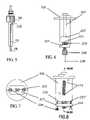
- FIG. 4is a front view of the plug
- FIG. 5is a side view of the plug showing the guiding and locking channel
- FIG. 6is a plan view of the socket
- FIG. 7is a rear view of the socket
- FIG. 8is a plan view of the socket showing the contact pins
- FIGS. 9A and 9Bare sectional perspective views illustrating insertion and rotation of the plug
- FIG. 10is a sectional view showing the plug inserted into the socket
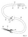
- FIG. 11shows a medical probe incorporating the Z-tolerant hybrid connector of FIGS. 1-10 ;
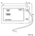
- FIG. 12shows a medical monitor incorporating the Z-tolerant hybrid connector of FIGS. 1-10 to which the probe of FIG. 11 is attached to form a complete medical system;
- FIG. 13Ais a graph showing a plateau of Z-tolerant connections, the ability of using a floating optical connection designed in accordance with the present invention.
- FIG. 13Bis a graph showing a plateau of Z-tolerant connections, the ability of using a coupling lens element designed in accordance with the present invention.
- Hybrid ConnectorA connector that contains both optical and electrical transmission lines to be coupled. Also called a Mixed Connector.
- PlugThe elongated, shaft-like member of the connector. Also called a Male Plug or Shaft.
- SocketThe hollow, receiving-chamber member of the connector, to which the Plug member is coupled by insertion of the plug into the receptacle. Also called a Female Socket, Receptacle, or Chamber.
- PeripheralLocated on or near the outer surface of the plug shaft, or along the inner chamber surface of the socket receptacle.
- peripheral contactsinclude an array of electrical pad elements located circumferentially on the surface of a rod-shaped plug, or a linear card edge located near the surface of a rod-shaped plug (c.f. central).
- CentralLocated at the inner or central region, not peripherally.
- the coreis toward the center of the shaft; for a socket, the core is located toward the axial central portion of the space in the socket chamber (c.f. peripheral).
- AxialAlong the long axis of an elongated member or connector insertion path. Also called the Z-Axis (c.f., planar).
- PlanarLocated perpendicular to the long axis of an elongated member or connector insertion path. Also called the X-Y axis.
- Z-Tolerant or Axially Position-TolerantAn element for which proper operation or coupling is not highly dependent upon an exact position of the inserted plug relative to a receptacle socket in the axial (Z-axis) direction.
- Axial ArrayA set of at least two contact elements deployed axially, for example a linear row of electrical contact pads are each deployed circumferentially at different fixed distances along the length of the shaft of a plug (c.f., planar array, below).
- Planar or X-Y ArrayA set of at least two contact elements deployed in a plane perpendicular to the insertable plug face.
- An example of an X-Y arrayis a conventional computer D-pin array, in which the elements are arrayed in rows and columns along a flat plug and socket face.
- a circumferential elementmay be a circular ring (fully circumferential), or an open ring or short arc (semi-circumferential).
- a semi-circumferential ring, pad, or arc shaped elementonly partially encircles the rod, shaft, or chamber.
- Rotationally EngagedA connector that is rotated in order to lock the probe and/or engage one or more sets of contacts.
- Optical CouplingThe arrangement of two optical elements such that light exiting the first element interacts, at least in part, with the second optical element. This may be free-space (unaided) transmission through air or space, or may require use of intervening, fixed or floating optical elements such as lenses, filters, fused fiber expanders, collimators, concentrators, collectors, optical fibers, prisms, mirrors, or mirrored surfaces.
- Electrical CouplingThe arrangement of two electrical elements such that the two elements can electrically interact and, in most cases, useable current can flow between them.
- the Z-tolerant optical coupling elementis a spring-loaded floating coupler that physically moves axially to allow for a high-precision coupling of two or more optical fibers, while allowing for tolerance of significant variance in the axial position of one fiber to the other, thus enabling a quality optical coupling that is tolerant of axial positional error without the risk of poor optical coupling due to excessive fiber face to fiber face distance, or of damaging the coupled fiber faces due to insufficient fiber face to fiber face distance.
- the Z-tolerant optical elementis a set of collimating lenses that have a relative insensitivity to the distance between the lens elements, allowing for Z-tolerance in the distance between the coupled fibers to be of low importance to the quality of the optical connection.
- the connectorincludes male plug 103 having axial shaft 107 , shown disengaged from female socket assembly 105 .
- Shaft 107contains an axial central optical fiber which terminates in a ferrule 108 ( FIG. 3A ).
- Shaft 107may accommodate multiple optical fibers.
- Ferrule 108is just one example of an optical coupling element, and other equivalent elements would work provided they result in optical coupling across the connector.
- circuit board 110is shown detached from socket 105 .
- Circuit board 110includes a plurality of spring 117 loaded contact elements 113 , shown in enlarged view in FIG. 1B , which projects into socket 105 through slot 114 shown in dotted line. It is apparent that contact elements 113 and 117 may form a part of the socket in an alternative embodiment of the present invention.
- FIG. 2is a perspective view of male plug 103 rotated to show a plurality of electrical contacts 109 which extend from flat surface 116 onto rounded portion of the shaft for electrical contact with contact elements 109 .
- the number of contactsdepend upon the electrical requirements of the electro-optical device with which plug 103 is associated.
- Electrical contacts 109may be plated copper pads on a flexible circuit board that is adhered to the shaft.
- Contacts 109are mounted along flat portion 116 of the shaft and extend onto rounded portion 118 of the shaft.
- Contacts 109have axially extending leads 109 a and circumferentially extending leads 109 b .
- Such use of flexible printed circuit contactsfacilitates the rapid mass production after injection molding of the plug or shaft and further allows direct connection to integrated circuits which may be embedded in the connector such as EEPROM memory 111 .
- shaft 107has L-shaped alignment channel 112 diametrically opposite flat surface 116 ( FIG. 2 ) of plug 103 .
- Socket 105includes pin 119 , shown in FIG. 1A and FIG. 3A , which engages alignment channel 112 as shaft 107 is slideably inserted into socket 105 , as illustrated in FIG. 3A .
- the axial movement of shaft 107is stopped when pin 119 engages arm portion 120 ( FIG. 5 ) of groove 112 .
- Shaft 107is then rotated so that pin 119 travels into the perpendicular extending portion of groove 112 , until it is fully engaged.
- Socket 105includes central bore 201 which is enlarged in region 207 at its distal end to terminate in shoulder 213 .
- the enlarged borereceives floating spring-loaded optical coupling element 225 which has a portion of reduced diameter 227 to receive spring 229 .
- End plate 237is secured to the end of socket 105 by, for example screws 235 , and engages the other end of spring 229 to urge coupling element 225 in the axial direction so that it abuts shoulder 213 .
- Optical cablesuch as SMA-connected cable 238 with optical fiber 239 extends into coupling element 225 a predetermined distance.
- the end of cable 238may be polished to present the optical fiber face at optical coupling element 225 .
- coupling element 225receives ferrule 108 ( FIG. 5 ) at the end of plug 103 and centers and guides ferrule 108 until shoulder 193 at the end of the plug engages the end of coupling element 225 , as shown in FIG. 10 .
- the end face of ferrule 108 and the face of optical cable 238are accurately spaced and positioned with respect to one another for good optical coupling without physical contact.
- the plugcan then be rotated for providing the sliding electrical contact described above.
- the coupling elementis adapted to receive the ferrule when the plug is inserted into the socket and the distance between the end of the ferrule fibers and the end of the coupler fibers are closely spaced to one another to provide the optical coupling.
- the optical connection portion of the connectorhas been described.
- connector plug 103can optionally be embedded within a medical device, as shown with plug 103 embedded in medical catheter probe 203 ( FIG. 11 ).
- Probe 203has patient-end 206 , catheter body 207 , and monitor-end 208 .
- flexible body 207consists of a section of US FDA class VI heat shrinkable tubing 214 surrounding medical grade TygonTM tubing 217 , both of which are further swaged to light illuminator 218 at swage points 219 near probe patient end 206 .
- Wires 222 and 223from electrical contacts 109 of plug 103 (as shown in FIGS.
- 3A , 3 Btravel through concentric tube 214 and 217 and terminate by connecting to contacts 109 of plug 103 at monitor end 208 .
- Optical connection fiber 224 from illuminator 218travels from the patient tip of probe 203 , running parallel with wires 223 and 224 inside concentric tubes 214 and 217 , to terminate in ferrule 108 of monitor-end plug 103 .
- Plug 103is a reversible hybrid connector plug containing the electrical and optical connections described above.
- Probe 203may be made “smart” with optional memory chip 241 integrated into probe body 207 .
- This chipmay retain information useful in the operation of the device, such as calibration parameters, a reference database, a library of characteristic discriminant features from previously identified tissues, and so on, and this information may be accessible via plug 103 . Additionally, information on chip 241 may include probe identification, probe serial number, use history, calibration details, or other information accessible through plug 103 .
- Hybrid connector 103may also be incorporated into a device, such as medical system 267 , as shown in FIG. 12 with probe 203 attached to system 267 via plug 103 and socket 105 . Examples of such a spectroscopic device are disclosed in WO 03/086173.
- connector plug 103is incorporated into medical catheter probe 203 , and connected to spectroscopic monitoring device 267 via socket 105 as shown in FIG. 12 .
- Plug 103is first inserted into socket 105 . To accomplish this, plug 103 is held in axial alignment with socket 105 . Probe shaft 107 is then inserted into socket 105 after aligning pin 119 of socket 105 mates with slot 112 of plug 103 . This movement is illustrated by axial insertion/removal arrow 133 . Connector plug 103 , and ferrule 108 are pushed with zero to low insertion force until they are fully inserted.
- Ferrule 108 of plug 103is automatically aligned, and it mates with floating optical coupler 225 a few millimeters before ferrule 108 is fully inserted.
- the faces of the optical fiber to be coupledwould likely be either damaged due to contact collision, or the faces would be too far separated to be efficiently coupled.
- coupler 225is a floating connector, held as forward as allowed in the design toward the insertion (entry) end of socket 105 by spring 229 .
- Coupler 225moves to absorb the further and final forward movement of ferrule 108 . This movement allows pin 119 of socket 105 to be fully inserted along slot 112 of plug 103 , bringing ferrule 108 into effective optical contact with optical coupler 225 . Electrical contacts 109 are also now in axial but not rotational alignment with socket electrical contact array 115 . Thus, plug contact array 109 and socket array 115 remain out of electrical contact at this time.
- plug 103is rotated 1 ⁇ 4 turn clockwise in socket 105 , a movement not permitted during the initial axial insertion into socket 105 because channel 112 permits only axial in-out movement.
- rotationis then permitted because pin 119 can now turn into partially-circumferential short-arm 120 of channel 112 , as shown in FIG. 3 .
- pin 119has rotated to the distal end of short-arm 120
- plug 103is fully rotated and cannot rotate further in the same direction.
- the rotation of plug 103 after axial insertionperforms at least three functions.
- pin 119is now in the distal portion of short-arm 120 of channel 112 , securing and locking plug 103 in place and preventing axial displacement or removal of plug 103 from socket 105 .
- ferrule 108is held with pressure in continued optical alignment in coupler 225 , maintaining proper optical fiber alignment and spacing despite probe movement in, then slightly out, in the Z-axis axial direction.
- contact array 109is held in sustained electrical contact with socket array 115 .
- Some probesmay also require an illumination fiber, such as illumination fiber 143 of FIG. 4 , or other additional fiber channels, without critical alignment requirements.
- illumination fiberscan use other optical ferrules added to the probe; in other cases, these additional fibers may not be as alignment critical.
- memory chip 111 of FIG. 2can be added to the connector, or memory-read circuitry can be added to the socket as well, or vice-versa.
- a “passive” radio-frequency identifier chipcan perform the handshaking function with an internal memory chip, allowing a circuit in the female side to query and read a chip on the male side. Similar effects can be accomplished with an active transmitter on the male side, using known wireless linking technologies known in the art. In fact, the power for the illuminator could even be transmitted, as non-contact power transmission technologies are now also known.
- a working version of the optical and electrical hybrid connectorwas constructed in accordance with the disclosed invention.
- Light throughputwas recorded in using an EXFO optical power meter (Exfo, Quebec, Canada) through 100 micron glass/glass optical fiber (FV100/101/125 silica clad fiber, Polymicro Technologies, Phoenix Ariz.) as the shaft plug is inserted in the receptacle socket.
- Axial displacement relative to the final, fully inserted positionwas recorded at intervals of 1 mm over the final 1 cm of insertion.
- the recorded optical power valueswere plotted as line 312 , which is a function of relative optical throughput vs. distance from the fully inserted connector position.
- plateau region 317spanning the final 2 mm of insertion, in which the intensity of transmitted light does not fall by more than 12%, demonstrating (by definition) an axial-position tolerance, as intended in the present invention.
- optical coupler 225was an SMA optical coupler/connector with integrated reversed beam expander optics (Model F230SMA-A collimator, Thorlabs, Newton, N.J.), and further, spring 229 was omitted such that the physical floating action of coupler 225 was completely eliminated.
- the designhowever, remains Z-tolerant, as the collimating lens now provides a lens-coupled axial-position-tolerance.
- an improved hybrid connectorcan result from an axial position-tolerant hybrid connector with a central fiber set, a peripheral axial electrical connector array, and a Z-tolerant optical and electrical connection.
- thisallows for single-connector, quick-connect, quick-disconnect, self-aligning, low-insertion-force probes with an on-board memory chip identifying the probe.
- Such improved connectorspermit hybrid connections to be easily added into a medical probe, catheter, or monitor system.
Landscapes
- Physics & Mathematics (AREA)
- General Physics & Mathematics (AREA)
- Optics & Photonics (AREA)
- Mechanical Coupling Of Light Guides (AREA)
- Optical Couplings Of Light Guides (AREA)
- Connector Housings Or Holding Contact Members (AREA)
- Communication Cables (AREA)
Abstract
Description
Claims (20)
Priority Applications (5)
| Application Number | Priority Date | Filing Date | Title |
|---|---|---|---|
| US11/154,023US7427165B2 (en) | 2004-06-16 | 2005-06-15 | Optical and electrical hybrid connector |
| PCT/US2005/021417WO2006007421A2 (en) | 2004-06-16 | 2005-06-16 | Optical and electrical hybrid connector |
| EP05773781AEP1784671A2 (en) | 2004-06-16 | 2005-06-16 | Optical and electrical hybrid connector |
| JP2007516767AJP4685096B2 (en) | 2004-06-16 | 2005-06-16 | Opto-electric hybrid connector |
| US12/197,162US20080304793A1 (en) | 2004-06-16 | 2008-08-22 | Optical and Electrical Hybrid Connector |
Applications Claiming Priority (2)
| Application Number | Priority Date | Filing Date | Title |
|---|---|---|---|
| US58041404P | 2004-06-16 | 2004-06-16 | |
| US11/154,023US7427165B2 (en) | 2004-06-16 | 2005-06-15 | Optical and electrical hybrid connector |
Related Child Applications (1)
| Application Number | Title | Priority Date | Filing Date |
|---|---|---|---|
| US12/197,162ContinuationUS20080304793A1 (en) | 2004-06-16 | 2008-08-22 | Optical and Electrical Hybrid Connector |
Publications (2)
| Publication Number | Publication Date |
|---|---|
| US20060098921A1 US20060098921A1 (en) | 2006-05-11 |
| US7427165B2true US7427165B2 (en) | 2008-09-23 |
Family
ID=35784331
Family Applications (2)
| Application Number | Title | Priority Date | Filing Date |
|---|---|---|---|
| US11/154,023Expired - Fee RelatedUS7427165B2 (en) | 2004-06-16 | 2005-06-15 | Optical and electrical hybrid connector |
| US12/197,162AbandonedUS20080304793A1 (en) | 2004-06-16 | 2008-08-22 | Optical and Electrical Hybrid Connector |
Family Applications After (1)
| Application Number | Title | Priority Date | Filing Date |
|---|---|---|---|
| US12/197,162AbandonedUS20080304793A1 (en) | 2004-06-16 | 2008-08-22 | Optical and Electrical Hybrid Connector |
Country Status (4)
| Country | Link |
|---|---|
| US (2) | US7427165B2 (en) |
| EP (1) | EP1784671A2 (en) |
| JP (1) | JP4685096B2 (en) |
| WO (1) | WO2006007421A2 (en) |
Cited By (30)
| Publication number | Priority date | Publication date | Assignee | Title |
|---|---|---|---|---|
| US20070058907A1 (en)* | 2005-09-12 | 2007-03-15 | Mynott Geoffrey N | Opto-electric connector |
| US20080069359A1 (en)* | 2006-08-31 | 2008-03-20 | Micron Technology, Inc. | Communication methods, methods of forming an interconnect, signal interconnects, integrated circuit structures, circuits, and data apparatuses |
| US20080304793A1 (en)* | 2004-06-16 | 2008-12-11 | Benaron David A | Optical and Electrical Hybrid Connector |
| US7658652B2 (en) | 2006-09-29 | 2010-02-09 | Nellcor Puritan Bennett Llc | Device and method for reducing crosstalk |
| US20100079248A1 (en)* | 2008-09-29 | 2010-04-01 | Johannes Ian Greveling | Optical fiber connector assembly with wire-based RFID antenna |
| EP2194357A1 (en)* | 2008-12-03 | 2010-06-09 | Leica Geosystems AG | Optical sensor element for a measuring device and coupling element for this containing measuring device unit |
| US7884933B1 (en) | 2010-05-05 | 2011-02-08 | Revolutionary Business Concepts, Inc. | Apparatus and method for determining analyte concentrations |
| US7887345B2 (en) | 2008-06-30 | 2011-02-15 | Nellcor Puritan Bennett Llc | Single use connector for pulse oximetry sensors |
| US8410909B2 (en) | 2010-07-09 | 2013-04-02 | Corning Incorporated | Cables and connector assemblies employing a furcation tube(s) for radio-frequency identification (RFID)-equipped connectors, and related systems and methods |
| US8515511B2 (en) | 2009-09-29 | 2013-08-20 | Covidien Lp | Sensor with an optical coupling material to improve plethysmographic measurements and method of using the same |
| US20140023326A1 (en)* | 2012-07-11 | 2014-01-23 | Tyco Electronics Uk Ltd | Managed fiber connectivity systems |
| US8821397B2 (en) | 2010-09-28 | 2014-09-02 | Masimo Corporation | Depth of consciousness monitor including oximeter |
| US20140350416A1 (en)* | 2009-12-22 | 2014-11-27 | Mindray Ds Usa, Inc. | Cables for patient monitoring and related systems with integrated front end |
| USD728484S1 (en) | 2013-10-01 | 2015-05-05 | Covidien Lp | Sensor connector |
| USD728483S1 (en) | 2013-10-01 | 2015-05-05 | Covidien Lp | Sensor connector |
| US9046649B2 (en) | 2006-08-31 | 2015-06-02 | Micron Technology, Inc. | Communication methods, methods of forming an interconnect, signal interconnects, integrated circuit structures, circuits, and data apparatuses |
| USD756817S1 (en) | 2015-01-06 | 2016-05-24 | Covidien Lp | Module connectable to a sensor |
| USD779433S1 (en) | 2015-09-17 | 2017-02-21 | Covidien Lp | Sensor connector cable |
| USD779432S1 (en) | 2015-09-17 | 2017-02-21 | Covidien Lp | Sensor and connector |
| US9614337B2 (en) | 2014-06-19 | 2017-04-04 | Covidien Lp | Multiple orientation connectors for medical monitoring systems |
| USD784931S1 (en) | 2015-09-17 | 2017-04-25 | Covidien Lp | Sensor connector cable |
| USD790069S1 (en) | 2015-11-02 | 2017-06-20 | Covidien Lp | Medical sensor |
| US9775545B2 (en) | 2010-09-28 | 2017-10-03 | Masimo Corporation | Magnetic electrical connector for patient monitors |
| US10113739B2 (en) | 2017-01-06 | 2018-10-30 | Delta Faucet Company | Connector for an electronic faucet |
| US10154815B2 (en) | 2014-10-07 | 2018-12-18 | Masimo Corporation | Modular physiological sensors |
| CN109031536A (en)* | 2017-06-09 | 2018-12-18 | Highyag激光技术公司 | Socket for optical fiber plug |
| USD862709S1 (en) | 2017-09-20 | 2019-10-08 | Covidien Lp | Medical sensor |
| WO2020001953A1 (en)* | 2018-06-25 | 2020-01-02 | Trumpf Laser Gmbh | Optical cable with a cladding light sensor and associated adjustment, test and monitoring apparatuses |
| US10845549B2 (en) | 2018-02-08 | 2020-11-24 | Canon U.S.A., Inc. | Multiplex optical fiber connector |
| WO2021230993A3 (en)* | 2020-04-02 | 2022-03-17 | Elysium Robotics Llc | Dielectric elastomer microfiber actuators |
Families Citing this family (36)
| Publication number | Priority date | Publication date | Assignee | Title |
|---|---|---|---|---|
| US8398314B2 (en) | 2007-03-30 | 2013-03-19 | Intel Corporation | Optical universal serial bus (USB) |
| CN101946198B (en)* | 2008-02-12 | 2013-06-05 | 泰科电子公司 | segmented connector |
| KR100952914B1 (en) | 2008-08-19 | 2010-04-16 | (주)링크라인아이엔씨 | Rotary Hybrid Photoelectric Connector Module |
| USD603731S1 (en)* | 2009-03-11 | 2009-11-10 | Hamamatsu Photonics K.K. | Spectrometer |
| USD603280S1 (en)* | 2009-03-11 | 2009-11-03 | Hamamatsu Photonics K.K. | Spectrometer |
| USD603730S1 (en)* | 2009-03-11 | 2009-11-10 | Hamamatsu Photonics K.K. | Spectrometer |
| USD603729S1 (en)* | 2009-03-11 | 2009-11-10 | Hamamatsu Photonics K.K. | Spectrometer |
| US20100292582A1 (en)* | 2009-05-13 | 2010-11-18 | Dasilva Luiz B | Tissue probe with speed control |
| CN102045125B (en)* | 2009-10-26 | 2013-12-04 | 华为技术有限公司 | Optical splitter as well as optical splitter port identification method and device |
| DE202009015264U1 (en) | 2009-11-11 | 2010-02-11 | Draka Industrial Cable Gmbh | contact device |
| US8520989B2 (en)* | 2010-03-19 | 2013-08-27 | Corning Incorporated | Fiber optic interface devices for electronic devices |
| CN104977668A (en)* | 2010-03-19 | 2015-10-14 | 康宁公司 | Fiber Optic Interface Device With Positionable Cleaning Cover |
| US8403568B2 (en)* | 2010-06-15 | 2013-03-26 | Avago Technologies Fiber Ip (Singapore) Pte. Ltd | Connector system having electrical and optical links with optical link cleaner |
| US8565562B2 (en) | 2010-09-21 | 2013-10-22 | Intel Corporation | Connector optical lens with alignment features |
| WO2012061584A2 (en) | 2010-11-03 | 2012-05-10 | University Of Washington Through Its Center For Commercialization | Deternimation of tissue oxygenation in vivo |
| US9693820B2 (en) | 2013-03-15 | 2017-07-04 | St. Jude Medical, Atrial Fibrillation Division, Inc. | System for detecting catheter electrodes entering into and exiting from an introducer |
| EP3078998A1 (en) | 2015-04-10 | 2016-10-12 | CCS Technology Inc. | A plug connector to couple a hybrid cable to a receptacle |
| SE1550769A1 (en)* | 2015-06-09 | 2016-09-27 | Lundbring Anders | Male cable connector with a bore for connecting a pull-cord |
| US10128594B2 (en) | 2015-12-22 | 2018-11-13 | Biosense Webster (Israel) Ltd. | Connectors having three-dimensional surfaces |
| US10014607B1 (en)* | 2017-03-13 | 2018-07-03 | Bionsense Webster (Israel) Ltd. | PCB sub-connectors |
| US10992078B2 (en) | 2018-01-29 | 2021-04-27 | Bard Access Systems, Inc. | Connection system for establishing an electrical connection through a drape and methods thereof |
| EP3793464A4 (en) | 2018-05-18 | 2021-07-21 | Bard Access Systems, Inc. | CONNECTION SYSTEM AND METHOD FOR MAKING AN ELECTRICAL CONNECTION THROUGH A COVERING CLOTH |
| US12402946B2 (en) | 2019-06-19 | 2025-09-02 | Boston Scientific Scimed, Inc. | Breakdown of laser pulse energy for breakup of vascular calcium |
| US12280223B2 (en) | 2019-06-26 | 2025-04-22 | Boston Scientific Scimed, Inc. | Focusing element for plasma system to disrupt vascular lesions |
| CN114174878B (en) | 2019-07-29 | 2024-07-30 | 巴德阿克塞斯系统股份有限公司 | Connection system and method for establishing optical and electrical connections through a drape |
| US12029498B2 (en) | 2019-08-08 | 2024-07-09 | Bard Access Systems, Inc. | Optical-fiber connector modules including shape-sensing systems and methods thereof |
| US12102384B2 (en) | 2019-11-13 | 2024-10-01 | Bolt Medical, Inc. | Dynamic intravascular lithotripsy device with movable energy guide |
| US12274497B2 (en) | 2019-12-18 | 2025-04-15 | Bolt Medical, Inc. | Multiplexer for laser-driven intravascular lithotripsy device |
| US20210290286A1 (en) | 2020-03-18 | 2021-09-23 | Bolt Medical, Inc. | Optical analyzer assembly and method for intravascular lithotripsy device |
| US12295654B2 (en) | 2020-06-03 | 2025-05-13 | Boston Scientific Scimed, Inc. | System and method for maintaining balloon integrity within intravascular lithotripsy device with plasma generator |
| US12207870B2 (en) | 2020-06-15 | 2025-01-28 | Boston Scientific Scimed, Inc. | Spectroscopic tissue identification for balloon intravascular lithotripsy guidance |
| US12016610B2 (en) | 2020-12-11 | 2024-06-25 | Bolt Medical, Inc. | Catheter system for valvuloplasty procedure |
| EP4277548B1 (en) | 2021-01-12 | 2025-06-04 | Bolt Medical, Inc. | Balloon assembly for valvuloplasty catheter system |
| US11839391B2 (en) | 2021-12-14 | 2023-12-12 | Bolt Medical, Inc. | Optical emitter housing assembly for intravascular lithotripsy device |
| EP4504087A1 (en)* | 2022-04-02 | 2025-02-12 | Bolt Medical, Inc. | Optical connector assembly for intravascular lithotripsy device |
| WO2024036093A1 (en)* | 2022-08-07 | 2024-02-15 | Bolt Medical, Inc. | Optoelectrical connector for intravascular lithotripsy device |
Citations (15)
| Publication number | Priority date | Publication date | Assignee | Title |
|---|---|---|---|---|
| US4080040A (en) | 1973-11-30 | 1978-03-21 | Dynatech Laboratories Incorporated | Electrical jack and patch cord plug assemblies |
| US4925267A (en)* | 1984-07-02 | 1990-05-15 | Polaroid Corporation | Structure and fabrication of components for connecting optical fibers |
| US5259052A (en) | 1984-06-08 | 1993-11-02 | Amp Incorporated | High precision optical fiber connectors |
| US5696861A (en)* | 1996-08-13 | 1997-12-09 | Schimmeyer; Werner K. | Method and apparatus for simultaneously connecting data/signal communication lines and power lines to a data/RF receiver/transmitter |
| US5764834A (en)* | 1993-04-08 | 1998-06-09 | The Whitaker Corporation | Optical fibre connector latching mechanism |
| WO2001042839A2 (en) | 1999-12-08 | 2001-06-14 | Crossan Pat | Hermaphroditic connector systems |
| US6533466B1 (en)* | 2000-09-07 | 2003-03-18 | International Business Machines Corporation | Hybrid connector assembly for electrical conductors and fiber optic data conductors |
| US6550979B1 (en) | 2001-10-19 | 2003-04-22 | Corning Cable Systems Llc | Floating connector subassembly and connector including same |
| US6588938B1 (en) | 2000-10-18 | 2003-07-08 | Fitel Usa Corp. | Optical/electrical plug connector |
| US6599025B1 (en) | 1998-03-11 | 2003-07-29 | Ccs Technology, Inc. | Hybrid data plug |
| US6612857B2 (en) | 2001-07-05 | 2003-09-02 | Bernard R. Tolmie | Electrical connector system and method having optical and/or cooling capability |
| WO2003086173A2 (en) | 2002-04-09 | 2003-10-23 | Spectros Corporation | Spectroscopy illuminator with improved delivery efficiency for high optical density and reduced thermal load |
| US6652155B2 (en)* | 2001-06-21 | 2003-11-25 | Fitel Usa Corp. | Optical connector plug |
| US20030235379A1 (en)* | 2002-06-19 | 2003-12-25 | Hsi-Chung Lin | Electro-optical cable, plug and socket |
| US20040218873A1 (en)* | 2003-04-24 | 2004-11-04 | Zenya Nagashima | Electro-optical composite connector, electro-optical composite cable, and network devices using the same |
Family Cites Families (12)
| Publication number | Priority date | Publication date | Assignee | Title |
|---|---|---|---|---|
| US4453218A (en)* | 1980-11-24 | 1984-06-05 | Oximetrix, Inc. | Signal filter method and apparatus |
| US4915466A (en)* | 1988-09-15 | 1990-04-10 | Spacelabs, Inc. | Reversible optical or electro-optical connector |
| US5772597A (en)* | 1992-09-14 | 1998-06-30 | Sextant Medical Corporation | Surgical tool end effector |
| JPH0713043A (en)* | 1993-06-17 | 1995-01-17 | Matsushita Electric Ind Co Ltd | Optical composite power supply |
| US6662033B2 (en)* | 1994-04-01 | 2003-12-09 | Nellcor Incorporated | Pulse oximeter and sensor optimized for low saturation |
| JPH08114719A (en)* | 1994-10-17 | 1996-05-07 | Sharp Corp | Photoelectric composite connector and power plug conversion adapter |
| DE19543020A1 (en)* | 1995-11-18 | 1997-05-22 | Boehringer Mannheim Gmbh | Method and device for determining analytical data on the interior of a scattering matrix |
| JPH10111428A (en)* | 1996-08-09 | 1998-04-28 | Sharp Corp | Photoelectric composite multi-tap device |
| GB2357856B (en)* | 1999-12-29 | 2001-12-19 | Keymed | Annular light source in borescopes and endoscopes |
| JP2002216883A (en)* | 2001-01-17 | 2002-08-02 | Shinko Denki Kogyo Kk | Connection cable |
| JP4772235B2 (en)* | 2001-09-13 | 2011-09-14 | オリンパス株式会社 | Endoscope device |
| US7427165B2 (en)* | 2004-06-16 | 2008-09-23 | Spectros Corporation | Optical and electrical hybrid connector |
- 2005
- 2005-06-15USUS11/154,023patent/US7427165B2/ennot_activeExpired - Fee Related
- 2005-06-16EPEP05773781Apatent/EP1784671A2/ennot_activeWithdrawn
- 2005-06-16WOPCT/US2005/021417patent/WO2006007421A2/enactiveApplication Filing
- 2005-06-16JPJP2007516767Apatent/JP4685096B2/ennot_activeExpired - Fee Related
- 2008
- 2008-08-22USUS12/197,162patent/US20080304793A1/ennot_activeAbandoned
Patent Citations (15)
| Publication number | Priority date | Publication date | Assignee | Title |
|---|---|---|---|---|
| US4080040A (en) | 1973-11-30 | 1978-03-21 | Dynatech Laboratories Incorporated | Electrical jack and patch cord plug assemblies |
| US5259052A (en) | 1984-06-08 | 1993-11-02 | Amp Incorporated | High precision optical fiber connectors |
| US4925267A (en)* | 1984-07-02 | 1990-05-15 | Polaroid Corporation | Structure and fabrication of components for connecting optical fibers |
| US5764834A (en)* | 1993-04-08 | 1998-06-09 | The Whitaker Corporation | Optical fibre connector latching mechanism |
| US5696861A (en)* | 1996-08-13 | 1997-12-09 | Schimmeyer; Werner K. | Method and apparatus for simultaneously connecting data/signal communication lines and power lines to a data/RF receiver/transmitter |
| US6599025B1 (en) | 1998-03-11 | 2003-07-29 | Ccs Technology, Inc. | Hybrid data plug |
| WO2001042839A2 (en) | 1999-12-08 | 2001-06-14 | Crossan Pat | Hermaphroditic connector systems |
| US6533466B1 (en)* | 2000-09-07 | 2003-03-18 | International Business Machines Corporation | Hybrid connector assembly for electrical conductors and fiber optic data conductors |
| US6588938B1 (en) | 2000-10-18 | 2003-07-08 | Fitel Usa Corp. | Optical/electrical plug connector |
| US6652155B2 (en)* | 2001-06-21 | 2003-11-25 | Fitel Usa Corp. | Optical connector plug |
| US6612857B2 (en) | 2001-07-05 | 2003-09-02 | Bernard R. Tolmie | Electrical connector system and method having optical and/or cooling capability |
| US6550979B1 (en) | 2001-10-19 | 2003-04-22 | Corning Cable Systems Llc | Floating connector subassembly and connector including same |
| WO2003086173A2 (en) | 2002-04-09 | 2003-10-23 | Spectros Corporation | Spectroscopy illuminator with improved delivery efficiency for high optical density and reduced thermal load |
| US20030235379A1 (en)* | 2002-06-19 | 2003-12-25 | Hsi-Chung Lin | Electro-optical cable, plug and socket |
| US20040218873A1 (en)* | 2003-04-24 | 2004-11-04 | Zenya Nagashima | Electro-optical composite connector, electro-optical composite cable, and network devices using the same |
Cited By (54)
| Publication number | Priority date | Publication date | Assignee | Title |
|---|---|---|---|---|
| US20080304793A1 (en)* | 2004-06-16 | 2008-12-11 | Benaron David A | Optical and Electrical Hybrid Connector |
| US7572063B2 (en) | 2005-09-12 | 2009-08-11 | Stratos International, Inc. | Opto-electric connector |
| US20070058907A1 (en)* | 2005-09-12 | 2007-03-15 | Mynott Geoffrey N | Opto-electric connector |
| US7844142B2 (en)* | 2006-08-31 | 2010-11-30 | Micron Technology, Inc. | Communication methods, methods of forming an interconnect, signal interconnects, integrated circuit structures, circuits, and data apparatuses |
| US20080069359A1 (en)* | 2006-08-31 | 2008-03-20 | Micron Technology, Inc. | Communication methods, methods of forming an interconnect, signal interconnects, integrated circuit structures, circuits, and data apparatuses |
| US8447147B2 (en) | 2006-08-31 | 2013-05-21 | Micron Technology, Inc. | Communication methods, methods of forming an interconnect, signal interconnects, integrated circuit structures, circuits, and data apparatuses |
| US9046649B2 (en) | 2006-08-31 | 2015-06-02 | Micron Technology, Inc. | Communication methods, methods of forming an interconnect, signal interconnects, integrated circuit structures, circuits, and data apparatuses |
| US8078018B2 (en) | 2006-08-31 | 2011-12-13 | Micron Technology, Inc. | Communication methods, methods of forming an interconnect, signal interconnects, integrated circuit structures, circuits, and data apparatuses |
| US20110069926A1 (en)* | 2006-08-31 | 2011-03-24 | Micron Technology, Inc. | Communication Methods, Methods of Forming an Interconnect, Signal Interconnects, Integrated Circuit Structures, Circuits, and Data Apparatuses |
| US7658652B2 (en) | 2006-09-29 | 2010-02-09 | Nellcor Puritan Bennett Llc | Device and method for reducing crosstalk |
| US7794266B2 (en) | 2006-09-29 | 2010-09-14 | Nellcor Puritan Bennett Llc | Device and method for reducing crosstalk |
| US7887345B2 (en) | 2008-06-30 | 2011-02-15 | Nellcor Puritan Bennett Llc | Single use connector for pulse oximetry sensors |
| US20100079248A1 (en)* | 2008-09-29 | 2010-04-01 | Johannes Ian Greveling | Optical fiber connector assembly with wire-based RFID antenna |
| US10845183B2 (en) | 2008-12-03 | 2020-11-24 | Hexagon Technology Center Gmbh | Optical sensor element for a measuring machine, and coupling element therefor on the measuring machine side |
| US20110229091A1 (en)* | 2008-12-03 | 2011-09-22 | Leica Geosystems Ag | Optical sensor element for a measuring machine, and coupling element therefor on the measuring machine side |
| WO2010063544A1 (en)* | 2008-12-03 | 2010-06-10 | Leica Geosystems Ag | Optical sensor element for a measuring machine, and coupling element therefor on the measuring machine side |
| AU2009321622B2 (en)* | 2008-12-03 | 2012-05-17 | Hexagon Technology Center Gmbh | Optical sensor element for a measuring machine, and coupling element therefor on the measuring machine side |
| EP2194357A1 (en)* | 2008-12-03 | 2010-06-09 | Leica Geosystems AG | Optical sensor element for a measuring device and coupling element for this containing measuring device unit |
| US8515511B2 (en) | 2009-09-29 | 2013-08-20 | Covidien Lp | Sensor with an optical coupling material to improve plethysmographic measurements and method of using the same |
| US9198620B2 (en)* | 2009-12-22 | 2015-12-01 | Shenzhen Mindray Bio-Medical Electronics Co., Ltd. | Cables for patient monitoring and related systems with integrated front end |
| US20140350416A1 (en)* | 2009-12-22 | 2014-11-27 | Mindray Ds Usa, Inc. | Cables for patient monitoring and related systems with integrated front end |
| US7884933B1 (en) | 2010-05-05 | 2011-02-08 | Revolutionary Business Concepts, Inc. | Apparatus and method for determining analyte concentrations |
| US8199322B2 (en) | 2010-05-05 | 2012-06-12 | Revolutionary Business Concepts, Inc. | Apparatus and method for determining analyte concentrations |
| US8410909B2 (en) | 2010-07-09 | 2013-04-02 | Corning Incorporated | Cables and connector assemblies employing a furcation tube(s) for radio-frequency identification (RFID)-equipped connectors, and related systems and methods |
| US9538949B2 (en) | 2010-09-28 | 2017-01-10 | Masimo Corporation | Depth of consciousness monitor including oximeter |
| US8821397B2 (en) | 2010-09-28 | 2014-09-02 | Masimo Corporation | Depth of consciousness monitor including oximeter |
| US11717210B2 (en) | 2010-09-28 | 2023-08-08 | Masimo Corporation | Depth of consciousness monitor including oximeter |
| US10531811B2 (en) | 2010-09-28 | 2020-01-14 | Masimo Corporation | Depth of consciousness monitor including oximeter |
| US9775545B2 (en) | 2010-09-28 | 2017-10-03 | Masimo Corporation | Magnetic electrical connector for patient monitors |
| US9453971B2 (en)* | 2012-07-11 | 2016-09-27 | Commscope Technologies Llc | Managed fiber connectivity systems |
| US20170108653A1 (en)* | 2012-07-11 | 2017-04-20 | Commscope Technologies Llc | Managed fiber connectivity systems |
| US20140023326A1 (en)* | 2012-07-11 | 2014-01-23 | Tyco Electronics Uk Ltd | Managed fiber connectivity systems |
| USD728484S1 (en) | 2013-10-01 | 2015-05-05 | Covidien Lp | Sensor connector |
| USD728483S1 (en) | 2013-10-01 | 2015-05-05 | Covidien Lp | Sensor connector |
| US9614337B2 (en) | 2014-06-19 | 2017-04-04 | Covidien Lp | Multiple orientation connectors for medical monitoring systems |
| US10154815B2 (en) | 2014-10-07 | 2018-12-18 | Masimo Corporation | Modular physiological sensors |
| US11717218B2 (en) | 2014-10-07 | 2023-08-08 | Masimo Corporation | Modular physiological sensor |
| US10765367B2 (en) | 2014-10-07 | 2020-09-08 | Masimo Corporation | Modular physiological sensors |
| USD756817S1 (en) | 2015-01-06 | 2016-05-24 | Covidien Lp | Module connectable to a sensor |
| USD779432S1 (en) | 2015-09-17 | 2017-02-21 | Covidien Lp | Sensor and connector |
| USD784931S1 (en) | 2015-09-17 | 2017-04-25 | Covidien Lp | Sensor connector cable |
| USD779433S1 (en) | 2015-09-17 | 2017-02-21 | Covidien Lp | Sensor connector cable |
| USD790069S1 (en) | 2015-11-02 | 2017-06-20 | Covidien Lp | Medical sensor |
| US10612767B2 (en) | 2017-01-06 | 2020-04-07 | Delta Faucet Company | Connector for an electronic faucet |
| US10113739B2 (en) | 2017-01-06 | 2018-10-30 | Delta Faucet Company | Connector for an electronic faucet |
| US11041997B2 (en)* | 2017-06-09 | 2021-06-22 | Highyag Lasertechnologie Gmbh | Socket for optical fiber plug |
| CN109031536B (en)* | 2017-06-09 | 2021-05-07 | Highyag激光技术公司 | Socket for optical fiber plug |
| CN109031536A (en)* | 2017-06-09 | 2018-12-18 | Highyag激光技术公司 | Socket for optical fiber plug |
| USD936843S1 (en) | 2017-09-20 | 2021-11-23 | Covidien Lp | Medical sensor |
| USD862709S1 (en) | 2017-09-20 | 2019-10-08 | Covidien Lp | Medical sensor |
| US10845549B2 (en) | 2018-02-08 | 2020-11-24 | Canon U.S.A., Inc. | Multiplex optical fiber connector |
| US11662533B2 (en) | 2018-06-25 | 2023-05-30 | Trumpf Laser Gmbh | Optical cable with a cladding light sensor and associated adjustment, test and monitoring apparatuses |
| WO2020001953A1 (en)* | 2018-06-25 | 2020-01-02 | Trumpf Laser Gmbh | Optical cable with a cladding light sensor and associated adjustment, test and monitoring apparatuses |
| WO2021230993A3 (en)* | 2020-04-02 | 2022-03-17 | Elysium Robotics Llc | Dielectric elastomer microfiber actuators |
Also Published As
| Publication number | Publication date |
|---|---|
| JP2008506973A (en) | 2008-03-06 |
| US20060098921A1 (en) | 2006-05-11 |
| EP1784671A2 (en) | 2007-05-16 |
| JP4685096B2 (en) | 2011-05-18 |
| US20080304793A1 (en) | 2008-12-11 |
| WO2006007421A3 (en) | 2007-05-18 |
| WO2006007421A2 (en) | 2006-01-19 |
Similar Documents
| Publication | Publication Date | Title |
|---|---|---|
| US7427165B2 (en) | Optical and electrical hybrid connector | |
| US7775725B2 (en) | Single-channel expanded beam connector | |
| US9946037B2 (en) | RFID-enabled optical adapter for use with a patch panel | |
| US20160313513A1 (en) | Optical fiber connector validation | |
| US8801301B2 (en) | Simplex connectors for multicore optical fiber cables | |
| US8708575B2 (en) | Active optical connector using audio port | |
| US9235007B2 (en) | Connector optical lens with alignment features | |
| EP1884809A1 (en) | Expanded beam connector | |
| CN107111069A (en) | Socket connector and optical coupling construction | |
| US8406583B2 (en) | Fiber optic jack and connector | |
| JP2007212564A (en) | Optical connector | |
| US20220205851A1 (en) | Calibration System for Fiber Optic Temperature Probe | |
| US10379290B2 (en) | Optical fiber connector | |
| US8636426B2 (en) | Photoelectric conversion system with optical transceive module | |
| JP2001242350A (en) | Optical transceiver | |
| CN103149643B (en) | Optical-fiber coupling connector and male end thereof and female end | |
| TW201502623A (en) | Optic fiber adapter | |
| TWI507750B (en) | Optical fiber coupling assembly and male optical connector and female optical connector thereof | |
| Hickory | A Novel, Low-loss, Multi-Fiber Connector with Increased Usable Fiber Density | |
| Kevern et al. | 2 Passive Alignment | |
| JP2006208732A (en) | Optical connector | |
| Kevern et al. | O Passive Alignment in Connectors and Splices | |
| Simonini et al. | Expanded Beam & Physical Contact Fiber Optic Connectors | |
| JP2005181832A (en) | Optical connector connection structure and guide pin |
Legal Events
| Date | Code | Title | Description |
|---|---|---|---|
| AS | Assignment | Owner name:SPECTROS CORPORATION, CALIFORNIA Free format text:ASSIGNMENT OF ASSIGNORS INTEREST;ASSIGNORS:BENARON, DAVID A.;PARACHIKOV, ILIAN H.;FIERRO, MICHAEL R.;AND OTHERS;REEL/FRAME:017472/0956;SIGNING DATES FROM 20051215 TO 20051221 | |
| STCF | Information on status: patent grant | Free format text:PATENTED CASE | |
| FPAY | Fee payment | Year of fee payment:4 | |
| AS | Assignment | Owner name:ALIPHCOM, CALIFORNIA Free format text:ASSIGNMENT OF ASSIGNORS INTEREST;ASSIGNOR:SPECTROS CORPORATION;REEL/FRAME:036630/0699 Effective date:20150917 | |
| AS | Assignment | Owner name:BLACKROCK ADVISORS, LLC, NEW JERSEY Free format text:SECURITY INTEREST;ASSIGNOR:ALIPHCOM;REEL/FRAME:037196/0229 Effective date:20150917 | |
| FPAY | Fee payment | Year of fee payment:8 | |
| AS | Assignment | Owner name:JB IP ACQUISITION LLC, NEW YORK Free format text:ASSIGNMENT OF ASSIGNORS INTEREST;ASSIGNORS:ALIPHCOM, LLC;BODYMEDIA, INC.;REEL/FRAME:049805/0582 Effective date:20180205 | |
| AS | Assignment | Owner name:J FITNESS LLC, NEW YORK Free format text:UCC FINANCING STATEMENT;ASSIGNOR:JB IP ACQUISITION, LLC;REEL/FRAME:049825/0718 Effective date:20180205 Owner name:J FITNESS LLC, NEW YORK Free format text:SECURITY INTEREST;ASSIGNOR:JB IP ACQUISITION, LLC;REEL/FRAME:049825/0907 Effective date:20180205 Owner name:J FITNESS LLC, NEW YORK Free format text:UCC FINANCING STATEMENT;ASSIGNOR:JAWBONE HEALTH HUB, INC.;REEL/FRAME:049825/0659 Effective date:20180205 | |
| AS | Assignment | Owner name:ALIPHCOM LLC, NEW YORK Free format text:RELEASE BY SECURED PARTY;ASSIGNOR:BLACKROCK ADVISORS, LLC;REEL/FRAME:050005/0095 Effective date:20190529 | |
| AS | Assignment | Owner name:J FITNESS LLC, NEW YORK Free format text:RELEASE BY SECURED PARTY;ASSIGNORS:JAWBONE HEALTH HUB, INC.;JB IP ACQUISITION, LLC;REEL/FRAME:050067/0286 Effective date:20190808 | |
| FEPP | Fee payment procedure | Free format text:MAINTENANCE FEE REMINDER MAILED (ORIGINAL EVENT CODE: REM.); ENTITY STATUS OF PATENT OWNER: SMALL ENTITY | |
| LAPS | Lapse for failure to pay maintenance fees | Free format text:PATENT EXPIRED FOR FAILURE TO PAY MAINTENANCE FEES (ORIGINAL EVENT CODE: EXP.); ENTITY STATUS OF PATENT OWNER: SMALL ENTITY | |
| STCH | Information on status: patent discontinuation | Free format text:PATENT EXPIRED DUE TO NONPAYMENT OF MAINTENANCE FEES UNDER 37 CFR 1.362 | |
| FP | Lapsed due to failure to pay maintenance fee | Effective date:20200923 |