US7426800B2 - Stabilization device - Google Patents
Stabilization deviceDownload PDFInfo
- Publication number
- US7426800B2 US7426800B2US11/317,657US31765705AUS7426800B2US 7426800 B2US7426800 B2US 7426800B2US 31765705 AUS31765705 AUS 31765705AUS 7426800 B2US7426800 B2US 7426800B2
- Authority
- US
- United States
- Prior art keywords
- head unit
- coupled
- cam plate
- stabilization device
- pin
- Prior art date
- Legal status (The legal status is an assumption and is not a legal conclusion. Google has not performed a legal analysis and makes no representation as to the accuracy of the status listed.)
- Expired - Fee Related, expires
Links
- 230000006641stabilisationEffects0.000titleclaimsabstractdescription38
- 238000011105stabilizationMethods0.000titleclaimsabstractdescription38
- 230000007704transitionEffects0.000claimsdescription7
- 230000007246mechanismEffects0.000description4
- 230000000295complement effectEffects0.000description3
- 230000008878couplingEffects0.000description2
- 238000010168coupling processMethods0.000description2
- 238000005859coupling reactionMethods0.000description2
- 238000007599dischargingMethods0.000description2
- 239000000463materialSubstances0.000description2
- 230000006978adaptationEffects0.000description1
- 230000006835compressionEffects0.000description1
- 238000007906compressionMethods0.000description1
- 238000004200deflagrationMethods0.000description1
- 230000001419dependent effectEffects0.000description1
- 230000007613environmental effectEffects0.000description1
- 239000003721gunpowderSubstances0.000description1
- 230000003252repetitive effectEffects0.000description1
- 239000000126substanceSubstances0.000description1
- 238000012876topographyMethods0.000description1
Images


Classifications
- F—MECHANICAL ENGINEERING; LIGHTING; HEATING; WEAPONS; BLASTING
- F41—WEAPONS
- F41A—FUNCTIONAL FEATURES OR DETAILS COMMON TO BOTH SMALLARMS AND ORDNANCE, e.g. CANNONS; MOUNTINGS FOR SMALLARMS OR ORDNANCE
- F41A23/00—Gun mountings, e.g. on vehicles; Disposition of guns on vehicles
- F41A23/02—Mountings without wheels
- F41A23/08—Bipods
- F41A23/10—Bipods adjustable
Definitions
- Embodiments of the inventionrelate generally to the field of firearms, and more particularly to a stabilization device for providing stability to such a firearm.
- Discharge of a firearmis done at a distance from the operator along the operator's line of sight.
- the distancemay be due to the extension of operator's arms (e.g., when the firearm is a pistol) or to the elongated nature of the firearm (e.g., when the firearm is a rifle).
- Accuracy in discharging the firearmrequires that the distal end of the firearm be held steady for a period of time to aim and subsequently discharge the firearm. The steadiness required during the aiming and discharge of the firearm usually requires auxiliary support for sufficient stabilization.
- Bipodshave been attached to the firearm in an attempt to provide portable stabilization for the discharging of the firearm.
- Some of these prior art bipodshave legs that transition between a stored state, with the legs next to the barrel of the firearm, and a deployed state, with the legs rotated away from the barrel so that the firearm can rest on a surface via the legs.
- These prior art bipodstypically rely on externally exposed springs to deploy the legs. These external springs may present difficulties due to use of the bipod in a variety of environmental conditions. For example, an external spring may corrode due to moisture exposure or it could be trapped or bent by debris. Additionally, prior art bipods are bulky, even in the stored state, and provide a considerable increase to the overall dimensions and weight of the combined firearm/bipod.
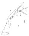
- FIG. 1illustrates a perspective view of a system including a firearm coupled with a stabilization device in a stored state, in accordance with an embodiment of the present invention
- FIG. 2illustrates a perspective view of the system with the stabilization device in a deployed state, in accordance with an embodiment of the present invention
- FIG. 3illustrates a partially exploded perspective view of the stabilization device, in accordance with an embodiment of the present invention
- FIG. 4illustrates an assembled perspective view of the stabilization device, in accordance with an embodiment of the present invention
- FIG. 5illustrates a cross-sectional view of a head unit coupled to the mount in the stored state, in accordance with an embodiment of the present invention
- FIG. 6illustrates a cross-sectional view of the head unit coupled to the mount in the deployed state, in accordance with an embodiment of the present invention
- FIG. 7illustrates a front view of various components of the stabilization device with the legs being in a stored position, in accordance with an embodiment of the present invention.
- FIG. 8illustrates a front view of the various components of the stabilization device with the legs being in the deployed position, in accordance with an embodiment of the present invention.
- Various embodiments of the inventionmay provide for a stabilization device capable of quick and dependable deployment for the stabilization of a firearm coupled thereto.
- FIG. 1depicts a perspective view of a system 100 including a stabilization device 104 coupled to a firearm 108 to facilitate the stabilized discharge of the firearm 108 in accordance with an embodiment of the present invention.
- the stabilization device 104may have two legs 112 and may, in this instance, be referred to as a bipod. In other embodiments, the stabilization device 104 may have one leg, i.e., monopod, or more than two legs, e.g., tripod or polypod.
- the stabilization device 104may include a mount 116 to couple to a fore-end 120 of a stock of the firearm 108 , as shown in FIG. 1 .
- the mount 116may have a surface that is contoured in a manner to complement the coupling surface of the firearm 108 , e.g., the portion of the fore-end 120 that the mount 116 is coupled to.
- the mount 116may be coupled to the barrel 124 of the firearm 108 .
- the mount 116may be coupled to the fore-end 120 by a bolt that may also serve as an attachment point for a sling.
- FIG. 1illustrates the stabilization device 104 being in a stored state.
- the stabilization device 104may be disposed in a manner that positions the legs 112 substantially parallel to one another and to the mounting surface of the mount 116 . With the stabilization device 104 so disposed, the legs 112 may be adjacent to the barrel 124 , as shown in FIG. 1 .
- This designmay allow for the stabilization device 104 to be substantially within the outer profile dimensions of the firearm 108 , e.g., defined by a line from the butt of the grip to the end of the barrel, while in the stored state. This may in turn facilitate the portability of the system 100 in accordance with an embodiment of the present invention.
- the stabilization device 104may have a deployment mechanism that allows the stabilization device 104 to transition between the stored state, illustrated in FIG. 1 , and the deployed state, illustrated in FIG. 2 , in accordance with an embodiment of the present invention.
- the deployment mechanismwhich will be described later in further detail, may be easily accomplished with one hand, allowing the operator to hold the firearm 108 with the other.
- the deployed state of the stabilization device 104 illustrated in FIG. 2may orient a head unit 200 substantially orthogonal to the mounting surface of the mount 116 . Additionally, the illustrated deployed state shows that the legs 112 may be in a splayed position while in the deployed state. This splayed position of the legs 112 may allow them to contact a supporting surface in a manner to steadily transfer at least a portion of the weight of the firearm 108 to the supporting surface.
- the support provided by the stabilization device 104may be used to facilitate the aiming and subsequent discharge of the firearm 108 .
- the legs 112may have adjustable lengths to accommodate the orientation of the operator, e.g., prone, kneel, or upright, as well as the topography of the terrain that is used as a supporting surface.
- the legs 112may be adjustable through, e.g., a telescoping manner.
- the legs 112may each have an upper leg 204 disposed within a lower leg 208 .
- the upper and lower legsmay be secured relative to one another at a desired height.
- the upper and lower legsmay be secured to each other by latches 212 .
- the legs 112may have adjustable heights through other telescoping and non-telescoping manners.
- the firearm 108may be any type of device adapted to propel a projectile with a high velocity.
- the propulsion forcemay be provided by deflagration caused by an incendiary such as, e.g., gunpowder.
- the firearm 108is not so limited in other embodiments.
- the propulsion forcemay be applied to the projectile through gas pressure. Therefore, in various embodiments the firearm 108 may be, but is not limited to, a rifle, a gun, a pistol, or an air gun.
- the system 100may be used in a number of applications including, but not limited to, police and military uses, hunting, or gaming (e.g., paintball).
- FIGS. 3-4respectively illustrate partially-exploded and assembled perspective views of the stabilization device 104 , in accordance with an embodiment of the present invention.
- the mount 116may include a mount base 300 that is coupled to a mount cap 304 with a ball 308 disposed in between.
- the mount base 300may be coupled to the mount cap 304 by screws, bolts, snaps, or some other securing mechanism.
- the ball 308may be hollow so that a head pin 312 may be disposed through the ball 308 and a spring 316 , wrapped around the head pin 312 , may be disposed inside of the ball 308 .
- the mount 116may be coupled to the head unit 200 by the head pin 312 .
- the head pin 312may have male threads on a first end that screw directly into a female threaded hole in the head unit 200 .
- the head pin 312may be inserted into a hole of the head unit 200 and secured by a cross pin.
- the cap 304may have a cutout 324 adapted to provide the head pin 312 a path for transitioning the head unit 200 between the stored and deployed states.
- the cutout 324may also include a cross path that may allow for the mount 116 , and firearm 108 , to tilt a certain amount back and forth while the head unit 200 is in the deployed state. This tilt range may be up to, e.g., ⁇ 25 degrees.
- leg tops 328may be pivotally coupled to the head unit 200 .
- the head unit 200may have a recess 332 designed to allow the leg tops 328 to rotate between parallel and splayed positions.
- the leg tops 328may be pivotally coupled to the head unit 200 by a connecting link 336 that also couples a cam plate 340 to the head unit 200 .
- the connecting link 336may be disposed through the head unit 200 and secured with a retainer (not shown) on the opposite side of the head unit 200 .
- the cam plate 340may be coupled to the head unit 200 in a manner that allows linear motion between the two components, to be discussed in further detail later.
- One or more cam guide pins 344may be coupled to the head unit 200 and engage tracks of the cam plate 340 to facilitate this linear motion.
- the leg tops 328may also have guide pins 348 to engage tracks of the cam plate 340 .
- leg tops 328may be compression fit into cavities of the legs 112 .
- Other embodimentsmay employ other coupling mechanisms such as, but not limited to, screw tops.
- the legs tops 328may be part of the legs 112 themselves.
- the distal end of the legs 112may be fit with leg tips 352 .
- the tips 352may be a rubber material that is designed to provide traction with the supporting surface.
- the legs 112may be fit with plugs.
- FIG. 5illustrates a cross-sectional view of the head unit 200 coupled to the mount 116 in the stored position in accordance with an embodiment of the present invention.
- the head pin 312is coupled to the head unit 200 by a cross pin 500 that may also serve as a guide pin 344 .
- the head pin 312may be disposed through the ball 308 .
- the spring 316may be wrapped around the head pin 312 and may exert a spring force against the interior of ball 308 and the head pin 312 .
- the head pin 312may include a collar 502 to control the amount the end 504 that is exposed beyond the ball 308 and to provide a surface for the spring 316 to press against. The spring force may cause the head pin 312 to engage the mount 116 .
- the head pin 312may engage the mount 116 by having a first end 504 at least partially disposed within a recess 508 .
- the recess 508 of this embodimentmay be formed by complementary cutouts of the base 300 and the cap 304 .
- the recess 508may be an indention in the interior wall of the mount 116 , or alternatively, may be a through-hole.
- the head pin 312may be disengaged from the mount 116 by exerting a transitional force on the head pin 312 in a direction away from the mount 116 to overcome the spring force of the spring 316 .
- This transitional forcemay be exerted by an operator pulling on the head unit 200 .
- the head unit 200With the end 504 retracted from the recess 508 the head unit 200 may transition from the stored state shown in FIG. 5 to the deployed state shown in FIG. 6 , in accordance with an embodiment of the present invention. In transition between the two states, the portion of the head pin 312 that is between the ball 308 and the head unit 200 may travel along the cutout 324 of the cap 304 .
- the spring forcemay cause the head pin 312 to reengage the mount 116 by having the end 504 become at least partially disposed within a recess 604 .
- the recess 604may have a complementary path to allow the end 504 to travel back and forth without the head pin 312 disengaging the mount 116 .
- the recess 604may be an indention in the interior wall of the mount 116 (and more particularly the base 300 ), it may be a through-hole, or some combination of the two.
- FIG. 7illustrates a front view of various components of the stabilization device 104 with the legs 112 being in a stored position, in accordance with an embodiment of the present invention.
- the cam plate 340may have tracks 704 .
- the tracks 704may each have two portions, e.g., a link-pin portion 704 a for the pins of the connecting link 336 , and a leg-pin portion 704 b for the leg-top pins 348 . While the legs 112 are in the stored position the leg-top pins 348 may be at the interface of the link-pin portion 704 a and the leg-pin portion 704 b.
- the cam plate 340may also have two guide pin tracks 708 in which the guide pins 344 are disposed.
- the guide pins 344 , guide pin tracks 708 , connecting link 336 , and tracks 704may all cooperate to provide a delineated path for relative linear motion between the cam plate 340 and the head unit 200 .
- the two tracks 704may be substantially symmetrical to one another.
- the leg-pin portions 704 b and the leg-top pins 348may cooperate in a manner to provide even deployment of the leg tops 328 from the substantially parallel position shown in FIG. 7 to the splayed position shown in FIG. 8 .
- the cam plate 340will travel upward relative to the head unit 200 causing the other leg 112 to rotate outward in a similar manner as the leg-top pins 348 travel through the leg-pin portions 704 b of the tracks 704 .
- the steady and even deployment of the legs 112may result without the need for any springs. This may facilitate repetitive and reliable deployment of the legs 112 without relying on exposed springs.
Landscapes
- Engineering & Computer Science (AREA)
- General Engineering & Computer Science (AREA)
- Aiming, Guidance, Guns With A Light Source, Armor, Camouflage, And Targets (AREA)
Abstract
Description
Claims (9)
Priority Applications (1)
| Application Number | Priority Date | Filing Date | Title |
|---|---|---|---|
| US11/317,657US7426800B2 (en) | 2004-12-22 | 2005-12-22 | Stabilization device |
Applications Claiming Priority (2)
| Application Number | Priority Date | Filing Date | Title |
|---|---|---|---|
| US63864704P | 2004-12-22 | 2004-12-22 | |
| US11/317,657US7426800B2 (en) | 2004-12-22 | 2005-12-22 | Stabilization device |
Publications (2)
| Publication Number | Publication Date |
|---|---|
| US20060248774A1 US20060248774A1 (en) | 2006-11-09 |
| US7426800B2true US7426800B2 (en) | 2008-09-23 |
Family
ID=37392800
Family Applications (1)
| Application Number | Title | Priority Date | Filing Date |
|---|---|---|---|
| US11/317,657Expired - Fee RelatedUS7426800B2 (en) | 2004-12-22 | 2005-12-22 | Stabilization device |
Country Status (1)
| Country | Link |
|---|---|
| US (1) | US7426800B2 (en) |
Cited By (49)
| Publication number | Priority date | Publication date | Assignee | Title |
|---|---|---|---|---|
| US20080023915A1 (en)* | 2006-02-24 | 2008-01-31 | Battenfeld Technologies, Inc. | Shooting gallery devices and methods |
| US20080174071A1 (en)* | 2006-02-24 | 2008-07-24 | Battenfeld Technologies, Inc. | Shooting gallery devices and methods |
| US20080263928A1 (en)* | 2007-02-26 | 2008-10-30 | Battenfeld Technologies, Inc. | Firearm supports and gas-assisted methods of filling firearm supports |
| US20090000175A1 (en)* | 2007-05-08 | 2009-01-01 | Battenfeld Technologies, Inc. | Adjustable firearm supports and associated methods of use and manufacture |
| US20090140119A1 (en)* | 2007-11-30 | 2009-06-04 | Chun Yuen To | Support stand for notebook |
| US7676977B1 (en)* | 2005-12-04 | 2010-03-16 | Tango Down, Inc. | Bipod |
| US7690606B1 (en)* | 2007-03-26 | 2010-04-06 | Wes Batdorf | Universal work stand |
| US7726478B2 (en) | 2006-02-27 | 2010-06-01 | Battenfeld Technologies, Inc. | Containers for carrying firearm accessories and/or supporting firearms |
| US7774972B2 (en) | 2006-09-11 | 2010-08-17 | Battenfeld Technologies, Inc. | Modular shooting rests and shooting rest assemblies |
| US7779572B2 (en) | 2006-05-08 | 2010-08-24 | Battenfeld Technologies, Inc. | Bipod device for use with a firearm |
| US20100270201A1 (en)* | 2006-02-27 | 2010-10-28 | Battenfeld Technologies, Inc. | Portable storage case with integral stabilizing platform for use with a firearm support |
| US7823317B2 (en) | 2006-08-22 | 2010-11-02 | Battenfeld Technologies, Inc. | Adjustable shooting rests and shooting rest assemblies |
| US7845267B2 (en) | 2007-09-11 | 2010-12-07 | Battenfield Technologies, Inc. | Attachment mechanisms for coupling firearms to supporting structures |
| US7946070B1 (en)* | 2006-09-12 | 2011-05-24 | Tom Elhart | Shooting stick apparatus |
| US20110167705A1 (en)* | 2008-11-21 | 2011-07-14 | Battenfeld Technologies, Inc. | Shooting rests with adjustable height assemblies |
| US8011129B2 (en) | 2003-06-13 | 2011-09-06 | Battenfeld Technologies, Inc. | Recoil-reducing shooting rest |
| US8104212B2 (en) | 2006-02-24 | 2012-01-31 | Battenfeld Technologies, Inc. | Firearm supports, such as shooting bags, and firearm support assemblies |
| US20120258842A1 (en)* | 2011-04-08 | 2012-10-11 | Share Solutions, Llc | Health aid and method for treating pain |
| US8291633B1 (en)* | 2008-10-22 | 2012-10-23 | Fn Manufacturing, Llc | Bipod for light-weight machine gun |
| US8296988B2 (en) | 2006-11-30 | 2012-10-30 | Battenfeld Technologies, Inc. | Firearm supporting devices, methods of assembling firearm supporting devices, and methods of packaging firearm supporting devices |
| US8336708B2 (en) | 2007-07-20 | 2012-12-25 | Battenfeld Technologies, Inc. | System and container for organizing and carrying tools and tool sets |
| US8371057B2 (en) | 2006-05-09 | 2013-02-12 | Battenfeld Technologies, Inc. | Firearm cleaning apparatus with protective coating |
| US20130036647A1 (en)* | 2011-08-12 | 2013-02-14 | Advanced Technology International USA, LLC | Retractable bipod assembly for firearm |
| US20130256475A1 (en)* | 2012-01-17 | 2013-10-03 | Field Optics Research | Article Supports and Adapters Therefor |
| US8578645B2 (en) | 2004-11-10 | 2013-11-12 | Battenfeld Technologies, Inc. | Firearm vise |
| US8596597B1 (en)* | 2011-01-04 | 2013-12-03 | Simone Spicer | Paint roller support device |
| US8621773B2 (en) | 2003-06-13 | 2014-01-07 | Battenfeld Technologies, Inc. | Shooting rests for supporting firearms |
| US8695985B2 (en) | 2011-01-07 | 2014-04-15 | Battenfeld Technologies, Inc. | Stowable shooting target assemblies |
| US8931201B2 (en) | 2012-12-31 | 2015-01-13 | Battenfeld Technologies, Inc. | Gun support apparatus |
| US20150023656A1 (en)* | 2003-12-02 | 2015-01-22 | Grip Pod Systems International, Llc | Vertical Fore Grip with Bipod |
| US20150121741A1 (en)* | 2013-11-01 | 2015-05-07 | Lorne Bowman | Adjustable Firearm Support |
| US20160054089A1 (en)* | 2013-01-04 | 2016-02-25 | Gerry Paul Sherman | Rifle support |
| US9463352B2 (en) | 2011-04-08 | 2016-10-11 | Share Solutions, Llc | Health aid kit and method for treating pain |
| US9702653B2 (en) | 2015-10-09 | 2017-07-11 | Battenfeld Technologies, Inc. | Firearm shooting rest |
| US9803950B1 (en)* | 2016-08-05 | 2017-10-31 | Axion Archery Llc | Archery bow stand |
| US9903528B1 (en)* | 2014-09-22 | 2018-02-27 | Joshua Terry Hatch | Telescoping lock mechanism |
| US10161706B2 (en)* | 2016-12-23 | 2018-12-25 | Magpul Industries Corp. | Firearm bipod |
| US10168119B2 (en)* | 2016-12-23 | 2019-01-01 | Magpul Industries Corp. | Firearm bipod |
| US20190025009A1 (en)* | 2017-07-19 | 2019-01-24 | Bow Rigger LLC | Bow Stand With Fully Adjustable Stabilizing Capability |
| US10408555B2 (en)* | 2017-01-14 | 2019-09-10 | WSM Manufacturing, LLC | Bipod |
| US10514225B2 (en) | 2018-01-17 | 2019-12-24 | Battenfeld Technologies, Inc. | Firearm shooting rest |
| US10591240B2 (en) | 2016-03-04 | 2020-03-17 | Blk Lbl Corporation | Retractable firearm support assembly |
| US10782085B2 (en) | 2019-02-15 | 2020-09-22 | Aob Products Company | Recoil-reducing firearm shooting rest having tank |
| US11391533B2 (en)* | 2018-01-08 | 2022-07-19 | McEwin Design Pty Ltd | Rifle bipod |
| US11841108B2 (en) | 2019-12-17 | 2023-12-12 | Aob Products Company | Multi-legged equipment support having leg angle adjustment |
| US11874080B1 (en)* | 2022-12-30 | 2024-01-16 | Xiaohui Ye | Universal supporting mechanism |
| USD1012219S1 (en) | 2020-01-20 | 2024-01-23 | Sagi Faifer | Bipod for a gun |
| US12004658B2 (en) | 2021-04-15 | 2024-06-11 | Aob Products Company | Shooting rest chair |
| USD1068591S1 (en) | 2022-02-07 | 2025-04-01 | Sagi Faifer | Accessory assembly for a bicycle handlebar |
Families Citing this family (7)
| Publication number | Priority date | Publication date | Assignee | Title |
|---|---|---|---|---|
| US7631455B2 (en)* | 2004-02-12 | 2009-12-15 | Da Keng | Quick disconnect bipod mount assembly with adjustable and lockable tilt, pan and cant controls |
| US20080023379A1 (en)* | 2006-04-26 | 2008-01-31 | Battenfeld Technologies, Inc. | Media separation systems and methods |
| US20090038200A1 (en)* | 2007-03-06 | 2009-02-12 | Da Keng | Bipod Mount with Integral Hand Grip |
| US7841122B1 (en)* | 2007-07-20 | 2010-11-30 | Phoenix Tactical, LLC | Adaptable leg support for bipod assemblies |
| CA2913245C (en) | 2013-05-24 | 2019-02-19 | Brent J. Ravnaas | Firearm stock with support |
| US9709356B1 (en)* | 2014-05-06 | 2017-07-18 | Tja Design Llc | Multi-axis firearm foregrip |
| CN109819669B (en)* | 2016-09-01 | 2022-03-11 | 精度解决方案有限责任公司 | Extensions for gun supports |
Citations (9)
| Publication number | Priority date | Publication date | Assignee | Title |
|---|---|---|---|---|
| US2472804A (en)* | 1947-08-29 | 1949-06-14 | John R Bird | Combination mount and shoulder rest |
| EP0127193A1 (en)* | 1980-12-11 | 1984-12-05 | Chartered Industries Of Singapore Private Limited | Bipod for a gun and a gun embodying same |
| US5074188A (en) | 1990-12-19 | 1991-12-24 | Gerald Harris | Pivotal bipod adapter |
| US5390885A (en) | 1994-03-21 | 1995-02-21 | Shen; Jack | Locking mechanism for a portable tripod of a Q-pad |
| US5749549A (en)* | 1995-12-29 | 1998-05-12 | Javad Positioning, Llc | Satellite positioning system antenna supporting tripod |
| US5815974A (en) | 1995-10-13 | 1998-10-06 | Keng; Da | Bipod mounting device |
| US6487807B1 (en) | 2001-03-16 | 2002-12-03 | Matt Kopman | Tripod gun handle |
| US6663071B2 (en) | 2001-08-28 | 2003-12-16 | Thomas K. M. Peterson | Telescoping multipod support apparatus |
| US6763627B1 (en) | 2003-07-16 | 2004-07-20 | Fn Mfg Inc | Bipod for light-weight machine gun |
- 2005
- 2005-12-22USUS11/317,657patent/US7426800B2/ennot_activeExpired - Fee Related
Patent Citations (9)
| Publication number | Priority date | Publication date | Assignee | Title |
|---|---|---|---|---|
| US2472804A (en)* | 1947-08-29 | 1949-06-14 | John R Bird | Combination mount and shoulder rest |
| EP0127193A1 (en)* | 1980-12-11 | 1984-12-05 | Chartered Industries Of Singapore Private Limited | Bipod for a gun and a gun embodying same |
| US5074188A (en) | 1990-12-19 | 1991-12-24 | Gerald Harris | Pivotal bipod adapter |
| US5390885A (en) | 1994-03-21 | 1995-02-21 | Shen; Jack | Locking mechanism for a portable tripod of a Q-pad |
| US5815974A (en) | 1995-10-13 | 1998-10-06 | Keng; Da | Bipod mounting device |
| US5749549A (en)* | 1995-12-29 | 1998-05-12 | Javad Positioning, Llc | Satellite positioning system antenna supporting tripod |
| US6487807B1 (en) | 2001-03-16 | 2002-12-03 | Matt Kopman | Tripod gun handle |
| US6663071B2 (en) | 2001-08-28 | 2003-12-16 | Thomas K. M. Peterson | Telescoping multipod support apparatus |
| US6763627B1 (en) | 2003-07-16 | 2004-07-20 | Fn Mfg Inc | Bipod for light-weight machine gun |
Cited By (85)
| Publication number | Priority date | Publication date | Assignee | Title |
|---|---|---|---|---|
| US9151561B2 (en) | 2003-06-13 | 2015-10-06 | Battenfeld Technologies, Inc. | Shooting rests for supporting firearms |
| US10859336B2 (en) | 2003-06-13 | 2020-12-08 | Aob Products Company | Shooting rests for supporting firearms |
| US10317162B2 (en) | 2003-06-13 | 2019-06-11 | Battenfeld Technologies, Inc. | Shooting rests for supporting firearms |
| US8011129B2 (en) | 2003-06-13 | 2011-09-06 | Battenfeld Technologies, Inc. | Recoil-reducing shooting rest |
| US8621773B2 (en) | 2003-06-13 | 2014-01-07 | Battenfeld Technologies, Inc. | Shooting rests for supporting firearms |
| US9285075B2 (en)* | 2003-12-02 | 2016-03-15 | Grip Pod Systems International, Llc | Vertical fore grip with bipod |
| US10502365B2 (en) | 2003-12-02 | 2019-12-10 | Grip Pod Systems International, Llc | Vertical fore grip with bipod |
| US20150023656A1 (en)* | 2003-12-02 | 2015-01-22 | Grip Pod Systems International, Llc | Vertical Fore Grip with Bipod |
| US10113692B2 (en) | 2003-12-02 | 2018-10-30 | Grip Pod Systems International, Llc | Vertical fore grip with bipod |
| US9611977B2 (en) | 2003-12-02 | 2017-04-04 | Grip Pod Systems International, Llc | Vertical fore grip with bipod |
| US8578645B2 (en) | 2004-11-10 | 2013-11-12 | Battenfeld Technologies, Inc. | Firearm vise |
| US7676977B1 (en)* | 2005-12-04 | 2010-03-16 | Tango Down, Inc. | Bipod |
| US7681886B2 (en) | 2006-02-24 | 2010-03-23 | Battenfeld Technologies, Inc. | Shooting gallery devices and methods |
| US20080023915A1 (en)* | 2006-02-24 | 2008-01-31 | Battenfeld Technologies, Inc. | Shooting gallery devices and methods |
| US20080174071A1 (en)* | 2006-02-24 | 2008-07-24 | Battenfeld Technologies, Inc. | Shooting gallery devices and methods |
| US8104212B2 (en) | 2006-02-24 | 2012-01-31 | Battenfeld Technologies, Inc. | Firearm supports, such as shooting bags, and firearm support assemblies |
| US20100270201A1 (en)* | 2006-02-27 | 2010-10-28 | Battenfeld Technologies, Inc. | Portable storage case with integral stabilizing platform for use with a firearm support |
| US7726478B2 (en) | 2006-02-27 | 2010-06-01 | Battenfeld Technologies, Inc. | Containers for carrying firearm accessories and/or supporting firearms |
| US7779572B2 (en) | 2006-05-08 | 2010-08-24 | Battenfeld Technologies, Inc. | Bipod device for use with a firearm |
| US8316570B2 (en) | 2006-05-08 | 2012-11-27 | Battenfeld Technologies, Inc. | Bipod device for use with a firearm |
| US8371057B2 (en) | 2006-05-09 | 2013-02-12 | Battenfeld Technologies, Inc. | Firearm cleaning apparatus with protective coating |
| US8132351B2 (en) | 2006-08-22 | 2012-03-13 | Battenfeld Technologies, Inc. | Adjustable shooting rests and shooting rest assemblies |
| US7823317B2 (en) | 2006-08-22 | 2010-11-02 | Battenfeld Technologies, Inc. | Adjustable shooting rests and shooting rest assemblies |
| US8356442B2 (en) | 2006-08-22 | 2013-01-22 | Battenfeld Technologies, Inc. | Adjustable shooting rests and shooting rest assemblies |
| US7774972B2 (en) | 2006-09-11 | 2010-08-17 | Battenfeld Technologies, Inc. | Modular shooting rests and shooting rest assemblies |
| US7946070B1 (en)* | 2006-09-12 | 2011-05-24 | Tom Elhart | Shooting stick apparatus |
| US8296988B2 (en) | 2006-11-30 | 2012-10-30 | Battenfeld Technologies, Inc. | Firearm supporting devices, methods of assembling firearm supporting devices, and methods of packaging firearm supporting devices |
| US20080263928A1 (en)* | 2007-02-26 | 2008-10-30 | Battenfeld Technologies, Inc. | Firearm supports and gas-assisted methods of filling firearm supports |
| US7690606B1 (en)* | 2007-03-26 | 2010-04-06 | Wes Batdorf | Universal work stand |
| US8327570B2 (en)* | 2007-05-08 | 2012-12-11 | Battenfeld Technologies, Inc. | Adjustable firearm supports and associated methods of use and manufacture |
| US20090000175A1 (en)* | 2007-05-08 | 2009-01-01 | Battenfeld Technologies, Inc. | Adjustable firearm supports and associated methods of use and manufacture |
| US7954272B2 (en)* | 2007-05-08 | 2011-06-07 | Battenfeld Technologies, Inc. | Adjustable firearm supports and associated methods of use and manufacture |
| US20120085012A1 (en)* | 2007-05-08 | 2012-04-12 | Battenfeld Technologies, Inc. | Adjustable firearm supports and associated methods of use and manufacture |
| US8336708B2 (en) | 2007-07-20 | 2012-12-25 | Battenfeld Technologies, Inc. | System and container for organizing and carrying tools and tool sets |
| US7845267B2 (en) | 2007-09-11 | 2010-12-07 | Battenfield Technologies, Inc. | Attachment mechanisms for coupling firearms to supporting structures |
| US8464628B2 (en) | 2007-09-11 | 2013-06-18 | Battenfeld Technologies, Inc. | Attachment mechanisms for coupling firearms to supporting structures |
| US20090140119A1 (en)* | 2007-11-30 | 2009-06-04 | Chun Yuen To | Support stand for notebook |
| US8291633B1 (en)* | 2008-10-22 | 2012-10-23 | Fn Manufacturing, Llc | Bipod for light-weight machine gun |
| US20110167705A1 (en)* | 2008-11-21 | 2011-07-14 | Battenfeld Technologies, Inc. | Shooting rests with adjustable height assemblies |
| US7997021B2 (en) | 2008-11-21 | 2011-08-16 | Battenfeld Technologies | Shooting rests with adjustable height assemblies |
| US8393106B2 (en) | 2008-11-21 | 2013-03-12 | Battenfeld Technologies, Inc. | Shooting rests with adjustable height for supporting firearms |
| US8596597B1 (en)* | 2011-01-04 | 2013-12-03 | Simone Spicer | Paint roller support device |
| US8695985B2 (en) | 2011-01-07 | 2014-04-15 | Battenfeld Technologies, Inc. | Stowable shooting target assemblies |
| US8961374B2 (en)* | 2011-04-08 | 2015-02-24 | Share Solutions, Llc | Health aid and method for treating pain |
| US9463352B2 (en) | 2011-04-08 | 2016-10-11 | Share Solutions, Llc | Health aid kit and method for treating pain |
| US20120258842A1 (en)* | 2011-04-08 | 2012-10-11 | Share Solutions, Llc | Health aid and method for treating pain |
| US20130036647A1 (en)* | 2011-08-12 | 2013-02-14 | Advanced Technology International USA, LLC | Retractable bipod assembly for firearm |
| US8567106B2 (en)* | 2011-08-12 | 2013-10-29 | Advanced Technology International USA, LLC | Retractable bipod assembly for firearm |
| US20130256475A1 (en)* | 2012-01-17 | 2013-10-03 | Field Optics Research | Article Supports and Adapters Therefor |
| US8931201B2 (en) | 2012-12-31 | 2015-01-13 | Battenfeld Technologies, Inc. | Gun support apparatus |
| US20160054089A1 (en)* | 2013-01-04 | 2016-02-25 | Gerry Paul Sherman | Rifle support |
| US10739099B2 (en)* | 2013-11-01 | 2020-08-11 | Lorne Bowman | Adjustable firearm support |
| US20150121741A1 (en)* | 2013-11-01 | 2015-05-07 | Lorne Bowman | Adjustable Firearm Support |
| US10386011B2 (en)* | 2014-09-22 | 2019-08-20 | Joshua Terry Hatch | Telescoping lock mechanism |
| US9903528B1 (en)* | 2014-09-22 | 2018-02-27 | Joshua Terry Hatch | Telescoping lock mechanism |
| US11313509B2 (en) | 2014-09-22 | 2022-04-26 | Joshua Terry Hatch | Telescoping lock mechanism |
| US9702653B2 (en) | 2015-10-09 | 2017-07-11 | Battenfeld Technologies, Inc. | Firearm shooting rest |
| US10591240B2 (en) | 2016-03-04 | 2020-03-17 | Blk Lbl Corporation | Retractable firearm support assembly |
| US10900736B2 (en) | 2016-03-04 | 2021-01-26 | Blk Lbl Corporation | Retractable firearm support assembly |
| US9803950B1 (en)* | 2016-08-05 | 2017-10-31 | Axion Archery Llc | Archery bow stand |
| US12422209B2 (en) | 2016-12-23 | 2025-09-23 | Magpul Industries Corp. | Firearm bipod |
| US10627181B2 (en) | 2016-12-23 | 2020-04-21 | Magpul Industries Corp. | Firearm bipod |
| US10739100B2 (en) | 2016-12-23 | 2020-08-11 | Magpul Industries Corp. | Firearm bipod |
| US11732991B2 (en) | 2016-12-23 | 2023-08-22 | Magpul Industries Corp. | Firearm bipod |
| US10168119B2 (en)* | 2016-12-23 | 2019-01-01 | Magpul Industries Corp. | Firearm bipod |
| US11867473B2 (en) | 2016-12-23 | 2024-01-09 | Magpul Industries Corp. | Firearm bipod |
| US10161706B2 (en)* | 2016-12-23 | 2018-12-25 | Magpul Industries Corp. | Firearm bipod |
| US10794655B2 (en) | 2017-01-14 | 2020-10-06 | WSM Manufacturing, LLC | Bipod |
| US10408555B2 (en)* | 2017-01-14 | 2019-09-10 | WSM Manufacturing, LLC | Bipod |
| US11085730B2 (en)* | 2017-07-19 | 2021-08-10 | Bow Rigger LLC | Bow stand with fully adjustable stabilizing capability |
| US20190025009A1 (en)* | 2017-07-19 | 2019-01-24 | Bow Rigger LLC | Bow Stand With Fully Adjustable Stabilizing Capability |
| US11391533B2 (en)* | 2018-01-08 | 2022-07-19 | McEwin Design Pty Ltd | Rifle bipod |
| US11009306B2 (en) | 2018-01-17 | 2021-05-18 | Aob Products Company | Firearm shooting rest |
| US10514225B2 (en) | 2018-01-17 | 2019-12-24 | Battenfeld Technologies, Inc. | Firearm shooting rest |
| US10782085B2 (en) | 2019-02-15 | 2020-09-22 | Aob Products Company | Recoil-reducing firearm shooting rest having tank |
| US11796274B2 (en) | 2019-02-15 | 2023-10-24 | Aob Products Company | Recoil-reducing firearm shooting rest having tank |
| US12228361B2 (en) | 2019-02-15 | 2025-02-18 | Aob Products Company | Recoil-reducing firearm shooting rest having tank |
| US11333461B2 (en) | 2019-02-15 | 2022-05-17 | Aob Products Company | Recoil-reducing firearm shooting rest having tank |
| US11841108B2 (en) | 2019-12-17 | 2023-12-12 | Aob Products Company | Multi-legged equipment support having leg angle adjustment |
| US12146608B2 (en) | 2019-12-17 | 2024-11-19 | Aob Products Company | Multi-legged equipment support having leg angle adjustment |
| USD1012219S1 (en) | 2020-01-20 | 2024-01-23 | Sagi Faifer | Bipod for a gun |
| US12004658B2 (en) | 2021-04-15 | 2024-06-11 | Aob Products Company | Shooting rest chair |
| US12408757B2 (en) | 2021-04-15 | 2025-09-09 | Aob Products Company | Shooting rest chair |
| USD1068591S1 (en) | 2022-02-07 | 2025-04-01 | Sagi Faifer | Accessory assembly for a bicycle handlebar |
| US11874080B1 (en)* | 2022-12-30 | 2024-01-16 | Xiaohui Ye | Universal supporting mechanism |
Also Published As
| Publication number | Publication date |
|---|---|
| US20060248774A1 (en) | 2006-11-09 |
Similar Documents
| Publication | Publication Date | Title |
|---|---|---|
| US7426800B2 (en) | Stabilization device | |
| US7401431B2 (en) | Trigger actuated stabilization device | |
| US4026054A (en) | Laser aiming system for weapons | |
| US7891126B2 (en) | Canting vertical fore grip with bipod | |
| US8225543B2 (en) | Canting vertical fore grip with bipod | |
| US7434773B1 (en) | Adjustable support for archery bows and the like | |
| US6779290B1 (en) | Semi permanent backup iron sight | |
| US6272785B1 (en) | Gun holder | |
| US8316570B2 (en) | Bipod device for use with a firearm | |
| US10900736B2 (en) | Retractable firearm support assembly | |
| US7143986B1 (en) | Stabilizing device | |
| US9121665B2 (en) | Gun with internally stored bipod and monopod | |
| US8448369B2 (en) | Bipod device for use with Picatinny rail | |
| US9151562B1 (en) | Locking adjustable rifle stand | |
| US10012465B1 (en) | Modular device support system | |
| US12209830B2 (en) | Recoil management system | |
| US7669357B2 (en) | Rotating and canting vertical fore grip with bipod | |
| US20140237882A1 (en) | Stabilization Shooting Platform | |
| US10161707B2 (en) | Shooting-stability platform for firearms | |
| EP3507563B1 (en) | An extension for a gun support | |
| US20210318096A1 (en) | Handgun supporting facility | |
| US7047960B2 (en) | Bow stabilization device | |
| US7124528B2 (en) | Firearm pistol grip monopod gun stabilizer | |
| EP1026471A2 (en) | Support mechanism for firearms | |
| EP3557178B1 (en) | An extension for a bipod support included in the stock of the gun |
Legal Events
| Date | Code | Title | Description |
|---|---|---|---|
| AS | Assignment | Owner name:BUSHNELL OUTDOOR PRODUCTS, KANSAS Free format text:ASSIGNMENT OF ASSIGNORS INTEREST;ASSIGNORS:FOX, MICHAEL R.;PIERCE, ROD;HOFFMAN, TODD;AND OTHERS;REEL/FRAME:022203/0759 Effective date:20071101 | |
| AS | Assignment | Owner name:BUSHNELL INC., KANSAS Free format text:ASSIGNMENT OF ASSIGNORS INTEREST;ASSIGNORS:MAGNUM VENTURES, LLC;OUTBACK CONCEPTS, LLC;PIERCE, ROD;AND OTHERS;REEL/FRAME:025105/0823 Effective date:20101006 | |
| FPAY | Fee payment | Year of fee payment:4 | |
| AS | Assignment | Owner name:BANK OF AMERICA, N.A., CALIFORNIA Free format text:SECURITY AGREEMENT;ASSIGNORS:BEE STINGER, LLC;BOLLE AMERICA, INC.;BOLLE, INC.;AND OTHERS;REEL/FRAME:031765/0300 Effective date:20131101 | |
| AS | Assignment | Owner name:BOLLE, INC., KANSAS Free format text:INTELLECTUAL PROPERTY SECURITY AGREEMENT RELEASE;ASSIGNOR:BANK OF AMERICA, N.A.;REEL/FRAME:034982/0178 Effective date:20150209 Owner name:DOUBLE BULL ARCHERY, INC., MISSISSIPPI Free format text:INTELLECTUAL PROPERTY SECURITY AGREEMENT RELEASE;ASSIGNOR:BANK OF AMERICA, N.A.;REEL/FRAME:034982/0178 Effective date:20150209 Owner name:PRIMOS, INC., MISSISSIPPI Free format text:INTELLECTUAL PROPERTY SECURITY AGREEMENT RELEASE;ASSIGNOR:BANK OF AMERICA, N.A.;REEL/FRAME:034982/0178 Effective date:20150209 Owner name:OLD WSR, INC., KANSAS Free format text:INTELLECTUAL PROPERTY SECURITY AGREEMENT RELEASE;ASSIGNOR:BANK OF AMERICA, N.A.;REEL/FRAME:034982/0178 Effective date:20150209 Owner name:BUSHNELL GROUP HOLDINGS, INC., KANSAS Free format text:INTELLECTUAL PROPERTY SECURITY AGREEMENT RELEASE;ASSIGNOR:BANK OF AMERICA, N.A.;REEL/FRAME:034982/0178 Effective date:20150209 Owner name:SERENGETI EYEWEAR, INC., KANSAS Free format text:INTELLECTUAL PROPERTY SECURITY AGREEMENT RELEASE;ASSIGNOR:BANK OF AMERICA, N.A.;REEL/FRAME:034982/0178 Effective date:20150209 Owner name:BOLLE AMERICA, INC., KANSAS Free format text:INTELLECTUAL PROPERTY SECURITY AGREEMENT RELEASE;ASSIGNOR:BANK OF AMERICA, N.A.;REEL/FRAME:034982/0178 Effective date:20150209 Owner name:MICHAELS OF OREGON CO., KANSAS Free format text:INTELLECTUAL PROPERTY SECURITY AGREEMENT RELEASE;ASSIGNOR:BANK OF AMERICA, N.A.;REEL/FRAME:034982/0178 Effective date:20150209 Owner name:MILLETT INDUSTRIES, KANSAS Free format text:INTELLECTUAL PROPERTY SECURITY AGREEMENT RELEASE;ASSIGNOR:BANK OF AMERICA, N.A.;REEL/FRAME:034982/0178 Effective date:20150209 Owner name:BUSHNELL INC., KANSAS Free format text:INTELLECTUAL PROPERTY SECURITY AGREEMENT RELEASE;ASSIGNOR:BANK OF AMERICA, N.A.;REEL/FRAME:034982/0178 Effective date:20150209 Owner name:STONEY POINT PRODUCTS, INC., KANSAS Free format text:INTELLECTUAL PROPERTY SECURITY AGREEMENT RELEASE;ASSIGNOR:BANK OF AMERICA, N.A.;REEL/FRAME:034982/0178 Effective date:20150209 Owner name:TASCO OPTICS CORPORATION, KANSAS Free format text:INTELLECTUAL PROPERTY SECURITY AGREEMENT RELEASE;ASSIGNOR:BANK OF AMERICA, N.A.;REEL/FRAME:034982/0178 Effective date:20150209 Owner name:BEE STINGER, LLC, UTAH Free format text:INTELLECTUAL PROPERTY SECURITY AGREEMENT RELEASE;ASSIGNOR:BANK OF AMERICA, N.A.;REEL/FRAME:034982/0178 Effective date:20150209 Owner name:BUSHNELL HOLDINGS INC., KANSAS Free format text:INTELLECTUAL PROPERTY SECURITY AGREEMENT RELEASE;ASSIGNOR:BANK OF AMERICA, N.A.;REEL/FRAME:034982/0178 Effective date:20150209 Owner name:NIGHT OPTICS USA, INC., CALIFORNIA Free format text:INTELLECTUAL PROPERTY SECURITY AGREEMENT RELEASE;ASSIGNOR:BANK OF AMERICA, N.A.;REEL/FRAME:034982/0178 Effective date:20150209 Owner name:GOLD TIP, LLC, UTAH Free format text:INTELLECTUAL PROPERTY SECURITY AGREEMENT RELEASE;ASSIGNOR:BANK OF AMERICA, N.A.;REEL/FRAME:034982/0178 Effective date:20150209 | |
| AS | Assignment | Owner name:BANK OF AMERICA, N.A., CALIFORNIA Free format text:SECURITY INTEREST;ASSIGNORS:VISTA OUTDOOR INC.;BEE STINGER, LLC;BOLLE AMERICA, INC.;AND OTHERS;REEL/FRAME:035223/0808 Effective date:20150209 | |
| REMI | Maintenance fee reminder mailed | ||
| LAPS | Lapse for failure to pay maintenance fees | ||
| STCH | Information on status: patent discontinuation | Free format text:PATENT EXPIRED DUE TO NONPAYMENT OF MAINTENANCE FEES UNDER 37 CFR 1.362 | |
| FP | Lapsed due to failure to pay maintenance fee | Effective date:20160923 |