US7426573B2 - System and method for providing service availability data for a communication network - Google Patents
System and method for providing service availability data for a communication networkDownload PDFInfo
- Publication number
- US7426573B2 US7426573B2US10/012,428US1242801AUS7426573B2US 7426573 B2US7426573 B2US 7426573B2US 1242801 AUS1242801 AUS 1242801AUS 7426573 B2US7426573 B2US 7426573B2
- Authority
- US
- United States
- Prior art keywords
- node
- time
- timestamp
- network
- connection
- Prior art date
- Legal status (The legal status is an assumption and is not a legal conclusion. Google has not performed a legal analysis and makes no representation as to the accuracy of the status listed.)
- Expired - Fee Related, expires
Links
- 238000004891communicationMethods0.000titleclaimsabstractdescription44
- 238000000034methodMethods0.000titleclaimsabstractdescription41
- 238000001514detection methodMethods0.000claimsabstractdescription6
- 230000001360synchronised effectEffects0.000claimsdescription12
- 238000011144upstream manufacturingMethods0.000claimsdescription7
- 230000000977initiatory effectEffects0.000claims1
- 238000012544monitoring processMethods0.000claims1
- 230000011664signalingEffects0.000description9
- 239000004173sunset yellow FCFSubstances0.000description9
- 238000012545processingMethods0.000description8
- 230000005540biological transmissionEffects0.000description4
- 230000001934delayEffects0.000description4
- 238000012790confirmationMethods0.000description3
- 238000010586diagramMethods0.000description3
- 241000223080Sweet potato virus CSpecies0.000description1
- 230000007547defectEffects0.000description1
- 238000003780insertionMethods0.000description1
- 230000037431insertionEffects0.000description1
- 238000005259measurementMethods0.000description1
- 238000012986modificationMethods0.000description1
- 230000004048modificationEffects0.000description1
- 230000001902propagating effectEffects0.000description1
- 238000011084recoveryMethods0.000description1
Images


Classifications
- H—ELECTRICITY
- H04—ELECTRIC COMMUNICATION TECHNIQUE
- H04L—TRANSMISSION OF DIGITAL INFORMATION, e.g. TELEGRAPHIC COMMUNICATION
- H04L43/00—Arrangements for monitoring or testing data switching networks
- H04L43/08—Monitoring or testing based on specific metrics, e.g. QoS, energy consumption or environmental parameters
- H04L43/0823—Errors, e.g. transmission errors
- H—ELECTRICITY
- H04—ELECTRIC COMMUNICATION TECHNIQUE
- H04L—TRANSMISSION OF DIGITAL INFORMATION, e.g. TELEGRAPHIC COMMUNICATION
- H04L41/00—Arrangements for maintenance, administration or management of data switching networks, e.g. of packet switching networks
- H04L41/50—Network service management, e.g. ensuring proper service fulfilment according to agreements
- H04L41/5003—Managing SLA; Interaction between SLA and QoS
- H04L41/5009—Determining service level performance parameters or violations of service level contracts, e.g. violations of agreed response time or mean time between failures [MTBF]
- H04L41/5012—Determining service level performance parameters or violations of service level contracts, e.g. violations of agreed response time or mean time between failures [MTBF] determining service availability, e.g. which services are available at a certain point in time
- H04L41/5016—Determining service level performance parameters or violations of service level contracts, e.g. violations of agreed response time or mean time between failures [MTBF] determining service availability, e.g. which services are available at a certain point in time based on statistics of service availability, e.g. in percentage or over a given time
- H—ELECTRICITY
- H04—ELECTRIC COMMUNICATION TECHNIQUE
- H04L—TRANSMISSION OF DIGITAL INFORMATION, e.g. TELEGRAPHIC COMMUNICATION
- H04L43/00—Arrangements for monitoring or testing data switching networks
- H04L43/06—Generation of reports
- H04L43/062—Generation of reports related to network traffic
- H—ELECTRICITY
- H04—ELECTRIC COMMUNICATION TECHNIQUE
- H04L—TRANSMISSION OF DIGITAL INFORMATION, e.g. TELEGRAPHIC COMMUNICATION
- H04L43/00—Arrangements for monitoring or testing data switching networks
- H04L43/06—Generation of reports
- H04L43/067—Generation of reports using time frame reporting
- H—ELECTRICITY
- H04—ELECTRIC COMMUNICATION TECHNIQUE
- H04L—TRANSMISSION OF DIGITAL INFORMATION, e.g. TELEGRAPHIC COMMUNICATION
- H04L69/00—Network arrangements, protocols or services independent of the application payload and not provided for in the other groups of this subclass
- H04L69/40—Network arrangements, protocols or services independent of the application payload and not provided for in the other groups of this subclass for recovering from a failure of a protocol instance or entity, e.g. service redundancy protocols, protocol state redundancy or protocol service redirection
- H—ELECTRICITY
- H04—ELECTRIC COMMUNICATION TECHNIQUE
- H04Q—SELECTING
- H04Q11/00—Selecting arrangements for multiplex systems
- H04Q11/04—Selecting arrangements for multiplex systems for time-division multiplexing
- H04Q11/0428—Integrated services digital network, i.e. systems for transmission of different types of digitised signals, e.g. speech, data, telecentral, television signals
- H04Q11/0478—Provisions for broadband connections
- H—ELECTRICITY
- H04—ELECTRIC COMMUNICATION TECHNIQUE
- H04L—TRANSMISSION OF DIGITAL INFORMATION, e.g. TELEGRAPHIC COMMUNICATION
- H04L12/00—Data switching networks
- H04L12/54—Store-and-forward switching systems
- H04L12/56—Packet switching systems
- H04L12/5601—Transfer mode dependent, e.g. ATM
- H04L2012/5625—Operations, administration and maintenance [OAM]
- H04L2012/5627—Fault tolerance and recovery
- H—ELECTRICITY
- H04—ELECTRIC COMMUNICATION TECHNIQUE
- H04L—TRANSMISSION OF DIGITAL INFORMATION, e.g. TELEGRAPHIC COMMUNICATION
- H04L12/00—Data switching networks
- H04L12/54—Store-and-forward switching systems
- H04L12/56—Packet switching systems
- H04L12/5601—Transfer mode dependent, e.g. ATM
- H04L2012/5629—Admission control
- H04L2012/563—Signalling, e.g. protocols, reference model
- H—ELECTRICITY
- H04—ELECTRIC COMMUNICATION TECHNIQUE
- H04L—TRANSMISSION OF DIGITAL INFORMATION, e.g. TELEGRAPHIC COMMUNICATION
- H04L43/00—Arrangements for monitoring or testing data switching networks
- H04L43/10—Active monitoring, e.g. heartbeat, ping or trace-route
- H04L43/106—Active monitoring, e.g. heartbeat, ping or trace-route using time related information in packets, e.g. by adding timestamps
Definitions
- the inventionrelates generally to a system and method for providing service availability data relating to transmissions processed by a node in a communication network.
- the service provideroffers bandwidth in the network to customers.
- the service providertypically has a Service Level Agreement (SLA) with its customer, whereby the service provider commits to provide communication services with service level guarantees to the customer and receives compensation according to the payment schedule in the SLA as long as the provider achieves its service commitments.
- SLAscommonly include penalties when service commitments are not met, for example, as a result of a link failure in the network.
- service to a customeris disrupted. Accordingly, there is a need for accurate tabulation and measurement of service outage times for the customer.
- the communication networkmay fail for various reasons, including a software defect or equipment failure.
- signalling standardsmay require that all calls affected by the failure should be released, thus causing all of the bearer channel cross-connects relating to those calls to be released.
- a call control entityfor example, a call processor supporting switched virtual circuits or SPVC services
- all of the signalling interfaces with other network elements managed by the call processorwill be lost
- Adjacent network elements or nodeswill thus presume that the bearer channels associated with the failed signalling interfaces are no longer operable. This causes the adjacent network elements or nodes to signal this status across the network and release all cross-connects to the bearer channels composing the call.
- the failure in the signalling networkwill be signalled back to the calling and called services, which terminate their sessions.
- the rate of restorationvaries by network but may be in the order of, say, 100-1000 connections per second. Therefore, rerouting a large number of connections of 10,000, for example, may require (in an ideal, uncongested network) 10-100 seconds to complete.
- the restoration timeincreases.
- the number of physical entities through which release messages must traverse toward the originating or source nodes for each connections being reroutedimpacts the delay in restoring the connections. From an SLA perspective, the outage time recorded should accurately represent the duration for which each traffic-carrying connection is unavailable.
- service downtimeis measured from the viewpoint of a source node, using only that source node's clock, as that source node receives a release message and a subsequent connect message. Therefore, propagation delays for release messages arriving at the source nodes, and queuing of release messages at each intermediate node before processing, are not measured as part of the downtime. This untracked propagation delay and queuing time can represent a significant portion of the total time that service to a customer is disrupted. As a result, typical prior art systems and methods for measuring service outage times do not scale well in larger networks due to the increasing network database size and message traffic.
- a method of calculating an elapsed time related to establishing a new connection between an originating node and a destination node in a switched communication network after a previously established connection between the originating node and the destination node has had a failurecomprises (i) recording a first timestamp corresponding to a time of the failure in the previously established connection; (ii) recording a second timestamp corresponding to a time of completion of establishment of the new connection; (iii) collecting the first and second timestamps; and (iv) calculating the elapsed time utilizing the first and second timestamps.
- the methodmay have step (i) performed at an adjacent node to the failure in the previously established connection; and step (ii) performed at a node in the new connection. Further, step (i) may also transmit the first timestamp to another node in the switched communication network utilizing a release message corresponding to the failure. Yet further still, the method may have for step (ii) the time of completion of establishment of the new connection comprising a time of receipt of a connect message corresponding to completion of the new connection including the node affected by the failure.
- the methodmay have the time of the failure and the time of completion of establishment of the new connection are synchronized to a common network time utilized by the switched communication network and may have step (iv) calculating a difference between the first timestamp and the second timestamp.
- the methodmay have the common network time as being coordinated universal time (UTC).
- each of the time of the failure and the time of completion of establishment of the new connectionmay be synchronized according to a local time zone associated with a common network time; and step (iv) may convert the first and second timestamps to a common time format relating to the common network time before calculating a difference between them.
- the common network timemay be coordinated universal time (UTC).
- step (iii)may be performed at a central collecting node.
- the time of the failure and the time of completion of establishment of the new connectionmay be synchronized to a common network time utilized by the switched communication network; and step (iv) may calculate a difference between the first timestamp and the second timestamp.
- the common network timemay be co-ordinated universal time (UTC).
- each of the time of the failure and the time of completion of establishment of the new connectionmay be synchronized according to a local time zone associated with a common network time; and step (iv) may convert the first and second timestamps to a common time format relating to the common network time before calculating a difference therebetween.
- the common network timemay be co-ordinated universal time (UTC).
- a method of calculating an elapsed time between network eventsis provided.
- the network eventsare related to establishing a new connection between an originating node and a destination node through a new connection in a switched communication network after a previously established connection between the originating node and the destination node through a previously established connection in the switched communication network has had a failure in the previously established connection.
- the methodcomprises the steps of: (i) generating a first network event associated with the failure in the previously established connection; (ii) establishing a first timestamp corresponding to a time of occurrence of the first network event; (iii) generating a second network event associated with establishing the new connection; (iv) establishing a second timestamp corresponding to a time of occurrence of the second network event; (v) collecting the network events; and (vi) calculating the elapsed time between network events utilizing the first and second timestamps associated with the network events.
- the methodmay perform step (ii) at an adjacent node to the failure in the previously established connection; and step (iv) at a node affected by the failure which also forms part of the new connection.
- the first network eventmay also be inserted into a release message.
- the methodmay include step (vii) which propagates the release message to each node affected by the fault, including originating nodes of any connections affected by the fault.
- a system for calculating an elapsed time related to establishing a connection between an originating node and a destination node through a connection in a switched communication network after a previously established connection between the originating node and the destination node through a previously established connection in the switched communication network has had a failure in the previously established connectioncomprises a first module adapted to generate a first timestamp associated with a time of the failure in the previously established connection; a second module adapted to generate a second timestamp associated with a second time of completion of the connection through the connection; a collector for collecting the first and second timestamps; and a calculator for calculating an elapsed time based on the first and second timestamps.
- the systemmay have the collector as a central timestamp collecting node.
- FIG. 1is a block diagram of a communication network in which a system and method embodying the invention may be practiced
- FIG. 2is the communication network of FIG. 1 in which normal data transmission service is active;
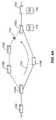
- FIG. 3is the communication network of FIG. 1 in which a service outage has occurred as a result of a failure and a first timestamp is established in accordance with an embodiment
- FIG. 4Ais the communication network of FIG. 1 in which service has been restored by rerouting data traffic and in which a second timestamp is established in accordance with an embodiment
- FIG. 4Bis the communication network of FIG. 1 in which service has been restored by rerouting data traffic and in which the second timestamp is established in accordance with another embodiment
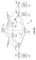
- FIG. 4Cis the communication network of FIG. 1 further including a collecting node for collecting service availability data
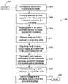
- FIG. 5is a flowchart showing the process for providing service availability data in accordance with an embodiment
- FIG. 6Ais a block diagram of an exemplary release message having an available information element for inserting a first timestamp
- FIG. 6Bis a block diagram of an exemplary connect confirmation message having an available information element for inserting a second timestamp.
- Network 100allows an originating or source node 102 to communicate with a destination node 104 through network cloud 106 . More specifically, the source node 102 is connected to a plurality of switching nodes 110 A . . . 110 E within network cloud 106 . Switching nodes 110 A . . . 110 E form the communication backbone of network cloud 106 . In turn, the plurality of switching nodes 110 A . . . 110 E are connected to the destination node 104 on the other side of network cloud 106 .
- the ports on the switching nodes 110 A . . . 110 Emay be physically interconnected by physical interconnectors or links 108 .
- the links 108may comprise, for example, standard physical interfaces such as OC-3, OC-12 or DS3.
- the links 108 between nodes 110 A . . . 110 Eallow a plurality of connections for communication sent between the source node 102 and the destination node 104 .
- one datapathis provided by nodes 110 A- 110 B- 110 C- 110 D and another datapath is provided by nodes 110 A- 110 E- 110 D.
- Routing tables associated with the nodes 110 A . . . 110 Eare configured to enable the source node 102 to communicate with the destination node 104 over the bearer channel.
- the bearer channelmay be a switched virtual circuit or SVC.
- the bearer channel, or any other physical link carrying the data trafficmay be referred to as a connection, a datapath or a circuit. It will be appreciated that a logical connection may be referred to as a routing path.
- an alternative datapathis provided by nodes 110 A- 110 E- 110 D but the links in the alternative datapath are shown as dashed lines to indicate that they are not currently being used.
- Each of nodes 110 A . . . 110 Emay comprise a call control and processing infrastructure for managing calls and implementing signalling protocols, and a connection manager which is responsible for creating and releasing cross-connects associated with the connection.
- the call control infrastructure disposed on the nodescommunicates over signalling links established between each successive pair of switches along the path of the SVC.
- the call control infrastructure and signalling linkscompose a signalling network operative to implement a signalling protocol.
- the ATM Forum Private Network-to-Network Interface (PNNI)may be used, as is well known in the art.
- the communication network of FIG. 1is shown with a fault 112 that has occurred on a link 108 between nodes 110 C and 110 D. Accordingly, any data traffic that was being routed through the datapath 110 A- 110 B- 110 C- 110 D has been interrupted.
- the time of occurrence of the link fault 112must be recorded, for example by a data timestamp, substantially contemporaneously with the actual occurrence of the fault 112 .
- substantially contemporaneous recordingmay be achieved by having a node immediately adjacent the link fault 112 (i.e. node 110 C) record the time of the fault 112 .
- a network event associated with the fault 112may also be recorded, as described further below.
- a timestampmay be a field having a time value therein associated with the event (i.e. fault 112 ).
- the timestampmay simply be an event stamp which is sent to a processing system which then associates a time with the event.
- a network clockis synchronized for all nodes operating in the communication network 100 using an appropriate protocol.
- NTPNetwork Time Protocol
- IETFInternet Engineering Task Force
- RFC- 1305Request for Comments document
- all nodesare synchronized to a common time, i.e. nodes that are physically located in different time zones are synchronized to one and the same network time.
- the common network timemay be based on co-ordinated universal time (UTC), formerly known as Greenwich Mean Time (GMT).
- nodes in a communication networkmay have different individual times but should be synchronized to the top of the hour, or to the half-hour as the case may be depending on the time zone.
- the respective time zoneswill also be recorded with the timestamp, so that time zone differences can be taken into account when calculating service outage times.
- each nodeneed not be synchronized to a common network time, to the top of the hour, or to the half-hour. Rather, each individual clock can keep its own time, but any relative time differences between the individual clocks must be communicated to a central node which co-ordinates time for all the nodes. (This embodiment is described in detail further below with reference to FIG. 4C .)
- node 110 C adjacent to the fault 112records a first timestamp TS 1 upon initial detection of the fault 112 .
- the fault 112is detected, for example, when the node 110 C detects a physical layer failure.
- the detection of fault 112also initiates a release by node 110 C, of any calls that were occurring across the datapath 110 C- 110 D at the time of the fault 112 , by generating and sending a connection release message 113 upstream to each of its connecting nodes for each connection.
- a similar release messagemay be sent downstream from node 110 D in case such a release message is useful for the destination node 104 .
- a release messagemay be used by destination node 104 in a network comprising multiple networks where multiple SLA are in place. Accordingly, the downstream release message may be used by another service provider.
- the connection release message 113may include a timestamp field in which the timestamp TS 1 is inserted (see FIG. 6A , below).
- the release message 113 and the timestamp TS 1are then sent upstream through the network elements to the originating node 102 .
- a second release message 113 ′may also be sent from node 110 D in the opposite direction in case the release message 113 ′ is useful for the destination node 104 . It will be appreciated that this may facilitate calculation of outage times for connections affected by the fault 112 but for data flow travelling in the opposite direction from node 104 towards node 102 .
- node 102When the release message 113 is received by the originating node 102 , node 102 proceeds to determine a new route (i.e. the alternative datapath 110 A- 110 E- 110 D) and attempts to re-establish a connection through to destination node 104 . Accordingly, once originating node 102 receives the release message 113 , it can extract the time of the fault TS 1 from the timestamp field of the release message 113 .
- the node 110 Cmay also record a first network event NE 1 associated with the fault 112 .
- the network event NE 1may provide additional information about the nature and location of fault 112 .
- NE 1may comprise an error code indicating whether the fault 112 is a software error or hardware error, and whether the fault 112 is actually located on the link 108 .
- any location information provided by the first network event NE 1may be used to determine from which node a subsequent second timestamp TS 2 or second network event NE 2 (see FIGS. 4A to 4C , below) is extracted and used, as described below.
- This selection between alternate nodes for retrieving the second timestamp TS 2need not occur immediately, but may be carried out at a later time once the various timestamps have been collected at a central node (see FIG. 4C , below).
- FIG. 4Athe communication network of FIG. 1 is shown with data traffic successfully routed through an alternate datapath 110 A- 110 E- 110 D in the general direction of arrow 114 , after the occurrence of fault 112 .
- a connect message 118(see FIG. 6B , below) confirming the new connection is generated by destination node 104 .
- a second timestamp TS 2is recorded by the destination node 104 , using one of the clock embodiments discussed above, in a timestamp field in the connect message 118 .
- the connect message 118may be generated by node 110 D when the node 110 D first recognizes that the datapath 110 A- 110 E- 110 D is up.
- an alternate second timestamp TS 2 ′may be recorded by node 110 D for insertion into a timestamp field in an alternate connect message 118 ′. It will be understood that, for certain network configurations and for certain protocols, recording the second timestamp TS 2 ′ at node 110 D may more accurately reflect the time at which service is restored for the purposes of calculating service outage time.
- the connect message 118 , 118 ′ containing the second timestamp TS 2 , TS 2 ′may be sent upstream to the originating node 102 , so that the originating node 102 receives both the first timestamp TS 1 and the second timestamp TS 2 , TS 2 ′ for calculating the service outage time.
- FIG. 4Bsimilar to FIG. 4A , the communication network 100 of FIG. 1 is shown with data traffic routed through an alternate datapath 110 A- 110 E- 110 D in the general direction of arrow 114 .
- a message confirming the new connectionis received by the originating node 102 , and a second timestamp TS 2 ′′ is recorded by the originating node 102 .
- This embodimentmay be appropriate where, for example, the network protocol dictates that the originating node does not attempt to transmit data until it receives notification that an alternate datapath (i.e. nodes 110 A- 110 E- 110 D) has been established.
- the selection from which node to extract the second timestamp TS 2 , TS 2 ′, TS 2 ′′depends on the particular network configuration and network protocol. In any event, the second timestamp TS 2 , TS 2 ′, TS 2 ′′ should reflect as closely as possible the actual time of service restoration in the network 100 .
- the selection of the node at which the second timestamp TS 2 is recordedmay be based on the nature and location of the fault 112 .
- Such informationmay be recorded, for example, as a first network event NE 1 in conjunction with the first timestamp TS 1
- FIG. 4Cthere is shown a network management station or a collection/control node 115 which is connected to other nodes 102 , 110 A, 110 B, 110 C, 110 D, 110 E, 104 in the communication network 100 by means of communication links 117 .
- the collection/control node 115may be another node in the communication network 100 connected through various links 108 .
- the communication links 117provide a communication path for timestamps TS 1 , TS 2 , TS 2 ′, TS 2 ′′ and network events NE 1 , NE 2 , etc. to be uploaded to the control node 115 from each of the other nodes 102 , 110 A, 110 B, 110 C, 110 D, 110 E, 104 .
- the individual nodes 102 , 110 A, 110 B, 110 C, 110 D, 110 E, 104need not be synchronized to a common network time.
- control node 115may be adapted to coordinate the relative time differences between the individual time clocks in nodes 102 , 110 A, 110 B, 110 C, 110 D, 110 E, 104 and to take such relative time differences into account when computing service outage times based on timestamps TS 1 , TS 2 , TS 2 ′, TS 2 ′′ received from the nodes 102 , 110 A, 110 B, 110 C, 110 D, 110 E, 104 .
- control node 115provides a dedicated resource for co-ordinating the time clocks and calculating the service outage times, thus reducing overhead on individual nodes in the network. Furthermore, uploading network events NE 1 , NE 2 to the control node 115 allows the control node 115 to provide more detailed information regarding each service outage and may even allow the control node 115 to select from which node an appropriate second timestamp TS 2 , TS 2 ′, TS 2 ′′ should be extracted for calculation of the service outage time.
- control node 115may not be possible for the control node 115 to have a dedicated communication link 117 to every other node.
- the control node 115may simply be another node in the communication network 100 having a specialized function, and having datapaths to the other nodes 102 , 110 A, 110 B, 110 C, 110 D, 110 E, 104 through various links 108 .
- any propagation, processing and queuing delay through the network 100 from the various nodes 102 , 110 A, 110 B, 110 C, 110 D, 110 E, 104 to the control node 115should not affect the calculation of service outage times based on the timestamps TS 1 , TS 2 , TS 2 ′, TS 2 ′′.
- FIG. 5generally indicated by reference numeral 500 is an example of a process for timestamping and calculating service level performance data in accordance with an embodiment of the invention.
- the process 500enters block 504 in which normal data transmission is taking place through a primary route (i.e. route 110 A- 110 B- 110 C- 110 D as previously described with reference to FIG. 2 ).
- Process 500then waits at block 508 until a failure is detected by a node adjacent to the failure.
- a first timestamp TS 1is recorded. This condition was shown previously in FIG. 3 .
- node 110 Cis the node immediately adjacent to the link failure 112 .
- Node 110 Crecords the time that it detects the failure 112 with a first timestamp TS 1 using one of the timing protocols, for example NTP, as described above.
- TS 1indicates the time at which service is first interrupted.
- the process 500then proceeds to block 510 where the adjacent node 110 C generates a release message 113 ( FIG. 3 , above), and sends this release message 113 together with TS 1 upstream towards the originating node 102 , in the general direction of arrow 116 ( FIG. 3 , above).
- Each of nodes 110 A and 110 Balso receive the release message 113 and TS 1 en route back to the originating node 102 . While the network 100 shown by way of example in FIGS. 1-4 has been simplified for clarity, it will be understood that nodes 110 A and 110 B may be originating nodes for other channels (connected by nodes and links not shown) and may make use of the release message 113 and the first timestamp TS 1 .
- FIG. 4Ashows the establishment of an alternate route ( 110 A- 110 E- 110 D) from the originating node 102 to the destination node 104 .
- the process 500then proceeds to block 514 where the destination node 104 receives confirmation of the new connection (i.e. the alternate route) as it begins to receive data from the originating node 102 (through node 110 D).
- the destination node 104Upon establishment of the new connection, the destination node 104 generates a connect message 118 ( FIG. 4A ) and records a second timestamp TS 2 using the common network clock described above.
- TS 2indicates the time at which the destination node 104 recognizes that service from the originating node 102 has resumed.
- the process 500proceeds to block 515 where the connect message 118 is sent upstream to the originating node 102 .
- the process 500then proceeds to block 516 wherein the process 500 calculates the total service outage time based on TS 1 and TS 2 (extracted from the release message 113 and connect message 118 , respectively). If an absolute time clock has been used, such as UTC, the service outage time is calculated as TS 2 -TS 1 . If relative time clocks have been used together with information on the relative time zones of the nodes, then the difference in time zones must be taken into account in the calculation. For example, the timestamps TS 1 and TS 2 may be converted to UTC before calculating TS 2 -TS 1 .
- TS 1 and TS 2are communicated to a separate network element (collection node 115 of FIG. 4C ) that receives such timestamp information and calculates the service outage times as described above.
- the service availability data based on the time stamps TS 1 , TS 2is calculated for each particular customer connection with whom a service provider has an SLA.
- the second time stamp TS 2need not be recorded at the destination node 104 . Rather, an alternate second timestamp TS 2 ′ may be recorded at a more suitable intermediate node (e.g. node 10 D of FIG. 4B ) so that the second timestamp TS 2 ′ is more reflective of the actual time of restoration of service.
- the first time stamp TS 1may be sent towards the intermediate node 110 D instead of the originating node 102 so that node 110 D is instead responsible for performing the actual reporting of outage time based on TS 1 and TS 2 ′.
- the second timestamp TS 2 ′′may be recorded at the originating node 102 itself, should this more closely reflect the actual time of restoration of service. As noted above, this last mentioned embodiment may be most suitable if the network protocol dictates that data cannot be sent until the originating node itself receives the connect message.
- the embodiment described aboverecords the first timestamp TS 1 at the time a node immediately adjacent to a failure detects the failure. This insures an accurate service outage start time which is consistent for all connections affected by the particular network failure, regardless of any potential propagation, queuing or processing delays in the network 100 .
- the second timestamp TS 2is recorded at a time an affected node receives confirmation of a new connection.
- a unique ‘second’ timestamp TS 2 , TS 2 ′may be recorded at each node affected by the failure such that there are a plurality of second timestamps TS 2 , TS 2 ′ in the network 100 .
- selection of which node to extract the second timestamp frommay be based on the particular network configuration and network protocol, such that the second timestamp TS 2 , TS 2 ′ most closely reflects the actual time of restoration of service. Consequently, the calculation according to the embodiment is designed to accurately reflect the actual amount of time that service is disrupted in the network 100 for a particular connection originating at a particular node, and ending at a particular destination node.
- the recording of TS 1 by a node immediately adjacent to a failureprovides a more accurate timestamp than propagating a failure signal across multiple network elements between the failure and the originating node and then recording the time of receipt of the failure signal.
- the recording of TS 2 at a suitably chosen affected nodeupon recognition of a new connection by that affected node, accurately reflects the time at which service can actually resume.
- the embodimentmay make use of an empty field in a release message 113 which does not require separate processing and transmission of TS 1 .
- the release messagemay have a standard IE (information element) defined in terms of type, length and value, and TS 1 may be inserted into such an empty field.
- the empty field for inserting a timestampis identified by reference numeral 610 A.
- Various other fields 602 A, 604 A, 606 A, 608 A, 612 Amay include information relating to message type, network call ID, cause code, network event code, and vendor specific code, etc.
- any overhead traffic in the network 100 associated with the embodimentis designed to be minimized, as the release message 113 is typically already a part of the network protocol.
- the release message in the ATM Forum PNNI protocolincludes an IE to which vendor specific sub-IE's may be added.
- the embodimentmay make use of an available empty field (timestamp field 610 B in FIG. 6B ) in the connect message 118 to insert TS 2 .
- the connect message 118may also have various other fields 602 B, 604 B, 606 B, 608 B, which include information relating to message type, network call ID, cause code, and network event code, etc.
- the connect message in the ATM Forum PNNI protocolmay be used for this purpose, similar to the release message described above.
Landscapes
- Engineering & Computer Science (AREA)
- Computer Networks & Wireless Communication (AREA)
- Signal Processing (AREA)
- Computer Security & Cryptography (AREA)
- Environmental & Geological Engineering (AREA)
- Physics & Mathematics (AREA)
- Probability & Statistics with Applications (AREA)
- Data Exchanges In Wide-Area Networks (AREA)
Abstract
Description
Claims (11)
Priority Applications (4)
| Application Number | Priority Date | Filing Date | Title |
|---|---|---|---|
| US10/012,428US7426573B2 (en) | 2001-12-12 | 2001-12-12 | System and method for providing service availability data for a communication network |
| CNB021471568ACN100450227C (en) | 2001-12-12 | 2002-10-24 | System and method for providing service availability data for a communication network |
| EP02293032AEP1322098B1 (en) | 2001-12-12 | 2002-12-06 | System and method for providing service availability data for a communication network |
| DE60207967TDE60207967T2 (en) | 2001-12-12 | 2002-12-06 | A system and method for providing service availability data of a communications network |
Applications Claiming Priority (1)
| Application Number | Priority Date | Filing Date | Title |
|---|---|---|---|
| US10/012,428US7426573B2 (en) | 2001-12-12 | 2001-12-12 | System and method for providing service availability data for a communication network |
Publications (2)
| Publication Number | Publication Date |
|---|---|
| US20030110408A1 US20030110408A1 (en) | 2003-06-12 |
| US7426573B2true US7426573B2 (en) | 2008-09-16 |
Family
ID=21754927
Family Applications (1)
| Application Number | Title | Priority Date | Filing Date |
|---|---|---|---|
| US10/012,428Expired - Fee RelatedUS7426573B2 (en) | 2001-12-12 | 2001-12-12 | System and method for providing service availability data for a communication network |
Country Status (4)
| Country | Link |
|---|---|
| US (1) | US7426573B2 (en) |
| EP (1) | EP1322098B1 (en) |
| CN (1) | CN100450227C (en) |
| DE (1) | DE60207967T2 (en) |
Cited By (4)
| Publication number | Priority date | Publication date | Assignee | Title |
|---|---|---|---|---|
| US20050169240A1 (en)* | 2004-02-02 | 2005-08-04 | Balaji Bal | Routing system |
| US20060069786A1 (en)* | 2004-09-24 | 2006-03-30 | Mogul Jeffrey C | System and method for ascribing resource consumption to activity in a causal path of a node of a distributed computing system |
| US20090190481A1 (en)* | 2006-09-15 | 2009-07-30 | Fujitsu Limited | Route confirmation method and device |
| US20110208953A1 (en)* | 2010-02-19 | 2011-08-25 | James Solomon | Event time management in an electric vehicle charging station without a battery-backed real time clock |
Families Citing this family (34)
| Publication number | Priority date | Publication date | Assignee | Title |
|---|---|---|---|---|
| US7711855B2 (en)* | 2002-06-19 | 2010-05-04 | Siebel Systems, Inc. | Method and device for processing a time-related data entry |
| US7197668B1 (en)* | 2002-09-16 | 2007-03-27 | Cisco Technology, Inc. | Network wide debugging including node debugging information in the GAT IE of a PNNI Signaling Message |
| US7254646B2 (en)* | 2003-06-23 | 2007-08-07 | Hewlett-Packard Development Company, L.P. | Analysis of causal relations between intercommunicating nodes |
| GB0321641D0 (en)* | 2003-09-16 | 2003-10-15 | Agilent Technologies Inc | Methods and apparatus for measuring service disruption |
| KR100652681B1 (en)* | 2004-10-08 | 2006-12-07 | 엘지전자 주식회사 | Waiting device and method for waiting in mobile terminal |
| US20110082928A1 (en)* | 2004-10-22 | 2011-04-07 | Microsoft Corporation | Maintaining consistency within a federation infrastructure |
| US8095600B2 (en)* | 2004-10-22 | 2012-01-10 | Microsoft Corporation | Inter-proximity communication within a rendezvous federation |
| US20060090003A1 (en)* | 2004-10-22 | 2006-04-27 | Microsoft Corporation | Rendezvousing resource requests with corresponding resources |
| US7694167B2 (en)* | 2004-10-22 | 2010-04-06 | Microsoft Corporation | Maintaining routing consistency within a rendezvous federation |
| US8549180B2 (en)* | 2004-10-22 | 2013-10-01 | Microsoft Corporation | Optimizing access to federation infrastructure-based resources |
| US8095601B2 (en)* | 2004-10-22 | 2012-01-10 | Microsoft Corporation | Inter-proximity communication within a rendezvous federation |
| US20080288659A1 (en) | 2006-11-09 | 2008-11-20 | Microsoft Corporation | Maintaining consistency within a federation infrastructure |
| US7958262B2 (en)* | 2004-10-22 | 2011-06-07 | Microsoft Corporation | Allocating and reclaiming resources within a rendezvous federation |
| US8014321B2 (en)* | 2004-10-22 | 2011-09-06 | Microsoft Corporation | Rendezvousing resource requests with corresponding resources |
| US8392515B2 (en)* | 2004-10-22 | 2013-03-05 | Microsoft Corporation | Subfederation creation and maintenance in a federation infrastructure |
| US7730220B2 (en)* | 2004-10-22 | 2010-06-01 | Microsoft Corporation | Broadcasting communication within a rendezvous federation |
| US7487403B2 (en)* | 2004-11-12 | 2009-02-03 | International Business Machines Corporation | Method for handling a device failure |
| CN100401826C (en)* | 2005-03-31 | 2008-07-09 | 华为技术有限公司 | Fault Detection Method of Transmission Link |
| US7801997B2 (en)* | 2006-03-30 | 2010-09-21 | International Business Machines Corporation | Asynchronous interconnect protocol for a clustered DBMS |
| EP2367309B1 (en)* | 2010-02-10 | 2016-07-13 | Alcatel Lucent | Method for detecting a synchronization failure of a transparent clock and related protection schemes |
| CN102215141A (en)* | 2010-04-02 | 2011-10-12 | 华为技术有限公司 | Method and system for interruption measurement and monitoring equipment |
| CN102215139A (en)* | 2010-04-02 | 2011-10-12 | 华为技术有限公司 | Interruption measuring method, device and system |
| CN103220081B (en)* | 2012-01-21 | 2017-04-05 | 华为技术有限公司 | Collision detection method, network equipment and user equipment |
| US9229800B2 (en) | 2012-06-28 | 2016-01-05 | Microsoft Technology Licensing, Llc | Problem inference from support tickets |
| US9262253B2 (en) | 2012-06-28 | 2016-02-16 | Microsoft Technology Licensing, Llc | Middlebox reliability |
| US9565080B2 (en) | 2012-11-15 | 2017-02-07 | Microsoft Technology Licensing, Llc | Evaluating electronic network devices in view of cost and service level considerations |
| US9325748B2 (en)* | 2012-11-15 | 2016-04-26 | Microsoft Technology Licensing, Llc | Characterizing service levels on an electronic network |
| US9706508B2 (en)* | 2013-04-05 | 2017-07-11 | Honeywell International Inc. | Integrated avionics systems and methods |
| US9350601B2 (en) | 2013-06-21 | 2016-05-24 | Microsoft Technology Licensing, Llc | Network event processing and prioritization |
| US20150244874A1 (en)* | 2014-02-24 | 2015-08-27 | Telefonaktiebolaget L M Ericsson (Publ) | Method and Apparatus for Managing Charging in Communication Networks |
| WO2016013529A1 (en) | 2014-07-22 | 2016-01-28 | 株式会社リコー | Control system, communication terminal, communication system, control method, and program |
| WO2016114270A1 (en) | 2015-01-15 | 2016-07-21 | 株式会社リコー | Control system, communication terminal, communication system, control method, and program |
| JP2016146565A (en)* | 2015-02-09 | 2016-08-12 | 株式会社リコー | Management system, communication system, management method, and program |
| JP6536068B2 (en) | 2015-02-19 | 2019-07-03 | 株式会社リコー | Control system, communication system, control method, and program |
Citations (17)
| Publication number | Priority date | Publication date | Assignee | Title |
|---|---|---|---|---|
| US5276440A (en)* | 1989-02-16 | 1994-01-04 | International Business Machines Corporation | Network device information exchange |
| US5627766A (en)* | 1994-02-08 | 1997-05-06 | International Business Machines Corporation | Performance and status monitoring in a computer network |
| US5745693A (en) | 1992-07-01 | 1998-04-28 | Mci Corporation | System for gathering and reporting real time data from an IDNX communications network |
| US5790431A (en)* | 1995-11-20 | 1998-08-04 | International Business Machines Corporation | Method and system for measuring availability in a distributed network |
| US5841972A (en)* | 1997-01-03 | 1998-11-24 | Ncr Corporation | System using displayed configuration utility on monitor including list of target nodes, for administering interconnected nodes of computer network |
| US6229787B1 (en)* | 1996-09-11 | 2001-05-08 | Nortel Networks Limited | Mechanism to achieve very fast failover in ATM backbone networks using multi-homed circuits |
| US6272107B1 (en)* | 1998-05-12 | 2001-08-07 | 3Com Corporation | Method of path restoration in an ATM network utilizing point to point switched virtual circuits |
| US6295541B1 (en)* | 1997-12-16 | 2001-09-25 | Starfish Software, Inc. | System and methods for synchronizing two or more datasets |
| US6304549B1 (en)* | 1996-09-12 | 2001-10-16 | Lucent Technologies Inc. | Virtual path management in hierarchical ATM networks |
| US6385198B1 (en)* | 1998-06-11 | 2002-05-07 | Synchrodyne Networks, Inc. | Signaling for timely forwarding in packet switching network with a common time reference |
| US6446058B1 (en)* | 1999-04-26 | 2002-09-03 | At&T Corp. | Computer platform alarm and control system |
| US20020131362A1 (en)* | 2001-03-16 | 2002-09-19 | Ross Callon | Network routing using link failure information |
| US6574244B1 (en)* | 1998-11-04 | 2003-06-03 | Trimble Navigation Limited | Determining time stamps in a data acquisition system |
| US6594786B1 (en)* | 2000-01-31 | 2003-07-15 | Hewlett-Packard Development Company, Lp | Fault tolerant high availability meter |
| US20030149919A1 (en)* | 2000-05-05 | 2003-08-07 | Joseph Greenwald | Systems and methods for diagnosing faults in computer networks |
| US6608817B1 (en)* | 1999-12-28 | 2003-08-19 | Networks Associates Technology, Inc. | Method and apparatus for connection-oriented multiplexing and switching network analysis, management, and troubleshooting |
| US6643267B1 (en)* | 1999-06-30 | 2003-11-04 | Cisco Technology, Inc. | Method and apparatus for tracing a virtual connection |
- 2001
- 2001-12-12USUS10/012,428patent/US7426573B2/ennot_activeExpired - Fee Related
- 2002
- 2002-10-24CNCNB021471568Apatent/CN100450227C/ennot_activeExpired - Fee Related
- 2002-12-06DEDE60207967Tpatent/DE60207967T2/ennot_activeExpired - Lifetime
- 2002-12-06EPEP02293032Apatent/EP1322098B1/ennot_activeExpired - Lifetime
Patent Citations (17)
| Publication number | Priority date | Publication date | Assignee | Title |
|---|---|---|---|---|
| US5276440A (en)* | 1989-02-16 | 1994-01-04 | International Business Machines Corporation | Network device information exchange |
| US5745693A (en) | 1992-07-01 | 1998-04-28 | Mci Corporation | System for gathering and reporting real time data from an IDNX communications network |
| US5627766A (en)* | 1994-02-08 | 1997-05-06 | International Business Machines Corporation | Performance and status monitoring in a computer network |
| US5790431A (en)* | 1995-11-20 | 1998-08-04 | International Business Machines Corporation | Method and system for measuring availability in a distributed network |
| US6229787B1 (en)* | 1996-09-11 | 2001-05-08 | Nortel Networks Limited | Mechanism to achieve very fast failover in ATM backbone networks using multi-homed circuits |
| US6304549B1 (en)* | 1996-09-12 | 2001-10-16 | Lucent Technologies Inc. | Virtual path management in hierarchical ATM networks |
| US5841972A (en)* | 1997-01-03 | 1998-11-24 | Ncr Corporation | System using displayed configuration utility on monitor including list of target nodes, for administering interconnected nodes of computer network |
| US6295541B1 (en)* | 1997-12-16 | 2001-09-25 | Starfish Software, Inc. | System and methods for synchronizing two or more datasets |
| US6272107B1 (en)* | 1998-05-12 | 2001-08-07 | 3Com Corporation | Method of path restoration in an ATM network utilizing point to point switched virtual circuits |
| US6385198B1 (en)* | 1998-06-11 | 2002-05-07 | Synchrodyne Networks, Inc. | Signaling for timely forwarding in packet switching network with a common time reference |
| US6574244B1 (en)* | 1998-11-04 | 2003-06-03 | Trimble Navigation Limited | Determining time stamps in a data acquisition system |
| US6446058B1 (en)* | 1999-04-26 | 2002-09-03 | At&T Corp. | Computer platform alarm and control system |
| US6643267B1 (en)* | 1999-06-30 | 2003-11-04 | Cisco Technology, Inc. | Method and apparatus for tracing a virtual connection |
| US6608817B1 (en)* | 1999-12-28 | 2003-08-19 | Networks Associates Technology, Inc. | Method and apparatus for connection-oriented multiplexing and switching network analysis, management, and troubleshooting |
| US6594786B1 (en)* | 2000-01-31 | 2003-07-15 | Hewlett-Packard Development Company, Lp | Fault tolerant high availability meter |
| US20030149919A1 (en)* | 2000-05-05 | 2003-08-07 | Joseph Greenwald | Systems and methods for diagnosing faults in computer networks |
| US20020131362A1 (en)* | 2001-03-16 | 2002-09-19 | Ross Callon | Network routing using link failure information |
Non-Patent Citations (1)
| Title |
|---|
| Wang et al. IP Multicast Fault Recovery in PIM over OSPF. ACM Sigmetrics Performance Evaluation Review. vol. 28. Issue 1. Jun. 2000. pp. 106-107.* |
Cited By (8)
| Publication number | Priority date | Publication date | Assignee | Title |
|---|---|---|---|---|
| US20050169240A1 (en)* | 2004-02-02 | 2005-08-04 | Balaji Bal | Routing system |
| US7818451B2 (en)* | 2004-02-02 | 2010-10-19 | Surfkitchen, Inc. | Routing system |
| US20060069786A1 (en)* | 2004-09-24 | 2006-03-30 | Mogul Jeffrey C | System and method for ascribing resource consumption to activity in a causal path of a node of a distributed computing system |
| US8364829B2 (en)* | 2004-09-24 | 2013-01-29 | Hewlett-Packard Development Company, L.P. | System and method for ascribing resource consumption to activity in a causal path of a node of a distributed computing system |
| US20090190481A1 (en)* | 2006-09-15 | 2009-07-30 | Fujitsu Limited | Route confirmation method and device |
| US8018836B2 (en)* | 2006-09-15 | 2011-09-13 | Fujitsu Limited | Route confirmation method and device |
| US20110208953A1 (en)* | 2010-02-19 | 2011-08-25 | James Solomon | Event time management in an electric vehicle charging station without a battery-backed real time clock |
| US8250398B2 (en)* | 2010-02-19 | 2012-08-21 | Coulomb Technologies, Inc. | Event time management in an electric vehicle charging station without a battery-backed real time clock |
Also Published As
| Publication number | Publication date |
|---|---|
| US20030110408A1 (en) | 2003-06-12 |
| DE60207967T2 (en) | 2006-08-17 |
| EP1322098A3 (en) | 2004-01-28 |
| EP1322098B1 (en) | 2005-12-14 |
| DE60207967D1 (en) | 2006-01-19 |
| CN1426253A (en) | 2003-06-25 |
| EP1322098A2 (en) | 2003-06-25 |
| CN100450227C (en) | 2009-01-07 |
Similar Documents
| Publication | Publication Date | Title |
|---|---|---|
| US7426573B2 (en) | System and method for providing service availability data for a communication network | |
| JP3894232B2 (en) | ATM switch performance monitoring | |
| US5878032A (en) | Delay monitoring of telecommunication networks | |
| AU749143B2 (en) | Next hop loopback | |
| KR100833510B1 (en) | Method and Apparatus for measurement of LSP performance parameters using MPLS OAM packet | |
| US6545979B1 (en) | Round trip delay measurement | |
| US7835290B2 (en) | Method for measuring end-to-end delay in asynchronous packet transfer network, and asynchronous packet transmitter and receiver | |
| US7995572B2 (en) | Communication path monitoring system and communication network system | |
| US7092361B2 (en) | System and method for transmission of operations, administration and maintenance packets between ATM and switching networks upon failures | |
| GB2337895A (en) | Detecting congestion in ATM networks | |
| EP2624506A1 (en) | Route control method and system, and route computing apparatus | |
| JP2000174755A (en) | Route selection method | |
| US20060092941A1 (en) | Communication path monitoring system and communication network system | |
| Jiang et al. | Challenges and approaches in providing QoS monitoring | |
| EP1309125B1 (en) | Method and system for determining availability in communication networks via transmission of monitoring packets | |
| US9306822B2 (en) | Method and system for silent trunk failure detection | |
| JPH1127269A (en) | Clock synchronization method and apparatus and recording medium | |
| CN1983908B (en) | A self-correcting method for tag resource management | |
| JPWO2002067503A1 (en) | Communication quality management system, communication quality management method, program and recording medium | |
| Yoshikai et al. | Control protocol and its performance analysis for distributed ATM virtual path self-healing network | |
| Gruber | Performance and fault management functions for the maintenance of SONET/SDH and ATM transport networks | |
| EP1215856B1 (en) | Billing redundant ATM connections | |
| JP3049301B2 (en) | Failure recovery and congestion recovery in connection-oriented communication networks | |
| JP2001230776A (en) | Switching device, difference information collecting device, communication network system, and communication method | |
| JP2001313649A (en) | Network system and connection switching method |
Legal Events
| Date | Code | Title | Description |
|---|---|---|---|
| AS | Assignment | Owner name:ALCATEL CANADA INC., CANADA Free format text:ASSIGNMENT OF ASSIGNORS INTEREST;ASSIGNORS:WELLS, DONALD J.;DIPPEL, PETER C.;MCALLISTER, SHAWN;REEL/FRAME:012381/0425 Effective date:20011205 | |
| AS | Assignment | Owner name:ALCATEL LUCENT, FRANCE Free format text:CHANGE OF NAME;ASSIGNOR:ALCATEL;REEL/FRAME:021368/0455 Effective date:20061130 | |
| STCF | Information on status: patent grant | Free format text:PATENTED CASE | |
| FPAY | Fee payment | Year of fee payment:4 | |
| AS | Assignment | Owner name:CREDIT SUISSE AG, NEW YORK Free format text:SECURITY AGREEMENT;ASSIGNOR:LUCENT, ALCATEL;REEL/FRAME:029821/0001 Effective date:20130130 Owner name:CREDIT SUISSE AG, NEW YORK Free format text:SECURITY AGREEMENT;ASSIGNOR:ALCATEL LUCENT;REEL/FRAME:029821/0001 Effective date:20130130 | |
| AS | Assignment | Owner name:ALCATEL LUCENT, FRANCE Free format text:RELEASE BY SECURED PARTY;ASSIGNOR:CREDIT SUISSE AG;REEL/FRAME:033868/0001 Effective date:20140819 | |
| AS | Assignment | Owner name:ALCATEL-LUCENT CANADA INC., CANADA Free format text:MERGER;ASSIGNORS:ALCATEL CANADA INC.;LUCENT TECHNOLOGIES CANADA CORP.;REEL/FRAME:034107/0195 Effective date:20070101 | |
| FPAY | Fee payment | Year of fee payment:8 | |
| AS | Assignment | Owner name:OMEGA CREDIT OPPORTUNITIES MASTER FUND, LP, NEW YORK Free format text:SECURITY INTEREST;ASSIGNOR:WSOU INVESTMENTS, LLC;REEL/FRAME:043966/0574 Effective date:20170822 Owner name:OMEGA CREDIT OPPORTUNITIES MASTER FUND, LP, NEW YO Free format text:SECURITY INTEREST;ASSIGNOR:WSOU INVESTMENTS, LLC;REEL/FRAME:043966/0574 Effective date:20170822 | |
| AS | Assignment | Owner name:WSOU INVESTMENTS, LLC, CALIFORNIA Free format text:ASSIGNMENT OF ASSIGNORS INTEREST;ASSIGNOR:ALCATEL LUCENT;REEL/FRAME:044000/0053 Effective date:20170722 | |
| AS | Assignment | Owner name:BP FUNDING TRUST, SERIES SPL-VI, NEW YORK Free format text:SECURITY INTEREST;ASSIGNOR:WSOU INVESTMENTS, LLC;REEL/FRAME:049235/0068 Effective date:20190516 | |
| AS | Assignment | Owner name:WSOU INVESTMENTS, LLC, CALIFORNIA Free format text:RELEASE BY SECURED PARTY;ASSIGNOR:OCO OPPORTUNITIES MASTER FUND, L.P. (F/K/A OMEGA CREDIT OPPORTUNITIES MASTER FUND LP;REEL/FRAME:049246/0405 Effective date:20190516 | |
| FEPP | Fee payment procedure | Free format text:MAINTENANCE FEE REMINDER MAILED (ORIGINAL EVENT CODE: REM.); ENTITY STATUS OF PATENT OWNER: LARGE ENTITY | |
| LAPS | Lapse for failure to pay maintenance fees | Free format text:PATENT EXPIRED FOR FAILURE TO PAY MAINTENANCE FEES (ORIGINAL EVENT CODE: EXP.); ENTITY STATUS OF PATENT OWNER: LARGE ENTITY | |
| STCH | Information on status: patent discontinuation | Free format text:PATENT EXPIRED DUE TO NONPAYMENT OF MAINTENANCE FEES UNDER 37 CFR 1.362 | |
| FP | Lapsed due to failure to pay maintenance fee | Effective date:20200916 | |
| AS | Assignment | Owner name:OT WSOU TERRIER HOLDINGS, LLC, CALIFORNIA Free format text:SECURITY INTEREST;ASSIGNOR:WSOU INVESTMENTS, LLC;REEL/FRAME:056990/0081 Effective date:20210528 | |
| AS | Assignment | Owner name:WSOU INVESTMENTS, LLC, CALIFORNIA Free format text:RELEASE BY SECURED PARTY;ASSIGNOR:TERRIER SSC, LLC;REEL/FRAME:056526/0093 Effective date:20210528 |