US7425294B2 - Plastic skin forming process - Google Patents
Plastic skin forming processDownload PDFInfo
- Publication number
- US7425294B2 US7425294B2US10/433,361US43336103AUS7425294B2US 7425294 B2US7425294 B2US 7425294B2US 43336103 AUS43336103 AUS 43336103AUS 7425294 B2US7425294 B2US 7425294B2
- Authority
- US
- United States
- Prior art keywords
- mold
- back surface
- plastic
- infrared energy
- metal mold
- Prior art date
- Legal status (The legal status is an assumption and is not a legal conclusion. Google has not performed a legal analysis and makes no representation as to the accuracy of the status listed.)
- Expired - Lifetime
Links
Images


Classifications
- B—PERFORMING OPERATIONS; TRANSPORTING
- B29—WORKING OF PLASTICS; WORKING OF SUBSTANCES IN A PLASTIC STATE IN GENERAL
- B29C—SHAPING OR JOINING OF PLASTICS; SHAPING OF MATERIAL IN A PLASTIC STATE, NOT OTHERWISE PROVIDED FOR; AFTER-TREATMENT OF THE SHAPED PRODUCTS, e.g. REPAIRING
- B29C41/00—Shaping by coating a mould, core or other substrate, i.e. by depositing material and stripping-off the shaped article; Apparatus therefor
- B29C41/34—Component parts, details or accessories; Auxiliary operations
- B29C41/46—Heating or cooling
- B—PERFORMING OPERATIONS; TRANSPORTING
- B29—WORKING OF PLASTICS; WORKING OF SUBSTANCES IN A PLASTIC STATE IN GENERAL
- B29C—SHAPING OR JOINING OF PLASTICS; SHAPING OF MATERIAL IN A PLASTIC STATE, NOT OTHERWISE PROVIDED FOR; AFTER-TREATMENT OF THE SHAPED PRODUCTS, e.g. REPAIRING
- B29C33/00—Moulds or cores; Details thereof or accessories therefor
- B29C33/56—Coatings, e.g. enameled or galvanised; Releasing, lubricating or separating agents
- B—PERFORMING OPERATIONS; TRANSPORTING
- B29—WORKING OF PLASTICS; WORKING OF SUBSTANCES IN A PLASTIC STATE IN GENERAL
- B29C—SHAPING OR JOINING OF PLASTICS; SHAPING OF MATERIAL IN A PLASTIC STATE, NOT OTHERWISE PROVIDED FOR; AFTER-TREATMENT OF THE SHAPED PRODUCTS, e.g. REPAIRING
- B29C41/00—Shaping by coating a mould, core or other substrate, i.e. by depositing material and stripping-off the shaped article; Apparatus therefor
- B29C41/02—Shaping by coating a mould, core or other substrate, i.e. by depositing material and stripping-off the shaped article; Apparatus therefor for making articles of definite length, i.e. discrete articles
- B29C41/08—Coating a former, core or other substrate by spraying or fluidisation, e.g. spraying powder
- B—PERFORMING OPERATIONS; TRANSPORTING
- B29—WORKING OF PLASTICS; WORKING OF SUBSTANCES IN A PLASTIC STATE IN GENERAL
- B29C—SHAPING OR JOINING OF PLASTICS; SHAPING OF MATERIAL IN A PLASTIC STATE, NOT OTHERWISE PROVIDED FOR; AFTER-TREATMENT OF THE SHAPED PRODUCTS, e.g. REPAIRING
- B29C41/00—Shaping by coating a mould, core or other substrate, i.e. by depositing material and stripping-off the shaped article; Apparatus therefor
- B29C41/02—Shaping by coating a mould, core or other substrate, i.e. by depositing material and stripping-off the shaped article; Apparatus therefor for making articles of definite length, i.e. discrete articles
- B29C41/18—Slush casting, i.e. pouring moulding material into a hollow mould with excess material being poured off
- B—PERFORMING OPERATIONS; TRANSPORTING
- B29—WORKING OF PLASTICS; WORKING OF SUBSTANCES IN A PLASTIC STATE IN GENERAL
- B29C—SHAPING OR JOINING OF PLASTICS; SHAPING OF MATERIAL IN A PLASTIC STATE, NOT OTHERWISE PROVIDED FOR; AFTER-TREATMENT OF THE SHAPED PRODUCTS, e.g. REPAIRING
- B29C45/00—Injection moulding, i.e. forcing the required volume of moulding material through a nozzle into a closed mould; Apparatus therefor
- B29C45/14—Injection moulding, i.e. forcing the required volume of moulding material through a nozzle into a closed mould; Apparatus therefor incorporating preformed parts or layers, e.g. injection moulding around inserts or for coating articles
- B29C45/14639—Injection moulding, i.e. forcing the required volume of moulding material through a nozzle into a closed mould; Apparatus therefor incorporating preformed parts or layers, e.g. injection moulding around inserts or for coating articles for obtaining an insulating effect, e.g. for electrical components
- B29C45/14655—Injection moulding, i.e. forcing the required volume of moulding material through a nozzle into a closed mould; Apparatus therefor incorporating preformed parts or layers, e.g. injection moulding around inserts or for coating articles for obtaining an insulating effect, e.g. for electrical components connected to or mounted on a carrier, e.g. lead frame
- B—PERFORMING OPERATIONS; TRANSPORTING
- B29—WORKING OF PLASTICS; WORKING OF SUBSTANCES IN A PLASTIC STATE IN GENERAL
- B29C—SHAPING OR JOINING OF PLASTICS; SHAPING OF MATERIAL IN A PLASTIC STATE, NOT OTHERWISE PROVIDED FOR; AFTER-TREATMENT OF THE SHAPED PRODUCTS, e.g. REPAIRING
- B29C48/00—Extrusion moulding, i.e. expressing the moulding material through a die or nozzle which imparts the desired form; Apparatus therefor
- B29C48/03—Extrusion moulding, i.e. expressing the moulding material through a die or nozzle which imparts the desired form; Apparatus therefor characterised by the shape of the extruded material at extrusion
- B29C48/12—Articles with an irregular circumference when viewed in cross-section, e.g. window profiles
- B—PERFORMING OPERATIONS; TRANSPORTING
- B29—WORKING OF PLASTICS; WORKING OF SUBSTANCES IN A PLASTIC STATE IN GENERAL
- B29C—SHAPING OR JOINING OF PLASTICS; SHAPING OF MATERIAL IN A PLASTIC STATE, NOT OTHERWISE PROVIDED FOR; AFTER-TREATMENT OF THE SHAPED PRODUCTS, e.g. REPAIRING
- B29C48/00—Extrusion moulding, i.e. expressing the moulding material through a die or nozzle which imparts the desired form; Apparatus therefor
- B29C48/03—Extrusion moulding, i.e. expressing the moulding material through a die or nozzle which imparts the desired form; Apparatus therefor characterised by the shape of the extruded material at extrusion
- B29C48/13—Articles with a cross-section varying in the longitudinal direction, e.g. corrugated pipes
- B—PERFORMING OPERATIONS; TRANSPORTING
- B29—WORKING OF PLASTICS; WORKING OF SUBSTANCES IN A PLASTIC STATE IN GENERAL
- B29C—SHAPING OR JOINING OF PLASTICS; SHAPING OF MATERIAL IN A PLASTIC STATE, NOT OTHERWISE PROVIDED FOR; AFTER-TREATMENT OF THE SHAPED PRODUCTS, e.g. REPAIRING
- B29C48/00—Extrusion moulding, i.e. expressing the moulding material through a die or nozzle which imparts the desired form; Apparatus therefor
- B29C48/25—Component parts, details or accessories; Auxiliary operations
- B29C48/88—Thermal treatment of the stream of extruded material, e.g. cooling
- B29C48/90—Thermal treatment of the stream of extruded material, e.g. cooling with calibration or sizing, i.e. combined with fixing or setting of the final dimensions of the extruded article
- B29C48/904—Thermal treatment of the stream of extruded material, e.g. cooling with calibration or sizing, i.e. combined with fixing or setting of the final dimensions of the extruded article using dry calibration, i.e. no quenching tank, e.g. with water spray for cooling or lubrication
- B—PERFORMING OPERATIONS; TRANSPORTING
- B29—WORKING OF PLASTICS; WORKING OF SUBSTANCES IN A PLASTIC STATE IN GENERAL
- B29C—SHAPING OR JOINING OF PLASTICS; SHAPING OF MATERIAL IN A PLASTIC STATE, NOT OTHERWISE PROVIDED FOR; AFTER-TREATMENT OF THE SHAPED PRODUCTS, e.g. REPAIRING
- B29C48/00—Extrusion moulding, i.e. expressing the moulding material through a die or nozzle which imparts the desired form; Apparatus therefor
- B29C48/25—Component parts, details or accessories; Auxiliary operations
- B29C48/88—Thermal treatment of the stream of extruded material, e.g. cooling
- B29C48/911—Cooling
- B—PERFORMING OPERATIONS; TRANSPORTING
- B29—WORKING OF PLASTICS; WORKING OF SUBSTANCES IN A PLASTIC STATE IN GENERAL
- B29C—SHAPING OR JOINING OF PLASTICS; SHAPING OF MATERIAL IN A PLASTIC STATE, NOT OTHERWISE PROVIDED FOR; AFTER-TREATMENT OF THE SHAPED PRODUCTS, e.g. REPAIRING
- B29C35/00—Heating, cooling or curing, e.g. crosslinking or vulcanising; Apparatus therefor
- B29C35/02—Heating or curing, e.g. crosslinking or vulcanizing during moulding, e.g. in a mould
- B29C35/08—Heating or curing, e.g. crosslinking or vulcanizing during moulding, e.g. in a mould by wave energy or particle radiation
- B29C35/0805—Heating or curing, e.g. crosslinking or vulcanizing during moulding, e.g. in a mould by wave energy or particle radiation using electromagnetic radiation
- B29C2035/0822—Heating or curing, e.g. crosslinking or vulcanizing during moulding, e.g. in a mould by wave energy or particle radiation using electromagnetic radiation using IR radiation
- B—PERFORMING OPERATIONS; TRANSPORTING
- B29—WORKING OF PLASTICS; WORKING OF SUBSTANCES IN A PLASTIC STATE IN GENERAL
- B29C—SHAPING OR JOINING OF PLASTICS; SHAPING OF MATERIAL IN A PLASTIC STATE, NOT OTHERWISE PROVIDED FOR; AFTER-TREATMENT OF THE SHAPED PRODUCTS, e.g. REPAIRING
- B29C35/00—Heating, cooling or curing, e.g. crosslinking or vulcanising; Apparatus therefor
- B29C35/16—Cooling
- B29C2035/1691—Cooling using gas-liquid mixtures
- B—PERFORMING OPERATIONS; TRANSPORTING
- B29—WORKING OF PLASTICS; WORKING OF SUBSTANCES IN A PLASTIC STATE IN GENERAL
- B29C—SHAPING OR JOINING OF PLASTICS; SHAPING OF MATERIAL IN A PLASTIC STATE, NOT OTHERWISE PROVIDED FOR; AFTER-TREATMENT OF THE SHAPED PRODUCTS, e.g. REPAIRING
- B29C33/00—Moulds or cores; Details thereof or accessories therefor
- B29C33/02—Moulds or cores; Details thereof or accessories therefor with incorporated heating or cooling means
- B29C33/06—Moulds or cores; Details thereof or accessories therefor with incorporated heating or cooling means using radiation, e.g. electro-magnetic waves, induction heating
- B—PERFORMING OPERATIONS; TRANSPORTING
- B29—WORKING OF PLASTICS; WORKING OF SUBSTANCES IN A PLASTIC STATE IN GENERAL
- B29C—SHAPING OR JOINING OF PLASTICS; SHAPING OF MATERIAL IN A PLASTIC STATE, NOT OTHERWISE PROVIDED FOR; AFTER-TREATMENT OF THE SHAPED PRODUCTS, e.g. REPAIRING
- B29C33/00—Moulds or cores; Details thereof or accessories therefor
- B29C33/38—Moulds or cores; Details thereof or accessories therefor characterised by the material or the manufacturing process
- B29C33/3828—Moulds made of at least two different materials having different thermal conductivities
- B—PERFORMING OPERATIONS; TRANSPORTING
- B29—WORKING OF PLASTICS; WORKING OF SUBSTANCES IN A PLASTIC STATE IN GENERAL
- B29L—INDEXING SCHEME ASSOCIATED WITH SUBCLASS B29C, RELATING TO PARTICULAR ARTICLES
- B29L2031/00—Other particular articles
- B29L2031/30—Vehicles, e.g. ships or aircraft, or body parts thereof
- B29L2031/3005—Body finishings
Definitions
- the present inventionrelates to an improved method for forming relatively thin plastic skins or shells from a mold surface using infrared heating and evaporative cooling. More particularly, the method relates to the manufacture of thin thermoplastic shells or skins used as the outer surface for automotive interior trim products such as instrument panels, door panels, headrests, console covers, air bag doors, glove box doors and the like.
- Powder slush formations for PVC as well as other thermoplastics(TPU, TPE, TPO, ASA, etc.) next evolved to minimize waste in the slush process and produce skins of more uniform thickness.
- TPUthermoplastics
- TPEthermoplastics
- TPOthermoplastics
- ASAASA
- the modular processresulted in the use of fewer molds and rapid mold changes.
- What is neededis a process that heats and cools only the mold and plastic skin material that it contains, a process that allows for the use of thin lightweight molds, an environmentally friendly process with little noise and wasted heat, and a process apparatus that can be converted from one mold/product shape to another rapidly to reduce process downtime.
- the present inventionaddresses the deficiencies of the prior art by providing an efficient skin-forming process utilizing lightweight molds heated via infrared (IR) energy and cooled through evaporation via a water/air mist spray. Since the IR energy is directed only at the backside of the mold surface utilizing heater elements that are contoured to match the mold, little heat is wasted and heating of ducting and the surrounding ambient area, is eliminated. Since the molds are not subjected to other stresses (air pressure, etc.) than their own weight, thinner and therefore, more uniform electroformed molds can be used, further decreasing cycle time and any propensity to stress crack. Evaporative cooling, using the latent heat of vaporization of water, yields a reduction in cooling time, which is also enhanced by the thinner more uniform electroform and the elimination of cooling duct work.
- IRinfrared
- a further embodimentis the use of heat absorptivity as a means to tune or balance the heat input into various areas of the electroformed mold.
- Use of black paint on the backside of the mold facing the IR heaterscan help heat thicker mold sections faster or conversely lighter shades of paint (grey) can slow the heating of thin mold sections or reduce the plastic skin thickness formed in that area to nil, saving material and reducing the need to trim off excess waste.
- Improved heat balanceis possible via this method of painting various shades of grey on the backside of the mold and can lead to more uniform shell gloss, reducing the need to post-paint.
- Improved heat distributionis also critical to ensure the casting of a skin of uniform thickness of many of the newer powdered thermoplastics such as TPU, TPE and TPO's, some of which can have a very distinct melt point.
- thermoplastic materialsare more sensitive or conducive to heating by IR energy by adding materials to them that improve their heat absorptivity further reducing cycle time.
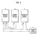
- the casting processcan be organized in a number of ways, by using an over-and-under conveyor holding a number of molds, or in a modular fashion, but preferably by utilizing 3 stations and a robot to manipulate the mold from preheat (A) to casting (B), and back to heating (A), then to cooling (C) and stripping as shown in the appended drawings.
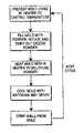
- FIG. 1is a flow chart describing the process steps of the present invention.
- FIG. 2is an exemplary schematic drawing of a process sequence in accordance with the present invention.
- FIG. 3is a sectional view of the contoured heating apparatus of the present invention.
- FIG. 4is a sectional view of the contoured cooling apparatus of the present invention.
- FIG. 1is a flow chart depicting the process steps used in the invention to produce plastic skins for automotive trim applications.
- a thin electroformed nickel moldis preheated using electric infrared heaters and when the mold reaches the preferred powder casting temperature for the specific plastic powder being processed, the mold is filled with powder, by using a powder box which clamps onto the mold face and when inverted fills the mold cavity with powder.
- the moldis then rotated generally around its major axis to allow the powder to contact the exposed heated inner surface of the electroformed mold and melt on this heated mold surface.
- the mold/powder box combinationis inverted and any unmelted powder falls back into the powder box which is then unclamped and retracted.
- thermoplastic formulationssuch as plastisols or organisols can be processed in a like manner.
- FIG. 2depicts this process in greater detail. While shown here as basic apparatus stations, it can take the form of a moving or indexing line, a robot manipulator and multiple stations as disclosed in 4,759,333 to Gray (and incorporated herein by reference), or any other sequence that is consistent with FIGS. 1 and 2 , including casting multiple layers of plastic, multiple types of plastic and foamed layers of thermoplastic to form skins or shells.
- an electroformed nickel moldis formed having the surface pattern (grain, texture, decoration) and contour desired for the final automotive skin or shell.
- this electroformis of a relatively uniform thickness between 0.100′′-0.150′′ to minimize the weight of nickel to be heated and cooled and to minimize internal stresses on the mold.
- Thinner moldsare possible depending on their shape and on their ability to support their own weight and that of the powder which must fill the mold to adequately coat the surface area to make a complete and uniform skin.
- Electric IR heatersare preferred as the energy, source as they are not noisy, do not emit gaseous pollution and are portable, allowing the heating elements to be contoured to match up to each specific mold shape.
- the tubular heaterswere provided with cold ends which simplified mounting and fiber washers sealed each end of the sleeve to allow moisture to vent.
- the tubular heaterswere bent in a pattern to conform to the backside of the electroformed mold about 1-3 inches off the mold surface and about 1-3 inches apart running lengthwise along the mold to uniformly cover the area of the mold to be heated.
- a thermocouplewas installed on the front surface of the mold at a point of average mold thickness to sense the temperature and control the tubular heater elements. To correct any problem with “cross-fire” (the problem of one heater element facing another and driving the opposite heater beyond its setpoint), each heater element was independently controlled using a solid state relay coupled with a voltage regulator.
- thermocoupleBy connecting a thermocouple to each heater element, if one heater starts to override the adjacent heat element, the thermocouple alerts the solid state controller which is programmed to reduce the voltage to that heater, preventing burnout.
- a heater arraywas provided which yields a uniform and consistent temperature, is specific to each mold shape and is portable such that it can easily be exchanged when a new mold shape is used.
- a most desirable heating sourceis provided without moving parts and without potential pollution issues of noise, heat and fumes.
- the use of black body absorptivitywas employed.
- Black paint capable of withstanding the temperatures encounteredwas applied to the backside of the tool to aid in heat transfer.
- Nickelhas an emissivity of 0.11 while a glossy black paint surface has an emissivity of 0.86. Since the plastic skin or shell being formed should be as uniform as possible, usually around 0.025-0.040 inches in thickness, in order to use as little powder as possible to cast each shell, heat balancing of the mold is necessary.
- thermography techniquesfirst to adjust the shape of the heater elements and distance from the mold back surface and finally, by sectioning and measuring the cast skins or shells for thickness every inch or so in both x and y dimensions. It was found that a fine tuning heat balance can be accomplished through the application of different shades of gray scale paint to the mold back surface. Particularly in areas of the mold which are thin (due to the complex geometry being electroformed) and in “waste” areas where little or no skin or shell is desired, such as might get trimmed out of openings in the final product or peripheral edges, light colored shades of grey paint may be applied to reduce the heat absorbed (and therefore the thickness of shell formed due to less melting of the powder). Further, more uniform mold temperatures result in more uniform gloss and color readings for the final cast skin or shell.
- FIG. 3is a sectional view of the heating apparatus of the present invention.
- An electroformed nickel mold 10is placed under an IR heating apparatus 20 .
- IR heating elements 14preferably run in a parallel array along the length of the mold and are contoured to follow the molds surface spaced off by a few inches and provide uniform heat.
- the preferred heating apparatusfurther comprises an outer frame 12 for support, a reflection shield 16 for containing the energy and directing it towards the mold surface and a layer of K-wool insulation 18 . This provides a lightweight heating apparatus which is easy to change out when a different mold shape is desired to be used.
- evaporative coolingis preferably employed. This eliminates the previous problems encountered using ambient air, especially during seasonal extremes (summer heat).
- the hot electroform mold containing the cast shellis sprayed using 100 psi air which atomizes cool water forced through spray nozzles (such as Binks or DeVilbis).
- spray nozzlessuch as Binks or DeVilbis.
- FIG. 4the spray nozzles are arranged in an adjustable pattern approximating the mold shape to ensure uniformity of cooling.
- An air over water cooling system using an air surge tank to maintain a constant high volume, high pressure supplywas provided.
- FIG. 4is a sectional view of the evaporative cooling apparatus.
- a frame 22is constructed to follow the shape of the mold and allow for rows of nozzles 24 to be installed along its length.
- the nozzles 24are preferably set to be evenly spaced apart and a consistent distance from the mold 10 , including its ends, to allow for even and rapid cooling. By spraying a fine mist of air and water, the water will be evaporated and little puddling will result.
- a robotthus manipulates the mold from heating station (A) (see FIG. 2 ), to casting station (B), back to heating station (A), and finally to cooling station (C). Having the spray nozzle for cooling in a separate station from heating allows for longer nozzle life without clogging.
- FIG. 2the process sequence will be described.
- An electroformed nickel moldis placed under an IR heating unit in station A, described in FIG. 2 at position 1 , in an inverted fashion where the backside of the mold has been painted black to optimize absorptivity.
- the IR heater elementswhich have been contoured to resemble the backside of the electroformed mold face the backside of the mold (see FIG. 3 ).
- a thermocoupleis attached to the mold cavity surface.
- the moldreaches the optimum casting temperature for the specific thermoplastic being cast (thermoplastic urethane, polyvinyl chloride, thermoplastic elastomer, thermoplastic olefin and the like)
- the moldis moved to a casting station B, as shown in FIG.
- the mold box/mold combinationis rotated around its major axis, powder contacting the hot mold surface melts to form a uniform plastic layer.
- the mold boxis separated with the mold, inverted so that any excess powder falls into the mold box and retracted.
- the electroformed moldnext moves back to the IR heating station A, shown at position 3 in FIG. 2 , to complete the fusing process (generally a mold temperature of around 400 degrees F.). After a brief 10 seconds or so, the mold moves to a cooling station C, shown in FIG.
- any process using latent heatis acceptable so that in addition to water, materials like liquid nitrogen, dry ice, (CO 2 ), etc. can find use.
- the spray nozzle patterncan be optimized by contouring the nozzle layout to resemble the mold contour.
- the inventionprovides a new and improved method for producing thin plastic skins or shells from a liquid or powder casting process.
- electric infrared heatingBy employing electric infrared heating, a simplified process requiring few molds, and much less ducting and conveying apparatus, and which emits significantly less noise and waste heat to the environment is achieved.
- a heat balancing method to provide uniform mold temperature, more uniform shell thickness and gloss uniformityis disclosed using black body absorptivity.
- latent heat of vaporization or sublimationis disclosed to provide significantly faster mold cooling cycles which contribute to faster total cycle times, reducing the number of molds and mold stations required to produce high volumes of shells.
Landscapes
- Engineering & Computer Science (AREA)
- Mechanical Engineering (AREA)
- Physics & Mathematics (AREA)
- Thermal Sciences (AREA)
- Manufacturing & Machinery (AREA)
- Moulding By Coating Moulds (AREA)
- Moulds For Moulding Plastics Or The Like (AREA)
- Extrusion Moulding Of Plastics Or The Like (AREA)
- Casting Or Compression Moulding Of Plastics Or The Like (AREA)
- Laminated Bodies (AREA)
Abstract
Description
Claims (11)
Priority Applications (2)
| Application Number | Priority Date | Filing Date | Title |
|---|---|---|---|
| US10/433,361US7425294B2 (en) | 2001-10-09 | 2002-10-09 | Plastic skin forming process |
| US10/641,997US7550103B2 (en) | 2001-10-09 | 2003-08-15 | Plastic skin forming process |
Applications Claiming Priority (4)
| Application Number | Priority Date | Filing Date | Title |
|---|---|---|---|
| US32797901P | 2001-10-09 | 2001-10-09 | |
| US60327979 | 2001-10-09 | ||
| US10/433,361US7425294B2 (en) | 2001-10-09 | 2002-10-09 | Plastic skin forming process |
| PCT/US2002/032413WO2003031139A1 (en) | 2001-10-09 | 2002-10-09 | Plastic skin forming process |
Publications (2)
| Publication Number | Publication Date |
|---|---|
| US20040065981A1 US20040065981A1 (en) | 2004-04-08 |
| US7425294B2true US7425294B2 (en) | 2008-09-16 |
Family
ID=23278949
Family Applications (1)
| Application Number | Title | Priority Date | Filing Date |
|---|---|---|---|
| US10/433,361Expired - LifetimeUS7425294B2 (en) | 2001-10-09 | 2002-10-09 | Plastic skin forming process |
Country Status (10)
| Country | Link |
|---|---|
| US (1) | US7425294B2 (en) |
| EP (1) | EP1436131B1 (en) |
| JP (1) | JP4613259B2 (en) |
| KR (1) | KR100909909B1 (en) |
| AT (1) | ATE403532T1 (en) |
| CA (1) | CA2431054C (en) |
| DE (1) | DE60228106D1 (en) |
| ES (1) | ES2311625T3 (en) |
| MX (1) | MXPA03005062A (en) |
| WO (1) | WO2003031139A1 (en) |
Cited By (2)
| Publication number | Priority date | Publication date | Assignee | Title |
|---|---|---|---|---|
| US11975462B2 (en) | 2017-02-16 | 2024-05-07 | Billio Pty Ltd | Cooling system for moulds |
| US12144964B2 (en) | 2009-07-30 | 2024-11-19 | Tandem Diabetes Care, Inc | Infusion pump system with disposable cartridge having pressure venting and pressure feedback |
Families Citing this family (7)
| Publication number | Priority date | Publication date | Assignee | Title |
|---|---|---|---|---|
| US7550103B2 (en) | 2001-10-09 | 2009-06-23 | International Automotive Components Group North America, Inc. | Plastic skin forming process |
| JP2007534513A (en)* | 2003-07-11 | 2007-11-29 | コリンズ・アンド・アイクマン・プロダクツ・コーポレーション | Cloth texture cover material |
| US20060091575A1 (en)* | 2004-11-03 | 2006-05-04 | Lear Corporation | Method and system for making interior vehicle trim panel having sprayed skin |
| US7287902B2 (en)* | 2005-06-07 | 2007-10-30 | The Boeing Company | Systems and methods for thermographic inspection of composite structures |
| US8220991B2 (en)* | 2006-05-12 | 2012-07-17 | The Boeing Company | Electromagnetically heating a conductive medium in a composite aircraft component |
| DE102008026365B4 (en) | 2008-06-02 | 2010-11-18 | International Automotive Components Group Gmbh | Apparatus and method for producing slush hides |
| EP3284569B1 (en)* | 2015-07-29 | 2020-05-20 | Nakata Coating Co., Ltd. | Powder slush molding machine and powder slush molding method |
Citations (49)
| Publication number | Priority date | Publication date | Assignee | Title |
|---|---|---|---|---|
| GB918065A (en) | 1960-11-29 | 1963-02-13 | Basf Ag | Insecticides |
| US3315016A (en) | 1964-06-25 | 1967-04-18 | Davidson Rubber Company Inc | Induction heated-slush molding process |
| US3346723A (en) | 1964-04-20 | 1967-10-10 | Heraeus Schott Quarzschmelze | Electric infrared emitter |
| US3419455A (en) | 1965-05-14 | 1968-12-31 | Arthur H. Roberts | Molded decorative article |
| US3449546A (en) | 1966-06-23 | 1969-06-10 | Xerox Corp | Infra-red heater |
| US3488411A (en) | 1966-04-20 | 1970-01-06 | Alumacraft Marine Products Cor | Production of low density thin gauge plastic articles |
| US3507950A (en) | 1967-04-24 | 1970-04-21 | Vistron Corp | Method of thermofusion molding |
| US3564656A (en) | 1968-01-24 | 1971-02-23 | Vistron Corp | Thermodynamic molding of plastic articles |
| US3677670A (en) | 1969-08-13 | 1972-07-18 | Sekisui Chemical Co Ltd | Rotational molding apparatus |
| US3728429A (en) | 1968-08-29 | 1973-04-17 | Mccord Corp | Slush molding process |
| USRE28497E (en) | 1959-10-15 | 1975-07-29 | Method of and apparatus for making a plastic article | |
| US3971674A (en) | 1975-03-03 | 1976-07-27 | Aluminum Company Of America | Selective black coating for aluminum |
| US4217325A (en) | 1977-04-21 | 1980-08-12 | Mccord Corporation | Method using modular slush molding machine |
| US4298324A (en) | 1977-09-09 | 1981-11-03 | Isobox-Barbier | Apparatus for molding particulate expandable thermoplastic resin material using microwave heating |
| US4389177A (en) | 1979-07-12 | 1983-06-21 | Mccord Corporation | Modular slush molding machine |
| US4583932A (en) | 1984-04-06 | 1986-04-22 | Societe A Responsabilite Limitee Datome | Rotational moulding machine |
| US4623503A (en) | 1984-11-21 | 1986-11-18 | Ex-Cell-O Corporation | Slush molding method with selective heating of mold by air jets |
| US4740337A (en) | 1986-05-27 | 1988-04-26 | Sheller-Globe Corporation | Powder slush process for making plastic articles |
| US4755333A (en) | 1985-07-01 | 1988-07-05 | Ex-Cell-O Corporation | Mold method and apparatus for plastic shells |
| US4759333A (en) | 1986-04-22 | 1988-07-26 | Mitsubishi Denki Kabushiki Kaisha | Fuel control apparatus |
| JPS63183819A (en) | 1987-01-26 | 1988-07-29 | Nissan Shatai Co Ltd | Method for molding skin material |
| EP0334074A2 (en) | 1988-03-23 | 1989-09-27 | Krauss-Maffei Aktiengesellschaft | Method and apparatus for producing formed plastic sheets |
| US4898697A (en) | 1988-12-23 | 1990-02-06 | Davidson Textron Inc. | Rotational slush molding method |
| EP0366407A2 (en) | 1988-10-24 | 1990-05-02 | Toray Engineering Co., Ltd. | Method of making a composite foamed and shaped article |
| US4929293A (en) | 1984-07-09 | 1990-05-29 | Fluoroware, Inc. | Welding fluoropolymer pipe and fittings |
| US4946638A (en) | 1987-03-26 | 1990-08-07 | Toyota Jidosha Kabushiki Kaisha | Slush molding method and apparatus therefor |
| US4946663A (en) | 1987-10-15 | 1990-08-07 | The British Petroleum Company, P.L.C. | Production of high surface area carbon fibres |
| US4979888A (en)* | 1988-03-23 | 1990-12-25 | Krauss-Maffei Aktiengesellschaft | Apparatus for molding an article from a fusible synthetic resin |
| US5002476A (en) | 1989-11-24 | 1991-03-26 | Lockheed Corporation | Tooling for composite parts |
| US5032076A (en) | 1990-07-12 | 1991-07-16 | Davidson Textron Inc. | Metal mold with extended heat transfer surface |
| US5059446A (en) | 1990-02-14 | 1991-10-22 | Armco Inc. | Method of producing plastic coated metal strip |
| US5106285A (en) | 1991-04-01 | 1992-04-21 | Davidson Textron Inc. | Air and water delivery system for a shell mold |
| US5308700A (en) | 1990-10-03 | 1994-05-03 | Sumitomo Chemical Company Limited | Thermoplastic elastomer powder for powder molding, powder molding method using the same and molded article thereof |
| JPH06190846A (en) | 1992-12-25 | 1994-07-12 | Nishikawa Kasei Co Ltd | Slush molding die and heater therefor |
| US5439406A (en) | 1992-10-09 | 1995-08-08 | Sony Corporation | Method for peeling the safety panel of a CRT |
| US5441675A (en) | 1993-11-01 | 1995-08-15 | Davidson Textron, Inc. | Forming method and apparatus |
| US5466412A (en) | 1992-09-28 | 1995-11-14 | Davidson Textron Inc. | Method for forming an outer skin for a cover assembly |
| US5580501A (en) | 1994-11-07 | 1996-12-03 | Gallagher; Michael J. | Method of manufacturing an interior trim panel using polyurethane powder |
| JPH10103623A (en)* | 1996-09-25 | 1998-04-21 | Noritake Co Ltd | Gas far infrared heater and far infrared heating furnace having tubular radiator |
| US5840229A (en) | 1994-11-16 | 1998-11-24 | Sumitomo Chemical Company, Limited | Method for producing molded article by powder slush molding a thermoplastic elastomer powder |
| EP0887378A1 (en)* | 1996-03-15 | 1998-12-30 | Sumitomo Chemical Company Limited | Thermoplastic elastomer composition and powder and molded article thereof |
| US5993721A (en) | 1995-04-05 | 1999-11-30 | Jsr Corporation | Molding process utilizing a molding apparatus |
| US6013210A (en) | 1997-04-18 | 2000-01-11 | Magna Interior Systems Inc. | Process for making decorative automotive interior trim articles with cast integral light stable covering |
| US6019390A (en) | 1998-04-30 | 2000-02-01 | Milliken & Company | Multiple panel airbag |
| US6019590A (en) | 1997-06-02 | 2000-02-01 | Konal Engineering And Equipment Inc. | Slush molding apparatus |
| US6071456A (en) | 1994-07-28 | 2000-06-06 | Dai Nippon Printing Co., Ltd. | Process for effecting injection-molded-in decoration |
| US6082989A (en) | 1998-11-13 | 2000-07-04 | Mcnally; Douglas J. | Slush molding apparatus |
| US6241929B1 (en) | 1999-07-29 | 2001-06-05 | Razmik L. Akopyan | Method and apparatus for molding three-dimensional objects of complex shape by means of RF heating |
| US6299817B1 (en) | 1990-10-16 | 2001-10-09 | Kevin G. Parkinson | Method for seamless construction of molded elastomer products |
Family Cites Families (1)
| Publication number | Priority date | Publication date | Assignee | Title |
|---|---|---|---|---|
| US5981611A (en)* | 1997-11-24 | 1999-11-09 | Prince Corporation | Thermoformable foam with infrared receptors |
- 2002
- 2002-10-09KRKR1020037007691Apatent/KR100909909B1/ennot_activeExpired - Fee Related
- 2002-10-09USUS10/433,361patent/US7425294B2/ennot_activeExpired - Lifetime
- 2002-10-09DEDE60228106Tpatent/DE60228106D1/ennot_activeExpired - Lifetime
- 2002-10-09JPJP2003534153Apatent/JP4613259B2/ennot_activeExpired - Fee Related
- 2002-10-09WOPCT/US2002/032413patent/WO2003031139A1/enactiveApplication Filing
- 2002-10-09EPEP02769039Apatent/EP1436131B1/ennot_activeExpired - Lifetime
- 2002-10-09ESES02769039Tpatent/ES2311625T3/ennot_activeExpired - Lifetime
- 2002-10-09MXMXPA03005062Apatent/MXPA03005062A/enactiveIP Right Grant
- 2002-10-09ATAT02769039Tpatent/ATE403532T1/ennot_activeIP Right Cessation
- 2002-10-09CACA2431054Apatent/CA2431054C/ennot_activeExpired - Lifetime
Patent Citations (50)
| Publication number | Priority date | Publication date | Assignee | Title |
|---|---|---|---|---|
| USRE28497E (en) | 1959-10-15 | 1975-07-29 | Method of and apparatus for making a plastic article | |
| GB918065A (en) | 1960-11-29 | 1963-02-13 | Basf Ag | Insecticides |
| US3346723A (en) | 1964-04-20 | 1967-10-10 | Heraeus Schott Quarzschmelze | Electric infrared emitter |
| US3315016A (en) | 1964-06-25 | 1967-04-18 | Davidson Rubber Company Inc | Induction heated-slush molding process |
| US3419455A (en) | 1965-05-14 | 1968-12-31 | Arthur H. Roberts | Molded decorative article |
| US3488411A (en) | 1966-04-20 | 1970-01-06 | Alumacraft Marine Products Cor | Production of low density thin gauge plastic articles |
| US3449546A (en) | 1966-06-23 | 1969-06-10 | Xerox Corp | Infra-red heater |
| US3507950A (en) | 1967-04-24 | 1970-04-21 | Vistron Corp | Method of thermofusion molding |
| US3564656A (en) | 1968-01-24 | 1971-02-23 | Vistron Corp | Thermodynamic molding of plastic articles |
| US3728429A (en) | 1968-08-29 | 1973-04-17 | Mccord Corp | Slush molding process |
| US3677670A (en) | 1969-08-13 | 1972-07-18 | Sekisui Chemical Co Ltd | Rotational molding apparatus |
| US3971674A (en) | 1975-03-03 | 1976-07-27 | Aluminum Company Of America | Selective black coating for aluminum |
| US4217325A (en) | 1977-04-21 | 1980-08-12 | Mccord Corporation | Method using modular slush molding machine |
| US4298324A (en) | 1977-09-09 | 1981-11-03 | Isobox-Barbier | Apparatus for molding particulate expandable thermoplastic resin material using microwave heating |
| US4389177A (en) | 1979-07-12 | 1983-06-21 | Mccord Corporation | Modular slush molding machine |
| US4583932A (en) | 1984-04-06 | 1986-04-22 | Societe A Responsabilite Limitee Datome | Rotational moulding machine |
| US4929293A (en) | 1984-07-09 | 1990-05-29 | Fluoroware, Inc. | Welding fluoropolymer pipe and fittings |
| US4623503A (en) | 1984-11-21 | 1986-11-18 | Ex-Cell-O Corporation | Slush molding method with selective heating of mold by air jets |
| US4755333A (en) | 1985-07-01 | 1988-07-05 | Ex-Cell-O Corporation | Mold method and apparatus for plastic shells |
| US4759333A (en) | 1986-04-22 | 1988-07-26 | Mitsubishi Denki Kabushiki Kaisha | Fuel control apparatus |
| US4740337A (en) | 1986-05-27 | 1988-04-26 | Sheller-Globe Corporation | Powder slush process for making plastic articles |
| JPS63183819A (en) | 1987-01-26 | 1988-07-29 | Nissan Shatai Co Ltd | Method for molding skin material |
| US4946638A (en) | 1987-03-26 | 1990-08-07 | Toyota Jidosha Kabushiki Kaisha | Slush molding method and apparatus therefor |
| US4946663A (en) | 1987-10-15 | 1990-08-07 | The British Petroleum Company, P.L.C. | Production of high surface area carbon fibres |
| EP0334074A2 (en) | 1988-03-23 | 1989-09-27 | Krauss-Maffei Aktiengesellschaft | Method and apparatus for producing formed plastic sheets |
| JPH01275108A (en) | 1988-03-23 | 1989-11-02 | Krauss Maffei Ag | Manufacture and production unit for plastic molded sheet |
| US4979888A (en)* | 1988-03-23 | 1990-12-25 | Krauss-Maffei Aktiengesellschaft | Apparatus for molding an article from a fusible synthetic resin |
| EP0366407A2 (en) | 1988-10-24 | 1990-05-02 | Toray Engineering Co., Ltd. | Method of making a composite foamed and shaped article |
| US4898697A (en) | 1988-12-23 | 1990-02-06 | Davidson Textron Inc. | Rotational slush molding method |
| US5002476A (en) | 1989-11-24 | 1991-03-26 | Lockheed Corporation | Tooling for composite parts |
| US5059446A (en) | 1990-02-14 | 1991-10-22 | Armco Inc. | Method of producing plastic coated metal strip |
| US5032076A (en) | 1990-07-12 | 1991-07-16 | Davidson Textron Inc. | Metal mold with extended heat transfer surface |
| US5308700A (en) | 1990-10-03 | 1994-05-03 | Sumitomo Chemical Company Limited | Thermoplastic elastomer powder for powder molding, powder molding method using the same and molded article thereof |
| US6299817B1 (en) | 1990-10-16 | 2001-10-09 | Kevin G. Parkinson | Method for seamless construction of molded elastomer products |
| US5106285A (en) | 1991-04-01 | 1992-04-21 | Davidson Textron Inc. | Air and water delivery system for a shell mold |
| US5466412A (en) | 1992-09-28 | 1995-11-14 | Davidson Textron Inc. | Method for forming an outer skin for a cover assembly |
| US5439406A (en) | 1992-10-09 | 1995-08-08 | Sony Corporation | Method for peeling the safety panel of a CRT |
| JPH06190846A (en) | 1992-12-25 | 1994-07-12 | Nishikawa Kasei Co Ltd | Slush molding die and heater therefor |
| US5441675A (en) | 1993-11-01 | 1995-08-15 | Davidson Textron, Inc. | Forming method and apparatus |
| US6071456A (en) | 1994-07-28 | 2000-06-06 | Dai Nippon Printing Co., Ltd. | Process for effecting injection-molded-in decoration |
| US5580501A (en) | 1994-11-07 | 1996-12-03 | Gallagher; Michael J. | Method of manufacturing an interior trim panel using polyurethane powder |
| US5840229A (en) | 1994-11-16 | 1998-11-24 | Sumitomo Chemical Company, Limited | Method for producing molded article by powder slush molding a thermoplastic elastomer powder |
| US5993721A (en) | 1995-04-05 | 1999-11-30 | Jsr Corporation | Molding process utilizing a molding apparatus |
| EP0887378A1 (en)* | 1996-03-15 | 1998-12-30 | Sumitomo Chemical Company Limited | Thermoplastic elastomer composition and powder and molded article thereof |
| JPH10103623A (en)* | 1996-09-25 | 1998-04-21 | Noritake Co Ltd | Gas far infrared heater and far infrared heating furnace having tubular radiator |
| US6013210A (en) | 1997-04-18 | 2000-01-11 | Magna Interior Systems Inc. | Process for making decorative automotive interior trim articles with cast integral light stable covering |
| US6019590A (en) | 1997-06-02 | 2000-02-01 | Konal Engineering And Equipment Inc. | Slush molding apparatus |
| US6019390A (en) | 1998-04-30 | 2000-02-01 | Milliken & Company | Multiple panel airbag |
| US6082989A (en) | 1998-11-13 | 2000-07-04 | Mcnally; Douglas J. | Slush molding apparatus |
| US6241929B1 (en) | 1999-07-29 | 2001-06-05 | Razmik L. Akopyan | Method and apparatus for molding three-dimensional objects of complex shape by means of RF heating |
Non-Patent Citations (3)
| Title |
|---|
| Harris, Daniel C., Materials For Infrared Windows and Domes, 1999, SPIE Optical Engineering Press, pp. 1-6 (Cited in the corresponding CIP U.S. Appl. No. 10/641,997 by the US Examiner). |
| International Search Report dated Mar. 3, 2005 issued in the corresponding International Appln. No. PCT/US04/26724 filed Aug. 16, 2004 (3 pgs). |
| Supplementary European Search Report dated Jun. 6, 2006 issued in the counterpart European Patent Application No. 02769039.5 filed Jul. 23, 2003 (3 pgs). |
Cited By (2)
| Publication number | Priority date | Publication date | Assignee | Title |
|---|---|---|---|---|
| US12144964B2 (en) | 2009-07-30 | 2024-11-19 | Tandem Diabetes Care, Inc | Infusion pump system with disposable cartridge having pressure venting and pressure feedback |
| US11975462B2 (en) | 2017-02-16 | 2024-05-07 | Billio Pty Ltd | Cooling system for moulds |
Also Published As
| Publication number | Publication date |
|---|---|
| ES2311625T3 (en) | 2009-02-16 |
| EP1436131A4 (en) | 2006-07-05 |
| ATE403532T1 (en) | 2008-08-15 |
| CA2431054A1 (en) | 2003-04-17 |
| KR100909909B1 (en) | 2009-07-29 |
| WO2003031139A1 (en) | 2003-04-17 |
| US20040065981A1 (en) | 2004-04-08 |
| EP1436131A1 (en) | 2004-07-14 |
| EP1436131B1 (en) | 2008-08-06 |
| JP2005505440A (en) | 2005-02-24 |
| MXPA03005062A (en) | 2004-09-10 |
| JP4613259B2 (en) | 2011-01-12 |
| KR20040041089A (en) | 2004-05-13 |
| CA2431054C (en) | 2010-12-14 |
| DE60228106D1 (en) | 2008-09-18 |
Similar Documents
| Publication | Publication Date | Title |
|---|---|---|
| US7550103B2 (en) | Plastic skin forming process | |
| EP0186285B1 (en) | Gas conditioned modular slush molding machine | |
| US7425294B2 (en) | Plastic skin forming process | |
| US5106285A (en) | Air and water delivery system for a shell mold | |
| JPH0564822A (en) | Apparatus and method for manufacturing plastic molded article | |
| US4979888A (en) | Apparatus for molding an article from a fusible synthetic resin | |
| US5370831A (en) | Method of molding polymeric skins for trim products | |
| US4755333A (en) | Mold method and apparatus for plastic shells | |
| GB1603337A (en) | Modular slush moulding machine | |
| IE913817A1 (en) | Improved method and apparatus for shaping thermoplastic tubes | |
| KR101947541B1 (en) | Powder Slush Molding Machine and Powder Slush Molding Method | |
| US4890995A (en) | Mold apparatus for forming shaped plastic shells | |
| US3564656A (en) | Thermodynamic molding of plastic articles | |
| MXPA06001768A (en) | ||
| US20070022624A1 (en) | Paint-drying system and method | |
| JP6644893B2 (en) | Powder slush molding machine and powder slush molding method | |
| JPH0481926B2 (en) | ||
| JPH01275108A (en) | Manufacture and production unit for plastic molded sheet | |
| JP6034544B1 (en) | Powder slush molding machine and powder slush molding method | |
| JPH061385Y2 (en) | Skin material forming equipment | |
| JPH0548730B2 (en) | ||
| JPH04135312U (en) | Molding equipment |
Legal Events
| Date | Code | Title | Description |
|---|---|---|---|
| AS | Assignment | Owner name:COLLINS & AIKMAN AUTOMOTIVE COMPANY INC., MICHIGAN Free format text:ASSIGNMENT OF ASSIGNORS INTEREST;ASSIGNORS:GRIMMER, ROBERT A.;SYPHERS, DAVE;MOORE, DENIS;REEL/FRAME:014704/0808;SIGNING DATES FROM 20031104 TO 20031117 | |
| AS | Assignment | Owner name:COLLINS & AIKMAN CORPORATION, MICHIGAN Free format text:CORRECTIVE ASSIGNMENT TO CORRECT THE NAME OF THE ASSIGNEE FROM COLLINS & AIKMAN AUTOMOTIVE COMPANY, INC. TO COLLINS & AIKMAN CORPORATION PREVIOUSLY RECORDED ON REEL 014992 FRAME 0255;ASSIGNORS:GRIMMER, ROBERT A.;MOORE, DENIS;REEL/FRAME:020032/0183 Effective date:20071029 | |
| AS | Assignment | Owner name:COLLINS & AIKMAN CORPORATION, MICHIGAN Free format text:CORRECTIVE ASSIGNMENT TO CORRECT THE NAME OF THE ASSIGNEE FROM COLLINS & AIKMAN AUTOMOTIVE COMPANY, INC. TO COLLINS & AIKMAN CORPORATION PREVIOUSLY RECORDED ON REEL 014992 FRAME 0255;ASSIGNOR:SYPHERS, DAVE;REEL/FRAME:020039/0242 Effective date:20071029 | |
| STCF | Information on status: patent grant | Free format text:PATENTED CASE | |
| AS | Assignment | Owner name:INTERNATIONAL AUTOMOTIVE COMPONENTS GROUP NORTH AM Free format text:ASSIGNMENT OF ASSIGNORS INTEREST;ASSIGNOR:COLLINS & AIKMAN CORPORATION;REEL/FRAME:021839/0133 Effective date:20071106 | |
| CC | Certificate of correction | ||
| AS | Assignment | Owner name:GENERAL ELECTRIC CAPITAL CORPORATION, AS AGENT, CO Free format text:SECURITY INTEREST;ASSIGNOR:INTERNATIONAL AUTOMOTIVE COMPONENTS GROUP NORTH AMERICA, INC;REEL/FRAME:025845/0193 Effective date:20101110 Owner name:GENERAL ELECTRIC CAPITAL CORPORATION, AS AGENT, CO Free format text:SECURITY AGREEMENT;ASSIGNOR:INTERNATIONAL AUTOMOTIVE COMPONENTS GROUP NORTH AMERICA, INC.;REEL/FRAME:025882/0019 Effective date:20101110 | |
| XAS | Not any more in us assignment database | Free format text:SECURITY INTEREST;ASSIGNOR:INTERNATIONAL AUTOMOTIVE COMPONENTS GROUP NORTH AMERICA, INC;REEL/FRAME:025845/0193 | |
| AS | Assignment | Owner name:THE BANK OF NEW YORK MELLON, AS COLLATERAL AGENT, Free format text:SECURITY AGREEMENT;ASSIGNOR:INTERNATIONAL AUTOMOTIVE COMPONENTS GROUP NORTH AMERICA, INC., A DELAWARE CORPORATION;REEL/FRAME:026404/0069 Effective date:20110603 | |
| FPAY | Fee payment | Year of fee payment:4 | |
| AS | Assignment | Owner name:CF LENDING, LLC , AS ADMINISTRATIVE AGENT, CONNECT Free format text:SECURITY INTEREST;ASSIGNOR:INTERNATIONAL AUTOMOTIVE COMPONENTS GROUP NORTH AMERICA, INC., AS GRANTOR;REEL/FRAME:036722/0294 Effective date:20150930 Owner name:CF LENDING, LLC , AS ADMINISTRATIVE AGENT, CONNECT Free format text:SECURITY INTEREST;ASSIGNOR:INTERNATIONAL AUTOMOTIVE COMPONENTS GROUP NORTH AMERICA, INC., AS GRANTOR;REEL/FRAME:036722/0440 Effective date:20150930 | |
| AS | Assignment | Owner name:THE BANK OF NEW YORK MELLON, AS COLLATERAL AGENT, Free format text:SECURITY AGREEMENT;ASSIGNOR:INTERNATIONAL AUTOMOTIVE COMPONENTS GROUP NORTH AMERICA, INC.;REEL/FRAME:036742/0576 Effective date:20150930 | |
| AS | Assignment | Owner name:INTERNATIONAL AUTOMOTIVE COMPONENTS GROUP NORTH AM Free format text:RELEASE BY SECURED PARTY;ASSIGNOR:THE BANK OF NEW YORK MELLON;REEL/FRAME:036777/0821 Effective date:20150930 Owner name:INTERNATIONAL AUTOMOTIVE COMPONENTS GROUP NORTH AM Free format text:RELEASE BY SECURED PARTY;ASSIGNOR:GENERAL ELECTRIC CAPITAL CORPORATION, AS COLLATERAL AGENT;REEL/FRAME:036777/0904 Effective date:20150930 | |
| FPAY | Fee payment | Year of fee payment:8 | |
| AS | Assignment | Owner name:CORTLAND CAPITAL MARKET SERVICES LLC, ILLINOIS Free format text:SECURITY INTEREST;ASSIGNOR:INTERNATIONAL AUTOMOTIVE COMPONENTS GROUP NORTH AMERICA, INC.;REEL/FRAME:045998/0550 Effective date:20180423 | |
| AS | Assignment | Owner name:INTERNATIONAL AUTOMOTIVE COMPONENTS GROUP NORTH AM Free format text:RELEASE OF SECURITY INTEREST IN PATENTS AT REEL 036742/FRAME 0576;ASSIGNOR:THE BANK OF NEW YORK MELLON, AS COLLATERAL AGENT;REEL/FRAME:046022/0599 Effective date:20180423 | |
| AS | Assignment | Owner name:WELLS FARGO BANK, N.A., AS ADMINISTRATIVE AGENT, M Free format text:PATENT SECURITY AGREEMENT (CANADIAN OBLIGATIONS);ASSIGNOR:INTERNATIONAL AUTOMOTIVE COMPONENTS GROUP NORTH AMERICA, INC.;REEL/FRAME:046674/0610 Effective date:20180724 | |
| MAFP | Maintenance fee payment | Free format text:PAYMENT OF MAINTENANCE FEE, 12TH YEAR, LARGE ENTITY (ORIGINAL EVENT CODE: M1553); ENTITY STATUS OF PATENT OWNER: LARGE ENTITY Year of fee payment:12 | |
| AS | Assignment | Owner name:CORTLAND CAPITAL MARKET SERVICES LLC, ILLINOIS Free format text:SECURITY INTEREST;ASSIGNOR:INTERNATIONAL AUTOMOTIVE COMPONENTS GROUP NORTH AMERICA, INC.;REEL/FRAME:052923/0888 Effective date:20200611 | |
| AS | Assignment | Owner name:BLUE TORCH FINANCE LLC, AS ADMINISTRATIVE AGENT, NEW YORK Free format text:PATENT SECURITY AGREEMENT;ASSIGNOR:INTERNATIONAL AUTOMOTIVE COMPONENTS GROUP NORTH AMERICA, INC.;REEL/FRAME:057569/0893 Effective date:20210922 | |
| AS | Assignment | Owner name:INTERNATIONAL AUTOMOTIVE COMPONENTS GROUP NORTH AMERICA, INC., MICHIGAN Free format text:TERMINATION AND RELEASE OF INTELLECTUAL PROPERTY SECURITY AGREEMENTS;ASSIGNOR:WELLS FARGO BANK, N.A.;REEL/FRAME:067853/0742 Effective date:20240620 | |
| AS | Assignment | Owner name:INTERNATIONAL AUTOMOTIVE COMPONENTS GROUP GMBH, GERMANY Free format text:RELEASE OF PATENT SECURITY AGREEMENT RECORDED AT REEL/FRAME 067006/0846;ASSIGNOR:BLUE TORCH FINANCE LLC;REEL/FRAME:071494/0946 Effective date:20250530 Owner name:INTERNATIONAL AUTOMOTIVE COMPONENTS GROUP NORTH AMERICA, INC., MICHIGAN Free format text:RELEASE OF PATENT SECURITY AGREEMENT RECORDED AT REEL/FRAME 067006/0846;ASSIGNOR:BLUE TORCH FINANCE LLC;REEL/FRAME:071494/0946 Effective date:20250530 Owner name:INTERNATIONAL AUTOMOTIVE COMPONENTS GROUP GMBH, GERMANY Free format text:RELEASE OF PATENT SECURITY AGREEMENT RECORDED AT REEL/FRAME 063121/0799;ASSIGNOR:BLUE TORCH FINANCE LLC;REEL/FRAME:071494/0928 Effective date:20250530 Owner name:INTERNATIONAL AUTOMOTIVE COMPONENTS GROUP NORTH AMERICA, INC., MICHIGAN Free format text:RELEASE OF PATENT SECURITY AGREEMENT RECORDED AT REEL/FRAME 063121/0799;ASSIGNOR:BLUE TORCH FINANCE LLC;REEL/FRAME:071494/0928 Effective date:20250530 Owner name:INTERNATIONAL AUTOMOTIVE COMPONENTS GROUP GMBH, GERMANY Free format text:RELEASE OF PATENT SECURITY AGREEMENT RECORDED AT REEL/FRAME 057569/0893;ASSIGNOR:BLUE TORCH FINANCE LLC;REEL/FRAME:071494/0829 Effective date:20250530 Owner name:INTERNATIONAL AUTOMOTIVE COMPONENTS GROUP NORTH AMERICA, INC., MICHIGAN Free format text:RELEASE OF PATENT SECURITY AGREEMENT RECORDED AT REEL/FRAME 057569/0893;ASSIGNOR:BLUE TORCH FINANCE LLC;REEL/FRAME:071494/0829 Effective date:20250530 |