US7425232B2 - Hydrogen storage apparatus comprised of halloysite - Google Patents
Hydrogen storage apparatus comprised of halloysiteDownload PDFInfo
- Publication number
- US7425232B2 US7425232B2US11/099,055US9905505AUS7425232B2US 7425232 B2US7425232 B2US 7425232B2US 9905505 AUS9905505 AUS 9905505AUS 7425232 B2US7425232 B2US 7425232B2
- Authority
- US
- United States
- Prior art keywords
- halloysite
- rods
- hydrogen
- recited
- substrate
- Prior art date
- Legal status (The legal status is an assumption and is not a legal conclusion. Google has not performed a legal analysis and makes no representation as to the accuracy of the status listed.)
- Expired - Fee Related, expires
Links
Images


Classifications
- F—MECHANICAL ENGINEERING; LIGHTING; HEATING; WEAPONS; BLASTING
- F17—STORING OR DISTRIBUTING GASES OR LIQUIDS
- F17C—VESSELS FOR CONTAINING OR STORING COMPRESSED, LIQUEFIED OR SOLIDIFIED GASES; FIXED-CAPACITY GAS-HOLDERS; FILLING VESSELS WITH, OR DISCHARGING FROM VESSELS, COMPRESSED, LIQUEFIED, OR SOLIDIFIED GASES
- F17C11/00—Use of gas-solvents or gas-sorbents in vessels
- F17C11/005—Use of gas-solvents or gas-sorbents in vessels for hydrogen
- B—PERFORMING OPERATIONS; TRANSPORTING
- B01—PHYSICAL OR CHEMICAL PROCESSES OR APPARATUS IN GENERAL
- B01D—SEPARATION
- B01D61/00—Processes of separation using semi-permeable membranes, e.g. dialysis, osmosis or ultrafiltration; Apparatus, accessories or auxiliary operations specially adapted therefor
- B01D61/14—Ultrafiltration; Microfiltration
- B01D61/20—Accessories; Auxiliary operations
- B—PERFORMING OPERATIONS; TRANSPORTING
- B82—NANOTECHNOLOGY
- B82Y—SPECIFIC USES OR APPLICATIONS OF NANOSTRUCTURES; MEASUREMENT OR ANALYSIS OF NANOSTRUCTURES; MANUFACTURE OR TREATMENT OF NANOSTRUCTURES
- B82Y30/00—Nanotechnology for materials or surface science, e.g. nanocomposites
- H—ELECTRICITY
- H01—ELECTRIC ELEMENTS
- H01M—PROCESSES OR MEANS, e.g. BATTERIES, FOR THE DIRECT CONVERSION OF CHEMICAL ENERGY INTO ELECTRICAL ENERGY
- H01M8/00—Fuel cells; Manufacture thereof
- H01M8/04—Auxiliary arrangements, e.g. for control of pressure or for circulation of fluids
- H01M8/04082—Arrangements for control of reactant parameters, e.g. pressure or concentration
- H01M8/04201—Reactant storage and supply, e.g. means for feeding, pipes
- H01M8/04208—Cartridges, cryogenic media or cryogenic reservoirs
- H—ELECTRICITY
- H01—ELECTRIC ELEMENTS
- H01M—PROCESSES OR MEANS, e.g. BATTERIES, FOR THE DIRECT CONVERSION OF CHEMICAL ENERGY INTO ELECTRICAL ENERGY
- H01M8/00—Fuel cells; Manufacture thereof
- H01M8/04—Auxiliary arrangements, e.g. for control of pressure or for circulation of fluids
- H01M8/04082—Arrangements for control of reactant parameters, e.g. pressure or concentration
- H01M8/04201—Reactant storage and supply, e.g. means for feeding, pipes
- H01M8/04216—Reactant storage and supply, e.g. means for feeding, pipes characterised by the choice for a specific material, e.g. carbon, hydride, absorbent
- Y—GENERAL TAGGING OF NEW TECHNOLOGICAL DEVELOPMENTS; GENERAL TAGGING OF CROSS-SECTIONAL TECHNOLOGIES SPANNING OVER SEVERAL SECTIONS OF THE IPC; TECHNICAL SUBJECTS COVERED BY FORMER USPC CROSS-REFERENCE ART COLLECTIONS [XRACs] AND DIGESTS
- Y02—TECHNOLOGIES OR APPLICATIONS FOR MITIGATION OR ADAPTATION AGAINST CLIMATE CHANGE
- Y02E—REDUCTION OF GREENHOUSE GAS [GHG] EMISSIONS, RELATED TO ENERGY GENERATION, TRANSMISSION OR DISTRIBUTION
- Y02E60/00—Enabling technologies; Technologies with a potential or indirect contribution to GHG emissions mitigation
- Y02E60/30—Hydrogen technology
- Y02E60/32—Hydrogen storage
- Y—GENERAL TAGGING OF NEW TECHNOLOGICAL DEVELOPMENTS; GENERAL TAGGING OF CROSS-SECTIONAL TECHNOLOGIES SPANNING OVER SEVERAL SECTIONS OF THE IPC; TECHNICAL SUBJECTS COVERED BY FORMER USPC CROSS-REFERENCE ART COLLECTIONS [XRACs] AND DIGESTS
- Y02—TECHNOLOGIES OR APPLICATIONS FOR MITIGATION OR ADAPTATION AGAINST CLIMATE CHANGE
- Y02E—REDUCTION OF GREENHOUSE GAS [GHG] EMISSIONS, RELATED TO ENERGY GENERATION, TRANSMISSION OR DISTRIBUTION
- Y02E60/00—Enabling technologies; Technologies with a potential or indirect contribution to GHG emissions mitigation
- Y02E60/30—Hydrogen technology
- Y02E60/50—Fuel cells
- Y—GENERAL TAGGING OF NEW TECHNOLOGICAL DEVELOPMENTS; GENERAL TAGGING OF CROSS-SECTIONAL TECHNOLOGIES SPANNING OVER SEVERAL SECTIONS OF THE IPC; TECHNICAL SUBJECTS COVERED BY FORMER USPC CROSS-REFERENCE ART COLLECTIONS [XRACs] AND DIGESTS
- Y10—TECHNICAL SUBJECTS COVERED BY FORMER USPC
- Y10S—TECHNICAL SUBJECTS COVERED BY FORMER USPC CROSS-REFERENCE ART COLLECTIONS [XRACs] AND DIGESTS
- Y10S502/00—Catalyst, solid sorbent, or support therefor: product or process of making
- Y10S502/526—Sorbent for fluid storage, other than an alloy for hydrogen storage
Definitions
- the present inventiongenerally relates to an apparatus for storing molecular hydrogen. More particularly, the present invention relates to a hydrogen storage device comprised of halloysite rods.
- Carbon nanofibersincluding single-walled carbon nanotubes (SWNTs), multiwall nanotubes (MWNTs), and graphite nanofibers (GNF), have shown promise for applications in hydrogen storage due to the electronic nature resulting of sp 2 hybridization, large surface areas, and molecular sized pores.”
- SWNTssingle-walled carbon nanotubes
- MWNTsmultiwall nanotubes
- GNFgraphite nanofibers
- an apparatus for storing hydrogenwhich is comprised of molecular hydrogen, halloysite rods, and a supporting substrate wherein hydrogen is stored within the lumen of the halloysite rods.
- FIG. 1is a Scanning Electron Microscopy (SEM) image of a sample of halloysite
- FIG. 2Ais a perspective view of a single halloysite rod while FIG. 2B is an end view of the same rod;
- FIG. 3is a schematic illustration of a multiplicity of halloysite rods disposed on a substrate
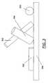
- FIG. 4is a perspective view of a substrate with halloysite rods disposed on the substrate;
- FIGS. 5A , 5 B and 5 Care perspective views of three tubular substrates with halloysite rods disposed thereon;
- FIG. 6is a schematic view of a substrate with halloysite rods disposed within a sealed storage container
- FIG. 7is a schematic view of a plurality of substrates with halloysite rods disposed within a sealed storage container
- FIG. 8is a flow diagram of one process of the invention.
- FIG. 9is an illustration of the X-ray Diffraction patterns of two samples of naturally occurring halloysites.
- Halloysite nanotubesdon't clump together, making them ideal for use in electronic fabrication and other high-tech ceramic-composite applications.”
- the applicantshave discovered non-carbon nanotubes comprised of halloysite rods that are particularly well adapted to the storage of molecular hydrogen.
- FIG. 1is a Scanning Electron Microscopy (SEM) image of a sample of halloysite 100 .
- SEMScanning Electron Microscopy
- halloysitemay exist in a variety of morphologies, including spherical agglomerates and tubular rods.
- the present inventionutilizes the tubular halloysite rods as a hydrogen storage device.
- halloysite 100is comprised of halloysite rod 102 and halloysite agglomerate 104 .
- FIG. 2Ais a perspective view of a single halloysite rod 200 and FIG. 2B is an end view of halloysite rod 200 .
- Halloysite rod 200is comprised of lumen 202 .
- molecular hydrogenmay be disposed in lumen 202 .
- halloysite rod 200may function as a hydrogen storage apparatus in a manner similar to the hydrogen storage capability of carbon nanotubes.
- the length 204 of halloysite rods such as 200vary from about 100 nm to about 1 ⁇ m or more.
- TEMTransmission Electron Microscopy
- TEMTransmission Electron Microscopy
- the inside diameter 208 of halloysite rodsranges from about 0.02 to about 0.04 microns and outside diameter 206 varies from about 0.04 to about 0.08 microns.
- the term “aspect ratio”refers to the ratio of the length 204 to the outside diameter 206 .
- halloysite rodsare selected which have an aspect ratio of from about 1 to about 10.
- halloysite rodsare selected which have an aspect ratio of from about 2 to about 8.
- halloysite rodsare selected which have an aspect ratio of from about 3 to about 10.
- FIG. 2also illustrates another property of halloysite rods: their surface to volume ratio.
- the hollow lumen of the rodsprovides a high surface to volume ratio.
- the halloysite rodshave a surface to volume ratio of about 1 to about 10,000.
- the halloysite rodshave a surface to volume ratio of about 10 to about 1,000.
- the outer diameter 206 of halloysite rodsis about 50 nm
- the inner diameter 208is about 20 nm
- the lengthmay vary from about 200 to about 500 nm. In other embodiments, the length of the rod may be as long as several micrometers.
- FIG. 3is a schematic illustration of a multiplicity of halloysite rods 300 , 302 and 304 disposed on a substrate 306 .
- rods 300 , 302 and 304have different aspect ratios.
- at least about 80 weight percent of the halloysite rodshave substantially the same aspect ratio.
- the aspect ratiovaries such that at least about 80 weight percent of the halloysite rods have an aspect ratio from about 3 to about 10.
- at least about 80 weight percent of the halloysite rodshave an aspect ratio from about 5 to about 8.
- halloysite agglomerate 308is also disposed on the surface of substrate 306 .
- the halloysite sampleis comprised of at least about 30 weight percent halloysite rods and the remainder of the halloysite consists essentially of halloysite agglomerates.
- the halloysite sampleis comprised of at least about 50 weight percent halloysite rods.
- the halloysite sampleis comprised of at least about 60 weight percent halloysite rods.
- FIG. 4is a perspective view of a substrate with halloysite rods disposed thereon.
- substrate 306is coated with halloysite rods 400 , 402 , 406 and 408 .
- halloysite rods 400 to 408need not be parallel to one another, nor do they need to be parallel to the surface of substrate 306 .
- halloysite rod 408is not parallel to the surface of substrate 306 .
- halloysite agglomerate 308is also disposed on the surface of substrate 306 .
- substrate 306is flexible, and can be folded into a tube or cylinder.
- FIGS. 5A , 5 B and 5 Cillustrate three embodiments wherein substrate 306 is sufficiently flexible to be folded into a tube or cylinder.
- the outer surface of flexible substrate 306has been coated with halloysite rods 500 .
- the inner surface of flexible substrate 306has been coated with halloysite rods 500 .
- both the inner and outer surface of flexible substrate 306has been coated with halloysite rods 500 .
- FIG. 6is a schematic view of one hydrogen storage apparatus of the present invention.
- the hydrogen storage apparatus 600is comprised of flexible substrate 306 which, in the embodiment depicted, has halloysite rods 500 disposed on the surface thereof.
- Flexible substrate 306has been folded into a tubular or cylindrical shape.
- Substrate 306 and halloysite rods 500are disposed within sealed storage container 602 .
- Storage container 602is sealed such that it is substantially air-tight.
- the air-tight seal of storage container 602may be broken by operating valves 604 and 606 . In the embodiment depicted two such valves are illustrated. In another embodiment, only one such valve is used.
- FIG. 7is a schematic view of another hydrogen storage apparatus of the present invention.
- the hydrogen storage apparatus 700is similar to apparatus 600 depicted in FIG. 6 except in that a plurality of substrates 306 are employed.
- FIG. 8is a flow diagram of one process 800 of the invention.
- halloysite rodsare obtained. Not all samples of halloysite are identical.
- FIG. 9illustrates the XRD (X-ray Diffraction) patterns of two samples of naturally occurring halloysite samples: Halloysite AZ Mill (from Halloysite S.E. Wall AZ Mill (AZ sample)) and CA Mill (from Halloysite N.W. PitWall Canada Mill (CA sample)).
- Halloysite AZ Millfrom Halloysite S.E. Wall AZ Mill (AZ sample)
- CA Millfrom Halloysite N.W. PitWall Canada Mill
- the AZ samplescontained more halloysite than the CA samples, as illustrated by the sharper and more intense peaks seen in FIG. 9 .
- the AZ halloysite samplecontained less than about 10 volume percent rods.
- the CA halloysite samplecontained fewer rods than the AZ sample.
- step 802is comprised of the step of using electrostatic techniques to select halloysite rods.
- centrifugal techniquesare used.
- a simple filtering techniqueis used wherein the small agglomerates are removed, thus increasing the percentage of rods.
- the halloysite rodsare obtained by synthesizing the rods.
- the density difference between halloysite rods and halloysite agglomeratesis exploited, and the halloysite is disposed in an appropriate liquid with the desirable density.
- electrostatic techniquesare used to select the halloysite rods.
- Yuri M. Lvoventitled “Nanofabrication of ordered multilayers by alternate adsorption of polyions, nanoparticles and proteins: From planer films to microtemplates.” [online], [retrieved on Mar. 27, 2005].
- a positively charged substrateis brought into the proximity of a crude halloysite sample. The negatively charged particles of halloysite are attracted to the positively charged substrate.
- centrifugal techniquesare used to select the halloysite rods.
- centrifugationis a well known technique that separates particles and solutions based on a variety of factors, including particle density, density of the supporting media, particle shape, and particle mass.
- a wide variety of centrifugation techniqueshave been developed to separate particulates.
- continuous flow centrifugationis used to separate large quantities of halloysite rods from crude halloysite. Reference may be had to U.S. Pat. No. 5,641,622 to Lake (Continuous Centrifugation Process for the Separation of Biological Components from Heterogeneous Cell Populations); U.S. Pat. Nos.
- rodsare selected by first placing the crude halloysite within a media of a selected density.
- Those halloysite particles with a density substantially similar to the density of the mediawill be buoyant and are thus easily isolated from the particles wherein the density is not substantially similar.
- Similar technologyis well known to those skilled in the art. Reference may be had to U.S. Pat. No. 4,547,286 to Hsiung (Water Filtration Process and Apparatus Having Upflow Filter with Buoyant Filter Media and Downflow Filter with Nonbuoyant Filter Media), the content of which is hereby incorporated by reference into this specification.
- similar buoyancy based separationmay be combined with centrifugation techniques. Such techniques are often referred to as equilibrium centrifugation or gradient centrifugation and utilize CsCl as the media.
- halloysite rods of a specified morphologyfor example, a certain aspect ratio.
- halloysite rodsare selected which have an aspect ratio of from about 1 to about 10.
- halloysite rodsare selected which have an aspect ratio of from about 2 to about 8.
- halloysite rodsare selected which have an aspect ratio of from about 3 to about 10. Additional information related to the isolation of halloysite rods can be found in applicant's patent application U.S. Ser. No. 11/042,219, filed on Jan. 25, 2005, the content of which is hereby incorporated by reference into this specification.
- this substratemay be a flexible substrate.
- the flexible substrateis stainless steel.
- the substrateis a flexible polymeric substrate.
- the flexible polymeric substrateis a polyanionic substrate.
- the next stepis the immersion of the polycation covered substrate into a dilute dispersion of polyanion or negatively charged nanoparticles (or any other nanosized charged species) also for a time optimized for the adsorption of a monolayer, then rinsed and dried.
- These operationscomplete the self-assembly of a polyelectrolyte monolayer and monoparticulate layer sandwich unit onto the substrate . . . .
- Subsequent sandwich unitsare self-assembled analogously.”
- the same paperalso discloses that “At pH above 4 halloysite is negatively charged” and may thus serve as a “nanosized charged species.”
- a variety of polycationsmay be used to facilitate the binding of anionic halloysite to the substrate.
- Lvovprovided a variety of substrates with halloysite attached.
- Lvovprovided both monolayered halloysite (thickness of approximately 54 ⁇ 5 nm) and multilayered (thickness of approximately 720 nm) halloysite.
- the resulting polyanion filmswere “ . . . insoluble in water and in many organic solvents and are stable to at least 200° C.”
- a sealed storage containeris formed about the substrate(s) in step 806 .
- the sealed storage containeris formed about a single coated substrate (see FIG. 6 ).
- the sealed storage containeris formed about a plurality of coated substrates (see FIG. 7 ).
- the sealed storage containeris formed prior to step 804 .
- step 808hydrogen is stored within the lumen of the halloysite rods.
- This storagemay be effected by conventional means such as, e.g., the processes used to store hydrogen in carbon nanotube assemblies.
- Referencemay be had, e.g., to U.S. Pat. No. 6,159,538 to Rodriguez (Method For Introducing Hydrogen Into Layered Nanostructures); U.S. Pat. No. 6,672,077 to Bradley (Hydrogen Storage In Nanostructure With Physisorption); U.S. Pat. No. 6,596,055 to Cooper (Hydrogen Storage Using Carbon-Metal Hybrid Compositions); U.S. Pat. No.
Landscapes
- Engineering & Computer Science (AREA)
- Chemical & Material Sciences (AREA)
- Chemical Kinetics & Catalysis (AREA)
- Nanotechnology (AREA)
- Water Supply & Treatment (AREA)
- Life Sciences & Earth Sciences (AREA)
- Manufacturing & Machinery (AREA)
- Sustainable Development (AREA)
- Sustainable Energy (AREA)
- Electrochemistry (AREA)
- General Chemical & Material Sciences (AREA)
- Physics & Mathematics (AREA)
- Condensed Matter Physics & Semiconductors (AREA)
- General Physics & Mathematics (AREA)
- Materials Engineering (AREA)
- Crystallography & Structural Chemistry (AREA)
- Composite Materials (AREA)
- Mechanical Engineering (AREA)
- General Engineering & Computer Science (AREA)
- Solid-Sorbent Or Filter-Aiding Compositions (AREA)
Abstract
Description
Claims (20)
Priority Applications (2)
| Application Number | Priority Date | Filing Date | Title |
|---|---|---|---|
| US11/099,055US7425232B2 (en) | 2004-04-05 | 2005-04-05 | Hydrogen storage apparatus comprised of halloysite |
| US11/151,073US7491263B2 (en) | 2004-04-05 | 2005-06-13 | Storage assembly |
Applications Claiming Priority (3)
| Application Number | Priority Date | Filing Date | Title |
|---|---|---|---|
| US55955504P | 2004-04-05 | 2004-04-05 | |
| US11/042,219US20060163160A1 (en) | 2005-01-25 | 2005-01-25 | Halloysite microtubule processes, structures, and compositions |
| US11/099,055US7425232B2 (en) | 2004-04-05 | 2005-04-05 | Hydrogen storage apparatus comprised of halloysite |
Related Parent Applications (1)
| Application Number | Title | Priority Date | Filing Date |
|---|---|---|---|
| US11/042,219Continuation-In-PartUS20060163160A1 (en) | 2004-04-05 | 2005-01-25 | Halloysite microtubule processes, structures, and compositions |
Related Child Applications (1)
| Application Number | Title | Priority Date | Filing Date |
|---|---|---|---|
| US11/151,073Continuation-In-PartUS7491263B2 (en) | 2004-04-05 | 2005-06-13 | Storage assembly |
Publications (2)
| Publication Number | Publication Date |
|---|---|
| US20050233199A1 US20050233199A1 (en) | 2005-10-20 |
| US7425232B2true US7425232B2 (en) | 2008-09-16 |
Family
ID=36695944
Family Applications (1)
| Application Number | Title | Priority Date | Filing Date |
|---|---|---|---|
| US11/099,055Expired - Fee RelatedUS7425232B2 (en) | 2004-04-05 | 2005-04-05 | Hydrogen storage apparatus comprised of halloysite |
Country Status (1)
| Country | Link |
|---|---|
| US (1) | US7425232B2 (en) |
Cited By (7)
| Publication number | Priority date | Publication date | Assignee | Title |
|---|---|---|---|---|
| US20080200601A1 (en)* | 2005-08-26 | 2008-08-21 | Cid Centro De Investigacion Y Desarrollo Tecnologico Sa De Cv | Reactive block copolymers for the preparation of inorganic tubule-polymer composites |
| US20090000192A1 (en)* | 2005-06-24 | 2009-01-01 | Washington State University Research Foundation | Apparatus with high surface area nanostructures for hydrogen storage, and methods of storing hydrogen |
| US20100215915A1 (en)* | 2005-06-24 | 2010-08-26 | Washington State University | Method for manufacture and coating of nanostructured components |
| US20110053020A1 (en)* | 2007-11-09 | 2011-03-03 | Washington State University Research Foundation | Catalysts and related methods |
| DE102011010525A1 (en) | 2011-02-08 | 2012-08-09 | Universität Rostock | Process for the purification of biogas, flue gas or liquids, adsorbent therefor, filters, and use of the adsorbent |
| KR101484174B1 (en)* | 2013-07-16 | 2015-01-28 | 광주과학기술원 | Composite comprising halloysite nanotube and conductive polymer |
| US9192912B1 (en) | 2011-04-13 | 2015-11-24 | Louisiana Tech University Research Foundation; a Division of Louisiana Tech University Foundation | Ceramic nanotube composites with sustained drug release capability for implants, bone repair and regeneration |
Citations (106)
| Publication number | Priority date | Publication date | Assignee | Title |
|---|---|---|---|---|
| US3581159A (en) | 1969-11-12 | 1971-05-25 | Union Carbide Corp | Solid electrolyte capacitor having improved counterelectrode system |
| US3648126A (en) | 1970-12-28 | 1972-03-07 | Standard Oil Co Ohio | Electrical capacitor employing paste electrodes |
| US3915731A (en) | 1972-01-28 | 1975-10-28 | Mizusawa Industrial Chem | Aqueous composition containing color former for pressure-sensitive production |
| US4019934A (en) | 1972-03-30 | 1977-04-26 | Taro Takayama | Inorganic gel-ammonium nitrate composite material and method of manufacturing the same |
| US4098676A (en) | 1974-11-19 | 1978-07-04 | Exxon Research & Engineering Co. | Synthetic halloysites as hydrocarbon conversion catalysts |
| US4364857A (en) | 1981-01-12 | 1982-12-21 | Chevron Research Company | Fibrous clay mixtures |
| US4383606A (en) | 1980-12-19 | 1983-05-17 | Johnson Matthey, Inc. | Hydrogen storage system |
| US4485387A (en) | 1982-10-26 | 1984-11-27 | Microscience Systems Corp. | Inking system for producing circuit patterns |
| US4547286A (en) | 1980-07-22 | 1985-10-15 | Neptune Microfloc, Inc. | Water filtration process and apparatus having upflow filter with buoyant filter media and downflow filter with nonbuoyant filter media |
| US4739007A (en) | 1985-09-30 | 1988-04-19 | Kabushiki Kaisha Toyota Chou Kenkyusho | Composite material and process for manufacturing same |
| US4741841A (en) | 1986-06-16 | 1988-05-03 | Industrial Filter & Pump Mfg. Co. | Method and apparatus for particle separation |
| US4790942A (en) | 1983-12-20 | 1988-12-13 | Membrex Incorporated | Filtration method and apparatus |
| US4810734A (en) | 1987-03-26 | 1989-03-07 | Kabushiki Kaisha Toyota Chuo Kenkyusho | Process for producing composite material |
| US4838606A (en) | 1986-09-01 | 1989-06-13 | Nissan Motor Co., Ltd. | Door guard bar |
| US4867917A (en) | 1986-12-24 | 1989-09-19 | Schnur Joel M | Method for synthesis of diacetylenic compounds |
| US4877501A (en) | 1987-02-06 | 1989-10-31 | Schnur Joel M | Process for fabrication of lipid microstructures |
| US4894411A (en) | 1987-03-18 | 1990-01-16 | Kabushiki Kaisha Toyota Chuo Kenkyusho | Composite material and process for producing the same |
| US4911981A (en) | 1987-06-16 | 1990-03-27 | Schnur Joel M | Metal clad lipid microstructures |
| US4944883A (en) | 1987-01-13 | 1990-07-31 | Schoendorfer Donald W | Continuous centrifugation system and method for directly deriving intermediate density material from a suspension |
| US4960450A (en) | 1989-09-19 | 1990-10-02 | Syracuse University | Selection and preparation of activated carbon for fuel gas storage |
| US4990291A (en) | 1986-04-15 | 1991-02-05 | The United States Of America As Represented By The Secretary Of The Navy | Method of making lipid tubules by a cooling process |
| US5049382A (en) | 1989-04-14 | 1991-09-17 | The United States Of America As Represented By The Secretary Of The Navy | Coating and composition containing lipid microstructure toxin dispensers |
| US5053127A (en) | 1987-01-13 | 1991-10-01 | William F. McLaughlin | Continuous centrifugation system and method for directly deriving intermediate density material from a suspension |
| US5096551A (en) | 1990-08-31 | 1992-03-17 | The United States Of America As Represented By The Secretary Of The Navy | Metallized tubule-based artificial dielectric |
| US5102948A (en) | 1989-05-19 | 1992-04-07 | Ube Industries, Ltd. | Polyamide composite material and method for preparing the same |
| US5164440A (en) | 1988-07-20 | 1992-11-17 | Ube Industries, Ltd. | High rigidity and impact resistance resin composition |
| US5171206A (en) | 1990-03-12 | 1992-12-15 | Beckman Instruments, Inc. | Optimal centrifugal separation |
| US5246689A (en) | 1990-01-25 | 1993-09-21 | Mobil Oil Corporation | Synthetic porous crystalline material its synthesis and use |
| US5248720A (en) | 1988-09-06 | 1993-09-28 | Ube Industries, Ltd. | Process for preparing a polyamide composite material |
| US5492696A (en) | 1989-04-14 | 1996-02-20 | The Government Of The United States Of America As Represented By The Secretary Of The Navy | Controlled release microstructures |
| US5641622A (en) | 1990-09-13 | 1997-06-24 | Baxter International Inc. | Continuous centrifugation process for the separation of biological components from heterogeneous cell populations |
| US5651976A (en) | 1993-06-17 | 1997-07-29 | The United States Of America As Represented By The Secretary Of The Navy | Controlled release of active agents using inorganic tubules |
| US5653951A (en) | 1995-01-17 | 1997-08-05 | Catalytic Materials Limited | Storage of hydrogen in layered nanostructures |
| US5654117A (en) | 1992-08-19 | 1997-08-05 | Xerox Corporation | Process for preparing an electrophotographic imaging member |
| US5674173A (en) | 1995-04-18 | 1997-10-07 | Cobe Laboratories, Inc. | Apparatus for separating particles |
| US5681464A (en) | 1993-07-20 | 1997-10-28 | Alfa Laval Brewery Systems Ab | Filter for cross-flow filtration |
| US5705191A (en) | 1995-08-18 | 1998-01-06 | The United States Of America As Represented By The Secretary Of The Navy | Sustained delivery of active compounds from tubules, with rational control |
| US5722923A (en) | 1995-08-08 | 1998-03-03 | Lui; Herman | Device for abdominal muscle exercise |
| US5783085A (en) | 1982-12-13 | 1998-07-21 | Estate Of William F. Mclaughlin | Blood fractionation method |
| US5827186A (en) | 1997-04-11 | 1998-10-27 | Light Sciences Limited Partnership | Method and PDT probe for minimizing CT and MRI image artifacts |
| US5854326A (en) | 1995-08-29 | 1998-12-29 | Sumitomo Chemical Company, Limited | Gas barrier resin composition and process for producing the same |
| US5906792A (en) | 1996-01-19 | 1999-05-25 | Hydro-Quebec And Mcgill University | Nanocrystalline composite for hydrogen storage |
| US5906570A (en) | 1995-04-18 | 1999-05-25 | Cobe Laboratories, Inc. | Particle filter apparatus |
| US5939319A (en) | 1995-04-18 | 1999-08-17 | Cobe Laboratories, Inc. | Particle separation method and apparatus |
| US5972448A (en) | 1996-07-09 | 1999-10-26 | Tetra Laval Holdings & Finance, Sa | Nanocomposite polymer container |
| US5993996A (en) | 1997-09-16 | 1999-11-30 | Inorganic Specialists, Inc. | Carbon supercapacitor electrode materials |
| US6013206A (en) | 1998-05-18 | 2000-01-11 | The United States Of America As Represented By The Secretary Of The Navy | Process for the formation of high aspect ratio lipid microtubules |
| US6034163A (en) | 1997-12-22 | 2000-03-07 | Eastman Chemical Company | Polyester nanocomposites for high barrier applications |
| US6051146A (en) | 1998-01-20 | 2000-04-18 | Cobe Laboratories, Inc. | Methods for separation of particles |
| US6060549A (en) | 1997-05-20 | 2000-05-09 | Exxon Chemical Patents, Inc. | Rubber toughened thermoplastic resin nano composites |
| US6067480A (en) | 1997-04-02 | 2000-05-23 | Stratasys, Inc. | Method and apparatus for in-situ formation of three-dimensional solid objects by extrusion of polymeric materials |
| US6074453A (en) | 1996-10-30 | 2000-06-13 | Iowa State University Research Foundation, Inc. | Ultrafine hydrogen storage powders |
| US6117541A (en) | 1997-07-02 | 2000-09-12 | Tetra Laval Holdings & Finance, Sa | Polyolefin material integrated with nanophase particles |
| US6143052A (en) | 1997-07-03 | 2000-11-07 | Kiyokawa Plating Industries, Co., Ltd. | Hydrogen storage material |
| US6159538A (en) | 1999-06-15 | 2000-12-12 | Rodriguez; Nelly M. | Method for introducing hydrogen into layered nanostructures |
| US6190775B1 (en) | 2000-02-24 | 2001-02-20 | Siemens Westinghouse Power Corporation | Enhanced dielectric strength mica tapes |
| US6195443B1 (en) | 1998-05-15 | 2001-02-27 | Xerox Corporation | System using on-line liquid characterization apparatus |
| US6207793B1 (en) | 1997-01-17 | 2001-03-27 | Korea Ptg Co., Ltd. | Process for production of polytetramethylene-ether-glycol-diester using halloysite catalyst |
| US6231980B1 (en) | 1995-02-14 | 2001-05-15 | The Regents Of The University Of California | BX CY NZ nanotubes and nanoparticles |
| US6265038B1 (en) | 1996-07-09 | 2001-07-24 | Tetra Laval Holdings & Finance, Sa | Transparent high barrier multilayer structure |
| US6290753B1 (en) | 1998-02-06 | 2001-09-18 | Institutt For Energiteknikk | Hydrogen storage in carbon material |
| US6294142B1 (en) | 1999-06-18 | 2001-09-25 | General Motors Corporation | Hydrogen storage systems and method of making them |
| US6331253B1 (en) | 1997-04-15 | 2001-12-18 | Commissariat A L'energie Atomique | Method and plant for tangential filtration of a viscous liquid |
| US6354986B1 (en) | 2000-02-16 | 2002-03-12 | Gambro, Inc. | Reverse-flow chamber purging during centrifugal separation |
| US6356433B1 (en) | 2000-03-03 | 2002-03-12 | The Regents Of The University Of California | Conducting polymer ultracapacitor |
| US6401816B1 (en) | 1999-03-03 | 2002-06-11 | The United States Of America As Represented By The Secretary Of The Navy | Efficient method for subsurface treatments, including squeeze treatments |
| US20020110686A1 (en) | 2001-02-09 | 2002-08-15 | Dugan Jeffrey S. | Fibers including a nanocomposite material |
| US20020132875A1 (en) | 2000-12-29 | 2002-09-19 | Dental Technologies, Inc. | Solid nanocomposites and their use in dental applications |
| US6461513B1 (en) | 2000-05-19 | 2002-10-08 | Filtration Solutions, Inc. | Secondary-flow enhanced filtration system |
| US20020150529A1 (en) | 2002-04-03 | 2002-10-17 | Dillon Anne C. | Single-wall carbon nanotubes for hydrogen storage or superbundle formation |
| US20020161101A1 (en) | 2001-03-22 | 2002-10-31 | Clemson University | Halogen containing-polymer nanocomposite compositions, methods, and products employing such compositions |
| US6475071B1 (en) | 2000-08-25 | 2002-11-05 | Micron Technology, Inc. | Cross flow slurry filtration apparatus and method |
| US6491789B2 (en) | 1997-06-04 | 2002-12-10 | Hyperion Catalysis International, Inc. | Fibril composite electrode for electrochemical capacitors |
| US20020187896A1 (en) | 2001-04-30 | 2002-12-12 | Ryong Ryoo | Carbon molecular sieve and process for preparing the same |
| US6517800B1 (en) | 1999-06-16 | 2003-02-11 | Institute Of Metal Research Of The Chinese Academy Of Sciences | Production of single-walled carbon nanotubes by a hydrogen arc discharge method |
| US6578596B1 (en) | 2000-04-18 | 2003-06-17 | Stratasys, Inc. | Apparatus and method for thermoplastic extrusion |
| US6589312B1 (en) | 1999-09-01 | 2003-07-08 | David G. Snow | Nanoparticles for hydrogen storage, transportation, and distribution |
| US6591617B2 (en) | 2001-08-22 | 2003-07-15 | Lockheed Martin Corporation | Method and apparatus for hydrogen storage and retrieval |
| US6596055B2 (en) | 2000-11-22 | 2003-07-22 | Air Products And Chemicals, Inc. | Hydrogen storage using carbon-metal hybrid compositions |
| US20030191224A1 (en) | 2002-03-27 | 2003-10-09 | Tsukasa Maruyama | Organically modified layered clay as well as organic polymer composition and tire inner liner containing same |
| US20030203989A1 (en) | 2002-03-15 | 2003-10-30 | Eastman Kodak Company | Article utilizing highly branched polymers to splay layered materials |
| US6665169B2 (en) | 1996-05-15 | 2003-12-16 | Hyperion Catalysis International, Inc. | Graphitic nanofibers in electrochemical capacitors |
| US6667354B1 (en) | 2000-07-18 | 2003-12-23 | Phillips Petroleum Company | Stable liquid suspension compositions and suspending mediums for same |
| US6672077B1 (en) | 2001-12-11 | 2004-01-06 | Nanomix, Inc. | Hydrogen storage in nanostructure with physisorption |
| US20040011668A1 (en) | 1999-12-16 | 2004-01-22 | Shiepe Jason K. | Electrochemical cell system and method of operation |
| US20040034122A1 (en) | 2002-08-16 | 2004-02-19 | Lacy William B. | Golf ball compositions comprising metallized lipid-based nanotubules |
| US6704192B2 (en) | 1999-02-19 | 2004-03-09 | Amtek Research International Llc | Electrically conductive, freestanding microporous sheet for use in an ultracapacitor |
| US6710111B2 (en) | 2000-10-26 | 2004-03-23 | Industrial Technology Research Institute | Polymer nanocomposites and the process of preparing the same |
| US20040059303A1 (en) | 2000-03-28 | 2004-03-25 | Bemis Manufacturing Company | Medical suction apparatus and methods for draining same |
| US20040068038A1 (en) | 2002-05-24 | 2004-04-08 | Robello Douglas R. | Exfoliated polystyrene-clay nanocomposite comprising star-shaped polymer |
| US20040067033A1 (en) | 2002-10-07 | 2004-04-08 | Eastman Kodak Company | Waveguide with nanoparticle induced refractive index gradient |
| US6728456B1 (en) | 2002-10-11 | 2004-04-27 | Eastman Kodak Company | Waveguide with nanoparticle induced refractive index gradient |
| US20040101466A1 (en) | 2000-01-19 | 2004-05-27 | Dillon Anne C | Metal-doped single-walled carbon nanotubes and production thereof |
| US6749414B1 (en) | 2001-04-30 | 2004-06-15 | Stratasys, Inc. | Extrusion apparatus for three-dimensional modeling |
| US6767952B2 (en) | 2001-11-13 | 2004-07-27 | Eastman Kodak Company | Article utilizing block copolymer intercalated clay |
| US6770697B2 (en) | 2001-02-20 | 2004-08-03 | Solvay Engineered Polymers | High melt-strength polyolefin composites and methods for making and using same |
| US20040173531A1 (en) | 2002-07-22 | 2004-09-09 | Hammond John M. | Fluid separation and delivery apparatus and method |
| US6790403B1 (en) | 1999-04-20 | 2004-09-14 | Stratasys, Inc. | Soluble material and process for three-dimensional modeling |
| US6797342B1 (en) | 2000-09-15 | 2004-09-28 | Xerox Corporation | Deflocculation apparatus and methods thereof |
| US6811599B2 (en) | 2000-03-13 | 2004-11-02 | Nederlandse Organisatie Voor Toegepast-Natuurwetenschappelijk Onderzoek Tno | Biodegradable thermoplastic material |
| US20040222561A1 (en) | 2003-05-05 | 2004-11-11 | Stratasys, Inc. | Material and method for three-dimensional modeling |
| US20040233526A1 (en) | 2003-05-22 | 2004-11-25 | Eastman Kodak Company | Optical element with nanoparticles |
| US20040242752A1 (en) | 2003-05-28 | 2004-12-02 | Nitto Denko Corporation | Hydrophilized porous film and process for producing the same |
| US6832037B2 (en) | 2002-08-09 | 2004-12-14 | Eastman Kodak Company | Waveguide and method of making same |
| US20040259999A1 (en) | 2003-06-20 | 2004-12-23 | Korea Institute Of Science And Technology | Polyester/clay nanocomposite and preparation method |
| US7248460B2 (en) | 2003-05-30 | 2007-07-24 | Sanyo Electric Co., Ltd. | Electric double layer capacitor and electrolytic cell |
Family Cites Families (1)
| Publication number | Priority date | Publication date | Assignee | Title |
|---|---|---|---|---|
| US4790945A (en)* | 1987-05-08 | 1988-12-13 | Shell Oil Company | Removal of hydrogen selenide |
- 2005
- 2005-04-05USUS11/099,055patent/US7425232B2/ennot_activeExpired - Fee Related
Patent Citations (111)
| Publication number | Priority date | Publication date | Assignee | Title |
|---|---|---|---|---|
| US3581159A (en) | 1969-11-12 | 1971-05-25 | Union Carbide Corp | Solid electrolyte capacitor having improved counterelectrode system |
| US3648126A (en) | 1970-12-28 | 1972-03-07 | Standard Oil Co Ohio | Electrical capacitor employing paste electrodes |
| US3915731A (en) | 1972-01-28 | 1975-10-28 | Mizusawa Industrial Chem | Aqueous composition containing color former for pressure-sensitive production |
| US4019934A (en) | 1972-03-30 | 1977-04-26 | Taro Takayama | Inorganic gel-ammonium nitrate composite material and method of manufacturing the same |
| US4098676A (en) | 1974-11-19 | 1978-07-04 | Exxon Research & Engineering Co. | Synthetic halloysites as hydrocarbon conversion catalysts |
| US4150099A (en) | 1974-11-19 | 1979-04-17 | Exxon Research & Engineering Co. | Synthetic halloysites |
| US4547286A (en) | 1980-07-22 | 1985-10-15 | Neptune Microfloc, Inc. | Water filtration process and apparatus having upflow filter with buoyant filter media and downflow filter with nonbuoyant filter media |
| US4383606A (en) | 1980-12-19 | 1983-05-17 | Johnson Matthey, Inc. | Hydrogen storage system |
| US4364857A (en) | 1981-01-12 | 1982-12-21 | Chevron Research Company | Fibrous clay mixtures |
| US4485387A (en) | 1982-10-26 | 1984-11-27 | Microscience Systems Corp. | Inking system for producing circuit patterns |
| US5783085A (en) | 1982-12-13 | 1998-07-21 | Estate Of William F. Mclaughlin | Blood fractionation method |
| US4790942A (en) | 1983-12-20 | 1988-12-13 | Membrex Incorporated | Filtration method and apparatus |
| US4739007A (en) | 1985-09-30 | 1988-04-19 | Kabushiki Kaisha Toyota Chou Kenkyusho | Composite material and process for manufacturing same |
| US4990291A (en) | 1986-04-15 | 1991-02-05 | The United States Of America As Represented By The Secretary Of The Navy | Method of making lipid tubules by a cooling process |
| US4741841A (en) | 1986-06-16 | 1988-05-03 | Industrial Filter & Pump Mfg. Co. | Method and apparatus for particle separation |
| US4838606A (en) | 1986-09-01 | 1989-06-13 | Nissan Motor Co., Ltd. | Door guard bar |
| US4867917A (en) | 1986-12-24 | 1989-09-19 | Schnur Joel M | Method for synthesis of diacetylenic compounds |
| US5053127A (en) | 1987-01-13 | 1991-10-01 | William F. McLaughlin | Continuous centrifugation system and method for directly deriving intermediate density material from a suspension |
| US4944883A (en) | 1987-01-13 | 1990-07-31 | Schoendorfer Donald W | Continuous centrifugation system and method for directly deriving intermediate density material from a suspension |
| US4877501A (en) | 1987-02-06 | 1989-10-31 | Schnur Joel M | Process for fabrication of lipid microstructures |
| US4894411A (en) | 1987-03-18 | 1990-01-16 | Kabushiki Kaisha Toyota Chuo Kenkyusho | Composite material and process for producing the same |
| US4810734A (en) | 1987-03-26 | 1989-03-07 | Kabushiki Kaisha Toyota Chuo Kenkyusho | Process for producing composite material |
| US4911981A (en) | 1987-06-16 | 1990-03-27 | Schnur Joel M | Metal clad lipid microstructures |
| US5164440A (en) | 1988-07-20 | 1992-11-17 | Ube Industries, Ltd. | High rigidity and impact resistance resin composition |
| US5248720A (en) | 1988-09-06 | 1993-09-28 | Ube Industries, Ltd. | Process for preparing a polyamide composite material |
| US5049382A (en) | 1989-04-14 | 1991-09-17 | The United States Of America As Represented By The Secretary Of The Navy | Coating and composition containing lipid microstructure toxin dispensers |
| US6280759B1 (en) | 1989-04-14 | 2001-08-28 | Ronald R. Price | Method of controlled release and controlled release microstructures |
| US5492696A (en) | 1989-04-14 | 1996-02-20 | The Government Of The United States Of America As Represented By The Secretary Of The Navy | Controlled release microstructures |
| US5102948A (en) | 1989-05-19 | 1992-04-07 | Ube Industries, Ltd. | Polyamide composite material and method for preparing the same |
| US4960450A (en) | 1989-09-19 | 1990-10-02 | Syracuse University | Selection and preparation of activated carbon for fuel gas storage |
| US5246689A (en) | 1990-01-25 | 1993-09-21 | Mobil Oil Corporation | Synthetic porous crystalline material its synthesis and use |
| US5171206A (en) | 1990-03-12 | 1992-12-15 | Beckman Instruments, Inc. | Optimal centrifugal separation |
| US5096551A (en) | 1990-08-31 | 1992-03-17 | The United States Of America As Represented By The Secretary Of The Navy | Metallized tubule-based artificial dielectric |
| US5641622A (en) | 1990-09-13 | 1997-06-24 | Baxter International Inc. | Continuous centrifugation process for the separation of biological components from heterogeneous cell populations |
| US5654117A (en) | 1992-08-19 | 1997-08-05 | Xerox Corporation | Process for preparing an electrophotographic imaging member |
| US5651976A (en) | 1993-06-17 | 1997-07-29 | The United States Of America As Represented By The Secretary Of The Navy | Controlled release of active agents using inorganic tubules |
| US5681464A (en) | 1993-07-20 | 1997-10-28 | Alfa Laval Brewery Systems Ab | Filter for cross-flow filtration |
| US5653951A (en) | 1995-01-17 | 1997-08-05 | Catalytic Materials Limited | Storage of hydrogen in layered nanostructures |
| US6231980B1 (en) | 1995-02-14 | 2001-05-15 | The Regents Of The University Of California | BX CY NZ nanotubes and nanoparticles |
| US6071422A (en) | 1995-04-18 | 2000-06-06 | Cobe Laboratories, Inc. | Particle separation method and apparatus |
| US5906570A (en) | 1995-04-18 | 1999-05-25 | Cobe Laboratories, Inc. | Particle filter apparatus |
| US5913768A (en) | 1995-04-18 | 1999-06-22 | Cobe Laboratories, Inc. | Particle filter apparatus |
| US5939319A (en) | 1995-04-18 | 1999-08-17 | Cobe Laboratories, Inc. | Particle separation method and apparatus |
| US5951877A (en) | 1995-04-18 | 1999-09-14 | Cobe Laboratories, Inc. | Particle filter method |
| US5674173A (en) | 1995-04-18 | 1997-10-07 | Cobe Laboratories, Inc. | Apparatus for separating particles |
| US5722923A (en) | 1995-08-08 | 1998-03-03 | Lui; Herman | Device for abdominal muscle exercise |
| US5705191A (en) | 1995-08-18 | 1998-01-06 | The United States Of America As Represented By The Secretary Of The Navy | Sustained delivery of active compounds from tubules, with rational control |
| US5854326A (en) | 1995-08-29 | 1998-12-29 | Sumitomo Chemical Company, Limited | Gas barrier resin composition and process for producing the same |
| US5906792A (en) | 1996-01-19 | 1999-05-25 | Hydro-Quebec And Mcgill University | Nanocrystalline composite for hydrogen storage |
| US6665169B2 (en) | 1996-05-15 | 2003-12-16 | Hyperion Catalysis International, Inc. | Graphitic nanofibers in electrochemical capacitors |
| US5972448A (en) | 1996-07-09 | 1999-10-26 | Tetra Laval Holdings & Finance, Sa | Nanocomposite polymer container |
| US6265038B1 (en) | 1996-07-09 | 2001-07-24 | Tetra Laval Holdings & Finance, Sa | Transparent high barrier multilayer structure |
| US6074453A (en) | 1996-10-30 | 2000-06-13 | Iowa State University Research Foundation, Inc. | Ultrafine hydrogen storage powders |
| US6207793B1 (en) | 1997-01-17 | 2001-03-27 | Korea Ptg Co., Ltd. | Process for production of polytetramethylene-ether-glycol-diester using halloysite catalyst |
| US6067480A (en) | 1997-04-02 | 2000-05-23 | Stratasys, Inc. | Method and apparatus for in-situ formation of three-dimensional solid objects by extrusion of polymeric materials |
| US5827186A (en) | 1997-04-11 | 1998-10-27 | Light Sciences Limited Partnership | Method and PDT probe for minimizing CT and MRI image artifacts |
| US6331253B1 (en) | 1997-04-15 | 2001-12-18 | Commissariat A L'energie Atomique | Method and plant for tangential filtration of a viscous liquid |
| US6060549A (en) | 1997-05-20 | 2000-05-09 | Exxon Chemical Patents, Inc. | Rubber toughened thermoplastic resin nano composites |
| US6491789B2 (en) | 1997-06-04 | 2002-12-10 | Hyperion Catalysis International, Inc. | Fibril composite electrode for electrochemical capacitors |
| US6117541A (en) | 1997-07-02 | 2000-09-12 | Tetra Laval Holdings & Finance, Sa | Polyolefin material integrated with nanophase particles |
| US6143052A (en) | 1997-07-03 | 2000-11-07 | Kiyokawa Plating Industries, Co., Ltd. | Hydrogen storage material |
| US5993996A (en) | 1997-09-16 | 1999-11-30 | Inorganic Specialists, Inc. | Carbon supercapacitor electrode materials |
| US6034163A (en) | 1997-12-22 | 2000-03-07 | Eastman Chemical Company | Polyester nanocomposites for high barrier applications |
| US6051146A (en) | 1998-01-20 | 2000-04-18 | Cobe Laboratories, Inc. | Methods for separation of particles |
| US6290753B1 (en) | 1998-02-06 | 2001-09-18 | Institutt For Energiteknikk | Hydrogen storage in carbon material |
| US6195443B1 (en) | 1998-05-15 | 2001-02-27 | Xerox Corporation | System using on-line liquid characterization apparatus |
| US6013206A (en) | 1998-05-18 | 2000-01-11 | The United States Of America As Represented By The Secretary Of The Navy | Process for the formation of high aspect ratio lipid microtubules |
| US6704192B2 (en) | 1999-02-19 | 2004-03-09 | Amtek Research International Llc | Electrically conductive, freestanding microporous sheet for use in an ultracapacitor |
| US6401816B1 (en) | 1999-03-03 | 2002-06-11 | The United States Of America As Represented By The Secretary Of The Navy | Efficient method for subsurface treatments, including squeeze treatments |
| US6790403B1 (en) | 1999-04-20 | 2004-09-14 | Stratasys, Inc. | Soluble material and process for three-dimensional modeling |
| US6159538A (en) | 1999-06-15 | 2000-12-12 | Rodriguez; Nelly M. | Method for introducing hydrogen into layered nanostructures |
| US6517800B1 (en) | 1999-06-16 | 2003-02-11 | Institute Of Metal Research Of The Chinese Academy Of Sciences | Production of single-walled carbon nanotubes by a hydrogen arc discharge method |
| US6294142B1 (en) | 1999-06-18 | 2001-09-25 | General Motors Corporation | Hydrogen storage systems and method of making them |
| US6589312B1 (en) | 1999-09-01 | 2003-07-08 | David G. Snow | Nanoparticles for hydrogen storage, transportation, and distribution |
| US20040011668A1 (en) | 1999-12-16 | 2004-01-22 | Shiepe Jason K. | Electrochemical cell system and method of operation |
| US20040101466A1 (en) | 2000-01-19 | 2004-05-27 | Dillon Anne C | Metal-doped single-walled carbon nanotubes and production thereof |
| US6354986B1 (en) | 2000-02-16 | 2002-03-12 | Gambro, Inc. | Reverse-flow chamber purging during centrifugal separation |
| US6190775B1 (en) | 2000-02-24 | 2001-02-20 | Siemens Westinghouse Power Corporation | Enhanced dielectric strength mica tapes |
| US6356433B1 (en) | 2000-03-03 | 2002-03-12 | The Regents Of The University Of California | Conducting polymer ultracapacitor |
| US6811599B2 (en) | 2000-03-13 | 2004-11-02 | Nederlandse Organisatie Voor Toegepast-Natuurwetenschappelijk Onderzoek Tno | Biodegradable thermoplastic material |
| US20040059303A1 (en) | 2000-03-28 | 2004-03-25 | Bemis Manufacturing Company | Medical suction apparatus and methods for draining same |
| US6578596B1 (en) | 2000-04-18 | 2003-06-17 | Stratasys, Inc. | Apparatus and method for thermoplastic extrusion |
| US6461513B1 (en) | 2000-05-19 | 2002-10-08 | Filtration Solutions, Inc. | Secondary-flow enhanced filtration system |
| US6667354B1 (en) | 2000-07-18 | 2003-12-23 | Phillips Petroleum Company | Stable liquid suspension compositions and suspending mediums for same |
| US6475071B1 (en) | 2000-08-25 | 2002-11-05 | Micron Technology, Inc. | Cross flow slurry filtration apparatus and method |
| US6797342B1 (en) | 2000-09-15 | 2004-09-28 | Xerox Corporation | Deflocculation apparatus and methods thereof |
| US6710111B2 (en) | 2000-10-26 | 2004-03-23 | Industrial Technology Research Institute | Polymer nanocomposites and the process of preparing the same |
| US6596055B2 (en) | 2000-11-22 | 2003-07-22 | Air Products And Chemicals, Inc. | Hydrogen storage using carbon-metal hybrid compositions |
| US20020132875A1 (en) | 2000-12-29 | 2002-09-19 | Dental Technologies, Inc. | Solid nanocomposites and their use in dental applications |
| US20020110686A1 (en) | 2001-02-09 | 2002-08-15 | Dugan Jeffrey S. | Fibers including a nanocomposite material |
| US6770697B2 (en) | 2001-02-20 | 2004-08-03 | Solvay Engineered Polymers | High melt-strength polyolefin composites and methods for making and using same |
| US20020161101A1 (en) | 2001-03-22 | 2002-10-31 | Clemson University | Halogen containing-polymer nanocomposite compositions, methods, and products employing such compositions |
| US20020187896A1 (en) | 2001-04-30 | 2002-12-12 | Ryong Ryoo | Carbon molecular sieve and process for preparing the same |
| US6749414B1 (en) | 2001-04-30 | 2004-06-15 | Stratasys, Inc. | Extrusion apparatus for three-dimensional modeling |
| US6591617B2 (en) | 2001-08-22 | 2003-07-15 | Lockheed Martin Corporation | Method and apparatus for hydrogen storage and retrieval |
| US6767952B2 (en) | 2001-11-13 | 2004-07-27 | Eastman Kodak Company | Article utilizing block copolymer intercalated clay |
| US6672077B1 (en) | 2001-12-11 | 2004-01-06 | Nanomix, Inc. | Hydrogen storage in nanostructure with physisorption |
| US20030203989A1 (en) | 2002-03-15 | 2003-10-30 | Eastman Kodak Company | Article utilizing highly branched polymers to splay layered materials |
| US20030191224A1 (en) | 2002-03-27 | 2003-10-09 | Tsukasa Maruyama | Organically modified layered clay as well as organic polymer composition and tire inner liner containing same |
| US20020150529A1 (en) | 2002-04-03 | 2002-10-17 | Dillon Anne C. | Single-wall carbon nanotubes for hydrogen storage or superbundle formation |
| US20040068038A1 (en) | 2002-05-24 | 2004-04-08 | Robello Douglas R. | Exfoliated polystyrene-clay nanocomposite comprising star-shaped polymer |
| US20040173531A1 (en) | 2002-07-22 | 2004-09-09 | Hammond John M. | Fluid separation and delivery apparatus and method |
| US6832037B2 (en) | 2002-08-09 | 2004-12-14 | Eastman Kodak Company | Waveguide and method of making same |
| US20040034122A1 (en) | 2002-08-16 | 2004-02-19 | Lacy William B. | Golf ball compositions comprising metallized lipid-based nanotubules |
| US20040067033A1 (en) | 2002-10-07 | 2004-04-08 | Eastman Kodak Company | Waveguide with nanoparticle induced refractive index gradient |
| US6728456B1 (en) | 2002-10-11 | 2004-04-27 | Eastman Kodak Company | Waveguide with nanoparticle induced refractive index gradient |
| US20040222561A1 (en) | 2003-05-05 | 2004-11-11 | Stratasys, Inc. | Material and method for three-dimensional modeling |
| US20040233526A1 (en) | 2003-05-22 | 2004-11-25 | Eastman Kodak Company | Optical element with nanoparticles |
| US20040242752A1 (en) | 2003-05-28 | 2004-12-02 | Nitto Denko Corporation | Hydrophilized porous film and process for producing the same |
| US7248460B2 (en) | 2003-05-30 | 2007-07-24 | Sanyo Electric Co., Ltd. | Electric double layer capacitor and electrolytic cell |
| US20040259999A1 (en) | 2003-06-20 | 2004-12-23 | Korea Institute Of Science And Technology | Polyester/clay nanocomposite and preparation method |
Non-Patent Citations (18)
| Title |
|---|
| An et al., "High-Capacitance Supercapacitor Using a Nanocomposite Electrode of Single-WalledCarbon Nanotube and Polypyrrole" Journal of the Electrochemical Society, 149(8) A1058-A-1062 (2002). |
| An et al.; Characterization of Supercapacitors Using Singlewalled Carbon Nanotube Electrodes; Journal of the Korean Physical Society, vol. 39 (Dec. 2001) pp. S511-S517. |
| Atlas Mining Company Enters into Collaborative Agreement with NaturalNano Inc., from Industrialnewsupdate.com, Mar. 30, 2005, http://www.industrialnewsupdate.com/news/metals-mining/archives/2005/01/atlas<SUB>-</SUB>mining<SUB>-</SUB>co.pho. |
| Atlas Mining Company Enters into Collaborative Agreement with NaturalNano Inc., from Industrialnewsupdate.com, Mar. 30, 2005, http://www.industrialnewsupdate.com/news/metals-mining/archives/2005/01/atlas—mining—co.pho. |
| Baral et al., Electroless Metallization of Halloysite, a Hollow Cylindrical 1:1 Aluminosilicate of Submicron Diameter, 1993, Chem. Mater., 5, p. 1227-1232. |
| Burke, A.; Ultracapacitors: Why, How, and Where is the Technology; Journal of Power Sources 91(2000) 37-50, Elsevier Science. |
| Conway,B.; Electrochemical Capacitors: Their Nature, Function, and Applications; Electrochemistry Encyclopedia (Mar. 2003). |
| Levis, S.R. et al; Use of coated microtubular halloysite for the sustained release of diltiazem hydrochloride and propranolol hydrochloride; International Journal of Pharmaceuticals 253(2003) 145-157. |
| Levis, S.R., et al.; Characterization of halloysite for use as a microtubular drug delivery system; International Journal of Pharmaceuticals 243 (2002) 125-134. |
| Lueking, Angela et al., Hydrogen Storage in carbon Nanotubes: Residual Metal Content and Pretreatment Temperature, from fuelcelltoday.com, Jul. 9, 2004, http://www.fuelcelltoday.com/FuelCellToday/IndustryInformation/IndustryInformationExternal/NewsDisplayArticle/0,1602,3159,00.html. |
| Lvov, Yuri M., Nanofabrication of Ordered Multilayers by Alternate Adsorption of Polyions, Nanoparticles and Proteins: From Planar Films to Microtemplates, from latech.edu, Mar. 27, 2005, http://www2.latech.edu/~ylvov/research.html. |
| Lvov, Yuri M., Nanofabrication of Ordered Multilayers by Alternate Adsorption of Polyions, Nanoparticles and Proteins: From Planar Films to Microtemplates, from latech.edu, Mar. 27, 2005, http://www2.latech.edu/˜ylvov/research.html. |
| Namisnyk, A.; A Survey of Electromechanical Supercapacitor Technology; Thesis (Jun. 2003). |
| Ohmcraft product application literature, "Thick Film on Steel fact sheet," Aug. 13, 2004. obtained from http://www.ohmcraft.com/PDFs/LiteratureDocuments/ThickFilmSteelFactSheet.pdf. |
| Price, R.; Microtubular Encapsulation Technology Developed by the Naval Research Laboratory; exact publication date unknown, but prior to Dec. 2004. |
| Robinson et al.; A Method for Measuring the Solid Particle Permittivity or Electrical Conductivity of Rocks, Sediments, and Granular Materials; Journal of Geophysical Research, vol. 108, No. B2 (2003), ECV 5-1-9. |
| Swanson, D. ; Halloysite Microtubules for Controlled Release; on-line presentation file of Montana State University, available at http://www.atlasmining.com/Microtubule-Research ppt. Exact publication date unknown but prior to Dec. 2004. |
| White, S. et al.; Fabricated Microvascular Networks; AFRL Technology Horizons, Apr. 2004, pp. 34-35 from http://www.afrlhorizons.com/Briefs/Apr04/OSR0305.html. |
Cited By (12)
| Publication number | Priority date | Publication date | Assignee | Title |
|---|---|---|---|---|
| US20090000192A1 (en)* | 2005-06-24 | 2009-01-01 | Washington State University Research Foundation | Apparatus with high surface area nanostructures for hydrogen storage, and methods of storing hydrogen |
| US7771512B2 (en)* | 2005-06-24 | 2010-08-10 | Washington State University Research Foundation | Apparatus with high surface area nanostructures for hydrogen storage, and methods of storing hydrogen |
| US20100215915A1 (en)* | 2005-06-24 | 2010-08-26 | Washington State University | Method for manufacture and coating of nanostructured components |
| US20100276304A1 (en)* | 2005-06-24 | 2010-11-04 | Washington State University Research Foundation | Apparatus with high surface area nanostructures for hydrogen storage, and methods of storing hydrogen |
| US8404212B2 (en) | 2005-06-24 | 2013-03-26 | Washington State University Research Foundation | Apparatus with high surface area nanostructures for hydrogen storage, and methods of storing hydrogen |
| US20080200601A1 (en)* | 2005-08-26 | 2008-08-21 | Cid Centro De Investigacion Y Desarrollo Tecnologico Sa De Cv | Reactive block copolymers for the preparation of inorganic tubule-polymer composites |
| US8557907B2 (en) | 2005-08-26 | 2013-10-15 | Macro-M S.A. De C.V. | Reactive block copolymers for the preparation of inorganic tubule-polymer composites |
| US20110053020A1 (en)* | 2007-11-09 | 2011-03-03 | Washington State University Research Foundation | Catalysts and related methods |
| DE102011010525A1 (en) | 2011-02-08 | 2012-08-09 | Universität Rostock | Process for the purification of biogas, flue gas or liquids, adsorbent therefor, filters, and use of the adsorbent |
| DE212012000046U1 (en) | 2011-02-08 | 2013-11-15 | Universität Rostock | Bone charcoal and filter for cleaning gases or liquids |
| US9192912B1 (en) | 2011-04-13 | 2015-11-24 | Louisiana Tech University Research Foundation; a Division of Louisiana Tech University Foundation | Ceramic nanotube composites with sustained drug release capability for implants, bone repair and regeneration |
| KR101484174B1 (en)* | 2013-07-16 | 2015-01-28 | 광주과학기술원 | Composite comprising halloysite nanotube and conductive polymer |
Also Published As
| Publication number | Publication date |
|---|---|
| US20050233199A1 (en) | 2005-10-20 |
Similar Documents
| Publication | Publication Date | Title |
|---|---|---|
| Sun et al. | Inorganic–organic hybrid membrane based on pillararene‐intercalated MXene nanosheets for efficient water purification | |
| Gong et al. | Self-assembled hierarchical heterogeneous MXene/COF membranes for efficient dye separations | |
| Liu et al. | Photothermal enhancement of uranium capture from seawater by monolithic MOF-bonded carbon sponge | |
| Huang et al. | MXene‐based membranes for drinking water production | |
| Liu et al. | Mixed-dimensional membranes: chemistry and structure–property relationships | |
| Qu et al. | Graphene oxide nanofiltration membrane based on three-dimensional size-controllable metal–organic frameworks for water treatment | |
| Memon et al. | Transition metal dichalcogenide-based membranes for water desalination, gas separation, and energy storage | |
| Ying et al. | Two-dimensional materials for novel liquid separation membranes | |
| AU2021201413A1 (en) | Graphene electrode | |
| US20150068974A1 (en) | In-situ aerogels and methods of making same | |
| Guo et al. | Recent progress in MOF‐aerogel fabrication and applications | |
| Zhao et al. | CNTs–TiO2/Al2O3 composite membrane with a photocatalytic function: Fabrication and energetic performance in water treatment | |
| WO2018036553A1 (en) | All-carbon film based on activated carbon and preparation method and use thereof | |
| Saleh | Properties of nanoadsorbents and adsorption mechanisms | |
| US7425232B2 (en) | Hydrogen storage apparatus comprised of halloysite | |
| Shi et al. | Vermiculite aerogels assembled from nanosheets via metal ion induced fast gelation | |
| Aydin et al. | Recent advances and applications of nanostructured membranes in water purification | |
| Saththasivam et al. | Fast and efficient separation of oil/saltwater emulsions with anti-fouling ZnO microsphere/carbon nanotube membranes | |
| Khaligh et al. | Recent advances in water treatment using graphene-based materials | |
| Niu et al. | Fabrication and application of macroscopic nanowire aerogels | |
| CN110215851A (en) | A kind of graphene hollow-fibre membrane and preparation method thereof with carbon nanotube protective layer | |
| Wang et al. | 2D Ti3C2Tx modified with nano-AgPNPs antioxidant constructed hierarchical interface for high-throughput oily wastewater separation | |
| Khan et al. | Nanocarbon and its composites for water purification | |
| WO2015034515A1 (en) | In-situ aerogels and methods of making same | |
| Ali et al. | MXene-based separation membranes for water purification and desalination |
Legal Events
| Date | Code | Title | Description |
|---|---|---|---|
| AS | Assignment | Owner name:TECHNOLOGY INNOVATIONS, LLC, NEW YORK Free format text:ASSIGNMENT OF ASSIGNORS INTEREST;ASSIGNORS:WANG, XINGWU;WEINER, MICHAEL L;REEL/FRAME:016326/0278;SIGNING DATES FROM 20050413 TO 20050622 Owner name:NANOSET, LLC, NEW YORK Free format text:ASSIGNMENT OF ASSIGNORS INTEREST;ASSIGNORS:WANG, XINGWU;WEINER, MICHAEL L;REEL/FRAME:016326/0278;SIGNING DATES FROM 20050413 TO 20050622 | |
| AS | Assignment | Owner name:TECHNOLOGY INNOVATIONS, LLC, NEW YORK Free format text:ASSIGNMENT OF ASSIGNORS INTEREST;ASSIGNORS:WANG, XINGWU;WEINER, MICHAEL L.;REEL/FRAME:017583/0587;SIGNING DATES FROM 20050413 TO 20050421 | |
| AS | Assignment | Owner name:NATURALNANO RESEARCH, INC., NEW YORK Free format text:ASSIGNMENT OF ASSIGNORS INTEREST;ASSIGNOR:TECHNOLOGY INNOVATIONS, LLC;REEL/FRAME:018954/0620 Effective date:20070302 | |
| AS | Assignment | Owner name:PLATINUM PARTNERS LONG TERM GROWTH IV, NEW YORK Free format text:SECURITY AGREEMENT;ASSIGNORS:NATURALNANO, INC.;NATURALNANO RESEARCH, INC.;REEL/FRAME:018973/0900 Effective date:20070306 Owner name:PLATINUM ADVISORS, LLC, NEW YORK Free format text:SECURITY AGREEMENT;ASSIGNORS:NATURALNANO, INC.;NATURALNANO RESEARCH, INC.;REEL/FRAME:018973/0900 Effective date:20070306 Owner name:LONGVIEW SPECIAL FINANCING, INC., SWITZERLAND Free format text:SECURITY AGREEMENT;ASSIGNORS:NATURALNANO, INC.;NATURALNANO RESEARCH, INC.;REEL/FRAME:018973/0900 Effective date:20070306 | |
| REMI | Maintenance fee reminder mailed | ||
| LAPS | Lapse for failure to pay maintenance fees | ||
| STCH | Information on status: patent discontinuation | Free format text:PATENT EXPIRED DUE TO NONPAYMENT OF MAINTENANCE FEES UNDER 37 CFR 1.362 | |
| FP | Lapsed due to failure to pay maintenance fee | Effective date:20120916 |