US7422563B2 - Multifunctional tip catheter for applying energy to tissue and detecting the presence of blood flow - Google Patents
Multifunctional tip catheter for applying energy to tissue and detecting the presence of blood flowDownload PDFInfo
- Publication number
- US7422563B2 US7422563B2US10/080,344US8034402AUS7422563B2US 7422563 B2US7422563 B2US 7422563B2US 8034402 AUS8034402 AUS 8034402AUS 7422563 B2US7422563 B2US 7422563B2
- Authority
- US
- United States
- Prior art keywords
- tip
- transducer
- tissue
- signal
- distal end
- Prior art date
- Legal status (The legal status is an assumption and is not a legal conclusion. Google has not performed a legal analysis and makes no representation as to the accuracy of the status listed.)
- Expired - Lifetime
Links
- 230000017531blood circulationEffects0.000title1
- 239000000463materialSubstances0.000claimsdescription25
- 210000004204blood vesselAnatomy0.000claimsdescription16
- 238000004891communicationMethods0.000claimsdescription14
- 239000010936titaniumSubstances0.000claimsdescription13
- 229910052719titaniumInorganic materials0.000claimsdescription11
- RTAQQCXQSZGOHL-UHFFFAOYSA-NTitaniumChemical compound[Ti]RTAQQCXQSZGOHL-UHFFFAOYSA-N0.000claimsdescription10
- 229910052782aluminiumInorganic materials0.000claimsdescription8
- XAGFODPZIPBFFR-UHFFFAOYSA-NaluminiumChemical compound[Al]XAGFODPZIPBFFR-UHFFFAOYSA-N0.000claimsdescription7
- 239000010935stainless steelSubstances0.000claimsdescription6
- 229910001220stainless steelInorganic materials0.000claimsdescription6
- 230000008878couplingEffects0.000claimsdescription3
- 238000010168coupling processMethods0.000claimsdescription3
- 238000005859coupling reactionMethods0.000claimsdescription3
- 239000012799electrically-conductive coatingSubstances0.000claimsdescription3
- 239000011810insulating materialSubstances0.000claimsdescription2
- 210000004072lungAnatomy0.000abstractdescription81
- 208000006545Chronic Obstructive Pulmonary DiseaseDiseases0.000abstractdescription27
- 239000008280bloodSubstances0.000abstractdescription15
- 210000004369bloodAnatomy0.000abstractdescription14
- QVGXLLKOCUKJST-UHFFFAOYSA-Natomic oxygenChemical compound[O]QVGXLLKOCUKJST-UHFFFAOYSA-N0.000abstractdescription13
- 229910052760oxygenInorganic materials0.000abstractdescription13
- 239000001301oxygenSubstances0.000abstractdescription13
- 210000001519tissueAnatomy0.000description70
- 239000004593EpoxySubstances0.000description23
- 239000004020conductorSubstances0.000description20
- 239000007789gasSubstances0.000description18
- 238000000034methodMethods0.000description17
- 238000002604ultrasonographyMethods0.000description16
- 230000000694effectsEffects0.000description14
- 230000006870functionEffects0.000description12
- 238000000576coating methodMethods0.000description11
- 210000000621bronchiAnatomy0.000description9
- 239000011248coating agentSubstances0.000description9
- 238000010438heat treatmentMethods0.000description9
- 238000002592echocardiographyMethods0.000description8
- PCHJSUWPFVWCPO-UHFFFAOYSA-NgoldChemical compound[Au]PCHJSUWPFVWCPO-UHFFFAOYSA-N0.000description8
- 229910052737goldInorganic materials0.000description8
- 239000010931goldSubstances0.000description8
- 206010014561EmphysemaDiseases0.000description7
- 230000006378damageEffects0.000description7
- CURLTUGMZLYLDI-UHFFFAOYSA-NCarbon dioxideChemical compoundO=C=OCURLTUGMZLYLDI-UHFFFAOYSA-N0.000description6
- 230000008901benefitEffects0.000description6
- 210000000845cartilageAnatomy0.000description6
- 239000000919ceramicSubstances0.000description6
- 208000037265diseases, disorders, signs and symptomsDiseases0.000description6
- 239000012530fluidSubstances0.000description6
- 238000009413insulationMethods0.000description6
- 230000009467reductionEffects0.000description6
- 238000001356surgical procedureMethods0.000description6
- 206010006458Bronchitis chronicDiseases0.000description5
- 210000003123bronchioleAnatomy0.000description5
- 206010006451bronchitisDiseases0.000description5
- 229940124630bronchodilatorDrugs0.000description5
- 208000007451chronic bronchitisDiseases0.000description5
- 229940079593drugDrugs0.000description5
- 239000003814drugSubstances0.000description5
- 230000002829reductive effectEffects0.000description5
- 210000000115thoracic cavityAnatomy0.000description5
- BQCADISMDOOEFD-UHFFFAOYSA-NSilverChemical compound[Ag]BQCADISMDOOEFD-UHFFFAOYSA-N0.000description4
- 239000013078crystalSubstances0.000description4
- 201000010099diseaseDiseases0.000description4
- 210000003097mucusAnatomy0.000description4
- 210000003205muscleAnatomy0.000description4
- 230000035515penetrationEffects0.000description4
- 238000011084recoveryMethods0.000description4
- 238000000926separation methodMethods0.000description4
- 229910052709silverInorganic materials0.000description4
- 239000004332silverSubstances0.000description4
- 238000009423ventilationMethods0.000description4
- VYZAMTAEIAYCRO-UHFFFAOYSA-NChromiumChemical compound[Cr]VYZAMTAEIAYCRO-UHFFFAOYSA-N0.000description3
- RYGMFSIKBFXOCR-UHFFFAOYSA-NCopperChemical compound[Cu]RYGMFSIKBFXOCR-UHFFFAOYSA-N0.000description3
- 210000004712air sacAnatomy0.000description3
- 229910002092carbon dioxideInorganic materials0.000description3
- 239000002131composite materialSubstances0.000description3
- 229910052802copperInorganic materials0.000description3
- 239000010949copperSubstances0.000description3
- 230000001066destructive effectEffects0.000description3
- 238000001514detection methodMethods0.000description3
- 210000004177elastic tissueAnatomy0.000description3
- 239000011888foilSubstances0.000description3
- 238000003384imaging methodMethods0.000description3
- 230000014759maintenance of locationEffects0.000description3
- 229910052751metalInorganic materials0.000description3
- 239000002184metalSubstances0.000description3
- 239000004033plasticSubstances0.000description3
- 229920003023plasticPolymers0.000description3
- 229920000642polymerPolymers0.000description3
- 210000003456pulmonary alveoliAnatomy0.000description3
- 229910052715tantalumInorganic materials0.000description3
- GUVRBAGPIYLISA-UHFFFAOYSA-Ntantalum atomChemical compound[Ta]GUVRBAGPIYLISA-UHFFFAOYSA-N0.000description3
- 206010028980NeoplasmDiseases0.000description2
- 230000002411adverseEffects0.000description2
- 230000000712assemblyEffects0.000description2
- 238000000429assemblyMethods0.000description2
- 230000005540biological transmissionEffects0.000description2
- 210000000601blood cellAnatomy0.000description2
- 239000001569carbon dioxideSubstances0.000description2
- 230000015556catabolic processEffects0.000description2
- 238000012790confirmationMethods0.000description2
- 229920001577copolymerPolymers0.000description2
- 238000010586diagramMethods0.000description2
- 238000009792diffusion processMethods0.000description2
- 208000035475disorderDiseases0.000description2
- 230000009977dual effectEffects0.000description2
- 230000002757inflammatory effectEffects0.000description2
- 230000002427irreversible effectEffects0.000description2
- 230000033001locomotionEffects0.000description2
- 238000012423maintenanceMethods0.000description2
- 238000004519manufacturing processMethods0.000description2
- 230000003843mucus productionEffects0.000description2
- BASFCYQUMIYNBI-UHFFFAOYSA-NplatinumChemical group[Pt]BASFCYQUMIYNBI-UHFFFAOYSA-N0.000description2
- 239000004417polycarbonateSubstances0.000description2
- 229920000515polycarbonatePolymers0.000description2
- 239000004848polyfunctional curativeSubstances0.000description2
- 229920001343polytetrafluoroethylenePolymers0.000description2
- 239000004810polytetrafluoroethyleneSubstances0.000description2
- 239000011347resinSubstances0.000description2
- 229920005989resinPolymers0.000description2
- 230000029058respiratory gaseous exchangeEffects0.000description2
- 230000000153supplemental effectEffects0.000description2
- 210000003437tracheaAnatomy0.000description2
- BWEKDYGHDCHWEN-UHFFFAOYSA-N2-methylhex-2-eneChemical compoundCCCC=C(C)CBWEKDYGHDCHWEN-UHFFFAOYSA-N0.000description1
- VRBFTYUMFJWSJY-UHFFFAOYSA-N28804-46-8Chemical compoundClC1CC(C=C2)=CC=C2C(Cl)CC2=CC=C1C=C2VRBFTYUMFJWSJY-UHFFFAOYSA-N0.000description1
- 208000000884Airway ObstructionDiseases0.000description1
- 229930185605BisphenolNatural products0.000description1
- 239000004966Carbon aerogelSubstances0.000description1
- 102000016942ElastinHuman genes0.000description1
- 108010014258ElastinProteins0.000description1
- 229910001200FerrotitaniumInorganic materials0.000description1
- 206010020880HypertrophyDiseases0.000description1
- 229920004142LEXAN™Polymers0.000description1
- 239000004418LexanSubstances0.000description1
- 239000002033PVDF binderSubstances0.000description1
- 239000004952PolyamideSubstances0.000description1
- 239000004697PolyetherimideSubstances0.000description1
- 239000004642PolyimideSubstances0.000description1
- 239000004793PolystyreneSubstances0.000description1
- XUIMIQQOPSSXEZ-UHFFFAOYSA-NSiliconChemical compound[Si]XUIMIQQOPSSXEZ-UHFFFAOYSA-N0.000description1
- 210000003815abdominal wallAnatomy0.000description1
- 238000002679ablationMethods0.000description1
- 239000000956alloySubstances0.000description1
- 229910045601alloyInorganic materials0.000description1
- AZDRQVAHHNSJOQ-UHFFFAOYSA-NalumaneChemical compound[AlH3]AZDRQVAHHNSJOQ-UHFFFAOYSA-N0.000description1
- 238000013459approachMethods0.000description1
- 208000006673asthmaDiseases0.000description1
- 230000009286beneficial effectEffects0.000description1
- 239000000560biocompatible materialSubstances0.000description1
- IISBACLAFKSPIT-UHFFFAOYSA-Nbisphenol AChemical groupC=1C=C(O)C=CC=1C(C)(C)C1=CC=C(O)C=C1IISBACLAFKSPIT-UHFFFAOYSA-N0.000description1
- 210000004027cellAnatomy0.000description1
- 230000008859changeEffects0.000description1
- 210000000038chestAnatomy0.000description1
- 230000001684chronic effectEffects0.000description1
- 238000002591computed tomographyMethods0.000description1
- 238000010276constructionMethods0.000description1
- 239000011222crystalline ceramicSubstances0.000description1
- 229910002106crystalline ceramicInorganic materials0.000description1
- 230000002354daily effectEffects0.000description1
- 230000007423decreaseEffects0.000description1
- 238000006731degradation reactionMethods0.000description1
- 230000008021depositionEffects0.000description1
- 238000013461designMethods0.000description1
- 230000001627detrimental effectEffects0.000description1
- 238000011038discontinuous diafiltration by volume reductionMethods0.000description1
- 238000006073displacement reactionMethods0.000description1
- 229920002549elastinPolymers0.000description1
- 238000005516engineering processMethods0.000description1
- 239000003822epoxy resinSubstances0.000description1
- 230000003203everyday effectEffects0.000description1
- 238000002594fluoroscopyMethods0.000description1
- 239000011521glassSubstances0.000description1
- 230000006872improvementEffects0.000description1
- 238000007373indentationMethods0.000description1
- 230000003434inspiratory effectEffects0.000description1
- 229910052741iridiumInorganic materials0.000description1
- 230000007774longtermEffects0.000description1
- 238000005259measurementMethods0.000description1
- 239000012528membraneSubstances0.000description1
- 150000002739metalsChemical class0.000description1
- 239000004005microsphereSubstances0.000description1
- 239000000203mixtureSubstances0.000description1
- 210000000056organAnatomy0.000description1
- 229910052762osmiumInorganic materials0.000description1
- 229910052763palladiumInorganic materials0.000description1
- 229920009441perflouroethylene propylenePolymers0.000description1
- 229920011301perfluoro alkoxyl alkanePolymers0.000description1
- 230000000737periodic effectEffects0.000description1
- 229910052697platinumInorganic materials0.000description1
- 229920000052poly(p-xylylene)Polymers0.000description1
- 229920002647polyamidePolymers0.000description1
- 229920000647polyepoxidePolymers0.000description1
- 229920001601polyetherimidePolymers0.000description1
- 229920001721polyimidePolymers0.000description1
- 229920001296polysiloxanePolymers0.000description1
- 229920002223polystyrenePolymers0.000description1
- 229920002981polyvinylidene fluoridePolymers0.000description1
- 230000008569processEffects0.000description1
- 230000009325pulmonary functionEffects0.000description1
- 239000011342resin compositionSubstances0.000description1
- 230000000241respiratory effectEffects0.000description1
- 210000003019respiratory muscleAnatomy0.000description1
- 230000002441reversible effectEffects0.000description1
- 229910052702rheniumInorganic materials0.000description1
- 229910052703rhodiumInorganic materials0.000description1
- 229910052707rutheniumInorganic materials0.000description1
- 239000000523sampleSubstances0.000description1
- 229910052710siliconInorganic materials0.000description1
- 239000010703siliconSubstances0.000description1
- 230000005236sound signalEffects0.000description1
- 239000010421standard materialSubstances0.000description1
- 239000000126substanceSubstances0.000description1
- 239000000758substrateSubstances0.000description1
- 230000001225therapeutic effectEffects0.000description1
- 230000000472traumatic effectEffects0.000description1
- 230000003245working effectEffects0.000description1
Images


Classifications
- A—HUMAN NECESSITIES
- A61—MEDICAL OR VETERINARY SCIENCE; HYGIENE
- A61B—DIAGNOSIS; SURGERY; IDENTIFICATION
- A61B8/00—Diagnosis using ultrasonic, sonic or infrasonic waves
- A61B8/12—Diagnosis using ultrasonic, sonic or infrasonic waves in body cavities or body tracts, e.g. by using catheters
- A—HUMAN NECESSITIES
- A61—MEDICAL OR VETERINARY SCIENCE; HYGIENE
- A61B—DIAGNOSIS; SURGERY; IDENTIFICATION
- A61B17/00—Surgical instruments, devices or methods
- A61B17/064—Surgical staples, i.e. penetrating the tissue
- A—HUMAN NECESSITIES
- A61—MEDICAL OR VETERINARY SCIENCE; HYGIENE
- A61B—DIAGNOSIS; SURGERY; IDENTIFICATION
- A61B17/00—Surgical instruments, devices or methods
- A61B17/12—Surgical instruments, devices or methods for ligaturing or otherwise compressing tubular parts of the body, e.g. blood vessels or umbilical cord
- A61B17/12022—Occluding by internal devices, e.g. balloons or releasable wires
- A61B17/12099—Occluding by internal devices, e.g. balloons or releasable wires characterised by the location of the occluder
- A61B17/12104—Occluding by internal devices, e.g. balloons or releasable wires characterised by the location of the occluder in an air passage
- A—HUMAN NECESSITIES
- A61—MEDICAL OR VETERINARY SCIENCE; HYGIENE
- A61B—DIAGNOSIS; SURGERY; IDENTIFICATION
- A61B17/00—Surgical instruments, devices or methods
- A61B17/22—Implements for squeezing-off ulcers or the like on inner organs of the body; Implements for scraping-out cavities of body organs, e.g. bones; for invasive removal or destruction of calculus using mechanical vibrations; for removing obstructions in blood vessels, not otherwise provided for
- A—HUMAN NECESSITIES
- A61—MEDICAL OR VETERINARY SCIENCE; HYGIENE
- A61B—DIAGNOSIS; SURGERY; IDENTIFICATION
- A61B18/00—Surgical instruments, devices or methods for transferring non-mechanical forms of energy to or from the body
- A61B18/04—Surgical instruments, devices or methods for transferring non-mechanical forms of energy to or from the body by heating
- A61B18/12—Surgical instruments, devices or methods for transferring non-mechanical forms of energy to or from the body by heating by passing a current through the tissue to be heated, e.g. high-frequency current
- A61B18/14—Probes or electrodes therefor
- A61B18/1477—Needle-like probes
- A—HUMAN NECESSITIES
- A61—MEDICAL OR VETERINARY SCIENCE; HYGIENE
- A61B—DIAGNOSIS; SURGERY; IDENTIFICATION
- A61B18/00—Surgical instruments, devices or methods for transferring non-mechanical forms of energy to or from the body
- A61B18/04—Surgical instruments, devices or methods for transferring non-mechanical forms of energy to or from the body by heating
- A61B18/12—Surgical instruments, devices or methods for transferring non-mechanical forms of energy to or from the body by heating by passing a current through the tissue to be heated, e.g. high-frequency current
- A61B18/14—Probes or electrodes therefor
- A61B18/1485—Probes or electrodes therefor having a short rigid shaft for accessing the inner body through natural openings
- A—HUMAN NECESSITIES
- A61—MEDICAL OR VETERINARY SCIENCE; HYGIENE
- A61B—DIAGNOSIS; SURGERY; IDENTIFICATION
- A61B18/00—Surgical instruments, devices or methods for transferring non-mechanical forms of energy to or from the body
- A61B18/04—Surgical instruments, devices or methods for transferring non-mechanical forms of energy to or from the body by heating
- A61B18/12—Surgical instruments, devices or methods for transferring non-mechanical forms of energy to or from the body by heating by passing a current through the tissue to be heated, e.g. high-frequency current
- A61B18/14—Probes or electrodes therefor
- A61B18/1492—Probes or electrodes therefor having a flexible, catheter-like structure, e.g. for heart ablation
- A—HUMAN NECESSITIES
- A61—MEDICAL OR VETERINARY SCIENCE; HYGIENE
- A61B—DIAGNOSIS; SURGERY; IDENTIFICATION
- A61B8/00—Diagnosis using ultrasonic, sonic or infrasonic waves
- A61B8/44—Constructional features of the ultrasonic, sonic or infrasonic diagnostic device
- A61B8/4444—Constructional features of the ultrasonic, sonic or infrasonic diagnostic device related to the probe
- A61B8/445—Details of catheter construction
- A—HUMAN NECESSITIES
- A61—MEDICAL OR VETERINARY SCIENCE; HYGIENE
- A61F—FILTERS IMPLANTABLE INTO BLOOD VESSELS; PROSTHESES; DEVICES PROVIDING PATENCY TO, OR PREVENTING COLLAPSING OF, TUBULAR STRUCTURES OF THE BODY, e.g. STENTS; ORTHOPAEDIC, NURSING OR CONTRACEPTIVE DEVICES; FOMENTATION; TREATMENT OR PROTECTION OF EYES OR EARS; BANDAGES, DRESSINGS OR ABSORBENT PADS; FIRST-AID KITS
- A61F2/00—Filters implantable into blood vessels; Prostheses, i.e. artificial substitutes or replacements for parts of the body; Appliances for connecting them with the body; Devices providing patency to, or preventing collapsing of, tubular structures of the body, e.g. stents
- A61F2/02—Prostheses implantable into the body
- A61F2/04—Hollow or tubular parts of organs, e.g. bladders, tracheae, bronchi or bile ducts
- A61F2/06—Blood vessels
- A61F2/07—Stent-grafts
- A—HUMAN NECESSITIES
- A61—MEDICAL OR VETERINARY SCIENCE; HYGIENE
- A61F—FILTERS IMPLANTABLE INTO BLOOD VESSELS; PROSTHESES; DEVICES PROVIDING PATENCY TO, OR PREVENTING COLLAPSING OF, TUBULAR STRUCTURES OF THE BODY, e.g. STENTS; ORTHOPAEDIC, NURSING OR CONTRACEPTIVE DEVICES; FOMENTATION; TREATMENT OR PROTECTION OF EYES OR EARS; BANDAGES, DRESSINGS OR ABSORBENT PADS; FIRST-AID KITS
- A61F2/00—Filters implantable into blood vessels; Prostheses, i.e. artificial substitutes or replacements for parts of the body; Appliances for connecting them with the body; Devices providing patency to, or preventing collapsing of, tubular structures of the body, e.g. stents
- A61F2/82—Devices providing patency to, or preventing collapsing of, tubular structures of the body, e.g. stents
- A61F2/86—Stents in a form characterised by the wire-like elements; Stents in the form characterised by a net-like or mesh-like structure
- A61F2/90—Stents in a form characterised by the wire-like elements; Stents in the form characterised by a net-like or mesh-like structure characterised by a net-like or mesh-like structure
- A—HUMAN NECESSITIES
- A61—MEDICAL OR VETERINARY SCIENCE; HYGIENE
- A61F—FILTERS IMPLANTABLE INTO BLOOD VESSELS; PROSTHESES; DEVICES PROVIDING PATENCY TO, OR PREVENTING COLLAPSING OF, TUBULAR STRUCTURES OF THE BODY, e.g. STENTS; ORTHOPAEDIC, NURSING OR CONTRACEPTIVE DEVICES; FOMENTATION; TREATMENT OR PROTECTION OF EYES OR EARS; BANDAGES, DRESSINGS OR ABSORBENT PADS; FIRST-AID KITS
- A61F2/00—Filters implantable into blood vessels; Prostheses, i.e. artificial substitutes or replacements for parts of the body; Appliances for connecting them with the body; Devices providing patency to, or preventing collapsing of, tubular structures of the body, e.g. stents
- A61F2/82—Devices providing patency to, or preventing collapsing of, tubular structures of the body, e.g. stents
- A61F2/92—Stents in the form of a rolled-up sheet expanding after insertion into the vessel, e.g. with a spiral shape in cross-section
- A—HUMAN NECESSITIES
- A61—MEDICAL OR VETERINARY SCIENCE; HYGIENE
- A61B—DIAGNOSIS; SURGERY; IDENTIFICATION
- A61B17/00—Surgical instruments, devices or methods
- A61B17/064—Surgical staples, i.e. penetrating the tissue
- A61B17/0644—Surgical staples, i.e. penetrating the tissue penetrating the tissue, deformable to closed position
- A—HUMAN NECESSITIES
- A61—MEDICAL OR VETERINARY SCIENCE; HYGIENE
- A61B—DIAGNOSIS; SURGERY; IDENTIFICATION
- A61B17/00—Surgical instruments, devices or methods
- A61B17/08—Wound clamps or clips, i.e. not or only partly penetrating the tissue ; Devices for bringing together the edges of a wound
- A—HUMAN NECESSITIES
- A61—MEDICAL OR VETERINARY SCIENCE; HYGIENE
- A61B—DIAGNOSIS; SURGERY; IDENTIFICATION
- A61B17/00—Surgical instruments, devices or methods
- A61B17/11—Surgical instruments, devices or methods for performing anastomosis; Buttons for anastomosis
- A—HUMAN NECESSITIES
- A61—MEDICAL OR VETERINARY SCIENCE; HYGIENE
- A61B—DIAGNOSIS; SURGERY; IDENTIFICATION
- A61B18/00—Surgical instruments, devices or methods for transferring non-mechanical forms of energy to or from the body
- A61B18/18—Surgical instruments, devices or methods for transferring non-mechanical forms of energy to or from the body by applying electromagnetic radiation, e.g. microwaves
- A61B18/1815—Surgical instruments, devices or methods for transferring non-mechanical forms of energy to or from the body by applying electromagnetic radiation, e.g. microwaves using microwaves
- A—HUMAN NECESSITIES
- A61—MEDICAL OR VETERINARY SCIENCE; HYGIENE
- A61B—DIAGNOSIS; SURGERY; IDENTIFICATION
- A61B17/00—Surgical instruments, devices or methods
- A61B2017/00017—Electrical control of surgical instruments
- A61B2017/00022—Sensing or detecting at the treatment site
- A61B2017/00106—Sensing or detecting at the treatment site ultrasonic
- A—HUMAN NECESSITIES
- A61—MEDICAL OR VETERINARY SCIENCE; HYGIENE
- A61B—DIAGNOSIS; SURGERY; IDENTIFICATION
- A61B17/00—Surgical instruments, devices or methods
- A61B17/00234—Surgical instruments, devices or methods for minimally invasive surgery
- A61B2017/00238—Type of minimally invasive operation
- A61B2017/00243—Type of minimally invasive operation cardiac
- A61B2017/00247—Making holes in the wall of the heart, e.g. laser Myocardial revascularization
- A61B2017/00252—Making holes in the wall of the heart, e.g. laser Myocardial revascularization for by-pass connections, i.e. connections from heart chamber to blood vessel or from blood vessel to blood vessel
- A—HUMAN NECESSITIES
- A61—MEDICAL OR VETERINARY SCIENCE; HYGIENE
- A61B—DIAGNOSIS; SURGERY; IDENTIFICATION
- A61B17/00—Surgical instruments, devices or methods
- A61B17/0057—Implements for plugging an opening in the wall of a hollow or tubular organ, e.g. for sealing a vessel puncture or closing a cardiac septal defect
- A61B2017/00575—Implements for plugging an opening in the wall of a hollow or tubular organ, e.g. for sealing a vessel puncture or closing a cardiac septal defect for closure at remote site, e.g. closing atrial septum defects
- A—HUMAN NECESSITIES
- A61—MEDICAL OR VETERINARY SCIENCE; HYGIENE
- A61B—DIAGNOSIS; SURGERY; IDENTIFICATION
- A61B17/00—Surgical instruments, devices or methods
- A61B2017/00743—Type of operation; Specification of treatment sites
- A61B2017/00809—Lung operations
- A—HUMAN NECESSITIES
- A61—MEDICAL OR VETERINARY SCIENCE; HYGIENE
- A61B—DIAGNOSIS; SURGERY; IDENTIFICATION
- A61B17/00—Surgical instruments, devices or methods
- A61B17/11—Surgical instruments, devices or methods for performing anastomosis; Buttons for anastomosis
- A61B2017/1135—End-to-side connections, e.g. T- or Y-connections
- A—HUMAN NECESSITIES
- A61—MEDICAL OR VETERINARY SCIENCE; HYGIENE
- A61B—DIAGNOSIS; SURGERY; IDENTIFICATION
- A61B17/00—Surgical instruments, devices or methods
- A61B17/11—Surgical instruments, devices or methods for performing anastomosis; Buttons for anastomosis
- A61B2017/1139—Side-to-side connections, e.g. shunt or X-connections
- A—HUMAN NECESSITIES
- A61—MEDICAL OR VETERINARY SCIENCE; HYGIENE
- A61B—DIAGNOSIS; SURGERY; IDENTIFICATION
- A61B17/00—Surgical instruments, devices or methods
- A61B17/22—Implements for squeezing-off ulcers or the like on inner organs of the body; Implements for scraping-out cavities of body organs, e.g. bones; for invasive removal or destruction of calculus using mechanical vibrations; for removing obstructions in blood vessels, not otherwise provided for
- A61B2017/22051—Implements for squeezing-off ulcers or the like on inner organs of the body; Implements for scraping-out cavities of body organs, e.g. bones; for invasive removal or destruction of calculus using mechanical vibrations; for removing obstructions in blood vessels, not otherwise provided for with an inflatable part, e.g. balloon, for positioning, blocking, or immobilisation
- A61B2017/22065—Functions of balloons
- A61B2017/22067—Blocking; Occlusion
- A—HUMAN NECESSITIES
- A61—MEDICAL OR VETERINARY SCIENCE; HYGIENE
- A61B—DIAGNOSIS; SURGERY; IDENTIFICATION
- A61B17/00—Surgical instruments, devices or methods
- A61B17/22—Implements for squeezing-off ulcers or the like on inner organs of the body; Implements for scraping-out cavities of body organs, e.g. bones; for invasive removal or destruction of calculus using mechanical vibrations; for removing obstructions in blood vessels, not otherwise provided for
- A61B2017/22072—Implements for squeezing-off ulcers or the like on inner organs of the body; Implements for scraping-out cavities of body organs, e.g. bones; for invasive removal or destruction of calculus using mechanical vibrations; for removing obstructions in blood vessels, not otherwise provided for with an instrument channel, e.g. for replacing one instrument by the other
- A61B2017/22074—Implements for squeezing-off ulcers or the like on inner organs of the body; Implements for scraping-out cavities of body organs, e.g. bones; for invasive removal or destruction of calculus using mechanical vibrations; for removing obstructions in blood vessels, not otherwise provided for with an instrument channel, e.g. for replacing one instrument by the other the instrument being only slidable in a channel, e.g. advancing optical fibre through a channel
- A61B2017/22077—Implements for squeezing-off ulcers or the like on inner organs of the body; Implements for scraping-out cavities of body organs, e.g. bones; for invasive removal or destruction of calculus using mechanical vibrations; for removing obstructions in blood vessels, not otherwise provided for with an instrument channel, e.g. for replacing one instrument by the other the instrument being only slidable in a channel, e.g. advancing optical fibre through a channel with a part piercing the tissue
- A—HUMAN NECESSITIES
- A61—MEDICAL OR VETERINARY SCIENCE; HYGIENE
- A61B—DIAGNOSIS; SURGERY; IDENTIFICATION
- A61B17/00—Surgical instruments, devices or methods
- A61B17/32—Surgical cutting instruments
- A61B17/320068—Surgical cutting instruments using mechanical vibrations, e.g. ultrasonic
- A61B2017/320069—Surgical cutting instruments using mechanical vibrations, e.g. ultrasonic for ablating tissue
- A—HUMAN NECESSITIES
- A61—MEDICAL OR VETERINARY SCIENCE; HYGIENE
- A61B—DIAGNOSIS; SURGERY; IDENTIFICATION
- A61B18/00—Surgical instruments, devices or methods for transferring non-mechanical forms of energy to or from the body
- A61B2018/00005—Cooling or heating of the probe or tissue immediately surrounding the probe
- A61B2018/00011—Cooling or heating of the probe or tissue immediately surrounding the probe with fluids
- A61B2018/00029—Cooling or heating of the probe or tissue immediately surrounding the probe with fluids open
- A—HUMAN NECESSITIES
- A61—MEDICAL OR VETERINARY SCIENCE; HYGIENE
- A61B—DIAGNOSIS; SURGERY; IDENTIFICATION
- A61B18/00—Surgical instruments, devices or methods for transferring non-mechanical forms of energy to or from the body
- A61B2018/00053—Mechanical features of the instrument of device
- A61B2018/00214—Expandable means emitting energy, e.g. by elements carried thereon
- A—HUMAN NECESSITIES
- A61—MEDICAL OR VETERINARY SCIENCE; HYGIENE
- A61B—DIAGNOSIS; SURGERY; IDENTIFICATION
- A61B18/00—Surgical instruments, devices or methods for transferring non-mechanical forms of energy to or from the body
- A61B2018/00053—Mechanical features of the instrument of device
- A61B2018/00273—Anchoring means for temporary attachment of a device to tissue
- A61B2018/00279—Anchoring means for temporary attachment of a device to tissue deployable
- A61B2018/00285—Balloons
- A—HUMAN NECESSITIES
- A61—MEDICAL OR VETERINARY SCIENCE; HYGIENE
- A61B—DIAGNOSIS; SURGERY; IDENTIFICATION
- A61B18/00—Surgical instruments, devices or methods for transferring non-mechanical forms of energy to or from the body
- A61B2018/00315—Surgical instruments, devices or methods for transferring non-mechanical forms of energy to or from the body for treatment of particular body parts
- A61B2018/00541—Lung or bronchi
- A—HUMAN NECESSITIES
- A61—MEDICAL OR VETERINARY SCIENCE; HYGIENE
- A61B—DIAGNOSIS; SURGERY; IDENTIFICATION
- A61B18/00—Surgical instruments, devices or methods for transferring non-mechanical forms of energy to or from the body
- A61B2018/00571—Surgical instruments, devices or methods for transferring non-mechanical forms of energy to or from the body for achieving a particular surgical effect
- A61B2018/00601—Cutting
- A—HUMAN NECESSITIES
- A61—MEDICAL OR VETERINARY SCIENCE; HYGIENE
- A61B—DIAGNOSIS; SURGERY; IDENTIFICATION
- A61B18/00—Surgical instruments, devices or methods for transferring non-mechanical forms of energy to or from the body
- A61B2018/00982—Surgical instruments, devices or methods for transferring non-mechanical forms of energy to or from the body combined with or comprising means for visual or photographic inspections inside the body, e.g. endoscopes
- A—HUMAN NECESSITIES
- A61—MEDICAL OR VETERINARY SCIENCE; HYGIENE
- A61B—DIAGNOSIS; SURGERY; IDENTIFICATION
- A61B18/00—Surgical instruments, devices or methods for transferring non-mechanical forms of energy to or from the body
- A61B18/04—Surgical instruments, devices or methods for transferring non-mechanical forms of energy to or from the body by heating
- A61B18/12—Surgical instruments, devices or methods for transferring non-mechanical forms of energy to or from the body by heating by passing a current through the tissue to be heated, e.g. high-frequency current
- A61B18/14—Probes or electrodes therefor
- A61B2018/1405—Electrodes having a specific shape
- A61B2018/1425—Needle
- A—HUMAN NECESSITIES
- A61—MEDICAL OR VETERINARY SCIENCE; HYGIENE
- A61B—DIAGNOSIS; SURGERY; IDENTIFICATION
- A61B18/00—Surgical instruments, devices or methods for transferring non-mechanical forms of energy to or from the body
- A61B18/04—Surgical instruments, devices or methods for transferring non-mechanical forms of energy to or from the body by heating
- A61B18/12—Surgical instruments, devices or methods for transferring non-mechanical forms of energy to or from the body by heating by passing a current through the tissue to be heated, e.g. high-frequency current
- A61B18/14—Probes or electrodes therefor
- A61B2018/1405—Electrodes having a specific shape
- A61B2018/1435—Spiral
- A61B2018/1437—Spiral whereby the windings of the spiral touch each other such as to create a continuous surface
- A—HUMAN NECESSITIES
- A61—MEDICAL OR VETERINARY SCIENCE; HYGIENE
- A61B—DIAGNOSIS; SURGERY; IDENTIFICATION
- A61B18/00—Surgical instruments, devices or methods for transferring non-mechanical forms of energy to or from the body
- A61B18/04—Surgical instruments, devices or methods for transferring non-mechanical forms of energy to or from the body by heating
- A61B18/12—Surgical instruments, devices or methods for transferring non-mechanical forms of energy to or from the body by heating by passing a current through the tissue to be heated, e.g. high-frequency current
- A61B18/14—Probes or electrodes therefor
- A61B2018/1475—Electrodes retractable in or deployable from a housing
- A—HUMAN NECESSITIES
- A61—MEDICAL OR VETERINARY SCIENCE; HYGIENE
- A61B—DIAGNOSIS; SURGERY; IDENTIFICATION
- A61B90/00—Instruments, implements or accessories specially adapted for surgery or diagnosis and not covered by any of the groups A61B1/00 - A61B50/00, e.g. for luxation treatment or for protecting wound edges
- A61B90/08—Accessories or related features not otherwise provided for
- A61B2090/0801—Prevention of accidental cutting or pricking
- A61B2090/08021—Prevention of accidental cutting or pricking of the patient or his organs
- A—HUMAN NECESSITIES
- A61—MEDICAL OR VETERINARY SCIENCE; HYGIENE
- A61B—DIAGNOSIS; SURGERY; IDENTIFICATION
- A61B90/00—Instruments, implements or accessories specially adapted for surgery or diagnosis and not covered by any of the groups A61B1/00 - A61B50/00, e.g. for luxation treatment or for protecting wound edges
- A61B90/36—Image-producing devices or illumination devices not otherwise provided for
- A61B90/37—Surgical systems with images on a monitor during operation
- A61B2090/378—Surgical systems with images on a monitor during operation using ultrasound
- A61B2090/3782—Surgical systems with images on a monitor during operation using ultrasound transmitter or receiver in catheter or minimal invasive instrument
- A—HUMAN NECESSITIES
- A61—MEDICAL OR VETERINARY SCIENCE; HYGIENE
- A61B—DIAGNOSIS; SURGERY; IDENTIFICATION
- A61B90/00—Instruments, implements or accessories specially adapted for surgery or diagnosis and not covered by any of the groups A61B1/00 - A61B50/00, e.g. for luxation treatment or for protecting wound edges
- A61B90/39—Markers, e.g. radio-opaque or breast lesions markers
- A61B2090/3937—Visible markers
- A61B2090/395—Visible markers with marking agent for marking skin or other tissue
- A—HUMAN NECESSITIES
- A61—MEDICAL OR VETERINARY SCIENCE; HYGIENE
- A61B—DIAGNOSIS; SURGERY; IDENTIFICATION
- A61B5/00—Measuring for diagnostic purposes; Identification of persons
- A61B5/48—Other medical applications
- A61B5/4887—Locating particular structures in or on the body
- A61B5/489—Blood vessels
- A—HUMAN NECESSITIES
- A61—MEDICAL OR VETERINARY SCIENCE; HYGIENE
- A61B—DIAGNOSIS; SURGERY; IDENTIFICATION
- A61B8/00—Diagnosis using ultrasonic, sonic or infrasonic waves
- A61B8/06—Measuring blood flow
- A—HUMAN NECESSITIES
- A61—MEDICAL OR VETERINARY SCIENCE; HYGIENE
- A61B—DIAGNOSIS; SURGERY; IDENTIFICATION
- A61B90/00—Instruments, implements or accessories specially adapted for surgery or diagnosis and not covered by any of the groups A61B1/00 - A61B50/00, e.g. for luxation treatment or for protecting wound edges
- A61B90/36—Image-producing devices or illumination devices not otherwise provided for
- A—HUMAN NECESSITIES
- A61—MEDICAL OR VETERINARY SCIENCE; HYGIENE
- A61F—FILTERS IMPLANTABLE INTO BLOOD VESSELS; PROSTHESES; DEVICES PROVIDING PATENCY TO, OR PREVENTING COLLAPSING OF, TUBULAR STRUCTURES OF THE BODY, e.g. STENTS; ORTHOPAEDIC, NURSING OR CONTRACEPTIVE DEVICES; FOMENTATION; TREATMENT OR PROTECTION OF EYES OR EARS; BANDAGES, DRESSINGS OR ABSORBENT PADS; FIRST-AID KITS
- A61F2/00—Filters implantable into blood vessels; Prostheses, i.e. artificial substitutes or replacements for parts of the body; Appliances for connecting them with the body; Devices providing patency to, or preventing collapsing of, tubular structures of the body, e.g. stents
- A61F2/02—Prostheses implantable into the body
- A61F2/20—Larynxes; Tracheae combined with larynxes or for use therewith
- A—HUMAN NECESSITIES
- A61—MEDICAL OR VETERINARY SCIENCE; HYGIENE
- A61F—FILTERS IMPLANTABLE INTO BLOOD VESSELS; PROSTHESES; DEVICES PROVIDING PATENCY TO, OR PREVENTING COLLAPSING OF, TUBULAR STRUCTURES OF THE BODY, e.g. STENTS; ORTHOPAEDIC, NURSING OR CONTRACEPTIVE DEVICES; FOMENTATION; TREATMENT OR PROTECTION OF EYES OR EARS; BANDAGES, DRESSINGS OR ABSORBENT PADS; FIRST-AID KITS
- A61F2/00—Filters implantable into blood vessels; Prostheses, i.e. artificial substitutes or replacements for parts of the body; Appliances for connecting them with the body; Devices providing patency to, or preventing collapsing of, tubular structures of the body, e.g. stents
- A61F2/02—Prostheses implantable into the body
- A61F2/24—Heart valves ; Vascular valves, e.g. venous valves; Heart implants, e.g. passive devices for improving the function of the native valve or the heart muscle; Transmyocardial revascularisation [TMR] devices; Valves implantable in the body
- A61F2/2412—Heart valves ; Vascular valves, e.g. venous valves; Heart implants, e.g. passive devices for improving the function of the native valve or the heart muscle; Transmyocardial revascularisation [TMR] devices; Valves implantable in the body with soft flexible valve members, e.g. tissue valves shaped like natural valves
- A61F2/2418—Scaffolds therefor, e.g. support stents
- A—HUMAN NECESSITIES
- A61—MEDICAL OR VETERINARY SCIENCE; HYGIENE
- A61F—FILTERS IMPLANTABLE INTO BLOOD VESSELS; PROSTHESES; DEVICES PROVIDING PATENCY TO, OR PREVENTING COLLAPSING OF, TUBULAR STRUCTURES OF THE BODY, e.g. STENTS; ORTHOPAEDIC, NURSING OR CONTRACEPTIVE DEVICES; FOMENTATION; TREATMENT OR PROTECTION OF EYES OR EARS; BANDAGES, DRESSINGS OR ABSORBENT PADS; FIRST-AID KITS
- A61F2/00—Filters implantable into blood vessels; Prostheses, i.e. artificial substitutes or replacements for parts of the body; Appliances for connecting them with the body; Devices providing patency to, or preventing collapsing of, tubular structures of the body, e.g. stents
- A61F2/82—Devices providing patency to, or preventing collapsing of, tubular structures of the body, e.g. stents
- A61F2/86—Stents in a form characterised by the wire-like elements; Stents in the form characterised by a net-like or mesh-like structure
- A61F2/90—Stents in a form characterised by the wire-like elements; Stents in the form characterised by a net-like or mesh-like structure characterised by a net-like or mesh-like structure
- A61F2/91—Stents in a form characterised by the wire-like elements; Stents in the form characterised by a net-like or mesh-like structure characterised by a net-like or mesh-like structure made from perforated sheets or tubes, e.g. perforated by laser cuts or etched holes
- A—HUMAN NECESSITIES
- A61—MEDICAL OR VETERINARY SCIENCE; HYGIENE
- A61F—FILTERS IMPLANTABLE INTO BLOOD VESSELS; PROSTHESES; DEVICES PROVIDING PATENCY TO, OR PREVENTING COLLAPSING OF, TUBULAR STRUCTURES OF THE BODY, e.g. STENTS; ORTHOPAEDIC, NURSING OR CONTRACEPTIVE DEVICES; FOMENTATION; TREATMENT OR PROTECTION OF EYES OR EARS; BANDAGES, DRESSINGS OR ABSORBENT PADS; FIRST-AID KITS
- A61F2/00—Filters implantable into blood vessels; Prostheses, i.e. artificial substitutes or replacements for parts of the body; Appliances for connecting them with the body; Devices providing patency to, or preventing collapsing of, tubular structures of the body, e.g. stents
- A61F2/02—Prostheses implantable into the body
- A61F2/04—Hollow or tubular parts of organs, e.g. bladders, tracheae, bronchi or bile ducts
- A61F2002/043—Bronchi
- A—HUMAN NECESSITIES
- A61—MEDICAL OR VETERINARY SCIENCE; HYGIENE
- A61F—FILTERS IMPLANTABLE INTO BLOOD VESSELS; PROSTHESES; DEVICES PROVIDING PATENCY TO, OR PREVENTING COLLAPSING OF, TUBULAR STRUCTURES OF THE BODY, e.g. STENTS; ORTHOPAEDIC, NURSING OR CONTRACEPTIVE DEVICES; FOMENTATION; TREATMENT OR PROTECTION OF EYES OR EARS; BANDAGES, DRESSINGS OR ABSORBENT PADS; FIRST-AID KITS
- A61F2/00—Filters implantable into blood vessels; Prostheses, i.e. artificial substitutes or replacements for parts of the body; Appliances for connecting them with the body; Devices providing patency to, or preventing collapsing of, tubular structures of the body, e.g. stents
- A61F2/02—Prostheses implantable into the body
- A61F2/04—Hollow or tubular parts of organs, e.g. bladders, tracheae, bronchi or bile ducts
- A61F2/06—Blood vessels
- A61F2002/061—Blood vessels provided with means for allowing access to secondary lumens
- A—HUMAN NECESSITIES
- A61—MEDICAL OR VETERINARY SCIENCE; HYGIENE
- A61F—FILTERS IMPLANTABLE INTO BLOOD VESSELS; PROSTHESES; DEVICES PROVIDING PATENCY TO, OR PREVENTING COLLAPSING OF, TUBULAR STRUCTURES OF THE BODY, e.g. STENTS; ORTHOPAEDIC, NURSING OR CONTRACEPTIVE DEVICES; FOMENTATION; TREATMENT OR PROTECTION OF EYES OR EARS; BANDAGES, DRESSINGS OR ABSORBENT PADS; FIRST-AID KITS
- A61F2/00—Filters implantable into blood vessels; Prostheses, i.e. artificial substitutes or replacements for parts of the body; Appliances for connecting them with the body; Devices providing patency to, or preventing collapsing of, tubular structures of the body, e.g. stents
- A61F2/82—Devices providing patency to, or preventing collapsing of, tubular structures of the body, e.g. stents
- A61F2/848—Devices providing patency to, or preventing collapsing of, tubular structures of the body, e.g. stents having means for fixation to the vessel wall, e.g. barbs
- A61F2002/8483—Barbs
- A—HUMAN NECESSITIES
- A61—MEDICAL OR VETERINARY SCIENCE; HYGIENE
- A61F—FILTERS IMPLANTABLE INTO BLOOD VESSELS; PROSTHESES; DEVICES PROVIDING PATENCY TO, OR PREVENTING COLLAPSING OF, TUBULAR STRUCTURES OF THE BODY, e.g. STENTS; ORTHOPAEDIC, NURSING OR CONTRACEPTIVE DEVICES; FOMENTATION; TREATMENT OR PROTECTION OF EYES OR EARS; BANDAGES, DRESSINGS OR ABSORBENT PADS; FIRST-AID KITS
- A61F2210/00—Particular material properties of prostheses classified in groups A61F2/00 - A61F2/26 or A61F2/82 or A61F9/00 or A61F11/00 or subgroups thereof
- A61F2210/0076—Particular material properties of prostheses classified in groups A61F2/00 - A61F2/26 or A61F2/82 or A61F9/00 or A61F11/00 or subgroups thereof multilayered, e.g. laminated structures
- A—HUMAN NECESSITIES
- A61—MEDICAL OR VETERINARY SCIENCE; HYGIENE
- A61N—ELECTROTHERAPY; MAGNETOTHERAPY; RADIATION THERAPY; ULTRASOUND THERAPY
- A61N7/00—Ultrasound therapy
- A61N2007/0078—Ultrasound therapy with multiple treatment transducers
Definitions
- the inventionis directed to devices for altering gaseous flow within a lung to improve the expiration cycle of an individual, particularly individuals having Chronic Obstructive Pulmonary Disease (COPD). More particularly, devices are disclosed to produce collateral openings or channels through the airway wall so that expired air is able to pass directly out of the lung tissue to facilitate both the exchange of oxygen ultimately into the blood and/or to decompress hyper-inflated lungs.
- COPDChronic Obstructive Pulmonary Disease
- COPDChronic Obstructive Pulmonary Disease
- COPDChronic Obstructive Lung Disease
- CAOChronic Airflow Obstruction
- CALChronic Airflow Limitation
- Emphysemais characterized by an enlargement of air spaces inside the lung.
- emphysemais an anatomic definition and it can only be presumed in a living patient.
- Chronic bronchitisis characterized by excessive mucus production in the bronchial tree.
- Chronic bronchitisis a clinical definition and denotes those individuals who meet criteria defining the disease. It is not uncommon for an individual to suffer from both disorders.
- the American Lung Association(ALA) estimated that between 15-16 million Americans suffered from COPD.
- the ALAestimated that COPD was the fourth-ranking cause of death in the U.S.
- the ALAestimates that the rates of emphysema is 7.6 per thousand population, and the rate for chronic bronchitis is 55.7 per thousand population.
- the primary function of the lungsis to permit the exchange of two gasses by removing carbon dioxide from venous blood and replacing it with oxygen.
- the lungsprovide a blood gas interface.
- the oxygen and carbon dioxidemove between the gas (air) and blood by diffusion. This diffusion is possible since the blood is delivered to one side of the blood-gas interface via small blood vessels (capillaries).
- the capillariesare wrapped around numerous air sacs called alveoli which function as the blood-gas interface.
- a typical human lungcontains about 300 million alveoli.
- a natural respiratory airwayhereafter referred to as a natural airway or airway, consisting of branching tubes which become narrower, shorter, and more numerous as they penetrate deeper into the lung.
- the airwaybegins with the trachea which branches into the left and right bronchi which divide into lobar, then segmental bronchi.
- the branchingcontinues down to the terminal bronchioles which lead to the alveoli. Plates of cartilage may be found as part of the walls throughout most of the airway from the trachea to the bronchi. The cartilage plates become less prevalent as the airways branch. Eventually, in the last generations of the bronchi, the cartilage plates are found only at the branching points.
- the bronchi and bronchiolesmay be distinguished as the bronchi lie proximal to the last plate of cartilage found along the airway, while the bronchiole lies distal to the last plate of cartilage.
- the bronchiolesare the smallest airways that do not contain alveoli.
- the function of the bronchi and bronchiolesis to provide conducting airways that lead inspired air to the gas-blood interface. However, these conducting airways do not take part in gas exchange because they do not contain alveoli. Rather, the gas exchange takes place in the alveoli which are found in the distal most end of the airways.
- the mechanics of breathinginclude the lungs, the rib cage, the diaphragm and abdominal wall.
- inspiratory musclescontract increasing the volume of the chest cavity.
- the pleural pressurethe pressure within the chest cavity, becomes sub-atmospheric with respect to the pressure at the airway openings. Consequently, air flows into the lungs causing the lungs to expand.
- the expiratory musclesrelax and the lungs begin to recoil and reduce in size.
- the lungs recoilbecause they contain elastic fibers that allow for expansion, as the lungs inflate, and relaxation, as the lungs deflate, with each breath. This characteristic is called elastic recoil.
- the recoil of the lungscauses alveolar pressure to exceed the pressure at airway openings causing air to flow out of the lungs and deflate the lungs. If the lungs' ability to recoil is damaged, the lungs cannot contract and reduce in size from their inflated state. As a result, the lungs cannot evacuate all of the inspired air.
- the lung's elastic fibersalso assist in keeping small airways open during the exhalation cycle. This effect is also known as “tethering” of the airways. Such tethering is desirable since small airways do not contain cartilage that would otherwise provide structural rigidity for these airways. Without tethering, and in the absence of structural rigidity, the small airways collapse during exhalation and prevent air from exiting thereby trapping air in within the lung.
- Emphysemais characterized by irreversible biochemical destruction of the alveolar walls that contain the elastic fibers, called elastin, described above.
- the destruction of the alveolar wallsresults in a dual problem of reduction of elastic recoil and the loss of tethering of the airways.
- these two problemscombine to result in extreme hyperinflation (air trapping) of the lung and an inability of the person to exhale. In this situation, the individual will be debilitated since the lungs are unable to perform gas exchange at a satisfactory rate.
- alveolar wall destructionis that the airflow between neighboring air sacs, known as collateral ventilation or collateral air flow, is markedly increased as when compared to a healthy lung. While alveolar wall destruction decreases resistance to collateral ventilation, the resulting increased collateral ventilation does not benefit the individual since air is still unable to flow into and out of the lungs. Hence, because this trapped air is rich in CO2, it is of little or no benefit to the individual.
- Chronic bronchitisis characterized by excessive mucus production in the bronchial tree. Usually there is a general increase in bulk (hypertrophy) of the large bronchi and chronic inflammatory changes in the small airways. Excessive amounts of mucus are found in the airways and semisolid plugs of this mucus may occlude some small bronchi. Also, the small airways are usually narrowed and show inflammatory changes.
- bronchodilator drugsrelax and widen the air passages thereby reducing the residual volume and increasing gas flow permitting more oxygen to enter the lungs.
- bronchodilator drugsare only effective for a short period of time and require repeated application.
- the bronchodilator drugsare only effective in a certain percentage of the population of those diagnosed with COPD.
- patients suffering from COPDare given supplemental oxygen to assist in breathing.
- the oxygenis only partially functional and does not eliminate the effects of the COPD.
- patients requiring a supplemental source of oxygenare usually never able to return to functioning without the oxygen.
- Lung volume reduction surgeryis a procedure which removes portions of the lung that are over-inflated.
- the improvement to the patientoccurs as a portion of the lung that remains has relatively better elastic recoil which allows for reduced airway obstruction.
- the reduced lung volumealso improves the efficiency of the respiratory muscles.
- lung reduction surgeryis an extremely traumatic procedure which involves opening the chest and thoracic cavity to remove a portion of the lung. As such, the procedure involves an extended recovery period. Hence, the long term benefits of this surgery are still being evaluated. In any case, it is thought that lung reduction surgery is sought in those cases of emphysema where only a portion of the lung is emphysematous as opposed to the case where the entire lung is emphysematous.
- the present inventionaddresses the problems caused by COPD by providing a device configured to create collateral openings through an airway wall which allows expired air to pass directly out of the lung tissue responsible for gas exchange. These collateral openings ultimately decompress hyper inflated lungs and/or facilitate an exchange of oxygen into the blood.
- Doppler ultrasoundis an effective means to determine the presence or absence of a blood vessel within tissue. It is known that sound waves at ultrasonic frequencies travel through tissue and reflect off of objects/interfaces where density gradients exist. In such a case, the reflected signal and the transmitted signal will have the same frequency. Alternatively, in the case where the signal is reflected from the blood cells moving through a blood vessel, the reflected signal will have a shift in frequency from the transmitted signal. This shift is known as a Doppler shift. However, since the characteristics of components used to detect a Doppler shift vary from characteristics of components used to cut or remove tissue, it is difficult to cut or remove tissue in precisely the same location and immediately after detection has taken place.
- the component or device used to detect any Doppler shiftfirst must be moved to allow a second component or device to cut or remove the tissue at the same precise location. For instance, if a device uses energy to create an opening or ablate tissue, the energy delivery components may not have acceptable characteristics to function as Doppler components. Furthermore, the process of delivering energy through the device may undesirably impact any Doppler components.
- a tip or lensmay be used as an interface between the transducer and tissue.
- a tip materialis selected to provide an optimum acoustic match between the ultrasonic transducer and tissue.
- This optimum acoustic matchis the geometric mean impedance between the tissue and the transducer material, governed by the following equation.
- Z optimum( Z tissue ⁇ Z transducer ) ⁇ 1 ⁇ 2
- Z optimumis the desired acoustic impedance of the tip material
- Z tissueis the acoustic impedance of tissue
- Z tranduceris the acoustic impedance of the transducer.
- Z tissueranges from 1.38 MRayls (for fat) to 1.70 MRayls (for muscle), while Z transducer is approximately 30 MRayls for ceramic transducer materials. Therefore, using Z transducer of 1.54 MRayls (the average acoustic impedance for tissue) the desirable tip material should have an acoustic impedance around 6.79 MRayls.
- Most materials having an acoustic impedance close to this rangeare made of epoxy composites and range from, for example, 1.78 MRayls for a methylpentene copolymer (e.g., TPX, Matsui Plastics, White Plains, N.Y.) to 4.39 MRayls for high temperature plastics (e.g., CELAZOLE, Curbell Plastics, Glenshaw, Pa.).
- a methylpentene copolymere.g., TPX, Matsui Plastics, White Plains, N.Y.
- high temperature plasticse.g., CELAZOLE, Curbell Plastics, Glenshaw, Pa.
- Doppler ultrasound devicesfor placing collateral openings in tissue
- conventional tip materials selected for their desirable acoustic impedanceare not effective to deliver energy (e.g., RF, resistive heat, etc.)
- the acoustic impedance of electrically and thermally conductive materialsis higher than the desired acoustic impedance of 6.79 MRayls.
- Z aluminumis approximately 18 MRayls
- Z titaniumis approximately 27 MRayls
- Z stainless steelis approximately 45 MRayls.
- Another drawback to delivering energy through devices configured for Doppler applicationsis that the transducer is prone to being damaged. For example, when used to deliver therapeutic RF energy, an electrically conductive tip experiences heating. If a sufficient amount of heat is conducted from the tip, the transducer may depolarize. Moreover, conduction of heat through the device may adversely affect the joints and bonds between the transducer, tip and device. As a result, there is the potential of a catastrophic failure of the device if the assembly breaks apart during use in the body.
- the present inventionprovides a device capable of locating an acceptable site for the creation of a collateral opening and then creating an opening in the tissue using a device capable of both functions. While the present invention is discussed as having applicability to creation of collateral openings it was found to have utility for other applications as well.
- the present inventionis suited for the application of energy to tissue in a safe manner (e.g., tumor ablation, tissue removal, application of heat to structures within the body, etc.). Especially when there is a need to avoid blood vessels, or other tissue/organs/structures.
- the inventionhas applicability given a need to use of Doppler effect to locate movement within tissue and then apply energy based on the observation of the Doppler effect.
- the inventionrelated to devices for applying energy to tissue.
- the inventionincludes an elongate member having a proximal portion and a distal portion; a transducer assembly located towards the distal portion of the elongate member, and an electrically conductive tip located at a distal end of the elongate member adjacent to the transducer assembly and having a front and back surface, the back surface being in acoustical communication with the transducer assembly wherein the tip is adapted to communicate a source signal from the transducer assembly out through the front surface, the tip also being adapted to communicate a reflected signal from the front surface to the transducer; and at least two conducting members extending through at least a portion of the elongate member, at least one of the conducting members capable of electrically coupling an RF energy supply to the tip.
- the tip of the devicefunctions to direct signals to and from the transducer assembly as well as conduct electro-surgical energy (e.g., RF energy) to desired areas.
- electro-surgical energye.g., RF energy
- variations of the inventioninclude tips that have a length selected from a multiple of one quarter of a wavelength of the source signal.
- the inventionfurther includes transducer assemblies wherein the transducer assembly comprises a covering having a proximal and distal end, at least one transducer having at least a first and second pole, at least a portion of the transducer being located within the covering, a first conductive medium in contact with the first pole of the transducer and extending to at least a portion of an outer surface of the covering, and wherein at least a first of the conducting members is electrically coupled to the first conductive medium, and a second of the conducting members extends through the proximal end of the covering and electrically couples to the second pole of the transducer.
- the inventionmay include insulating layers that serve to protect tissue and/or parts of the device from unwanted heating.
- the elongate member of the devicemay also serve as the insulating layer or as additional insulation.
- the inventionalso includes a transducer assembly that is configured to minimize the size of the device so that it may access deeper regions of the body (e.g., deeper regions of airways in the lungs).
- the transducer assemblymay include a covering that is either conductive or is covered by a conductive medium. As such, the covering (or conductive medium) provides an electrical path to a pole of the transducer, thereby eliminating the need for a separate electrical connection.
- the conductive covering (or conductive medium)may optionally be used as an electrical path to a conductive tip.
- the inventionalso includes a medical device for detecting Doppler shift and for applying energy to tissue, the medical device comprising an elongate member having a proximal portion and a distal portion; a transducer means (e.g., a transducer assembly as described herein) for generating a source signal and for receiving a reflected signal wherein the transducer means is located towards the distal portion of the elongate member; a directing means (e.g., a tip as described herein) for directing the source signal and the reflected signal, the signal directing means located at a distal end of the distal portion of the elongate member and being in acoustical communication with the transducer means, and a first conducting member and a second conducting member both extending through at least a portion of the elongate member, the conducting members electrically coupled to at least the transducer assembly.
- a transducer meanse.g., a transducer assembly as described herein
- the signal directing means described abovemay also be adapted to direct or deliver energy to tissue.
- the inventionalso includes methods of locating a site to apply energy to tissue and applying energy to tissue. These methods include generating a source signal with a transducer, transmitting the source signal through an electrically conductive electrode to the tissue, receiving a reflected signal, determining any difference in frequency between the source signal and reflected signal, and applying energy to tissue using the electrically conductive electrode.
- the electrically conductive tipmay serve as the electrically conductive electrode.
- the methodsinclude receiving the reflected signal through the electrically conductive electrode.
- the electrically conductive electrodemay comprise a material selected from the group consisting of aluminum, titanium, stainless steel. Or, the electrically conductive electrode may comprise a non-electrically conductive material coated with an electrically conductive material.
- the methodsinclude generating the source signal using pulsed wave ultrasound.
- the source signalmay have a pulse length equal to or less than (preferably half of) the time required for the reflected signal to return from a first area of interest.
- the methodincludes determining any difference in frequency between the source signal and reflected signal starting at the time required for the reflected signal to return from the first area of interest and ending at the time required for the reflected signal to return from a second area of interest.
- the first and second areas of interestmay include the range of depth of penetration for determining the Doppler effect.
- kits containing the inventive devicewith any one or more of the following components, an RF energy supply, a Doppler ultrasound controller, a conduit as described in one or more of the applications listed herein, and a bronchoscope/endoscope.
- FIGS. 1A-1Cillustrate various states of the natural airways and the blood-gas interface.
- FIG. 1Dillustrates a schematic of a lung demonstrating a principle of the effect of collateral channels placed therein.
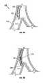
- FIGS. 2A-2Care side views of variations of the invention having an electrically conductive tip which is able to function as a Doppler tip as well as create the collateral channels.
- FIGS. 3A-3Dillustrate examples of tip configurations of the present invention.
- FIGS. 4A-4Billustrate cross sectional views of examples of transducer assemblies of the present invention.
- FIGS. 5A-5Eillustrate various configurations used to deliver energy to the tip of the inventive device.
- FIGS. 6A-6Bshow sectional views of the inventive device where a conductive medium also serves to attach a tip to the device.
- FIGS. 7A-7Eillustrate various configurations to retain a tip to devices of the present invention.
- FIG. 8illustrates an insulating layer on the device.
- FIGS. 9A-9Cshows the device when used to create a collateral channel in the airways of the lung.
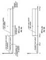
- FIGS. 10A-10Billustrate time-of-flight diagrams for the Doppler echo signal used to determine the Doppler control settings.
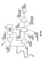
- FIG. 10Cillustrates an example of a schematic representation of a pulsed wave Doppler electronic system for use with the inventive device.
- FIGS. 1A-1CPrior to considering the invention, simplified illustrations of various states of a natural airway and a blood gas interface found at a distal end of those airways are provided in FIGS. 1A-1C .
- FIG. 1Ashows a natural airway 100 which eventually branches to a blood gas interface 102 .
- FIG. 1Billustrates an airway 100 and blood gas interface 102 in an individual having COPD.
- the obstructions 104e.g., excessive mucus resulting from COPD, see above impair the passage of gas between the airways 100 and the interface 102 .
- FIG. 1Ashows a natural airway 100
- FIGS. 1A-1Cillustrates a portion of an emphysematous lung where the blood gas interface 102 expands due to the loss of the interface walls 106 which have deteriorated due to a bio-chemical breakdown of the walls 106 . Also depicted is a constriction 108 of the airway 100 . It is generally understood that there is usually a combination of the phenomena depicted in FIGS. 1A-1C . More usually, the states of the lung depicted in FIGS. 1B and 1C are often found in the same lung.
- lung tissueis intended to include the tissue involved with gas exchange, including but not limited to, gas exchange membranes, alveolar walls, parenchyma and/or other such tissue.
- the collateral channelsallow fluid communication between an airway and lung tissue. Therefore, gaseous flow is improved within the lung by altering or redirecting the gaseous flow within the lung, or entirely within the lung.
- FIG. 1Dillustrates a schematic of a lung 118 to demonstrate a benefit of the production and maintenance of collateral openings or channels through airway walls.
- a collateral channel 112located in an airway wall 110 ) places lung tissue 116 in fluid communication with airways 100 allowing expired air to directly pass out of the airways 100 .
- the term channelis intended to include an opening, cut, slit, tear, puncture, or any other conceivable artificially created opening.
- constricted airways 108may ordinarily prevent air from exiting the lung tissue 116 .
- conduitsmay be placed in the collateral channels 112 to assist in maintaining the patency of the collateral channels 112 .
- Examples of conduitsmay be found in the applications discussed above. While there is no limit to the number of collateral channels which may be created, it is preferable that 1 or 2 channels are placed per lobe of the lung. For example, the preferred number of channels is 2-12 channels per individual patient. In current trials, it was found that 1-4 channels placed per lobe of the lung and 4-16 channels per individual patient was preferable. This number may vary on a case by case basis. For instance, in some cases an emphysematous lung may require 3 or more collateral channels in one or more lobes of the lung.
- the devices of the present inventionare configured to locate a target site for creation of a collateral channel in the tissue and to create an opening in tissue. As discussed above, a benefit of this combination feature is that a single device is able to select a target location and then create an opening without having been moved. Although the device is discussed as being primarily used in the lungs, the device is not limited as such and it is contemplated that the invention has utility in other areas as well, specifically in applications in which blood vessels or other structures must be avoided while cutting or removing tissue (one such example is tumor removal.)
- the present inventionincludes the use of a device which is able to detect the presence or absence of a blood vessel by placing a front portion of the device in contact with tissue.
- One variation of the inventionincludes the use of Doppler ultrasound to detect the presence of blood vessels within tissue.
- the frequency of the signalsis not limited to the ultrasonic range, for example the frequency may be within the range of human hearing, etc.
- the ultrasound Doppleroperates at any frequency in the ultrasound range but preferably between 2 Mhz-30 Mhz. It is generally known that higher frequencies provide better resolution while lower frequencies offer better penetration of tissue. In the present invention, because location of blood vessels does not require actual imaging, there may be a balance obtained between the need for resolution and for penetration of tissue. Accordingly, an intermediate frequency may be used (e.g., around 8 Mhz).
- a variation of the inventionmay include inserting a fluid into the airway to provide a medium for the Doppler sensors to couple to the wall of the airway to detect blood vessels. In those cases where fluid is not inserted, the device may use mucus found within the airway to directly couple the sensor to the wall of the airway.
- FIG. 2Aillustrates a variation of a device 200 of the present invention where a tip 204 of the device has a conductive portion, (e.g., is made from a conductive material or has a conductive coating) allowing the tip to serve as both an acoustic lens and an RF electrode.
- the tip 204is connected to an RF generator 188 for creating channels within tissue and a transducer assembly 202 is placed in communication with an analyzing device 190 that is adapted to measure the Doppler shift between generated and reflected signals.
- the transducer assembly 202may be a transducer or a transducer coupled with a covering and other components.
- the tip 204may be separated from the transducer 202 , but both the tip 204 and transducer 202 are in acoustic communication through the use of a separation medium 211 .
- the separation medium 211transmits signals between the tip 204 and the transducer 202 .
- the spacing of the transducer 202 from the tip 204serves to prevent heat or RF energy from damaging the transducer 202 . It is intended that the spacing between the transducer 202 and tip 204 shown in the figures is for illustration purposes only. Accordingly, the spacing may vary as needed.
- the separation mediummust have acceptable ultrasound transmission properties and may also serve to provide additional thermal insulation as well. For example, an epoxy as describe herein, may be used for the separation medium.
- inventive devicemay create openings in tissue using any type of energy capable of removing/ablating tissue.
- energycapable of removing/ablating tissue.
- RF energyor a focused ultrasound may be used.
- FIG. 2Billustrates a sectional side view of a variation of the inventive device 200 .
- the device 200includes a transducer assembly 202 .
- an electrically conductive tip 204is adjacent to the transducer assembly 202 and at a distal end of the elongate member 218 .
- the transducer assembly 202is located towards a distal portion of the elongate member 218 .
- the transducer assembly of any variation of the present inventionmay be located within the elongate member, or it may be located within a portion of the tip of the device. In any case, the transducer assembly will be located towards the distal portion of the elongate member.
- the elongate member 218 of the present inventionmay or may not have a lumen extending therethrough.
- the elongate member described hereinmay be comprised of any commercially available medical-grade flexible tubing.
- the elongate membermay be selected from material that provides insulation from the heat generated by the device.
- the elongate membermay comprise a PTFE material.
- the elongate memberwill provide insulation for tissue that is adjacent to the area where creation of a collateral channel is desired. Also, in some cases, insulation may be required to prevent damage to the transducer assembly.
- the device 200further includes a first conducting member 220 and a second conducting member 222 (e.g., wires) both extending through at least a portion of elongate member 218 to the transducer assembly 202 .
- the conducting members 220 , 222may extend through a lumen of the elongate member 218 or may extend in the wall of the elongate member 218 .
- the conducting members 220 , 220provide the energy and controls for the transducer assembly 202 .
- the conducting members 220 , 222may be coupled to an ultrasound source 190 .
- variations of the inventive deviceinclude conducting members 220 , 222 which may be comprised of a series of wires, with one set of wires being coupled to respective poles of the transducer, and any number of additional sets of wires extending through the device.
- the wiresenable the device to couple to energy and control units.
- the device 200may also include an outer sheath (not shown in FIG. 2B ) in which the device 200 may be advanced to a target tissue site.
- FIG. 2Cillustrates another variation of a device 200 for creating collateral channels.
- a transducer assembly 202is provided with a conductive tip 204 having a flatter front surface 240 .
- the tip 204is located adjacent to a covering 206 of the transducer assembly 202 .
- the transducer assembly 202is located towards a distal portion of the elongate member 218 .
- the device 200also includes an (optional) outer sheath 226 .
- the conductive tip 204may be coupled to an energy source 188 using one of the conducting members 220 or 222 . In such a case, the tip 204 will be electrically coupled to one of the conducting members.
- the transducer assemblyis adapted to generate a source signal and receive a reflected signal
- variations of the inventionmay omit the transducer covering and other structures not necessary to generate a source signal and receive a reflected signal. Therefore, it is contemplated that the invention may simply have a transducer that is coupled to a controller.
- FIGS. 3A-3Dillustrate possible variations of the tip 204 of the device. It is noted that these variations are provided for illustrative purposes and are not meant to be exhaustive.
- the tips 204 of the present inventionmay function as a lens to disperse and/or direct a signal over a substantial portion of the outer surface of the tip 204 .
- the tip 204also is adapted to disperse and/or direct (e.g., by diffraction) a reflected signal towards the transducer (not shown in FIGS. 3A-3D ). Accordingly, given the above described configuration, the inventive device 200 will be able to detect vessels with substantially most of the tip 204 .
- this device 200may detect vessels through a greater range of motion (e.g., as opposed to requiring the device 200 to be orthogonal to the tissue.) Furthermore, the tip may comprise a directing means.
- the tip 204is designed such that it interferes and redirects the signals in a desired direction in a manner like a lens. It also may be desirable to place an epoxy between the tip 204 and the transducer. Preferably, the epoxy is thin and applied without air gaps, bubbles or pockets. Also, the density/hardness of the epoxy should provide for transmission of the signal while minimizing any effect or change to the source signal.
- the configuration of the transducer assembly 202permits the tip 204 to disperse a signal over a substantial portion of its outer surface 240 .
- the tip 204also is adapted to refract a reflected signal towards the transducer 208 . Accordingly, given the above described configuration, the inventive device will be able to detect vessels with any part or substantially all of the lens 204 that contacts tissue.
- the tipis of the present invention is able to transmit a source signal and receive a reflected signal
- the inventionis not limited to requiring both functions.
- the inventive devicecould be configured to generate a source signal and direct the source signal to an area of interest but a second device or transducer assembly could be used to receive the reflected signal.
- a separate devicecould be used to generate the source signal with the inventive device being used to receive the reflected signal.
- the inventioncontemplates the tip 204 as comprising an electrically conductive material such that energy (e.g., RF energy or thermal energy) may be delivered to the tissue via the tip 204 .
- the tipmay comprise titanium, aluminum, or stainless steel, etc. any electrically conductive metal.
- the tip 204may be comprised of any material suitable for ultrasound applications but is not particularly electrically conductive. In such a case, the tip will have an electrically conductive coating about at least a portion of the tip.
- These tip materialsinclude dimethyl pentene, a methylpentene copolymer (plastic-TPX), carbon aerogel, polycarbonate (e.g., Lexan), polystyrene, etc.
- Electrically conductive coatingsinclude gold, silver, tantalum, copper, chrome, or any bio-compatible electrically conductive material, etc. This material may be coated, deposited, plated, painted, wound, wrapped (e.g., a conductive foil), etc. onto the tip 204 .
- the tip 204 of the present inventionis selected to be long enough to avoid excessive heating of the transducer 208 and at a length that minimizes the signal clutter resulting from the use of material.
- Nany integer
- FIGS. 3A-3DA measurement of the tip lengths 242 may be seen in FIGS. 3A-3D .
- FIG. 3Aillustrates a variation of the tip 204 having a rounded front surface 240 .
- the tip length 242 of the entire tipmay be selected such that N is an odd integer (e.g., 9) and the length behind the front surface 244 may be selected to be any integer multiple of the wavelength (e.g., 6 or 7).
- the tip 204may have other profiles as well. For example, it is desirable that the tip 204 produce a certain amount of divergence of the signal being passed therethrough. However, depending on a variety of factors (e.g., material, frequency of the signal, etc.) a tip 204 may encounter excessive divergence which is destructive to the outgoing signal. Accordingly, it may be desirable to produce a tip 204 as illustrated in FIG. 3B in which a front surface 240 of the tip 204 is substantially flat.
- FIG. 3Cillustrates another variation of a tip 204 having a rounded front surface 240 but with no projections on the sides of the tip 204 .
- FIG. 3Dillustrates a tip 204 with a concave front surface 240 .
- the deviceis configured such that there are no exposed sharp edges that may cause any unintended damage to tissue while the device is being used to determine the presence or absence of a blood vessel.
- the tipmay be designed such that it doesn't have sharp edges, or any sharp edges may be covered by other parts of the device (e.g., the elongate member, an outer sheath, etc.)
- the inventionmay be any size, it was found that an overall device diameter of 0.071′′ was acceptable. As noted, because the device is advanced through the airways, the device may treat deeper areas in the airways of the lungs given a smaller outside diameter of the distal end of the device. This size also permits delivery of the device into the lungs through the working channel of a standard bronchoscope or endoscope. However, this reduction in size is limited as functionality of the device may suffer. For example, one or more wires will be selected such that they will deliver sufficient RF energy over a desired period of time without experiencing unacceptable heating. Therefore, the smallest acceptable cross sectional area of a single wire or multiple wires will be a balance of the energy delivery requirements of the device versus the characteristics of the wire or wires.
- FIGS. 4A-4Billustrate variations of the transducer assembly 202 which are configured to reduce an overall size of the assembly.
- FIG. 4Aillustrates a cross-sectional view of a basic variation of a transducer assembly 202 for use with the present invention.
- the transducer assembly 202 illustrated in FIG. 4Ais shown without a tip.
- the transducer assembly 202includes at least one transducer 208 (e.g., a piezoelectric transducer.)
- the front surface of the transducer 208comprises a first pole and the rear surface comprises a second pole.
- the transducer or transducersmay comprise a piezo-ceramic crystal (e.g., a Motorola PZT 3203 HD ceramic).
- a single-crystal piezo (SCP)is preferred, but the invention does not exclude the use of other types of ferroelectric material such as poly-crystalline ceramic piezos, polymer piezos, or polymer composites.
- the substratetypically made from piezoelectric single crystals (SCP) or ceramics such as PZT, PLZT, PMN, PMN-PT; also, the crystal may be a multi layer composite of a ceramic piezoelectric material. Piezoelectric polymers such as PVDF may also be used.
- Micromachined transducerssuch as those constructed on the surface of a silicon wafer are also contemplated (e.g., such as those provided by Sensant of San Leandro, Calif.)
- the transducer or transducers usedmay be ceramic pieces coated with a conductive coating, such as gold.
- Other conductive coatingsinclude sputtered metal, metals, or alloys, such as a member of the Platinum Group of the Periodic Table (Ru, Rh, Pd, Re, Os, Ir, and Pt) or gold. Titanium (Ti) is also especially suitable.
- the transducermay be further coated with a biocompatible layer such as Parylene or Parylene C.
- the covering 206 of the transducer assembly 202contains the transducer 208 .
- the covering 206may comprise a conductive material. In such cases the covering 206 itself becomes part of the electrical path to the first pole of the transducer 208 .
- Use of a conductive covering 206may require insulating material 213 between the sides of the transducer 208 , thereby permitting a first conductive medium 214 to electrically couple only one pole of the transducer 208 to the covering 206 .
- the conductive medium 214permits one of the poles of the transducer 208 to be placed in communication with a conducting member that is ultimately coupled to a power supply. As shown in this example, the conductive medium 214 places the pole of the transducer 208 in electrical communication with the covering 206 . In some variations the conductive medium 214 may coat the entire transducer 208 and covering 206 . Alternatively, the conductive medium 214 may be placed over an area small enough to allow for an electrical path between a conducting member and the respective pole of the transducer 208 .
- the conductive medium 214may be any conductive material (e.g., gold, silver, tantalum, copper, chrome, or any bio-compatible conductive material, etc.
- the materialmay be coated, deposited, plated, painted, wound, wrapped (e.g., a conductive foil), etc. onto the transducer assembly 202 .
- the transducer assembly 202 depicted in FIG. 4Aalso illustrates conducting members 220 , 222 electrically coupled to respective poles of the transducer 208 .
- the conducting members 220 , 222may be encapsulated within an epoxy 211 located within the covering 206 .
- the epoxy 211may extend to the transducer 208 thereby assisting in retaining both the conducting members 220 , 222 and transducer 208 within the covering. It may also be desirable to maintain a gap 228 between the transducer 208 and any other structure. It is believed that this gap 228 improves the ability of the transducer assembly 202 to generate a signal.
- FIG. 4Billustrates another variation of a transducer assembly 202 .
- the conductive medium 214extends over the entire transducer covering 206 .
- the covering 206may be made of a non-conducting material (e.g., a polyamide tube, polyetherimide, polycarbonate, etc.)
- the transducer assembly 202may further comprise a second tube 216 within the covering 206 .
- This second tube 216may be a hypo-tube and may optionally be used to electrically couple one of the conducting members to a pole of the transducer 208 .
- the covering 206may contain a non-conductive epoxy 210 (e.g., Hysol 2039/3561 with Scotchlite glass microspheres B23/500) which secures both the conducting member and the second tube 216 within the covering 206 .
- This constructionmay have the further effect of structurally securing the transducer 208 within the assembly 202 .
- a gap 228may or may not be adjacent to the transducer to permit displacement of the transducer 208 .
- FIG. 4Balso illustrates the assembly 202 as having a conductive epoxy 212 which encapsulates the alternate conducting member 220 .
- a conductive epoxyis Bisphenol epoxy resin with silver particulates to enable conductivity. The particulates may be from 70-90% of the resin composition.
- the resinmay then be combined with a hardener (e.g., 100 parts resin per 6 parts hardener.)
- the conductive epoxy 212is in electrical communication with the conductive medium 214 allowing for a conductive path from the conducting member 220 to the conductive medium 214 . Accordingly, use of the conductive epoxy 212 secures the conducting member 220 to the assembly 202 while electrically coupling the conducting member 220 to the transducer via the conductive coating 214 .
- FIG. 5Aillustrates a variation of the inventive device 200 having a conductive tip 204 located at the front of the transducer assembly 202 .
- the conductive tip 204may have a third conducting member (e.g., a wire) electrically coupled directly to the conductive tip 204 .
- this configurationrequires an elongate member 218 with a diameter larger than that of the transducer assembly 202 to accommodate a wire along side of the transducer assembly 202 . It may be desirable to minimize the diameter of the transducer assembly 202 so that the device 200 may fit within the working channel of a bronchoscope or other endoscope.
- FIG. 5Billustrates another variation of the inventive device 200 which attempts to minimize the size of the elongate sheath 218 .
- the transducer assembly 202may have an outer perimeter that is smaller than an inner perimeter of a lumen of the elongate member 218 such that the third conducting member 250 extends along the lumen and parallel to the transducer assembly 202 .
- FIG. 5Cwhich is a side view of the variation of FIG. 5B , this variation of the transducer assembly 202 has a non-circular shape to permit passage of the third conducting member 250 along the side of the transducer assembly 202 .
- the elongate member 218may have a retaining epoxy 230 placed within the elongate member 218 to secure the third conducting member 250 and to seal any opening in the distal end caused by the difference in size between the transducer assembly 202 and the elongate member 218 .
- FIG. 5Dillustrates another variation used to minimize the size of the device.
- FIG. 5Donly illustrates the transducer assembly 202 , conducting members 220 , 222 , tip 204 , and transducer 208 (hidden lines.)
- the transducer assembly 202will have a conductive medium (not shown) placed on an outside surface.
- FIG. 5Dillustrates a second conductive medium 254 placing the tip 204 in electrical communication with the first conductive medium (not shown.)
- This configurationpermits delivery of energy to the tip 204 via one of the conducting members 220 or 222 . Therefore, the need for a separate conducting member is eliminated.
- the amount of second conductive medium 254is shown for illustrative purposes only.
- a second conductive medium 254When using a second conductive medium 254 to provide the energy supply to a conductive tip 204 it may be desirable to provide a conductive medium 254 of sufficient thickness so that the energy delivered to the tip 204 does not produce unwanted heating of the overall transducer assembly 202 .
- conducting member(s)were sized to provide sufficient energy while minimizing heating of the member.
- the deviceused gold foils having a thickness ranging from 2-10 microns.
- FIG. 5Eillustrates a variation of the device where the tip 204 of the transducer assembly 202 is covered with the second conductive material 254 .
- a tip 204that is not bio-compatible.
- a tip 204 comprised of aluminummay offer excellent acoustic characteristics.
- an aluminum tip 204may not offer the desired bio-compatibility.
- coating the tip 204 with the second conductive material 254 where it is exposed to tissuemay provide the desired bio-compatibility characteristics.
- FIG. 6Aillustrates a variation of the inventive device where the second conductive medium is formed from a spring 260 .
- the spring 260may be formed from one or more spring wound wires.
- the wire(s) forming the spring 260may extend through the device but ultimately couple to an energy source.
- the spring 260may be coupled to the covering 206 or one of the conducting members for delivery of the energy through the spring 260 to the tip 204 .
- the spring 260may optionally be secured (e.g., crimped, welded, soldered, glued, or reduced in diameter) about the tip 204 as additional means to retain the tip 204 .
- a beneficial feature of the spring 260is that it provides additional flexibility to the end of the device when articulated in a bronchoscope.
- FIG. 6Billustrates another variation of the inventive device 200 .
- the second conductive mediumcomprises a tube 262 .
- the tube 262may be independently connected to an energy source via a third conducting member 250 (as illustrated.) In such cases, it may be necessary to insulate respective portions of the tube 262 from parts of the transducer assembly 202 .
- the tube 262may be in electrical communication with a portion of the transducer assembly 202 which supplies the energy to the tip 204 .
- the tube 262may optionally be secured (e.g., crimped, or reduced in diameter) about the tip 204 .
- the tube 262may have a cross-sectional shape to match the outer shape of the transducer assembly 202 (e.g., circular, oval, rectangular, etc.)
- the tube 262may be a hypo-tube comprised of any conductive and preferably bio-compatible material.
- FIGS. 7A-7Eillustrate examples of configurations for redundant joints to retain the tip 204 with the device by increasing the retention strength of the tip 204 within the device. It is contemplated that these concepts may be combined as necessary with the variations of the invention disclosed herein.
- FIG. 7Aillustrates a tip 204 attached to the transducer assembly 202 .
- the tip 204may be bonded, via a retaining epoxy 230 , to either the transducer 208 or to the first conductive medium, such as a gold coating, etc. (not shown.)
- the retaining epoxy 230should be selected to minimize any interference to the source or return signal. Examples of the retaining epoxy 230 include Epotech 301, Epotech 353, Epotech 377, provided by Epoxy Technology, Inc., Bellerica, Mass. As illustrated in FIG.
- the retaining epoxy 230may run along the sides of the transducer assembly 202 in which case the epoxy 230 may adhere to the elongate member (not shown.) Moreover, the tip 204 may be machined, etched, etc., to contain a plurality of small grooves 232 for seating the retaining epoxy 230 . Such a configuration increases the retention strength of the tip 204 within the device and is shown in FIG. 7B which illustrates a magnified view of the section marked 7 B found in FIG. 7A . Although not shown, the epoxy 230 may be placed on a lip 234 of the lens 204 . In such cases, the epoxy 230 may also adhere to a front end of the elongate member (not shown.)
- FIG. 7Cillustrates another variation where the tip 204 has a single groove 246 for better retention of the tip 204 in the device.
- the grooves discussed hereinmay either extend around the entire perimeter of the tip 204 or they may extend over only portions of the tip 204 .
- the term ‘groove’is intended to include structures such as: dimples, furrows, indentations, pockets, notches, recesses, voids, etc.
- the elongate memberis not illustrated in these figures.
- FIG. 7Dillustrates a variation of a tip 204 having at least one rib 248 which may provide a friction fit with the elongate member 218 .
- the rib 248may be deformable or rigid.
- FIG. 7Eillustrates another variation of the invention where the tip has a at least one grove 246 where the elongate member 218 is either crimped or filled into the groove 246 .
- the elongate member 218may also be reformed using heat such that it forms/flows into the groove 246 .
- FIG. 8illustrates a variation of the device 200 with an insulating layer 264 on the distal end of the device 200 .
- the insulating layer 264may be a coating, sleeve, etc. which prevents heat generated by the device from adversely affecting either tissue or the transducer assembly.
- the insulating layer 264may extend over a limited area of the device as needed. Examples of the insulating layer 264 materials include polyimide, silicone, PTFE, FEP, PFA.
- FIG. 9A-9Cillustrates use of the device within a lung to create a collateral channel in the airway wall tissue.
- FIG. 9Aillustrates the advancement of an access device 120 into the airways 100 of a lung.
- the access devicemay be a bronchoscope, endoscope, endotracheal tube with or without vision capability, or any type of delivery device.
- the access device 120will have at least one lumen or working channel 122 .
- the access device 120will locate an approximate site 114 for creation of a collateral channel.
- the access device 120is equipped so that the surgeon may observe the site for creation of the collateral channel.
- the access device 120as well as the other devices discussed herein, may be configured for detection by the particular non-invasive imaging technique such as fluoroscopy, “real-time” computed tomography scanning, or other technique being used.
- FIG. 9Billustrates a variation of the inventive device 200 advanced through the channel 122 of the access device 120 towards the site 114 .
- the site 114is then inspected to determine whether a blood vessel is adjacent to the site.
- FIG. 9Cillustrates the creation of a collateral channel 112 .
- the device 200may be manipulated to a position that is optimal for creation of the collateral channel 112 .
- the access device 120 or the inventive device 200may be steerable. Such a feature may assist in the positioning of any of the devices used in the inventive method.
- it is desirable to create the collateral channelsuch that it is in fluid communication with an air-sac. The fluid communication allows for the release of trapped gasses from the hyper-inflated lung.
- the inventive deviceis configured to communicate with an analyzing device or control unit 190 adapted to recognize the reflected signal or measure the Doppler shift between the signals.
- the source signalmay be reflected by changes in density between tissue. In such a case, the reflected signal will have the same frequency as the transmitted signal. When the source signal is reflected from blood moving within a vessel, the reflected signal has a different frequency than that of the source signal.
- This Doppler effectpermits determination of the presence or absence of a blood vessel within tissue.
- the devicemay include a user interface which allows the user to determine the presence or absence of a blood vessel at the target site. Typically, the user interface provides an audible confirmation signal.
- the confirmation signalmay be manifested in a variety of ways (e.g., light, graphically via a monitor/computer, etc.)
- the transducer assembly of the inventionis intended to include any transducer assembly that allows for the observation of Doppler effect, e.g., ultrasound, light, sound etc.
- the selection of the tip lengthsets an important parameter for design of the Doppler pulse length and range gate so that excessive echo signal clutter caused by the use of titanium is reduced before the arrival of the echo signals from the area of interest.
- the transmit pulse lengthis set to be less than the acoustic travel time for an echo signal from the area of tissue to be inspected. This setting allows the receiver to begin recovery from the transmit pulse before the first echo signal arrives at the transducer.
- the gated gain control and carrierare set based upon the time-of-flight (TOF) of a signal given pre-desired depths at which the device listens for blood vessels.
- TOFtime-of-flight
- the time for a signal to travel from the tip to and from R minequals 2R min /C tissue where C tissue equals the speed of the signal in tissue (approximately 1540 m/s).
- the time for a signal to travel back and forth through the tipwas found to be 0.44 ⁇ s. Therefore, the time for the closest echoes of interest is approximately 1.2 ⁇ s plus 0.44 ⁇ s or 1.64 ⁇ s.
- the Transmit Pulse Lengthis then set to be less than time for the closest echoes of interest, preferably about 1 ⁇ 2 of 1.64 ⁇ s or ⁇ 0.82 ⁇ s.
- the controlleris configured to listen for the first Doppler echo signal starting at the earliest time the first echo signal will return. Based upon the above example, this time is 1.64 ⁇ s.
- the Doppler echo signalsare thereafter received until a time that echoes return from the deepest area of interest (e.g., as noted above, 10 mm).
- This valueis calculated based upon the TOF from the tip to the deepest area of interest (15 ⁇ s, calculated from 2R max /C tissue .) plus the TOF through the tip (0.44 ⁇ s as discussed above.) Accordingly, Doppler signals from tissue of up to 1 cm of depth (R max ) may be received up to 15.44 ⁇ s.
- FIG. 10Billustrates the above calculated values as applied to the TOF diagram. As noted above, these values are intended to be exemplary and illustrate the methodology used in determining the timing for the Doppler system. Accordingly, these values may also be adjusted depending upon the desired depth to be examined.
- FIG. 10Cillustrates an example of a schematic representation of a pulsed wave Doppler electronic system for use with the inventive device.
- the electronics systemuses standard circuit elements.
- the timing control 281supplies timing and control signals to the Doppler transmitter 282 , the Doppler receiver 288 , and the Doppler demodulator 290 .
- the Doppler transmitter 282amplifies an applied signal applied to generate a transmit pulse which is ultimately applied to the device 200 .
- the transmit pulsehad a center frequency of 8 MHz and a pulse length of approximately 1 ⁇ s and an amplitude of 15 V peak.
- the transducer at the distal tip of the device 200converts the transmit pulse into an acoustic pulse. As the acoustic pulse travels through the tissue and blood the structures and cells produce reflections that travel back toward the probe tip and there converted from acoustic echoes to electrical echo signals 287 .
- These echo signals 287consist of a mixture of signals, some of a frequency equal to that of the transmitted signal (echoes from stationary structures in the ultrasonic field), and some echoes that are shifted in frequency by the Doppler effect.
- the echo signals 287are amplified by the Doppler receiver 288 .
- a gated gain control 284is set to start increasing gain after the transmit pulse ends but soon enough for echo signals 287 of interest to be amplified.
- the gated gain control 284lasts until echo signals 287 from the deepest structures of interest have been amplified.
- These echo signals 287are demodulated in the Doppler demodulator 290 using a gated carrier 285 in order to produce demodulated echo signals 291 that contain Doppler signals from moving blood cells at audio frequencies.
- the demodulated echo signals 291are then filtered and amplified by the Doppler audio processor 292 to improve the signal fidelity of the Doppler audio signals.
- These filtered and amplified signalsare then sent to the Audio Speaker
- the devicemay also designed to have a double shield.
- the twisted pair wires connecting the transducer assembly to the Doppler control unit 190will be shielded.
- the energy supply 188may be delivered through one of the pair of wires, the outer portion of the catheter that is exposed proximal to the working channel of an endoscope will also be shielded to prevent undesirable conduction of current.
Landscapes
- Health & Medical Sciences (AREA)
- Life Sciences & Earth Sciences (AREA)
- Engineering & Computer Science (AREA)
- Surgery (AREA)
- Biomedical Technology (AREA)
- Veterinary Medicine (AREA)
- Animal Behavior & Ethology (AREA)
- Public Health (AREA)
- Heart & Thoracic Surgery (AREA)
- General Health & Medical Sciences (AREA)
- Nuclear Medicine, Radiotherapy & Molecular Imaging (AREA)
- Medical Informatics (AREA)
- Molecular Biology (AREA)
- Vascular Medicine (AREA)
- Physics & Mathematics (AREA)
- Cardiology (AREA)
- Oral & Maxillofacial Surgery (AREA)
- Transplantation (AREA)
- Plasma & Fusion (AREA)
- Otolaryngology (AREA)
- Biophysics (AREA)
- Radiology & Medical Imaging (AREA)
- Pathology (AREA)
- Reproductive Health (AREA)
- Orthopedic Medicine & Surgery (AREA)
- Gastroenterology & Hepatology (AREA)
- Pulmonology (AREA)
- Surgical Instruments (AREA)
Abstract
Description
Zoptimum=(Ztissue×Ztransducer)^½
L=N(λ/4) forZtransducer>Ztip>Ztissue
Claims (16)
Priority Applications (9)
| Application Number | Priority Date | Filing Date | Title |
|---|---|---|---|
| US10/080,344US7422563B2 (en) | 1999-08-05 | 2002-02-21 | Multifunctional tip catheter for applying energy to tissue and detecting the presence of blood flow |
| US10/280,851US20030130657A1 (en) | 1999-08-05 | 2002-10-25 | Devices for applying energy to tissue |
| EP03713539AEP1485035A4 (en) | 2002-02-21 | 2003-02-21 | Devices for applying energy to tissue |
| PCT/US2003/004970WO2003071924A2 (en) | 2002-02-21 | 2003-02-21 | Devices for applying energy to tissue |
| AU2003217585AAU2003217585A1 (en) | 2002-02-21 | 2003-02-21 | Devices for applying energy to tissue |
| US11/015,531US20050107783A1 (en) | 1999-08-05 | 2004-12-17 | Devices for applying energy to tissue |
| US11/562,947US20110306997A9 (en) | 2002-02-21 | 2006-11-22 | Devices for creating passages and sensing for blood vessels |
| US12/323,198US20120123264A9 (en) | 2001-09-04 | 2008-11-25 | Devices for creating passages and sensing blood vessels |
| US13/670,284US20130123638A1 (en) | 1999-08-05 | 2012-11-06 | Ultrasound catheters for sensing blood flow |
Applications Claiming Priority (7)
| Application Number | Priority Date | Filing Date | Title |
|---|---|---|---|
| US14752899P | 1999-08-05 | 1999-08-05 | |
| US17614100P | 2000-01-14 | 2000-01-14 | |
| US09/633,651US6692494B1 (en) | 1999-08-05 | 2000-08-07 | Methods and devices for creating collateral channels in the lungs |
| US26913001P | 2001-02-14 | 2001-02-14 | |
| US09/908,087US20020042564A1 (en) | 1999-08-05 | 2001-07-18 | Devices for creating collateral channels in the lungs |
| US09/946,706US6749606B2 (en) | 1999-08-05 | 2001-09-04 | Devices for creating collateral channels |
| US10/080,344US7422563B2 (en) | 1999-08-05 | 2002-02-21 | Multifunctional tip catheter for applying energy to tissue and detecting the presence of blood flow |
Related Parent Applications (2)
| Application Number | Title | Priority Date | Filing Date |
|---|---|---|---|
| US09/633,651Continuation-In-PartUS6692494B1 (en) | 1999-08-05 | 2000-08-07 | Methods and devices for creating collateral channels in the lungs |
| US09/946,706Continuation-In-PartUS6749606B2 (en) | 1999-08-05 | 2001-09-04 | Devices for creating collateral channels |
Related Child Applications (2)
| Application Number | Title | Priority Date | Filing Date |
|---|---|---|---|
| US10/280,851Continuation-In-PartUS20030130657A1 (en) | 1999-08-05 | 2002-10-25 | Devices for applying energy to tissue |
| US11/562,947Continuation-In-PartUS20110306997A9 (en) | 2002-02-21 | 2006-11-22 | Devices for creating passages and sensing for blood vessels |
Publications (2)
| Publication Number | Publication Date |
|---|---|
| US20020128647A1 US20020128647A1 (en) | 2002-09-12 |
| US7422563B2true US7422563B2 (en) | 2008-09-09 |
Family
ID=46278873
Family Applications (1)
| Application Number | Title | Priority Date | Filing Date |
|---|---|---|---|
| US10/080,344Expired - LifetimeUS7422563B2 (en) | 1999-08-05 | 2002-02-21 | Multifunctional tip catheter for applying energy to tissue and detecting the presence of blood flow |
Country Status (1)
| Country | Link |
|---|---|
| US (1) | US7422563B2 (en) |
Cited By (38)
| Publication number | Priority date | Publication date | Assignee | Title |
|---|---|---|---|---|
| US20070016069A1 (en)* | 2005-05-06 | 2007-01-18 | Sorin Grunwald | Ultrasound sensor |
| US20100305428A1 (en)* | 2009-05-29 | 2010-12-02 | Medtronic, Inc. | Ultrasonic guidance of subcutaneous tunneling |
| US7846108B2 (en) | 2002-04-16 | 2010-12-07 | Vivant Medical, Inc. | Localization element with energized tip |
| US8088127B2 (en) | 2008-05-09 | 2012-01-03 | Innovative Pulmonary Solutions, Inc. | Systems, assemblies, and methods for treating a bronchial tree |
| US8172827B2 (en) | 2003-05-13 | 2012-05-08 | Innovative Pulmonary Solutions, Inc. | Apparatus for treating asthma using neurotoxin |
| US8292880B2 (en) | 2007-11-27 | 2012-10-23 | Vivant Medical, Inc. | Targeted cooling of deployable microwave antenna |
| CN102996790A (en)* | 2012-12-25 | 2013-03-27 | 西安优耐特容器制造有限公司 | Tantalum lining container |
| US8483831B1 (en) | 2008-02-15 | 2013-07-09 | Holaira, Inc. | System and method for bronchial dilation |
| US8597193B2 (en) | 2005-05-06 | 2013-12-03 | Vasonova, Inc. | Apparatus and method for endovascular device guiding and positioning using physiological parameters |
| US8608724B2 (en) | 2004-07-19 | 2013-12-17 | Broncus Medical Inc. | Devices for delivering substances through an extra-anatomic opening created in an airway |
| US8709034B2 (en) | 2011-05-13 | 2014-04-29 | Broncus Medical Inc. | Methods and devices for diagnosing, monitoring, or treating medical conditions through an opening through an airway wall |
| US8734380B2 (en) | 2007-10-22 | 2014-05-27 | Uptake Medical Corp. | Determining patient-specific vapor treatment and delivery parameters |
| US8740895B2 (en) | 2009-10-27 | 2014-06-03 | Holaira, Inc. | Delivery devices with coolable energy emitting assemblies |
| US8911439B2 (en) | 2009-11-11 | 2014-12-16 | Holaira, Inc. | Non-invasive and minimally invasive denervation methods and systems for performing the same |
| US8965490B2 (en) | 2012-05-07 | 2015-02-24 | Vasonova, Inc. | Systems and methods for detection of the superior vena cava area |
| US9050076B2 (en) | 2004-11-16 | 2015-06-09 | Uptake Medical Corp. | Device and method for lung treatment |
| US9113858B2 (en) | 2006-11-13 | 2015-08-25 | Uptake Medical Corp. | High pressure and high temperature vapor catheters and systems |
| US9119551B2 (en) | 2010-11-08 | 2015-09-01 | Vasonova, Inc. | Endovascular navigation system and method |
| US9149328B2 (en) | 2009-11-11 | 2015-10-06 | Holaira, Inc. | Systems, apparatuses, and methods for treating tissue and controlling stenosis |
| US9345532B2 (en) | 2011-05-13 | 2016-05-24 | Broncus Medical Inc. | Methods and devices for ablation of tissue |
| US9398933B2 (en) | 2012-12-27 | 2016-07-26 | Holaira, Inc. | Methods for improving drug efficacy including a combination of drug administration and nerve modulation |
| US9533128B2 (en) | 2003-07-18 | 2017-01-03 | Broncus Medical Inc. | Devices for maintaining patency of surgically created channels in tissue |
| CN106377011A (en)* | 2016-11-17 | 2017-02-08 | 温州医科大学 | Special foot pad for diabetic foot |
| US20170173275A1 (en)* | 2014-06-25 | 2017-06-22 | Massachusetts Institute Of Technology | Optical sensor for needle-tip tissue identification and diagnosis |
| US9782211B2 (en) | 2013-10-01 | 2017-10-10 | Uptake Medical Technology Inc. | Preferential volume reduction of diseased segments of a heterogeneous lobe |
| USD845467S1 (en) | 2017-09-17 | 2019-04-09 | Uptake Medical Technology Inc. | Hand-piece for medical ablation catheter |
| US10272260B2 (en) | 2011-11-23 | 2019-04-30 | Broncus Medical Inc. | Methods and devices for diagnosing, monitoring, or treating medical conditions through an opening through an airway wall |
| US10368837B2 (en) | 2005-05-06 | 2019-08-06 | Arrow International, Inc. | Apparatus and method for vascular access |
| US10485604B2 (en) | 2014-12-02 | 2019-11-26 | Uptake Medical Technology Inc. | Vapor treatment of lung nodules and tumors |
| US10531906B2 (en) | 2015-02-02 | 2020-01-14 | Uptake Medical Technology Inc. | Medical vapor generator |
| US11129673B2 (en) | 2017-05-05 | 2021-09-28 | Uptake Medical Technology Inc. | Extra-airway vapor ablation for treating airway constriction in patients with asthma and COPD |
| US11344364B2 (en) | 2017-09-07 | 2022-05-31 | Uptake Medical Technology Inc. | Screening method for a target nerve to ablate for the treatment of inflammatory lung disease |
| US11350988B2 (en) | 2017-09-11 | 2022-06-07 | Uptake Medical Technology Inc. | Bronchoscopic multimodality lung tumor treatment |
| US11419658B2 (en) | 2017-11-06 | 2022-08-23 | Uptake Medical Technology Inc. | Method for treating emphysema with condensable thermal vapor |
| US11490946B2 (en) | 2017-12-13 | 2022-11-08 | Uptake Medical Technology Inc. | Vapor ablation handpiece |
| US11504064B2 (en)* | 2016-07-28 | 2022-11-22 | Evalve, Inc. | Systems and methods for intra-procedural cardiac pressure monitoring |
| US11653927B2 (en) | 2019-02-18 | 2023-05-23 | Uptake Medical Technology Inc. | Vapor ablation treatment of obstructive lung disease |
| US12329436B2 (en) | 2019-12-03 | 2025-06-17 | Bard Peripheral Vascular, Inc. | Cauterization device for sealing pleural layers |
Families Citing this family (22)
| Publication number | Priority date | Publication date | Assignee | Title |
|---|---|---|---|---|
| US7422563B2 (en) | 1999-08-05 | 2008-09-09 | Broncus Technologies, Inc. | Multifunctional tip catheter for applying energy to tissue and detecting the presence of blood flow |
| US6749606B2 (en) | 1999-08-05 | 2004-06-15 | Thomas Keast | Devices for creating collateral channels |
| US7462162B2 (en) | 2001-09-04 | 2008-12-09 | Broncus Technologies, Inc. | Antiproliferative devices for maintaining patency of surgically created channels in a body organ |
| US7022088B2 (en) | 1999-08-05 | 2006-04-04 | Broncus Technologies, Inc. | Devices for applying energy to tissue |
| US7708712B2 (en) | 2001-09-04 | 2010-05-04 | Broncus Technologies, Inc. | Methods and devices for maintaining patency of surgically created channels in a body organ |
| US7670282B2 (en) | 2004-06-14 | 2010-03-02 | Pneumrx, Inc. | Lung access device |
| EP3542736A1 (en)* | 2004-06-16 | 2019-09-25 | PneumRx, Inc. | Intra-bronchial lung volume reduction system |
| CA2570261C (en) | 2004-07-08 | 2014-06-10 | Pneumrx, Inc. | Pleural effusion treatment device, method and material |
| US7766891B2 (en) | 2004-07-08 | 2010-08-03 | Pneumrx, Inc. | Lung device with sealing features |
| WO2006058195A2 (en) | 2004-11-23 | 2006-06-01 | Pneumrx, Inc. | Steerable device for accessing a target site and methods |
| US8888800B2 (en) | 2006-03-13 | 2014-11-18 | Pneumrx, Inc. | Lung volume reduction devices, methods, and systems |
| US8157837B2 (en) | 2006-03-13 | 2012-04-17 | Pneumrx, Inc. | Minimally invasive lung volume reduction device and method |
| US9402633B2 (en) | 2006-03-13 | 2016-08-02 | Pneumrx, Inc. | Torque alleviating intra-airway lung volume reduction compressive implant structures |
| WO2008109760A2 (en)* | 2007-03-06 | 2008-09-12 | Broncus Technologies, Inc. | Blood vessel sensing catheter having working lumen for medical appliances |
| US9173669B2 (en)* | 2008-09-12 | 2015-11-03 | Pneumrx, Inc. | Enhanced efficacy lung volume reduction devices, methods, and systems |
| WO2010135352A1 (en) | 2009-05-18 | 2010-11-25 | Pneumrx, Inc. | Cross-sectional modification during deployment of an elongate lung volume reduction device |
| US20130201796A1 (en)* | 2010-11-01 | 2013-08-08 | Nec Casio Mobile Communications, Ltd. | Electronic apparatus |
| EP2692367A3 (en)* | 2012-07-31 | 2016-03-09 | Biotronik AG | Medical device for intracorporeal use |
| WO2015061790A2 (en) | 2013-10-25 | 2015-04-30 | Pneumrx, Inc. | Genetically-associated chronic obstructive pulmonary disease treatment |
| US10390838B1 (en) | 2014-08-20 | 2019-08-27 | Pneumrx, Inc. | Tuned strength chronic obstructive pulmonary disease treatment |
| EP3606457A4 (en) | 2017-04-03 | 2021-04-21 | Broncus Medical Inc. | ELECTROSURGICAL ACCESS SHEATH |
| CN117379228B (en)* | 2022-07-04 | 2025-09-19 | 北京新尖科技有限公司 | Heart valve prosthesis |
Citations (344)
| Publication number | Priority date | Publication date | Assignee | Title |
|---|---|---|---|---|
| US2127903A (en) | 1936-05-05 | 1938-08-23 | Davis & Geck Inc | Tube for surgical purposes and method of preparing and using the same |
| US3174851A (en) | 1961-12-01 | 1965-03-23 | William J Buehler | Nickel-base alloys |
| US3351463A (en) | 1965-08-20 | 1967-11-07 | Alexander G Rozner | High strength nickel-base alloys |
| US3433226A (en) | 1965-07-21 | 1969-03-18 | Aeroprojects Inc | Vibratory catheterization apparatus and method of using |
| US3556079A (en) | 1967-05-16 | 1971-01-19 | Haruo Omizo | Method of puncturing a medical instrument under guidance of ultrasound |
| US3565062A (en) | 1968-06-13 | 1971-02-23 | Ultrasonic Systems | Ultrasonic method and apparatus for removing cholesterol and other deposits from blood vessels and the like |
| US3617060A (en) | 1967-04-10 | 1971-11-02 | Warren Iezzi | Pneumothorox-inducing hunting arrow |
| US3753700A (en) | 1970-07-02 | 1973-08-21 | Raychem Corp | Heat recoverable alloy |
| US3779234A (en) | 1971-06-30 | 1973-12-18 | Intersc Res Inst | Ultrasonic catheter with rotating transducers |
| US3823717A (en) | 1972-04-22 | 1974-07-16 | R Pohlman | Apparatus for disintegrating concretions in body cavities of living organisms by means of an ultrasonic probe |
| US3942530A (en) | 1973-09-03 | 1976-03-09 | Akademiet For De Tekniske Videnskaber, Svejsecentralen | Prostate resectoscope having ultrasonic scanning |
| US4249541A (en) | 1979-04-26 | 1981-02-10 | David S. Pratt | Biopsy device |
| US4249539A (en) | 1979-02-09 | 1981-02-10 | Technicare Corporation | Ultrasound needle tip localization system |
| US4319580A (en)* | 1979-08-28 | 1982-03-16 | The Board Of Regents Of The University Of Washington | Method for detecting air emboli in the blood in an intracorporeal blood vessel |
| US4355426A (en) | 1975-05-09 | 1982-10-26 | Macgregor David C | Porous flexible vascular graft |
| US4407294A (en) | 1982-01-07 | 1983-10-04 | Technicare Corporation | Ultrasound tissue probe localization system |
| US4431006A (en) | 1982-01-07 | 1984-02-14 | Technicare Corporation | Passive ultrasound needle probe locator |
| US4503569A (en) | 1983-03-03 | 1985-03-12 | Dotter Charles T | Transluminally placed expandable graft prosthesis |
| US4534761A (en) | 1981-08-14 | 1985-08-13 | Bentley Laboratories, Inc. | Implant device |
| US4538618A (en) | 1983-03-14 | 1985-09-03 | Lior Rosenberg | Fluid flow detector particularly useful for microvascular monitoring |
| US4582067A (en) | 1983-02-14 | 1986-04-15 | Washington Research Foundation | Method for endoscopic blood flow detection by the use of ultrasonic energy |
| US4583969A (en) | 1984-06-26 | 1986-04-22 | Mortensen J D | Apparatus and method for in vivo extrapulmonary blood gas exchange |
| US4658817A (en) | 1985-04-01 | 1987-04-21 | Children's Hospital Medical Center | Method and apparatus for transmyocardial revascularization using a laser |
| US4674498A (en) | 1983-07-06 | 1987-06-23 | Everest Medical Corporation | Electro cautery surgical blade |
| US4676782A (en) | 1984-09-21 | 1987-06-30 | Vitaphore Corporation | Positionable tissue interfacing device for the management of percutaneous conduits |
| US4682596A (en) | 1984-05-22 | 1987-07-28 | Cordis Corporation | Electrosurgical catheter and method for vascular applications |
| US4687482A (en) | 1984-04-27 | 1987-08-18 | Scripps Clinic And Research Foundation | Vascular prosthesis |
| US4750902A (en) | 1985-08-28 | 1988-06-14 | Sonomed Technology, Inc. | Endoscopic ultrasonic aspirators |
| US4753236A (en) | 1986-04-08 | 1988-06-28 | Healey Maureen A | Temporary anastomotic device |
| US4757822A (en) | 1985-02-07 | 1988-07-19 | Biotronix S.R.L. | Instrument to detect and represent the cross-sectional variations of a blood vessel |
| US4757821A (en) | 1986-11-12 | 1988-07-19 | Corazonix Corporation | Omnidirectional ultrasonic probe |
| US4769031A (en) | 1986-06-25 | 1988-09-06 | Mcgough Edwin C | Ventricular access device and method |
| US4770185A (en) | 1983-02-14 | 1988-09-13 | The Board Of Regents Of The University Of Washington | Method and apparatus for endoscopic blood flow detection by the use of ultrasonic energy |
| US4771788A (en) | 1986-07-18 | 1988-09-20 | Pfizer Hospital Products Group, Inc. | Doppler tip wire guide |
| US4773413A (en) | 1983-06-13 | 1988-09-27 | Trimedyne Laser Systems, Inc. | Localized heat applying medical device |
| US4785402A (en) | 1985-11-02 | 1988-11-15 | Kabushiki Kaisha Toshiba | Ultrasonic imaging apparatus for color display of flow velocity |
| US4795465A (en) | 1987-05-14 | 1989-01-03 | Hood Laboratories | Tracheobronchial stent |
| US4802476A (en) | 1987-06-01 | 1989-02-07 | Everest Medical Corporation | Electro-surgical instrument |
| US4807634A (en) | 1986-02-04 | 1989-02-28 | Kabushiki Kaisha Toshiba | Mechanical type ultrasonic scanner |
| US4808153A (en) | 1986-11-17 | 1989-02-28 | Ultramed Corporation | Device for removing plaque from arteries |
| US4834102A (en) | 1988-02-25 | 1989-05-30 | Jack Schwarzchild | Endoscope for transesophageal echocardiography |
| WO1989006515A1 (en) | 1988-01-22 | 1989-07-27 | Jonathan Bernstein | System for angioplasty and ultrasonic contrast imaging |
| US4869268A (en) | 1987-05-14 | 1989-09-26 | Inbae Yoon | Multi-functional instruments and stretchable ligating and occluding devices |
| US4870953A (en) | 1987-11-13 | 1989-10-03 | Donmicheal T Anthony | Intravascular ultrasonic catheter/probe and method for treating intravascular blockage |
| US4887606A (en)* | 1986-09-18 | 1989-12-19 | Yock Paul G | Apparatus for use in cannulation of blood vessels |
| EP0347098A2 (en) | 1988-06-13 | 1989-12-20 | Samuel Shiber | Atherectomy system with a guide-wire |
| DE3821836A1 (en) | 1988-06-29 | 1990-01-04 | Fraunhofer Ges Forschung | AERODYNAMIC WINDOW FOR A GAS LASER |
| US4892098A (en) | 1985-06-26 | 1990-01-09 | Sauer Jude S | Tubular tissue welding device without moving parts |
| US4899757A (en) | 1988-02-22 | 1990-02-13 | Intertherapy, Inc. | Ultrasound imaging probe with zero dead space |
| WO1990001300A1 (en) | 1988-08-05 | 1990-02-22 | Sonic Needle Corporation | Ultrasonic device for applying cavitation forces |
| US4917097A (en) | 1987-10-27 | 1990-04-17 | Endosonics Corporation | Apparatus and method for imaging small cavities |
| US4924863A (en) | 1988-05-04 | 1990-05-15 | Mmtc, Inc. | Angioplastic method for removing plaque from a vas |
| US4936281A (en) | 1989-04-13 | 1990-06-26 | Everest Medical Corporation | Ultrasonically enhanced RF ablation catheter |
| US4957508A (en) | 1986-10-31 | 1990-09-18 | Ube Industries, Ltd. | Medical tubes |
| US4967753A (en) | 1987-04-10 | 1990-11-06 | Cardiometrics, Inc. | Apparatus, system and method for measuring spatial average velocity and/or volumetric flow of blood in a vessel |
| US4973301A (en) | 1989-07-11 | 1990-11-27 | Israel Nissenkorn | Catheter and method of using same |
| US4977898A (en) | 1988-02-25 | 1990-12-18 | Hoffrel Instruments, Inc. | Miniaturized encapsulated ultrasonic transducer |
| US5002058A (en) | 1986-04-25 | 1991-03-26 | Intra-Sonix, Inc. | Ultrasonic transducer |
| US5030201A (en) | 1989-11-24 | 1991-07-09 | Aubrey Palestrant | Expandable atherectomy catheter device |
| US5042981A (en)* | 1986-06-25 | 1991-08-27 | Fuchelman Sociedad Anonima | Assembly comprising a surgical drape and a contour-type electrosurgical dispersive electrode, and method for its use |
| EP0443256A1 (en) | 1990-01-23 | 1991-08-28 | Urcan Medical Limited | Ultrasonic recanalization system |
| US5054483A (en) | 1989-03-06 | 1991-10-08 | Hood Laboratories | Tracheal cannulas and stents |
| US5061275A (en) | 1986-04-21 | 1991-10-29 | Medinvent S.A. | Self-expanding prosthesis |
| US5064435A (en) | 1990-06-28 | 1991-11-12 | Schneider (Usa) Inc. | Self-expanding prosthesis having stable axial length |
| US5069664A (en) | 1990-01-25 | 1991-12-03 | Inter Therapy, Inc. | Intravascular ultrasonic angioplasty probe |
| US5081993A (en) | 1987-11-11 | 1992-01-21 | Circulation Research Limited | Methods and apparatus for the examination and treatment of internal organs |
| US5100423A (en) | 1990-08-21 | 1992-03-31 | Medical Engineering & Development Institute, Inc. | Ablation catheter |
| US5105816A (en) | 1989-05-20 | 1992-04-21 | Fujitsu Limited | Method and system for making blood flow visible |
| US5105817A (en) | 1988-06-08 | 1992-04-21 | Kabushiki Kaisha Toshiba | Ultrasonic bloodstream imaging apparatus |
| US5125926A (en) | 1990-09-24 | 1992-06-30 | Laser Engineering, Inc. | Heart-synchronized pulsed laser system |
| US5127917A (en) | 1989-06-01 | 1992-07-07 | Schneider (Europe) A.G. | Probe, especially for the recanalization of occlusions, and catheter arrangement with such a probe |
| US5131394A (en) | 1990-03-28 | 1992-07-21 | Gehlbach Steve M | Ultrasonic guided needle |
| US5148809A (en) | 1990-02-28 | 1992-09-22 | Asgard Medical Systems, Inc. | Method and apparatus for detecting blood vessels and displaying an enhanced video image from an ultrasound scan |
| US5170793A (en) | 1990-02-07 | 1992-12-15 | Kabushiki Kaisha Toshiba | Ultrasonic probe |
| US5190528A (en) | 1990-10-19 | 1993-03-02 | Boston University | Percutaneous transseptal left atrial cannulation system |
| US5201316A (en) | 1991-03-18 | 1993-04-13 | Cardiovascular Imaging Systems, Inc. | Guide wire receptacle for catheters having rigid housings |
| US5209721A (en) | 1992-01-31 | 1993-05-11 | Wilk Peter J | Laparoscopic surgical device and related method |
| US5226421A (en) | 1992-03-06 | 1993-07-13 | Cardiometrics, Inc. | Doppler elongate flexible member having an inflatable balloon mounted thereon |
| US5238027A (en) | 1990-06-06 | 1993-08-24 | Asten Group, Inc. | Papermakers fabric with orthogonal machine direction yarn seaming loops |
| US5254112A (en) | 1990-10-29 | 1993-10-19 | C. R. Bard, Inc. | Device for use in laser angioplasty |
| US5257990A (en) | 1992-02-24 | 1993-11-02 | Kensey Nash Corporation | Electrosurgical catheter instrument with impacting working head and method of use |
| US5259385A (en) | 1991-12-23 | 1993-11-09 | Advanced Cardiovascular Systems, Inc. | Apparatus for the cannulation of blood vessels |
| US5261409A (en) | 1991-05-27 | 1993-11-16 | Sulzer Brothers Limited | Puncturing device for blood vessels |
| US5269326A (en) | 1991-10-24 | 1993-12-14 | Georgetown University | Method for transvenously accessing the pericardial space via the right auricle for medical procedures |
| US5273529A (en) | 1992-12-04 | 1993-12-28 | Olajire Idowu | Gastrostomy tube with expandable insertion tip |
| US5275166A (en) | 1992-11-16 | 1994-01-04 | Ethicon, Inc. | Method and apparatus for performing ultrasonic assisted surgical procedures |
| US5282824A (en) | 1990-10-09 | 1994-02-01 | Cook, Incorporated | Percutaneous stent assembly |
| US5287861A (en) | 1992-10-30 | 1994-02-22 | Wilk Peter J | Coronary artery by-pass method and associated catheter |
| US5295484A (en)* | 1992-05-19 | 1994-03-22 | Arizona Board Of Regents For And On Behalf Of The University Of Arizona | Apparatus and method for intra-cardiac ablation of arrhythmias |
| US5299578A (en) | 1990-08-02 | 1994-04-05 | B.V. Optische Industrie "De Oude Delft" | Endoscopic probe |
| US5309915A (en) | 1993-06-07 | 1994-05-10 | Mte, Inc. | Apparatus for locating veins and arteries |
| US5311871A (en) | 1993-01-12 | 1994-05-17 | Yock Paul G | Syringe with ultrasound emitting transducer for flow-directed cannulation of arteries and veins |
| US5313950A (en) | 1992-02-25 | 1994-05-24 | Fujitsu Limited | Ultrasonic probe |
| US5316001A (en)* | 1990-09-11 | 1994-05-31 | Ferek Petric Bozidar | Cardiac measurement system for measuring blood flow velocity by use of a sensor implanted inside the heart |
| US5320106A (en) | 1992-02-20 | 1994-06-14 | Fuji Photo Optical Co., Ltd. | Intracavitary diagnosing apparatus employing ultrasound |
| US5330500A (en) | 1990-10-18 | 1994-07-19 | Song Ho Y | Self-expanding endovascular stent with silicone coating |
| US5334210A (en) | 1993-04-09 | 1994-08-02 | Cook Incorporated | Vascular occlusion assembly |
| US5334183A (en) | 1985-08-28 | 1994-08-02 | Valleylab, Inc. | Endoscopic electrosurgical apparatus |
| US5339289A (en) | 1992-06-08 | 1994-08-16 | Erickson Jon W | Acoustic and ultrasound sensor with optical amplification |
| US5344420A (en) | 1991-02-13 | 1994-09-06 | Applied Medical Resources Corporation | Surgical trocar |
| US5351693A (en) | 1991-11-08 | 1994-10-04 | Baxter International Inc. | Ultrasound probe for use with transport catheter and method of making same |
| US5363852A (en) | 1992-06-19 | 1994-11-15 | Advanced Cardiovascular Systems, Inc. | Flow monitor and vascular access system with continuously variable frequency control |
| US5368035A (en) | 1988-03-21 | 1994-11-29 | Boston Scientific Corporation | Ultrasound imaging guidewire |
| US5372138A (en) | 1988-03-21 | 1994-12-13 | Boston Scientific Corporation | Acousting imaging catheters and the like |
| US5375602A (en) | 1990-10-02 | 1994-12-27 | Du-Med, B.V. | Ultrasonic instrument with a micro motor |
| US5377682A (en)* | 1991-09-05 | 1995-01-03 | Matsushita Electric Industrial Co., Ltd. | Ultrasonic probe for transmission and reception of ultrasonic wave and ultrasonic diagnostic apparatus including ultrasonic probe |
| US5380316A (en) | 1990-12-18 | 1995-01-10 | Advanced Cardiovascular Systems, Inc. | Method for intra-operative myocardial device revascularization |
| US5381795A (en) | 1993-11-19 | 1995-01-17 | Advanced Technology Laboratories, Inc. | Intraoperative ultrasound probe |
| US5383460A (en) | 1992-10-05 | 1995-01-24 | Cardiovascular Imaging Systems, Inc. | Method and apparatus for ultrasound imaging and atherectomy |
| US5383887A (en) | 1992-12-28 | 1995-01-24 | Celsa Lg | Device for selectively forming a temporary blood filter |
| WO1995002361A1 (en) | 1993-07-15 | 1995-01-26 | Zimmer Stevan D | Doppler ultrasound trigger for use with mr |
| US5385148A (en) | 1993-07-30 | 1995-01-31 | The Regents Of The University Of California | Cardiac imaging and ablation catheter |
| US5389096A (en) | 1990-12-18 | 1995-02-14 | Advanced Cardiovascular Systems | System and method for percutaneous myocardial revascularization |
| US5402792A (en) | 1993-03-30 | 1995-04-04 | Shimadzu Corporation | Ultrasonic medical apparatus |
| US5409019A (en) | 1992-10-30 | 1995-04-25 | Wilk; Peter J. | Coronary artery by-pass method |
| US5409012A (en) | 1993-12-30 | 1995-04-25 | Boston Scientific Corporation | Sample collection using catheter with expandable member |
| US5411466A (en) | 1991-09-05 | 1995-05-02 | Robert L. Hess | Apparatus for restenosis treatment |
| US5413601A (en) | 1990-03-26 | 1995-05-09 | Keshelava; Viktor V. | Tubular organ prosthesis |
| US5425739A (en) | 1989-03-09 | 1995-06-20 | Avatar Design And Development, Inc. | Anastomosis stent and stent selection system |
| US5427107A (en) | 1993-12-07 | 1995-06-27 | Devices For Vascular Intervention, Inc. | Optical encoder for catheter device |
| US5429144A (en) | 1992-10-30 | 1995-07-04 | Wilk; Peter J. | Coronary artery by-pass method |
| US5435314A (en) | 1994-03-25 | 1995-07-25 | Hewlett Packard Company | Intravascular imaging catheter tip having a dynamic radius |
| US5452733A (en) | 1993-02-22 | 1995-09-26 | Stanford Surgical Technologies, Inc. | Methods for performing thoracoscopic coronary artery bypass |
| US5454809A (en) | 1989-01-06 | 1995-10-03 | Angioplasty Systems, Inc. | Electrosurgical catheter and method for resolving atherosclerotic plaque by radio frequency sparking |
| US5454373A (en) | 1994-07-20 | 1995-10-03 | Boston Scientific Corporation | Medical acoustic imaging |
| US5456258A (en) | 1993-12-20 | 1995-10-10 | Fuji Photo Optical Co., Ltd. | Catheter type ultrasound probe |
| US5458120A (en) | 1993-12-08 | 1995-10-17 | General Electric Company | Ultrasonic transducer with magnetostrictive lens for dynamically focussing and steering a beam of ultrasound energy |
| US5464016A (en) | 1993-05-24 | 1995-11-07 | Boston Scientific Corporation | Medical acoustic imaging catheter and guidewire |
| US5466242A (en) | 1994-02-02 | 1995-11-14 | Mori; Katsushi | Stent for biliary, urinary or vascular system |
| US5465726A (en) | 1992-01-30 | 1995-11-14 | Intravascular Research Limited | Ultrasound imaging and catheters for use therein |
| US5470308A (en) | 1992-08-12 | 1995-11-28 | Vidamed, Inc. | Medical probe with biopsy stylet |
| US5474075A (en) | 1993-11-24 | 1995-12-12 | Thomas Jefferson University | Brush-tipped catheter for ultrasound imaging |
| US5484416A (en) | 1993-08-05 | 1996-01-16 | Advanced Cardiovascular Systems, Inc. | Coaxial cable vascular access system for use in various needles |
| US5485841A (en) | 1995-02-14 | 1996-01-23 | Univ Mcgill | Ultrasonic lung tissue assessment |
| US5500012A (en) | 1992-07-15 | 1996-03-19 | Angeion Corporation | Ablation catheter system |
| US5505088A (en) | 1993-08-27 | 1996-04-09 | Stellartech Research Corp. | Ultrasound microscope for imaging living tissues |
| US5514154A (en) | 1991-10-28 | 1996-05-07 | Advanced Cardiovascular Systems, Inc. | Expandable stents |
| US5520684A (en) | 1993-06-10 | 1996-05-28 | Imran; Mir A. | Transurethral radio frequency apparatus for ablation of the prostate gland and method |
| US5522822A (en) | 1992-10-26 | 1996-06-04 | Target Therapeutics, Inc. | Vasoocclusion coil with attached tubular woven or braided fibrous covering |
| US5527292A (en) | 1990-10-29 | 1996-06-18 | Scimed Life Systems, Inc. | Intravascular device for coronary heart treatment |
| US5527324A (en) | 1994-09-07 | 1996-06-18 | Krantz; Kermit E. | Surgical stent |
| US5540713A (en) | 1991-10-11 | 1996-07-30 | Angiomed Ag | Apparatus for widening a stenosis in a body cavity |
| US5545210A (en) | 1994-09-22 | 1996-08-13 | Advanced Coronary Technology, Inc. | Method of implanting a permanent shape memory alloy stent |
| US5545195A (en) | 1994-08-01 | 1996-08-13 | Boston Scientific Corporation | Interstitial heating of tissue |
| US5554118A (en) | 1991-05-24 | 1996-09-10 | Jang; G. David | Universal mode vascular catheter system |
| US5555886A (en) | 1995-09-28 | 1996-09-17 | Siemens Medical Systems, Inc. | Apparatus and method for detecting blood vessel size and direction for doppler flow measurement system |
| US5564434A (en) | 1995-02-27 | 1996-10-15 | Medtronic, Inc. | Implantable capacitive absolute pressure and temperature sensor |
| US5571180A (en) | 1992-01-10 | 1996-11-05 | Hansa Medical Products, Inc. | Tool for loading flexible flange into retainer |
| US5571086A (en) | 1992-11-02 | 1996-11-05 | Localmed, Inc. | Method and apparatus for sequentially performing multiple intraluminal procedures |
| US5573531A (en) | 1994-06-20 | 1996-11-12 | Gregory; Kenton W. | Fluid core laser angioscope |
| US5575818A (en) | 1995-02-14 | 1996-11-19 | Corvita Corporation | Endovascular stent with locking ring |
| WO1996039914A1 (en) | 1995-06-07 | 1996-12-19 | Arthrocare Corporation | System and method for electrosurgical cutting and ablation |
| US5588432A (en) | 1988-03-21 | 1996-12-31 | Boston Scientific Corporation | Catheters for imaging, sensing electrical potentials, and ablating tissue |
| US5593417A (en) | 1995-11-27 | 1997-01-14 | Rhodes; Valentine J. | Intravascular stent with secure mounting means |
| US5596989A (en) | 1993-12-28 | 1997-01-28 | Olympus Optical Co., Ltd. | Ultrasonic probe |
| US5607444A (en) | 1993-12-02 | 1997-03-04 | Advanced Cardiovascular Systems, Inc. | Ostial stent for bifurcations |
| US5615679A (en) | 1995-02-06 | 1997-04-01 | Ge Yokogawa Medical Systems, Limited | Method of displaying ultrasonic images and apparatus for ultrasonic diagnosis |
| US5618301A (en) | 1993-10-07 | 1997-04-08 | Angiomed Ag | Reducing stent, device with reducing stent and use of a reducing stent |
| WO1997017105A1 (en) | 1995-11-09 | 1997-05-15 | Femrx, Inc. | Needle myolysis system for uterine fibroids |
| WO1997017014A1 (en) | 1995-11-10 | 1997-05-15 | Nyfotek As | Surgical instrument |
| US5630837A (en) | 1993-07-01 | 1997-05-20 | Boston Scientific Corporation | Acoustic ablation |
| USD380266S (en) | 1994-12-30 | 1997-06-24 | Cook Incorporated | Implantable, actively expandable stent |
| US5645559A (en) | 1992-05-08 | 1997-07-08 | Schneider (Usa) Inc | Multiple layer stent |
| US5647871A (en) | 1995-03-10 | 1997-07-15 | Microsurge, Inc. | Electrosurgery with cooled electrodes |
| US5653746A (en) | 1994-03-08 | 1997-08-05 | Meadox Medicals, Inc. | Radially expandable tubular prosthesis |
| US5655548A (en) | 1996-09-16 | 1997-08-12 | Circulation, Inc. | Method for treatment of ischemic heart disease by providing transvenous myocardial perfusion |
| US5658279A (en) | 1993-04-30 | 1997-08-19 | Medical Scientific, Inc. | Bipolar electrosurgical trocar |
| US5658280A (en) | 1995-05-22 | 1997-08-19 | Issa; Muta M. | Resectoscope electrode assembly with simultaneous cutting and coagulation |
| US5672172A (en) | 1994-06-23 | 1997-09-30 | Vros Corporation | Surgical instrument with ultrasound pulse generator |
| US5674277A (en) | 1994-12-23 | 1997-10-07 | Willy Rusch Ag | Stent for placement in a body tube |
| US5674298A (en) | 1994-10-21 | 1997-10-07 | The Board Of Regents Of The University Of Michigan | Calcification-resistant bioprosthetic tissue and methods of making same |
| US5678555A (en) | 1996-04-08 | 1997-10-21 | O'connell; Peter | Method of locating and marking veins |
| US5693085A (en) | 1994-04-29 | 1997-12-02 | Scimed Life Systems, Inc. | Stent with collagen |
| US5704361A (en) | 1991-11-08 | 1998-01-06 | Mayo Foundation For Medical Education And Research | Volumetric image ultrasound transducer underfluid catheter system |
| US5713949A (en) | 1996-08-06 | 1998-02-03 | Jayaraman; Swaminathan | Microporous covered stents and method of coating |
| US5716393A (en) | 1994-05-26 | 1998-02-10 | Angiomed Gmbh & Co. Medizintechnik Kg | Stent with an end of greater diameter than its main body |
| US5718701A (en)* | 1993-08-11 | 1998-02-17 | Electro-Catheter Corporation | Ablation electrode |
| US5720735A (en) | 1997-02-12 | 1998-02-24 | Dorros; Gerald | Bifurcated endovascular catheter |
| US5725547A (en) | 1996-01-04 | 1998-03-10 | Chuter; Timothy A. M. | Corrugated stent |
| US5736642A (en) | 1997-01-08 | 1998-04-07 | The United States Of America As Represented By The Administrator Of The National Aeronautics And Space Administration | Nonlinear ultrasonic scanning to detect material defects |
| US5741333A (en) | 1995-04-12 | 1998-04-21 | Corvita Corporation | Self-expanding stent for a medical device to be introduced into a cavity of a body |
| US5741234A (en) | 1996-07-16 | 1998-04-21 | Aboul-Hosn; Walid Nagib | Anatomical cavity access sealing condit |
| WO1998016161A1 (en) | 1996-10-11 | 1998-04-23 | Transvascular, Inc. | Methods and apparatus for bypassing arterial obstructions and/or performing other transvascular procedures |
| US5752518A (en) | 1996-10-28 | 1998-05-19 | Ep Technologies, Inc. | Systems and methods for visualizing interior regions of the body |
| US5755769A (en) | 1992-03-12 | 1998-05-26 | Laboratoire Perouse Implant | Expansible endoprosthesis for a human or animal tubular organ, and fitting tool for use thereof |
| US5755778A (en) | 1996-10-16 | 1998-05-26 | Nitinol Medical Technologies, Inc. | Anastomosis device |
| US5759769A (en) | 1993-06-09 | 1998-06-02 | Connaught Laboratories Limited | Tandem synthetic HIV-1 peptides |
| WO1998028035A1 (en) | 1996-12-24 | 1998-07-02 | Global Therapeutics, Inc. | Radially expandable axially non-contracting surgical stent |
| US5779642A (en) | 1996-01-16 | 1998-07-14 | Nightengale; Christopher | Interrogation device and method |
| US5792119A (en) | 1992-10-27 | 1998-08-11 | Marx; Karl-Heinz | Tubular implant to be used for percutaneously feeding a patient |
| US5795325A (en) | 1991-07-16 | 1998-08-18 | Heartport, Inc. | Methods and apparatus for anchoring an occluding member |
| US5797920A (en) | 1996-06-14 | 1998-08-25 | Beth Israel Deaconess Medical Center | Catheter apparatus and method using a shape-memory alloy cuff for creating a bypass graft in-vivo |
| US5810836A (en) | 1996-03-04 | 1998-09-22 | Myocardial Stents, Inc. | Device and method for trans myocardial revascularization (TMR) |
| US5810008A (en) | 1996-12-03 | 1998-09-22 | Isg Technologies Inc. | Apparatus and method for visualizing ultrasonic images |
| US5824046A (en) | 1996-09-27 | 1998-10-20 | Scimed Life Systems, Inc. | Covered stent |
| US5830222A (en) | 1995-10-13 | 1998-11-03 | Transvascular, Inc. | Device, system and method for intersititial transvascular intervention |
| US5830191A (en) | 1992-06-30 | 1998-11-03 | Ethicon, Inc. | Flexible endoscopic surgical port |
| WO1998048706A1 (en) | 1997-04-30 | 1998-11-05 | Bradford Hospitals Nhs Trust | Occlusion device |
| US5840431A (en) | 1994-04-14 | 1998-11-24 | Fritz Borsi Kg | Method for preferably region-by-region coating of a transparent carrier plate |
| US5843175A (en) | 1997-06-13 | 1998-12-01 | Global Therapeutics, Inc. | Enhanced flexibility surgical stent |
| US5846205A (en) | 1997-01-31 | 1998-12-08 | Acuson Corporation | Catheter-mounted, phased-array ultrasound transducer with improved imaging |
| US5849037A (en) | 1995-04-12 | 1998-12-15 | Corvita Corporation | Self-expanding stent for a medical device to be introduced into a cavity of a body, and method for its preparation |
| US5855597A (en) | 1997-05-07 | 1999-01-05 | Iowa-India Investments Co. Limited | Stent valve and stent graft for percutaneous surgery |
| WO1999001076A1 (en) | 1997-07-02 | 1999-01-14 | Broncus Technologies, Inc. | Bleb reducer |
| US5860951A (en) | 1992-01-07 | 1999-01-19 | Arthrocare Corporation | Systems and methods for electrosurgical myocardial revascularization |
| US5860920A (en) | 1993-10-14 | 1999-01-19 | Ep Technologies, Inc. | Systems for locating and ablating accessory pathways in the heart |
| US5868763A (en) | 1996-09-16 | 1999-02-09 | Guidant Corporation | Means and methods for performing an anastomosis |
| US5876345A (en) | 1997-02-27 | 1999-03-02 | Acuson Corporation | Ultrasonic catheter, system and method for two dimensional imaging or three-dimensional reconstruction |
| US5876434A (en) | 1997-07-13 | 1999-03-02 | Litana Ltd. | Implantable medical devices of shape memory alloy |
| WO1999011182A1 (en) | 1997-09-04 | 1999-03-11 | The Regents Of The University Of California | Intraluminal directed ultrasound delivery device |
| WO1999025419A1 (en) | 1997-11-14 | 1999-05-27 | Fox Hollow Technologies, Inc. | Recanalization apparatus and devices for use therein and method |
| US5916158A (en)* | 1995-10-06 | 1999-06-29 | Cordis Webster, Inc. | Split tip electrode catheter |
| US5922019A (en) | 1995-11-27 | 1999-07-13 | Schneider (Europe) A.G. | Conical stent |
| US5935135A (en) | 1995-09-29 | 1999-08-10 | United States Surgical Corporation | Balloon delivery system for deploying stents |
| US5938697A (en) | 1998-03-04 | 1999-08-17 | Scimed Life Systems, Inc. | Stent having variable properties |
| US5951567A (en) | 1997-07-24 | 1999-09-14 | Cardiogenesis Corporation | Introducer for channel forming device |
| US5954649A (en) | 1997-10-20 | 1999-09-21 | Irvine Biomedical, Inc. | Catheter system having ultrasound locating capabilities |
| US5957849A (en) | 1997-06-30 | 1999-09-28 | The Regents Of The University Of California | Endoluminal ultrasound-guided resectoscope |
| US5957974A (en) | 1997-01-23 | 1999-09-28 | Schneider (Usa) Inc | Stent graft with braided polymeric sleeve |
| US5968053A (en) | 1997-01-31 | 1999-10-19 | Cardiac Assist Technologies, Inc. | Method and apparatus for implanting a graft in a vessel of a patient |
| US5967990A (en) | 1998-08-13 | 1999-10-19 | President And Fellows Of Harvard College | Surgical probe comprising visible markings on an elastic membrane |
| US5968070A (en) | 1995-02-22 | 1999-10-19 | Cordis Corporation | Covered expanding mesh stent |
| US5971980A (en) | 1995-05-02 | 1999-10-26 | Heart Rhythm Technologies, Inc. | System for controlling the energy delivered to a patient for ablation |
| US5972017A (en) | 1997-04-23 | 1999-10-26 | Vascular Science Inc. | Method of installing tubular medical graft connectors |
| US5976178A (en) | 1996-11-07 | 1999-11-02 | Vascular Science Inc. | Medical grafting methods |
| US5984871A (en) | 1997-08-12 | 1999-11-16 | Boston Scientific Technologies, Inc. | Ultrasound transducer with extended focus |
| US5993484A (en) | 1996-10-23 | 1999-11-30 | United States Surgical | Apparatus and method for dilatation of a body lumen and delivery of a prosthesis therein |
| WO1999060953A1 (en) | 1998-05-29 | 1999-12-02 | Scimed Life Systems, Inc. | Balloon expandable stent with a self-expanding portion |
| US6002955A (en) | 1996-11-08 | 1999-12-14 | Medtronic, Inc. | Stabilized electrophysiology catheter and method for use |
| US6001124A (en) | 1997-10-09 | 1999-12-14 | Vascular Science, Inc. | Oblique-angle graft connectors |
| US6004269A (en) | 1993-07-01 | 1999-12-21 | Boston Scientific Corporation | Catheters for imaging, sensing electrical potentials, and ablating tissue |
| US6003517A (en) | 1998-04-30 | 1999-12-21 | Ethicon Endo-Surgery, Inc. | Method for using an electrosurgical device on lung tissue |
| US6004273A (en) | 1997-09-22 | 1999-12-21 | Fuji Photo Optical Co., Ltd. | Ultrasound transmission medium feed device for endoscopically inserting ultrasound probe |
| US6004319A (en) | 1995-06-23 | 1999-12-21 | Gyrus Medical Limited | Electrosurgical instrument |
| US6007574A (en) | 1993-12-28 | 1999-12-28 | Pulnev; Sergei Appolonovich | Stent |
| US6007544A (en) | 1996-06-14 | 1999-12-28 | Beth Israel Deaconess Medical Center | Catheter apparatus having an improved shape-memory alloy cuff and inflatable on-demand balloon for creating a bypass graft in-vivo |
| US6010529A (en) | 1996-12-03 | 2000-01-04 | Atrium Medical Corporation | Expandable shielded vessel support |
| US6011995A (en) | 1997-12-29 | 2000-01-04 | The Regents Of The University Of California | Endovascular device for hyperthermia and angioplasty and method for using the same |
| US6013854A (en) | 1994-06-17 | 2000-01-11 | Terumo Kabushiki Kaisha | Indwelling stent and the method for manufacturing the same |
| US6013033A (en) | 1995-02-01 | 2000-01-11 | Centre National De La Recherche Scientifique | Intracavitary echographic imaging catheter |
| US6013093A (en) | 1995-11-28 | 2000-01-11 | Boston Scientific Corporation | Blood clot filtering |
| US6015405A (en) | 1998-01-20 | 2000-01-18 | Tricardia, L.L.C. | Device for forming holes in tissue |
| US6022371A (en) | 1996-10-22 | 2000-02-08 | Scimed Life Systems, Inc. | Locking stent |
| US6024703A (en) | 1997-05-07 | 2000-02-15 | Eclipse Surgical Technologies, Inc. | Ultrasound device for axial ranging |
| US6030392A (en) | 1995-01-18 | 2000-02-29 | Motorola, Inc. | Connector for hollow anatomical structures and methods of use |
| US6036702A (en) | 1997-04-23 | 2000-03-14 | Vascular Science Inc. | Medical grafting connectors and fasteners |
| US6045532A (en) | 1998-02-20 | 2000-04-04 | Arthrocare Corporation | Systems and methods for electrosurgical treatment of tissue in the brain and spinal cord |
| US6045511A (en) | 1995-02-24 | 2000-04-04 | Dipl-Ing. Lutz Ott | Device and evaluation procedure for the depth-selective, noninvasive detection of the blood flow and/or intra and/or extra-corporeally flowing liquids in biological tissue |
| US6048362A (en) | 1998-01-12 | 2000-04-11 | St. Jude Medical Cardiovascular Group, Inc. | Fluoroscopically-visible flexible graft structures |
| JP2000107178A (en) | 1998-09-30 | 2000-04-18 | Olympus Optical Co Ltd | Ultrasonic-guided paracentesis system |
| US6059731A (en) | 1998-08-19 | 2000-05-09 | Mayo Foundation For Medical Education And Research | Simultaneous side-and-end viewing underfluid catheter |
| US6059811A (en) | 1994-03-17 | 2000-05-09 | Medinol Ltd. | Articulated stent |
| US6064902A (en) | 1998-04-16 | 2000-05-16 | C.R. Bard, Inc. | Pulmonary vein ablation catheter |
| US6063111A (en) | 1998-03-31 | 2000-05-16 | Cordis Corporation | Stent aneurysm treatment system and method |
| US6070094A (en) | 1994-10-11 | 2000-05-30 | Ep Technologies, Inc. | Systems and methods for guiding movable electrode elements within multiple-electrode structures |
| US6074349A (en) | 1994-11-30 | 2000-06-13 | Boston Scientific Corporation | Acoustic imaging and doppler catheters and guidewires |
| US6074416A (en) | 1997-10-09 | 2000-06-13 | St. Jude Medical Cardiovascular Group, Inc. | Wire connector structures for tubular grafts |
| US6080109A (en) | 1997-12-09 | 2000-06-27 | Endosonics Corporation | Modular imaging/treatment catheter assembly |
| US6096053A (en) | 1996-05-03 | 2000-08-01 | Scimed Life Systems, Inc. | Medical retrieval basket |
| US6112123A (en) | 1998-07-28 | 2000-08-29 | Endonetics, Inc. | Device and method for ablation of tissue |
| US6113612A (en) | 1998-11-06 | 2000-09-05 | St. Jude Medical Cardiovascular Group, Inc. | Medical anastomosis apparatus |
| US6117101A (en) | 1997-07-08 | 2000-09-12 | The Regents Of The University Of California | Circumferential ablation device assembly |
| US6120432A (en) | 1997-04-23 | 2000-09-19 | Vascular Science Inc. | Medical grafting methods and apparatus |
| US6129726A (en) | 1992-08-12 | 2000-10-10 | Vidamed, Inc. | Medical probe device and method |
| US6135997A (en)* | 1996-03-05 | 2000-10-24 | Vnus Medical Technologies, Inc. | Method for treating hemorrhoids |
| US6143019A (en) | 1995-08-22 | 2000-11-07 | Board Of Regents, The University Of Texas System | Method for emitting therapeutic energy within tissue |
| WO2000067825A1 (en) | 1999-05-07 | 2000-11-16 | Microheart, Inc. | Apparatus and method for delivering therapeutic and diagnostic agents |
| US6152937A (en) | 1998-11-06 | 2000-11-28 | St. Jude Medical Cardiovascular Group, Inc. | Medical graft connector and methods of making and installing same |
| WO2000072908A1 (en) | 1999-06-02 | 2000-12-07 | Microheart, Inc. | Devices and methods for delivering a drug |
| US6162245A (en) | 1997-05-07 | 2000-12-19 | Iowa-India Investments Company Limited | Stent valve and stent graft |
| US6174323B1 (en) | 1998-06-05 | 2001-01-16 | Broncus Technologies, Inc. | Method and assembly for lung volume reduction |
| US6183444B1 (en) | 1998-05-16 | 2001-02-06 | Microheart, Inc. | Drug delivery module |
| US6190353B1 (en) | 1995-10-13 | 2001-02-20 | Transvascular, Inc. | Methods and apparatus for bypassing arterial obstructions and/or performing other transvascular procedures |
| WO2001013839A1 (en) | 1999-08-24 | 2001-03-01 | Spiration, Inc. | Lung reduction device, system, and method |
| US6200313B1 (en) | 1994-03-31 | 2001-03-13 | Fuji Photo Optical Co., Ltd. | Puncture instrument for punctured high frequency treatments |
| US6206831B1 (en)* | 1999-01-06 | 2001-03-27 | Scimed Life Systems, Inc. | Ultrasound-guided ablation catheter and methods of use |
| JP2001104315A (en) | 1999-10-08 | 2001-04-17 | Olympus Optical Co Ltd | Ultrasonic-guided paracentesis system device |
| WO2001028433A1 (en) | 1999-10-20 | 2001-04-26 | Spiration, Inc. | Apparatus and method for expanding the thorax |
| US6235054B1 (en) | 1998-02-27 | 2001-05-22 | St. Jude Medical Cardiovascular Group, Inc. | Grafts with suture connectors |
| US6235024B1 (en)* | 1999-06-21 | 2001-05-22 | Hosheng Tu | Catheters system having dual ablation capability |
| US6241746B1 (en) | 1998-06-29 | 2001-06-05 | Cordis Corporation | Vascular filter convertible to a stent and method |
| US6245102B1 (en) | 1997-05-07 | 2001-06-12 | Iowa-India Investments Company Ltd. | Stent, stent graft and stent valve |
| US6245020B1 (en) | 1998-01-26 | 2001-06-12 | Scimed Life System, Inc. | Catheter assembly with distal end inductive coupler and embedded transmission line |
| US6258115B1 (en) | 1997-04-23 | 2001-07-10 | Artemis Medical, Inc. | Bifurcated stent and distal protection system |
| US20010007940A1 (en) | 1999-06-21 | 2001-07-12 | Hosheng Tu | Medical device having ultrasound imaging and therapeutic means |
| US6270524B1 (en) | 1996-11-12 | 2001-08-07 | Medtronic, Inc. | Flexible, radially expansible luminal prostheses |
| US6280457B1 (en) | 1999-06-04 | 2001-08-28 | Scimed Life Systems, Inc. | Polymer covered vaso-occlusive devices and methods of producing such devices |
| US6283983B1 (en) | 1995-10-13 | 2001-09-04 | Transvascular, Inc. | Percutaneous in-situ coronary bypass method and apparatus |
| US6283951B1 (en) | 1996-10-11 | 2001-09-04 | Transvascular, Inc. | Systems and methods for delivering drugs to selected locations within the body |
| US6287290B1 (en) | 1999-07-02 | 2001-09-11 | Pulmonx | Methods, systems, and kits for lung volume reduction |
| US20010021872A1 (en) | 1999-12-31 | 2001-09-13 | Bailey Steven R. | Endoluminal cardiac and venous valve prostheses and methods of manufacture and delivery thereof |
| US6290728B1 (en) | 1998-09-10 | 2001-09-18 | Percardia, Inc. | Designs for left ventricular conduit |
| US6299635B1 (en) | 1997-09-29 | 2001-10-09 | Cook Incorporated | Radially expandable non-axially contracting surgical stent |
| US20010047180A1 (en) | 1999-03-09 | 2001-11-29 | St. Jude Medical Cardiovascular Group, Inc. | Medical grafting methods and apparatus |
| US6328689B1 (en) | 2000-03-23 | 2001-12-11 | Spiration, Inc., | Lung constriction apparatus and method |
| WO2001032088A3 (en) | 1999-11-05 | 2001-12-13 | Microheart Inc | Method and apparatus for demand injury in stimulating angiogenesis |
| US20020002401A1 (en) | 2000-06-26 | 2002-01-03 | Mcguckin James F. | Vascular device for valve leaflet apposition |
| US6336933B1 (en) | 1998-03-13 | 2002-01-08 | Juan C. Parodi | Endovascular device for application of prosthesis with sutures |
| US6344053B1 (en) | 1993-12-22 | 2002-02-05 | Medtronic Ave, Inc. | Endovascular support device and method |
| US20020022833A1 (en) | 2000-05-16 | 2002-02-21 | Maguire Mark A. | Apparatus and method incorporating an ultrasound transducer onto a delivery member |
| WO2002000278A3 (en) | 2000-06-26 | 2002-04-04 | Microheart Inc | Method and apparatus for treating ischemic tissue |
| US20020042566A1 (en) | 2000-09-29 | 2002-04-11 | Olympus Optical Co. Ltd. | Surgical operation navigation apparatus and method |
| US20020042564A1 (en) | 1999-08-05 | 2002-04-11 | Cooper Joel D. | Devices for creating collateral channels in the lungs |
| US6371964B1 (en) | 1999-05-18 | 2002-04-16 | Vascular Innovations, Inc. | Trocar for use in deploying an anastomosis device and method of performing anastomosis |
| WO2001070117A3 (en) | 2000-03-23 | 2002-04-18 | Microheart Inc | Pressure sensor for therapeutic delivery device and method |
| US20020055772A1 (en) | 2000-06-26 | 2002-05-09 | Rex Medical | Vascular device with valve for approximating vessel wall |
| US6394956B1 (en) | 2000-02-29 | 2002-05-28 | Scimed Life Systems, Inc. | RF ablation and ultrasound catheter for crossing chronic total occlusions |
| US20020087153A1 (en) | 1999-08-05 | 2002-07-04 | Broncus Technologies, Inc. | Devices for creating collateral channels |
| US20020111620A1 (en) | 2001-02-14 | 2002-08-15 | Broncus Technologies, Inc. | Devices and methods for maintaining collateral channels in tissue |
| US20020111619A1 (en) | 1999-08-05 | 2002-08-15 | Broncus Technologies, Inc. | Devices for creating collateral channels |
| US20020128647A1 (en) | 1999-08-05 | 2002-09-12 | Ed Roschak | Devices for applying energy to tissue |
| US20020138074A1 (en) | 1999-08-05 | 2002-09-26 | Thomas Keast | Devices for applying energy to tissue |
| US6490474B1 (en)* | 1997-08-01 | 2002-12-03 | Cardiac Pathways Corporation | System and method for electrode localization using ultrasound |
| US6488673B1 (en) | 1997-04-07 | 2002-12-03 | Broncus Technologies, Inc. | Method of increasing gas exchange of a lung |
| US6514249B1 (en) | 1997-07-08 | 2003-02-04 | Atrionix, Inc. | Positioning system and method for orienting an ablation element within a pulmonary vein ostium |
| US6514290B1 (en) | 2000-03-31 | 2003-02-04 | Broncus Technologies, Inc. | Lung elastic recoil restoring or tissue compressing device and method |
| US20030070676A1 (en) | 1999-08-05 | 2003-04-17 | Cooper Joel D. | Conduits having distal cage structure for maintaining collateral channels in tissue and related methods |
| US20030130657A1 (en) | 1999-08-05 | 2003-07-10 | Tom Curtis P. | Devices for applying energy to tissue |
| US6599311B1 (en) | 1998-06-05 | 2003-07-29 | Broncus Technologies, Inc. | Method and assembly for lung volume reduction |
| US6616675B1 (en) | 1996-02-02 | 2003-09-09 | Transvascular, Inc. | Methods and apparatus for connecting openings formed in adjacent blood vessels or other anatomical structures |
| US6623437B2 (en) | 2001-08-28 | 2003-09-23 | Rex Medical, L.P. | Tissue biopsy apparatus |
| US6634363B1 (en) | 1997-04-07 | 2003-10-21 | Broncus Technologies, Inc. | Methods of treating lungs having reversible obstructive pulmonary disease |
| US6712804B2 (en) | 1999-09-20 | 2004-03-30 | Ev3 Sunnyvale, Inc. | Method of closing an opening in a wall of the heart |
| US20040073155A1 (en) | 2000-01-14 | 2004-04-15 | Broncus Technologies, Inc. | Methods and devices for maintaining patency of surgically created channels in tissue |
| US6770070B1 (en) | 2000-03-17 | 2004-08-03 | Rita Medical Systems, Inc. | Lung treatment apparatus and method |
| US20040211434A1 (en) | 2002-07-05 | 2004-10-28 | Broncus Technologies, Inc. | Extrapleural airway device and method |
| US20050043751A1 (en) | 2001-09-04 | 2005-02-24 | Broncus Technologies, Inc. | Methods and devices for maintaining patency of surgically created channels in a body organ |
| US20050043752A1 (en) | 2001-09-04 | 2005-02-24 | Broncus Technologies, Inc. | Methods and devices for maintaining patency of surgically created channels in a body organ |
| US20050060044A1 (en) | 1999-08-05 | 2005-03-17 | Ed Roschak | Methods and devices for maintaining patency of surgically created channels in a body organ |
| US20050060041A1 (en) | 2001-09-04 | 2005-03-17 | Broncus Technologies, Inc. | Methods and devices for maintaining surgically created channels in a body organ |
| US20050056292A1 (en) | 1999-08-05 | 2005-03-17 | Cooper Joel D. | Devices for maintaining patency of surgically created channels in tissue |
| US20050060042A1 (en) | 2001-09-04 | 2005-03-17 | Broncus Technologies, Inc. | Methods and devices for maintaining surgically created channels in a body organ |
| US20050137715A1 (en) | 1999-08-05 | 2005-06-23 | Broncus Technologies, Inc. | Methods and devices for maintaining patency of surgically created channels in a body organ |
| US20050137611A1 (en) | 2001-09-04 | 2005-06-23 | Broncus Technologies, Inc. | Methods and devices for maintaining surgically created channels in a body organ |
| US20050137712A1 (en) | 2002-04-19 | 2005-06-23 | Michael Biggs | Devices for maintaining surgically created openings |
| US20050171527A1 (en) | 2003-12-31 | 2005-08-04 | Sumita Bhola | Circumferential ablation device assembly with an expandable member |
| US20050177144A1 (en) | 1999-08-05 | 2005-08-11 | Broncus Technologies, Inc. | Methods and devices for maintaining patency of surgically created channels in a body organ |
| US20050182475A1 (en) | 2003-09-02 | 2005-08-18 | Jimmy Jen | Delivery system for a medical device |
| US20050228268A1 (en) | 2003-07-18 | 2005-10-13 | Cary Cole | Ingestible tracking and locating device |
| US6997189B2 (en) | 1998-06-05 | 2006-02-14 | Broncus Technologies, Inc. | Method for lung volume reduction |
| US20060116749A1 (en) | 2003-07-18 | 2006-06-01 | Broncus Technologies, Inc. | Devices for maintaining patency of surgically created channels in tissue |
| US20060135984A1 (en) | 2003-07-18 | 2006-06-22 | Broncus Technologies, Inc. | Devices for maintaining patency of surgically created channels in tissue |
| US20060280773A1 (en) | 1999-08-05 | 2006-12-14 | Broncus Technologies, Inc. | Methods and devices for maintaining patency of surgically created channels in a body organ |
| US20060280772A1 (en) | 2001-09-04 | 2006-12-14 | Broncus Technologies, Inc. | Methods and devices for maintaining surgically created channels in a body organ |
Family Cites Families (2)
| Publication number | Priority date | Publication date | Assignee | Title |
|---|---|---|---|---|
| US3030392A (en)* | 1958-06-24 | 1962-04-17 | Staley Mfg Co A E | Polymers from polyepoxy acid esters and boric acid |
| US7127709B2 (en)* | 2002-09-25 | 2006-10-24 | Microsoft Corporation | System and method for jointly managing dynamically generated code and data |
- 2002
- 2002-02-21USUS10/080,344patent/US7422563B2/ennot_activeExpired - Lifetime
Patent Citations (385)
| Publication number | Priority date | Publication date | Assignee | Title |
|---|---|---|---|---|
| US2127903A (en) | 1936-05-05 | 1938-08-23 | Davis & Geck Inc | Tube for surgical purposes and method of preparing and using the same |
| US3174851A (en) | 1961-12-01 | 1965-03-23 | William J Buehler | Nickel-base alloys |
| US3433226A (en) | 1965-07-21 | 1969-03-18 | Aeroprojects Inc | Vibratory catheterization apparatus and method of using |
| US3351463A (en) | 1965-08-20 | 1967-11-07 | Alexander G Rozner | High strength nickel-base alloys |
| US3617060A (en) | 1967-04-10 | 1971-11-02 | Warren Iezzi | Pneumothorox-inducing hunting arrow |
| US3556079A (en) | 1967-05-16 | 1971-01-19 | Haruo Omizo | Method of puncturing a medical instrument under guidance of ultrasound |
| US3565062A (en) | 1968-06-13 | 1971-02-23 | Ultrasonic Systems | Ultrasonic method and apparatus for removing cholesterol and other deposits from blood vessels and the like |
| US3753700A (en) | 1970-07-02 | 1973-08-21 | Raychem Corp | Heat recoverable alloy |
| US3779234A (en) | 1971-06-30 | 1973-12-18 | Intersc Res Inst | Ultrasonic catheter with rotating transducers |
| US3823717A (en) | 1972-04-22 | 1974-07-16 | R Pohlman | Apparatus for disintegrating concretions in body cavities of living organisms by means of an ultrasonic probe |
| US3942530A (en) | 1973-09-03 | 1976-03-09 | Akademiet For De Tekniske Videnskaber, Svejsecentralen | Prostate resectoscope having ultrasonic scanning |
| US4355426A (en) | 1975-05-09 | 1982-10-26 | Macgregor David C | Porous flexible vascular graft |
| US4249539A (en) | 1979-02-09 | 1981-02-10 | Technicare Corporation | Ultrasound needle tip localization system |
| US4249541A (en) | 1979-04-26 | 1981-02-10 | David S. Pratt | Biopsy device |
| US4319580A (en)* | 1979-08-28 | 1982-03-16 | The Board Of Regents Of The University Of Washington | Method for detecting air emboli in the blood in an intracorporeal blood vessel |
| US4534761A (en) | 1981-08-14 | 1985-08-13 | Bentley Laboratories, Inc. | Implant device |
| US4407294A (en) | 1982-01-07 | 1983-10-04 | Technicare Corporation | Ultrasound tissue probe localization system |
| US4431006A (en) | 1982-01-07 | 1984-02-14 | Technicare Corporation | Passive ultrasound needle probe locator |
| US4582067A (en) | 1983-02-14 | 1986-04-15 | Washington Research Foundation | Method for endoscopic blood flow detection by the use of ultrasonic energy |
| US4770185A (en) | 1983-02-14 | 1988-09-13 | The Board Of Regents Of The University Of Washington | Method and apparatus for endoscopic blood flow detection by the use of ultrasonic energy |
| US4503569A (en) | 1983-03-03 | 1985-03-12 | Dotter Charles T | Transluminally placed expandable graft prosthesis |
| US4538618A (en) | 1983-03-14 | 1985-09-03 | Lior Rosenberg | Fluid flow detector particularly useful for microvascular monitoring |
| US4773413A (en) | 1983-06-13 | 1988-09-27 | Trimedyne Laser Systems, Inc. | Localized heat applying medical device |
| US4674498A (en) | 1983-07-06 | 1987-06-23 | Everest Medical Corporation | Electro cautery surgical blade |
| US4687482A (en) | 1984-04-27 | 1987-08-18 | Scripps Clinic And Research Foundation | Vascular prosthesis |
| US4682596A (en) | 1984-05-22 | 1987-07-28 | Cordis Corporation | Electrosurgical catheter and method for vascular applications |
| US4583969A (en) | 1984-06-26 | 1986-04-22 | Mortensen J D | Apparatus and method for in vivo extrapulmonary blood gas exchange |
| US4676782A (en) | 1984-09-21 | 1987-06-30 | Vitaphore Corporation | Positionable tissue interfacing device for the management of percutaneous conduits |
| US4757822A (en) | 1985-02-07 | 1988-07-19 | Biotronix S.R.L. | Instrument to detect and represent the cross-sectional variations of a blood vessel |
| US4658817A (en) | 1985-04-01 | 1987-04-21 | Children's Hospital Medical Center | Method and apparatus for transmyocardial revascularization using a laser |
| US4892098A (en) | 1985-06-26 | 1990-01-09 | Sauer Jude S | Tubular tissue welding device without moving parts |
| US5334183A (en) | 1985-08-28 | 1994-08-02 | Valleylab, Inc. | Endoscopic electrosurgical apparatus |
| US4750902A (en) | 1985-08-28 | 1988-06-14 | Sonomed Technology, Inc. | Endoscopic ultrasonic aspirators |
| US4785402A (en) | 1985-11-02 | 1988-11-15 | Kabushiki Kaisha Toshiba | Ultrasonic imaging apparatus for color display of flow velocity |
| US4807634A (en) | 1986-02-04 | 1989-02-28 | Kabushiki Kaisha Toshiba | Mechanical type ultrasonic scanner |
| US4753236A (en) | 1986-04-08 | 1988-06-28 | Healey Maureen A | Temporary anastomotic device |
| US5061275A (en) | 1986-04-21 | 1991-10-29 | Medinvent S.A. | Self-expanding prosthesis |
| US5002058A (en) | 1986-04-25 | 1991-03-26 | Intra-Sonix, Inc. | Ultrasonic transducer |
| US5042981A (en)* | 1986-06-25 | 1991-08-27 | Fuchelman Sociedad Anonima | Assembly comprising a surgical drape and a contour-type electrosurgical dispersive electrode, and method for its use |
| US4769031A (en) | 1986-06-25 | 1988-09-06 | Mcgough Edwin C | Ventricular access device and method |
| US4771788A (en) | 1986-07-18 | 1988-09-20 | Pfizer Hospital Products Group, Inc. | Doppler tip wire guide |
| US4887606A (en)* | 1986-09-18 | 1989-12-19 | Yock Paul G | Apparatus for use in cannulation of blood vessels |
| US4957508A (en) | 1986-10-31 | 1990-09-18 | Ube Industries, Ltd. | Medical tubes |
| US4757821A (en) | 1986-11-12 | 1988-07-19 | Corazonix Corporation | Omnidirectional ultrasonic probe |
| US4808153A (en) | 1986-11-17 | 1989-02-28 | Ultramed Corporation | Device for removing plaque from arteries |
| US4967753A (en) | 1987-04-10 | 1990-11-06 | Cardiometrics, Inc. | Apparatus, system and method for measuring spatial average velocity and/or volumetric flow of blood in a vessel |
| US4795465A (en) | 1987-05-14 | 1989-01-03 | Hood Laboratories | Tracheobronchial stent |
| US4869268A (en) | 1987-05-14 | 1989-09-26 | Inbae Yoon | Multi-functional instruments and stretchable ligating and occluding devices |
| US4802476A (en) | 1987-06-01 | 1989-02-07 | Everest Medical Corporation | Electro-surgical instrument |
| US4917097A (en) | 1987-10-27 | 1990-04-17 | Endosonics Corporation | Apparatus and method for imaging small cavities |
| US5081993A (en) | 1987-11-11 | 1992-01-21 | Circulation Research Limited | Methods and apparatus for the examination and treatment of internal organs |
| US4870953A (en) | 1987-11-13 | 1989-10-03 | Donmicheal T Anthony | Intravascular ultrasonic catheter/probe and method for treating intravascular blockage |
| WO1989006515A1 (en) | 1988-01-22 | 1989-07-27 | Jonathan Bernstein | System for angioplasty and ultrasonic contrast imaging |
| US4899757A (en) | 1988-02-22 | 1990-02-13 | Intertherapy, Inc. | Ultrasound imaging probe with zero dead space |
| US4977898A (en) | 1988-02-25 | 1990-12-18 | Hoffrel Instruments, Inc. | Miniaturized encapsulated ultrasonic transducer |
| US4834102A (en) | 1988-02-25 | 1989-05-30 | Jack Schwarzchild | Endoscope for transesophageal echocardiography |
| US5368035A (en) | 1988-03-21 | 1994-11-29 | Boston Scientific Corporation | Ultrasound imaging guidewire |
| US5372138A (en) | 1988-03-21 | 1994-12-13 | Boston Scientific Corporation | Acousting imaging catheters and the like |
| US6585655B2 (en) | 1988-03-21 | 2003-07-01 | Scimed Life Systems, Inc. | Medical imaging device |
| US6165127A (en) | 1988-03-21 | 2000-12-26 | Boston Scientific Corporation | Acoustic imaging catheter and the like |
| US5588432A (en) | 1988-03-21 | 1996-12-31 | Boston Scientific Corporation | Catheters for imaging, sensing electrical potentials, and ablating tissue |
| US4924863A (en) | 1988-05-04 | 1990-05-15 | Mmtc, Inc. | Angioplastic method for removing plaque from a vas |
| US5105817A (en) | 1988-06-08 | 1992-04-21 | Kabushiki Kaisha Toshiba | Ultrasonic bloodstream imaging apparatus |
| EP0347098A2 (en) | 1988-06-13 | 1989-12-20 | Samuel Shiber | Atherectomy system with a guide-wire |
| DE3821836A1 (en) | 1988-06-29 | 1990-01-04 | Fraunhofer Ges Forschung | AERODYNAMIC WINDOW FOR A GAS LASER |
| WO1990001300A1 (en) | 1988-08-05 | 1990-02-22 | Sonic Needle Corporation | Ultrasonic device for applying cavitation forces |
| US4920954A (en) | 1988-08-05 | 1990-05-01 | Sonic Needle Corporation | Ultrasonic device for applying cavitation forces |
| US5454809A (en) | 1989-01-06 | 1995-10-03 | Angioplasty Systems, Inc. | Electrosurgical catheter and method for resolving atherosclerotic plaque by radio frequency sparking |
| US5054483A (en) | 1989-03-06 | 1991-10-08 | Hood Laboratories | Tracheal cannulas and stents |
| US5425739A (en) | 1989-03-09 | 1995-06-20 | Avatar Design And Development, Inc. | Anastomosis stent and stent selection system |
| US4936281A (en) | 1989-04-13 | 1990-06-26 | Everest Medical Corporation | Ultrasonically enhanced RF ablation catheter |
| US5105816A (en) | 1989-05-20 | 1992-04-21 | Fujitsu Limited | Method and system for making blood flow visible |
| US5127917A (en) | 1989-06-01 | 1992-07-07 | Schneider (Europe) A.G. | Probe, especially for the recanalization of occlusions, and catheter arrangement with such a probe |
| US4973301A (en) | 1989-07-11 | 1990-11-27 | Israel Nissenkorn | Catheter and method of using same |
| US5030201A (en) | 1989-11-24 | 1991-07-09 | Aubrey Palestrant | Expandable atherectomy catheter device |
| EP0443256A1 (en) | 1990-01-23 | 1991-08-28 | Urcan Medical Limited | Ultrasonic recanalization system |
| US5069664A (en) | 1990-01-25 | 1991-12-03 | Inter Therapy, Inc. | Intravascular ultrasonic angioplasty probe |
| US5170793A (en) | 1990-02-07 | 1992-12-15 | Kabushiki Kaisha Toshiba | Ultrasonic probe |
| US5148809A (en) | 1990-02-28 | 1992-09-22 | Asgard Medical Systems, Inc. | Method and apparatus for detecting blood vessels and displaying an enhanced video image from an ultrasound scan |
| US5413601A (en) | 1990-03-26 | 1995-05-09 | Keshelava; Viktor V. | Tubular organ prosthesis |
| US5131394A (en) | 1990-03-28 | 1992-07-21 | Gehlbach Steve M | Ultrasonic guided needle |
| US5238027A (en) | 1990-06-06 | 1993-08-24 | Asten Group, Inc. | Papermakers fabric with orthogonal machine direction yarn seaming loops |
| US5064435A (en) | 1990-06-28 | 1991-11-12 | Schneider (Usa) Inc. | Self-expanding prosthesis having stable axial length |
| US5299578A (en) | 1990-08-02 | 1994-04-05 | B.V. Optische Industrie "De Oude Delft" | Endoscopic probe |
| US5100423A (en) | 1990-08-21 | 1992-03-31 | Medical Engineering & Development Institute, Inc. | Ablation catheter |
| US5316001A (en)* | 1990-09-11 | 1994-05-31 | Ferek Petric Bozidar | Cardiac measurement system for measuring blood flow velocity by use of a sensor implanted inside the heart |
| US5125926A (en) | 1990-09-24 | 1992-06-30 | Laser Engineering, Inc. | Heart-synchronized pulsed laser system |
| US5375602A (en) | 1990-10-02 | 1994-12-27 | Du-Med, B.V. | Ultrasonic instrument with a micro motor |
| US5282824A (en) | 1990-10-09 | 1994-02-01 | Cook, Incorporated | Percutaneous stent assembly |
| US5330500A (en) | 1990-10-18 | 1994-07-19 | Song Ho Y | Self-expanding endovascular stent with silicone coating |
| US5190528A (en) | 1990-10-19 | 1993-03-02 | Boston University | Percutaneous transseptal left atrial cannulation system |
| US5527292A (en) | 1990-10-29 | 1996-06-18 | Scimed Life Systems, Inc. | Intravascular device for coronary heart treatment |
| US5254112A (en) | 1990-10-29 | 1993-10-19 | C. R. Bard, Inc. | Device for use in laser angioplasty |
| US5380316A (en) | 1990-12-18 | 1995-01-10 | Advanced Cardiovascular Systems, Inc. | Method for intra-operative myocardial device revascularization |
| US5554152A (en) | 1990-12-18 | 1996-09-10 | Cardiogenesis Corporation | Method for intra-operative myocardial revascularization |
| US5389096A (en) | 1990-12-18 | 1995-02-14 | Advanced Cardiovascular Systems | System and method for percutaneous myocardial revascularization |
| US5344420A (en) | 1991-02-13 | 1994-09-06 | Applied Medical Resources Corporation | Surgical trocar |
| US5201316A (en) | 1991-03-18 | 1993-04-13 | Cardiovascular Imaging Systems, Inc. | Guide wire receptacle for catheters having rigid housings |
| US5554118A (en) | 1991-05-24 | 1996-09-10 | Jang; G. David | Universal mode vascular catheter system |
| US5261409A (en) | 1991-05-27 | 1993-11-16 | Sulzer Brothers Limited | Puncturing device for blood vessels |
| US5795325A (en) | 1991-07-16 | 1998-08-18 | Heartport, Inc. | Methods and apparatus for anchoring an occluding member |
| US5411466A (en) | 1991-09-05 | 1995-05-02 | Robert L. Hess | Apparatus for restenosis treatment |
| US5377682A (en)* | 1991-09-05 | 1995-01-03 | Matsushita Electric Industrial Co., Ltd. | Ultrasonic probe for transmission and reception of ultrasonic wave and ultrasonic diagnostic apparatus including ultrasonic probe |
| US5540713A (en) | 1991-10-11 | 1996-07-30 | Angiomed Ag | Apparatus for widening a stenosis in a body cavity |
| US5269326A (en) | 1991-10-24 | 1993-12-14 | Georgetown University | Method for transvenously accessing the pericardial space via the right auricle for medical procedures |
| US5514154A (en) | 1991-10-28 | 1996-05-07 | Advanced Cardiovascular Systems, Inc. | Expandable stents |
| US5704361A (en) | 1991-11-08 | 1998-01-06 | Mayo Foundation For Medical Education And Research | Volumetric image ultrasound transducer underfluid catheter system |
| US5351693A (en) | 1991-11-08 | 1994-10-04 | Baxter International Inc. | Ultrasound probe for use with transport catheter and method of making same |
| US5363853A (en) | 1991-11-08 | 1994-11-15 | Baxter International Inc. | Ultrasound probe for use with transport catheter and method of making same |
| US5259385A (en) | 1991-12-23 | 1993-11-09 | Advanced Cardiovascular Systems, Inc. | Apparatus for the cannulation of blood vessels |
| US6032674A (en) | 1992-01-07 | 2000-03-07 | Arthrocare Corporation | Systems and methods for myocardial revascularization |
| US5860951A (en) | 1992-01-07 | 1999-01-19 | Arthrocare Corporation | Systems and methods for electrosurgical myocardial revascularization |
| US5571180A (en) | 1992-01-10 | 1996-11-05 | Hansa Medical Products, Inc. | Tool for loading flexible flange into retainer |
| US5465726A (en) | 1992-01-30 | 1995-11-14 | Intravascular Research Limited | Ultrasound imaging and catheters for use therein |
| US5209721A (en) | 1992-01-31 | 1993-05-11 | Wilk Peter J | Laparoscopic surgical device and related method |
| US5320106A (en) | 1992-02-20 | 1994-06-14 | Fuji Photo Optical Co., Ltd. | Intracavitary diagnosing apparatus employing ultrasound |
| US5257990A (en) | 1992-02-24 | 1993-11-02 | Kensey Nash Corporation | Electrosurgical catheter instrument with impacting working head and method of use |
| US5313950A (en) | 1992-02-25 | 1994-05-24 | Fujitsu Limited | Ultrasonic probe |
| US5226421A (en) | 1992-03-06 | 1993-07-13 | Cardiometrics, Inc. | Doppler elongate flexible member having an inflatable balloon mounted thereon |
| US5755769A (en) | 1992-03-12 | 1998-05-26 | Laboratoire Perouse Implant | Expansible endoprosthesis for a human or animal tubular organ, and fitting tool for use thereof |
| US6019787A (en) | 1992-03-12 | 2000-02-01 | Laboratoire Perouse Implant | Fitting tool for use of an expansible endoprosthesis for a human or animal tubular organ |
| US5876448A (en) | 1992-05-08 | 1999-03-02 | Schneider (Usa) Inc. | Esophageal stent |
| US5645559A (en) | 1992-05-08 | 1997-07-08 | Schneider (Usa) Inc | Multiple layer stent |
| US5295484A (en)* | 1992-05-19 | 1994-03-22 | Arizona Board Of Regents For And On Behalf Of The University Of Arizona | Apparatus and method for intra-cardiac ablation of arrhythmias |
| US5339289A (en) | 1992-06-08 | 1994-08-16 | Erickson Jon W | Acoustic and ultrasound sensor with optical amplification |
| US5363852A (en) | 1992-06-19 | 1994-11-15 | Advanced Cardiovascular Systems, Inc. | Flow monitor and vascular access system with continuously variable frequency control |
| US5830191A (en) | 1992-06-30 | 1998-11-03 | Ethicon, Inc. | Flexible endoscopic surgical port |
| US5500012A (en) | 1992-07-15 | 1996-03-19 | Angeion Corporation | Ablation catheter system |
| US5470308A (en) | 1992-08-12 | 1995-11-28 | Vidamed, Inc. | Medical probe with biopsy stylet |
| US6129726A (en) | 1992-08-12 | 2000-10-10 | Vidamed, Inc. | Medical probe device and method |
| US5383460A (en) | 1992-10-05 | 1995-01-24 | Cardiovascular Imaging Systems, Inc. | Method and apparatus for ultrasound imaging and atherectomy |
| US5522822A (en) | 1992-10-26 | 1996-06-04 | Target Therapeutics, Inc. | Vasoocclusion coil with attached tubular woven or braided fibrous covering |
| US5792119A (en) | 1992-10-27 | 1998-08-11 | Marx; Karl-Heinz | Tubular implant to be used for percutaneously feeding a patient |
| US5287861A (en) | 1992-10-30 | 1994-02-22 | Wilk Peter J | Coronary artery by-pass method and associated catheter |
| US5409019A (en) | 1992-10-30 | 1995-04-25 | Wilk; Peter J. | Coronary artery by-pass method |
| US5429144A (en) | 1992-10-30 | 1995-07-04 | Wilk; Peter J. | Coronary artery by-pass method |
| US5571086A (en) | 1992-11-02 | 1996-11-05 | Localmed, Inc. | Method and apparatus for sequentially performing multiple intraluminal procedures |
| US5275166A (en) | 1992-11-16 | 1994-01-04 | Ethicon, Inc. | Method and apparatus for performing ultrasonic assisted surgical procedures |
| US5273529A (en) | 1992-12-04 | 1993-12-28 | Olajire Idowu | Gastrostomy tube with expandable insertion tip |
| US5383887A (en) | 1992-12-28 | 1995-01-24 | Celsa Lg | Device for selectively forming a temporary blood filter |
| US5311871A (en) | 1993-01-12 | 1994-05-17 | Yock Paul G | Syringe with ultrasound emitting transducer for flow-directed cannulation of arteries and veins |
| US5452733A (en) | 1993-02-22 | 1995-09-26 | Stanford Surgical Technologies, Inc. | Methods for performing thoracoscopic coronary artery bypass |
| US5402792A (en) | 1993-03-30 | 1995-04-04 | Shimadzu Corporation | Ultrasonic medical apparatus |
| US5334210A (en) | 1993-04-09 | 1994-08-02 | Cook Incorporated | Vascular occlusion assembly |
| US5658279A (en) | 1993-04-30 | 1997-08-19 | Medical Scientific, Inc. | Bipolar electrosurgical trocar |
| US5464016A (en) | 1993-05-24 | 1995-11-07 | Boston Scientific Corporation | Medical acoustic imaging catheter and guidewire |
| US5309915A (en) | 1993-06-07 | 1994-05-10 | Mte, Inc. | Apparatus for locating veins and arteries |
| US5759769A (en) | 1993-06-09 | 1998-06-02 | Connaught Laboratories Limited | Tandem synthetic HIV-1 peptides |
| US5520684A (en) | 1993-06-10 | 1996-05-28 | Imran; Mir A. | Transurethral radio frequency apparatus for ablation of the prostate gland and method |
| US6004269A (en) | 1993-07-01 | 1999-12-21 | Boston Scientific Corporation | Catheters for imaging, sensing electrical potentials, and ablating tissue |
| US5630837A (en) | 1993-07-01 | 1997-05-20 | Boston Scientific Corporation | Acoustic ablation |
| WO1995002361A1 (en) | 1993-07-15 | 1995-01-26 | Zimmer Stevan D | Doppler ultrasound trigger for use with mr |
| US5385148A (en) | 1993-07-30 | 1995-01-31 | The Regents Of The University Of California | Cardiac imaging and ablation catheter |
| US5484416A (en) | 1993-08-05 | 1996-01-16 | Advanced Cardiovascular Systems, Inc. | Coaxial cable vascular access system for use in various needles |
| US5718701A (en)* | 1993-08-11 | 1998-02-17 | Electro-Catheter Corporation | Ablation electrode |
| US5505088A (en) | 1993-08-27 | 1996-04-09 | Stellartech Research Corp. | Ultrasound microscope for imaging living tissues |
| US5618301A (en) | 1993-10-07 | 1997-04-08 | Angiomed Ag | Reducing stent, device with reducing stent and use of a reducing stent |
| US5860920A (en) | 1993-10-14 | 1999-01-19 | Ep Technologies, Inc. | Systems for locating and ablating accessory pathways in the heart |
| US5381795A (en) | 1993-11-19 | 1995-01-17 | Advanced Technology Laboratories, Inc. | Intraoperative ultrasound probe |
| US5474075A (en) | 1993-11-24 | 1995-12-12 | Thomas Jefferson University | Brush-tipped catheter for ultrasound imaging |
| US5607444A (en) | 1993-12-02 | 1997-03-04 | Advanced Cardiovascular Systems, Inc. | Ostial stent for bifurcations |
| US5427107A (en) | 1993-12-07 | 1995-06-27 | Devices For Vascular Intervention, Inc. | Optical encoder for catheter device |
| US5458120A (en) | 1993-12-08 | 1995-10-17 | General Electric Company | Ultrasonic transducer with magnetostrictive lens for dynamically focussing and steering a beam of ultrasound energy |
| US5456258A (en) | 1993-12-20 | 1995-10-10 | Fuji Photo Optical Co., Ltd. | Catheter type ultrasound probe |
| US6344053B1 (en) | 1993-12-22 | 2002-02-05 | Medtronic Ave, Inc. | Endovascular support device and method |
| US5596989A (en) | 1993-12-28 | 1997-01-28 | Olympus Optical Co., Ltd. | Ultrasonic probe |
| US6007574A (en) | 1993-12-28 | 1999-12-28 | Pulnev; Sergei Appolonovich | Stent |
| US5409012A (en) | 1993-12-30 | 1995-04-25 | Boston Scientific Corporation | Sample collection using catheter with expandable member |
| US5466242A (en) | 1994-02-02 | 1995-11-14 | Mori; Katsushi | Stent for biliary, urinary or vascular system |
| US5653746A (en) | 1994-03-08 | 1997-08-05 | Meadox Medicals, Inc. | Radially expandable tubular prosthesis |
| US6059811A (en) | 1994-03-17 | 2000-05-09 | Medinol Ltd. | Articulated stent |
| US5435314A (en) | 1994-03-25 | 1995-07-25 | Hewlett Packard Company | Intravascular imaging catheter tip having a dynamic radius |
| US6200313B1 (en) | 1994-03-31 | 2001-03-13 | Fuji Photo Optical Co., Ltd. | Puncture instrument for punctured high frequency treatments |
| US5840431A (en) | 1994-04-14 | 1998-11-24 | Fritz Borsi Kg | Method for preferably region-by-region coating of a transparent carrier plate |
| US5693085A (en) | 1994-04-29 | 1997-12-02 | Scimed Life Systems, Inc. | Stent with collagen |
| US6053941A (en) | 1994-05-26 | 2000-04-25 | Angiomed Gmbh & Co. Medizintechnik Kg | Stent with an end of greater diameter than its main body |
| US5716393A (en) | 1994-05-26 | 1998-02-10 | Angiomed Gmbh & Co. Medizintechnik Kg | Stent with an end of greater diameter than its main body |
| US6013854A (en) | 1994-06-17 | 2000-01-11 | Terumo Kabushiki Kaisha | Indwelling stent and the method for manufacturing the same |
| US5573531A (en) | 1994-06-20 | 1996-11-12 | Gregory; Kenton W. | Fluid core laser angioscope |
| US5672172A (en) | 1994-06-23 | 1997-09-30 | Vros Corporation | Surgical instrument with ultrasound pulse generator |
| US5454373A (en) | 1994-07-20 | 1995-10-03 | Boston Scientific Corporation | Medical acoustic imaging |
| US5545195A (en) | 1994-08-01 | 1996-08-13 | Boston Scientific Corporation | Interstitial heating of tissue |
| US5527324A (en) | 1994-09-07 | 1996-06-18 | Krantz; Kermit E. | Surgical stent |
| US5545210A (en) | 1994-09-22 | 1996-08-13 | Advanced Coronary Technology, Inc. | Method of implanting a permanent shape memory alloy stent |
| US6070094A (en) | 1994-10-11 | 2000-05-30 | Ep Technologies, Inc. | Systems and methods for guiding movable electrode elements within multiple-electrode structures |
| US5674298A (en) | 1994-10-21 | 1997-10-07 | The Board Of Regents Of The University Of Michigan | Calcification-resistant bioprosthetic tissue and methods of making same |
| US6074349A (en) | 1994-11-30 | 2000-06-13 | Boston Scientific Corporation | Acoustic imaging and doppler catheters and guidewires |
| US5674277A (en) | 1994-12-23 | 1997-10-07 | Willy Rusch Ag | Stent for placement in a body tube |
| USD380266S (en) | 1994-12-30 | 1997-06-24 | Cook Incorporated | Implantable, actively expandable stent |
| US6030392A (en) | 1995-01-18 | 2000-02-29 | Motorola, Inc. | Connector for hollow anatomical structures and methods of use |
| US6013033A (en) | 1995-02-01 | 2000-01-11 | Centre National De La Recherche Scientifique | Intracavitary echographic imaging catheter |
| US5615679A (en) | 1995-02-06 | 1997-04-01 | Ge Yokogawa Medical Systems, Limited | Method of displaying ultrasonic images and apparatus for ultrasonic diagnosis |
| US5485841A (en) | 1995-02-14 | 1996-01-23 | Univ Mcgill | Ultrasonic lung tissue assessment |
| US5575818A (en) | 1995-02-14 | 1996-11-19 | Corvita Corporation | Endovascular stent with locking ring |
| US5968070A (en) | 1995-02-22 | 1999-10-19 | Cordis Corporation | Covered expanding mesh stent |
| US6045511A (en) | 1995-02-24 | 2000-04-04 | Dipl-Ing. Lutz Ott | Device and evaluation procedure for the depth-selective, noninvasive detection of the blood flow and/or intra and/or extra-corporeally flowing liquids in biological tissue |
| US5564434A (en) | 1995-02-27 | 1996-10-15 | Medtronic, Inc. | Implantable capacitive absolute pressure and temperature sensor |
| US5647871A (en) | 1995-03-10 | 1997-07-15 | Microsurge, Inc. | Electrosurgery with cooled electrodes |
| US5849037A (en) | 1995-04-12 | 1998-12-15 | Corvita Corporation | Self-expanding stent for a medical device to be introduced into a cavity of a body, and method for its preparation |
| US5741333A (en) | 1995-04-12 | 1998-04-21 | Corvita Corporation | Self-expanding stent for a medical device to be introduced into a cavity of a body |
| US5971980A (en) | 1995-05-02 | 1999-10-26 | Heart Rhythm Technologies, Inc. | System for controlling the energy delivered to a patient for ablation |
| US5658280A (en) | 1995-05-22 | 1997-08-19 | Issa; Muta M. | Resectoscope electrode assembly with simultaneous cutting and coagulation |
| WO1996039914A1 (en) | 1995-06-07 | 1996-12-19 | Arthrocare Corporation | System and method for electrosurgical cutting and ablation |
| US6004319A (en) | 1995-06-23 | 1999-12-21 | Gyrus Medical Limited | Electrosurgical instrument |
| US6143019A (en) | 1995-08-22 | 2000-11-07 | Board Of Regents, The University Of Texas System | Method for emitting therapeutic energy within tissue |
| US5555886A (en) | 1995-09-28 | 1996-09-17 | Siemens Medical Systems, Inc. | Apparatus and method for detecting blood vessel size and direction for doppler flow measurement system |
| US5935135A (en) | 1995-09-29 | 1999-08-10 | United States Surgical Corporation | Balloon delivery system for deploying stents |
| US5916158A (en)* | 1995-10-06 | 1999-06-29 | Cordis Webster, Inc. | Split tip electrode catheter |
| US5830222A (en) | 1995-10-13 | 1998-11-03 | Transvascular, Inc. | Device, system and method for intersititial transvascular intervention |
| US6068638A (en) | 1995-10-13 | 2000-05-30 | Transvascular, Inc. | Device, system and method for interstitial transvascular intervention |
| US6159225A (en) | 1995-10-13 | 2000-12-12 | Transvascular, Inc. | Device for interstitial transvascular intervention and revascularization |
| US6283983B1 (en) | 1995-10-13 | 2001-09-04 | Transvascular, Inc. | Percutaneous in-situ coronary bypass method and apparatus |
| US6190353B1 (en) | 1995-10-13 | 2001-02-20 | Transvascular, Inc. | Methods and apparatus for bypassing arterial obstructions and/or performing other transvascular procedures |
| US6231587B1 (en) | 1995-10-13 | 2001-05-15 | Transvascular, Inc. | Devices for connecting anatomical conduits such as vascular structures |
| WO1997017105A1 (en) | 1995-11-09 | 1997-05-15 | Femrx, Inc. | Needle myolysis system for uterine fibroids |
| WO1997017014A1 (en) | 1995-11-10 | 1997-05-15 | Nyfotek As | Surgical instrument |
| US5593417A (en) | 1995-11-27 | 1997-01-14 | Rhodes; Valentine J. | Intravascular stent with secure mounting means |
| US5922019A (en) | 1995-11-27 | 1999-07-13 | Schneider (Europe) A.G. | Conical stent |
| US6013093A (en) | 1995-11-28 | 2000-01-11 | Boston Scientific Corporation | Blood clot filtering |
| US5725547A (en) | 1996-01-04 | 1998-03-10 | Chuter; Timothy A. M. | Corrugated stent |
| US5779642A (en) | 1996-01-16 | 1998-07-14 | Nightengale; Christopher | Interrogation device and method |
| US5885219A (en) | 1996-01-16 | 1999-03-23 | Nightengale; Christopher | Interrogation device and method |
| US6616675B1 (en) | 1996-02-02 | 2003-09-09 | Transvascular, Inc. | Methods and apparatus for connecting openings formed in adjacent blood vessels or other anatomical structures |
| US5810836A (en) | 1996-03-04 | 1998-09-22 | Myocardial Stents, Inc. | Device and method for trans myocardial revascularization (TMR) |
| US6135997A (en)* | 1996-03-05 | 2000-10-24 | Vnus Medical Technologies, Inc. | Method for treating hemorrhoids |
| US5678555A (en) | 1996-04-08 | 1997-10-21 | O'connell; Peter | Method of locating and marking veins |
| US6096053A (en) | 1996-05-03 | 2000-08-01 | Scimed Life Systems, Inc. | Medical retrieval basket |
| US6007544A (en) | 1996-06-14 | 1999-12-28 | Beth Israel Deaconess Medical Center | Catheter apparatus having an improved shape-memory alloy cuff and inflatable on-demand balloon for creating a bypass graft in-vivo |
| US5797920A (en) | 1996-06-14 | 1998-08-25 | Beth Israel Deaconess Medical Center | Catheter apparatus and method using a shape-memory alloy cuff for creating a bypass graft in-vivo |
| US5741234A (en) | 1996-07-16 | 1998-04-21 | Aboul-Hosn; Walid Nagib | Anatomical cavity access sealing condit |
| US5713949A (en) | 1996-08-06 | 1998-02-03 | Jayaraman; Swaminathan | Microporous covered stents and method of coating |
| US6241742B1 (en) | 1996-09-16 | 2001-06-05 | Origin Medsystems, Inc. | Means and method for performing an anastomosis |
| US5868763A (en) | 1996-09-16 | 1999-02-09 | Guidant Corporation | Means and methods for performing an anastomosis |
| US5655548A (en) | 1996-09-16 | 1997-08-12 | Circulation, Inc. | Method for treatment of ischemic heart disease by providing transvenous myocardial perfusion |
| US5824046A (en) | 1996-09-27 | 1998-10-20 | Scimed Life Systems, Inc. | Covered stent |
| US6283951B1 (en) | 1996-10-11 | 2001-09-04 | Transvascular, Inc. | Systems and methods for delivering drugs to selected locations within the body |
| WO1998016161A1 (en) | 1996-10-11 | 1998-04-23 | Transvascular, Inc. | Methods and apparatus for bypassing arterial obstructions and/or performing other transvascular procedures |
| US5921995A (en) | 1996-10-16 | 1999-07-13 | Nitinol Medical Technologies, Inc. | Anastomosis Device |
| US5755778A (en) | 1996-10-16 | 1998-05-26 | Nitinol Medical Technologies, Inc. | Anastomosis device |
| US6022371A (en) | 1996-10-22 | 2000-02-08 | Scimed Life Systems, Inc. | Locking stent |
| US5993484A (en) | 1996-10-23 | 1999-11-30 | United States Surgical | Apparatus and method for dilatation of a body lumen and delivery of a prosthesis therein |
| US5752518A (en) | 1996-10-28 | 1998-05-19 | Ep Technologies, Inc. | Systems and methods for visualizing interior regions of the body |
| US5976178A (en) | 1996-11-07 | 1999-11-02 | Vascular Science Inc. | Medical grafting methods |
| US6002955A (en) | 1996-11-08 | 1999-12-14 | Medtronic, Inc. | Stabilized electrophysiology catheter and method for use |
| US6270524B1 (en) | 1996-11-12 | 2001-08-07 | Medtronic, Inc. | Flexible, radially expansible luminal prostheses |
| US5810008A (en) | 1996-12-03 | 1998-09-22 | Isg Technologies Inc. | Apparatus and method for visualizing ultrasonic images |
| US6010529A (en) | 1996-12-03 | 2000-01-04 | Atrium Medical Corporation | Expandable shielded vessel support |
| WO1998028035A1 (en) | 1996-12-24 | 1998-07-02 | Global Therapeutics, Inc. | Radially expandable axially non-contracting surgical stent |
| US5736642A (en) | 1997-01-08 | 1998-04-07 | The United States Of America As Represented By The Administrator Of The National Aeronautics And Space Administration | Nonlinear ultrasonic scanning to detect material defects |
| US5957974A (en) | 1997-01-23 | 1999-09-28 | Schneider (Usa) Inc | Stent graft with braided polymeric sleeve |
| US5846205A (en) | 1997-01-31 | 1998-12-08 | Acuson Corporation | Catheter-mounted, phased-array ultrasound transducer with improved imaging |
| US5968053A (en) | 1997-01-31 | 1999-10-19 | Cardiac Assist Technologies, Inc. | Method and apparatus for implanting a graft in a vessel of a patient |
| US5720735A (en) | 1997-02-12 | 1998-02-24 | Dorros; Gerald | Bifurcated endovascular catheter |
| US5876345A (en) | 1997-02-27 | 1999-03-02 | Acuson Corporation | Ultrasonic catheter, system and method for two dimensional imaging or three-dimensional reconstruction |
| US6634363B1 (en) | 1997-04-07 | 2003-10-21 | Broncus Technologies, Inc. | Methods of treating lungs having reversible obstructive pulmonary disease |
| US6488673B1 (en) | 1997-04-07 | 2002-12-03 | Broncus Technologies, Inc. | Method of increasing gas exchange of a lung |
| US6120432A (en) | 1997-04-23 | 2000-09-19 | Vascular Science Inc. | Medical grafting methods and apparatus |
| US6036702A (en) | 1997-04-23 | 2000-03-14 | Vascular Science Inc. | Medical grafting connectors and fasteners |
| US6258115B1 (en) | 1997-04-23 | 2001-07-10 | Artemis Medical, Inc. | Bifurcated stent and distal protection system |
| US5972017A (en) | 1997-04-23 | 1999-10-26 | Vascular Science Inc. | Method of installing tubular medical graft connectors |
| US6152945A (en) | 1997-04-23 | 2000-11-28 | St. Jude Medical Cardiovascular Group, Inc. | Tubular medical graft connectors |
| US6186942B1 (en) | 1997-04-23 | 2001-02-13 | St. Jude Medical Cardiovascular Group, Inc. | Medical grafting methods and apparatus |
| WO1998048706A1 (en) | 1997-04-30 | 1998-11-05 | Bradford Hospitals Nhs Trust | Occlusion device |
| US6162245A (en) | 1997-05-07 | 2000-12-19 | Iowa-India Investments Company Limited | Stent valve and stent graft |
| US5855597A (en) | 1997-05-07 | 1999-01-05 | Iowa-India Investments Co. Limited | Stent valve and stent graft for percutaneous surgery |
| US6245102B1 (en) | 1997-05-07 | 2001-06-12 | Iowa-India Investments Company Ltd. | Stent, stent graft and stent valve |
| US6024703A (en) | 1997-05-07 | 2000-02-15 | Eclipse Surgical Technologies, Inc. | Ultrasound device for axial ranging |
| US5843175A (en) | 1997-06-13 | 1998-12-01 | Global Therapeutics, Inc. | Enhanced flexibility surgical stent |
| US5957849A (en) | 1997-06-30 | 1999-09-28 | The Regents Of The University Of California | Endoluminal ultrasound-guided resectoscope |
| US5957919A (en) | 1997-07-02 | 1999-09-28 | Laufer; Michael D. | Bleb reducer |
| WO1999001076A1 (en) | 1997-07-02 | 1999-01-14 | Broncus Technologies, Inc. | Bleb reducer |
| US6117101A (en) | 1997-07-08 | 2000-09-12 | The Regents Of The University Of California | Circumferential ablation device assembly |
| US6514249B1 (en) | 1997-07-08 | 2003-02-04 | Atrionix, Inc. | Positioning system and method for orienting an ablation element within a pulmonary vein ostium |
| US5876434A (en) | 1997-07-13 | 1999-03-02 | Litana Ltd. | Implantable medical devices of shape memory alloy |
| US5951567A (en) | 1997-07-24 | 1999-09-14 | Cardiogenesis Corporation | Introducer for channel forming device |
| US6490474B1 (en)* | 1997-08-01 | 2002-12-03 | Cardiac Pathways Corporation | System and method for electrode localization using ultrasound |
| US6970733B2 (en) | 1997-08-01 | 2005-11-29 | Scimed Life Systems, Inc. | System and method for electrode localization using ultrasound |
| US5984871A (en) | 1997-08-12 | 1999-11-16 | Boston Scientific Technologies, Inc. | Ultrasound transducer with extended focus |
| WO1999011182A1 (en) | 1997-09-04 | 1999-03-11 | The Regents Of The University Of California | Intraluminal directed ultrasound delivery device |
| US6004273A (en) | 1997-09-22 | 1999-12-21 | Fuji Photo Optical Co., Ltd. | Ultrasound transmission medium feed device for endoscopically inserting ultrasound probe |
| US6299635B1 (en) | 1997-09-29 | 2001-10-09 | Cook Incorporated | Radially expandable non-axially contracting surgical stent |
| US6001124A (en) | 1997-10-09 | 1999-12-14 | Vascular Science, Inc. | Oblique-angle graft connectors |
| US6074416A (en) | 1997-10-09 | 2000-06-13 | St. Jude Medical Cardiovascular Group, Inc. | Wire connector structures for tubular grafts |
| US5954649A (en) | 1997-10-20 | 1999-09-21 | Irvine Biomedical, Inc. | Catheter system having ultrasound locating capabilities |
| WO1999025419A1 (en) | 1997-11-14 | 1999-05-27 | Fox Hollow Technologies, Inc. | Recanalization apparatus and devices for use therein and method |
| US6080109A (en) | 1997-12-09 | 2000-06-27 | Endosonics Corporation | Modular imaging/treatment catheter assembly |
| US6011995A (en) | 1997-12-29 | 2000-01-04 | The Regents Of The University Of California | Endovascular device for hyperthermia and angioplasty and method for using the same |
| US6048362A (en) | 1998-01-12 | 2000-04-11 | St. Jude Medical Cardiovascular Group, Inc. | Fluoroscopically-visible flexible graft structures |
| US6015405A (en) | 1998-01-20 | 2000-01-18 | Tricardia, L.L.C. | Device for forming holes in tissue |
| US6245020B1 (en) | 1998-01-26 | 2001-06-12 | Scimed Life System, Inc. | Catheter assembly with distal end inductive coupler and embedded transmission line |
| US6045532A (en) | 1998-02-20 | 2000-04-04 | Arthrocare Corporation | Systems and methods for electrosurgical treatment of tissue in the brain and spinal cord |
| US6235054B1 (en) | 1998-02-27 | 2001-05-22 | St. Jude Medical Cardiovascular Group, Inc. | Grafts with suture connectors |
| US5938697A (en) | 1998-03-04 | 1999-08-17 | Scimed Life Systems, Inc. | Stent having variable properties |
| US6336933B1 (en) | 1998-03-13 | 2002-01-08 | Juan C. Parodi | Endovascular device for application of prosthesis with sutures |
| US6063111A (en) | 1998-03-31 | 2000-05-16 | Cordis Corporation | Stent aneurysm treatment system and method |
| US6064902A (en) | 1998-04-16 | 2000-05-16 | C.R. Bard, Inc. | Pulmonary vein ablation catheter |
| US6003517A (en) | 1998-04-30 | 1999-12-21 | Ethicon Endo-Surgery, Inc. | Method for using an electrosurgical device on lung tissue |
| US6183444B1 (en) | 1998-05-16 | 2001-02-06 | Microheart, Inc. | Drug delivery module |
| US6309375B1 (en) | 1998-05-16 | 2001-10-30 | Microheart, Inc. | Drug delivery module |
| WO1999060953A1 (en) | 1998-05-29 | 1999-12-02 | Scimed Life Systems, Inc. | Balloon expandable stent with a self-expanding portion |
| US6174323B1 (en) | 1998-06-05 | 2001-01-16 | Broncus Technologies, Inc. | Method and assembly for lung volume reduction |
| US6997189B2 (en) | 1998-06-05 | 2006-02-14 | Broncus Technologies, Inc. | Method for lung volume reduction |
| US6599311B1 (en) | 1998-06-05 | 2003-07-29 | Broncus Technologies, Inc. | Method and assembly for lung volume reduction |
| US6241746B1 (en) | 1998-06-29 | 2001-06-05 | Cordis Corporation | Vascular filter convertible to a stent and method |
| US6112123A (en) | 1998-07-28 | 2000-08-29 | Endonetics, Inc. | Device and method for ablation of tissue |
| US5967990A (en) | 1998-08-13 | 1999-10-19 | President And Fellows Of Harvard College | Surgical probe comprising visible markings on an elastic membrane |
| US6059731A (en) | 1998-08-19 | 2000-05-09 | Mayo Foundation For Medical Education And Research | Simultaneous side-and-end viewing underfluid catheter |
| US6290728B1 (en) | 1998-09-10 | 2001-09-18 | Percardia, Inc. | Designs for left ventricular conduit |
| JP2000107178A (en) | 1998-09-30 | 2000-04-18 | Olympus Optical Co Ltd | Ultrasonic-guided paracentesis system |
| US6113612A (en) | 1998-11-06 | 2000-09-05 | St. Jude Medical Cardiovascular Group, Inc. | Medical anastomosis apparatus |
| US6533812B2 (en) | 1998-11-06 | 2003-03-18 | St. Jude Medical Atg, Inc. | Medical anastomosis apparatus |
| US6309416B1 (en) | 1998-11-06 | 2001-10-30 | St. Jude Medical Cardiovascular Group, Inc. | Medical anastomosis apparatus |
| US6152937A (en) | 1998-11-06 | 2000-11-28 | St. Jude Medical Cardiovascular Group, Inc. | Medical graft connector and methods of making and installing same |
| US6440163B1 (en) | 1998-11-06 | 2002-08-27 | St. Jude Medical Atg, Inc. | Medical anastomosis apparatus |
| US6206831B1 (en)* | 1999-01-06 | 2001-03-27 | Scimed Life Systems, Inc. | Ultrasound-guided ablation catheter and methods of use |
| US20010047180A1 (en) | 1999-03-09 | 2001-11-29 | St. Jude Medical Cardiovascular Group, Inc. | Medical grafting methods and apparatus |
| WO2000067825A1 (en) | 1999-05-07 | 2000-11-16 | Microheart, Inc. | Apparatus and method for delivering therapeutic and diagnostic agents |
| US6428550B1 (en) | 1999-05-18 | 2002-08-06 | Cardica, Inc. | Sutureless closure and deployment system for connecting blood vessels |
| US6371964B1 (en) | 1999-05-18 | 2002-04-16 | Vascular Innovations, Inc. | Trocar for use in deploying an anastomosis device and method of performing anastomosis |
| WO2000072908A1 (en) | 1999-06-02 | 2000-12-07 | Microheart, Inc. | Devices and methods for delivering a drug |
| US6280457B1 (en) | 1999-06-04 | 2001-08-28 | Scimed Life Systems, Inc. | Polymer covered vaso-occlusive devices and methods of producing such devices |
| US6235024B1 (en)* | 1999-06-21 | 2001-05-22 | Hosheng Tu | Catheters system having dual ablation capability |
| US20010007940A1 (en) | 1999-06-21 | 2001-07-12 | Hosheng Tu | Medical device having ultrasound imaging and therapeutic means |
| US6287290B1 (en) | 1999-07-02 | 2001-09-11 | Pulmonx | Methods, systems, and kits for lung volume reduction |
| US20050096529A1 (en) | 1999-08-05 | 2005-05-05 | Broncus Technologies, Inc. | Methods for treating chronic obstructive pulmonary disease |
| US20060276807A1 (en) | 1999-08-05 | 2006-12-07 | Broncus Technologies, Inc. | Methods for treating chronic obstructive pulmonary disease |
| US20040073201A1 (en) | 1999-08-05 | 2004-04-15 | Broncus Technologies, Inc. | Methods for treating chronic obstructive pulmonary disease |
| US20060142672A1 (en) | 1999-08-05 | 2006-06-29 | Broncus Technologies, Inc. | Devices for applying energy to tissue |
| US20020087153A1 (en) | 1999-08-05 | 2002-07-04 | Broncus Technologies, Inc. | Devices for creating collateral channels |
| US20020042564A1 (en) | 1999-08-05 | 2002-04-11 | Cooper Joel D. | Devices for creating collateral channels in the lungs |
| US20050137715A1 (en) | 1999-08-05 | 2005-06-23 | Broncus Technologies, Inc. | Methods and devices for maintaining patency of surgically created channels in a body organ |
| US20020111619A1 (en) | 1999-08-05 | 2002-08-15 | Broncus Technologies, Inc. | Devices for creating collateral channels |
| US20050107783A1 (en) | 1999-08-05 | 2005-05-19 | Broncus Technologies, Inc. | Devices for applying energy to tissue |
| US20020128647A1 (en) | 1999-08-05 | 2002-09-12 | Ed Roschak | Devices for applying energy to tissue |
| US20020138074A1 (en) | 1999-08-05 | 2002-09-26 | Thomas Keast | Devices for applying energy to tissue |
| US20050085801A1 (en) | 1999-08-05 | 2005-04-21 | Broncus Technologies, Inc. | Methods of treating chronic obstructive pulmonary disease |
| US20050177144A1 (en) | 1999-08-05 | 2005-08-11 | Broncus Technologies, Inc. | Methods and devices for maintaining patency of surgically created channels in a body organ |
| US6749606B2 (en) | 1999-08-05 | 2004-06-15 | Thomas Keast | Devices for creating collateral channels |
| US20050056292A1 (en) | 1999-08-05 | 2005-03-17 | Cooper Joel D. | Devices for maintaining patency of surgically created channels in tissue |
| US20060280773A1 (en) | 1999-08-05 | 2006-12-14 | Broncus Technologies, Inc. | Methods and devices for maintaining patency of surgically created channels in a body organ |
| US20030070676A1 (en) | 1999-08-05 | 2003-04-17 | Cooper Joel D. | Conduits having distal cage structure for maintaining collateral channels in tissue and related methods |
| US6692494B1 (en) | 1999-08-05 | 2004-02-17 | Broncus Technologies, Inc. | Methods and devices for creating collateral channels in the lungs |
| US20030130657A1 (en) | 1999-08-05 | 2003-07-10 | Tom Curtis P. | Devices for applying energy to tissue |
| US20040220556A1 (en) | 1999-08-05 | 2004-11-04 | Broncus Technologies, Inc. | Devices and methods for maintaining collateral channels in tissue |
| US20050060044A1 (en) | 1999-08-05 | 2005-03-17 | Ed Roschak | Methods and devices for maintaining patency of surgically created channels in a body organ |
| US20050049615A1 (en) | 1999-08-05 | 2005-03-03 | Broncus Technologies, Inc. | Methods for treating chronic obstructive pulmonary disease |
| US6629951B2 (en) | 1999-08-05 | 2003-10-07 | Broncus Technologies, Inc. | Devices for creating collateral in the lungs |
| US6258100B1 (en) | 1999-08-24 | 2001-07-10 | Spiration, Inc. | Method of reducing lung size |
| WO2001013839A1 (en) | 1999-08-24 | 2001-03-01 | Spiration, Inc. | Lung reduction device, system, and method |
| US6293951B1 (en) | 1999-08-24 | 2001-09-25 | Spiration, Inc. | Lung reduction device, system, and method |
| US6712804B2 (en) | 1999-09-20 | 2004-03-30 | Ev3 Sunnyvale, Inc. | Method of closing an opening in a wall of the heart |
| JP2001104315A (en) | 1999-10-08 | 2001-04-17 | Olympus Optical Co Ltd | Ultrasonic-guided paracentesis system device |
| WO2001028433A1 (en) | 1999-10-20 | 2001-04-26 | Spiration, Inc. | Apparatus and method for expanding the thorax |
| WO2001032088A3 (en) | 1999-11-05 | 2001-12-13 | Microheart Inc | Method and apparatus for demand injury in stimulating angiogenesis |
| US20010021872A1 (en) | 1999-12-31 | 2001-09-13 | Bailey Steven R. | Endoluminal cardiac and venous valve prostheses and methods of manufacture and delivery thereof |
| US20040073155A1 (en) | 2000-01-14 | 2004-04-15 | Broncus Technologies, Inc. | Methods and devices for maintaining patency of surgically created channels in tissue |
| US6394956B1 (en) | 2000-02-29 | 2002-05-28 | Scimed Life Systems, Inc. | RF ablation and ultrasound catheter for crossing chronic total occlusions |
| US6770070B1 (en) | 2000-03-17 | 2004-08-03 | Rita Medical Systems, Inc. | Lung treatment apparatus and method |
| US6328689B1 (en) | 2000-03-23 | 2001-12-11 | Spiration, Inc., | Lung constriction apparatus and method |
| WO2001070117A3 (en) | 2000-03-23 | 2002-04-18 | Microheart Inc | Pressure sensor for therapeutic delivery device and method |
| US6514290B1 (en) | 2000-03-31 | 2003-02-04 | Broncus Technologies, Inc. | Lung elastic recoil restoring or tissue compressing device and method |
| US20020022833A1 (en) | 2000-05-16 | 2002-02-21 | Maguire Mark A. | Apparatus and method incorporating an ultrasound transducer onto a delivery member |
| US20020002401A1 (en) | 2000-06-26 | 2002-01-03 | Mcguckin James F. | Vascular device for valve leaflet apposition |
| WO2002000278A3 (en) | 2000-06-26 | 2002-04-04 | Microheart Inc | Method and apparatus for treating ischemic tissue |
| US20020055772A1 (en) | 2000-06-26 | 2002-05-09 | Rex Medical | Vascular device with valve for approximating vessel wall |
| US20020042566A1 (en) | 2000-09-29 | 2002-04-11 | Olympus Optical Co. Ltd. | Surgical operation navigation apparatus and method |
| US7175644B2 (en) | 2001-02-14 | 2007-02-13 | Broncus Technologies, Inc. | Devices and methods for maintaining collateral channels in tissue |
| US20020111620A1 (en) | 2001-02-14 | 2002-08-15 | Broncus Technologies, Inc. | Devices and methods for maintaining collateral channels in tissue |
| US20070123922A1 (en) | 2001-02-14 | 2007-05-31 | Broncus Technologies, Inc. | Devices and methods for maintaining collateral channels in tissue |
| US6623437B2 (en) | 2001-08-28 | 2003-09-23 | Rex Medical, L.P. | Tissue biopsy apparatus |
| US20050043751A1 (en) | 2001-09-04 | 2005-02-24 | Broncus Technologies, Inc. | Methods and devices for maintaining patency of surgically created channels in a body organ |
| US20050060042A1 (en) | 2001-09-04 | 2005-03-17 | Broncus Technologies, Inc. | Methods and devices for maintaining surgically created channels in a body organ |
| US20050043752A1 (en) | 2001-09-04 | 2005-02-24 | Broncus Technologies, Inc. | Methods and devices for maintaining patency of surgically created channels in a body organ |
| US20060280772A1 (en) | 2001-09-04 | 2006-12-14 | Broncus Technologies, Inc. | Methods and devices for maintaining surgically created channels in a body organ |
| US20050060041A1 (en) | 2001-09-04 | 2005-03-17 | Broncus Technologies, Inc. | Methods and devices for maintaining surgically created channels in a body organ |
| US20050137611A1 (en) | 2001-09-04 | 2005-06-23 | Broncus Technologies, Inc. | Methods and devices for maintaining surgically created channels in a body organ |
| US20050192526A1 (en) | 2002-04-19 | 2005-09-01 | Michael Biggs | Devices for maintaining surgically created openings |
| US20050137518A1 (en) | 2002-04-19 | 2005-06-23 | Broncus Technologies, Inc. | Devices for maintaining surgically created openings |
| US20050137712A1 (en) | 2002-04-19 | 2005-06-23 | Michael Biggs | Devices for maintaining surgically created openings |
| US20040211434A1 (en) | 2002-07-05 | 2004-10-28 | Broncus Technologies, Inc. | Extrapleural airway device and method |
| US20050228268A1 (en) | 2003-07-18 | 2005-10-13 | Cary Cole | Ingestible tracking and locating device |
| US20060135984A1 (en) | 2003-07-18 | 2006-06-22 | Broncus Technologies, Inc. | Devices for maintaining patency of surgically created channels in tissue |
| US20060116749A1 (en) | 2003-07-18 | 2006-06-01 | Broncus Technologies, Inc. | Devices for maintaining patency of surgically created channels in tissue |
| US20050182475A1 (en) | 2003-09-02 | 2005-08-18 | Jimmy Jen | Delivery system for a medical device |
| US20050171527A1 (en) | 2003-12-31 | 2005-08-04 | Sumita Bhola | Circumferential ablation device assembly with an expandable member |
Non-Patent Citations (4)
| Title |
|---|
| "Emphysema", National Heart, Lung, and Blood Institute. (pp. 1-5) (general information sheets on emphysema). |
| Panettieri, R.A. (1995). "Chronic Obstructive Pulmonary Disease" Chapter 6 In Lippincott's Patholphysiology Series: Pulmonary Pathophysiology. M.A. Grippi ed., J.B. Lippincott Company, Philadelphia, pp. 93-107. |
| Paterra(TM) (Version 1.5) Machine Translation of JP 2000-107178, pp. 1-31. |
| Paterra™ (Version 1.5) Machine Translation of JP 2000-107178, pp. 1-31. |
Cited By (91)
| Publication number | Priority date | Publication date | Assignee | Title |
|---|---|---|---|---|
| US7846108B2 (en) | 2002-04-16 | 2010-12-07 | Vivant Medical, Inc. | Localization element with energized tip |
| US8172827B2 (en) | 2003-05-13 | 2012-05-08 | Innovative Pulmonary Solutions, Inc. | Apparatus for treating asthma using neurotoxin |
| US9339618B2 (en) | 2003-05-13 | 2016-05-17 | Holaira, Inc. | Method and apparatus for controlling narrowing of at least one airway |
| US10953170B2 (en) | 2003-05-13 | 2021-03-23 | Nuvaira, Inc. | Apparatus for treating asthma using neurotoxin |
| US9533128B2 (en) | 2003-07-18 | 2017-01-03 | Broncus Medical Inc. | Devices for maintaining patency of surgically created channels in tissue |
| US10369339B2 (en) | 2004-07-19 | 2019-08-06 | Broncus Medical Inc. | Devices for delivering substances through an extra-anatomic opening created in an airway |
| US8608724B2 (en) | 2004-07-19 | 2013-12-17 | Broncus Medical Inc. | Devices for delivering substances through an extra-anatomic opening created in an airway |
| US8784400B2 (en) | 2004-07-19 | 2014-07-22 | Broncus Medical Inc. | Devices for delivering substances through an extra-anatomic opening created in an airway |
| US11357960B2 (en) | 2004-07-19 | 2022-06-14 | Broncus Medical Inc. | Devices for delivering substances through an extra-anatomic opening created in an airway |
| US9050076B2 (en) | 2004-11-16 | 2015-06-09 | Uptake Medical Corp. | Device and method for lung treatment |
| US9642668B2 (en) | 2004-11-16 | 2017-05-09 | Uptake Medical Technology Inc. | Device and method for lung treatment |
| US20070016070A1 (en)* | 2005-05-06 | 2007-01-18 | Sorin Grunwald | Endovascular access and guidance system utilizing divergent beam ultrasound |
| US8597193B2 (en) | 2005-05-06 | 2013-12-03 | Vasonova, Inc. | Apparatus and method for endovascular device guiding and positioning using physiological parameters |
| US10321890B2 (en) | 2005-05-06 | 2019-06-18 | Arrow International, Inc. | Apparatus and method for endovascular device guiding and positioning using physiological parameters |
| US8409103B2 (en) | 2005-05-06 | 2013-04-02 | Vasonova, Inc. | Ultrasound methods of positioning guided vascular access devices in the venous system |
| US10335240B2 (en) | 2005-05-06 | 2019-07-02 | Arrow International, Inc. | Endovascular navigation system and method |
| US20070016069A1 (en)* | 2005-05-06 | 2007-01-18 | Sorin Grunwald | Ultrasound sensor |
| US12150716B2 (en) | 2005-05-06 | 2024-11-26 | Teleflex Life Sciences Llc | Endovascular navigation system and method |
| US10470743B2 (en) | 2005-05-06 | 2019-11-12 | Arrow International, Inc. | Apparatus and method for endovascular device guiding and positioning using physiological parameters |
| US9339207B2 (en) | 2005-05-06 | 2016-05-17 | Vasonova, Inc. | Endovascular devices and methods of use |
| US9204819B2 (en) | 2005-05-06 | 2015-12-08 | Vasonova, Inc. | Endovenous access and guidance system utilizing non-image based ultrasound |
| US9198600B2 (en) | 2005-05-06 | 2015-12-01 | Vasonova, Inc. | Endovascular access and guidance system utilizing divergent beam ultrasound |
| US10368837B2 (en) | 2005-05-06 | 2019-08-06 | Arrow International, Inc. | Apparatus and method for vascular access |
| US9913969B2 (en) | 2006-10-05 | 2018-03-13 | Broncus Medical Inc. | Devices for delivering substances through an extra-anatomic opening created in an airway |
| US9113858B2 (en) | 2006-11-13 | 2015-08-25 | Uptake Medical Corp. | High pressure and high temperature vapor catheters and systems |
| US8734380B2 (en) | 2007-10-22 | 2014-05-27 | Uptake Medical Corp. | Determining patient-specific vapor treatment and delivery parameters |
| US8292880B2 (en) | 2007-11-27 | 2012-10-23 | Vivant Medical, Inc. | Targeted cooling of deployable microwave antenna |
| US9125643B2 (en) | 2008-02-15 | 2015-09-08 | Holaira, Inc. | System and method for bronchial dilation |
| US8731672B2 (en) | 2008-02-15 | 2014-05-20 | Holaira, Inc. | System and method for bronchial dilation |
| US11058879B2 (en) | 2008-02-15 | 2021-07-13 | Nuvaira, Inc. | System and method for bronchial dilation |
| US8489192B1 (en) | 2008-02-15 | 2013-07-16 | Holaira, Inc. | System and method for bronchial dilation |
| US8483831B1 (en) | 2008-02-15 | 2013-07-09 | Holaira, Inc. | System and method for bronchial dilation |
| US12357827B2 (en) | 2008-02-15 | 2025-07-15 | Nuvaira, Inc. | System and method for bronchial dilation |
| US8226638B2 (en) | 2008-05-09 | 2012-07-24 | Innovative Pulmonary Solutions, Inc. | Systems, assemblies, and methods for treating a bronchial tree |
| US10149714B2 (en) | 2008-05-09 | 2018-12-11 | Nuvaira, Inc. | Systems, assemblies, and methods for treating a bronchial tree |
| US8961507B2 (en) | 2008-05-09 | 2015-02-24 | Holaira, Inc. | Systems, assemblies, and methods for treating a bronchial tree |
| US8821489B2 (en) | 2008-05-09 | 2014-09-02 | Holaira, Inc. | Systems, assemblies, and methods for treating a bronchial tree |
| US8808280B2 (en) | 2008-05-09 | 2014-08-19 | Holaira, Inc. | Systems, assemblies, and methods for treating a bronchial tree |
| US8088127B2 (en) | 2008-05-09 | 2012-01-03 | Innovative Pulmonary Solutions, Inc. | Systems, assemblies, and methods for treating a bronchial tree |
| US11937868B2 (en) | 2008-05-09 | 2024-03-26 | Nuvaira, Inc. | Systems, assemblies, and methods for treating a bronchial tree |
| US9668809B2 (en) | 2008-05-09 | 2017-06-06 | Holaira, Inc. | Systems, assemblies, and methods for treating a bronchial tree |
| US8961508B2 (en) | 2008-05-09 | 2015-02-24 | Holaira, Inc. | Systems, assemblies, and methods for treating a bronchial tree |
| US20100305428A1 (en)* | 2009-05-29 | 2010-12-02 | Medtronic, Inc. | Ultrasonic guidance of subcutaneous tunneling |
| US8740895B2 (en) | 2009-10-27 | 2014-06-03 | Holaira, Inc. | Delivery devices with coolable energy emitting assemblies |
| US8777943B2 (en) | 2009-10-27 | 2014-07-15 | Holaira, Inc. | Delivery devices with coolable energy emitting assemblies |
| US8932289B2 (en) | 2009-10-27 | 2015-01-13 | Holaira, Inc. | Delivery devices with coolable energy emitting assemblies |
| US9005195B2 (en) | 2009-10-27 | 2015-04-14 | Holaira, Inc. | Delivery devices with coolable energy emitting assemblies |
| US9017324B2 (en) | 2009-10-27 | 2015-04-28 | Holaira, Inc. | Delivery devices with coolable energy emitting assemblies |
| US9649153B2 (en) | 2009-10-27 | 2017-05-16 | Holaira, Inc. | Delivery devices with coolable energy emitting assemblies |
| US9931162B2 (en) | 2009-10-27 | 2018-04-03 | Nuvaira, Inc. | Delivery devices with coolable energy emitting assemblies |
| US9675412B2 (en) | 2009-10-27 | 2017-06-13 | Holaira, Inc. | Delivery devices with coolable energy emitting assemblies |
| US8911439B2 (en) | 2009-11-11 | 2014-12-16 | Holaira, Inc. | Non-invasive and minimally invasive denervation methods and systems for performing the same |
| US11389233B2 (en) | 2009-11-11 | 2022-07-19 | Nuvaira, Inc. | Systems, apparatuses, and methods for treating tissue and controlling stenosis |
| US10610283B2 (en) | 2009-11-11 | 2020-04-07 | Nuvaira, Inc. | Non-invasive and minimally invasive denervation methods and systems for performing the same |
| US9149328B2 (en) | 2009-11-11 | 2015-10-06 | Holaira, Inc. | Systems, apparatuses, and methods for treating tissue and controlling stenosis |
| US11712283B2 (en) | 2009-11-11 | 2023-08-01 | Nuvaira, Inc. | Non-invasive and minimally invasive denervation methods and systems for performing the same |
| US12290309B2 (en) | 2009-11-11 | 2025-05-06 | Nuvaira, Inc. | Systems, apparatuses, and methods for treating tissue and controlling stenosis |
| US9649154B2 (en) | 2009-11-11 | 2017-05-16 | Holaira, Inc. | Non-invasive and minimally invasive denervation methods and systems for performing the same |
| US12343060B2 (en) | 2009-11-11 | 2025-07-01 | Nuvaira, Inc. | Non-invasive and minimally invasive denervation methods and systems for performing the same |
| US9119551B2 (en) | 2010-11-08 | 2015-09-01 | Vasonova, Inc. | Endovascular navigation system and method |
| US10368830B2 (en) | 2010-11-08 | 2019-08-06 | Arrow International Inc. | Endovascular navigation system and method |
| US11445996B2 (en) | 2010-11-08 | 2022-09-20 | Teleflex Life Sciences Limited | Endovascular navigation system and method |
| US9486229B2 (en) | 2011-05-13 | 2016-11-08 | Broncus Medical Inc. | Methods and devices for excision of tissue |
| US9345532B2 (en) | 2011-05-13 | 2016-05-24 | Broncus Medical Inc. | Methods and devices for ablation of tissue |
| US8709034B2 (en) | 2011-05-13 | 2014-04-29 | Broncus Medical Inc. | Methods and devices for diagnosing, monitoring, or treating medical conditions through an opening through an airway wall |
| US9993306B2 (en) | 2011-05-13 | 2018-06-12 | Broncus Medical Inc. | Methods and devices for diagnosing, monitoring, or treating medical conditions through an opening through an airway wall |
| US8932316B2 (en) | 2011-05-13 | 2015-01-13 | Broncus Medical Inc. | Methods and devices for diagnosing, monitoring, or treating medical conditions through an opening through an airway wall |
| US12016640B2 (en) | 2011-05-13 | 2024-06-25 | Broncus Medical Inc. | Methods and devices for diagnosing, monitoring, or treating medical conditions through an opening through an airway wall |
| US9421070B2 (en) | 2011-05-13 | 2016-08-23 | Broncus Medical Inc. | Methods and devices for diagnosing, monitoring, or treating medical conditions through an opening through an airway wall |
| US10631938B2 (en) | 2011-05-13 | 2020-04-28 | Broncus Medical Inc. | Methods and devices for diagnosing, monitoring, or treating medical conditions through an opening through an airway wall |
| US10272260B2 (en) | 2011-11-23 | 2019-04-30 | Broncus Medical Inc. | Methods and devices for diagnosing, monitoring, or treating medical conditions through an opening through an airway wall |
| US8965490B2 (en) | 2012-05-07 | 2015-02-24 | Vasonova, Inc. | Systems and methods for detection of the superior vena cava area |
| US9345447B2 (en) | 2012-05-07 | 2016-05-24 | Vasonova, Inc. | Right atrium indicator |
| US9743994B2 (en) | 2012-05-07 | 2017-08-29 | Vasonova, Inc. | Right atrium indicator |
| CN102996790A (en)* | 2012-12-25 | 2013-03-27 | 西安优耐特容器制造有限公司 | Tantalum lining container |
| US9398933B2 (en) | 2012-12-27 | 2016-07-26 | Holaira, Inc. | Methods for improving drug efficacy including a combination of drug administration and nerve modulation |
| US11090102B2 (en) | 2013-10-01 | 2021-08-17 | Uptake Medical Technology Inc. | Preferential volume reduction of diseased segments of a heterogeneous lobe |
| US9782211B2 (en) | 2013-10-01 | 2017-10-10 | Uptake Medical Technology Inc. | Preferential volume reduction of diseased segments of a heterogeneous lobe |
| US20170173275A1 (en)* | 2014-06-25 | 2017-06-22 | Massachusetts Institute Of Technology | Optical sensor for needle-tip tissue identification and diagnosis |
| US10485604B2 (en) | 2014-12-02 | 2019-11-26 | Uptake Medical Technology Inc. | Vapor treatment of lung nodules and tumors |
| US10531906B2 (en) | 2015-02-02 | 2020-01-14 | Uptake Medical Technology Inc. | Medical vapor generator |
| US11504064B2 (en)* | 2016-07-28 | 2022-11-22 | Evalve, Inc. | Systems and methods for intra-procedural cardiac pressure monitoring |
| CN106377011A (en)* | 2016-11-17 | 2017-02-08 | 温州医科大学 | Special foot pad for diabetic foot |
| US11129673B2 (en) | 2017-05-05 | 2021-09-28 | Uptake Medical Technology Inc. | Extra-airway vapor ablation for treating airway constriction in patients with asthma and COPD |
| US11344364B2 (en) | 2017-09-07 | 2022-05-31 | Uptake Medical Technology Inc. | Screening method for a target nerve to ablate for the treatment of inflammatory lung disease |
| US11350988B2 (en) | 2017-09-11 | 2022-06-07 | Uptake Medical Technology Inc. | Bronchoscopic multimodality lung tumor treatment |
| USD845467S1 (en) | 2017-09-17 | 2019-04-09 | Uptake Medical Technology Inc. | Hand-piece for medical ablation catheter |
| US11419658B2 (en) | 2017-11-06 | 2022-08-23 | Uptake Medical Technology Inc. | Method for treating emphysema with condensable thermal vapor |
| US11490946B2 (en) | 2017-12-13 | 2022-11-08 | Uptake Medical Technology Inc. | Vapor ablation handpiece |
| US11653927B2 (en) | 2019-02-18 | 2023-05-23 | Uptake Medical Technology Inc. | Vapor ablation treatment of obstructive lung disease |
| US12329436B2 (en) | 2019-12-03 | 2025-06-17 | Bard Peripheral Vascular, Inc. | Cauterization device for sealing pleural layers |
Also Published As
| Publication number | Publication date |
|---|---|
| US20020128647A1 (en) | 2002-09-12 |
Similar Documents
| Publication | Publication Date | Title |
|---|---|---|
| US7422563B2 (en) | Multifunctional tip catheter for applying energy to tissue and detecting the presence of blood flow | |
| US7022088B2 (en) | Devices for applying energy to tissue | |
| US20030130657A1 (en) | Devices for applying energy to tissue | |
| US20070255304A1 (en) | Devices for creating passages and sensing for blood vessels | |
| US10349966B2 (en) | Method for ablating body tissue | |
| US8235908B2 (en) | Blood vessel sensing catheter having working lumen for medical appliances | |
| US20090143678A1 (en) | Devices for creating passages and sensing blood vessels | |
| US8974446B2 (en) | Ultrasound ablation apparatus with discrete staggered ablation zones | |
| US20090287087A1 (en) | Devices for creating passages and sensing for blood vessels | |
| JP2002534152A (en) | Ultrasound guided ablation catheter and method of use | |
| JP2010534526A (en) | Image guided endovascular catheter | |
| JPH11514250A (en) | High resolution intravascular signal detection | |
| JP2004532688A (en) | Polyhedral ultrasound therapy transducer assembly | |
| WO2007062406A2 (en) | Devices for creating passages and sensing for blood vessels | |
| CN116549093A (en) | Ultrasonic double-layer basket ablation catheter | |
| RU2772684C1 (en) | Electrosurgical instrument | |
| CN116439820B (en) | An ablation catheter | |
| CN116549022A (en) | Ultrasonic double-layer basket catheter | |
| AU2012232978B2 (en) | Device for ablating body tissue | |
| AU2014210611A1 (en) | Device for ablating body tissue |
Legal Events
| Date | Code | Title | Description |
|---|---|---|---|
| AS | Assignment | Owner name:BRONCUS TECHNOLOGIES, INC., CALIFORNIA Free format text:ASSIGNMENT OF ASSIGNORS INTEREST;ASSIGNORS:ROSCHAK, ED;KEAST, THOMAS;MELTON, HEWLETT E. JR.;AND OTHERS;REEL/FRAME:012933/0578;SIGNING DATES FROM 20020412 TO 20020423 | |
| AS | Assignment | Owner name:VENTURE LENDING & LEASING III, INC., CALIFORNIA Free format text:SECURITY INTEREST;ASSIGNOR:BRONCUS TECHNOLOGIES, INC.;REEL/FRAME:015311/0009 Effective date:20040408 | |
| AS | Assignment | Owner name:VENTURE LENDING & LEASING III, LLC, SUCCESSOR IN I Free format text:RELEASE BY SECURED PARTY;ASSIGNOR:BRONCUS TECHNOLOGIES, INC.;REEL/FRAME:020016/0847 Effective date:20071015 | |
| STCF | Information on status: patent grant | Free format text:PATENTED CASE | |
| CC | Certificate of correction | ||
| FPAY | Fee payment | Year of fee payment:4 | |
| AS | Assignment | Owner name:BRONCUS MEDICAL INC., CALIFORNIA Free format text:ASSIGNMENT OF ASSIGNORS INTEREST;ASSIGNOR:BRONCUS TECHNOLOGIES, INC.;REEL/FRAME:028942/0821 Effective date:20120608 | |
| AS | Assignment | Owner name:LIFETECH SCIENTIFIC (HONG KONG) CO., LTD., CHINA Free format text:SECURITY AGREEMENT;ASSIGNOR:BRONCUS MEDICAL INC.;REEL/FRAME:031218/0227 Effective date:20130916 Owner name:DINOVA VENTURE PARTNERS LP II, L.P., CHINA Free format text:SECURITY AGREEMENT;ASSIGNOR:BRONCUS MEDICAL INC.;REEL/FRAME:031218/0227 Effective date:20130916 Owner name:TIP-BRONCUS LIMITED, HONG KONG Free format text:SECURITY AGREEMENT;ASSIGNOR:BRONCUS MEDICAL INC.;REEL/FRAME:031218/0227 Effective date:20130916 | |
| AS | Assignment | Owner name:LIFETECH SCIENTIFIC (HONG KONG) CO., LTD., CHINA Free format text:SECURITY AGREEMENT;ASSIGNOR:BRONCUS MEDICAL INC.;REEL/FRAME:031960/0567 Effective date:20140109 Owner name:DINOVA VENTURE PARTNERS LP II, L.P., CHINA Free format text:SECURITY AGREEMENT;ASSIGNOR:BRONCUS MEDICAL INC.;REEL/FRAME:031960/0567 Effective date:20140109 Owner name:AETHER CORPORATE LIMITED, CHINA Free format text:SECURITY AGREEMENT;ASSIGNOR:BRONCUS MEDICAL INC.;REEL/FRAME:031960/0567 Effective date:20140109 Owner name:TIP-BRONCUS LIMITED, HONG KONG Free format text:SECURITY AGREEMENT;ASSIGNOR:BRONCUS MEDICAL INC.;REEL/FRAME:031960/0567 Effective date:20140109 | |
| AS | Assignment | Owner name:BRONCUS MEDICAL INC., CALIFORNIA Free format text:RELEASE OF SECURITY INTEREST;ASSIGNORS:LIFETECH SCIENTIFIC (HONG KONG) CO., LTD.;DINOVA VENTURE PARTNERS LP II, L.P.;TIP-BRONCUS LIMITED;AND OTHERS;REEL/FRAME:033012/0784 Effective date:20140523 | |
| AS | Assignment | Owner name:SRONCUB TECHNOLOGIES, INC., CALIFORNIA Free format text:SECURITY INTEREST;ASSIGNORS:BRONCUS MEDICAL, INC.;BRONCUS HOLDING CORPORATION;REEL/FRAME:033085/0827 Effective date:20140523 | |
| FPAY | Fee payment | Year of fee payment:8 | |
| AS | Assignment | Owner name:SRONCUB, INC., CALIFORNIA Free format text:CORRECTIVE ASSIGNMENT TO CORRECT THE ASSIGNEE NAME/RECEIVING PARTY NAME PREVIOUSLY RECORDED ON REEL 033085 FRAME 0827. ASSIGNOR(S) HEREBY CONFIRMS THE SECURITY INTEREST;ASSIGNORS:BRONCUS MEDICAL, INC.;BRONCUS HOLDING CORPORATION;REEL/FRAME:042242/0408 Effective date:20170405 | |
| AS | Assignment | Owner name:BRONCUS MEDICAL INC., CALIFORNIA Free format text:RELEASE BY SECURED PARTY;ASSIGNOR:SRONCUB, INC.;REEL/FRAME:043949/0765 Effective date:20170911 | |
| FEPP | Fee payment procedure | Free format text:MAINTENANCE FEE REMINDER MAILED (ORIGINAL EVENT CODE: REM.); ENTITY STATUS OF PATENT OWNER: SMALL ENTITY | |
| FEPP | Fee payment procedure | Free format text:ENTITY STATUS SET TO UNDISCOUNTED (ORIGINAL EVENT CODE: BIG.); ENTITY STATUS OF PATENT OWNER: LARGE ENTITY Free format text:11.5 YR SURCHARGE- LATE PMT W/IN 6 MO, LARGE ENTITY (ORIGINAL EVENT CODE: M1556); ENTITY STATUS OF PATENT OWNER: LARGE ENTITY | |
| MAFP | Maintenance fee payment | Free format text:PAYMENT OF MAINTENANCE FEE, 12TH YEAR, LARGE ENTITY (ORIGINAL EVENT CODE: M1553); ENTITY STATUS OF PATENT OWNER: LARGE ENTITY Year of fee payment:12 | |
| REFU | Refund | Free format text:REFUND - 11.5 YR SURCHARGE - LATE PMT W/IN 6 MO, LARGE ENTITY (ORIGINAL EVENT CODE: R1556); ENTITY STATUS OF PATENT OWNER: LARGE ENTITY Free format text:REFUND - PAYMENT OF MAINTENANCE FEE, 12TH YEAR, LARGE ENTITY (ORIGINAL EVENT CODE: R1553); ENTITY STATUS OF PATENT OWNER: LARGE ENTITY |