US7421846B2 - Thermal energy storage and cooling system with gravity fed secondary refrigerant isolation - Google Patents
Thermal energy storage and cooling system with gravity fed secondary refrigerant isolationDownload PDFInfo
- Publication number
- US7421846B2 US7421846B2US11/284,533US28453305AUS7421846B2US 7421846 B2US7421846 B2US 7421846B2US 28453305 AUS28453305 AUS 28453305AUS 7421846 B2US7421846 B2US 7421846B2
- Authority
- US
- United States
- Prior art keywords
- heat exchanger
- refrigerant
- isolating
- cooling
- primary
- Prior art date
- Legal status (The legal status is an assumption and is not a legal conclusion. Google has not performed a legal analysis and makes no representation as to the accuracy of the status listed.)
- Active, expires
Links
Images


Classifications
- F—MECHANICAL ENGINEERING; LIGHTING; HEATING; WEAPONS; BLASTING
- F24—HEATING; RANGES; VENTILATING
- F24F—AIR-CONDITIONING; AIR-HUMIDIFICATION; VENTILATION; USE OF AIR CURRENTS FOR SCREENING
- F24F5/00—Air-conditioning systems or apparatus not covered by F24F1/00 or F24F3/00, e.g. using solar heat or combined with household units such as an oven or water heater
- F24F5/0007—Air-conditioning systems or apparatus not covered by F24F1/00 or F24F3/00, e.g. using solar heat or combined with household units such as an oven or water heater cooling apparatus specially adapted for use in air-conditioning
- F24F5/0017—Air-conditioning systems or apparatus not covered by F24F1/00 or F24F3/00, e.g. using solar heat or combined with household units such as an oven or water heater cooling apparatus specially adapted for use in air-conditioning using cold storage bodies, e.g. ice
- F—MECHANICAL ENGINEERING; LIGHTING; HEATING; WEAPONS; BLASTING
- F25—REFRIGERATION OR COOLING; COMBINED HEATING AND REFRIGERATION SYSTEMS; HEAT PUMP SYSTEMS; MANUFACTURE OR STORAGE OF ICE; LIQUEFACTION SOLIDIFICATION OF GASES
- F25D—REFRIGERATORS; COLD ROOMS; ICE-BOXES; COOLING OR FREEZING APPARATUS NOT OTHERWISE PROVIDED FOR
- F25D16/00—Devices using a combination of a cooling mode associated with refrigerating machinery with a cooling mode not associated with refrigerating machinery
- F—MECHANICAL ENGINEERING; LIGHTING; HEATING; WEAPONS; BLASTING
- F25—REFRIGERATION OR COOLING; COMBINED HEATING AND REFRIGERATION SYSTEMS; HEAT PUMP SYSTEMS; MANUFACTURE OR STORAGE OF ICE; LIQUEFACTION SOLIDIFICATION OF GASES
- F25D—REFRIGERATORS; COLD ROOMS; ICE-BOXES; COOLING OR FREEZING APPARATUS NOT OTHERWISE PROVIDED FOR
- F25D17/00—Arrangements for circulating cooling fluids; Arrangements for circulating gas, e.g. air, within refrigerated spaces
- F25D17/02—Arrangements for circulating cooling fluids; Arrangements for circulating gas, e.g. air, within refrigerated spaces for circulating liquids, e.g. brine
- F—MECHANICAL ENGINEERING; LIGHTING; HEATING; WEAPONS; BLASTING
- F24—HEATING; RANGES; VENTILATING
- F24F—AIR-CONDITIONING; AIR-HUMIDIFICATION; VENTILATION; USE OF AIR CURRENTS FOR SCREENING
- F24F5/00—Air-conditioning systems or apparatus not covered by F24F1/00 or F24F3/00, e.g. using solar heat or combined with household units such as an oven or water heater
- F24F5/0046—Air-conditioning systems or apparatus not covered by F24F1/00 or F24F3/00, e.g. using solar heat or combined with household units such as an oven or water heater using natural energy, e.g. solar energy, energy from the ground
- F24F2005/0064—Air-conditioning systems or apparatus not covered by F24F1/00 or F24F3/00, e.g. using solar heat or combined with household units such as an oven or water heater using natural energy, e.g. solar energy, energy from the ground using solar energy
- F24F2005/0067—Air-conditioning systems or apparatus not covered by F24F1/00 or F24F3/00, e.g. using solar heat or combined with household units such as an oven or water heater using natural energy, e.g. solar energy, energy from the ground using solar energy with photovoltaic panels
- F—MECHANICAL ENGINEERING; LIGHTING; HEATING; WEAPONS; BLASTING
- F25—REFRIGERATION OR COOLING; COMBINED HEATING AND REFRIGERATION SYSTEMS; HEAT PUMP SYSTEMS; MANUFACTURE OR STORAGE OF ICE; LIQUEFACTION SOLIDIFICATION OF GASES
- F25B—REFRIGERATION MACHINES, PLANTS OR SYSTEMS; COMBINED HEATING AND REFRIGERATION SYSTEMS; HEAT PUMP SYSTEMS
- F25B2400/00—General features or devices for refrigeration machines, plants or systems, combined heating and refrigeration systems or heat-pump systems, i.e. not limited to a particular subgroup of F25B
- F25B2400/24—Storage receiver heat
- F—MECHANICAL ENGINEERING; LIGHTING; HEATING; WEAPONS; BLASTING
- F25—REFRIGERATION OR COOLING; COMBINED HEATING AND REFRIGERATION SYSTEMS; HEAT PUMP SYSTEMS; MANUFACTURE OR STORAGE OF ICE; LIQUEFACTION SOLIDIFICATION OF GASES
- F25B—REFRIGERATION MACHINES, PLANTS OR SYSTEMS; COMBINED HEATING AND REFRIGERATION SYSTEMS; HEAT PUMP SYSTEMS
- F25B25/00—Machines, plants or systems, using a combination of modes of operation covered by two or more of the groups F25B1/00 - F25B23/00
- F25B25/005—Machines, plants or systems, using a combination of modes of operation covered by two or more of the groups F25B1/00 - F25B23/00 using primary and secondary systems
- Y—GENERAL TAGGING OF NEW TECHNOLOGICAL DEVELOPMENTS; GENERAL TAGGING OF CROSS-SECTIONAL TECHNOLOGIES SPANNING OVER SEVERAL SECTIONS OF THE IPC; TECHNICAL SUBJECTS COVERED BY FORMER USPC CROSS-REFERENCE ART COLLECTIONS [XRACs] AND DIGESTS
- Y02—TECHNOLOGIES OR APPLICATIONS FOR MITIGATION OR ADAPTATION AGAINST CLIMATE CHANGE
- Y02E—REDUCTION OF GREENHOUSE GAS [GHG] EMISSIONS, RELATED TO ENERGY GENERATION, TRANSMISSION OR DISTRIBUTION
- Y02E60/00—Enabling technologies; Technologies with a potential or indirect contribution to GHG emissions mitigation
- Y02E60/14—Thermal energy storage
Definitions
- the present inventionrelates generally to cooling systems, and more specifically to thermal energy storage air conditioning systems.
- thermal energy storage systemsmust have minimal manufacturing costs, maintain maximum efficiency under varying operating conditions, emanate simplicity in the refrigerant management design, and maintain flexibility in multiple refrigeration or air conditioning applications.
- An embodiment of the present inventionmay comprise a refrigerant-based thermal energy storage and cooling system comprising: a first refrigerant loop containing a first refrigerant comprising: a condensing unit, the condensing unit comprising a compressor and a first condenser; an expansion device connected downstream of the condensing unit; and, a first evaporator on a primary side of an isolating heat exchanger located downstream of the expansion device; a second refrigerant loop containing a second refrigerant comprising: a second condenser on a secondary side of the isolating heat exchanger; a tank containing a primary heat exchanger therein, and filled with a fluid capable of a phase change between liquid and solid, the primary heat exchanger in fluid communication with, and positioned below the fluid level of the isolating heat exchanger, the second condenser that uses the second refrigerant from the second condenser to cool the fluid and to freeze at least a portion of the fluid within the
- An embodiment of the present inventionmay further comprise a method of providing cooling with a refrigerant-based thermal energy storage and cooling system comprising the steps of: providing cooling to a primary side of an isolating heat exchanger by evaporating a first high-pressure refrigerant within the primary side of the isolating heat exchanger in a first time period; transferring the cooling to condense a second refrigerant on a secondary side of the isolating heat exchanger in the first time period; circulating the second refrigerant from the secondary side of the isolating heat exchanger to a primary heat exchanger that is positioned below the fluid level of the isolating heat exchanger with a thermosiphon during the first time period; evaporating the second refrigerant in the primary heat exchanger that is constrained within a tank that contains a fluid capable of a phase change between liquid and solid to freeze at least a portion of the fluid and form ice within the tank during the first time period; circulating the second refrigerant from the primary heat
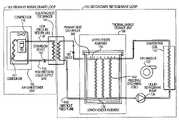
- FIG. 1illustrates an embodiment of a refrigerant-based thermal energy storage and cooling system with secondary refrigerant isolation.
- FIG. 2is a table representing valve status conditions for the refrigerant-based thermal energy storage and cooling system with secondary refrigerant isolation illustrated in FIG. 1 .
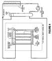
- FIG. 3illustrates a configuration of a refrigerant-based thermal energy storage and cooling system with secondary refrigerant isolation during an ice-make (charging) cycle.
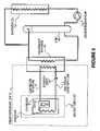
- FIG. 4illustrates a configuration of a refrigerant-based thermal energy storage and cooling system with secondary refrigerant isolation during an ice-melt (cooling) cycle.
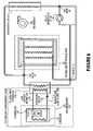
- FIG. 5illustrates a configuration of a refrigerant-based thermal energy storage and cooling system with secondary refrigerant isolation during a direct cooling (bypass) cycle.
- FIG. 6illustrates another embodiment of a refrigerant-based thermal energy storage and cooling system with secondary refrigerant isolation.
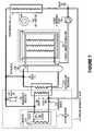
- FIG. 7illustrates another embodiment of a refrigerant-based thermal energy storage and cooling system with secondary refrigerant isolation.
- FIG. 8illustrates an embodiment of a net-zero peak power refrigerant-based thermal energy storage and cooling system with secondary refrigerant isolation.
- FIG. 9illustrates an embodiment of a refrigerant-based thermal energy storage and cooling system with gravity fed secondary refrigerant isolation.
- FIG. 10illustrates an embodiment of a refrigerant-based thermal energy storage and cooling system with gravity fed secondary refrigerant isolation.
- the disclosed embodimentsovercome the disadvantages and limitations of the prior art by providing a refrigerant-based thermal storage system method and device wherein a condensing unit and an ice-tank heat exchanger can be isolated through a second heat exchanger.
- an air conditioner unit 102utilizing a compressor 110 to compress cold, low pressure refrigerant gas to hot, high-pressure gas.
- a condenser 111removes much of the heat in the gas and discharges the heat to the atmosphere.
- the refrigerantcomes out of the condenser as a warm, high-pressure liquid refrigerant delivered through a high-pressure liquid supply line 112 to an isolating heat exchanger 162 through an expansion valve 130 .
- This expansion valve 130may be a conventional thermal expansion valve, a mixed-phase regulator and surge vessel (reservoir) or the like.
- Low-pressure vapor phase and liquid refrigerantis then returned to compressor 110 via low pressure return line 118 completing the primary refrigeration loop.
- the thermal energy storage unit 106comprises an insulated tank 140 that houses the primary heat exchanger 160 surrounded by fluid/ice depending on the current system mode.
- the primary heat exchanger 160further comprises a lower header assembly 156 connected to an upper header assembly 154 with a series of freezing and discharge coils 142 to make a fluid/vapor loop within the insulated tank 140 .
- the upper and lower header assemblies 154 and 156communicate externally of the thermal energy storage unit 106 with inlet and outlet connections.
- An evaporator coil 122is connected within the secondary closed loop refrigeration circuit to the isolating heat exchanger 162 to transmit cooling from the air conditioner unit 102 to a load in one mode (isolated direct cooling) of the system.
- the evaporator coil 122is also connected within the secondary closed loop refrigeration circuit to the primary heat exchanger 160 to receive cooling in another mode (thermal storage cooling).
- Valves 180 - 186are placed in various places within the secondary refrigerant circuits to allow these multi-mode conditions with minimal complexity and plumbing.
- the valve types and configurations presentedare specified for demonstrative purposes and any variety of valve or circuit configurations may be used in conjunction with the disclosed systems and fall within the scope of the invention.
- an accumulator or universal refrigerant management vessel (URMV) 146is in fluid communication with both the thermal energy storage unit 106 and the evaporator coil 122 .
- a liquid refrigerant pump 120is placed on the downstream side of the URMV 146 to pump refrigerant through refrigerant loops to either the evaporator coil 122 or the thermal energy storage unit 106 depending upon the current mode.
- the embodiment illustrated in FIG. 1utilizes the air conditioner unit 102 as the principal cooling source.
- the thermal energy storage unit 106operates using an independent refrigerant (or phase change) loop that transfers the heat between the air conditioner unit 102 and the thermal energy storage unit 106 or a load, represented by the evaporator coil 122 .
- the disclosed embodimentfunctions in two principal modes of operation, ice-make (charging) and ice-melt (cooling) mode.
- compressed high-pressure refrigerantleaves the air conditioner unit 102 through high-pressure liquid supply line 112 and is fed through an expansion valve 130 to cool the primary side of the isolating heat exchanger 162 .
- Warm liquid and vapor phase refrigerantleaves the isolating heat exchanger 162 , returns to the air conditioner unit 102 through the low pressure return line 118 and is fed to the compressor 110 and re-condensed into liquid.
- the heat transfer between the primary loop and the secondary loopis accomplished by the isolating heat exchanger 162 . Fluid leaving the isolating heat exchanger 162 on the secondary side flows to the URMV 146 where the cooled liquid phase refrigerant is accumulated and stored.
- the fluidleaves the URMV 146 and is pumped by a liquid refrigerant pump 120 to the thermal energy storage unit 106 where it enters the primary heat exchanger 160 through the lower header assembly 156 and is then distributed through the freezing coils 142 which act as an evaporator. Cooling is transmitted from the freezing coils 142 to the surrounding fluid 152 that is confined within the insulated tank 140 and eventually produces a block of ice surrounding the freezing coils 142 and storing thermal energy in the process. Warm liquid and vapor phase refrigerant leave the freezing coils 142 through the upper header assembly 154 and exit the thermal energy storage unit 106 returning to the isolating heat exchanger 162 being cooled and condensed once again.
- cool liquid refrigerantleaves URMV 146 and is pumped by a liquid refrigerant pump 120 to the evaporator coil 122 where cooling is transferred to a load.
- Warm liquid and vapor phase refrigerantleave evaporator coil 122 where the liquid phase is returned to the upper portion of the URMV 146 and vapor phase refrigerant is fed to the upper header assembly 154 of the thermal energy storage unit 106 .
- Vapor phase refrigerantproceeds through the discharge coils 142 drawing cooling from the block of ice 152 surrounding the coils, where warm refrigerant is cooled and condensed to cool liquid phase refrigerant.
- This cool liquid phase refrigerantleaves the primary heat exchanger 160 via the lower header assembly 156 and exits the thermal energy storage unit 106 where it is fed into the lower portion of the URMV 146 .
- the two principal modes of operation, ice-make and ice-melt performed with the apparatus of FIG. 1are accomplished with the use of a series of valves 180 - 186 that control the flow of refrigerant through various apparatus which can perform dual functions depending upon the mode.
- the systemisolates a primary refrigerant loop 101 from a secondary refrigerant loop 103 , the system additionally allows the use of different refrigerants to be used within the device.
- one type of highly efficient refrigerant that may have properties that would discourage use within a dwellingsuch as propane
- a more suitable refrigerantsuch as R-22 or R-410A
- FIG. 2is a table representing valve status conditions for the refrigerant-based energy storage and cooling system with secondary refrigerant isolation 200 that is illustrated in FIG. 1 .
- valve # 1 180is in a closed condition
- valve # 2 182allows flow only from the thermal energy storage unit 106 to the isolating heat exchanger 162
- valve # 4 186directs flow from the liquid refrigerant pump 120 to the thermal energy storage unit 106 .
- the evaporator coilis removed from the secondary loop.
- valve # 3 184allows flow only between the refrigerant pump and the thermal energy storage unit 106 .
- valve # 4 186directs flow from the liquid refrigerant pump 120 to the evaporator coil 122 , valve # 1 180 is in an open condition, and valve # 2 182 allows flow only from the evaporator coil 122 to the thermal energy storage unit 106 and the URMV 146 .
- the evaporator coilreceives cooling to transfer to a load. This causes refrigerant to flow through the primary heat exchanger 160 in the opposite direction as in the ice-make mode and allows the primary heat exchanger to act as a condenser.
- Valve # 3 184allows flow only between the thermal energy storage unit 106 and the URMV 146 . With each of the valves 180 - 186 in this ice-melt condition, the system flows as shown in FIG. 4 .
- the isolating heat exchanger 162acts as an evaporator for the air conditioner unit 102 and as a condenser for the thermal energy storage unit 106 .
- the air conditioner unit 102operates at a lower suction temperature, but the loss in efficiency is overpowered by the decrease in cost of the system.
- the refrigerantcan be fed from the thermal energy storage unit 106 to the evaporator coil 122 as shown in FIG. 1 , or the evaporator coil 122 can be utilized as yet another heat exchanger to exchange heat with yet another circuit. This option will entail usage of an additional pump to drive the additional circuit.
- valve # 1 180is in an open condition
- valve # 2 182allows flow from the evaporator coil 122 to the isolating heat exchanger 162 and the URMV 146
- valve # 3 184is closed
- valve # 4 186directs flow from the liquid refrigerant pump 120 to the evaporator coil 122 .
- the thermal energy storage unitis removed from the secondary loop.
- FIG. 3illustrates a configuration of the refrigerant-based energy storage and cooling system with secondary refrigerant isolation of FIG. 1 during an ice-make (charging) cycle.
- compressed high-pressure refrigerantleaves the air conditioner unit 102 through the high-pressure liquid supply line 112 and is fed through an expansion valve 130 to cool the primary side of the isolating heat exchanger 162 .
- Warm liquid and vapor phase refrigerantleave the isolating heat exchanger 162 and returns to the air conditioner unit 102 through the low pressure return line 118 and is fed to the compressor 110 where it is re-condensed into liquid.
- the heat transfer between the primary loop and the secondary loopis accomplished by the isolating heat exchanger 162 .
- Fluid leaving the isolating heat exchanger 162 on the secondary sideflows to the URMV 146 where the cooled liquid phase refrigerant is accumulated.
- the fluidleaves the URMV 146 and is pumped by a liquid refrigerant pump 120 to the thermal energy storage unit 106 where it enters the primary heat exchanger 160 through the lower header assembly 156 and is then distributed through the freezing coils 142 which act as an evaporator. Cooling is transmitted from the freezing coils 142 to the surrounding fluid 152 that is confined within insulated tank 140 and eventually produces a block of ice surrounding the freezing coils 142 and storing thermal energy in the process. Cool liquid and vapor phase refrigerant leave the freezing coils 142 through upper header assembly 154 and exit the thermal energy storage unit 106 and return to the isolating heat exchanger 162 and are cooled and condensed once again.
- FIG. 4illustrates a configuration of the refrigerant-based energy storage and cooling system with secondary refrigerant isolation of FIG. 1 during an ice-melt (cooling) cycle.
- cool liquid refrigerantleaves URMV 146 and is pumped by a liquid refrigerant pump 120 to the evaporator coil 122 where cooling is transferred to a load.
- Warm liquid and vapor phase refrigerantleave evaporator coil 122 where the liquid phase is returned to the upper portion of the URMV 146 and vapor phase refrigerant is fed to the upper header assembly 154 of the thermal energy storage unit 106 .
- Vapor phase refrigerantproceeds through the discharge coils 142 drawing cooling from the block of ice 152 surrounding the coils where it is cooled and condensed to cool liquid phase refrigerant.
- This cool liquid phase refrigerantleaves the primary heat exchanger 160 via the lower header assembly 156 and exits the thermal energy storage unit 106 where it is fed into the lower portion of the URMV 146 .
- FIG. 5illustrates a configuration of the refrigerant-based energy storage and cooling system with secondary refrigerant isolation of FIG. 1 during a direct cooling cycle.
- the thermal energy storage unitis bypassed and cooling is delivered directly form the condenser 111 to the evaporator coil 122 through the isolating heat exchanger 162 .
- the air conditioning unit 102transfers cooling to the primary side of the isolating heat exchanger 162 where cooling is transferred to the secondary side to cool and condense refrigerant in the secondary loop. Cooled liquid refrigerant leaves the isolating heat exchanger 162 and is accumulated in the URMV 146 .
- Cool liquid refrigerantleaves URMV 146 and is pumped by a liquid refrigerant pump 120 to the evaporator coil 122 where cooling is transferred to a load.
- Warm liquid and vapor phase refrigerantleave evaporator coil 122 where the liquid phase is returned to the upper portion of the URMV 146 and vapor phase refrigerant is fed back to the isolating heat exchanger 162 .
- FIG. 6illustrates another embodiment of a refrigerant-based energy storage and cooling system with secondary refrigerant isolation.
- This embodimentfunctions without the need for an accumulator vessel or URMV reducing cost and complexity of the system.
- the embodiment of FIG. 6utilizes the same primary refrigeration loop 101 as shown in FIG. 1 using an air conditioner unit 102 with a compressor 110 and condenser 111 creating high-pressure liquid refrigerant delivered through a high-pressure liquid supply line 112 to an isolating heat exchanger 162 through an expansion valve 130 and low-pressure refrigerant then being returned to compressor 110 via low pressure return line 118 . Cooling is transferred to a secondary refrigeration loop including a thermal energy storage unit 106 through the isolating heat exchanger 162 .
- This thermal energy storage unit 106is structurally comparable to that depicted in FIG. 1 , and acts as an evaporator in the ice-make mode and as a condenser in the ice-melt mode.
- An evaporator coil 122 in conjunction with an air handler 150is connected within the secondary closed loop refrigeration circuit to the isolating heat exchanger 162 to transmit cooling from the primary refrigeration loop 101 and provide isolated, direct cooling in one mode.
- the evaporator coil 122is also connected within the closed secondary loop refrigeration circuit to the thermal energy storage unit 106 to receive cooling in another mode (thermal storage cooling).
- Valves 182 - 186are placed in various places within the secondary refrigerant circuits to allow these multi-mode conditions with minimal complexity and plumbing.
- the valve types and configurations presentedare specified for demonstrative purposes and any variety of valve or circuit configurations may be used in conjunction with the disclosed systems and fall within the scope of the invention.
- a liquid refrigerant pump 120in placed in the secondary refrigeration loop to pump refrigerant to either the evaporator coil 122 or the thermal energy storage unit 106 depending upon the current mode.
- the present embodimentalso functions in two principal modes of operation, ice-make and ice-melt mode.
- ice-make modethe primary refrigerant loop 101 is used to cool the primary side of the isolating heat exchanger 162 that transfers heat to the secondary loop. Fluid leaving the isolating heat exchanger 162 on the secondary side flows to the liquid refrigerant pump 120 where the cooled liquid phase refrigerant is distributed to the thermal energy storage unit 106 acting as an evaporator.
- the liquid refrigerant pump 120is placed below the level of the isolating heat exchanger 162 so that sufficient liquid head above the pump can be maintained. Cooling is transmitted to fluid that is confined within the thermal energy storage unit 106 thus storing thermal energy. Warm liquid and vapor phase refrigerant leaves the thermal energy storage unit 106 and returns to the isolating heat exchanger 162 and is cooled and condensed once again.
- ice-melt modecool liquid refrigerant is drawn from the thermal energy storage unit 106 and is pumped by a liquid refrigerant pump 120 to the evaporator coil 122 where cooling is transferred to a load with the aid of an air handler 150 .
- Warm mixture of liquid and vapor phase refrigerantleaves the evaporator coil 122 where the mixture is returned to the thermal energy storage unit 106 now acting as a condenser.
- Vapor phase refrigerantis cooled and condensed by drawing cooling from the cold fluid or ice.
- two principal modes of operation, ice-make and ice-meltare performed with the use of a series of valves 182 - 186 that control the flow of refrigerant through various apparatus which can perform multiple functions depending upon the mode.
- FIG. 7illustrates another embodiment of a refrigerant-based energy storage and cooling system. This embodiment deviates from the system of FIG. 1 by the location of the accumulator vessel and by the addition of a third mode of operation, a direct cooling mode that bypasses the secondary refrigeration isolation for use when direct cooling from the air conditioner unit 102 may be desirable.
- the embodiment of FIG. 6utilizes the same primary refrigeration loop 101 as shown in previous embodiments but additionally adds a direct cooling loop to provide a non-isolated, direct loop to a cooling load from an air conditioner unit 102 .
- the primary refrigerant loop 101can be used to cool the primary side of the isolating heat exchanger 162 that transfers heat to the secondary loop. Fluid leaving the isolating heat exchanger 162 on the secondary side flows to the URMV 146 and is distributed as liquid refrigerant to either the thermal energy storage unit 106 (ice-make mode), or to the evaporator coil 122 through the liquid refrigerant pump 120 (ice-melt mode), and returned to the upper portion of the URMV 146 .
- coolingis transferred directly to the thermal energy storage unit 106 (acting as an evaporator) where the thermal energy is stored as ice.
- cool liquid refrigerantis drawn from the thermal energy storage unit 106 through the URMV 146 and is pumped to the evaporator coil 122 where cooling is transferred to a load with the aid of an air handler 150 .
- Warm liquid and vapor phase refrigerantleaves the evaporator coil 122 where the liquid phase is returned to the thermal energy storage unit 106 now acting as a condenser.
- Vapor phase refrigerantis accumulated in the upper URMV 146 and drawn into the thermal energy storage unit 106 where it is cooled and condensed with the cold fluid or ice.
- an additional modecan be utilized which has the ability to provide non-isolated, direct cooling from the primary refrigeration loop 101 to the cooling load through the evaporator coil 122 with the aid of an air handler 150 .
- this modethe isolating heat exchanger 162 and the thermal energy storage unit 106 are bypassed to provide this direct cooling.
- the principal modes of operation, ice-make, ice-melt, and direct coolingare performed with the use of a series of valves 180 - 189 that control the flow of refrigerant through various apparatus.
- valve # 5 188 and valve # 6 189close the external loop to the evaporator coil 122 and retain the fluid within the primary refrigeration loop 101 .
- Valves # 1 180 and # 4 186are closed and valve # 2 182 is open.
- valve # 5 188 and valve # 6 189remain in the ice-make condition retaining the fluid within the primary refrigeration loop 101 .
- Valve # 1 180allows flow only from the evaporator coil 122 to the URMV 146 and valve # 4 186 allows flow only from the liquid refrigerant pump 120 to the evaporator coil 122 .
- valve # 5 188 and valve # 6 189prevent flow to the isolating heat exchanger 162 and direct flow to the external loop of the evaporator coil 122 .
- Valve # 1 180allows flow only from evaporator coil 122 to valve # 3 184 that controls a refrigerant receiver 190 , and flow to the air conditioner unit 102 .
- Valve # 4 186allows flow only from the air conditioner unit 102 to the evaporator coil 122 .
- FIG. 8illustrates an embodiment of a net-zero peak power refrigerant-based energy storage and cooling system with secondary refrigerant isolation.
- This embodimentis the system of FIG. 6 with the addition of a photovoltaic generator 170 placed within the apparatus to power the air handler 150 and the liquid refrigerant pump 120 during the ice-melt mode. This allows the system to be used during peak demand times at a net-zero power draw from a utility.
- FIGS. 9 and 10illustrate an embodiment of a refrigerant-based thermal energy storage and cooling system with gravity fed secondary refrigerant isolation.
- the gravity fed systemfunctions without the need for an accumulator vessel or URMV reducing cost and complexity.
- the embodiment of FIGS. 9 and 10also utilize a primary refrigeration loop 101 similarly shown in FIG. 1 .
- Thisincludes an air conditioner unit 102 with a compressor 110 and condenser 111 creating high-pressure liquid refrigerant that is delivered through a high-pressure liquid supply line 112 to an isolating heat exchanger 162 through an expansion valve 130 .
- Low-pressure refrigerantis returned to compressor 110 via low pressure return line 118 .
- Coolingis transferred through the isolating heat exchanger 162 to a thermal energy storage unit 106 within the secondary refrigeration loop 103 .
- This thermal energy storage unit 106is comparable to that depicted in FIG. 1 , and acts as an evaporator in the ice-make mode and as a condenser in the ice-melt mode.
- An evaporator coil 122 in conjunction with an air handler 150is connected within the secondary refrigeration loop 103 to the isolating heat exchanger 162 to transmit cooling from the primary refrigeration loop 101 and provide isolated, direct cooling in one mode.
- the evaporator coil 122is also in communication with the thermal energy storage unit 106 (within the refrigeration loop 103 ) to receive cooling in another mode (thermal storage cooling). Valves may be placed in various places within the secondary refrigerant circuits to allow these multi-mode conditions with minimal complexity and plumbing.
- a liquid refrigerant pump 120is placed in the secondary refrigeration loop to pump refrigerant to the evaporator coil 122 and back to the thermal energy storage unit 106 in another mode.
- the present embodimentmay function in any of three principal modes of operation, ice-make, ice-melt and direct cooling.
- ice-make modethe primary refrigerant loop 102 is used to cool the primary side of the isolating heat exchanger 162 that transfers heat to the secondary refrigerant loop 103 .
- refrigerant on the secondary side isolating heat exchanger 162is cooled and condensed by the primary side the fluid density increases. Heavier liquid on the secondary side drops into a vertical feed tube 192 that feeds the lower header assembly 156 of the primary heat exchanger 160 .
- the gravity feed system of FIGS. 9 and 10are self equalizing when in ice-make mode with respect to the effectiveness of the freezing/discharge coils 142 . For example, if two coils have an equal amount of ice on their surface, and therefore similar thermodynamic forces acting upon them, a similar flow rate of refrigerant through the coils will experienced. On the other hand, if one coil has significantly less ice on it than another, that coil will experience a higher flow rate until the amount of ice on both coils is equal. This occurs because there will be a higher heat flux through the coil with less ice which results in a greater rate of vaporization.
- the thermal energy storage unit 106acts as an evaporator and cooling is transmitted to fluid that is confined within the thermal energy storage unit 106 thus storing thermal energy.
- Warm liquid and vapor phase refrigerantleaves the thermal energy storage unit 106 and returns to the isolating heat exchanger 162 and is cooled and condensed once again.
- the primary refrigerant loop 102can be shut down or disengaged and cool liquid refrigerant is drawn from the thermal energy storage unit 106 and is pumped by a liquid refrigerant pump 120 to the evaporator coil 122 where cooling is transferred to a load with the aid of an air handler 150 .
- the warm mixture of liquid and vapor phase refrigerantleaves the evaporator coil 122 where the mixture is returned to the thermal energy storage unit 106 now acting as a condenser.
- Vapor phase refrigerantis cooled and condensed by drawing cooling from the cold fluid or ice.
- the principal modes of operation, ice-make, ice-melt and direct coolingcan be performed with the use of a series of valves (not shown) that control the flow of refrigerant
- the primary refrigerant loop 102is used to cool the primary side of the isolating heat exchanger 162 and transfer heat to the secondary refrigerant loop 103 .
- Refrigerant on the secondary side isolating heat exchanger 162bypasses the freezing/discharge coils 142 (i.e., by valves not shown) and cool liquid refrigerant is drawn from the secondary side of the isolating heat exchanger 162 and pumped by a liquid refrigerant pump 120 to the evaporator coil 122 where cooling is transferred to a load with the aid of an air handler 150 .
- the warm mixture of liquid and vapor phase refrigerantleaves the evaporator coil 122 where the mixture is returned to the secondary side of the isolating heat exchanger 162 and the refrigerant is cooled and condensed by drawing cooling from the primary side.
- FIGS. 9 and 10specifically depict a gravity feed system
- any of the aforementioned embodiments depicted in FIGS. 1-8are also adaptable for use of a thermosiphon on the isolating heat exchanger with minimal geometric and valve modifications.
- Peak usage conditions for air conditionersgenerally come at times when the outside temperature is very high. At such times, it is difficult for the condenser to reject internal heat to the atmosphere.
- the disclosed systemsincorporate multiple operating modes, the ability to add optional components, and the integration of smart controls that assure energy is stored at maximum efficiency.
- the systemWhen connected to a condensing unit, the system stores refrigeration energy in a first time period, and utilizes the stored energy during a second time period to provide cooling.
- the condensing unitcan bypass the refrigerant energy storage system to provide direct or instantaneous cooling (either isolated or not) during a third time period.
- the detailed embodiments detailed aboveoffer numerous advantages such as minimizing additional components (and therefore, cost).
- the systemsuse very little energy beyond that used by the condensing unit to store the energy, and with the use of a photovoltaic generator, produces a net-zero power draw system during peak demand power rates.
- the refrigerant energy storage designhas been engineered to provide flexibility so that it is practicable for a variety of applications and has further advantage over glycol or other single phase systems due to power consumption. This is because the heat load capacity of 1 lb. of refrigerant during phase change is 80 times the heat load capacity of 1 lb. of water. For example, to maintain the same heat load capacity of water (with a 10 degree F.
- the power requirement for a refrigerant pumpis about 1/20 th of a water pump.
- the systems describedalso eliminate problems with oil return to the compressor and condensing unit because the refrigerant only traverses the evaporator and the expansion valve after leaving the condensing unit.
- the evaporatorcan be designed for optimum oil drainage, keeping the compressor running smoothly.
- the refrigerant chargecan be adjusted optimally for each operating condition, ice making and cooling.
Landscapes
- Engineering & Computer Science (AREA)
- Chemical & Material Sciences (AREA)
- Combustion & Propulsion (AREA)
- Mechanical Engineering (AREA)
- General Engineering & Computer Science (AREA)
- Physics & Mathematics (AREA)
- Thermal Sciences (AREA)
- Life Sciences & Earth Sciences (AREA)
- Sustainable Development (AREA)
- Air Conditioning Control Device (AREA)
- Other Air-Conditioning Systems (AREA)
Abstract
Description
Claims (25)
Priority Applications (1)
| Application Number | Priority Date | Filing Date | Title |
|---|---|---|---|
| US11/284,533US7421846B2 (en) | 2004-08-18 | 2005-11-21 | Thermal energy storage and cooling system with gravity fed secondary refrigerant isolation |
Applications Claiming Priority (3)
| Application Number | Priority Date | Filing Date | Title |
|---|---|---|---|
| US60277404P | 2004-08-18 | 2004-08-18 | |
| US11/208,074US7363772B2 (en) | 2004-08-18 | 2005-08-18 | Thermal energy storage and cooling system with secondary refrigerant isolation |
| US11/284,533US7421846B2 (en) | 2004-08-18 | 2005-11-21 | Thermal energy storage and cooling system with gravity fed secondary refrigerant isolation |
Related Parent Applications (1)
| Application Number | Title | Priority Date | Filing Date |
|---|---|---|---|
| US11/208,074Continuation-In-PartUS7363772B2 (en) | 2004-08-18 | 2005-08-18 | Thermal energy storage and cooling system with secondary refrigerant isolation |
Publications (2)
| Publication Number | Publication Date |
|---|---|
| US20060070385A1 US20060070385A1 (en) | 2006-04-06 |
| US7421846B2true US7421846B2 (en) | 2008-09-09 |
Family
ID=46205789
Family Applications (1)
| Application Number | Title | Priority Date | Filing Date |
|---|---|---|---|
| US11/284,533Active2026-06-28US7421846B2 (en) | 2004-08-18 | 2005-11-21 | Thermal energy storage and cooling system with gravity fed secondary refrigerant isolation |
Country Status (1)
| Country | Link |
|---|---|
| US (1) | US7421846B2 (en) |
Cited By (24)
| Publication number | Priority date | Publication date | Assignee | Title |
|---|---|---|---|---|
| US20080092559A1 (en)* | 2004-07-22 | 2008-04-24 | Era (Environmental Refrigeration Alternatives) Pty Ltd. | Refrigeration System |
| US20090032215A1 (en)* | 2006-10-23 | 2009-02-05 | Ralph Muscatell | Water tank for use with a solar air conditioning system |
| US20090260387A1 (en)* | 2008-04-22 | 2009-10-22 | Defrancesco Gregory L | Aircraft supplemental cooling system |
| US20110011119A1 (en)* | 2009-07-15 | 2011-01-20 | Whirlpool Corporation | High efficiency refrigerator |
| US20110061410A1 (en)* | 2004-08-18 | 2011-03-17 | Ice Energy, Inc. | Thermal energy storage and cooling system with secondary refrigerant isolation |
| US20110100611A1 (en)* | 2008-07-16 | 2011-05-05 | Abb Research Ltd | Thermoelectric energy storage system and method for storing thermoelectric energy |
| US20110204655A1 (en)* | 2010-02-19 | 2011-08-25 | Dynasep Llc | Energy storage systems |
| US8181470B2 (en) | 2008-02-15 | 2012-05-22 | Ice Energy, Inc. | Thermal energy storage and cooling system utilizing multiple refrigerant and cooling loops with a common evaporator coil |
| US20120247148A1 (en)* | 2011-03-28 | 2012-10-04 | Dube Serge | Co2 refrigeration system for ice-playing surface |
| US20120324918A1 (en)* | 2011-06-22 | 2012-12-27 | Whirlpool Corporation | Multi-evaporator refrigerator |
| US8528345B2 (en) | 2003-10-15 | 2013-09-10 | Ice Energy, Inc. | Managed virtual power plant utilizing aggregated storage |
| US9121641B2 (en) | 2012-04-02 | 2015-09-01 | Whirlpool Corporation | Retrofittable thermal storage for air conditioning systems |
| US9188369B2 (en) | 2012-04-02 | 2015-11-17 | Whirlpool Corporation | Fin-coil design for a dual suction air conditioning unit |
| US9203239B2 (en) | 2011-05-26 | 2015-12-01 | Greener-Ice Spv, L.L.C. | System and method for improving grid efficiency utilizing statistical distribution control |
| US9212834B2 (en) | 2011-06-17 | 2015-12-15 | Greener-Ice Spv, L.L.C. | System and method for liquid-suction heat exchange thermal energy storage |
| US20160144764A1 (en)* | 2013-06-18 | 2016-05-26 | Thermo King Corporation | Control method for a hybrid refrigeration system |
| US20160238265A1 (en)* | 2013-10-29 | 2016-08-18 | Arizona Board Of Regents On Behalf Of Arizona State University | Peak load shifting via thermal energy storage using a thermosyphon |
| US9791203B2 (en) | 2006-12-28 | 2017-10-17 | Whirlpool Corporation | Secondary fluid infrastructure within a refrigerator and method thereof |
| US10351042B2 (en) | 2013-06-18 | 2019-07-16 | Thermo King Corporation | Hybrid temperature control system and method |
| US11543216B2 (en) | 2017-03-06 | 2023-01-03 | Rocky Research | Burst mode cooling for directed energy systems |
| US11692779B2 (en)* | 2020-01-23 | 2023-07-04 | Rocky Research | Flexible cooling system with thermal energy storage |
| US12031755B2 (en) | 2021-05-19 | 2024-07-09 | Copeland Lp | Refrigeration system having high-efficiency loop |
| US12259163B2 (en) | 2022-06-01 | 2025-03-25 | Copeland Lp | Climate-control system with thermal storage |
| US12416308B2 (en) | 2022-12-28 | 2025-09-16 | Copeland Lp | Compressor with shutdown assembly |
Families Citing this family (26)
| Publication number | Priority date | Publication date | Assignee | Title |
|---|---|---|---|---|
| KR100455839B1 (en)* | 1999-11-26 | 2004-11-06 | 제이에프이 엔지니어링 가부시키가이샤 | Hydrate thermal storage medium and method for producing thereof, thermal storage apparatus using hydrate thermal storage medium, and hydrate cold thermal transportation medium |
| WO2003102474A1 (en)* | 2002-05-31 | 2003-12-11 | Jfe Engineering Corporation | Hydrate slurry manufacturing device |
| USD538412S1 (en)* | 2005-09-21 | 2007-03-13 | Ice Energy, Inc. | Heat exchanger support |
| US20090133412A1 (en)* | 2007-11-28 | 2009-05-28 | Ice Energy, Inc. | Thermal energy storage and cooling system with multiple cooling loops utilizing a common evaporator coil |
| US8166773B2 (en)* | 2008-10-08 | 2012-05-01 | Venturedyne, Ltd. | Refrigeration capacity banking for thermal cycling |
| US8146375B2 (en)* | 2009-03-10 | 2012-04-03 | Thermo King Corporation | Hydrocooler with thermal storage |
| US20110079025A1 (en)* | 2009-10-02 | 2011-04-07 | Thermo King Corporation | Thermal storage device with ice thickness detection and control methods |
| CN103238035A (en)* | 2010-09-27 | 2013-08-07 | 特米亚热力有限公司 | Heat exchanger arrangement and heat pump system |
| US9557120B2 (en)* | 2012-10-10 | 2017-01-31 | Promethean Power Systems, Inc. | Thermal energy battery with enhanced heat exchange capability and modularity |
| US9562707B2 (en) | 2013-03-14 | 2017-02-07 | Whirlpool Corporation | Refrigerator cooling system having a secondary cooling loop |
| CN104279673A (en)* | 2014-10-17 | 2015-01-14 | 中山市蓝水能源科技发展有限公司 | A telescopic ice storage refrigeration device |
| US20160187014A1 (en)* | 2014-12-29 | 2016-06-30 | Hy-Save Limited | Air Conditioning with Auxiliary Thermal Storage |
| US20160187013A1 (en)* | 2014-12-29 | 2016-06-30 | Hy-Save Limited | Air Conditioning with Thermal Storage |
| US10633785B2 (en) | 2016-08-10 | 2020-04-28 | Whirlpool Corporation | Maintenance free dryer having multiple self-cleaning lint filters |
| US10738411B2 (en) | 2016-10-14 | 2020-08-11 | Whirlpool Corporation | Filterless air-handling system for a heat pump laundry appliance |
| US10519591B2 (en) | 2016-10-14 | 2019-12-31 | Whirlpool Corporation | Combination washing/drying laundry appliance having a heat pump system with reversible condensing and evaporating heat exchangers |
| US10502478B2 (en) | 2016-12-20 | 2019-12-10 | Whirlpool Corporation | Heat rejection system for a condenser of a refrigerant loop within an appliance |
| US10514194B2 (en) | 2017-06-01 | 2019-12-24 | Whirlpool Corporation | Multi-evaporator appliance having a multi-directional valve for delivering refrigerant to the evaporators |
| EP3438579A1 (en) | 2017-07-31 | 2019-02-06 | Whirlpool Corporation | Augmented door bin cooling using an air duct in a dual-evaporator refrigerator configuration |
| US10718082B2 (en) | 2017-08-11 | 2020-07-21 | Whirlpool Corporation | Acoustic heat exchanger treatment for a laundry appliance having a heat pump system |
| US9989271B1 (en) | 2017-08-14 | 2018-06-05 | Calvin Becker | Air conditioning with thermal storage |
| US10429090B2 (en)* | 2017-10-18 | 2019-10-01 | Willis Lewin Usilton | Closed-loop air-to-water air conditioning system |
| US10746440B2 (en)* | 2018-04-12 | 2020-08-18 | Rolls-Royce North American Technologies, Inc. | Thermal management system including two-phased pump loop and thermal energy storage |
| US11530844B2 (en)* | 2020-09-30 | 2022-12-20 | Rolls-Royce North American Technologies Inc. | System for supporting intermittent fast transient heat loads |
| US11744042B2 (en)* | 2020-11-06 | 2023-08-29 | Rolls-Royce North American Technologies Inc. | Thermal management system with dual-use serial thermal energy storage for system size reduction |
| US20240337394A1 (en)* | 2023-04-10 | 2024-10-10 | Ice Bear SPV #1, LLC | Integration of a Thermal Energy Storage Unit With An External HVAC System |
Citations (53)
| Publication number | Priority date | Publication date | Assignee | Title |
|---|---|---|---|---|
| US1969187A (en)* | 1932-02-19 | 1934-08-07 | Clifton E Schutt | Heat balancing system |
| US2512576A (en) | 1947-10-29 | 1950-06-20 | Mojonnier Bros Co Inc | Refrigerating method and apparatus |
| DE1015019B (en) | 1953-06-11 | 1957-09-05 | Ideal Standard | Cooling system for direct evaporation with storage |
| US3156101A (en) | 1963-03-04 | 1964-11-10 | Tranter Mfg Inc | Truck refrigeration system |
| US3746084A (en) | 1970-04-16 | 1973-07-17 | J Ostbo | Heat-exchanger comprising a plurality of helically wound pipe elements |
| US4073306A (en) | 1977-01-27 | 1978-02-14 | Yarway Corporation | Steam trap |
| US4294078A (en) | 1977-04-26 | 1981-10-13 | Calmac Manufacturing Corporation | Method and system for the compact storage of heat and coolness by phase change materials |
| US4403645A (en) | 1978-07-12 | 1983-09-13 | Calmac Manufacturing Corporation | Compact storage of seat and coolness by phase change materials while preventing stratification |
| JPS58217133A (en) | 1982-06-11 | 1983-12-17 | Yazaki Corp | heat pump system |
| US4565069A (en) | 1984-11-05 | 1986-01-21 | Maccracken Calvin D | Method of cyclic air conditioning with cogeneration of ice |
| US4608836A (en) | 1986-02-10 | 1986-09-02 | Calmac Manufacturing Corporation | Multi-mode off-peak storage heat pump |
| US4609036A (en) | 1985-08-07 | 1986-09-02 | The Dow Chemical Company | Bulk heat or cold storage device for thermal energy storage compounds |
| US4619317A (en) | 1983-06-08 | 1986-10-28 | Hoechst Aktiengesellschaft | Heat exchanger |
| US4735064A (en) | 1986-11-17 | 1988-04-05 | Fischer Harry C | Energy storage container and system |
| US4893476A (en) | 1988-08-12 | 1990-01-16 | Phenix Heat Pump Systems, Inc. | Three function heat pump system with one way receiver |
| US4916916A (en) | 1988-11-14 | 1990-04-17 | Fischer Harry C | Energy storage apparatus and method |
| US4940079A (en) | 1988-08-11 | 1990-07-10 | Phenix Heat Pump Systems, Inc. | Optimal control system for refrigeration-coupled thermal energy storage |
| US4964279A (en) | 1989-06-07 | 1990-10-23 | Baltimore Aircoil Company | Cooling system with supplemental thermal storage |
| US5005368A (en) | 1990-02-07 | 1991-04-09 | Calmac Manufacturing Corporation | Coolness storage air conditioner appliance |
| US5109920A (en) | 1987-05-25 | 1992-05-05 | Ice-Cel Pty. Limited | Method of manufacturing heat exchangers |
| US5211029A (en) | 1991-05-28 | 1993-05-18 | Lennox Industries Inc. | Combined multi-modal air conditioning apparatus and negative energy storage system |
| US5237832A (en) | 1992-06-11 | 1993-08-24 | Alston Gerald A | Combined marine refrigerating and air conditioning system using thermal storage |
| US5255526A (en) | 1992-03-18 | 1993-10-26 | Fischer Harry C | Multi-mode air conditioning unit with energy storage system |
| US5366153A (en) | 1993-01-06 | 1994-11-22 | Consolidated Natural Gas Service Company, Inc. | Heat pump system with refrigerant isolation and heat storage |
| US5383339A (en) | 1992-12-10 | 1995-01-24 | Baltimore Aircoil Company, Inc. | Supplemental cooling system for coupling to refrigerant-cooled apparatus |
| EP0641978A1 (en) | 1993-09-04 | 1995-03-08 | Star Refrigeration Ltd. | Improvements in and relating to refrigeration method and apparatus |
| US5423378A (en) | 1994-03-07 | 1995-06-13 | Dunham-Bush | Heat exchanger element and heat exchanger using same |
| US5467812A (en) | 1994-08-19 | 1995-11-21 | Lennox Industries Inc. | Air conditioning system with thermal energy storage and load leveling capacity |
| JPH0814628A (en) | 1994-06-29 | 1996-01-19 | Sanyo Electric Co Ltd | Air conditioner |
| JPH08226682A (en) | 1995-02-17 | 1996-09-03 | Chubu Electric Power Co Inc | Ice heat storage type air conditioner |
| US5598720A (en) | 1995-08-02 | 1997-02-04 | Calmac Manufacturing Corporation | Air bubble heat transfer enhancement system coolness storage apparatus |
| US5647225A (en) | 1995-06-14 | 1997-07-15 | Fischer; Harry C. | Multi-mode high efficiency air conditioning system |
| US5678626A (en) | 1994-08-19 | 1997-10-21 | Lennox Industries Inc. | Air conditioning system with thermal energy storage and load leveling capacity |
| US5682752A (en) | 1995-07-11 | 1997-11-04 | Lennox Industries Inc. | Refrigerant management control and method for a thermal energy storage system |
| US5720178A (en) | 1996-07-15 | 1998-02-24 | Calmac Manufacturing Corporation | Refrigeration system with isolation of vapor component from compressor |
| JPH10339483A (en) | 1997-06-06 | 1998-12-22 | Daikin Ind Ltd | Thermal storage device |
| DE29823175U1 (en) | 1998-12-29 | 1999-06-10 | Dietzsch, Michael, Prof. Dr.-Ing., 09126 Chemnitz | Climate room |
| US6112543A (en) | 1998-08-27 | 2000-09-05 | Behr Gmbh & Co. | Device for cooling an interior compartment of a motor vehicle |
| JP2000249420A (en) | 1999-03-01 | 2000-09-14 | Daikin Ind Ltd | Ice storage device and ice storage type refrigeration device |
| JP2000266368A (en) | 1999-03-16 | 2000-09-29 | Hitachi Air Conditioning System Co Ltd | Air conditioning system |
| US6158499A (en) | 1998-12-23 | 2000-12-12 | Fafco, Inc. | Method and apparatus for thermal energy storage |
| DE19831127A1 (en) | 1998-07-11 | 2001-03-15 | Baelz Gmbh Helmut | Prediction-controlled air conditioning system has communications device connected to regulator for specifying demand value, accepting future weather conditions information signals |
| US6247522B1 (en) | 1998-11-04 | 2001-06-19 | Baltimore Aircoil Company, Inc. | Heat exchange members for thermal storage apparatus |
| US6250098B1 (en) | 2000-02-08 | 2001-06-26 | Chung-Ping Huang | Support frame for an ice-storing tank for an air conditioner with an ice-storing mode |
| US6260376B1 (en) | 1998-12-23 | 2001-07-17 | Valeo Klimasysteme Gmbh | Air conditioning installation for a motor vehicle with a cold reservoir |
| JP2001296068A (en) | 2000-04-14 | 2001-10-26 | Daikin Ind Ltd | Thermal storage refrigeration system |
| DE10057834A1 (en) | 2000-11-22 | 2002-06-06 | Ingo Brauns | Method for controlling energy consumption of a heating and/or cooling system determines a control value using an energy consumption value normalized to the difference between the internal temperature and external temperature |
| US6474089B1 (en) | 2001-10-01 | 2002-11-05 | Sih-Li Chen | Natural air-conditioning system for a car |
| US20020162342A1 (en) | 2001-05-01 | 2002-11-07 | Kuo-Liang Weng | Method for controlling air conditioner/heater by thermal storage |
| EP1441183A1 (en) | 2003-01-27 | 2004-07-28 | Tecnocasa S.R.L. | Electronic hydraulic device for heat pumps |
| US20040221589A1 (en) | 2003-05-09 | 2004-11-11 | Serge Dube | Energy storage with refrigeration systems and method |
| WO2005001345A1 (en) | 2003-06-25 | 2005-01-06 | Star Refrigeration Limited | Improved cooling system |
| USD501490S1 (en) | 2003-12-16 | 2005-02-01 | Ice Energy, Llc | Thermal energy storage module |
Family Cites Families (1)
| Publication number | Priority date | Publication date | Assignee | Title |
|---|---|---|---|---|
| TWI220163B (en)* | 2003-04-24 | 2004-08-11 | Ind Tech Res Inst | Manufacturing method of high-conductivity nanometer thin-film probe card |
- 2005
- 2005-11-21USUS11/284,533patent/US7421846B2/enactiveActive
Patent Citations (53)
| Publication number | Priority date | Publication date | Assignee | Title |
|---|---|---|---|---|
| US1969187A (en)* | 1932-02-19 | 1934-08-07 | Clifton E Schutt | Heat balancing system |
| US2512576A (en) | 1947-10-29 | 1950-06-20 | Mojonnier Bros Co Inc | Refrigerating method and apparatus |
| DE1015019B (en) | 1953-06-11 | 1957-09-05 | Ideal Standard | Cooling system for direct evaporation with storage |
| US3156101A (en) | 1963-03-04 | 1964-11-10 | Tranter Mfg Inc | Truck refrigeration system |
| US3746084A (en) | 1970-04-16 | 1973-07-17 | J Ostbo | Heat-exchanger comprising a plurality of helically wound pipe elements |
| US4073306A (en) | 1977-01-27 | 1978-02-14 | Yarway Corporation | Steam trap |
| US4294078A (en) | 1977-04-26 | 1981-10-13 | Calmac Manufacturing Corporation | Method and system for the compact storage of heat and coolness by phase change materials |
| US4403645A (en) | 1978-07-12 | 1983-09-13 | Calmac Manufacturing Corporation | Compact storage of seat and coolness by phase change materials while preventing stratification |
| JPS58217133A (en) | 1982-06-11 | 1983-12-17 | Yazaki Corp | heat pump system |
| US4619317A (en) | 1983-06-08 | 1986-10-28 | Hoechst Aktiengesellschaft | Heat exchanger |
| US4565069A (en) | 1984-11-05 | 1986-01-21 | Maccracken Calvin D | Method of cyclic air conditioning with cogeneration of ice |
| US4609036A (en) | 1985-08-07 | 1986-09-02 | The Dow Chemical Company | Bulk heat or cold storage device for thermal energy storage compounds |
| US4608836A (en) | 1986-02-10 | 1986-09-02 | Calmac Manufacturing Corporation | Multi-mode off-peak storage heat pump |
| US4735064A (en) | 1986-11-17 | 1988-04-05 | Fischer Harry C | Energy storage container and system |
| US5109920A (en) | 1987-05-25 | 1992-05-05 | Ice-Cel Pty. Limited | Method of manufacturing heat exchangers |
| US4940079A (en) | 1988-08-11 | 1990-07-10 | Phenix Heat Pump Systems, Inc. | Optimal control system for refrigeration-coupled thermal energy storage |
| US4893476A (en) | 1988-08-12 | 1990-01-16 | Phenix Heat Pump Systems, Inc. | Three function heat pump system with one way receiver |
| US4916916A (en) | 1988-11-14 | 1990-04-17 | Fischer Harry C | Energy storage apparatus and method |
| US4964279A (en) | 1989-06-07 | 1990-10-23 | Baltimore Aircoil Company | Cooling system with supplemental thermal storage |
| US5005368A (en) | 1990-02-07 | 1991-04-09 | Calmac Manufacturing Corporation | Coolness storage air conditioner appliance |
| US5211029A (en) | 1991-05-28 | 1993-05-18 | Lennox Industries Inc. | Combined multi-modal air conditioning apparatus and negative energy storage system |
| US5255526A (en) | 1992-03-18 | 1993-10-26 | Fischer Harry C | Multi-mode air conditioning unit with energy storage system |
| US5237832A (en) | 1992-06-11 | 1993-08-24 | Alston Gerald A | Combined marine refrigerating and air conditioning system using thermal storage |
| US5383339A (en) | 1992-12-10 | 1995-01-24 | Baltimore Aircoil Company, Inc. | Supplemental cooling system for coupling to refrigerant-cooled apparatus |
| US5366153A (en) | 1993-01-06 | 1994-11-22 | Consolidated Natural Gas Service Company, Inc. | Heat pump system with refrigerant isolation and heat storage |
| EP0641978A1 (en) | 1993-09-04 | 1995-03-08 | Star Refrigeration Ltd. | Improvements in and relating to refrigeration method and apparatus |
| US5423378A (en) | 1994-03-07 | 1995-06-13 | Dunham-Bush | Heat exchanger element and heat exchanger using same |
| JPH0814628A (en) | 1994-06-29 | 1996-01-19 | Sanyo Electric Co Ltd | Air conditioner |
| US5678626A (en) | 1994-08-19 | 1997-10-21 | Lennox Industries Inc. | Air conditioning system with thermal energy storage and load leveling capacity |
| US5467812A (en) | 1994-08-19 | 1995-11-21 | Lennox Industries Inc. | Air conditioning system with thermal energy storage and load leveling capacity |
| JPH08226682A (en) | 1995-02-17 | 1996-09-03 | Chubu Electric Power Co Inc | Ice heat storage type air conditioner |
| US5647225A (en) | 1995-06-14 | 1997-07-15 | Fischer; Harry C. | Multi-mode high efficiency air conditioning system |
| US5682752A (en) | 1995-07-11 | 1997-11-04 | Lennox Industries Inc. | Refrigerant management control and method for a thermal energy storage system |
| US5598720A (en) | 1995-08-02 | 1997-02-04 | Calmac Manufacturing Corporation | Air bubble heat transfer enhancement system coolness storage apparatus |
| US5720178A (en) | 1996-07-15 | 1998-02-24 | Calmac Manufacturing Corporation | Refrigeration system with isolation of vapor component from compressor |
| JPH10339483A (en) | 1997-06-06 | 1998-12-22 | Daikin Ind Ltd | Thermal storage device |
| DE19831127A1 (en) | 1998-07-11 | 2001-03-15 | Baelz Gmbh Helmut | Prediction-controlled air conditioning system has communications device connected to regulator for specifying demand value, accepting future weather conditions information signals |
| US6112543A (en) | 1998-08-27 | 2000-09-05 | Behr Gmbh & Co. | Device for cooling an interior compartment of a motor vehicle |
| US6247522B1 (en) | 1998-11-04 | 2001-06-19 | Baltimore Aircoil Company, Inc. | Heat exchange members for thermal storage apparatus |
| US6260376B1 (en) | 1998-12-23 | 2001-07-17 | Valeo Klimasysteme Gmbh | Air conditioning installation for a motor vehicle with a cold reservoir |
| US6158499A (en) | 1998-12-23 | 2000-12-12 | Fafco, Inc. | Method and apparatus for thermal energy storage |
| DE29823175U1 (en) | 1998-12-29 | 1999-06-10 | Dietzsch, Michael, Prof. Dr.-Ing., 09126 Chemnitz | Climate room |
| JP2000249420A (en) | 1999-03-01 | 2000-09-14 | Daikin Ind Ltd | Ice storage device and ice storage type refrigeration device |
| JP2000266368A (en) | 1999-03-16 | 2000-09-29 | Hitachi Air Conditioning System Co Ltd | Air conditioning system |
| US6250098B1 (en) | 2000-02-08 | 2001-06-26 | Chung-Ping Huang | Support frame for an ice-storing tank for an air conditioner with an ice-storing mode |
| JP2001296068A (en) | 2000-04-14 | 2001-10-26 | Daikin Ind Ltd | Thermal storage refrigeration system |
| DE10057834A1 (en) | 2000-11-22 | 2002-06-06 | Ingo Brauns | Method for controlling energy consumption of a heating and/or cooling system determines a control value using an energy consumption value normalized to the difference between the internal temperature and external temperature |
| US20020162342A1 (en) | 2001-05-01 | 2002-11-07 | Kuo-Liang Weng | Method for controlling air conditioner/heater by thermal storage |
| US6474089B1 (en) | 2001-10-01 | 2002-11-05 | Sih-Li Chen | Natural air-conditioning system for a car |
| EP1441183A1 (en) | 2003-01-27 | 2004-07-28 | Tecnocasa S.R.L. | Electronic hydraulic device for heat pumps |
| US20040221589A1 (en) | 2003-05-09 | 2004-11-11 | Serge Dube | Energy storage with refrigeration systems and method |
| WO2005001345A1 (en) | 2003-06-25 | 2005-01-06 | Star Refrigeration Limited | Improved cooling system |
| USD501490S1 (en) | 2003-12-16 | 2005-02-01 | Ice Energy, Llc | Thermal energy storage module |
Non-Patent Citations (4)
| Title |
|---|
| U.S. Appl. No. 10/967,028, filed Oct. 15, 2004, Michael W. McRell. |
| U.S. Appl. No. 10/967,114, filed Oct. 15, 2004, Ramachandran Narayanamurthy et al. |
| U.S. Appl. No. 11/112,861, filed Apr. 22, 2005, Ramachandran Narayanamurthy et al. |
| U.S. Appl. No. 11/138,762, filed May 25, 2005, Ramachandran Narayanamurthy. |
Cited By (33)
| Publication number | Priority date | Publication date | Assignee | Title |
|---|---|---|---|---|
| US8528345B2 (en) | 2003-10-15 | 2013-09-10 | Ice Energy, Inc. | Managed virtual power plant utilizing aggregated storage |
| US7600392B2 (en)* | 2004-07-22 | 2009-10-13 | ERA (Environmental Refigeration Alternatives) Pty Ltd | Refrigeration system |
| US20080092559A1 (en)* | 2004-07-22 | 2008-04-24 | Era (Environmental Refrigeration Alternatives) Pty Ltd. | Refrigeration System |
| US8505313B2 (en) | 2004-08-18 | 2013-08-13 | Ice Energy Holdings, Inc. | Thermal energy storage and cooling system with secondary refrigerant isolation |
| US8707723B2 (en) | 2004-08-18 | 2014-04-29 | Ice Energy Holdings, Inc. | Multiple refrigerant thermal energy storage and cooling system with secondary refrigerant isolation |
| US20110061410A1 (en)* | 2004-08-18 | 2011-03-17 | Ice Energy, Inc. | Thermal energy storage and cooling system with secondary refrigerant isolation |
| US20090032215A1 (en)* | 2006-10-23 | 2009-02-05 | Ralph Muscatell | Water tank for use with a solar air conditioning system |
| US9791203B2 (en) | 2006-12-28 | 2017-10-17 | Whirlpool Corporation | Secondary fluid infrastructure within a refrigerator and method thereof |
| US8181470B2 (en) | 2008-02-15 | 2012-05-22 | Ice Energy, Inc. | Thermal energy storage and cooling system utilizing multiple refrigerant and cooling loops with a common evaporator coil |
| US7975499B2 (en)* | 2008-04-22 | 2011-07-12 | Hamilton Sundstrand Corporation | Aircraft supplemental cooling system |
| US20090260387A1 (en)* | 2008-04-22 | 2009-10-22 | Defrancesco Gregory L | Aircraft supplemental cooling system |
| US20110100611A1 (en)* | 2008-07-16 | 2011-05-05 | Abb Research Ltd | Thermoelectric energy storage system and method for storing thermoelectric energy |
| US9897364B2 (en) | 2009-07-15 | 2018-02-20 | Whirlpool Corporation | High efficiency refrigerator |
| US8511109B2 (en) | 2009-07-15 | 2013-08-20 | Whirlpool Corporation | High efficiency refrigerator |
| US20110011119A1 (en)* | 2009-07-15 | 2011-01-20 | Whirlpool Corporation | High efficiency refrigerator |
| US20110204655A1 (en)* | 2010-02-19 | 2011-08-25 | Dynasep Llc | Energy storage systems |
| US8484986B2 (en) | 2010-02-19 | 2013-07-16 | Phase Change Storage Llc | Energy storage systems |
| US20120247148A1 (en)* | 2011-03-28 | 2012-10-04 | Dube Serge | Co2 refrigeration system for ice-playing surface |
| US9203239B2 (en) | 2011-05-26 | 2015-12-01 | Greener-Ice Spv, L.L.C. | System and method for improving grid efficiency utilizing statistical distribution control |
| US9212834B2 (en) | 2011-06-17 | 2015-12-15 | Greener-Ice Spv, L.L.C. | System and method for liquid-suction heat exchange thermal energy storage |
| US20120324918A1 (en)* | 2011-06-22 | 2012-12-27 | Whirlpool Corporation | Multi-evaporator refrigerator |
| US9121641B2 (en) | 2012-04-02 | 2015-09-01 | Whirlpool Corporation | Retrofittable thermal storage for air conditioning systems |
| US9188369B2 (en) | 2012-04-02 | 2015-11-17 | Whirlpool Corporation | Fin-coil design for a dual suction air conditioning unit |
| US9863674B2 (en) | 2012-04-02 | 2018-01-09 | Whirlpool Corporation | Fin-coil design for dual suction air conditioning unit |
| US9688181B2 (en)* | 2013-06-18 | 2017-06-27 | Thermo King Corporation | Control method for a hybrid refrigeration system |
| US20160144764A1 (en)* | 2013-06-18 | 2016-05-26 | Thermo King Corporation | Control method for a hybrid refrigeration system |
| US10351042B2 (en) | 2013-06-18 | 2019-07-16 | Thermo King Corporation | Hybrid temperature control system and method |
| US20160238265A1 (en)* | 2013-10-29 | 2016-08-18 | Arizona Board Of Regents On Behalf Of Arizona State University | Peak load shifting via thermal energy storage using a thermosyphon |
| US11543216B2 (en) | 2017-03-06 | 2023-01-03 | Rocky Research | Burst mode cooling for directed energy systems |
| US11692779B2 (en)* | 2020-01-23 | 2023-07-04 | Rocky Research | Flexible cooling system with thermal energy storage |
| US12031755B2 (en) | 2021-05-19 | 2024-07-09 | Copeland Lp | Refrigeration system having high-efficiency loop |
| US12259163B2 (en) | 2022-06-01 | 2025-03-25 | Copeland Lp | Climate-control system with thermal storage |
| US12416308B2 (en) | 2022-12-28 | 2025-09-16 | Copeland Lp | Compressor with shutdown assembly |
Also Published As
| Publication number | Publication date |
|---|---|
| US20060070385A1 (en) | 2006-04-06 |
Similar Documents
| Publication | Publication Date | Title |
|---|---|---|
| US7421846B2 (en) | Thermal energy storage and cooling system with gravity fed secondary refrigerant isolation | |
| US7363772B2 (en) | Thermal energy storage and cooling system with secondary refrigerant isolation | |
| US8181470B2 (en) | Thermal energy storage and cooling system utilizing multiple refrigerant and cooling loops with a common evaporator coil | |
| US20080034760A1 (en) | Thermal energy storage and cooling system with isolated external melt cooling | |
| US20090293507A1 (en) | Thermal energy storage and cooling system with isolated evaporator coil | |
| US20090133412A1 (en) | Thermal energy storage and cooling system with multiple cooling loops utilizing a common evaporator coil | |
| US7124594B2 (en) | High efficiency refrigerant based energy storage and cooling system | |
| US9212834B2 (en) | System and method for liquid-suction heat exchange thermal energy storage | |
| US7827807B2 (en) | Refrigerant-based thermal energy storage and cooling system with enhanced heat exchange capability | |
| AU2005277327B2 (en) | Thermal energy storage and cooling system with secondary refrigerant isolation | |
| US20240337394A1 (en) | Integration of a Thermal Energy Storage Unit With An External HVAC System |
Legal Events
| Date | Code | Title | Description |
|---|---|---|---|
| AS | Assignment | Owner name:ICE ENERGY, INC., COLORADO Free format text:ASSIGNMENT OF ASSIGNORS INTEREST;ASSIGNORS:NARAYANAMURTHY, RAMACHANDRAN;WILLIS, ROBERT R., JR.;REEL/FRAME:017264/0375 Effective date:20051118 | |
| STCF | Information on status: patent grant | Free format text:PATENTED CASE | |
| FPAY | Fee payment | Year of fee payment:4 | |
| AS | Assignment | Owner name:ICE ENERGY HOLDINGS, INC., CALIFORNIA Free format text:ASSIGNMENT OF ASSIGNORS INTEREST;ASSIGNOR:ICE ENERGY, INC.;REEL/FRAME:028544/0119 Effective date:20120523 | |
| FPAY | Fee payment | Year of fee payment:8 | |
| FEPP | Fee payment procedure | Free format text:MAINTENANCE FEE REMINDER MAILED (ORIGINAL EVENT CODE: REM.); ENTITY STATUS OF PATENT OWNER: SMALL ENTITY | |
| FEPP | Fee payment procedure | Free format text:7.5 YR SURCHARGE - LATE PMT W/IN 6 MO, LARGE ENTITY (ORIGINAL EVENT CODE: M1555); ENTITY STATUS OF PATENT OWNER: SMALL ENTITY Free format text:11.5 YR SURCHARGE- LATE PMT W/IN 6 MO, SMALL ENTITY (ORIGINAL EVENT CODE: M2556); ENTITY STATUS OF PATENT OWNER: SMALL ENTITY | |
| MAFP | Maintenance fee payment | Free format text:PAYMENT OF MAINTENANCE FEE, 8TH YEAR, LARGE ENTITY (ORIGINAL EVENT CODE: M1552); ENTITY STATUS OF PATENT OWNER: SMALL ENTITY Year of fee payment:8 Free format text:PAYMENT OF MAINTENANCE FEE, 12TH YR, SMALL ENTITY (ORIGINAL EVENT CODE: M2553); ENTITY STATUS OF PATENT OWNER: SMALL ENTITY Year of fee payment:12 | |
| REFU | Refund | Free format text:REFUND - 7.5 YR SURCHARGE - LATE PMT W/IN 6 MO, LARGE ENTITY (ORIGINAL EVENT CODE: R1555); ENTITY STATUS OF PATENT OWNER: SMALL ENTITY Free format text:REFUND - PAYMENT OF MAINTENANCE FEE, 8TH YEAR, LARGE ENTITY (ORIGINAL EVENT CODE: R1552); ENTITY STATUS OF PATENT OWNER: SMALL ENTITY | |
| AS | Assignment | Owner name:ICE BEAR SPV #1, NEW YORK Free format text:ASSIGNMENT OF ASSIGNORS INTEREST;ASSIGNOR:ICE ENERGY HOLDINGS, INC.;REEL/FRAME:062378/0070 Effective date:20230110 Owner name:ACP THULE INVESTMENTS, LLC, NEW YORK Free format text:ASSIGNMENT OF ASSIGNORS INTEREST;ASSIGNOR:ICE ENERGY HOLDINGS, INC.;REEL/FRAME:062378/0070 Effective date:20230110 |