US7421509B2 - Enforcing quality of service in a storage network - Google Patents
Enforcing quality of service in a storage networkDownload PDFInfo
- Publication number
- US7421509B2 US7421509B2US10/051,339US5133902AUS7421509B2US 7421509 B2US7421509 B2US 7421509B2US 5133902 AUS5133902 AUS 5133902AUS 7421509 B2US7421509 B2US 7421509B2
- Authority
- US
- United States
- Prior art keywords
- initiator
- storage
- switch
- bandwidth
- requests
- Prior art date
- Legal status (The legal status is an assumption and is not a legal conclusion. Google has not performed a legal analysis and makes no representation as to the accuracy of the status listed.)
- Expired - Lifetime, expires
Links
Images


Classifications
- H—ELECTRICITY
- H04—ELECTRIC COMMUNICATION TECHNIQUE
- H04L—TRANSMISSION OF DIGITAL INFORMATION, e.g. TELEGRAPHIC COMMUNICATION
- H04L67/00—Network arrangements or protocols for supporting network services or applications
- H04L67/01—Protocols
- H04L67/10—Protocols in which an application is distributed across nodes in the network
- H04L67/1097—Protocols in which an application is distributed across nodes in the network for distributed storage of data in networks, e.g. transport arrangements for network file system [NFS], storage area networks [SAN] or network attached storage [NAS]
- H—ELECTRICITY
- H04—ELECTRIC COMMUNICATION TECHNIQUE
- H04L—TRANSMISSION OF DIGITAL INFORMATION, e.g. TELEGRAPHIC COMMUNICATION
- H04L67/00—Network arrangements or protocols for supporting network services or applications
- H04L67/01—Protocols
- H04L67/10—Protocols in which an application is distributed across nodes in the network
- H04L67/1001—Protocols in which an application is distributed across nodes in the network for accessing one among a plurality of replicated servers
- H04L67/1004—Server selection for load balancing
- H04L67/1008—Server selection for load balancing based on parameters of servers, e.g. available memory or workload
- H—ELECTRICITY
- H04—ELECTRIC COMMUNICATION TECHNIQUE
- H04L—TRANSMISSION OF DIGITAL INFORMATION, e.g. TELEGRAPHIC COMMUNICATION
- H04L67/00—Network arrangements or protocols for supporting network services or applications
- H04L67/01—Protocols
- H04L67/10—Protocols in which an application is distributed across nodes in the network
- H04L67/1001—Protocols in which an application is distributed across nodes in the network for accessing one among a plurality of replicated servers
- H04L67/1004—Server selection for load balancing
- H04L67/101—Server selection for load balancing based on network conditions
- H—ELECTRICITY
- H04—ELECTRIC COMMUNICATION TECHNIQUE
- H04L—TRANSMISSION OF DIGITAL INFORMATION, e.g. TELEGRAPHIC COMMUNICATION
- H04L67/00—Network arrangements or protocols for supporting network services or applications
- H04L67/50—Network services
- H04L67/60—Scheduling or organising the servicing of application requests, e.g. requests for application data transmissions using the analysis and optimisation of the required network resources
- H04L67/61—Scheduling or organising the servicing of application requests, e.g. requests for application data transmissions using the analysis and optimisation of the required network resources taking into account QoS or priority requirements
- H—ELECTRICITY
- H04—ELECTRIC COMMUNICATION TECHNIQUE
- H04L—TRANSMISSION OF DIGITAL INFORMATION, e.g. TELEGRAPHIC COMMUNICATION
- H04L67/00—Network arrangements or protocols for supporting network services or applications
- H04L67/01—Protocols
- H04L67/10—Protocols in which an application is distributed across nodes in the network
- H04L67/1001—Protocols in which an application is distributed across nodes in the network for accessing one among a plurality of replicated servers
Definitions
- the inventiongenerally relates to storage area networks.
- a SANis defined by the Storage Networking Industry Association (SNIA) as a network whose primary purpose is the transfer of data between computer systems and storage elements and among storage elements.
- SNIAStorage Networking Industry Association
- the SANforms essentially an independent network that does not tend to have the same bandwidth limitations as its direct-connect SCSI and NAS counterparts and also provides increased configurability and scalability.
- storage devicese.g., tape drives and RAID arrays
- serversare generally interconnected via various switches and appliances.
- the connections to the switches and appliancesare usually Fibre Channel.
- Fibre ChannelThis structure generally allows for any server on the SAN to communicate with any storage device and vice versa. It also provides alternative paths from server to storage device. In other words, if a particular server is slow or completely unavailable, another server on the SAN can provide access to the storage device.
- a SANalso makes it possible to mirror data, making multiple copies available and thus creating more reliability in the availability of data. When more storage is needed, additional storage devices can be added to the SAN without the need to be connected to a specific server; rather, the new devices can simply be added to the storage network and can be accessed from any point.
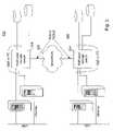
- FIG. 1An example of a SAN is shown in the system 100 illustrated in the functional block diagram of FIG. 1 .
- servers 102there are one or more servers 102 .
- Three servers 102are shown for exemplary purposes only.
- Servers 102are connected through an Ethernet connection to a LAN 106 and/or to a router 108 and then to a WAN 110 , such as the Internet.
- each server 102is connected through a Fibre Channel connection to each of a plurality of Fibre Channel switches 112 sometimes referred to as the “fabric” of the SAN.
- Two switches 112are shown for exemplary purposes only.
- Each switch 112is in turn connected to each of a plurality of SAN appliances 114 .
- Two appliances 114are shown for exemplary purposes only.
- Each applianceis also coupled to each of a plurality of storage devices 116 , such as tape drives, optical drives, or RAID arrays.
- each switch 112 and appliance 114is coupled to a gateway 118 , which in turn is coupled to router 108 , which ultimately connects to a Wide Area Network (WAN) 118 , such as the Internet.
- FIG. 1shows one example of a possible configuration of a SAN 119 , which includes switches 112 , appliances 114 , storage devices 116 , and gateways 118 . Still other configurations are possible. For instance, one appliance may be connected to fewer than all the switches.
- Appliances 114perform the storage management of the SAN. When the appliance 114 receives data, it stores the data in a memory in the appliance. Then, with a processor (also in the appliance), analyzes and operates on the data in order to forward the data to the correct storage device(s). This store-and-forward process typically slows down data access.
- appliancesdo perform some switching, because there may be a large number of servers (many more than three), and because each appliance has few ports (usually only two or four), switches 112 are needed to connect the many servers to the few appliances. Nevertheless, switches 112 have little built-in intelligence and merely forward data to a selected appliance 114 .
- One limitation of appliancesis the fact that many appliances often have a limited or set number of ports. Adding ports to an appliance, although possible, is typically very expensive. Every one or two ports are supported by an expensive CPU or server card. So generally to add ports, entire file cards (which perform virtualization and store-and-forward functions) must be added to the device, which is usually very costly. In the alternative, appliances are simply added to the SAN, but again, this tends to be very costly.
- SANsusually in the appliances 114 , generally perform a function known as “virtualization.”
- Virtualizationoccurs when space on one or more physical storage devices is allocated to a particular user, but the physical location of that space remains unknown to the user. For instance, a user may access its company's “engineering storage space,” ENG:, accessing and “seeing” the virtual space ENG: as he or she would access or “see” an attached disk drive. Nonetheless, the ENG: space may be divided over several physical storage devices or even fragmented on a single storage device.
- a serverrequests a virtual device (e.g., ENG:) and block number, the appliance must determine the device(s) that physically correlate to the virtual device requested and direct the data accordingly.
- SANswere introduced several years ago, interoperability problems, lack of available skills, and high implementation costs remain major obstacles to widespread use. For instance, SANs as they currently exist have high deployment costs and high management costs.
- each switch, appliance, and gatewaytypically come from different vendors, creating a lack of management standards that has resulted in the proliferation of vendor-specific management tools. As a result, to deploy a SAN, equipment must be purchased from multiple vendors. And, as shown in FIG. 1 , each switch, appliance, gateway, storage device, server, and router will have its own management, shown as management stations 120 .
- independent physical management stationsare shown, it is to be understood that independent management is frequently in the form of independent, vendor-specific software on a single computer but which software does not communicate with one another. As a result, there is no centralized management of the SAN and its management costs are high given that there are usually multiple management stations that frequently require many people to manage.
- provisioningof (or “creating”) virtual targets for SANs has become burdensome.
- a human administratorWhen a new virtual target needs to be created, a human administrator must first determine the application requirements for the data, such as performance, capacity required initially plus that required for potential growth, data availability, and data protection. More specifically, the administrator must allocate all or part of one or more physical devices to the virtual target and configure those devices to produce the best performance as well as access control for data security. The administrator must further assure the routes through the storage network have the level of availability required and may have to install alternate pathing if high availability is required so that if one path goes down another path to the target is available. Finally, the administrator must test the environment to verify the functionality before making the virtual target accessible. Overall, it may take several days or even weeks to create such a virtual target—a time period that is often unacceptable to users of the SAN.
- a system in accordance with an embodiment of the inventionautomatically discovers storage resources in communication with a switch and obtains information about the characteristics of those resources. Once the characteristics are known, in one embodiment, the device is classified according to a predefined policy and then placed in a storage pool.
- a virtual targetcan be provisioned.
- the virtual targetis placed in a user domain.
- An initiator connectionis also provisioned in one embodiment.
- the virtual target, the initiator connection, and the user domainall serve in one embodiment to define a Quality of Service (QoS) policy.
- QoSQuality of Service
- a system in accordance with another embodiment of the inventioncan further enforce Quality of Service for connections between initiators and targets.
- Quality of Servicein one embodiment, is enforced by controlling the number of concurrent requests that can be sent from an initiator to a target.
- a system in accordance with still another embodiment of the inventioncan dynamically provide load balancing.
- load balancingis performed by sending requests on one of a plurality of alternate paths to a target where the path selected has the shortest average response time.
- load balancingoccurs in mirrored targets where a request is sent to the member of the mirrored target with the shortest average response time.
- FIG. 1is a generalized function block diagram of a SAN in accordance with a conventional system
- FIG. 2is a generalized function block diagram of a SAN system using a storage switch in accordance with an embodiment of the invention
- FIG. 3is a generalized function block diagram of another embodiment of a system using a storage switch in accordance with an embodiment of the invention
- FIG. 4is a generalized function block diagram of yet another embodiment of a system using a storage switch in accordance with an embodiment of the invention
- FIG. 5is a generalized function block diagram of a storage switch in accordance with an embodiment of the invention.
- FIG. 6is a generalized function block diagram of a linecard used in a storage switch in accordance with an embodiment of the invention.
- FIG. 7 ais a generalized block diagram of a Virtual Target Descriptor used in a storage switch in accordance with an embodiment of the invention
- FIG. 7 bis a generalized block diagram of a Physical Target Descriptor used in a storage switch in accordance with an embodiment of the invention.
- FIG. 8is a generalized block diagram illustrating storage pools
- FIG. 9is a generalized logic block diagram illustrating virtual targets as “seen” by a server
- FIG. 10 ais a generalized block diagram illustrating exemplary storage pools of physical devices
- FIGS. 10 b - 10 dare generalized block diagrams illustrating various exemplary virtual target storage pools
- FIG. 11is a generalized block diagram illustrating the accessibility from a first switch of a storage device coupled to a second switch
- FIG. 12is a flow diagram illustrating steps in accordance with an embodiment of the invention.
- FIGS. 13 a - 13 billustrate, with generalized block diagrams, load balancing.
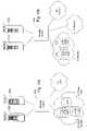
- system 200that includes a storage switch in accordance with the invention is illustrated in FIG. 2 .
- system 200includes a plurality of servers 202 .
- servers 202For purposes of illustration only, three servers 202 are shown, although more or fewer servers could be used in other embodiments. Although not shown, the servers could also be coupled to a LAN.
- each server 202is connected to a storage switch 204 . In other embodiments, however, each server 202 may be connected to fewer than all of the storage switches 204 present.
- the connections formed between the servers and switchescan utilize any protocol, although in one embodiment the connections are either Fibre Channel or Gigabit Ethernet (carrying packets in accordance with the iSCSI protocol). Other embodiments may use the Infiniband protocol, defined by Intel Inc., or other protocols or connections.
- each switch 204is in turn connected to each of a plurality of storage devices or subsystems 206 . Nonetheless, in other embodiments, each switch 204 may be connected to fewer than all of the storage devices or subsystems 206 .
- the connections formed between the storage switches 204 and storage devices 206can utilize any protocol, although in one embodiment the connections are either Fibre Channel or Gigabit Ethernet.
- one or more switches 204are each coupled to a Metropolitan Area Network (MAN) or Wide Area Network (WAN) 208 , such as the Internet.
- MANMetropolitan Area Network
- WANWide Area Network
- IPInternet Protocol
- management stations 210are connected to each storage switch 204 , to each server 202 , and to each storage device 206 .
- management stationsare illustrated as distinct computers, it is to be understood that the software to manage each type of device could collectively be on a single computer.
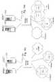
- FIG. 3shows an alternative embodiment of a system in accordance with the invention.
- two SANs 302 , 304are formed, each using one or more storage switches 204 in accordance with an embodiment of the invention.
- the SANs 302 and 304are coupled through a WAN 208 , such as the Internet, by way of switches 204 .
- Connections 208can be any standard or protocol, but in one embodiment will be Packet over SONET (PoS) or 10 Gigabit Ethernet.
- PoSPacket over SONET
- 10 Gigabit Ethernet10 Gigabit Ethernet
- FIG. 4shows still another embodiment of a system in accordance with the invention wherein switches 204 are coupled directly to one another. In any of the embodiments shown in FIG. 2 or 3 , if more than one switch is used, those switches could be coupled as illustrated in FIG. 4 .
- a storage switch in accordance with the inventionenables a centralized management of globally distributed storage devices, which can be used as shared storage pools, instead of having a huge number of management stations distributed globally and an army of skilled management personnel.
- Such a storage switchis an “intelligent” switch, and, as can be seen by comparing FIG. 2 to FIG. 1 , the functions of switch, appliance, and gateway have effectively been united in a storage switch 204 in accordance with an embodiment of the invention.
- Such a storage switch 204in addition to its switching function, provides the virtualization and storage services (e.g., mirroring) that would typically be provided by appliances in conventional architectures, and it also provides protocol translation.
- a storage switch in accordance with some embodiments of the inventionalso performs additional functions (for instance, data security through a Virtual Private Network).
- additional functionsinclude functions that are performed by other devices in conventional systems, such as load balancing, which is traditionally performed by the servers, as well as other functions not previously available in conventional systems, such as Quality of Service for storage access.
- the Quality of Service for storage access functionis “application aware”—that is, the Quality of Service provided is specified by the nature of the application initiating a connection to a storage target.
- the intelligence of a storage switch in accordance with an embodiment of the inventionis distributed to every switch port. This distributed intelligence allows for system scalability and availability.
- the distributed intelligenceallows a switch in accordance with an embodiment of the invention to process data at “wire speed,” meaning that a storage switch 204 introduces no more latency to a data packet than would be introduced by a typical network switch (such as switch 112 in FIG. 1 ).
- “wire speed” for the switchis measured by the connection to the particular port.
- the storage switchcan keep up with an OC-48 speed (2.5 bits per ns).
- a two Kilobyte packet (with 10 bits per byte) moving at OC-48 speedtakes as little as eight microseconds coming into the switch.
- a one Kilobyte packettakes as little as four microseconds.
- wire-speed processingwhen the term “wire-speed” processing is used herein, it does not mean that such processing needs as few as 400 ns to process a 100-byte packet. However, it does mean that the storage switch can handle the maximum Ethernet packet of 1500 bytes (with ten-bit encoding, so that a byte is ten bits) at OC-48 speed, i.e., in about 6 ⁇ s (4 ⁇ s per Kilobyte or 2.5 bits per ns), in one embodiment. In embodiments with a 1 Gb Ethernet port, where processing is generally defined as one bit per nanosecond, “wire-speed” data for that port will be 10 ⁇ s per Kilobyte, indicating that the switch has up to 10 ⁇ s to process a Kilobyte. In embodiments with a 2 Gb Fibre Channel port, “wire speed” will be 5 ⁇ s per Kilobyte. Still other embodiments may process data at ten Gigabit Ethernet or OC-192 speeds or faster.
- virtualizationessentially means the mapping of a virtual target space subscribed to by a user to a space on one or more physical storage target devices.
- the terms “virtual” and “virtual target”come from the fact that storage space allocated per subscription can be anywhere on one or more physical storage target devices connecting to a storage switch 204 .
- the physical spacecan be provisioned as a “virtual target” which may include one or more “logical units” (LUs).
- LUslogical units
- Each virtual targetconsists of one or more LUs identified with one or more LU numbers (LUNs), which are frequently used in the iSCSI and FC protocols.
- Each logical unitis generally comprised of one or more extents—a contiguous slice of storage space on a physical device.
- a virtual targetmay occupy a whole storage device (one extent), a part of a single storage device (one or more extents), or parts of multiple storage devices (multiple extents).
- the physical devices, the LUs, the number of extents, and their exact locationsare immaterial and invisible to a subscriber user.
- each virtual targetbelongs to one or more “pools,” sometimes referred to herein as “domains.” Only users of the same domain are allowed to share the virtual targets in their domain. Domain-sets can also be formed that include several domains as members. Use of domain-sets can ease the management of users of multiple domains, e.g., if one company has five domains but elects to discontinue service, only one action need be taken to disable the domain-set as a whole. The members of a domain-set can be members of other domains as well.
- FIG. 5illustrates a function block diagram of a storage switch 204 in accordance with an embodiment of the invention.
- the storage switch 204includes a plurality of linecards 502 , 504 , and 506 , a plurality of fabric cards 508 , and two system control cards 510 , each of which will be described in further detail below.
- Each of the two System Control Cards (SCCs) 510connects to every line card 502 , 504 , 506 .
- such connectionsare formed by I 2 C signals, which are well known in the art, and through an Ethernet connection with the SCC.
- the SCCcontrols power up and monitors individual linecards, as well as the fabric cards, with the I 2 C connections.
- the SCCuses inter-card communication over the ethernet connections, the SCC also initiates various storage services, e.g., snapshot and replicate, discussed in Provisional Application No. 60/325,704.
- the SCCmaintains a database 512 that tracks configuration information for the storage switch as well as all virtual targets and physical devices attached to the switch, e.g., servers and storage devices.
- the databasekeeps information regarding usage, error and access data, as well as information regarding different domains and domain sets of virtual targets and users.
- the records of the databaseare referred to herein as “objects.”
- Each initiator (e.g., a server) and target (e.g., a storage device)has a World Wide Unique Identifier (WWUI), which are known in the art.
- WWUIWorld Wide Unique Identifier
- the databaseis maintained in a memory device within the SCC, which in one embodiment is formed from flash memory, although other memory devices will also be satisfactory.
- the storage switch 204can be reached by a management station 210 through the SCC 510 using an ethernet connection. Accordingly, the SCC also includes an additional Ethernet port for connection to a management station. An administrator at the management station can discover the addition or removal of storage devices or virtual targets, as well as query and update virtually any object stored in the SCC database 512 .
- the SCCsoperate in a high availability mode wherein if one SCC fails, the other becomes the primary controller.
- Fabric CardsIn one embodiment of switch 204 , there are three fabric cards 508 , although other embodiments could have more or fewer fabric cards. Each fabric card 508 is coupled to each of the linecards 502 , 504 , 506 in one embodiment and serves to connect all of the linecards together. In one embodiment, the fabric cards 508 can each handle maximum traffic when all linecards are populated. Such traffic loads handled by each linecard are up to 160 Gbps in one embodiment although other embodiments could handle higher or lower maximum traffic volumes. If one fabric card 508 fails, the two surviving cards still have enough bandwidth for the maximum possible switch traffic: in one embodiment, each linecard generates 20 Gbps of traffic, 10 Gbps ingress and 10 Gbps egress. However, under normal circumstances, all three fabric cards are active at the same time. From each linecard, the data traffic is sent to any one of the three fabric cards that can accommodate the data.
- Linecardsform connections to servers and to storage devices.
- storage switch 204supports up to sixteen linecards although other embodiments could support a different number.
- three different types of linecardsare utilized: Gigabit Ethernet (GigE) cards 502 , Fibre Channel (FC) cards 504 , and WAN cards 506 .
- Gigabit Ethernet (GigE) cards 502are for Ethernet connections, connecting in one embodiment to either iSCSI servers or iSCSI storage devices (or other Ethernet based devices).
- the FC cards 504are for Fibre Channel connections, connecting to either Fibre Channel Protocol (FCP) servers or FCP storage devices.
- the WAN cards 506are for connecting to a MAN or WAN.
- FIG. 6illustrates a functional block diagram of a generic line card 600 used in one embodiment of a storage switch 204 in accordance with the invention.
- the illustrationshows those components that are common among all types of linecards, e.g., GigE 502 , FC 504 , or WAN 506 .
- other types of linecardscan be utilized to connect to devices using other protocols, such as Infiniband. The differences in the linecards are discussed subsequently.
- Each line card 600includes a plurality of ports 602 .
- the portsform the linecard's connections to either servers or storage devices. Eight ports are shown in the embodiment illustrated, but more or fewer could be used in other embodiments.
- each GigE cardcan support up to eight 1 Gb Ethernet ports
- each FC cardcan support up to either eight 1 Gb FC ports or four 2 Gb FC ports
- each WAN cardcan support up to four OC-48 ports or two OC-192 ports.
- the maximum possible connectionsare 128 ports per switch 204 .
- the ports of each linecardare full duplex and connect to either a server or other client, or to a storage device or subsystem.
- each port 602has an associated memory 603 .
- each portmay have its own memory device or the ports may all be coupled to a single memory device. Only one memory device is shown here coupled to one port for clarity of illustration.
- each portis associated with a Storage Processor Unit (SPU) 601 .
- the SPUrapidly processes the data traffic allowing for wire-speed operations.
- the SPUincludes several elements: a Packet Aggregation and Classification Engine (PACE) 604 , a Packet Processing Unit (PPU) 606 , an SRAM 605 , and a CAM 607 .
- PACEPacket Aggregation and Classification Engine
- PPUPacket Processing Unit
- SRAM 605SRAM
- CAM 607CAM
- Still other embodimentsmay use more or fewer elements or could combine elements to obtain the same functionality.
- some embodimentsmay include a PACE and a PPU in the SPU, but the SPU may share memory elements with other SPUs.
- Each portis coupled to a Packet Aggregation and Classification Engine (PACE) 604 .
- PACEPacket Aggregation and Classification Engine
- the PACE 604aggregates two ports into a single data channel having twice the bandwidth. For instance, the PACE 604 aggregates two 1 Gb ports into a single 2 Gb data channel.
- the PACEclassifies each received packet into a control packet or a data packet, as described in Provisional Application No. 60/325,704. Control packets are sent to the CPU 614 for processing, via bridge 616 .
- Data packetsare sent to a Packet Processing Unit (PPU) 606 , discussed below, with a local header added.
- PPUPacket Processing Unit
- the local headeris sixteen bytes resulting in a data “cell” of 64 bytes (16 bytes of header and 48 bytes of payload).
- the local headeris used to carry information and used internally by switch 204 .
- the local headeris removed before the packet leaves the switch.
- a “cell”is a transport unit that is used locally in the switch that includes a local header and the original packet (in some embodiments, the original TCP/IP headers are also stripped from the original packet). Nonetheless, not all embodiments of the invention will create a local header or have “internal packets” (cells) that differ from external packets. Accordingly, the term “packet” as used herein can refer to either “internal” or “external” packets.
- the classification functionhelps to enable a switch to perform storage virtualization and protocol translation functions at wire speed without using a store-and-forward model of conventional systems.
- Each PACEhas a dedicated path to a PPU 606 while all four PACEs in the illustrated embodiment share a path to the CPU 614 , which in one embodiment is a 104 MHz/32 (3.2 Gbps) bit data path.
- the PPU 606performs virtualization and protocol translation on-the-fly, meaning, the cells are not buffered for such processing, as described in Provisional Application No. 60,325,704. It also implements other switch-based storage service functions, described later.
- the PPUis capable, in one embodiment, of moving cells at OC-48 speed or 2.5 Gbps for both the ingress and egress directions, while in other embodiments it can move cells at OC-192 speeds or 10 Gbps.
- the PPUin one embodiment includes an ingress PPU 606 1 and an egress PPU 606 2 , which both run concurrently.
- the ingress PPU 606 1receives incoming data from PACE 604 and sends data to the Traffic Manager 608 i while the egress PPU 606 2 receives data from Traffic Manager 608 e and sends data to a PACE 604 .
- the egress PPU 606 2receives data from Traffic Manager 608 e and sends data to a PACE 604 .
- all PPUs 606will include both an ingress and an egress PPU and that only one PPU is shown in FIG. 6 with both ingress and egress PPUs for clarity of illustration.
- VTDVirtual Target Descriptor
- the VTDis derived from an object in the SCC database and usually contains a subset of information that is stored in the associated object in the SCC database.
- An example of the fields in a VTD in one embodiment of the inventionare shown in FIG. 7 a . Nonetheless, other embodiments of the invention may have a VTD with more, fewer, or different fields.
- PTDsPhysical Target Descriptors
- VTDsPhysical Target Descriptors
- the PTDdescribes the actual physical devices, their individual LUs, or their individual extents (a contiguous part of or whole LU) and will include information similar to that for the VTD.
- the PTDis derived from an object in the SCC database.
- An example of the fields in a PTD in one embodiment of the inventionare shown in FIG. 7 b . Nonetheless, other embodiments of the invention may have a PTD with more, fewer, or different fields.
- the PPUs 606are connected to an SRAM 605 and CAM 607 .
- SRAM 605stores a VTD and PTD database.
- a listing of VTD Identifiers (VTD IDs), or addresses, as well as PTD Identifiers (PTD IDs),is also maintained in the PPU CAM 607 for quick accessing of the VTDs.
- VTD IDsare indexed (mapped) using a TCP Control Block Index and a LUN.
- the PTD IDsare indexed using a VTD ID.
- the CAM 607contains a route table, which is updated by the CPU when routes are added or removed.
- each PPUwill be connected with its own CAM and SRAM device, or the PPUs will all be connected to a single CAM and/or SRAM.
- a task control blockis established in the PPU SRAM 607 to track the status of the request.
- ITCBsingress task control blocks
- ETCBsegress task control blocks
- Traffic ManagerThere are two traffic managers (TMs) 608 on each linecard 600 : one TM 608 i for ingress traffic and one TM 608 e for egress traffic.
- the ingress TMreceives cells from all four SPUs, in the form of 64-byte data cells, in one embodiment. In such an embodiment, each data cell has 16 bytes of local header and 48 bytes of payload.
- the headercontains a FlowID that tells the TM the destination port of the cell.
- the SPUmay also attach a TM header to the cell prior to forwarding the cell to the TM. Either the TM or the SPU can also subdivide the cell into smaller cells for transmission through the fabric cards in some embodiments.
- the ingress TMsends data cells to the fabric cards via a 128-bit 104 Mhz interface 610 in one embodiment. Other embodiments may operate at 125 Mhz or other speeds.
- the egress TMreceives the data cells from the fabric cards and delivers them to the four SPUs.
- Both ingress and egress TMshave a large buffer 612 to queue cells for delivery.
- Both buffers 612 for the ingress and egress TMsare 64 MB, which can queue a large number of packets.
- the SPUscan normally send cells to the ingress TM quickly as the outgoing flow of the fabric cards is as fast as the incoming flow. Hence, the cells are moving to the egress TM quickly.
- an egress TMmay be backed up because the outgoing port is jammed or being fed by multiple ingress linecards. In such a case, a flag is set in the header of the outgoing cells to inform the egress SPU to take actions quickly.
- the egress TMalso sends a request to the ingress SPU to activate a flow control function, discussed further below, used in providing Quality of Service for Storage access. It is worth noting that, unlike communications traffic over the Internet, for storage traffic dropping a packet or cell is unacceptable. Therefore, as soon as the amount of cells in the buffer exceeds a specified threshold, the SPU must activate its flow control function to slow down the incoming traffic to avoid buffer overflow.
- the fabric connection 610converts the 256-bit parallel signals of the TM (128 bits ingress and 128 bits egress, respectively), into a 16-bit serial interface (8-bit ingress and 8-bit egress) to the backplane at 160 Gbps.
- the backplaneis running at one sixteenth of the pins but sixteen times faster in speed. This conversion enables the construction of a high availability backplane at a reasonable cost without thousands of connecting pins and wires.
- there are three fabric cards in one embodimentthere are three high-speed connectors on each linecard in one embodiment, wherein the connectors each respectively connect the 8-bit signals to a respective one of the three fabric cards. Of course, other embodiments may not require three fabric connections 610 .
- CPU 614On every linecard there is a processor (CPU) 614 , which in one embodiment is a PowerPC 750 Cxe.
- CPU 614connects to each PACE with a 3.2 Gb bus, via a bus controller 615 and a bridge 616 .
- CPU 614also connects to each PPU, CAM and TM, however, in some embodiments this connection is slower at 40 Mbps. Both the 3.2 Gb and 40 Mb paths allow the CPU to communicate with most devices in the linecard as well as to read and write the internal registers of every device on the linecard, download microcode, and send and receive control packets.
- the CPU on each linecardis responsible to initialize every chip at power up and to download microcode to the SPUs and each port wherever the microcode is needed. Once the linecard is in running state, the CPU processes the control traffic. For information needed to establish a virtual target connection, the CPU requests the information from the SCC, which in turn gets the information from an appropriate object in the SCC database.
- each type of linecarde.g., GigE, FC, or WAN are distinct as each linecard only supports one type of port in one embodiment.
- Each type of port for one embodimentis described below.
- other linecard portscould be designed to support other protocols, such as Infiniband in other embodiments.
- a gigabit Ethernet portconnects to iSCSI servers and storage devices. While the GigE port carries all kinds of Ethernet traffic, the only network traffic generally to be processed by a storage switch 204 at wire speed in accordance with one embodiment of the invention is an iSCSI Packet Data Unit (PDU) inside a TCP/IP packet. Nonetheless, in other embodiments packets in accordance with other protocols (like Network File System (NFS)) carried over Ethernet connections may be received at the GigE Port and processed by the SPU and/or CPU.
- PDUiSCSI Packet Data Unit
- NFSNetwork File System
- the GigE portreceives and transmits TCP/IP segments for virtual targets or iSCSI devices.
- TCP connectionFor a virtual target, both the linecard CPU 614 and the SCC 510 are involved.
- a TCP control blockis created and stored in the GigE port memory 603 .
- a VTDmust also be retrieved from an object of the SCC database and stored in the CPU SDRAM 605 for the purpose of authenticating the connection and understanding the configuration of the virtual target.
- the TCP Control Blockidentifies a particular TCP session or iSCSI connection to which the packet belongs, and contains in one embodiment, TCP segment numbers, states, window size, and potentially other information about the connection.
- the TCP Control Blockis identified by an index, referred to herein as the “TCP Control Block Index.”
- a VTD for the connectionmust be created and stored in the SPU SRAM 605 .
- the CPUcreates the VTD by retrieving the VTD information stored in its SDRAM and originally obtained from the SCC database.
- a VTD IDis established in a list of VTD IDs in the SPU CAM 607 for quick reference to the VTD.
- the VTD IDis affiliated with and indexed by the TCP Control Block Index.
- the portWhen the port receives iSCSI PDUs, it serves essentially as a termination point for the connection, but then the switch initiates a new connection with the target. After receiving a packet on the ingress side, the port delivers the iSCSI PDU to the PACE with a TCP Control Block Index, identifying a specific TCP connection. For a non-TCP packet or a TCP packet not containing an iSCSI PDU, the port receives and transmits the packet without acting as a termination point for the connection. Typically, the port 602 communicates with the PACE 604 that an iSCSI packet is received or sent by using a TCP Control Block Index. When the TCP Control Block Index of a packet is ⁇ 1, it identifies a non-iSCSI packet.
- FC PortAn FC port connects to servers and FC storage devices.
- the FC portappears as a fibre channel storage subsystem (i.e., a target) to the connecting servers, meaning, it presents a large pool of virtual target devices that allow the initiators (e.g., servers) to perform a Process Login (PLOGI or PRLI), as are understood in the art, to establish a connection.
- the FC portaccepts the GID extended link services (ELSs) and returns a list of target devices available for access by that initiator (e.g., server).
- GID extended link servicesELSs
- the portWhen connecting to fibre channel storage devices, the port appears as a fibre channel F-port, meaning, it accepts a Fabric Login, as is known in the art, from the storage devices and provides name service functions by accepting and processing the GID requests—in other words, the port will appear as an initiator to storage devices.
- an FC portcan connect to another existing SAN network, appearing in such instances as target with many LUs to the other network.
- the linecard CPUmust go through both sending Fabric Logins, Process Logins, and GIDs as well as receive the same.
- the SCCsupports an application to convert FC ELS's to iSNS requests and responses.
- the same database in the SCCkeeps track both the FC initiators (e.g., servers) and targets (e.g., storage devices) as if they were iSCSI initiators and targets.
- an FC portWhen establishing an FC connection, unlike for a GigE port, an FC port does not need to create TCP control blocks or their equivalent; all the necessary information is available from the FC header. But, a VTD (indexed by a D_ID) will still need to be established in a manner similar to that described for the GigE port.
- An FC portcan be configured for 1 Gb or 2 Gb.
- a 1 Gb porttwo ports are connected to a single PACE as illustrated in FIG. 6 ; but in an embodiment where it is configured as a 2 Gb port, port traffic and traffic that can be accommodated by the SPU should match to avoid congestion at the SPU.
- the portconnects to the PACE with a POS/PHY interface in one embodiment.
- Each portcan be configured separately, i.e. one PACE may have two 1 Gb ports and another PACE has a single 2 Gb port.
- WAN PortsIn embodiments that include a WAN linecard, the WAN linecard supports OC-48 and OC-192 connections in one embodiment. Accordingly, there are two types of WAN ports: OC-48 and OC-192. For OC-48, there is one port for each SPU. There is no aggregation function in the PACE, although there still is the classification function.
- a WAN portconnects to SONET and works like a GigE port as it transmits and receives network packets such as ICMP, RIP, BPG, IP and TCP. Unlike the GigE port, a WAN port in one embodiment supports network security with VPN and IPSec that requires additional hardware components.
- a storage switch in accordance with an embodiment of the inventionperforms various switch-based storage operations, including pooling and provisioning, Quality of Service for storage access, and load balancing, each of which will be discussed below.
- a system in accordance with an embodiment of the inventionincludes a switch 204 coupled to one or more servers 202 and to one or more physical devices 206 , i.e., storage devices or subsystems.
- Each physical targetis comprised of one or more logical units (LUs) 207 . It is from these LUs that virtual targets will ultimately be formed.
- LUslogical units
- the switchneeds to be “aware” of the physical storage devices attached and/or available for access by it as well as the characteristics of those physical storage devices. Accordingly, in one embodiment of the invention, when a storage device or an initiator device is connected to or registered with the switch, the switch must learn about the performance characteristics of the new device.
- the switchincludes a utility program, which can measure storage access time, data transfer rate, cache support, number of alternate paths to the device, RAID support, and allowable maximum commands for the LUs of the physical device. In some embodiments, once a device is connected to the switch, the utility program will automatically discover the device and automatically gather the required information without any user or other intervention.
- the switchwill “discover” the addition/removal of a device when there is a disturbance or reset on the signal lines to the port. Once the device is “discovered,” various inquiries are sent to the device to gather information regarding performance characteristics. For instance, read/write commands can be sent to measure transfer rate or to check access time. Alternatively, in some embodiments, the obtaining of performance characteristics can be done by having an administrator enter the performance characteristics at a management station 210 , wherein the characteristics can then be provided to a switch 204 .
- the switchclassifies the device based on a policy. For example, devices with the best characteristics may be classified as Platinum devices. Those with intermediate performance characteristics as Gold or Silver devices. Those with the worst performance characteristics as Bronze devices.
- policiesthat are defined are infinite and will vary amongst embodiments of the invention.
- an administratorcould further subdivide the policies, e.g., Platinum Building 1 , Platinum Building 2 , and assign resources to such subdivided policies. Nonetheless, an example of policies used in one embodiment of the invention are shown in Table 1 below:
- each storage deviceis comprised of one or more LUs, all the LUs of a particular storage device are assigned to the same pool. However, in one embodiment, each LU is considered by the switch as a separate storage node and each LU is described by an LU object in the SCC database 512 . Thus, each pool has as members the LUs. In one embodiment, assignment to a pool is done independent of the protocol under which the physical storage device operates, e.g., iSCSI or Fiber Channel.
- each poolis defined in a switch by a listing for the pool of the LUs assigned to it, which listing is stored in the SCC database 512 in one embodiment.
- Such a listingmay be comprised of pointers to the LU objects.
- each poolwill be accessible only to users with particular characteristics. For example, a storage pool may be established for those users located in a Building 1 , where the pool is entitled “Building 1 Shared Gold Storage Pool.” Another exemplary pool may be entitled “Engineering Exclusive Silver Storage Pool” and may be exclusively accessible by the engineering team at a particular company. Of course an infinite variation of pools could be established and those described and illustrated are exemplary only.
- a Default Poolallows access to anyone with access to the storage network.
- a “No Pool,” in contrast,is not generally accessible to users and is only accessible to the switch itself or to the system administrator.
- the LUscan be reassigned to different pools by the switch itself or by a system administrator. For instance, an LU may initially be placed in the No Pool, tested, and then later moved to the default pool or other pool.
- Service Level Agreementsare sometimes used in network communications, but have not generally been used in the context of a storage network and have not been used in storage networks with Quality of Service (QoS) policies.
- QoSQuality of Service
- a usercan select the conditions of storing and retrieving data.
- a QoS policyis defined by three elements: provisioning a virtual target, provisioning an initiator connection, and defining a user domain. Each is discussed below. Nonetheless, some embodiments may not require all three elements to define a QoS policy. For instance, some embodiments may only require provisioning a virtual target and provisioning an initiator connection, but not the user domain. Other embodiments may use different elements altogether to define a QoS policy.
- a virtual targetcan be created from those LUs.
- the serversand their respective users will “see” one or more virtual targets 902 , each comprised of one or more extents 907 , but they will not necessarily “see” the physical devices 206 .
- An extentis a contiguous part of or a whole LU from a physical device.
- each extent in the example virtual target 902is formed from entire LUs from several physical devices.
- each virtual targetmay still be referenced by an LUN from an initiator, such as a server, which doesn't realize a target is “virtual.”
- the composition of the virtual targets, including protocols used by the LUis irrelevant to the server.
- each virtual targetis comprised of extents that map to the LUs of physical devices 206 .
- a userwill select several characteristics for the virtual target in one embodiment of the invention including:
- the switchanalyzes the available resources from the selected pool to determine if the virtual target can be formed, and in particular the switch determines if a number of LUs (or parts of LUs) to meet the size requirement for the virtual target are available. If so, the virtual target is created with one or more extents and a virtual target object is formed in the SCC database identifying the virtual target, its extents, and its characteristics. Examples of user-selected characteristics for four virtual targets are shown in Table 2 below:
- a switch in accordance with an embodiment of the inventioncan also modify existing virtual targets with new or different information or delete virtual targets when they are no longer needed.
- the initiatorWhen a server or other initiator is connected to a switch and the initiator supports iSNS or SLP, in one embodiment the initiator will register itself with the switch, resulting in an initiator object stored in the SCC database. In other embodiments, however, the switch will include an access provisioning function which creates, updates, or deletes an initiator connection.
- the connection between the switch and an initiator(such as a server)—a user will specify various parameters shown for one embodiment in Table 3:
- the server WWUI connection detailsuch as protocol (e.g., GigE or Fiber Channel) exclusive or shared source and destination IP addresses minimum and maximum percentage of bandwidth # of connections required by the server access security read only or read/write VPN enabled
- Some or all of the above informationis saved in an initiator object stored in the SCC database. When the connection is removed, the initiator object will be deleted.
- the switch, the management station, or other network managementthen creates a storage pool for the particular connection, specifying the LUs available to the initiator to form virtual targets.
- virtual targetscan be assigned to a pool accessible only to those with specified characteristics.
- virtual targetscan be assigned to a user-specific domain (sometimes referred to herein as the User's Domain), a default domain (accessible to anyone), or a No Domain.
- Each domainwill be identified, in one embodiment, by an object in the SCC database that includes a listing of all the virtual targets assigned to the domain.
- the No Domainmay include spare virtual targets, members of mirrored virtual targets, or remote virtual targets from another switch.
- the virtual target No Domainis a parking place for certain types of virtual targets.
- poolswill be referred to herein as “domains,” but when referencing physical devices, pools will continue to be referred to as “pools.” It is to be understood, however, that conceptually “pools” and “domains” are essentially the same thing.
- a virtual targetis provisioned that meets the initiator's requirements and placed into an accessible pool for the initiator or a previously provisioned virtual target is made accessible to the initiator, e.g., by moving the virtual target to the initiator's user domain from another domain such as the No Domain or Default Domain. (Note that either the virtual target or the initiator connection can be provisioned first—there is no requirement that they be provisioned in a particular order).
- both the virtual target object and initiator objectare read from the SCC database and information regarding the initiator connection and virtual target is passed to the relevant linecard(s) for use in processing the requests.
- FIGS. 10 a - dExamples of provisioning virtual targets are given with reference to FIGS. 10 a - d .
- FIG. 10 aassume there are physical devices having a total of 6 LUs—LU 1 , LU 2 , LU 3 , LU 4 , LU 5 , LU 6 —coupled to a switch and all are placed in a pool accessible to two initiators X and Y the “X-Y User Pool.” If initiator X requires two virtual targets, then in one situation the LUs are provisioned to form virtual targets VT 1 and VT 2 , where VT 1 includes as extents LUs 1 - 3 and VT 2 includes as extents LUs 4 - 6 , where both VT 1 and VT 2 are placed in the server X user domain, thus allowing server X to access both virtual targets as shown in FIG.
- Server Ywill not have access to either VT 1 or VT 2 since no virtual targets have been placed in the Y user domain.
- VT 1 and VT 2may be provisioned as before, but VT 1 is placed in server X's user domain while VT 2 is placed in server Y's user domain.
- VT 1 and VT 2will be created as members of the virtual target M.
- VT 1 and VT 2will be placed in the switch's No Domain while M is made accessible to Y, as shown in FIG. 10 d .
- members of MVT 1 and VT 2 are not independently accessible.
- server Xis coupled to switch A and server Y is coupled to switch B.
- VT 1is provisioned as part of server X's domain in switch A while VT 2 is provisioned as part of server Y's domain in switch B.
- switch Bis provisioned as an initiator to switch A, and switch A is provisioned as an initiator to switch B. In this manner, switch A can access VT 2 via switch B, and switch B can access VT 1 via switch A.
- VT 1referred to here as VT 1 ′ since access is via switch B
- VT 2referred to here as VT 2 ′
- server Xcan be included in server X's domain
- switch Bsees switch A as an initiator
- switch Asees switch B as an initiator
- an administratorwill make selected resources of switch B available to other switches, e.g., switch A, and vice versa.
- certain domainsmay be defined to allow access to their resources by multiple switches.
- access to a virtual target by an initiatorwill be provided in accordance with an SLA selected by a user of which the QoS policy is only a part.
- SLAselected by a user of which the QoS policy is only a part.
- ID of initiatoridentifies initiator object
- ID of virtual targetidentifies virtual target object
- ID of User Domain ID of extent getting provisionedAutomatically increase size of virtual target-on or off Automatically increase size at what threshold Automatically increase what percentage of size
- Numbers of local mirrorsmay be restricted to possible range-see Table 2)
- Local domain ID for each local mirrored membermay be restricted it to possible range-see Table 2)
- Numbers of remote mirrorsmay be restricted to possible range-see Table 2)
- Remote domain IDidentified locally) for each remote mirrored member (may be restricted to Possible range-see Table 2)
- Error Threshold in event auto migrationis On (see Table 2) Backup Enable (Disabled by default) Backup Schedule Pool ID for Backup LU
- the userWhen a user agrees to an SLA, the user also selects a quality of service (QoS) policy.
- QoSquality of service
- the QoS policyis generally defined by virtual target (as provisioned), the initiator connection (as provisioned), and the User Domain. Accordingly, referring again to Table 4, above, the first three entries in the table—“ID of Initiator,” “ID of Virtual Target” and “ID of User Domain”—will inherently describe the QoS policy since the attributes of the initiator connection and virtual target were defined when these items were provisioned. For example, the minimum and maximum bandwidth for the initiator connection has already been identified (see Tables 2 and 3).
- the User Domainassists in defining the policy by determining, for example, if the initiator connection or virtual target connection is slower and forcing the QoS to the slower of the two.
- the User Domainmay not be necessary in all embodiments.
- other embodimentsmay define an SLA using more, fewer, or different parameters than those shown in Table 4 above.
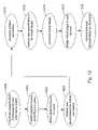
- FIG. 12summarizes the steps to provision the virtual targets and connections in order to be able to provide QoS in one embodiment.
- a switchin accordance with an embodiment of the invention discovers and determines the characteristics of physical devices in communication with the switch, step 1202 .
- the switchthen classifies those devices, step 1204 , and associates those devices with a particular storage pool, step 1204 .
- the switchwill receive information for an initiator connection, step 1208 , and will then provision the connection, step 1210 , creating an object in the SCC database.
- the switchwill also receive parameters for a virtual target, step 1212 , and will provision the virtual target in accordance with those parameters, step 1214 , if the resources are available, creating an object in the SCC database.
- steps 1208 - 1214can be performed in any order, the order shown in FIG. 12 being exemplary only.
- a user domainis created and the virtual target placed in the user domain or the virtual target is placed in a pre-existing user domain, step 1216 .
- a usercould also attempt to access a previously provisioned virtual target (hence, step 1214 may not be necessary for every connection).
- a switchin accordance with an embodiment of the invention receives SLA/QoS parameters, step 1218 .
- each virtual target, each initiator connection, and each physical deviceis identified in the SCC database with information included in an object for the respective entity.
- Each virtual target object and physical target objectwill include a listing of extents or LUs that comprise it.
- An example of a Virtual Target objectin one embodiment of the invention, includes the following information:
- entity typewill identify whether the entity is a virtual target or physical target.
- Entity identifieris, in one embodiment, a WWUI, which may be created by the user in some embodiments.
- the “managing IP address”indicates the address of the device through which the entity is configured, e.g., a management station. For instance, a virtual target is configured through a management station, which is accessed through the SCC in one embodiment of the invention.
- Time stamp and flagsare used to track events such as when the virtual target or other entity was created or changed. Flags may be used to indicate various services or events in progress, such as copying of the data in a virtual target.
- Portsinclude a list of the ports through which the LU can be accessed and include information regarding the port names and linecard number, TCP/IP address or Fiber Channel 24-bit address, and whether the port is a primary or secondary port for the entity.
- Domain informationincludes the storage domain or pool to which the virtual target or entity belongs.
- SCN bit mapindicates system change notification for the virtual target.
- Capacity and inquiry informationindicates how big the virtual or physical target is as well as the inquiry information usually provided by a device vendor. For instance, inquiry information for a physical device will often identify its manufacturer whereas inquiry information for a virtual target will often identify the switch that created the virtual target.
- Each LU of a physical deviceis comprised of one or more contiguous pieces of storage space called an extent, which are used to form the virtual targets. Accordingly, “number of extents” identifies how many extents form the virtual target. “List of extents” identifies each of the extents, in one embodiment, by an offset and a size. For example, a 10 GB virtual target comprised of three extents may identify the extents in the “list of extents” as shown in Table 5:
- Extent locatoridentifies exactly where the extents are located, i.e., on which physical devices.
- the above 10 GB, 3-extent virtual targetmay have the following extent locator:
- the first extent of the virtual targetis mapped to physical storage device 2 (Table 6) starting at an offset of 5 GB (Table 5) and extending for 2 GB (Table 5).
- the second extent (Table 5)is mapped to physical storage device 1 (Table 6) starting at an offset 3 GB (Table 6) and extending for 5 GB (Table 5).
- the third extentis mapped to physical storage device 3 (Table 5) starting at an offset 15 GB (Table 6) and extending for 3 GB (Table 5).
- every member of the mirrored virtual targetwill have an identical extent list, although the extent locators will be different.
- “Virtual mode pages”identify the mode pages frequently found in SCSI commands as will be understood in the art. This information includes the block transfer size, immediate data support, or any unique information that application software with SCSI-mode-page commands can set and retrieve.
- Quality of service policydetermines the service attributes for the virtual target and is selected at the time of provisioning of the virtual target. In one embodiment, Quality of Service policy will be defined using the identifiers found in the first three entries of Table 4.
- “Statistics”are collected at run time of the virtual target by the switch in one embodiment of the invention. They may include usage, error, and performance data in one embodiment of the invention, and are further discussed below.
- the “SLA identifier”identifies an SLA object for information regarding the SLA.
- a switch in accordance with an embodiment of the inventionalso collects statistics.
- the following informationis collected by the SPU of the linecard connecting to the initiator:
- the CPU on each linecardperiodically requests the statistics from the SPU.
- the SPUresponds by returning the data.
- the SPUthen resets the data to zero and resumes collection.
- the CPUBased on the collected data, the CPU maintains the following statistics:
- the CPUforwards the statistics to the SCC and updates the relevant VTDs (stored in the SPUs).
- the SCCwill request the statistics from the CPU, and the CPU will provide them to the SCC.
- the SCCwill also reset its statistics periodically, e.g., weekly, to ensure that data is accurate and not over-accumulated.
- the minimum percentage of the initiator connection bandwidthis guaranteed by the QoS in one embodiment.
- the sum of all minimum bandwidths of all initiatorsmust be less than or equal to 100%.
- the maximum percentageprovides the allowable use of the connection when there are no other contending users on the same connection.
- the sum of maximum percentages of bandwidths of all initiatorscan exceed 100% of the bandwidth of the connection.
- QoSIn a conventional communications network (as opposed to a storage network), QoS is used to ensure that users get the percentage of data bandwidth of a connection that they paid for. It allows time-sensitive data such as audio and video to experience only acceptable interruptions by either negotiating a reserved data bandwidth before transmission or giving the time-sensitive transmission a higher priority in a congested situation.
- the QoSis enforced by prioritizing the switching traffic even at the expense of dropping packets.
- a requestincludes all packets sent back and forth from initiator to target until the request is complete, e.g., an iSCSI command PDU, an iSCSI R2T, an iSCSI write data PDU, and an iSCSI response PDU will form a single request.
- the data bandwidthin one embodiment, is calculated by the number of requests per second multiplying by the average transfer size of the request. For example, if the average transfer size is 8 KB, with 1000 requests per second, the bandwidth for the storage device will be 8 MB/sec (or 80 Mb/sec).
- a virtual targetsupports a maximum number of concurrent requests.
- An initiator accessing multiple virtual targetscan have a maximum number of requests sent that is equal to the sum of the maximum number of requests for all of the virtual targets it is accessing. But, when multiple initiators share one or more virtual targets, the maximum number of requests available are shared among the initiators, being prorated according to the respective QoS parameters of minimum percentage of bandwidth. For instance, if two initiators share access to a virtual target that can accommodate 100 concurrent requests, and initiator 1 gets a minimum of 70% of the bandwidth while initiator 2 gets a minimum of 30% of the bandwidth, then initially initiator 1 can send 70 requests and initiator 2 can send 30 requests. Nonetheless, because each initiator will have its own request size, a large request size may consume greater bandwidth and crowd out other initiators of smaller transfer sizes. Thus, adjustment of allowable requests by each initiator in order to guarantee a bandwidth range is performed in one embodiment as follows.
- the traffic managers (TMs) 608( FIG. 6 ) in both ingress and egress linecards monitor the transfer bandwidth of different connections.
- the TMalso schedules delivery based on QoS parameters.
- the TMguarantees that each shared connection gets its minimum bandwidth and is limited by its maximum bandwidth—in other words, the TM assures that each connection is within a specified range. To do so, in one embodiment, as packets accumulate inside the TM buffer 612 , such accumulation will indicate that an initiator has exceeded its limitations.
- the TMwill send a control message to the SPU indicating that the offending initiator should slow its connection.
- the SPUAfter receiving such a message, the SPU will reduce the number of allowable requests to the offending initiator while the number of allowable requests to the initiator that was receiving a smaller share would be increased.
- notification of the number of requests available to a servermay occur in the MaxCmdSN field of an iSCSI PDU
- an initiator A and an initiator Bboth have as their minimum bandwidth 50% of a shared initiator connection.
- initiator Asends 800 requests per second thus getting 80 MB per second of bandwidth on the connection.
- initiator Bsends 2000 requests per second, but gets only 8 MB per second of bandwidth.
- the switchmust reduce the number of requests from initiator A to reduce its requests to 700 per second to obtain 70 MB per second. Accordingly, the ingress traffic manager 608 1 will report to the ingress SPU that initiator A has exceeded its maximum and packets are accumulating in the buffer 612 i .
- the SPUin receiving the message, will reduce the number of allowable requests to A and increase those to B. Thus, initiator B will be able to send more requests on the connection. It should be noted that when the initiator is not maximizing the use of its allowable requests to even reach its minimum percentage bandwidth, no adjustment will be necessary. Further, because initiator B is not currently demanding 50% of the connection, initiator A is free to use up to (but not to exceed) its maximum allowed bandwidth.
- the prorated request numbers for each initiatorare adjusted when the TM 608 e on the egress linecard detects unfair bandwidth uses between the two initiators. It will detect such unfair bandwidth usage when the offending initiator has packets accumulated in the buffer 612 e .
- the egress TM 608 eWhen the connection is not shared and becomes congested due to the physical storage device itself being busy, the egress TM 608 e will inform the PPU because packets are accumulating in the buffer 612 e . Again, the SPU will then reduce the number of allowable requests to slow down the initiator(s).
- the switchwill also match the bandwidth between the initiator and the storage device. For example, to support an initiator having a minimum of 100% of a 1 Gb connection, no other virtual target can be allocated on the storage connection. But when an initiator only requires 50% bandwidth of the connection, the remaining 50% can be allocated to another virtual target.
- the priority of a connectiondetermines which command gets delivered first by the switch traffic manager of a linecard.
- initiator ingress target port egress port detection actions not not shared egress buffer thresholdreducing allowable shared requests shared not shared ingress buffer threshold reducing allowable requests from offending initiators not shared egress buffer threshold redistribute allowable shared (shared requests to different target) initiators not shared egress buffer threshold reducing allowable shared port requests to offending (different initiator targets) shared shared ingress and egress treat each virtual target buffer threshold separately as the above four cases
- the shared initiator ingress portis shared by initiators that are accessing different targets on different ports, so that the target egress port is not shared.
- Excessive bandwidth use by one of the initiatorsis detected in the ingress buffer by determining if a threshold has been exceeded, causing the buffer to back up beyond an acceptable point. Appropriate action is to reduce the allowable number of requests from the offending initiator.
- the initiator ingress portis not shared but the target egress port is shared, indicating that the same target is accessed by different initiators from different ports. Excessive bandwidth usage caused by an excessive number of requests by one of the initiators will be detected in the egress buffer. Appropriate action is to redistribute the number of allowable requests from the different initiators, e.g., decrease the number of requests allowed one initiator while increasing the number of requests to the other initiator.
- the initiator ingress portis not shared but the target egress port is shared, but in this instance different targets are accessed on the same egress port by different initiators.
- excessive bandwidthis detected in the egress buffer where each target is given a percentage of the connecting bandwidth. Appropriate action to take in such circumstances is to reduce the number of allowable requests to the offending initiator.
- the fifth situationindicates a shared initiator ingress port and a shared target egress port.
- Such decision makingtakes place in both ingress and egress buffers by looking to see if the buffer thresholds have been exceeded.
- Appropriate actionis to treat each virtual target separately as is done in the above four circumstances and to reduce the number of requests as required.
- Table 7is illustrative only. In other embodiments, other actions could occur to enforce QoS and other situations could occur that are not described above.
- Load balancingis utilized in one embodiment and occurs by selecting a path dynamically to reach a target device faster when more than one path is available to the target device. Load balancing is done dynamically (as opposed to statically, at fixed time intervals) on every port in the switch and for each request by utilizing the SPU processing power on each port.
- Failoveris a special case of load balancing and utilized in some embodiments of the invention. Failover will occur when one member of a mirrored target becomes unavailable or one path becomes unusable to a target that is accessible by multiple paths—in either case, the other member is accessed or the other path is utilized.
- the switchperforms two different types of actions related to load balancing:
- a switchwill also support a “pass-thru” configuration.
- the virtual targetis the physical target itself, and all commands “pass-thru” the switch without interpretation—e.g., without virtualization or translation.
- all load balance functionsare handled by the server itself.
- a switch in accordance with the inventiontracks the average response time of each target, including the response time of each of the members of a mirrored virtual target.
- the relevant statisticsare stored in each VTD, which is periodically updated by the CPU.
- the SPUreferring to the VTD
- the SPUselects the path with the shortest average response time and forwards the request on that path or it selects the mirrored member with the shortest average response time and forwards the request to that member. Note that with mirrored targets, a selection amongst mirrored members would not be performed for write operations since writes will be made to all members of a mirrored virtual target.
- the commandsare sent to the various paths/members alternately.
- multiple concurrent connectionswill only be used for iSCSI devices, as Fibre Channel does not currently support such multiple concurrent connections.
- Fibre Channeldoes not currently support such multiple concurrent connections.
- other embodiments using other protocolsmay also support multiple concurrent connections.
Landscapes
- Engineering & Computer Science (AREA)
- Computer Networks & Wireless Communication (AREA)
- Signal Processing (AREA)
- Computer Hardware Design (AREA)
- General Engineering & Computer Science (AREA)
- Data Exchanges In Wide-Area Networks (AREA)
Abstract
Description
- STORAGE SWITCH FOR STORAGE AREA NETWORK, Ser. No.: 10/051,321;
- PROTOCOL TRANSLATION IN A STORAGE SYSTEM, Ser. No.: 10/051,415;
- SERVERLESS STORAGE SERVICES, Ser. No.: 10/051,164;
- PACKET CLASSIFICATION IN A STORAGE SYSTEM, Ser. No.: 10/051,093;
- VIRTUALIZATION IN A STORAGE SYSTEM, Ser. No.: 10/051,396;
- POOLING AND PROVISIONING STORAGE RESOURCES IN A STORAGE NETWORK, Ser. No.: 10/050,974; and
- LOAD BALANCING IN A STORAGE NETWORK, Ser. No.: 10/051,053.
| TABLE 1 | |
| PERFORMANCE | Policy Name |
| PARAMETERS | Platinum | Gold | Silver | Bronze |
| Access time in milliseconds | >7 | >10 | >12 | >15 |
| Transfer rate in Megabytes/Sec | >30 | >20 | >15 | >10 |
| Max cache size in Megabytes | >32 | >16 | >8 | >1 |
| I/O per second rating | >3000 | >2000 | >1000 | >500 |
| Mbytes/second for backup | >8 | >5 | >3 | >1 |
| Mean Time Between Failure | >15 | >10 | >8 | >5 |
| (MTBF) in | ||||
| RAID Level | ||||
| 0, 1, 2, etc. 0 × | 1 | 5 | None | None |
| EE = none | ||||
| Maximum allowable commands | >100 | >50 | >25 | — |
- the size (e.g., in Gigabytes);
- a storage pool, although in one embodiment the user may select only from the storage pools which the user is permitted to access;
- desired availability, e.g., always available (data is critical and must not ever go down), usually available, etc.;
- the WWUI of the virtual target;
- a backup pool;
- user authentication data;
- number of mirrored members;
- locations of mirrored numbers (e.g., local or remote).
Still in other embodiments of the invention, different, additional, or fewer characteristics can also be selected.
| TABLE 2 |
| Virtual Target |
| Virtual Target | A | B | D | ||
| size | |||||
| 1 TB | 500 | 100 | 2 TB | ||
| storage pool | platinum | gold | bronze | bronze | |
| availability | always | always | high | high | |
| WWUI | drive A | drive B | drive C | drive D | |
| tape | 1 | tape 4 | |||
| authentication data | connection | connection | password | password | |
| ID and | ID and | ||||
| password | password | ||||
| # of mirrored | 3 | 2 | 2 | 1 | |
| locations of replicated | local | local | remote | none | |
| sites | |||||
| Switching priority (One | 1 | 2 | 3 | 4 | |
| of 4) (if all else is equal, | |||||
| which target has priority) | |||||
| Read Load Balance-on or | On | Off | Off | Off | |
| off-when mirroring | |||||
| chosen | |||||
| Type of Media for back- | Fastest | Fast | Medium | Slowest | |
| up (backup pool) | |||||
| Mirroring-on or off | On | On | Off | Off | |
| How many paths to stor- | 2 | 2 | 1 | 1 | |
| age from server (used | |||||
| for load balancing) | |||||
| Path to storage via how | 2 | 2 | 1 | 1 | |
| many switches | |||||
| Auto Migration to an- | Off | Off | On | Off | |
| other target on excessive | |||||
| errors-on or off | |||||
| Physical storage-exclu- | Exclusive | Exclusive | Exclusive | Shared | |
| sive or shared | |||||
| Virtual target-exclusive | Exclusive | Exclusive | Shared | Shared | |
| or shared | |||||
| VPN on WAN connec- | Yes | Yes | No | No | |
| tions | |||||
| IP Precedence (DiffServ, | Yes | Yes | No | No | |
| RFC 2474) | |||||
| MTBF | 15 yrs. | 10 yrs. | 5 yrs. | 5 yrs. | |
| TABLE 3 |
| Initiator Connection |
| the server WWUI | ||
| connection detail, such as protocol (e.g., GigE or Fiber Channel) | ||
| exclusive or shared | ||
| source and destination IP addresses | ||
| minimum and maximum percentage of bandwidth | ||
| # of connections required by the server | ||
| access security | ||
| read only or read/write | ||
| VPN enabled | ||
| TABLE 4 |
| SLA Parameters |
| ID of initiator (identifies initiator object) |
| ID of virtual target (identifies virtual target object) |
| ID of User Domain |
| ID of extent getting provisioned |
| Automatically increase size of virtual target-on or off |
| Automatically increase size at what threshold |
| Automatically increase what percentage of size |
| Numbers of local mirrors (may be restricted to possible range-see Table 2) |
| Local domain ID for each local mirrored member (may be restricted it to |
| possible range-see Table 2) |
| Numbers of remote mirrors (may be restricted to possible range-see |
| Table 2) |
| Remote domain ID (identified locally) for each remote mirrored member |
| (may be restricted to Possible range-see Table 2) |
| Define Error Threshold in event auto migration is On (see Table 2) |
| Backup Enable (Disabled by default) |
| Backup Schedule |
| Pool ID for Backup LU |
- entity type
- entity identifier
- managing IP address
- time stamp and flags
- ports
- domain information
- SCN bit map
- capacity and inquiry information
- number of extents
- list of extents
- extent locator
- virtual mode pages
- quality of service policy (e.g., the first three entries of Table 4)
- statistics—usage, error, and performance data
- SLA identifier
A physical target (or LU) object may include similar information.
| TABLE 5 | ||
| extent | offset (virtual target) | |
| 1 | 0 | 2 |
| 2 | 2 GB | 5 |
| 3 | 7 | 3 GB |
| TABLE 6 | ||||
| extent | storage device | offset (physical device) | ||
| 1 | 2 | 5 | ||
| 2 | 1 | 3 | ||
| 3 | 3 | 15 GB | ||
- 1. Total read access (number of read requests);
- 2. Accumulated read transfer bytes (total number of bytes read from storage);
- 3. Accumulated read response time (time from receiving request to getting a response);
- 4. Total write access (number of write requests);
- 5. Accumulated write transfer bytes;
- 6. Accumulated write response time;
- 7. Accumulated recoverable errors;
- 8. Accumulated unrecoverable errors.
- 1. Average read access rate;
- 2. Maximum read access rate;
- 3. Average read transfer rate;
- 4. Maximum read transfer rate;
- 5. Minimum read response time;
- 6. Average read response time;
- 7. Maximum read response time;
- 8. Average write access rate;
- 9. Maximum write access rate;
- 10. Average write transfer rate;
- 11. Maximum write transfer rate;
- 12. Minimum write response time;
- 13. Average write response time;
- 14. Maximum write response time;
- 15. Recoverable errors per billion of requests;
- 16. Unrecoverable errors per billion of requests.
| TABLE 7 | |||
| initiator | |||
| ingress | target | ||
| port | egress port | detection | actions |
| not | not shared | egress buffer threshold | reducing allowable |
| shared | requests | ||
| shared | not shared | ingress buffer threshold | reducing allowable |
| requests from offending | |||
| initiators | |||
| not | shared | egress buffer threshold | redistribute allowable |
| shared | (shared | requests to different | |
| target) | initiators | ||
| not | shared | egress buffer threshold | reducing allowable |
| shared | port | requests to offending | |
| (different | initiator | ||
| targets) | |||
| shared | shared | ingress and egress | treat each virtual target |
| buffer threshold | separately as the above | ||
| four cases | |||
- 1. Referring to
FIG. 13 b, if the virtual target is mirrored, the switch will steer initiator read requests to one of the mirrored members by selecting the member of the mirrored virtual target with the shortest average response time; and - 2. Referring to
FIG. 13 a, if there is more than one path to an LU, the switch will steer requests to the LU on the path with the shortest average response time. However, in one embodiment, this load balance action is only performed when the multiple paths are connected from the target LU to the same SPU, although other embodiments may not have such a requirement.
- 1. Referring to
Claims (37)
Priority Applications (4)
| Application Number | Priority Date | Filing Date | Title |
|---|---|---|---|
| US10/051,339US7421509B2 (en) | 2001-09-28 | 2002-01-18 | Enforcing quality of service in a storage network |
| JP2003538922AJP4264001B2 (en) | 2001-09-28 | 2002-09-27 | Quality of service execution in the storage network |
| EP02780394AEP1438677A4 (en) | 2001-09-28 | 2002-09-27 | Enforcing quality of service in a storage network |
| PCT/US2002/030889WO2003036501A1 (en) | 2001-09-28 | 2002-09-27 | Enforcing quality of service in a storage network |
Applications Claiming Priority (2)
| Application Number | Priority Date | Filing Date | Title |
|---|---|---|---|
| US32570401P | 2001-09-28 | 2001-09-28 | |
| US10/051,339US7421509B2 (en) | 2001-09-28 | 2002-01-18 | Enforcing quality of service in a storage network |
Publications (2)
| Publication Number | Publication Date |
|---|---|
| US20030079019A1 US20030079019A1 (en) | 2003-04-24 |
| US7421509B2true US7421509B2 (en) | 2008-09-02 |
Family
ID=26729318
Family Applications (1)
| Application Number | Title | Priority Date | Filing Date |
|---|---|---|---|
| US10/051,339Expired - LifetimeUS7421509B2 (en) | 2001-09-28 | 2002-01-18 | Enforcing quality of service in a storage network |
Country Status (4)
| Country | Link |
|---|---|
| US (1) | US7421509B2 (en) |
| EP (1) | EP1438677A4 (en) |
| JP (1) | JP4264001B2 (en) |
| WO (1) | WO2003036501A1 (en) |
Cited By (21)
| Publication number | Priority date | Publication date | Assignee | Title |
|---|---|---|---|---|
| US20040233921A1 (en)* | 2003-05-23 | 2004-11-25 | Krieg William R. | Virtual switch for use in fibre channel applications |
| US20050204054A1 (en)* | 2004-03-10 | 2005-09-15 | Guijun Wang | Quality of Service resource management apparatus and method for middleware services |
| US20070204024A1 (en)* | 2002-01-25 | 2007-08-30 | Baird Roger T | Mapping managing devices to managed devices |
| US20080177881A1 (en)* | 2007-01-19 | 2008-07-24 | Dell Products, Lp | System and Method for Applying Quality of Service (QoS) in iSCSI Through ISNS |
| US20080209418A1 (en)* | 2007-02-26 | 2008-08-28 | Inventec Corporation | Method of dynamically adjusting number of task request |
| US7738757B1 (en)* | 2005-12-30 | 2010-06-15 | Cisco Technology, Inc. | Optical connection adaptors for a data communications device and methods of use |
| US7864758B1 (en)* | 2001-09-28 | 2011-01-04 | Emc Corporation | Virtualization in a storage system |
| US7903557B1 (en)* | 2005-09-21 | 2011-03-08 | Qlogic, Corporation | Multipathing using multiple endpoint addresses for load balancing in a network |
| US20130086238A1 (en)* | 2011-09-29 | 2013-04-04 | Oracle International Corporation | System and method for supporting accurate load balancing in a transactional middleware machine environment |
| US20130191541A1 (en)* | 2012-01-20 | 2013-07-25 | Microsoft Corporation | Background task resource control |
| US20140173591A1 (en)* | 2012-12-13 | 2014-06-19 | Cisco Technology, Inc. | Differentiated service levels in virtualized computing |
| US9032413B2 (en) | 2011-09-01 | 2015-05-12 | Microsoft Technology Licensing, Llc | Decoupling background work and foreground work |
| US9063775B2 (en) | 2011-09-01 | 2015-06-23 | Microsoft Technology Licensing, Llc | Event aggregation for background work execution |
| US9100120B1 (en)* | 2003-09-30 | 2015-08-04 | Ciena Corporation | Methods and apparatus for determining a path in a communications network |
| US9176708B2 (en) | 2011-11-07 | 2015-11-03 | Nexgen Storage, Inc. | Primary data storage system with quality of service |
| US9455918B1 (en)* | 2010-04-08 | 2016-09-27 | Marvell Israel (M.I.S.L) Ltd. | Dynamic load balancing switch architecture |
| US9489236B2 (en) | 2012-10-31 | 2016-11-08 | Microsoft Technology Licensing, Llc | Application prioritization |
| US9495119B1 (en) | 2010-07-08 | 2016-11-15 | EMC IP Holding Company LLC | Static load balancing for file systems in a multipath I/O environment |
| US10324794B2 (en)* | 2016-03-17 | 2019-06-18 | EMC IP Holding Company LLC | Method for storage management and storage device |
| US20190292010A1 (en)* | 2018-03-23 | 2019-09-26 | Otis Elevator Company | Wireless signal device, system and method for elevator service request |
| US11403026B2 (en) | 2020-11-06 | 2022-08-02 | EMC IP Holding Company LLC | Method, device and computer program product for managing storage system |
Families Citing this family (130)
| Publication number | Priority date | Publication date | Assignee | Title |
|---|---|---|---|---|
| TW576061B (en)* | 2001-08-13 | 2004-02-11 | Via Tech Inc | Device and method for load balancing of packet switching |
| US20030126280A1 (en)* | 2001-12-31 | 2003-07-03 | Maxxan Systems, Inc. | XON/XOFF flow control for computer network |
| US7290277B1 (en)* | 2002-01-24 | 2007-10-30 | Avago Technologies General Ip Pte Ltd | Control of authentication data residing in a network device |
| US8260907B2 (en)* | 2002-04-04 | 2012-09-04 | Ca, Inc. | Methods, systems and computer program products for triggered data collection and correlation of status and/or state in distributed data processing systems |
| JP4704659B2 (en)* | 2002-04-26 | 2011-06-15 | 株式会社日立製作所 | Storage system control method and storage control device |
| US20030208614A1 (en)* | 2002-05-01 | 2003-11-06 | John Wilkes | System and method for enforcing system performance guarantees |
| JP3956786B2 (en)* | 2002-07-09 | 2007-08-08 | 株式会社日立製作所 | Storage device bandwidth control apparatus, method, and program |
| US7154886B2 (en)* | 2002-07-22 | 2006-12-26 | Qlogic Corporation | Method and system for primary blade selection in a multi-module fiber channel switch |
| US7230929B2 (en)* | 2002-07-22 | 2007-06-12 | Qlogic, Corporation | Method and system for dynamically assigning domain identification in a multi-module fibre channel switch |
| JP3869769B2 (en)* | 2002-07-24 | 2007-01-17 | 株式会社日立製作所 | Switching node device for storage network and access method of remote storage device |
| US8320241B2 (en) | 2002-07-30 | 2012-11-27 | Brocade Communications System, Inc. | Fibre channel network employing registered state change notifications with enhanced payload |
| US7474652B2 (en)* | 2002-07-30 | 2009-01-06 | Brocade Communications Systems, Inc. | Caching remote switch information in a fibre channel switch |
| US7334046B1 (en) | 2002-08-05 | 2008-02-19 | Qlogic, Corporation | System and method for optimizing frame routing in a network |
| US20040054943A1 (en)* | 2002-08-08 | 2004-03-18 | International Business Machines Corporation | Method and system for improving the availability of software processes utilizing configurable finite state tables |
| JP4206707B2 (en)* | 2002-08-27 | 2009-01-14 | 株式会社日立製作所 | Communication quality setting apparatus, method and program |
| US6952757B2 (en)* | 2002-08-29 | 2005-10-04 | International Business Machines Corporation | Method, system, and program for managing storage units in storage pools |
| US7397768B1 (en) | 2002-09-11 | 2008-07-08 | Qlogic, Corporation | Zone management in a multi-module fibre channel switch |
| JP2004110367A (en) | 2002-09-18 | 2004-04-08 | Hitachi Ltd | Storage device system control method, storage control device, and storage device system |
| US7640342B1 (en)* | 2002-09-27 | 2009-12-29 | Emc Corporation | System and method for determining configuration of one or more data storage systems |
| US7362717B1 (en) | 2002-10-03 | 2008-04-22 | Qlogic, Corporation | Method and system for using distributed name servers in multi-module fibre channel switches |
| US6886141B1 (en)* | 2002-10-07 | 2005-04-26 | Qlogic Corporation | Method and system for reducing congestion in computer networks |
| US7319669B1 (en) | 2002-11-22 | 2008-01-15 | Qlogic, Corporation | Method and system for controlling packet flow in networks |
| US7263593B2 (en) | 2002-11-25 | 2007-08-28 | Hitachi, Ltd. | Virtualization controller and data transfer control method |
| US7376082B2 (en)* | 2002-12-31 | 2008-05-20 | International Business Machines Corporation | Quality of service for iSCSI |
| US20040199618A1 (en)* | 2003-02-06 | 2004-10-07 | Knight Gregory John | Data replication solution |
| JP4651913B2 (en)* | 2003-02-17 | 2011-03-16 | 株式会社日立製作所 | Storage system |
| CA2463228C (en) | 2003-04-04 | 2012-06-26 | Evertz Microsystems Ltd. | Apparatus, systems and methods for packet based transmission of multiple data signals |
| US7386616B1 (en)* | 2003-05-09 | 2008-06-10 | Google Inc. | System and method for providing load balanced processing |
| JP4438457B2 (en) | 2003-05-28 | 2010-03-24 | 株式会社日立製作所 | Storage area allocation method, system, and virtualization apparatus |
| JP2005018193A (en)* | 2003-06-24 | 2005-01-20 | Hitachi Ltd | Disk device interface command control method and computer system |
| US7463646B2 (en)* | 2003-07-16 | 2008-12-09 | Qlogic Corporation | Method and system for fibre channel arbitrated loop acceleration |
| US7471635B2 (en)* | 2003-07-16 | 2008-12-30 | Qlogic, Corporation | Method and apparatus for test pattern generation |
| US7355966B2 (en)* | 2003-07-16 | 2008-04-08 | Qlogic, Corporation | Method and system for minimizing disruption in common-access networks |
| US7388843B2 (en)* | 2003-07-16 | 2008-06-17 | Qlogic, Corporation | Method and apparatus for testing loop pathway integrity in a fibre channel arbitrated loop |
| US7525910B2 (en)* | 2003-07-16 | 2009-04-28 | Qlogic, Corporation | Method and system for non-disruptive data capture in networks |
| US7620059B2 (en)* | 2003-07-16 | 2009-11-17 | Qlogic, Corporation | Method and apparatus for accelerating receive-modify-send frames in a fibre channel network |
| US7453802B2 (en)* | 2003-07-16 | 2008-11-18 | Qlogic, Corporation | Method and apparatus for detecting and removing orphaned primitives in a fibre channel network |
| US7477655B2 (en)* | 2003-07-21 | 2009-01-13 | Qlogic, Corporation | Method and system for power control of fibre channel switches |
| US7522529B2 (en)* | 2003-07-21 | 2009-04-21 | Qlogic, Corporation | Method and system for detecting congestion and over subscription in a fibre channel network |
| US7580354B2 (en)* | 2003-07-21 | 2009-08-25 | Qlogic, Corporation | Multi-speed cut through operation in fibre channel switches |
| US7406092B2 (en)* | 2003-07-21 | 2008-07-29 | Qlogic, Corporation | Programmable pseudo virtual lanes for fibre channel systems |
| US7512067B2 (en)* | 2003-07-21 | 2009-03-31 | Qlogic, Corporation | Method and system for congestion control based on optimum bandwidth allocation in a fibre channel switch |
| US7583597B2 (en)* | 2003-07-21 | 2009-09-01 | Qlogic Corporation | Method and system for improving bandwidth and reducing idles in fibre channel switches |
| US7522522B2 (en)* | 2003-07-21 | 2009-04-21 | Qlogic, Corporation | Method and system for reducing latency and congestion in fibre channel switches |
| US7630384B2 (en)* | 2003-07-21 | 2009-12-08 | Qlogic, Corporation | Method and system for distributing credit in fibre channel systems |
| US7430175B2 (en)* | 2003-07-21 | 2008-09-30 | Qlogic, Corporation | Method and system for managing traffic in fibre channel systems |
| US7646767B2 (en) | 2003-07-21 | 2010-01-12 | Qlogic, Corporation | Method and system for programmable data dependant network routing |
| US7573909B2 (en)* | 2003-07-21 | 2009-08-11 | Qlogic, Corporation | Method and system for programmable data dependant network routing |
| US7894348B2 (en)* | 2003-07-21 | 2011-02-22 | Qlogic, Corporation | Method and system for congestion control in a fibre channel switch |
| US7684401B2 (en) | 2003-07-21 | 2010-03-23 | Qlogic, Corporation | Method and system for using extended fabric features with fibre channel switch elements |
| US7420982B2 (en) | 2003-07-21 | 2008-09-02 | Qlogic, Corporation | Method and system for keeping a fibre channel arbitrated loop open during frame gaps |
| US7558281B2 (en)* | 2003-07-21 | 2009-07-07 | Qlogic, Corporation | Method and system for configuring fibre channel ports |
| US7466700B2 (en)* | 2003-07-21 | 2008-12-16 | Qlogic, Corporation | LUN based hard zoning in fibre channel switches |
| US7792115B2 (en)* | 2003-07-21 | 2010-09-07 | Qlogic, Corporation | Method and system for routing and filtering network data packets in fibre channel systems |
| US7525983B2 (en)* | 2003-07-21 | 2009-04-28 | Qlogic, Corporation | Method and system for selecting virtual lanes in fibre channel switches |
| US7447224B2 (en)* | 2003-07-21 | 2008-11-04 | Qlogic, Corporation | Method and system for routing fibre channel frames |
| US7688733B1 (en)* | 2003-08-04 | 2010-03-30 | Sprint Communications Company L.P. | System and method for bandwidth selection in a communication network |
| US7352701B1 (en) | 2003-09-19 | 2008-04-01 | Qlogic, Corporation | Buffer to buffer credit recovery for in-line fibre channel credit extension devices |
| JP4307202B2 (en)* | 2003-09-29 | 2009-08-05 | 株式会社日立製作所 | Storage system and storage control device |
| US6859811B1 (en)* | 2004-01-15 | 2005-02-22 | Oracle International Corporation | Cluster database with remote data mirroring |
| US7299378B2 (en) | 2004-01-15 | 2007-11-20 | Oracle International Corporation | Geographically distributed clusters |
| US7480293B2 (en)* | 2004-02-05 | 2009-01-20 | Qlogic, Corporation | Method and system for preventing deadlock in fibre channel fabrics using frame priorities |
| US7564789B2 (en)* | 2004-02-05 | 2009-07-21 | Qlogic, Corporation | Method and system for reducing deadlock in fibre channel fabrics using virtual lanes |
| JP4391265B2 (en)* | 2004-02-26 | 2009-12-24 | 株式会社日立製作所 | Storage subsystem and performance tuning method |
| US7340167B2 (en)* | 2004-04-23 | 2008-03-04 | Qlogic, Corporation | Fibre channel transparent switch for mixed switch fabrics |
| US7930377B2 (en) | 2004-04-23 | 2011-04-19 | Qlogic, Corporation | Method and system for using boot servers in networks |
| US7529781B2 (en)* | 2004-04-30 | 2009-05-05 | Emc Corporation | Online initial mirror synchronization and mirror synchronization verification in storage area networks |
| US7773521B2 (en)* | 2004-04-30 | 2010-08-10 | Emc Corporation | Storage switch traffic bandwidth control |
| JP2005332236A (en)* | 2004-05-20 | 2005-12-02 | Fujitsu Ltd | Dynamic conversion system for the number of input I / O commands |
| US7860096B2 (en)* | 2004-06-08 | 2010-12-28 | Oracle America, Inc. | Switching method and apparatus for use in a communications network |
| US7733855B1 (en) | 2004-06-08 | 2010-06-08 | Oracle America, Inc. | Community separation enforcement |
| US8964547B1 (en) | 2004-06-08 | 2015-02-24 | Oracle America, Inc. | Credit announcement |
| US7602712B2 (en)* | 2004-06-08 | 2009-10-13 | Sun Microsystems, Inc. | Switch method and apparatus with cut-through routing for use in a communications network |
| US7639616B1 (en)* | 2004-06-08 | 2009-12-29 | Sun Microsystems, Inc. | Adaptive cut-through algorithm |
| US7404020B2 (en)* | 2004-07-20 | 2008-07-22 | Qlogic, Corporation | Integrated fibre channel fabric controller |
| JP4646574B2 (en)* | 2004-08-30 | 2011-03-09 | 株式会社日立製作所 | Data processing system |
| JP4518887B2 (en)* | 2004-09-10 | 2010-08-04 | 株式会社日立製作所 | Storage area network management system, management apparatus, volume allocation method, and computer software |
| US7593997B2 (en)* | 2004-10-01 | 2009-09-22 | Qlogic, Corporation | Method and system for LUN remapping in fibre channel networks |
| US7411958B2 (en)* | 2004-10-01 | 2008-08-12 | Qlogic, Corporation | Method and system for transferring data directly between storage devices in a storage area network |
| US8295299B2 (en)* | 2004-10-01 | 2012-10-23 | Qlogic, Corporation | High speed fibre channel switch element |
| JP2006127028A (en)* | 2004-10-27 | 2006-05-18 | Hitachi Ltd | Storage system and storage control device |
| US7577805B2 (en)* | 2004-11-01 | 2009-08-18 | Hitachi, Ltd. | Using bandwidth and capacity parameters to control remote copy operations in storage systems |
| EP2296085B1 (en)* | 2004-11-30 | 2013-05-15 | Fujitsu Limited | Data storage system and capacity changing method |
| JP2006178811A (en)* | 2004-12-24 | 2006-07-06 | Hitachi Ltd | Storage system and storage system path control method |
| US7844691B2 (en)* | 2004-12-30 | 2010-11-30 | Xstor Systems, Inc. | Scalable distributed storage and delivery |
| US7519058B2 (en) | 2005-01-18 | 2009-04-14 | Qlogic, Corporation | Address translation in fibre channel switches |
| US7653054B2 (en)* | 2005-03-28 | 2010-01-26 | Cisco Technology, Inc. | Zone based quality of service in a fibre channel fabric |
| US20060230086A1 (en)* | 2005-04-06 | 2006-10-12 | International Business Machines Corporation | QoS-enabled lifecycle management for file systems |
| JP5057656B2 (en)* | 2005-05-24 | 2012-10-24 | 株式会社日立製作所 | Storage system and storage system operation method |
| US8396981B1 (en)* | 2005-06-07 | 2013-03-12 | Oracle America, Inc. | Gateway for connecting storage clients and storage servers |
| US7636801B1 (en)* | 2005-06-20 | 2009-12-22 | Symantec Operating Corporation | Coordination of quality of service in a multi-layer virtualized storage environment |
| CN1859306A (en)* | 2006-02-21 | 2006-11-08 | 华为技术有限公司 | Method and system for providing QoS service |
| FR2902594A1 (en)* | 2006-06-16 | 2007-12-21 | France Telecom | UNIT AND METHOD FOR DEFINING A SESSION RULE IN A NETWORK |
| JP5057366B2 (en) | 2006-10-30 | 2012-10-24 | 株式会社日立製作所 | Information system and information system data transfer method |
| US8203950B2 (en)* | 2007-01-22 | 2012-06-19 | Cisco Technology, Inc. | Quality of service in a storage area network |
| JP2008204358A (en)* | 2007-02-22 | 2008-09-04 | Hitachi Ltd | Continuous data protection method and continuous data protection system |
| JP2009110218A (en)* | 2007-10-30 | 2009-05-21 | Fujitsu Ltd | Virtualization switch and computer system using the same |
| WO2009084314A1 (en)* | 2007-12-28 | 2009-07-09 | Nec Corporation | Distributed data storage method and distributed data storage system |
| CN101222453B (en)* | 2008-01-22 | 2014-07-02 | 中兴通讯股份有限公司 | Household gateway policy control method and system |
| JP4674242B2 (en)* | 2008-02-05 | 2011-04-20 | 富士通株式会社 | Virtualization switch, computer system, and data copy method |
| JP4576449B2 (en)* | 2008-08-29 | 2010-11-10 | 富士通株式会社 | Switch device and copy control method |
| US20140372607A1 (en)* | 2010-03-15 | 2014-12-18 | Cleversafe, Inc. | Adjusting allocation of dispersed storage network resources |
| US8417867B2 (en)* | 2010-11-17 | 2013-04-09 | Xilinx, Inc. | Multichip module for communications |
| US9747293B2 (en)* | 2012-02-28 | 2017-08-29 | Deep Information Sciences, Inc. | Method and system for storage and retrieval of information |
| US9760625B2 (en) | 2012-03-21 | 2017-09-12 | Deep Information Sciences, Inc. | Method and system for indexing in datastores |
| JP2013196667A (en)* | 2012-03-23 | 2013-09-30 | Ricoh Co Ltd | Image processor |
| US9712453B1 (en)* | 2012-03-26 | 2017-07-18 | Amazon Technologies, Inc. | Adaptive throttling for shared resources |
| US20170017671A1 (en)* | 2012-04-25 | 2017-01-19 | International Business Machines Corporation | Deleting data in a dispersed storage network |
| US9582218B2 (en)* | 2013-01-09 | 2017-02-28 | Cisco Technology, Inc. | Serial attached storage drive virtualization |
| CA2866073C (en) | 2013-10-02 | 2021-11-30 | Evertz Microsystems Ltd. | Video router |
| US9277002B2 (en) | 2014-01-09 | 2016-03-01 | International Business Machines Corporation | Physical resource management |
| US10116731B2 (en)* | 2014-03-13 | 2018-10-30 | Oncam Global, Inc. | Method and systems for providing data to a remote site |
| US9537743B2 (en)* | 2014-04-25 | 2017-01-03 | International Business Machines Corporation | Maximizing storage controller bandwidth utilization in heterogeneous storage area networks |
| US9940073B1 (en)* | 2014-06-30 | 2018-04-10 | EMC IP Holding Company LLC | Method and apparatus for automated selection of a storage group for storage tiering |
| US10241712B1 (en)* | 2014-06-30 | 2019-03-26 | EMC IP Holding Company LLC | Method and apparatus for automated orchestration of long distance protection of virtualized storage |
| US10001939B1 (en)* | 2014-06-30 | 2018-06-19 | EMC IP Holding Company LLC | Method and apparatus for highly available storage management using storage providers |
| KR102395066B1 (en)* | 2014-08-19 | 2022-05-09 | 삼성전자주식회사 | Apparatus for data access and operating method thereof |
| US10437479B2 (en)* | 2014-08-19 | 2019-10-08 | Samsung Electronics Co., Ltd. | Unified addressing and hierarchical heterogeneous storage and memory |
| US10282100B2 (en)* | 2014-08-19 | 2019-05-07 | Samsung Electronics Co., Ltd. | Data management scheme in virtualized hyperscale environments |
| DE102015113603B4 (en)* | 2014-08-19 | 2024-04-04 | Samsung Electronics Co., Ltd. | Data management practices in virtualized hyperscale environments |
| WO2016099528A1 (en)* | 2014-12-19 | 2016-06-23 | Hewlett Packard Enterprise Development Lp | Multicast advertisement message for a network switch in a storage area network |
| US10359934B2 (en)* | 2014-12-30 | 2019-07-23 | EMC IP Holding Company LLC | Method and apparatus for IT appliance control |
| US9917738B2 (en)* | 2015-01-13 | 2018-03-13 | Accenture Global Services Limited | Intelligent device data router |
| US9733834B1 (en) | 2016-01-28 | 2017-08-15 | Weka.IO Ltd. | Congestion mitigation in a distributed storage system |
| US10432722B2 (en)* | 2016-05-06 | 2019-10-01 | Microsoft Technology Licensing, Llc | Cloud storage platform providing performance-based service level agreements |
| US10432531B2 (en) | 2016-06-28 | 2019-10-01 | Paypal, Inc. | Tapping network data to perform load balancing |
| US10372347B2 (en) | 2017-10-31 | 2019-08-06 | EMC IP Holding Company LLC | Selectively limiting throughput of test objects that share system resources with production objects |
| CN111212141A (en)* | 2020-01-02 | 2020-05-29 | 中国科学院计算技术研究所 | a shared storage system |
| CA3123547A1 (en) | 2020-08-31 | 2022-02-28 | Evertz Microsystems Ltd. | Systems and methods for down-sampled video routing |
| US12411712B2 (en)* | 2021-12-01 | 2025-09-09 | Microsoft Technology Licensing, Llc | Predictable and adaptive quality of service for storage |
Citations (75)
| Publication number | Priority date | Publication date | Assignee | Title |
|---|---|---|---|---|
| US5365526A (en) | 1992-12-18 | 1994-11-15 | Amdahl Corporation | Trace system for an I/O channel |
| US5436886A (en) | 1994-07-14 | 1995-07-25 | Northern Telecom Limited | ATM switch in dual switch plane operation |
| US5596569A (en) | 1994-03-08 | 1997-01-21 | Excel, Inc. | Telecommunications switch with improved redundancy |
| US5719854A (en)* | 1994-11-23 | 1998-02-17 | Lucent Technologies Inc. | Efficiently providing multiple grades of service with protection against overloads in shared resources |
| US5898841A (en) | 1996-03-19 | 1999-04-27 | International Computers Limited | Inter-processor communication |
| US5941972A (en) | 1997-12-31 | 1999-08-24 | Crossroads Systems, Inc. | Storage router and method for providing virtual local storage |
| US5954799A (en) | 1996-11-07 | 1999-09-21 | Northern Telecom Limited | Access to telecommunications networks in a multi-service environment by mapping and exchanging control message between CPE adaptors and access server |
| WO1999056433A2 (en) | 1998-04-29 | 1999-11-04 | Abrizio, Inc. | Packet-switch system |
| US6023733A (en) | 1997-10-30 | 2000-02-08 | Cisco Technology, Inc. | Efficient path determination in a routed network |
| US6052718A (en)* | 1997-01-07 | 2000-04-18 | Sightpath, Inc | Replica routing |
| US6057863A (en) | 1997-10-31 | 2000-05-02 | Compaq Computer Corporation | Dual purpose apparatus, method and system for accelerated graphics port and fibre channel arbitrated loop interfaces |
| US6067545A (en) | 1997-08-01 | 2000-05-23 | Hewlett-Packard Company | Resource rebalancing in networked computer systems |
| US6092178A (en) | 1998-09-03 | 2000-07-18 | Sun Microsystems, Inc. | System for responding to a resource request |
| US6097882A (en)* | 1995-06-30 | 2000-08-01 | Digital Equipment Corporation | Method and apparatus of improving network performance and network availability in a client-server network by transparently replicating a network service |
| US6101508A (en) | 1997-08-01 | 2000-08-08 | Hewlett-Packard Company | Clustered file management for network resources |
| US6115752A (en) | 1998-05-21 | 2000-09-05 | Sun Microsystems, Inc. | System and method for server selection for mirrored sites |
| US6148414A (en) | 1998-09-24 | 2000-11-14 | Seek Systems, Inc. | Methods and systems for implementing shared disk array management functions |
| US6154787A (en) | 1998-01-21 | 2000-11-28 | Unisys Corporation | Grouping shared resources into one or more pools and automatically re-assigning shared resources from where they are not currently needed to where they are needed |
| US6157963A (en) | 1998-03-24 | 2000-12-05 | Lsi Logic Corp. | System controller with plurality of memory queues for prioritized scheduling of I/O requests from priority assigned clients |
| JP2000339098A (en) | 1999-03-25 | 2000-12-08 | Dell Usa Lp | Storage domain management system |
| JP2001014147A (en) | 1999-06-28 | 2001-01-19 | Hitachi Ltd | Setup agency system |
| WO2001006385A1 (en) | 1999-07-16 | 2001-01-25 | Netconvergence, Inc. | A communication system for general connection interface machines |
| US6185601B1 (en) | 1996-08-02 | 2001-02-06 | Hewlett-Packard Company | Dynamic load balancing of a network of client and server computers |
| US6195703B1 (en) | 1998-06-24 | 2001-02-27 | Emc Corporation | Dynamic routing for performance partitioning in a data processing network |
| US6199112B1 (en) | 1998-09-23 | 2001-03-06 | Crossroads Systems, Inc. | System and method for resolving fibre channel device addresses on a network using the device's fully qualified domain name |
| US6199146B1 (en) | 1998-03-12 | 2001-03-06 | International Business Machines Corporation | Storage management system and method for increasing capacity utilization of nonvolatile storage devices using partially filled substitute storage devices for continuing write operations |
| US6201810B1 (en) | 1996-08-15 | 2001-03-13 | Nec Corporation | High-speed routing control system |
| US6209023B1 (en) | 1998-04-24 | 2001-03-27 | Compaq Computer Corporation | Supporting a SCSI device on a non-SCSI transport medium of a network |
| US6212606B1 (en) | 1998-10-13 | 2001-04-03 | Compaq Computer Corporation | Computer system and method for establishing a standardized shared level for each storage unit |
| USD442585S1 (en) | 2000-06-15 | 2001-05-22 | Micro Net Technology, Inc. | Disk subsystem for a storage area network |
| US6247099B1 (en) | 1999-06-03 | 2001-06-12 | International Business Machines Corporation | System and method for maintaining cache coherency and data synchronization in a computer system having multiple active controllers |
| US6260120B1 (en) | 1998-06-29 | 2001-07-10 | Emc Corporation | Storage mapping and partitioning among multiple host processors in the presence of login state changes and host controller replacement |
| US6266335B1 (en)* | 1997-12-19 | 2001-07-24 | Cyberiq Systems | Cross-platform server clustering using a network flow switch |
| US6272534B1 (en) | 1998-03-04 | 2001-08-07 | Storage Technology Corporation | Method and system for efficiently storing web pages for quick downloading at a remote device |
| US20010020254A1 (en) | 1998-06-30 | 2001-09-06 | Blumenau Steven M. | Method and apparatus for managing access to storage devices in a storage system with access control |
| US6292489B1 (en) | 1996-06-11 | 2001-09-18 | Hitachi, Ltd. | Router device and network system using the same |
| US6304578B1 (en) | 1998-05-01 | 2001-10-16 | Lucent Technologies Inc. | Packet routing and queuing at the headend of shared data channel |
| US20010034812A1 (en) | 2000-01-31 | 2001-10-25 | Paul Ignatius | Logical view and access to physical storage in modular data and storage management system |
| US20010037371A1 (en) | 1997-04-28 | 2001-11-01 | Ohran Michael R. | Mirroring network data to establish virtual storage area network |
| US6324580B1 (en)* | 1998-09-03 | 2001-11-27 | Sun Microsystems, Inc. | Load balancing for replicated services |
| US20020004883A1 (en) | 1997-03-12 | 2002-01-10 | Thai Nguyen | Network attached virtual data storage subsystem |
| US6389432B1 (en)* | 1999-04-05 | 2002-05-14 | Auspex Systems, Inc. | Intelligent virtual volume access |
| US20020057684A1 (en) | 2000-11-10 | 2002-05-16 | Carleton Miyamoto | System for dynamic provisioning of secure, scalable, and extensible networked computer environments |
| US6400730B1 (en) | 1999-03-10 | 2002-06-04 | Nishan Systems, Inc. | Method and apparatus for transferring data between IP network devices and SCSI and fibre channel devices over an IP network |
| US20020080786A1 (en) | 2000-04-19 | 2002-06-27 | Roberts Lawrence G. | Micro-flow management |
| US20020087714A1 (en)* | 2000-12-28 | 2002-07-04 | Sun Microsystems, Inc. | Method, system, and program for managing the rate at which client requests for a service are transmitted |
| US6421723B1 (en) | 1999-06-11 | 2002-07-16 | Dell Products L.P. | Method and system for establishing a storage area network configuration |
| US20020099914A1 (en) | 2001-01-25 | 2002-07-25 | Naoto Matsunami | Method of creating a storage area & storage device |
| US20020099797A1 (en) | 2001-01-25 | 2002-07-25 | Merrell Alan Ray | Architecture for access to embedded files using a san intermediate device |
| US20020103889A1 (en) | 2000-02-11 | 2002-08-01 | Thomas Markson | Virtual storage layer approach for dynamically associating computer storage with processing hosts |
| US6434656B1 (en) | 1998-05-08 | 2002-08-13 | International Business Machines Corporation | Method for routing I/O data in a multiprocessor system having a non-uniform memory access architecture |
| US6438595B1 (en) | 1998-06-24 | 2002-08-20 | Emc Corporation | Load balancing using directory services in a data processing system |
| US20020116535A1 (en) | 1995-09-29 | 2002-08-22 | Randy Ryals | Method and apparatus for managing the flow of data within a switching device |
| US20020133539A1 (en) | 2001-03-14 | 2002-09-19 | Imation Corp. | Dynamic logical storage volumes |
| US6459682B1 (en)* | 1998-04-07 | 2002-10-01 | International Business Machines Corporation | Architecture for supporting service level agreements in an IP network |
| US6463454B1 (en)* | 1999-06-17 | 2002-10-08 | International Business Machines Corporation | System and method for integrated load distribution and resource management on internet environment |
| US6466980B1 (en)* | 1999-06-17 | 2002-10-15 | International Business Machines Corporation | System and method for capacity shaping in an internet environment |
| US6470013B1 (en) | 1998-10-13 | 2002-10-22 | Cisco Technology, Inc. | Use of enhanced ethernet link—loop packets to automate configuration of intelligent linecards attached to a router |
| US20020156987A1 (en) | 2001-02-13 | 2002-10-24 | Confluence Neworks, Inc. | Storage virtualization and storage management to provide higher level storage services |
| US6493750B1 (en) | 1998-10-30 | 2002-12-10 | Agilent Technologies, Inc. | Command forwarding: a method for optimizing I/O latency and throughput in fibre channel client/server/target mass storage architectures |
| US20020194324A1 (en)* | 2001-04-26 | 2002-12-19 | Aloke Guha | System for global and local data resource management for service guarantees |
| US20030048792A1 (en)* | 2001-09-04 | 2003-03-13 | Qq Technology, Inc. | Forwarding device for communication networks |
| US20030074473A1 (en) | 2001-10-12 | 2003-04-17 | Duc Pham | Scalable network gateway processor architecture |
| US6621818B1 (en) | 1998-10-19 | 2003-09-16 | Texas Instruments Incorporated | Ring configuration for network switches |
| US20030236945A1 (en) | 2000-04-18 | 2003-12-25 | Storeage Networking Technologies, | Storage virtualization in a storage area network |
| US6687247B1 (en) | 1999-10-27 | 2004-02-03 | Cisco Technology, Inc. | Architecture for high speed class of service enabled linecard |
| US6693906B1 (en) | 2000-07-17 | 2004-02-17 | Advanced Micro Devices, Inc. | Apparatus and method for buffer-free evaluation of packet data bytes with multiple min terms |
| US6725393B1 (en) | 2000-11-06 | 2004-04-20 | Hewlett-Packard Development Company, L.P. | System, machine, and method for maintenance of mirrored datasets through surrogate writes during storage-area network transients |
| US6745207B2 (en) | 2000-06-02 | 2004-06-01 | Hewlett-Packard Development Company, L.P. | System and method for managing virtual storage |
| US6785290B1 (en) | 1999-10-25 | 2004-08-31 | Kabushiki Kaisha Toshiba | Line interface integrated circuit and packet switch |
| US6831916B1 (en) | 2000-09-28 | 2004-12-14 | Balaji Parthasarathy | Host-fabric adapter and method of connecting a host system to a channel-based switched fabric in a data network |
| US6880070B2 (en) | 2000-12-08 | 2005-04-12 | Finisar Corporation | Synchronous network traffic processor |
| US6993027B1 (en) | 1999-03-17 | 2006-01-31 | Broadcom Corporation | Method for sending a switch indicator to avoid out-of-ordering of frames in a network switch |
| US7089293B2 (en) | 2000-11-02 | 2006-08-08 | Sun Microsystems, Inc. | Switching system method for discovering and accessing SCSI devices in response to query |
| US7110394B1 (en)* | 2001-06-25 | 2006-09-19 | Sanera Systems, Inc. | Packet switching apparatus including cascade ports and method for switching packets |
- 2002
- 2002-01-18USUS10/051,339patent/US7421509B2/ennot_activeExpired - Lifetime
- 2002-09-27EPEP02780394Apatent/EP1438677A4/ennot_activeWithdrawn
- 2002-09-27JPJP2003538922Apatent/JP4264001B2/ennot_activeExpired - Lifetime
- 2002-09-27WOPCT/US2002/030889patent/WO2003036501A1/enactiveApplication Filing
Patent Citations (76)
| Publication number | Priority date | Publication date | Assignee | Title |
|---|---|---|---|---|
| US5365526A (en) | 1992-12-18 | 1994-11-15 | Amdahl Corporation | Trace system for an I/O channel |
| US5596569A (en) | 1994-03-08 | 1997-01-21 | Excel, Inc. | Telecommunications switch with improved redundancy |
| US5436886A (en) | 1994-07-14 | 1995-07-25 | Northern Telecom Limited | ATM switch in dual switch plane operation |
| US5719854A (en)* | 1994-11-23 | 1998-02-17 | Lucent Technologies Inc. | Efficiently providing multiple grades of service with protection against overloads in shared resources |
| US6097882A (en)* | 1995-06-30 | 2000-08-01 | Digital Equipment Corporation | Method and apparatus of improving network performance and network availability in a client-server network by transparently replicating a network service |
| US20020116535A1 (en) | 1995-09-29 | 2002-08-22 | Randy Ryals | Method and apparatus for managing the flow of data within a switching device |
| US5898841A (en) | 1996-03-19 | 1999-04-27 | International Computers Limited | Inter-processor communication |
| US6292489B1 (en) | 1996-06-11 | 2001-09-18 | Hitachi, Ltd. | Router device and network system using the same |
| US6185601B1 (en) | 1996-08-02 | 2001-02-06 | Hewlett-Packard Company | Dynamic load balancing of a network of client and server computers |
| US6201810B1 (en) | 1996-08-15 | 2001-03-13 | Nec Corporation | High-speed routing control system |
| US5954799A (en) | 1996-11-07 | 1999-09-21 | Northern Telecom Limited | Access to telecommunications networks in a multi-service environment by mapping and exchanging control message between CPE adaptors and access server |
| US6052718A (en)* | 1997-01-07 | 2000-04-18 | Sightpath, Inc | Replica routing |
| US20020004883A1 (en) | 1997-03-12 | 2002-01-10 | Thai Nguyen | Network attached virtual data storage subsystem |
| US20010037371A1 (en) | 1997-04-28 | 2001-11-01 | Ohran Michael R. | Mirroring network data to establish virtual storage area network |
| US6067545A (en) | 1997-08-01 | 2000-05-23 | Hewlett-Packard Company | Resource rebalancing in networked computer systems |
| US6101508A (en) | 1997-08-01 | 2000-08-08 | Hewlett-Packard Company | Clustered file management for network resources |
| US6023733A (en) | 1997-10-30 | 2000-02-08 | Cisco Technology, Inc. | Efficient path determination in a routed network |
| US6057863A (en) | 1997-10-31 | 2000-05-02 | Compaq Computer Corporation | Dual purpose apparatus, method and system for accelerated graphics port and fibre channel arbitrated loop interfaces |
| US6266335B1 (en)* | 1997-12-19 | 2001-07-24 | Cyberiq Systems | Cross-platform server clustering using a network flow switch |
| US5941972A (en) | 1997-12-31 | 1999-08-24 | Crossroads Systems, Inc. | Storage router and method for providing virtual local storage |
| US6154787A (en) | 1998-01-21 | 2000-11-28 | Unisys Corporation | Grouping shared resources into one or more pools and automatically re-assigning shared resources from where they are not currently needed to where they are needed |
| US6272534B1 (en) | 1998-03-04 | 2001-08-07 | Storage Technology Corporation | Method and system for efficiently storing web pages for quick downloading at a remote device |
| US6199146B1 (en) | 1998-03-12 | 2001-03-06 | International Business Machines Corporation | Storage management system and method for increasing capacity utilization of nonvolatile storage devices using partially filled substitute storage devices for continuing write operations |
| US6157963A (en) | 1998-03-24 | 2000-12-05 | Lsi Logic Corp. | System controller with plurality of memory queues for prioritized scheduling of I/O requests from priority assigned clients |
| US6459682B1 (en)* | 1998-04-07 | 2002-10-01 | International Business Machines Corporation | Architecture for supporting service level agreements in an IP network |
| US6209023B1 (en) | 1998-04-24 | 2001-03-27 | Compaq Computer Corporation | Supporting a SCSI device on a non-SCSI transport medium of a network |
| WO1999056433A2 (en) | 1998-04-29 | 1999-11-04 | Abrizio, Inc. | Packet-switch system |
| US6647019B1 (en) | 1998-04-29 | 2003-11-11 | Pmc-Sierra, Inc. | Packet-switch system |
| US6304578B1 (en) | 1998-05-01 | 2001-10-16 | Lucent Technologies Inc. | Packet routing and queuing at the headend of shared data channel |
| US6434656B1 (en) | 1998-05-08 | 2002-08-13 | International Business Machines Corporation | Method for routing I/O data in a multiprocessor system having a non-uniform memory access architecture |
| US6115752A (en) | 1998-05-21 | 2000-09-05 | Sun Microsystems, Inc. | System and method for server selection for mirrored sites |
| US6195703B1 (en) | 1998-06-24 | 2001-02-27 | Emc Corporation | Dynamic routing for performance partitioning in a data processing network |
| US6438595B1 (en) | 1998-06-24 | 2002-08-20 | Emc Corporation | Load balancing using directory services in a data processing system |
| US6260120B1 (en) | 1998-06-29 | 2001-07-10 | Emc Corporation | Storage mapping and partitioning among multiple host processors in the presence of login state changes and host controller replacement |
| US20010020254A1 (en) | 1998-06-30 | 2001-09-06 | Blumenau Steven M. | Method and apparatus for managing access to storage devices in a storage system with access control |
| US6092178A (en) | 1998-09-03 | 2000-07-18 | Sun Microsystems, Inc. | System for responding to a resource request |
| US6324580B1 (en)* | 1998-09-03 | 2001-11-27 | Sun Microsystems, Inc. | Load balancing for replicated services |
| US6199112B1 (en) | 1998-09-23 | 2001-03-06 | Crossroads Systems, Inc. | System and method for resolving fibre channel device addresses on a network using the device's fully qualified domain name |
| US6148414A (en) | 1998-09-24 | 2000-11-14 | Seek Systems, Inc. | Methods and systems for implementing shared disk array management functions |
| US6470013B1 (en) | 1998-10-13 | 2002-10-22 | Cisco Technology, Inc. | Use of enhanced ethernet link—loop packets to automate configuration of intelligent linecards attached to a router |
| US6212606B1 (en) | 1998-10-13 | 2001-04-03 | Compaq Computer Corporation | Computer system and method for establishing a standardized shared level for each storage unit |
| US6621818B1 (en) | 1998-10-19 | 2003-09-16 | Texas Instruments Incorporated | Ring configuration for network switches |
| US6493750B1 (en) | 1998-10-30 | 2002-12-10 | Agilent Technologies, Inc. | Command forwarding: a method for optimizing I/O latency and throughput in fibre channel client/server/target mass storage architectures |
| US6400730B1 (en) | 1999-03-10 | 2002-06-04 | Nishan Systems, Inc. | Method and apparatus for transferring data between IP network devices and SCSI and fibre channel devices over an IP network |
| US6993027B1 (en) | 1999-03-17 | 2006-01-31 | Broadcom Corporation | Method for sending a switch indicator to avoid out-of-ordering of frames in a network switch |
| JP2000339098A (en) | 1999-03-25 | 2000-12-08 | Dell Usa Lp | Storage domain management system |
| US6389432B1 (en)* | 1999-04-05 | 2002-05-14 | Auspex Systems, Inc. | Intelligent virtual volume access |
| US6247099B1 (en) | 1999-06-03 | 2001-06-12 | International Business Machines Corporation | System and method for maintaining cache coherency and data synchronization in a computer system having multiple active controllers |
| US6421723B1 (en) | 1999-06-11 | 2002-07-16 | Dell Products L.P. | Method and system for establishing a storage area network configuration |
| US6466980B1 (en)* | 1999-06-17 | 2002-10-15 | International Business Machines Corporation | System and method for capacity shaping in an internet environment |
| US6463454B1 (en)* | 1999-06-17 | 2002-10-08 | International Business Machines Corporation | System and method for integrated load distribution and resource management on internet environment |
| JP2001014147A (en) | 1999-06-28 | 2001-01-19 | Hitachi Ltd | Setup agency system |
| WO2001006385A1 (en) | 1999-07-16 | 2001-01-25 | Netconvergence, Inc. | A communication system for general connection interface machines |
| US6785290B1 (en) | 1999-10-25 | 2004-08-31 | Kabushiki Kaisha Toshiba | Line interface integrated circuit and packet switch |
| US6687247B1 (en) | 1999-10-27 | 2004-02-03 | Cisco Technology, Inc. | Architecture for high speed class of service enabled linecard |
| US20010034812A1 (en) | 2000-01-31 | 2001-10-25 | Paul Ignatius | Logical view and access to physical storage in modular data and storage management system |
| US20020103889A1 (en) | 2000-02-11 | 2002-08-01 | Thomas Markson | Virtual storage layer approach for dynamically associating computer storage with processing hosts |
| US20030236945A1 (en) | 2000-04-18 | 2003-12-25 | Storeage Networking Technologies, | Storage virtualization in a storage area network |
| US20020080786A1 (en) | 2000-04-19 | 2002-06-27 | Roberts Lawrence G. | Micro-flow management |
| US6745207B2 (en) | 2000-06-02 | 2004-06-01 | Hewlett-Packard Development Company, L.P. | System and method for managing virtual storage |
| USD442585S1 (en) | 2000-06-15 | 2001-05-22 | Micro Net Technology, Inc. | Disk subsystem for a storage area network |
| US6693906B1 (en) | 2000-07-17 | 2004-02-17 | Advanced Micro Devices, Inc. | Apparatus and method for buffer-free evaluation of packet data bytes with multiple min terms |
| US6831916B1 (en) | 2000-09-28 | 2004-12-14 | Balaji Parthasarathy | Host-fabric adapter and method of connecting a host system to a channel-based switched fabric in a data network |
| US7089293B2 (en) | 2000-11-02 | 2006-08-08 | Sun Microsystems, Inc. | Switching system method for discovering and accessing SCSI devices in response to query |
| US6725393B1 (en) | 2000-11-06 | 2004-04-20 | Hewlett-Packard Development Company, L.P. | System, machine, and method for maintenance of mirrored datasets through surrogate writes during storage-area network transients |
| US20020057684A1 (en) | 2000-11-10 | 2002-05-16 | Carleton Miyamoto | System for dynamic provisioning of secure, scalable, and extensible networked computer environments |
| US6880070B2 (en) | 2000-12-08 | 2005-04-12 | Finisar Corporation | Synchronous network traffic processor |
| US20020087714A1 (en)* | 2000-12-28 | 2002-07-04 | Sun Microsystems, Inc. | Method, system, and program for managing the rate at which client requests for a service are transmitted |
| US20020099797A1 (en) | 2001-01-25 | 2002-07-25 | Merrell Alan Ray | Architecture for access to embedded files using a san intermediate device |
| US20020099914A1 (en) | 2001-01-25 | 2002-07-25 | Naoto Matsunami | Method of creating a storage area & storage device |
| US20020156987A1 (en) | 2001-02-13 | 2002-10-24 | Confluence Neworks, Inc. | Storage virtualization and storage management to provide higher level storage services |
| US20020133539A1 (en) | 2001-03-14 | 2002-09-19 | Imation Corp. | Dynamic logical storage volumes |
| US20020194324A1 (en)* | 2001-04-26 | 2002-12-19 | Aloke Guha | System for global and local data resource management for service guarantees |
| US7110394B1 (en)* | 2001-06-25 | 2006-09-19 | Sanera Systems, Inc. | Packet switching apparatus including cascade ports and method for switching packets |
| US20030048792A1 (en)* | 2001-09-04 | 2003-03-13 | Qq Technology, Inc. | Forwarding device for communication networks |
| US20030074473A1 (en) | 2001-10-12 | 2003-04-17 | Duc Pham | Scalable network gateway processor architecture |
Non-Patent Citations (5)
| Title |
|---|
| American National Standard, Information Systems-dpANS Fibre Channel Protocol for SCSI, Rev. 012, Robert Snively, Dec. 4, 1995, 75 pages. |
| Blunden Metal: "Storage Networking Virtualization what it all about" IBM Red Books, Dec. 2000. |
| Julian Satran, draft-ietf-ips-iSCSI-07.txt, Jul. 20, 2001,160 pages. |
| Julian Satran, draft-ietf-ips-iSCSI-09.txt, Nov. 19, 2001,230 pages. |
| Molero, X, et al. On the Switch Architecture for Fibre Channel Storage Area Networks, Eighth International Conf. on Parallel and Distributed Systems 2001. Proceedings, Jun. 2001, pp. 484-491. |
Cited By (34)
| Publication number | Priority date | Publication date | Assignee | Title |
|---|---|---|---|---|
| US7864758B1 (en)* | 2001-09-28 | 2011-01-04 | Emc Corporation | Virtualization in a storage system |
| US20070204024A1 (en)* | 2002-01-25 | 2007-08-30 | Baird Roger T | Mapping managing devices to managed devices |
| US20040233921A1 (en)* | 2003-05-23 | 2004-11-25 | Krieg William R. | Virtual switch for use in fibre channel applications |
| US8560627B2 (en)* | 2003-05-23 | 2013-10-15 | Alcatel Lucent | Virtual switch for use in fibre channel applications |
| US9100120B1 (en)* | 2003-09-30 | 2015-08-04 | Ciena Corporation | Methods and apparatus for determining a path in a communications network |
| US9820021B2 (en) | 2003-09-30 | 2017-11-14 | Ciena Corporation | Methods and apparatus for determining a path in a communications network |
| US20050204054A1 (en)* | 2004-03-10 | 2005-09-15 | Guijun Wang | Quality of Service resource management apparatus and method for middleware services |
| US8046464B2 (en)* | 2004-03-10 | 2011-10-25 | The Boeing Company | Quality of service resource management apparatus and method for middleware services |
| US8780902B1 (en)* | 2005-09-21 | 2014-07-15 | Intel Corporation | Multipathing using multiple endpoint addresses for load balancing in a network |
| US7903557B1 (en)* | 2005-09-21 | 2011-03-08 | Qlogic, Corporation | Multipathing using multiple endpoint addresses for load balancing in a network |
| US7738757B1 (en)* | 2005-12-30 | 2010-06-15 | Cisco Technology, Inc. | Optical connection adaptors for a data communications device and methods of use |
| US20080177881A1 (en)* | 2007-01-19 | 2008-07-24 | Dell Products, Lp | System and Method for Applying Quality of Service (QoS) in iSCSI Through ISNS |
| US8051419B2 (en)* | 2007-02-26 | 2011-11-01 | Inventec Corporation | Method of dynamically adjusting number of task request |
| US20080209418A1 (en)* | 2007-02-26 | 2008-08-28 | Inventec Corporation | Method of dynamically adjusting number of task request |
| US9455918B1 (en)* | 2010-04-08 | 2016-09-27 | Marvell Israel (M.I.S.L) Ltd. | Dynamic load balancing switch architecture |
| US9495119B1 (en) | 2010-07-08 | 2016-11-15 | EMC IP Holding Company LLC | Static load balancing for file systems in a multipath I/O environment |
| US9063775B2 (en) | 2011-09-01 | 2015-06-23 | Microsoft Technology Licensing, Llc | Event aggregation for background work execution |
| US9361136B2 (en) | 2011-09-01 | 2016-06-07 | Microsoft Technology Licensing, Llc | Decoupling background work and foreground work |
| US10628238B2 (en) | 2011-09-01 | 2020-04-21 | Microsoft Technology Licensing, Llc | Decoupling background work and foreground work |
| US9032413B2 (en) | 2011-09-01 | 2015-05-12 | Microsoft Technology Licensing, Llc | Decoupling background work and foreground work |
| US20130086238A1 (en)* | 2011-09-29 | 2013-04-04 | Oracle International Corporation | System and method for supporting accurate load balancing in a transactional middleware machine environment |
| US8898271B2 (en)* | 2011-09-29 | 2014-11-25 | Oracle International Corporation | System and method for supporting accurate load balancing in a transactional middleware machine environment |
| US10891054B2 (en) | 2011-11-07 | 2021-01-12 | Nexgen Storage, Inc. | Primary data storage system with quality of service |
| US9176708B2 (en) | 2011-11-07 | 2015-11-03 | Nexgen Storage, Inc. | Primary data storage system with quality of service |
| US10282101B2 (en) | 2011-11-07 | 2019-05-07 | Nexgen Storage, Inc. | Primary data storage system with quality of service |
| US20130191541A1 (en)* | 2012-01-20 | 2013-07-25 | Microsoft Corporation | Background task resource control |
| US9952903B2 (en) | 2012-01-20 | 2018-04-24 | Microsoft Technology Licensing, Llc | Background task resource control |
| US9164803B2 (en)* | 2012-01-20 | 2015-10-20 | Microsoft Technology Licensing, Llc | Background task resource control |
| US9489236B2 (en) | 2012-10-31 | 2016-11-08 | Microsoft Technology Licensing, Llc | Application prioritization |
| US20140173591A1 (en)* | 2012-12-13 | 2014-06-19 | Cisco Technology, Inc. | Differentiated service levels in virtualized computing |
| US10324794B2 (en)* | 2016-03-17 | 2019-06-18 | EMC IP Holding Company LLC | Method for storage management and storage device |
| US20190292010A1 (en)* | 2018-03-23 | 2019-09-26 | Otis Elevator Company | Wireless signal device, system and method for elevator service request |
| US11939186B2 (en)* | 2018-03-23 | 2024-03-26 | Otis Elevator Company | Wireless signal device, system and method for elevator service request |
| US11403026B2 (en) | 2020-11-06 | 2022-08-02 | EMC IP Holding Company LLC | Method, device and computer program product for managing storage system |
Also Published As
| Publication number | Publication date |
|---|---|
| EP1438677A1 (en) | 2004-07-21 |
| JP4264001B2 (en) | 2009-05-13 |
| WO2003036501A1 (en) | 2003-05-01 |
| EP1438677A4 (en) | 2007-05-23 |
| JP2005507201A (en) | 2005-03-10 |
| US20030079019A1 (en) | 2003-04-24 |
Similar Documents
| Publication | Publication Date | Title |
|---|---|---|
| US7421509B2 (en) | Enforcing quality of service in a storage network | |
| US6976134B1 (en) | Pooling and provisioning storage resources in a storage network | |
| US20030079018A1 (en) | Load balancing in a storage network | |
| US7773521B2 (en) | Storage switch traffic bandwidth control | |
| US7529781B2 (en) | Online initial mirror synchronization and mirror synchronization verification in storage area networks | |
| US7617365B2 (en) | Systems and methods to avoid deadlock and guarantee mirror consistency during online mirror synchronization and verification | |
| US7185062B2 (en) | Switch-based storage services | |
| US7864758B1 (en) | Virtualization in a storage system | |
| US20030093541A1 (en) | Protocol translation in a storage system | |
| US7373472B2 (en) | Storage switch asynchronous replication | |
| EP1438676A1 (en) | Storage switch for storage area network | |
| US20060047850A1 (en) | Multi-chassis, multi-path storage solutions in storage area networks | |
| US7818475B2 (en) | Storage switch mirrored write sequence count management | |
| US20050262309A1 (en) | Proactive transfer ready resource management in storage area networks | |
| US7210053B2 (en) | Systems and methods for assigning tasks to derived timers of various resolutions in real-time systems to maximize timer usage |
Legal Events
| Date | Code | Title | Description |
|---|---|---|---|
| AS | Assignment | Owner name:MARANTI NETWORKS, INC., CALIFORNIA Free format text:ASSIGNMENT OF ASSIGNORS INTEREST;ASSIGNORS:LOLAYEKAR, SANTOSH C.;CHENG, YU-PING;TAN, ENYEW;REEL/FRAME:012516/0101 Effective date:20020116 | |
| AS | Assignment | Owner name:EMC CORPORATION,MASSACHUSETTS Free format text:ASSIGNMENT OF ASSIGNORS INTEREST;ASSIGNOR:MARANTI NETWORKS, INC.;REEL/FRAME:016327/0943 Effective date:20050715 Owner name:EMC CORPORATION, MASSACHUSETTS Free format text:ASSIGNMENT OF ASSIGNORS INTEREST;ASSIGNOR:MARANTI NETWORKS, INC.;REEL/FRAME:016327/0943 Effective date:20050715 | |
| STCF | Information on status: patent grant | Free format text:PATENTED CASE | |
| FEPP | Fee payment procedure | Free format text:PAYER NUMBER DE-ASSIGNED (ORIGINAL EVENT CODE: RMPN); ENTITY STATUS OF PATENT OWNER: LARGE ENTITY Free format text:PAYOR NUMBER ASSIGNED (ORIGINAL EVENT CODE: ASPN); ENTITY STATUS OF PATENT OWNER: LARGE ENTITY | |
| FPAY | Fee payment | Year of fee payment:4 | |
| FPAY | Fee payment | Year of fee payment:8 | |
| AS | Assignment | Owner name:CREDIT SUISSE AG, CAYMAN ISLANDS BRANCH, AS COLLATERAL AGENT, NORTH CAROLINA Free format text:SECURITY AGREEMENT;ASSIGNORS:ASAP SOFTWARE EXPRESS, INC.;AVENTAIL LLC;CREDANT TECHNOLOGIES, INC.;AND OTHERS;REEL/FRAME:040134/0001 Effective date:20160907 Owner name:THE BANK OF NEW YORK MELLON TRUST COMPANY, N.A., AS NOTES COLLATERAL AGENT, TEXAS Free format text:SECURITY AGREEMENT;ASSIGNORS:ASAP SOFTWARE EXPRESS, INC.;AVENTAIL LLC;CREDANT TECHNOLOGIES, INC.;AND OTHERS;REEL/FRAME:040136/0001 Effective date:20160907 Owner name:CREDIT SUISSE AG, CAYMAN ISLANDS BRANCH, AS COLLAT Free format text:SECURITY AGREEMENT;ASSIGNORS:ASAP SOFTWARE EXPRESS, INC.;AVENTAIL LLC;CREDANT TECHNOLOGIES, INC.;AND OTHERS;REEL/FRAME:040134/0001 Effective date:20160907 Owner name:THE BANK OF NEW YORK MELLON TRUST COMPANY, N.A., A Free format text:SECURITY AGREEMENT;ASSIGNORS:ASAP SOFTWARE EXPRESS, INC.;AVENTAIL LLC;CREDANT TECHNOLOGIES, INC.;AND OTHERS;REEL/FRAME:040136/0001 Effective date:20160907 | |
| AS | Assignment | Owner name:EMC IP HOLDING COMPANY LLC, MASSACHUSETTS Free format text:ASSIGNMENT OF ASSIGNORS INTEREST;ASSIGNOR:EMC CORPORATION;REEL/FRAME:040203/0001 Effective date:20160906 | |
| AS | Assignment | Owner name:THE BANK OF NEW YORK MELLON TRUST COMPANY, N.A., T Free format text:SECURITY AGREEMENT;ASSIGNORS:CREDANT TECHNOLOGIES, INC.;DELL INTERNATIONAL L.L.C.;DELL MARKETING L.P.;AND OTHERS;REEL/FRAME:049452/0223 Effective date:20190320 Owner name:THE BANK OF NEW YORK MELLON TRUST COMPANY, N.A., TEXAS Free format text:SECURITY AGREEMENT;ASSIGNORS:CREDANT TECHNOLOGIES, INC.;DELL INTERNATIONAL L.L.C.;DELL MARKETING L.P.;AND OTHERS;REEL/FRAME:049452/0223 Effective date:20190320 | |
| MAFP | Maintenance fee payment | Free format text:PAYMENT OF MAINTENANCE FEE, 12TH YEAR, LARGE ENTITY (ORIGINAL EVENT CODE: M1553); ENTITY STATUS OF PATENT OWNER: LARGE ENTITY Year of fee payment:12 | |
| AS | Assignment | Owner name:THE BANK OF NEW YORK MELLON TRUST COMPANY, N.A., TEXAS Free format text:SECURITY AGREEMENT;ASSIGNORS:CREDANT TECHNOLOGIES INC.;DELL INTERNATIONAL L.L.C.;DELL MARKETING L.P.;AND OTHERS;REEL/FRAME:053546/0001 Effective date:20200409 | |
| AS | Assignment | Owner name:WYSE TECHNOLOGY L.L.C., CALIFORNIA Free format text:RELEASE BY SECURED PARTY;ASSIGNOR:CREDIT SUISSE AG, CAYMAN ISLANDS BRANCH;REEL/FRAME:058216/0001 Effective date:20211101 Owner name:SCALEIO LLC, MASSACHUSETTS Free format text:RELEASE BY SECURED PARTY;ASSIGNOR:CREDIT SUISSE AG, CAYMAN ISLANDS BRANCH;REEL/FRAME:058216/0001 Effective date:20211101 Owner name:MOZY, INC., WASHINGTON Free format text:RELEASE BY SECURED PARTY;ASSIGNOR:CREDIT SUISSE AG, CAYMAN ISLANDS BRANCH;REEL/FRAME:058216/0001 Effective date:20211101 Owner name:MAGINATICS LLC, CALIFORNIA Free format text:RELEASE BY SECURED PARTY;ASSIGNOR:CREDIT SUISSE AG, CAYMAN ISLANDS BRANCH;REEL/FRAME:058216/0001 Effective date:20211101 Owner name:FORCE10 NETWORKS, INC., CALIFORNIA Free format text:RELEASE BY SECURED PARTY;ASSIGNOR:CREDIT SUISSE AG, CAYMAN ISLANDS BRANCH;REEL/FRAME:058216/0001 Effective date:20211101 Owner name:EMC IP HOLDING COMPANY LLC, TEXAS Free format text:RELEASE BY SECURED PARTY;ASSIGNOR:CREDIT SUISSE AG, CAYMAN ISLANDS BRANCH;REEL/FRAME:058216/0001 Effective date:20211101 Owner name:EMC CORPORATION, MASSACHUSETTS Free format text:RELEASE BY SECURED PARTY;ASSIGNOR:CREDIT SUISSE AG, CAYMAN ISLANDS BRANCH;REEL/FRAME:058216/0001 Effective date:20211101 Owner name:DELL SYSTEMS CORPORATION, TEXAS Free format text:RELEASE BY SECURED PARTY;ASSIGNOR:CREDIT SUISSE AG, CAYMAN ISLANDS BRANCH;REEL/FRAME:058216/0001 Effective date:20211101 Owner name:DELL SOFTWARE INC., CALIFORNIA Free format text:RELEASE BY SECURED PARTY;ASSIGNOR:CREDIT SUISSE AG, CAYMAN ISLANDS BRANCH;REEL/FRAME:058216/0001 Effective date:20211101 Owner name:DELL PRODUCTS L.P., TEXAS Free format text:RELEASE BY SECURED PARTY;ASSIGNOR:CREDIT SUISSE AG, CAYMAN ISLANDS BRANCH;REEL/FRAME:058216/0001 Effective date:20211101 Owner name:DELL MARKETING L.P., TEXAS Free format text:RELEASE BY SECURED PARTY;ASSIGNOR:CREDIT SUISSE AG, CAYMAN ISLANDS BRANCH;REEL/FRAME:058216/0001 Effective date:20211101 Owner name:DELL INTERNATIONAL, L.L.C., TEXAS Free format text:RELEASE BY SECURED PARTY;ASSIGNOR:CREDIT SUISSE AG, CAYMAN ISLANDS BRANCH;REEL/FRAME:058216/0001 Effective date:20211101 Owner name:DELL USA L.P., TEXAS Free format text:RELEASE BY SECURED PARTY;ASSIGNOR:CREDIT SUISSE AG, CAYMAN ISLANDS BRANCH;REEL/FRAME:058216/0001 Effective date:20211101 Owner name:CREDANT TECHNOLOGIES, INC., TEXAS Free format text:RELEASE BY SECURED PARTY;ASSIGNOR:CREDIT SUISSE AG, CAYMAN ISLANDS BRANCH;REEL/FRAME:058216/0001 Effective date:20211101 Owner name:AVENTAIL LLC, CALIFORNIA Free format text:RELEASE BY SECURED PARTY;ASSIGNOR:CREDIT SUISSE AG, CAYMAN ISLANDS BRANCH;REEL/FRAME:058216/0001 Effective date:20211101 Owner name:ASAP SOFTWARE EXPRESS, INC., ILLINOIS Free format text:RELEASE BY SECURED PARTY;ASSIGNOR:CREDIT SUISSE AG, CAYMAN ISLANDS BRANCH;REEL/FRAME:058216/0001 Effective date:20211101 | |
| AS | Assignment | Owner name:SCALEIO LLC, MASSACHUSETTS Free format text:RELEASE OF SECURITY INTEREST IN PATENTS PREVIOUSLY RECORDED AT REEL/FRAME (040136/0001);ASSIGNOR:THE BANK OF NEW YORK MELLON TRUST COMPANY, N.A., AS NOTES COLLATERAL AGENT;REEL/FRAME:061324/0001 Effective date:20220329 Owner name:EMC IP HOLDING COMPANY LLC (ON BEHALF OF ITSELF AND AS SUCCESSOR-IN-INTEREST TO MOZY, INC.), TEXAS Free format text:RELEASE OF SECURITY INTEREST IN PATENTS PREVIOUSLY RECORDED AT REEL/FRAME (040136/0001);ASSIGNOR:THE BANK OF NEW YORK MELLON TRUST COMPANY, N.A., AS NOTES COLLATERAL AGENT;REEL/FRAME:061324/0001 Effective date:20220329 Owner name:EMC CORPORATION (ON BEHALF OF ITSELF AND AS SUCCESSOR-IN-INTEREST TO MAGINATICS LLC), MASSACHUSETTS Free format text:RELEASE OF SECURITY INTEREST IN PATENTS PREVIOUSLY RECORDED AT REEL/FRAME (040136/0001);ASSIGNOR:THE BANK OF NEW YORK MELLON TRUST COMPANY, N.A., AS NOTES COLLATERAL AGENT;REEL/FRAME:061324/0001 Effective date:20220329 Owner name:DELL MARKETING CORPORATION (SUCCESSOR-IN-INTEREST TO FORCE10 NETWORKS, INC. AND WYSE TECHNOLOGY L.L.C.), TEXAS Free format text:RELEASE OF SECURITY INTEREST IN PATENTS PREVIOUSLY RECORDED AT REEL/FRAME (040136/0001);ASSIGNOR:THE BANK OF NEW YORK MELLON TRUST COMPANY, N.A., AS NOTES COLLATERAL AGENT;REEL/FRAME:061324/0001 Effective date:20220329 Owner name:DELL PRODUCTS L.P., TEXAS Free format text:RELEASE OF SECURITY INTEREST IN PATENTS PREVIOUSLY RECORDED AT REEL/FRAME (040136/0001);ASSIGNOR:THE BANK OF NEW YORK MELLON TRUST COMPANY, N.A., AS NOTES COLLATERAL AGENT;REEL/FRAME:061324/0001 Effective date:20220329 Owner name:DELL INTERNATIONAL L.L.C., TEXAS Free format text:RELEASE OF SECURITY INTEREST IN PATENTS PREVIOUSLY RECORDED AT REEL/FRAME (040136/0001);ASSIGNOR:THE BANK OF NEW YORK MELLON TRUST COMPANY, N.A., AS NOTES COLLATERAL AGENT;REEL/FRAME:061324/0001 Effective date:20220329 Owner name:DELL USA L.P., TEXAS Free format text:RELEASE OF SECURITY INTEREST IN PATENTS PREVIOUSLY RECORDED AT REEL/FRAME (040136/0001);ASSIGNOR:THE BANK OF NEW YORK MELLON TRUST COMPANY, N.A., AS NOTES COLLATERAL AGENT;REEL/FRAME:061324/0001 Effective date:20220329 Owner name:DELL MARKETING L.P. (ON BEHALF OF ITSELF AND AS SUCCESSOR-IN-INTEREST TO CREDANT TECHNOLOGIES, INC.), TEXAS Free format text:RELEASE OF SECURITY INTEREST IN PATENTS PREVIOUSLY RECORDED AT REEL/FRAME (040136/0001);ASSIGNOR:THE BANK OF NEW YORK MELLON TRUST COMPANY, N.A., AS NOTES COLLATERAL AGENT;REEL/FRAME:061324/0001 Effective date:20220329 Owner name:DELL MARKETING CORPORATION (SUCCESSOR-IN-INTEREST TO ASAP SOFTWARE EXPRESS, INC.), TEXAS Free format text:RELEASE OF SECURITY INTEREST IN PATENTS PREVIOUSLY RECORDED AT REEL/FRAME (040136/0001);ASSIGNOR:THE BANK OF NEW YORK MELLON TRUST COMPANY, N.A., AS NOTES COLLATERAL AGENT;REEL/FRAME:061324/0001 Effective date:20220329 | |
| AS | Assignment | Owner name:SCALEIO LLC, MASSACHUSETTS Free format text:RELEASE OF SECURITY INTEREST IN PATENTS PREVIOUSLY RECORDED AT REEL/FRAME (045455/0001);ASSIGNOR:THE BANK OF NEW YORK MELLON TRUST COMPANY, N.A., AS NOTES COLLATERAL AGENT;REEL/FRAME:061753/0001 Effective date:20220329 Owner name:EMC IP HOLDING COMPANY LLC (ON BEHALF OF ITSELF AND AS SUCCESSOR-IN-INTEREST TO MOZY, INC.), TEXAS Free format text:RELEASE OF SECURITY INTEREST IN PATENTS PREVIOUSLY RECORDED AT REEL/FRAME (045455/0001);ASSIGNOR:THE BANK OF NEW YORK MELLON TRUST COMPANY, N.A., AS NOTES COLLATERAL AGENT;REEL/FRAME:061753/0001 Effective date:20220329 Owner name:EMC CORPORATION (ON BEHALF OF ITSELF AND AS SUCCESSOR-IN-INTEREST TO MAGINATICS LLC), MASSACHUSETTS Free format text:RELEASE OF SECURITY INTEREST IN PATENTS PREVIOUSLY RECORDED AT REEL/FRAME (045455/0001);ASSIGNOR:THE BANK OF NEW YORK MELLON TRUST COMPANY, N.A., AS NOTES COLLATERAL AGENT;REEL/FRAME:061753/0001 Effective date:20220329 Owner name:DELL MARKETING CORPORATION (SUCCESSOR-IN-INTEREST TO FORCE10 NETWORKS, INC. AND WYSE TECHNOLOGY L.L.C.), TEXAS Free format text:RELEASE OF SECURITY INTEREST IN PATENTS PREVIOUSLY RECORDED AT REEL/FRAME (045455/0001);ASSIGNOR:THE BANK OF NEW YORK MELLON TRUST COMPANY, N.A., AS NOTES COLLATERAL AGENT;REEL/FRAME:061753/0001 Effective date:20220329 Owner name:DELL PRODUCTS L.P., TEXAS Free format text:RELEASE OF SECURITY INTEREST IN PATENTS PREVIOUSLY RECORDED AT REEL/FRAME (045455/0001);ASSIGNOR:THE BANK OF NEW YORK MELLON TRUST COMPANY, N.A., AS NOTES COLLATERAL AGENT;REEL/FRAME:061753/0001 Effective date:20220329 Owner name:DELL INTERNATIONAL L.L.C., TEXAS Free format text:RELEASE OF SECURITY INTEREST IN PATENTS PREVIOUSLY RECORDED AT REEL/FRAME (045455/0001);ASSIGNOR:THE BANK OF NEW YORK MELLON TRUST COMPANY, N.A., AS NOTES COLLATERAL AGENT;REEL/FRAME:061753/0001 Effective date:20220329 Owner name:DELL USA L.P., TEXAS Free format text:RELEASE OF SECURITY INTEREST IN PATENTS PREVIOUSLY RECORDED AT REEL/FRAME (045455/0001);ASSIGNOR:THE BANK OF NEW YORK MELLON TRUST COMPANY, N.A., AS NOTES COLLATERAL AGENT;REEL/FRAME:061753/0001 Effective date:20220329 Owner name:DELL MARKETING L.P. (ON BEHALF OF ITSELF AND AS SUCCESSOR-IN-INTEREST TO CREDANT TECHNOLOGIES, INC.), TEXAS Free format text:RELEASE OF SECURITY INTEREST IN PATENTS PREVIOUSLY RECORDED AT REEL/FRAME (045455/0001);ASSIGNOR:THE BANK OF NEW YORK MELLON TRUST COMPANY, N.A., AS NOTES COLLATERAL AGENT;REEL/FRAME:061753/0001 Effective date:20220329 Owner name:DELL MARKETING CORPORATION (SUCCESSOR-IN-INTEREST TO ASAP SOFTWARE EXPRESS, INC.), TEXAS Free format text:RELEASE OF SECURITY INTEREST IN PATENTS PREVIOUSLY RECORDED AT REEL/FRAME (045455/0001);ASSIGNOR:THE BANK OF NEW YORK MELLON TRUST COMPANY, N.A., AS NOTES COLLATERAL AGENT;REEL/FRAME:061753/0001 Effective date:20220329 | |
| AS | Assignment | Owner name:DELL MARKETING L.P. (ON BEHALF OF ITSELF AND AS SUCCESSOR-IN-INTEREST TO CREDANT TECHNOLOGIES, INC.), TEXAS Free format text:RELEASE OF SECURITY INTEREST IN PATENTS PREVIOUSLY RECORDED AT REEL/FRAME (053546/0001);ASSIGNOR:THE BANK OF NEW YORK MELLON TRUST COMPANY, N.A., AS NOTES COLLATERAL AGENT;REEL/FRAME:071642/0001 Effective date:20220329 Owner name:DELL INTERNATIONAL L.L.C., TEXAS Free format text:RELEASE OF SECURITY INTEREST IN PATENTS PREVIOUSLY RECORDED AT REEL/FRAME (053546/0001);ASSIGNOR:THE BANK OF NEW YORK MELLON TRUST COMPANY, N.A., AS NOTES COLLATERAL AGENT;REEL/FRAME:071642/0001 Effective date:20220329 Owner name:DELL PRODUCTS L.P., TEXAS Free format text:RELEASE OF SECURITY INTEREST IN PATENTS PREVIOUSLY RECORDED AT REEL/FRAME (053546/0001);ASSIGNOR:THE BANK OF NEW YORK MELLON TRUST COMPANY, N.A., AS NOTES COLLATERAL AGENT;REEL/FRAME:071642/0001 Effective date:20220329 Owner name:DELL USA L.P., TEXAS Free format text:RELEASE OF SECURITY INTEREST IN PATENTS PREVIOUSLY RECORDED AT REEL/FRAME (053546/0001);ASSIGNOR:THE BANK OF NEW YORK MELLON TRUST COMPANY, N.A., AS NOTES COLLATERAL AGENT;REEL/FRAME:071642/0001 Effective date:20220329 Owner name:EMC CORPORATION, MASSACHUSETTS Free format text:RELEASE OF SECURITY INTEREST IN PATENTS PREVIOUSLY RECORDED AT REEL/FRAME (053546/0001);ASSIGNOR:THE BANK OF NEW YORK MELLON TRUST COMPANY, N.A., AS NOTES COLLATERAL AGENT;REEL/FRAME:071642/0001 Effective date:20220329 Owner name:DELL MARKETING CORPORATION (SUCCESSOR-IN-INTEREST TO FORCE10 NETWORKS, INC. AND WYSE TECHNOLOGY L.L.C.), TEXAS Free format text:RELEASE OF SECURITY INTEREST IN PATENTS PREVIOUSLY RECORDED AT REEL/FRAME (053546/0001);ASSIGNOR:THE BANK OF NEW YORK MELLON TRUST COMPANY, N.A., AS NOTES COLLATERAL AGENT;REEL/FRAME:071642/0001 Effective date:20220329 Owner name:EMC IP HOLDING COMPANY LLC, TEXAS Free format text:RELEASE OF SECURITY INTEREST IN PATENTS PREVIOUSLY RECORDED AT REEL/FRAME (053546/0001);ASSIGNOR:THE BANK OF NEW YORK MELLON TRUST COMPANY, N.A., AS NOTES COLLATERAL AGENT;REEL/FRAME:071642/0001 Effective date:20220329 |