US7421099B2 - Use of papilla mapping to determine a friction-ridge surface - Google Patents
Use of papilla mapping to determine a friction-ridge surfaceDownload PDFInfo
- Publication number
- US7421099B2 US7421099B2US11/465,398US46539806AUS7421099B2US 7421099 B2US7421099 B2US 7421099B2US 46539806 AUS46539806 AUS 46539806AUS 7421099 B2US7421099 B2US 7421099B2
- Authority
- US
- United States
- Prior art keywords
- papillae
- friction
- ridge
- transducer
- valleys
- Prior art date
- Legal status (The legal status is an assumption and is not a legal conclusion. Google has not performed a legal analysis and makes no representation as to the accuracy of the status listed.)
- Active, expires
Links
Images


Classifications
- G—PHYSICS
- G06—COMPUTING OR CALCULATING; COUNTING
- G06V—IMAGE OR VIDEO RECOGNITION OR UNDERSTANDING
- G06V40/00—Recognition of biometric, human-related or animal-related patterns in image or video data
- G06V40/10—Human or animal bodies, e.g. vehicle occupants or pedestrians; Body parts, e.g. hands
- G06V40/12—Fingerprints or palmprints
- G06V40/13—Sensors therefor
- G06V40/1306—Sensors therefor non-optical, e.g. ultrasonic or capacitive sensing
Definitions
- the present inventionrelates to devices and methods of identifying an individual using biometrics.
- Biometric identification systemsfrequently encounter situations where the body part that is used to establish a biometric identity has been damaged.
- a friction-ridge surface of a fingermay be damaged by an accidental burn or abrasion to the finger.
- Intentional damage to a fingermay also impede the ability of a biometric identification system to make a proper identification.
- Intentional damagemay be inflicted in order to prevent identification, for example by abrading, burning or etching the friction-ridge surface.
- abrading, burning or etching the friction-ridge surfaceAs an example, in Europe people applying for political waiver have burned off their fingerprints in order to avoid having their criminal records discovered. In other situations, terrorists have abraded and acid etched their fingerprints to avoid being identified by security personnel.
- There is a need for a biometric identification systemthat is not wholly dependent upon an undamaged friction-ridge skin surface in order to make an identification.
- a biometric identification systemmay be presented with specimens that are less than optimal for enrollment into a database or for identification purposes. In these situations, it may be advantageous to be able to use other physiological structures that are less susceptible to damage than the friction-ridge surface of the skin.
- the present inventionseeks to utilize physiological differences in sub-surface tissue components. For example, by mapping the valleys between dermal papillae, it is possible to predict what the undamaged friction-ridge surface would look like.
- the dermal papillaeare small, nipple-like protrusions of the dermis that reach into the epidermis.
- the papillaebring nutrients and oxygen to the lower layers of epidermal cells.
- papillaenourish hair follicles and allow sweat to come to the skin surface to aid in cooling the body.
- Rows of papillaeform ridges and valleys.
- the papillae-valleysextend to a substantial depth into the skin.
- the ridges and valleys of the papillaecreate patterns on the skin, which are commonly called friction-ridges.
- Fingerprintsare the friction-ridges that appear on the fingers. For purposes of illustrating the invention, we will focus on fingerprints, but it should be recognized that the invention may be used with other friction-ridges.
- the papillary ridges and valleysdevelop sometime before birth, and the resulting friction-ridge surface pattern does not change—except to grow larger. Further, the friction-ridge surface pattern is unique for each individual, and can therefore be used for identification purposes.
- the papillaeare formed from materials that differ in composition from structures surrounding the papillae.
- the differing compositionsallow for detection of the papillae surface by various techniques, and ultimately an image of the papillae surface may be generated. For example, differences in tissue optical opacity and color allow for imaging with optical and infrared techniques. Differences in conductivity may allow for imaging with radio frequency and capacitance techniques. Differences in ultrasonic impedance allows for an ultrasound system to differentiate between the various physiological parts of the skin, including the papillae.
- the term “impedance”is used to refer to the property of a material which resists the propagation of a longitudinal energy wave, such as an ultrasound wave.
- An embodiment of the inventionmay make use of physiological features of skin below the epidermis to obtain an image that is representative of a friction-ridge. That image may be sufficiently accurate so as to be suitable for identification purposes.
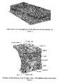
- FIGS. 1 , 2 and 3depict the skin on a finger. The ridges of the fingerprint are formed when rows of papillae are covered by the epidermis. Since the perimeter of the papillae lie at the valleys of the fingerprint, by mapping the papillae structures, a means is available for the virtual reconstruction of the fingerprint image or a portion of the fingerprint image.
- the friction-ridge surface of the skinmay be superficially damaged such that it does not produce a suitable friction-ridge image with traditional imaging systems.
- the inventionmay be used to generate a predicted friction-ridge image corresponding to skin that has not been damaged.
- the inventionmay make use of partial friction-ridge information available from areas that have not been sufficiently damaged, and augment that partial friction-ridge information with information obtained by mapping the papillae that lie beneath the epidermal layer of the skin and form the basis for the missing ridges of the surface.
- the inventionmay be used without partial friction-ridge information to predict the friction-ridge from the dermal papillae.
- FIG. 1is a cross-sectional perspective view of the outer portion of human skin tissue showing layers that make up the tissue. Rows of papillae are shown just beneath the surface; these papillae are covered with an epidermal (outer skin) layer that conforms to the papillae and thus make up the friction-ridges. The area between ridges defines the fingerprint valleys.
- FIG. 2is an enlarged view of a portion of the skin depicted in FIG. 1 .
- FIG. 3is an enlarged view of the skin depicted in FIG. 1 showing part of the epidermal layer removed so that some of the papillae beneath the epidermal layer can be more easily seen.
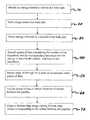
- FIG. 4is a flow chart depicting a method according to the invention.
- FIG. 5is a schematic of a device that may be used to carry out the method outlined in FIG. 4 .
- the inventionmay provide a method by which morphological information is obtained from a portion of skin that is below the epidermis and that information is used predict an image of the friction-ridge surface that would likely result.
- information about the dermal papillaeis obtained, and then that information is used to create an image of the epidermal layer that would likely result from such an arrangement of the dermal papillae.
- the inventionis described using fingerprints, but the invention is not limited to use with fingerprints.
- the dermal papillaesubstantially define the structure of the fingerprint, such that valleys in the dermal papillae correspond to valleys in the fingerprint, and ridges of the dermal papillae correspond to ridges in the fingerprint.
- the fingerprint valleysmay be predicted, thereby allowing for further processing and the eventual reconstruction of a valid fingerprint image.
- an energy transduceris provided 10 .
- the energy transducermay include an energy emitter and a sensor that is sensitive to the emitted energy.
- the energy emitted 20 and sensedmay be ultrasound, radio, visible light, infrared, or magnetic energy.
- other types of energy transducerssuch as capacitance or tomographic imaging, may be used.
- the energy transducermay be aimed at a finger and energy from the transducer may be emitted 20 toward the finger. Some of the energy will be reflected from the papillae back toward the transducer. Energy reflected from the papillae may be detected 30 .
- a piece of datamay be recorded 40 .
- the piece of datamay include the location of the transducer and the time it took the energy to travel to the finger and back to the transducer. In so doing, one piece of data may be created, which corresponds to a particular location on the papillae surface. Many such pieces of data may be obtained 50 , and thereby provide information about the papillae surface.
- the recorded time for each data piecewill depend on the distance between the transducer and the reflection surface. The differences in time and transducer location may be used 60 to determine the relative elevation change from one location on the papillae surface to another location on the papillae surface.
- softwaremay be used 60 to identify valleys between the papillae, and their relative locations with respect to each other.
- the papillae-valleysare, it is possible to predict where the valleys of a fingerprint are likely to be, and thereby create 70 a friction-ridge image of the fingerprint.
- the likely fingerprint-valleysmay be positioned to correspond to the papillae-valleys. In this manner, the information about the papillae surface may be used to create 70 a fingerprint image even though the fingerprint may have been removed from the finger.
- the ridges of the fingerprintmay be predicted.
- a fingerprint ridgemay be placed so as to reside at the mid-point between two predicted valleys.
- the ridgesmay be predicted using the papillae information.
- the peaks of the papillamay be used to predict where the fingerprint ridges are likely to be.
- part of the fingerprintmay be obtained.
- a partial fingerprintmay be obtained, and those areas of the fingerprint that could not be obtained may be identified.
- the papillae informationmay be used, in the manner described above, to provide a predicted friction-ridge pattern corresponding only to those identified areas.
- the predicted patternmay be inserted into the partial fingerprint to provide a more complete image of the fingerprint. In this manner, the time required to generate a fingerprint may be reduced.
- a system 90 for carrying out the inventionis schematically depicted in FIG. 5 .
- That system 90may include an ultrasonic energy transducer 100 , a platen 110 and a data storage device 120 .
- the ultrasound imaging system 90 of FIG. 5 and the corresponding descriptionserves to illustrate the invention, but the invention may be practiced with other systems, including those that use radio waves, high-intensity visible light, infrared light, magnetic energy, capacitance or tomographic imaging.
- a finger 130 to be imagedis rested on the platen 110 .
- the ultrasonic energy transducer 100then may be oriented to direct ultrasonic energy 140 at the finger 130 . While sending and receiving ultrasonic pulses 140 to the finger 130 , the transducer 100 may be moved relative to the finger 130 so as to obtain information about the papillae of the finger 130 . Since the papillae have a different ultrasonic impedance than the physiological structures surrounding the papillae, ultrasonic energy 140 will be reflected from the surfaces of the papillae. The reflected ultrasonic energy 140 may be detected by the transducer 100 and used to determine the location of the papillae surface. It should be noted that other parts of the skin will reflect ultrasonic energy, and through a process known as “range-gating” the reflected energy 140 corresponding to the papillae surface may be identified and distinguished from energy 140 reflected from other skin surfaces.
- the motion of the transducer 100may be substantially parallel to the platen 110 surface on which the finger 130 is rested.
- the location of the transducer 100 when a reflected energy pulse is detectedmay be recorded in the data storage device 120 for future use by a computer 150 .
- the time taken for the ultrasonic pulse to reach the papilla surface and return to the transducer 100 at that locationmay be recorded and correlated with the transducer location. In this manner, one piece of data corresponding to a papilla surface may be obtained.
- the recorded timecorresponds to the distance between the ultrasonic transducer 100 and the reflection surface.
- the recorded timecorresponds to the distance between the ultrasonic transducer 100 and the reflection surface.
- informationmay be obtained about the papillae of the finger 130 , and the varying depths of the papillae surface may be known.
- the varying depths of the papillae surfacemay be used to determine the valleys of the papillae surface.
Landscapes
- Engineering & Computer Science (AREA)
- Human Computer Interaction (AREA)
- Physics & Mathematics (AREA)
- General Physics & Mathematics (AREA)
- Multimedia (AREA)
- Theoretical Computer Science (AREA)
- Measurement Of The Respiration, Hearing Ability, Form, And Blood Characteristics Of Living Organisms (AREA)
Abstract
Description
Claims (41)
Priority Applications (1)
| Application Number | Priority Date | Filing Date | Title |
|---|---|---|---|
| US11/465,398US7421099B2 (en) | 2005-08-17 | 2006-08-17 | Use of papilla mapping to determine a friction-ridge surface |
Applications Claiming Priority (2)
| Application Number | Priority Date | Filing Date | Title |
|---|---|---|---|
| US70889205P | 2005-08-17 | 2005-08-17 | |
| US11/465,398US7421099B2 (en) | 2005-08-17 | 2006-08-17 | Use of papilla mapping to determine a friction-ridge surface |
Publications (2)
| Publication Number | Publication Date |
|---|---|
| US20070076926A1 US20070076926A1 (en) | 2007-04-05 |
| US7421099B2true US7421099B2 (en) | 2008-09-02 |
Family
ID=37758414
Family Applications (1)
| Application Number | Title | Priority Date | Filing Date |
|---|---|---|---|
| US11/465,398Active2026-09-20US7421099B2 (en) | 2005-08-17 | 2006-08-17 | Use of papilla mapping to determine a friction-ridge surface |
Country Status (4)
| Country | Link |
|---|---|
| US (1) | US7421099B2 (en) |
| CA (1) | CA2619733A1 (en) |
| GB (1) | GB2443366B (en) |
| WO (1) | WO2007022379A2 (en) |
Cited By (3)
| Publication number | Priority date | Publication date | Assignee | Title |
|---|---|---|---|---|
| US9582705B2 (en) | 2014-08-31 | 2017-02-28 | Qualcomm Incorporated | Layered filtering for biometric sensors |
| US9665763B2 (en)* | 2014-08-31 | 2017-05-30 | Qualcomm Incorporated | Finger/non-finger determination for biometric sensors |
| US9911184B2 (en) | 2014-08-31 | 2018-03-06 | Qualcomm Incorporated | Air/object determination for biometric sensors |
Families Citing this family (48)
| Publication number | Priority date | Publication date | Assignee | Title |
|---|---|---|---|---|
| US8229184B2 (en)* | 2004-04-16 | 2012-07-24 | Validity Sensors, Inc. | Method and algorithm for accurate finger motion tracking |
| US8165355B2 (en)* | 2006-09-11 | 2012-04-24 | Validity Sensors, Inc. | Method and apparatus for fingerprint motion tracking using an in-line array for use in navigation applications |
| US8358815B2 (en)* | 2004-04-16 | 2013-01-22 | Validity Sensors, Inc. | Method and apparatus for two-dimensional finger motion tracking and control |
| US8131026B2 (en) | 2004-04-16 | 2012-03-06 | Validity Sensors, Inc. | Method and apparatus for fingerprint image reconstruction |
| US8447077B2 (en)* | 2006-09-11 | 2013-05-21 | Validity Sensors, Inc. | Method and apparatus for fingerprint motion tracking using an in-line array |
| US8175345B2 (en) | 2004-04-16 | 2012-05-08 | Validity Sensors, Inc. | Unitized ergonomic two-dimensional fingerprint motion tracking device and method |
| US8077935B2 (en) | 2004-04-23 | 2011-12-13 | Validity Sensors, Inc. | Methods and apparatus for acquiring a swiped fingerprint image |
| DE602005022900D1 (en) | 2004-10-04 | 2010-09-23 | Validity Sensors Inc | FINGERPRINTER CONSTRUCTIONS WITH ONE SUBSTRATE |
| US8107212B2 (en)* | 2007-04-30 | 2012-01-31 | Validity Sensors, Inc. | Apparatus and method for protecting fingerprint sensing circuitry from electrostatic discharge |
| US8290150B2 (en)* | 2007-05-11 | 2012-10-16 | Validity Sensors, Inc. | Method and system for electronically securing an electronic device using physically unclonable functions |
| US20110002461A1 (en)* | 2007-05-11 | 2011-01-06 | Validity Sensors, Inc. | Method and System for Electronically Securing an Electronic Biometric Device Using Physically Unclonable Functions |
| US8276816B2 (en)* | 2007-12-14 | 2012-10-02 | Validity Sensors, Inc. | Smart card system with ergonomic fingerprint sensor and method of using |
| US8204281B2 (en)* | 2007-12-14 | 2012-06-19 | Validity Sensors, Inc. | System and method to remove artifacts from fingerprint sensor scans |
| US8116540B2 (en)* | 2008-04-04 | 2012-02-14 | Validity Sensors, Inc. | Apparatus and method for reducing noise in fingerprint sensing circuits |
| US8005276B2 (en) | 2008-04-04 | 2011-08-23 | Validity Sensors, Inc. | Apparatus and method for reducing parasitic capacitive coupling and noise in fingerprint sensing circuits |
| US8698594B2 (en) | 2008-07-22 | 2014-04-15 | Synaptics Incorporated | System, device and method for securing a user device component by authenticating the user of a biometric sensor by performance of a replication of a portion of an authentication process performed at a remote computing device |
| US20100083000A1 (en)* | 2008-09-16 | 2010-04-01 | Validity Sensors, Inc. | Fingerprint Sensor Device and System with Verification Token and Methods of Using |
| US8391568B2 (en)* | 2008-11-10 | 2013-03-05 | Validity Sensors, Inc. | System and method for improved scanning of fingerprint edges |
| US8278946B2 (en) | 2009-01-15 | 2012-10-02 | Validity Sensors, Inc. | Apparatus and method for detecting finger activity on a fingerprint sensor |
| US8600122B2 (en) | 2009-01-15 | 2013-12-03 | Validity Sensors, Inc. | Apparatus and method for culling substantially redundant data in fingerprint sensing circuits |
| US8374407B2 (en) | 2009-01-28 | 2013-02-12 | Validity Sensors, Inc. | Live finger detection |
| US8799666B2 (en)* | 2009-10-06 | 2014-08-05 | Synaptics Incorporated | Secure user authentication using biometric information |
| US9274553B2 (en) | 2009-10-30 | 2016-03-01 | Synaptics Incorporated | Fingerprint sensor and integratable electronic display |
| US9336428B2 (en) | 2009-10-30 | 2016-05-10 | Synaptics Incorporated | Integrated fingerprint sensor and display |
| US9400911B2 (en) | 2009-10-30 | 2016-07-26 | Synaptics Incorporated | Fingerprint sensor and integratable electronic display |
| US8421890B2 (en) | 2010-01-15 | 2013-04-16 | Picofield Technologies, Inc. | Electronic imager using an impedance sensor grid array and method of making |
| US8866347B2 (en) | 2010-01-15 | 2014-10-21 | Idex Asa | Biometric image sensing |
| US8791792B2 (en) | 2010-01-15 | 2014-07-29 | Idex Asa | Electronic imager using an impedance sensor grid array mounted on or about a switch and method of making |
| US9666635B2 (en) | 2010-02-19 | 2017-05-30 | Synaptics Incorporated | Fingerprint sensing circuit |
| US8716613B2 (en)* | 2010-03-02 | 2014-05-06 | Synaptics Incoporated | Apparatus and method for electrostatic discharge protection |
| US9001040B2 (en) | 2010-06-02 | 2015-04-07 | Synaptics Incorporated | Integrated fingerprint sensor and navigation device |
| US8331096B2 (en) | 2010-08-20 | 2012-12-11 | Validity Sensors, Inc. | Fingerprint acquisition expansion card apparatus |
| US8594393B2 (en) | 2011-01-26 | 2013-11-26 | Validity Sensors | System for and method of image reconstruction with dual line scanner using line counts |
| US8538097B2 (en) | 2011-01-26 | 2013-09-17 | Validity Sensors, Inc. | User input utilizing dual line scanner apparatus and method |
| US9406580B2 (en) | 2011-03-16 | 2016-08-02 | Synaptics Incorporated | Packaging for fingerprint sensors and methods of manufacture |
| US10043052B2 (en) | 2011-10-27 | 2018-08-07 | Synaptics Incorporated | Electronic device packages and methods |
| US9195877B2 (en) | 2011-12-23 | 2015-11-24 | Synaptics Incorporated | Methods and devices for capacitive image sensing |
| US9785299B2 (en) | 2012-01-03 | 2017-10-10 | Synaptics Incorporated | Structures and manufacturing methods for glass covered electronic devices |
| US9268991B2 (en) | 2012-03-27 | 2016-02-23 | Synaptics Incorporated | Method of and system for enrolling and matching biometric data |
| US9137438B2 (en) | 2012-03-27 | 2015-09-15 | Synaptics Incorporated | Biometric object sensor and method |
| US9251329B2 (en) | 2012-03-27 | 2016-02-02 | Synaptics Incorporated | Button depress wakeup and wakeup strategy |
| US9600709B2 (en) | 2012-03-28 | 2017-03-21 | Synaptics Incorporated | Methods and systems for enrolling biometric data |
| US9152838B2 (en) | 2012-03-29 | 2015-10-06 | Synaptics Incorporated | Fingerprint sensor packagings and methods |
| US20130279769A1 (en) | 2012-04-10 | 2013-10-24 | Picofield Technologies Inc. | Biometric Sensing |
| US9665762B2 (en) | 2013-01-11 | 2017-05-30 | Synaptics Incorporated | Tiered wakeup strategy |
| WO2016204176A1 (en) | 2015-06-15 | 2016-12-22 | 日本電気株式会社 | Dermal image information processing device, dermal image information processing method, and program |
| GB201819487D0 (en) | 2018-11-29 | 2019-01-16 | Micromass Ltd | Method of characterising molecules |
| GB201904425D0 (en) | 2019-03-29 | 2019-05-15 | Micromass Ltd | Method of selecting ions |
Citations (5)
| Publication number | Priority date | Publication date | Assignee | Title |
|---|---|---|---|---|
| US5224174A (en)* | 1990-11-07 | 1993-06-29 | Niagara Technology Incorporated | Surface feature mapping using high resolution c-scan ultrasonography |
| US5647364A (en)* | 1995-02-15 | 1997-07-15 | Ultra-Scan Corporation | Ultrasonic biometric imaging and identity verification system |
| US5974886A (en)* | 1997-09-15 | 1999-11-02 | General Electric Company | Method and apparatus for thickness determination in multilayer articles |
| US6993160B2 (en)* | 2000-09-06 | 2006-01-31 | Hitachi, Ltd. | Personal identification device and method |
| US7184580B2 (en)* | 2001-07-24 | 2007-02-27 | Laurence Hamid | Fingerprint scar recognition method and apparatus |
Family Cites Families (2)
| Publication number | Priority date | Publication date | Assignee | Title |
|---|---|---|---|---|
| EP2098977B1 (en)* | 2002-05-09 | 2012-11-21 | Sony Corporation | Method of detecting biological pattern, biological pattern detector, method of biological certificate and biological certificate apparatus |
| US7274807B2 (en)* | 2002-05-30 | 2007-09-25 | Activcard Ireland Limited | Method and apparatus for supporting a biometric registration performed on a card |
- 2006
- 2006-08-17USUS11/465,398patent/US7421099B2/enactiveActive
- 2006-08-17WOPCT/US2006/032180patent/WO2007022379A2/enactiveApplication Filing
- 2006-08-17GBGB0802858Apatent/GB2443366B/ennot_activeExpired - Fee Related
- 2006-08-17CACA002619733Apatent/CA2619733A1/ennot_activeAbandoned
Patent Citations (6)
| Publication number | Priority date | Publication date | Assignee | Title |
|---|---|---|---|---|
| US5224174A (en)* | 1990-11-07 | 1993-06-29 | Niagara Technology Incorporated | Surface feature mapping using high resolution c-scan ultrasonography |
| US5689576A (en)* | 1990-11-07 | 1997-11-18 | Ultra-Scan Corporation | Surface feature mapping using high resolution C-scan ultrasonography |
| US5647364A (en)* | 1995-02-15 | 1997-07-15 | Ultra-Scan Corporation | Ultrasonic biometric imaging and identity verification system |
| US5974886A (en)* | 1997-09-15 | 1999-11-02 | General Electric Company | Method and apparatus for thickness determination in multilayer articles |
| US6993160B2 (en)* | 2000-09-06 | 2006-01-31 | Hitachi, Ltd. | Personal identification device and method |
| US7184580B2 (en)* | 2001-07-24 | 2007-02-27 | Laurence Hamid | Fingerprint scar recognition method and apparatus |
Cited By (3)
| Publication number | Priority date | Publication date | Assignee | Title |
|---|---|---|---|---|
| US9582705B2 (en) | 2014-08-31 | 2017-02-28 | Qualcomm Incorporated | Layered filtering for biometric sensors |
| US9665763B2 (en)* | 2014-08-31 | 2017-05-30 | Qualcomm Incorporated | Finger/non-finger determination for biometric sensors |
| US9911184B2 (en) | 2014-08-31 | 2018-03-06 | Qualcomm Incorporated | Air/object determination for biometric sensors |
Also Published As
| Publication number | Publication date |
|---|---|
| GB2443366B (en) | 2010-11-10 |
| GB0802858D0 (en) | 2008-03-26 |
| US20070076926A1 (en) | 2007-04-05 |
| CA2619733A1 (en) | 2007-02-22 |
| WO2007022379A2 (en) | 2007-02-22 |
| WO2007022379A3 (en) | 2007-07-05 |
| GB2443366A (en) | 2008-04-30 |
Similar Documents
| Publication | Publication Date | Title |
|---|---|---|
| US7421099B2 (en) | Use of papilla mapping to determine a friction-ridge surface | |
| US7708695B2 (en) | Apparatus and method for detecting blood flow | |
| Nixon et al. | Spoof detection schemes | |
| Iula et al. | 3D Ultrasound palm vein pattern for biometric recognition | |
| CN101536384B (en) | Spatial-Spectral Fingerprint Deception Detection | |
| CN100544671C (en) | Method and device for identifying living body | |
| US8180120B2 (en) | Finger sensor using polarized light and associated methods | |
| Kumar | Contactless 3D fingerprint identification | |
| Iula et al. | Experimental evaluation of an ultrasound technique for the biometric recognition of human hand anatomic elements | |
| Iula et al. | Multimodal biometric recognition based on 3d ultrasound palmprint-hand geometry fusion | |
| Wang et al. | A robust and secure palm vessel biometric sensing system based on photoacoustics | |
| Nikam et al. | Local binary pattern and wavelet-based spoof fingerprint detection | |
| CN106473752A (en) | Using method and structure of the weak coherence chromatographic imaging art of holographic field to identification | |
| CN100423018C (en) | Personal identification method and device | |
| Moolla et al. | Optical coherence tomography for fingerprint presentation attack detection | |
| CN1155335C (en) | Method of identifying people | |
| Iula | Optimization and evaluation of a biometric recognition technique based on 3D ultrasound palm vein | |
| Memon et al. | Fingerprint sensors: Liveness detection issue and hardware based solutions | |
| Sadasivuni et al. | Anti-spoofing device for biometric fingerprint scanners | |
| CN105078472B (en) | Physiological characteristic image acquiring device and method | |
| JP3702637B2 (en) | Personal identification device | |
| Maeva et al. | High resolution ultrasonic method for 3D fingerprint recognizable characteristics in biometrics identification | |
| CA2438220A1 (en) | Identification of a person based on ultra-sound scan analyses of hand bone geometry | |
| Meissner et al. | Fingerprint fake detection by optical coherence tomography | |
| CN210691315U (en) | Photoacoustic intensity anti-counterfeiting recognition device based on linear array type mini LED |
Legal Events
| Date | Code | Title | Description |
|---|---|---|---|
| AS | Assignment | Owner name:ULTRA-SCAN CORPORATION, NEW YORK Free format text:ASSIGNMENT OF ASSIGNORS INTEREST;ASSIGNORS:SCHNEIDER, JOHN K.;KITCHENS, JACK C.;REEL/FRAME:018131/0966 Effective date:20060817 | |
| STCF | Information on status: patent grant | Free format text:PATENTED CASE | |
| FPAY | Fee payment | Year of fee payment:4 | |
| FEPP | Fee payment procedure | Free format text:PAT HOLDER NO LONGER CLAIMS SMALL ENTITY STATUS, ENTITY STATUS SET TO UNDISCOUNTED (ORIGINAL EVENT CODE: STOL); ENTITY STATUS OF PATENT OWNER: LARGE ENTITY | |
| AS | Assignment | Owner name:QUALCOMM INCORPORATED, CALIFORNIA Free format text:ASSIGNMENT OF ASSIGNORS INTEREST;ASSIGNOR:ULTRA-SCAN CORPORATION;REEL/FRAME:030416/0069 Effective date:20130507 | |
| FPAY | Fee payment | Year of fee payment:8 | |
| MAFP | Maintenance fee payment | Free format text:PAYMENT OF MAINTENANCE FEE, 12TH YEAR, LARGE ENTITY (ORIGINAL EVENT CODE: M1553); ENTITY STATUS OF PATENT OWNER: LARGE ENTITY Year of fee payment:12 | |
| AS | Assignment | Owner name:NATIONAL SCIENCE FOUNDATION, VIRGINIA Free format text:CONFIRMATORY LICENSE;ASSIGNOR:UNIV OF MARYLAND, COLLEGE PARK;REEL/FRAME:070681/0671 Effective date:20230613 |