US7420774B2 - Housing with a rail shaped to reduce impact damage - Google Patents
Housing with a rail shaped to reduce impact damageDownload PDFInfo
- Publication number
- US7420774B2 US7420774B2US11/238,842US23884205AUS7420774B2US 7420774 B2US7420774 B2US 7420774B2US 23884205 AUS23884205 AUS 23884205AUS 7420774 B2US7420774 B2US 7420774B2
- Authority
- US
- United States
- Prior art keywords
- impact
- flexible web
- rail
- rim
- offset
- Prior art date
- Legal status (The legal status is an assumption and is not a legal conclusion. Google has not performed a legal analysis and makes no representation as to the accuracy of the status listed.)
- Expired - Fee Related, expires
Links
Images


Classifications
- G—PHYSICS
- G11—INFORMATION STORAGE
- G11B—INFORMATION STORAGE BASED ON RELATIVE MOVEMENT BETWEEN RECORD CARRIER AND TRANSDUCER
- G11B33/00—Constructional parts, details or accessories not provided for in the other groups of this subclass
- G11B33/02—Cabinets; Cases; Stands; Disposition of apparatus therein or thereon
- G11B33/08—Insulation or absorption of undesired vibrations or sounds
Definitions
- the present inventionrelates generally to protecting delicate mechanical components from damage due to mechanical shock, and more particularly, but not by way of limitation, to protecting discs and heads in disc drives from shock damage.
- Disc drivesinclude delicate mechanical components that can be damaged by shock if a disc drive is dropped on a hard surface or object during manufacturing, testing or installing the disc drive in a computer.
- disc drivesinclude read/write heads that are mounted on delicate mechanical suspensions to access disc surfaces. When there is mechanical shock or vibration, the read/write heads can bounce on the disc surfaces. The bouncing can damage the disc surfaces, the read/write heads or both.
- disc drivesinclude side rails that protrude from a bottom side of a disc drive housing. It is found that damage to discs or heads from a head slap event is often traceable to shocks that occur when a rail impacts a hard surface. The head temporarily separates from the disc and then slaps back on the disc.
- a method and apparatusare needed to reduce head slap or other damage to mechanical components in a housing with side rails when the side rails impact a hard surface.
- Embodiments of the present inventionprovide solutions to these and other problems, and offer other advantages over the prior art.
- a housingcomprising a base.
- the baseincludes a baseplate and a rail.
- the railprojects outwardly to an impact rim that extends along a bottom edge of the rail.
- the railincludes a flexible web that couples the impact rim to the baseplate.
- a projecting contact surface on the impact rimis laterally offset from at least one bending axis through the flexible web.
- An impact to the contact surfaceis offset from the bending axis by a moment arm.
- the housingcomprises a scanning mechanism supported on the base and susceptible to impact damage.
- the bending of the flexible webbuffers the scanning mechanism from the impact.
- the scanning mechanismcomprises a read/write head and a storage disc.
- FIGS. 1-3illustrate a disc drive housing with impact rims.
- FIG. 4illustrates a portion of a housing with an impact rim.
- FIG. 5illustrates an enlarged view of an impact rim.
- FIGS. 6-9illustrate alternative embodiments of impact rims.
- bending of a flexible web in a outwardly projecting housing railbuffers a scanning mechanism in the housing from an impact.
- a projecting contact rimis laterally offset from a bending axis by a moment arm and converts a portion of the impact into bending motion.
- the impact to the scanning mechanismis reduced.
- a disc drive housingis provided with rails on opposite sides, and when the disc drive housing is dropped on either rail and strikes a surface, head slap damage is greatly reduced.
- FIGS. 1-3schematically illustrate a disc drive housing 200 that has rails 230 , 232 that are shaped to mitigate mechanical damage from impact.
- FIG. 1illustrates an end view of the disc drive housing 200 .
- FIG. 2illustrates a bottom view of the disc drive housing 200 .
- FIG. 3illustrates a side view of the disc drive housing 200 .
- the disc drive housing 200includes a base 202 used for mounting various disc drive components, and a cover 203 .
- the base 202includes a baseplate 204 that is generally planar, but includes a through hole 206 for mounting a spindle motor 208 .
- the baseplate 204also includes a mounting pad 210 for mounting a hub 211 ( FIG. 2 ) of a rotary moving voice coil actuator arm 212 ( FIG. 2 ).
- the mounting pad 210(which is illustrated in FIGS. 1-2 with a stippled surface) is a generally round cylindrical protrusion from the baseplate 204 .
- the mounting pad 210typically has a central bore along an axis 209 for receiving a pivot shaft (not illustrated) for the actuator arm 212 .
- a read/write head 214is suspended on an end of the actuator arm 212 .
- the read/write head 214is supported by a delicate mechanical suspension over a media surface of a disc 216 that is spun by the spindle motor 208 .
- the read/write head 214 and the disc 216are subject to head slap damage from shock when the disc drive housing 200 is dropped on a surface such as surface 217 or otherwise impacts another object at one of the rails 230 , 232 .
- a printed circuit board (PCB) 220is mounted on a bottom side of the disc drive housing 200 .
- the spindle motor 208projects through a round hole 222 in the printed circuit board 220 .
- the mounting pad 210projects through a round hole 224 in the printed circuit board 220 .
- rails 230 , 232project outwardly (and preferably downwardly) from the baseplate 204 to form impact rims 234 , 236 ( FIGS. 1-2 ) that extend along the bottom edges of the rails 230 , 232 .
- the impact rims 234 , 236 and rails 230 , 232are shaped as described below in connection with examples in FIGS. 4-9 to mitigate impact damage to the read/write head 214 and the disc 216 .
- the rails 230 , 232include grooves 290 , 292 which are cut into the rails 230 , 232 to form flexible webs 280 , 282 .
- the disc drive housing 200is secured, typically by screws at mounting holes 250 , 252 to a computer assembly.
- the disc drive housing 200may be dropped or set on surfaces so that there is a substantial impact to one of the impact rims 234 or 236 .
- the impacts at the impact rims 234 , 236are transmitted to the flexible webs 280 , 282 .
- the flexible webs 280 , 282are arranged in a mechanical relationship with the impact rims 234 , 236 such that impacts transmitted to the read/write head 214 and to the disc 216 are greatly attenuated, avoiding head slap damage to the read/write head 214 and the disc 216 .
- the impact rims 234 , 236have projecting contact surfaces that are laterally offset from a bending axis (or bending axes) that run through the flexible web. A generally vertical impact to a contact surface is offset from the bending axis by a moment arm.
- the offsetting of the impact from the bending axiscauses a portion of the impact to be converted from translational motion to bending motion.
- the bending motionis dissipated by the bending of the flexible web, and less impact reaches delicate components such as the read/write head 214 and the disc 216 .
- Details of the mechanical and geometric arrangement of the flexible webs 280 , 282 and the impact rims 234 , 236 via one or more moment armsare described in more detail below in connection with enlarged views of rails in FIGS. 4-5 .
- FIG. 4illustrates a portion of a housing 400 .
- the housing 400comprises a base 402 that includes a baseplate 404 and a rail 406 .
- the rail 406projects outwardly to an impact rim 408 that extends along a bottom edge 410 of the rail 406 .
- the rail 406includes a flexible web 412 (identified by a stippled appearance) that couples the impact rim 408 to the baseplate 404 .
- a projecting contact surface 414 on the impact rim 408is laterally offset by a distance 416 from a bending axis 418 that passes through the flexible web 412 .
- a generally vertical impact 420(illustrated as an arrow) to the contact surface 414 is offset from the bending axis 418 by a moment arm 422 .
- the bending axis 418runs lengthwise along the entire length of the rail 406 or, alternatively, the rail 406 can be provided with one or more vertical slots (not illustrated) that divide the rail 406 into shorter rail sections.
- the term “moment arm” as used in this applicationrefers to a perpendicular distance from a line along which an impact is applied to a bending axis. In the example shown in FIG. 4 , there is a moment arm 422 that is perpendicular to a line 424 along which impact 420 is applied. The moment arm extends from the line 424 to the bending axis 418 .
- the force of the impact 420 multiplied by the length of the moment arm 422calculates a bending force (torsional moment) about the bending axis 418 .
- the torsional momenttends to bend the flexible web 412 , dissipating impact force so that the full impact force does not reach a scanning mechanism 430 that is mounted adjacent the baseplate 404 .
- the flexible web 412bends to absorb the generally vertical impact 420 .
- the flexible web 412is formed of material, such as aluminum or plastic resin, that acts as a spring and a damper.
- the flexible web 412is preferably formed as a seamless part of the rail 406 .
- the impact rim 408preferably has a recessed surface 432 that is shielded from impact by the projecting contact 414 .
- the base 402preferably comprises metal or plastic resin.
- the mechanical dimensions of the flexible web 412are preferably selected such that deformations of the flexible web 412 due to impact forces are generally in a elastic range of the metal or plastic resin material used.
- the flexible web 412preferably rebounds from deflections due to impacts, so that the impact absorption feature can be used repeatedly.
- the base 402can be provided with an additional rail or rail similar to rail 406 .
- the flexible web 412is adjacent a notch 434 that extends along a length of the rail 406 .
- the scanning mechanism 430is supported on the base 402 and is susceptible to impact damage.
- the bending of the flexible web 412buffers the scanning mechanism 430 from the generally vertical impact 420 .
- the scanning mechanism 430comprises data storage media 440 and a transducer 442 suspended adjacent the data storage media 440 .
- the transducer 442can comprise a magnetic head, an optical head, a magneto-optical head or a ferroelectric contact probe array.
- the transducer 442may be in physical contact with the storage media 440 or suspended a small distance above the storage media 440 .
- the transducer 442can be a magnetic head that is either parked or flying.
- the transducer 442can be ferroelectric contact probe array that contacts ferroelectric storage media, or it can be a contact probe array that is retracted from the ferroelectric storage media. There is a potential for mechanical damage in each of these conditions.
- FIG. 5illustrates an enlarged view of a rail 506 that includes an impact rim 508 comparable to those shown in FIG. 4 .
- the impact rim 508has a contact surface 514 that can receive impacts 520 , 521 from different angles that deviate from a vertical direction.
- a flexible web 512(identified by a stippled appearance) extends along a vertical distance 550 of the rail 506 . Bending of the rail 506 can take place at a number of bending axes along the length of the flexible web 512 , including AXIS 1 and AXIS 2 .
- IMPACT 1 at 520is aligned with AXIS 2 , and thus IMPACT 1 has a zero moment arm relative to AXIS 2 and can't generate significant bending about AXIS 2 .
- IMPACT 1is not aligned with AXIS 1 and thus has a non-zero moment arm (MOMENT ARM 1 ) relative to AXIS 1 .
- IMPACT 1can thus generate significant bending about AXIS 1 .
- IMPACT 2 at 521is aligned with AXIS 1 , and thus IMPACT 2 has a zero moment arm relative to AXIS 1 and can't generate significant bending about AXIS 1 .
- IMPACT 2is not aligned with AXIS 2 and thus has a non-zero moment arm (MOMENT ARM 2 ) relative to AXIS 2 .
- IMPACT 2can thus generate significant bending about AXIS 2 .
- the flexible web 512extends along a vertical axis range 550 to provide multiple bending axes that accommodate an angular range of non-vertical impacts.
- the impact to the contact surface 514can come from any generally vertical angle and have a non-zero moment arm relative to at least one bending axis so that bending always takes place at some bending axis.
- the arrangementis thus not sensitive to impact angle.
- the projecting contact on a pair of railscan be arranged to provide an impact shielding angle of more than 180 degrees to protect a circuit card and other components between the rails.
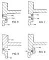
- FIGS. 6-9illustrate alternative embodiments of impact rims.
- FIG. 6illustrates an embodiment with an impact rim 602 and a flexible web 604 as describe above in connection with FIG. 4 combined with a second flexible web 606 .
- the second flexible web 606provides some additional buffering of generally lateral impacts to the side of the impact rim 602 .
- FIG. 7illustrates an embodiment with an impact rim 702 , a flexible web 704 as described above in connection with FIG. 4 combined with a second flexible web 706 that provide a wider vertical range of bending axis locations and increased bendability without exceeding an elastic limit of the materials.
- FIG. 8illustrates an embodiment with an impact rim 802 , and a flexible web 804 .
- the impact rim 802is on an inner side of a rail 810
- the flexible web 804is on an outer side of the rail 810 .
- the impact rim 802 and the flexible web 804are on opposite sides of the rail 810 , and non-zero moment arms are provided over a wide range axes and of angles as described above in connection with FIG. 5 .
- FIG. 9illustrates an embodiment in which a bead of mechanical damping material, such as silicone rubber, is applied adjacent a flexible web 904 to provide mechanical damping of bending, providing further attenuation of impacts.
- a bead of mechanical damping materialsuch as silicone rubber
Landscapes
- Moving Of Heads (AREA)
Abstract
Description
Claims (18)
Priority Applications (1)
| Application Number | Priority Date | Filing Date | Title |
|---|---|---|---|
| US11/238,842US7420774B2 (en) | 2005-09-29 | 2005-09-29 | Housing with a rail shaped to reduce impact damage |
Applications Claiming Priority (1)
| Application Number | Priority Date | Filing Date | Title |
|---|---|---|---|
| US11/238,842US7420774B2 (en) | 2005-09-29 | 2005-09-29 | Housing with a rail shaped to reduce impact damage |
Publications (2)
| Publication Number | Publication Date |
|---|---|
| US20070070596A1 US20070070596A1 (en) | 2007-03-29 |
| US7420774B2true US7420774B2 (en) | 2008-09-02 |
Family
ID=37893592
Family Applications (1)
| Application Number | Title | Priority Date | Filing Date |
|---|---|---|---|
| US11/238,842Expired - Fee RelatedUS7420774B2 (en) | 2005-09-29 | 2005-09-29 | Housing with a rail shaped to reduce impact damage |
Country Status (1)
| Country | Link |
|---|---|
| US (1) | US7420774B2 (en) |
Cited By (7)
| Publication number | Priority date | Publication date | Assignee | Title |
|---|---|---|---|---|
| US20070290282A1 (en)* | 2006-06-15 | 2007-12-20 | Nanochip, Inc. | Bonded chip assembly with a micro-mover for microelectromechanical systems |
| US20070291623A1 (en)* | 2006-06-15 | 2007-12-20 | Nanochip, Inc. | Cantilever with control of vertical and lateral position of contact probe tip |
| US7626846B2 (en) | 2007-07-16 | 2009-12-01 | Nanochip, Inc. | Method and media for improving ferroelectric domain stability in an information storage device |
| US20100085863A1 (en)* | 2008-10-07 | 2010-04-08 | Nanochip, Inc. | Retuning of ferroelectric media built-in-bias |
| US20110072445A1 (en)* | 2009-09-24 | 2011-03-24 | Dell Products, Lp | Optical Disk Drive with Reduced Noise |
| US20130033780A1 (en)* | 2011-08-05 | 2013-02-07 | Samsung Electro-Mechanics Co., Ltd. | Base for motor and hard disk drive including the same |
| US8477449B2 (en)* | 2011-11-03 | 2013-07-02 | Samsung Electro-Mechanics Co., Ltd. | Base for motor and hard disk drive including the same |
Families Citing this family (3)
| Publication number | Priority date | Publication date | Assignee | Title |
|---|---|---|---|---|
| US20080232228A1 (en)* | 2007-03-20 | 2008-09-25 | Nanochip, Inc. | Systems and methods of writing and reading a ferro-electric media with a probe tip |
| US7838066B2 (en)* | 2007-12-20 | 2010-11-23 | Seagate Technology Llc | Ferroelectric media with robust servo marks and storage areas with low leakage current |
| KR20130015889A (en)* | 2011-08-05 | 2013-02-14 | 삼성전기주식회사 | Base for motor and hard disk drive including the same |
Citations (35)
| Publication number | Priority date | Publication date | Assignee | Title |
|---|---|---|---|---|
| US5394306A (en) | 1993-09-07 | 1995-02-28 | Norand Corporation | Shock absorbent packaging apparatus |
| US5552946A (en) | 1994-09-30 | 1996-09-03 | International Business Machines Corporation | Compliant rail for shock protection of a PCMCIA DASD |
| US5703734A (en) | 1994-10-12 | 1997-12-30 | International Business Machines Corporation | Disc drive having an integral gasket and continuous outer perimeter shock bumper |
| US5717575A (en)* | 1995-08-09 | 1998-02-10 | Digital Equipment Corporation | Board mounting system with self guiding interengagement |
| US5751514A (en) | 1993-09-09 | 1998-05-12 | Western Digital Corporation | Intelligent disk drive having spring contacts on a board assembly for connecting to exterior-facing electrical contacts coupled to a spindle motor |
| US5757580A (en) | 1996-11-27 | 1998-05-26 | Seagate Technology, Inc. | Constrain layer damping of a disc drive printed wiring assembly |
| US5965249A (en) | 1997-08-07 | 1999-10-12 | Gore Enterprise Holdings, Inc. | Vibration damping composite material |
| US5982580A (en) | 1995-07-18 | 1999-11-09 | Seagate Technology, Inc. | Acoustic noise control in a disc drive |
| US6021041A (en) | 1997-06-09 | 2000-02-01 | Dell U.S.A., L.P | Tuned shock absorbing system for portable computer hard disc drives |
| US6023392A (en) | 1997-01-30 | 2000-02-08 | Samsung Electronics Co., Ltd. | Hard disk drive cover having improved structural and production characteristics |
| US6022224A (en) | 1998-07-22 | 2000-02-08 | International Business Machines Corporation | Shock mount connector for head disk assembly |
| US6052255A (en) | 1994-10-06 | 2000-04-18 | Hitachi, Ltd. | Magnetic disk unit having anti-impact arrangement |
| US6064567A (en) | 1997-12-29 | 2000-05-16 | Compaq Computer Corporation | Portable computer hard disk drive mounting apparatus and methods |
| US6078498A (en) | 1997-11-21 | 2000-06-20 | Seagate Technology, Inc. | Low sway space isolation chassis adapter for a disc drive |
| US6252768B1 (en) | 1999-06-09 | 2001-06-26 | Twinhead International Corp. | Shock-absorbing device for notebook computer module |
| US6272011B1 (en) | 1999-12-07 | 2001-08-07 | Star Chen | Hard diskdrive mobile rack |
| US20010012175A1 (en) | 1998-10-08 | 2001-08-09 | Kelly Williams | Shock isolator for a hard disk drive |
| US6275353B1 (en) | 1999-08-03 | 2001-08-14 | Seagate Technology Llc | Housing for a disc drive having cantilevered base slot to reduce mechanical shock damage |
| US6288866B1 (en) | 1999-11-19 | 2001-09-11 | Western Digital Technologies, Inc. | Disk drive including a vibration damping system having a compressible foam and mass damper fixed adjacent to the outer surface of a printed circuit board for reducing noise and vibration |
| US20020057522A1 (en) | 1999-05-07 | 2002-05-16 | Seagate Technology Llc | Disc drive protective cover to improve shock robustness |
| US6392982B1 (en) | 1998-09-29 | 2002-05-21 | Mitsubishi Denki Kabushiki Kaisha | Corner part reinforcing device of disc device chassis |
| US6417985B1 (en) | 1998-11-18 | 2002-07-09 | Nec Corporation | Magnetic disk drive |
| US6473263B2 (en) | 1998-11-17 | 2002-10-29 | Samsung Electronics Co., Ltd. | Cover structure of hard disk drive with air damping layer |
| US6473270B1 (en) | 1999-08-25 | 2002-10-29 | Seagate Technologies Llc | Actuator shock snubber |
| US6487039B1 (en) | 1999-06-24 | 2002-11-26 | Seagate Technology Llc | Disc-drive mounting method and apparatus to reduce noise |
| US6498719B1 (en) | 1999-12-10 | 2002-12-24 | Dell Usa, L.P. | Apparatus and method for reducing impact-induced shock and vibration in a portable computer |
| US20030011974A1 (en) | 2001-07-10 | 2003-01-16 | Curlee James Don | Mounting rail for hard disk drive |
| US6545865B2 (en) | 2001-07-13 | 2003-04-08 | International Business Machines Corporation | Shock mount for a device packaged in a portable cartridge |
| US6543738B2 (en) | 2001-07-20 | 2003-04-08 | International Business Machines Corporation | Integral flush shock mount |
| US6583950B2 (en) | 1997-02-27 | 2003-06-24 | Hitachi, Ltd. | Information storage and retrieval device provided with shock-absorbing mechanism |
| US6597533B1 (en) | 1999-06-04 | 2003-07-22 | Teac Corporation | Recording medium loading device |
| US6822858B2 (en) | 1999-11-18 | 2004-11-23 | Siemens Energy & Automation, Inc. | Disk drive mounting system for absorbing shock and vibration in a machining environment |
| US20050111134A1 (en) | 2003-11-22 | 2005-05-26 | Samsung Electronics Co., Ltd. | Disk drive having anti-shock structure |
| US7012805B2 (en) | 2003-07-16 | 2006-03-14 | Olixir Technologies | Ruggedized host module |
| US7218474B2 (en)* | 2004-06-10 | 2007-05-15 | Seagate Technology, Llc | Assembly rail corners shaped to reduce shock |
- 2005
- 2005-09-29USUS11/238,842patent/US7420774B2/ennot_activeExpired - Fee Related
Patent Citations (36)
| Publication number | Priority date | Publication date | Assignee | Title |
|---|---|---|---|---|
| US5394306A (en) | 1993-09-07 | 1995-02-28 | Norand Corporation | Shock absorbent packaging apparatus |
| US5751514A (en) | 1993-09-09 | 1998-05-12 | Western Digital Corporation | Intelligent disk drive having spring contacts on a board assembly for connecting to exterior-facing electrical contacts coupled to a spindle motor |
| US5552946A (en) | 1994-09-30 | 1996-09-03 | International Business Machines Corporation | Compliant rail for shock protection of a PCMCIA DASD |
| US6052255A (en) | 1994-10-06 | 2000-04-18 | Hitachi, Ltd. | Magnetic disk unit having anti-impact arrangement |
| US5703734A (en) | 1994-10-12 | 1997-12-30 | International Business Machines Corporation | Disc drive having an integral gasket and continuous outer perimeter shock bumper |
| US5760998A (en) | 1994-10-12 | 1998-06-02 | International Business Machines Corporation | Disk drive with rotatable bumper blocks |
| US5982580A (en) | 1995-07-18 | 1999-11-09 | Seagate Technology, Inc. | Acoustic noise control in a disc drive |
| US5717575A (en)* | 1995-08-09 | 1998-02-10 | Digital Equipment Corporation | Board mounting system with self guiding interengagement |
| US5757580A (en) | 1996-11-27 | 1998-05-26 | Seagate Technology, Inc. | Constrain layer damping of a disc drive printed wiring assembly |
| US6023392A (en) | 1997-01-30 | 2000-02-08 | Samsung Electronics Co., Ltd. | Hard disk drive cover having improved structural and production characteristics |
| US6583950B2 (en) | 1997-02-27 | 2003-06-24 | Hitachi, Ltd. | Information storage and retrieval device provided with shock-absorbing mechanism |
| US6021041A (en) | 1997-06-09 | 2000-02-01 | Dell U.S.A., L.P | Tuned shock absorbing system for portable computer hard disc drives |
| US5965249A (en) | 1997-08-07 | 1999-10-12 | Gore Enterprise Holdings, Inc. | Vibration damping composite material |
| US6078498A (en) | 1997-11-21 | 2000-06-20 | Seagate Technology, Inc. | Low sway space isolation chassis adapter for a disc drive |
| US6064567A (en) | 1997-12-29 | 2000-05-16 | Compaq Computer Corporation | Portable computer hard disk drive mounting apparatus and methods |
| US6022224A (en) | 1998-07-22 | 2000-02-08 | International Business Machines Corporation | Shock mount connector for head disk assembly |
| US6392982B1 (en) | 1998-09-29 | 2002-05-21 | Mitsubishi Denki Kabushiki Kaisha | Corner part reinforcing device of disc device chassis |
| US20010012175A1 (en) | 1998-10-08 | 2001-08-09 | Kelly Williams | Shock isolator for a hard disk drive |
| US6473263B2 (en) | 1998-11-17 | 2002-10-29 | Samsung Electronics Co., Ltd. | Cover structure of hard disk drive with air damping layer |
| US6417985B1 (en) | 1998-11-18 | 2002-07-09 | Nec Corporation | Magnetic disk drive |
| US20020057522A1 (en) | 1999-05-07 | 2002-05-16 | Seagate Technology Llc | Disc drive protective cover to improve shock robustness |
| US6597533B1 (en) | 1999-06-04 | 2003-07-22 | Teac Corporation | Recording medium loading device |
| US6252768B1 (en) | 1999-06-09 | 2001-06-26 | Twinhead International Corp. | Shock-absorbing device for notebook computer module |
| US6487039B1 (en) | 1999-06-24 | 2002-11-26 | Seagate Technology Llc | Disc-drive mounting method and apparatus to reduce noise |
| US6275353B1 (en) | 1999-08-03 | 2001-08-14 | Seagate Technology Llc | Housing for a disc drive having cantilevered base slot to reduce mechanical shock damage |
| US6473270B1 (en) | 1999-08-25 | 2002-10-29 | Seagate Technologies Llc | Actuator shock snubber |
| US6822858B2 (en) | 1999-11-18 | 2004-11-23 | Siemens Energy & Automation, Inc. | Disk drive mounting system for absorbing shock and vibration in a machining environment |
| US6288866B1 (en) | 1999-11-19 | 2001-09-11 | Western Digital Technologies, Inc. | Disk drive including a vibration damping system having a compressible foam and mass damper fixed adjacent to the outer surface of a printed circuit board for reducing noise and vibration |
| US6272011B1 (en) | 1999-12-07 | 2001-08-07 | Star Chen | Hard diskdrive mobile rack |
| US6498719B1 (en) | 1999-12-10 | 2002-12-24 | Dell Usa, L.P. | Apparatus and method for reducing impact-induced shock and vibration in a portable computer |
| US20030011974A1 (en) | 2001-07-10 | 2003-01-16 | Curlee James Don | Mounting rail for hard disk drive |
| US6545865B2 (en) | 2001-07-13 | 2003-04-08 | International Business Machines Corporation | Shock mount for a device packaged in a portable cartridge |
| US6543738B2 (en) | 2001-07-20 | 2003-04-08 | International Business Machines Corporation | Integral flush shock mount |
| US7012805B2 (en) | 2003-07-16 | 2006-03-14 | Olixir Technologies | Ruggedized host module |
| US20050111134A1 (en) | 2003-11-22 | 2005-05-26 | Samsung Electronics Co., Ltd. | Disk drive having anti-shock structure |
| US7218474B2 (en)* | 2004-06-10 | 2007-05-15 | Seagate Technology, Llc | Assembly rail corners shaped to reduce shock |
Cited By (11)
| Publication number | Priority date | Publication date | Assignee | Title |
|---|---|---|---|---|
| US20070290282A1 (en)* | 2006-06-15 | 2007-12-20 | Nanochip, Inc. | Bonded chip assembly with a micro-mover for microelectromechanical systems |
| US20070291623A1 (en)* | 2006-06-15 | 2007-12-20 | Nanochip, Inc. | Cantilever with control of vertical and lateral position of contact probe tip |
| US7626846B2 (en) | 2007-07-16 | 2009-12-01 | Nanochip, Inc. | Method and media for improving ferroelectric domain stability in an information storage device |
| US20100085863A1 (en)* | 2008-10-07 | 2010-04-08 | Nanochip, Inc. | Retuning of ferroelectric media built-in-bias |
| US20110072445A1 (en)* | 2009-09-24 | 2011-03-24 | Dell Products, Lp | Optical Disk Drive with Reduced Noise |
| US8724307B2 (en)* | 2009-09-24 | 2014-05-13 | Dell Products, Lp | Optical disk drive with reduced noise |
| US20130033780A1 (en)* | 2011-08-05 | 2013-02-07 | Samsung Electro-Mechanics Co., Ltd. | Base for motor and hard disk drive including the same |
| US8780495B2 (en)* | 2011-08-05 | 2014-07-15 | Samsung Electro-Mechanics Co., Ltd. | Base for motor and hard disk drive including the same |
| KR101477331B1 (en)* | 2011-08-05 | 2014-12-30 | 삼성전기주식회사 | Base for motor and hard disk drive including the same |
| US8477449B2 (en)* | 2011-11-03 | 2013-07-02 | Samsung Electro-Mechanics Co., Ltd. | Base for motor and hard disk drive including the same |
| US8755144B2 (en) | 2011-11-03 | 2014-06-17 | Samsung Electro-Mechanics Co., Ltd. | Base for motor and hard disk drive including the same |
Also Published As
| Publication number | Publication date |
|---|---|
| US20070070596A1 (en) | 2007-03-29 |
Similar Documents
| Publication | Publication Date | Title |
|---|---|---|
| US7248467B2 (en) | Apparatus for a shock absorber that allows a disk drive to move with respect to the chassis of a computer system | |
| EP0929069B1 (en) | Suspension assembly | |
| US6735043B2 (en) | Disc drive protective cover to improve shock robustness | |
| KR100753074B1 (en) | Head suspension and disk drive unit | |
| US7755865B2 (en) | Vibration reducing head suspension mechanism for a magnetic disc unit | |
| US7420774B2 (en) | Housing with a rail shaped to reduce impact damage | |
| KR19990023199A (en) | Disk drive unit | |
| KR20020027579A (en) | Actuator shock snubber | |
| US6704161B1 (en) | Shock protection skin bumper for a hard disk drive | |
| KR100442872B1 (en) | Supporting apparatus for actuator of hard disk drive | |
| CN101192434B (en) | Universal joint with asymmetric dynamic characteristics | |
| US7064931B2 (en) | Disc drive suspension optimized for preload bend damper | |
| US5815350A (en) | Head disk assembly with actuator latch vibration damper | |
| US20100290154A1 (en) | Hard disk drive | |
| JPH11162086A (en) | Magnetic head support device | |
| JP3945760B2 (en) | Magnetic head device, magnetic head support mechanism, and magnetic recording device | |
| US6477017B2 (en) | Disk drive and head suspension unit | |
| US7304823B2 (en) | Suspension for head slider having higher resistance to vibration | |
| KR100362582B1 (en) | Method and device for limiting head movement within a hard disk drive | |
| US7218474B2 (en) | Assembly rail corners shaped to reduce shock | |
| KR100350684B1 (en) | Device for reducing damage due to head slap within a hard disk drive | |
| US6215627B1 (en) | Suspension assembly gimbal load beam stiffener | |
| US20030231432A1 (en) | Windage, shock and low mass conventional suspension design | |
| US7559132B2 (en) | Method for manufacturing a shock absorber that allows a disk drive to move with respect to the chassis of a computer system | |
| KR100346171B1 (en) | Shock absorber-limiter to constrain head movement within a hard disk drive |
Legal Events
| Date | Code | Title | Description |
|---|---|---|---|
| AS | Assignment | Owner name:SEAGATE TECHNOLOGY LLC, CALIFORNIA Free format text:ASSIGNMENT OF ASSIGNORS INTEREST;ASSIGNOR:SOORELL, JASON ALLEN;REEL/FRAME:017491/0854 Effective date:20051114 | |
| AS | Assignment | Owner name:SEAGATE TECHNOLOGY LLC, CALIFORNIA Free format text:ASSIGNMENT OF ASSIGNORS INTEREST;ASSIGNORS:SIEVERS, RYAN ANDREW;SORRELL, JASON ALLEN;REEL/FRAME:017839/0282;SIGNING DATES FROM 20051114 TO 20060419 | |
| AS | Assignment | Owner name:WELLS FARGO BANK, NATIONAL ASSOCIATION, AS COLLATERAL AGENT AND SECOND PRIORITY REPRESENTATIVE, CALIFORNIA Free format text:SECURITY AGREEMENT;ASSIGNORS:MAXTOR CORPORATION;SEAGATE TECHNOLOGY LLC;SEAGATE TECHNOLOGY INTERNATIONAL;REEL/FRAME:022757/0017 Effective date:20090507 Owner name:JPMORGAN CHASE BANK, N.A., AS ADMINISTRATIVE AGENT AND FIRST PRIORITY REPRESENTATIVE, NEW YORK Free format text:SECURITY AGREEMENT;ASSIGNORS:MAXTOR CORPORATION;SEAGATE TECHNOLOGY LLC;SEAGATE TECHNOLOGY INTERNATIONAL;REEL/FRAME:022757/0017 Effective date:20090507 Owner name:JPMORGAN CHASE BANK, N.A., AS ADMINISTRATIVE AGENT Free format text:SECURITY AGREEMENT;ASSIGNORS:MAXTOR CORPORATION;SEAGATE TECHNOLOGY LLC;SEAGATE TECHNOLOGY INTERNATIONAL;REEL/FRAME:022757/0017 Effective date:20090507 Owner name:WELLS FARGO BANK, NATIONAL ASSOCIATION, AS COLLATE Free format text:SECURITY AGREEMENT;ASSIGNORS:MAXTOR CORPORATION;SEAGATE TECHNOLOGY LLC;SEAGATE TECHNOLOGY INTERNATIONAL;REEL/FRAME:022757/0017 Effective date:20090507 | |
| AS | Assignment | Owner name:SEAGATE TECHNOLOGY HDD HOLDINGS, CALIFORNIA Free format text:RELEASE;ASSIGNOR:JPMORGAN CHASE BANK, N.A., AS ADMINISTRATIVE AGENT;REEL/FRAME:025662/0001 Effective date:20110114 Owner name:SEAGATE TECHNOLOGY INTERNATIONAL, CALIFORNIA Free format text:RELEASE;ASSIGNOR:JPMORGAN CHASE BANK, N.A., AS ADMINISTRATIVE AGENT;REEL/FRAME:025662/0001 Effective date:20110114 Owner name:SEAGATE TECHNOLOGY LLC, CALIFORNIA Free format text:RELEASE;ASSIGNOR:JPMORGAN CHASE BANK, N.A., AS ADMINISTRATIVE AGENT;REEL/FRAME:025662/0001 Effective date:20110114 Owner name:MAXTOR CORPORATION, CALIFORNIA Free format text:RELEASE;ASSIGNOR:JPMORGAN CHASE BANK, N.A., AS ADMINISTRATIVE AGENT;REEL/FRAME:025662/0001 Effective date:20110114 | |
| AS | Assignment | Owner name:THE BANK OF NOVA SCOTIA, AS ADMINISTRATIVE AGENT, CANADA Free format text:SECURITY AGREEMENT;ASSIGNOR:SEAGATE TECHNOLOGY LLC;REEL/FRAME:026010/0350 Effective date:20110118 Owner name:THE BANK OF NOVA SCOTIA, AS ADMINISTRATIVE AGENT, Free format text:SECURITY AGREEMENT;ASSIGNOR:SEAGATE TECHNOLOGY LLC;REEL/FRAME:026010/0350 Effective date:20110118 | |
| FPAY | Fee payment | Year of fee payment:4 | |
| AS | Assignment | Owner name:SEAGATE TECHNOLOGY LLC, CALIFORNIA Free format text:TERMINATION AND RELEASE OF SECURITY INTEREST IN PATENT RIGHTS;ASSIGNOR:WELLS FARGO BANK, NATIONAL ASSOCIATION, AS COLLATERAL AGENT AND SECOND PRIORITY REPRESENTATIVE;REEL/FRAME:030833/0001 Effective date:20130312 Owner name:SEAGATE TECHNOLOGY INTERNATIONAL, CAYMAN ISLANDS Free format text:TERMINATION AND RELEASE OF SECURITY INTEREST IN PATENT RIGHTS;ASSIGNOR:WELLS FARGO BANK, NATIONAL ASSOCIATION, AS COLLATERAL AGENT AND SECOND PRIORITY REPRESENTATIVE;REEL/FRAME:030833/0001 Effective date:20130312 Owner name:SEAGATE TECHNOLOGY US HOLDINGS, INC., CALIFORNIA Free format text:TERMINATION AND RELEASE OF SECURITY INTEREST IN PATENT RIGHTS;ASSIGNOR:WELLS FARGO BANK, NATIONAL ASSOCIATION, AS COLLATERAL AGENT AND SECOND PRIORITY REPRESENTATIVE;REEL/FRAME:030833/0001 Effective date:20130312 Owner name:EVAULT INC. (F/K/A I365 INC.), CALIFORNIA Free format text:TERMINATION AND RELEASE OF SECURITY INTEREST IN PATENT RIGHTS;ASSIGNOR:WELLS FARGO BANK, NATIONAL ASSOCIATION, AS COLLATERAL AGENT AND SECOND PRIORITY REPRESENTATIVE;REEL/FRAME:030833/0001 Effective date:20130312 | |
| REMI | Maintenance fee reminder mailed | ||
| LAPS | Lapse for failure to pay maintenance fees | ||
| STCH | Information on status: patent discontinuation | Free format text:PATENT EXPIRED DUE TO NONPAYMENT OF MAINTENANCE FEES UNDER 37 CFR 1.362 | |
| FP | Lapsed due to failure to pay maintenance fee | Effective date:20160902 | |
| AS | Assignment | Owner name:SEAGATE TECHNOLOGY PUBLIC LIMITED COMPANY, CALIFORNIA Free format text:RELEASE BY SECURED PARTY;ASSIGNOR:THE BANK OF NOVA SCOTIA;REEL/FRAME:072193/0001 Effective date:20250303 Owner name:SEAGATE TECHNOLOGY, CALIFORNIA Free format text:RELEASE BY SECURED PARTY;ASSIGNOR:THE BANK OF NOVA SCOTIA;REEL/FRAME:072193/0001 Effective date:20250303 Owner name:SEAGATE TECHNOLOGY HDD HOLDINGS, CALIFORNIA Free format text:RELEASE BY SECURED PARTY;ASSIGNOR:THE BANK OF NOVA SCOTIA;REEL/FRAME:072193/0001 Effective date:20250303 Owner name:I365 INC., CALIFORNIA Free format text:RELEASE BY SECURED PARTY;ASSIGNOR:THE BANK OF NOVA SCOTIA;REEL/FRAME:072193/0001 Effective date:20250303 Owner name:SEAGATE TECHNOLOGY LLC, CALIFORNIA Free format text:RELEASE BY SECURED PARTY;ASSIGNOR:THE BANK OF NOVA SCOTIA;REEL/FRAME:072193/0001 Effective date:20250303 Owner name:SEAGATE TECHNOLOGY INTERNATIONAL, CAYMAN ISLANDS Free format text:RELEASE BY SECURED PARTY;ASSIGNOR:THE BANK OF NOVA SCOTIA;REEL/FRAME:072193/0001 Effective date:20250303 Owner name:SEAGATE HDD CAYMAN, CAYMAN ISLANDS Free format text:RELEASE BY SECURED PARTY;ASSIGNOR:THE BANK OF NOVA SCOTIA;REEL/FRAME:072193/0001 Effective date:20250303 Owner name:SEAGATE TECHNOLOGY (US) HOLDINGS, INC., CALIFORNIA Free format text:RELEASE BY SECURED PARTY;ASSIGNOR:THE BANK OF NOVA SCOTIA;REEL/FRAME:072193/0001 Effective date:20250303 |