US7419488B2 - Electrosurgical probe with movable return electrode and methods related thereto - Google Patents
Electrosurgical probe with movable return electrode and methods related theretoDownload PDFInfo
- Publication number
- US7419488B2 US7419488B2US11/028,709US2870905AUS7419488B2US 7419488 B2US7419488 B2US 7419488B2US 2870905 AUS2870905 AUS 2870905AUS 7419488 B2US7419488 B2US 7419488B2
- Authority
- US
- United States
- Prior art keywords
- electrode
- probe
- tissue
- return electrode
- active
- Prior art date
- Legal status (The legal status is an assumption and is not a legal conclusion. Google has not performed a legal analysis and makes no representation as to the accuracy of the status listed.)
- Expired - Fee Related, expires
Links
Images


Classifications
- A—HUMAN NECESSITIES
- A61—MEDICAL OR VETERINARY SCIENCE; HYGIENE
- A61B—DIAGNOSIS; SURGERY; IDENTIFICATION
- A61B18/00—Surgical instruments, devices or methods for transferring non-mechanical forms of energy to or from the body
- A61B18/04—Surgical instruments, devices or methods for transferring non-mechanical forms of energy to or from the body by heating
- A61B18/12—Surgical instruments, devices or methods for transferring non-mechanical forms of energy to or from the body by heating by passing a current through the tissue to be heated, e.g. high-frequency current
- A61B18/14—Probes or electrodes therefor
- A61B18/1402—Probes for open surgery
- A—HUMAN NECESSITIES
- A61—MEDICAL OR VETERINARY SCIENCE; HYGIENE
- A61B—DIAGNOSIS; SURGERY; IDENTIFICATION
- A61B18/00—Surgical instruments, devices or methods for transferring non-mechanical forms of energy to or from the body
- A61B18/04—Surgical instruments, devices or methods for transferring non-mechanical forms of energy to or from the body by heating
- A61B18/12—Surgical instruments, devices or methods for transferring non-mechanical forms of energy to or from the body by heating by passing a current through the tissue to be heated, e.g. high-frequency current
- A61B18/14—Probes or electrodes therefor
- A61B18/1482—Probes or electrodes therefor having a long rigid shaft for accessing the inner body transcutaneously in minimal invasive surgery, e.g. laparoscopy
- A—HUMAN NECESSITIES
- A61—MEDICAL OR VETERINARY SCIENCE; HYGIENE
- A61B—DIAGNOSIS; SURGERY; IDENTIFICATION
- A61B18/00—Surgical instruments, devices or methods for transferring non-mechanical forms of energy to or from the body
- A61B18/04—Surgical instruments, devices or methods for transferring non-mechanical forms of energy to or from the body by heating
- A61B18/12—Surgical instruments, devices or methods for transferring non-mechanical forms of energy to or from the body by heating by passing a current through the tissue to be heated, e.g. high-frequency current
- A61B18/14—Probes or electrodes therefor
- A61B18/149—Probes or electrodes therefor bow shaped or with rotatable body at cantilever end, e.g. for resectoscopes, or coagulating rollers
- A—HUMAN NECESSITIES
- A61—MEDICAL OR VETERINARY SCIENCE; HYGIENE
- A61B—DIAGNOSIS; SURGERY; IDENTIFICATION
- A61B18/00—Surgical instruments, devices or methods for transferring non-mechanical forms of energy to or from the body
- A61B18/04—Surgical instruments, devices or methods for transferring non-mechanical forms of energy to or from the body by heating
- A61B18/12—Surgical instruments, devices or methods for transferring non-mechanical forms of energy to or from the body by heating by passing a current through the tissue to be heated, e.g. high-frequency current
- A61B18/14—Probes or electrodes therefor
- A61B18/1492—Probes or electrodes therefor having a flexible, catheter-like structure, e.g. for heart ablation
- A—HUMAN NECESSITIES
- A61—MEDICAL OR VETERINARY SCIENCE; HYGIENE
- A61B—DIAGNOSIS; SURGERY; IDENTIFICATION
- A61B18/00—Surgical instruments, devices or methods for transferring non-mechanical forms of energy to or from the body
- A61B18/04—Surgical instruments, devices or methods for transferring non-mechanical forms of energy to or from the body by heating
- A61B18/042—Surgical instruments, devices or methods for transferring non-mechanical forms of energy to or from the body by heating using additional gas becoming plasma
- A—HUMAN NECESSITIES
- A61—MEDICAL OR VETERINARY SCIENCE; HYGIENE
- A61B—DIAGNOSIS; SURGERY; IDENTIFICATION
- A61B18/00—Surgical instruments, devices or methods for transferring non-mechanical forms of energy to or from the body
- A61B18/04—Surgical instruments, devices or methods for transferring non-mechanical forms of energy to or from the body by heating
- A61B18/12—Surgical instruments, devices or methods for transferring non-mechanical forms of energy to or from the body by heating by passing a current through the tissue to be heated, e.g. high-frequency current
- A61B18/1206—Generators therefor
- A—HUMAN NECESSITIES
- A61—MEDICAL OR VETERINARY SCIENCE; HYGIENE
- A61B—DIAGNOSIS; SURGERY; IDENTIFICATION
- A61B18/00—Surgical instruments, devices or methods for transferring non-mechanical forms of energy to or from the body
- A61B18/04—Surgical instruments, devices or methods for transferring non-mechanical forms of energy to or from the body by heating
- A61B18/12—Surgical instruments, devices or methods for transferring non-mechanical forms of energy to or from the body by heating by passing a current through the tissue to be heated, e.g. high-frequency current
- A61B18/14—Probes or electrodes therefor
- A61B18/148—Probes or electrodes therefor having a short, rigid shaft for accessing the inner body transcutaneously, e.g. for neurosurgery or arthroscopy
- A—HUMAN NECESSITIES
- A61—MEDICAL OR VETERINARY SCIENCE; HYGIENE
- A61B—DIAGNOSIS; SURGERY; IDENTIFICATION
- A61B18/00—Surgical instruments, devices or methods for transferring non-mechanical forms of energy to or from the body
- A61B18/04—Surgical instruments, devices or methods for transferring non-mechanical forms of energy to or from the body by heating
- A61B18/12—Surgical instruments, devices or methods for transferring non-mechanical forms of energy to or from the body by heating by passing a current through the tissue to be heated, e.g. high-frequency current
- A61B18/14—Probes or electrodes therefor
- A61B18/1485—Probes or electrodes therefor having a short rigid shaft for accessing the inner body through natural openings
- A—HUMAN NECESSITIES
- A61—MEDICAL OR VETERINARY SCIENCE; HYGIENE
- A61B—DIAGNOSIS; SURGERY; IDENTIFICATION
- A61B17/00—Surgical instruments, devices or methods
- A61B2017/00017—Electrical control of surgical instruments
- A61B2017/00022—Sensing or detecting at the treatment site
- A61B2017/00026—Conductivity or impedance, e.g. of tissue
- A—HUMAN NECESSITIES
- A61—MEDICAL OR VETERINARY SCIENCE; HYGIENE
- A61B—DIAGNOSIS; SURGERY; IDENTIFICATION
- A61B17/00—Surgical instruments, devices or methods
- A61B2017/00017—Electrical control of surgical instruments
- A61B2017/00022—Sensing or detecting at the treatment site
- A61B2017/00084—Temperature
- A61B2017/00101—Temperature using an array of thermosensors
- A—HUMAN NECESSITIES
- A61—MEDICAL OR VETERINARY SCIENCE; HYGIENE
- A61B—DIAGNOSIS; SURGERY; IDENTIFICATION
- A61B17/00—Surgical instruments, devices or methods
- A61B17/00234—Surgical instruments, devices or methods for minimally invasive surgery
- A61B2017/00238—Type of minimally invasive operation
- A61B2017/00243—Type of minimally invasive operation cardiac
- A61B2017/00247—Making holes in the wall of the heart, e.g. laser Myocardial revascularization
- A—HUMAN NECESSITIES
- A61—MEDICAL OR VETERINARY SCIENCE; HYGIENE
- A61B—DIAGNOSIS; SURGERY; IDENTIFICATION
- A61B18/00—Surgical instruments, devices or methods for transferring non-mechanical forms of energy to or from the body
- A61B2018/00005—Cooling or heating of the probe or tissue immediately surrounding the probe
- A61B2018/00011—Cooling or heating of the probe or tissue immediately surrounding the probe with fluids
- A61B2018/00029—Cooling or heating of the probe or tissue immediately surrounding the probe with fluids open
- A—HUMAN NECESSITIES
- A61—MEDICAL OR VETERINARY SCIENCE; HYGIENE
- A61B—DIAGNOSIS; SURGERY; IDENTIFICATION
- A61B18/00—Surgical instruments, devices or methods for transferring non-mechanical forms of energy to or from the body
- A61B2018/00053—Mechanical features of the instrument of device
- A61B2018/00059—Material properties
- A61B2018/00071—Electrical conductivity
- A61B2018/00083—Electrical conductivity low, i.e. electrically insulating
- A—HUMAN NECESSITIES
- A61—MEDICAL OR VETERINARY SCIENCE; HYGIENE
- A61B—DIAGNOSIS; SURGERY; IDENTIFICATION
- A61B18/00—Surgical instruments, devices or methods for transferring non-mechanical forms of energy to or from the body
- A61B2018/00053—Mechanical features of the instrument of device
- A61B2018/00107—Coatings on the energy applicator
- A61B2018/00119—Coatings on the energy applicator with metal oxide nitride
- A—HUMAN NECESSITIES
- A61—MEDICAL OR VETERINARY SCIENCE; HYGIENE
- A61B—DIAGNOSIS; SURGERY; IDENTIFICATION
- A61B18/00—Surgical instruments, devices or methods for transferring non-mechanical forms of energy to or from the body
- A61B2018/00053—Mechanical features of the instrument of device
- A61B2018/00107—Coatings on the energy applicator
- A61B2018/00148—Coatings on the energy applicator with metal
- A—HUMAN NECESSITIES
- A61—MEDICAL OR VETERINARY SCIENCE; HYGIENE
- A61B—DIAGNOSIS; SURGERY; IDENTIFICATION
- A61B18/00—Surgical instruments, devices or methods for transferring non-mechanical forms of energy to or from the body
- A61B2018/00053—Mechanical features of the instrument of device
- A61B2018/0016—Energy applicators arranged in a two- or three dimensional array
- A—HUMAN NECESSITIES
- A61—MEDICAL OR VETERINARY SCIENCE; HYGIENE
- A61B—DIAGNOSIS; SURGERY; IDENTIFICATION
- A61B18/00—Surgical instruments, devices or methods for transferring non-mechanical forms of energy to or from the body
- A61B2018/00053—Mechanical features of the instrument of device
- A61B2018/00172—Connectors and adapters therefor
- A61B2018/00178—Electrical connectors
- A—HUMAN NECESSITIES
- A61—MEDICAL OR VETERINARY SCIENCE; HYGIENE
- A61B—DIAGNOSIS; SURGERY; IDENTIFICATION
- A61B18/00—Surgical instruments, devices or methods for transferring non-mechanical forms of energy to or from the body
- A61B2018/00315—Surgical instruments, devices or methods for transferring non-mechanical forms of energy to or from the body for treatment of particular body parts
- A61B2018/00321—Head or parts thereof
- A61B2018/00327—Ear, nose or throat
- A—HUMAN NECESSITIES
- A61—MEDICAL OR VETERINARY SCIENCE; HYGIENE
- A61B—DIAGNOSIS; SURGERY; IDENTIFICATION
- A61B18/00—Surgical instruments, devices or methods for transferring non-mechanical forms of energy to or from the body
- A61B2018/00315—Surgical instruments, devices or methods for transferring non-mechanical forms of energy to or from the body for treatment of particular body parts
- A61B2018/00345—Vascular system
- A61B2018/00351—Heart
- A61B2018/00392—Transmyocardial revascularisation
- A—HUMAN NECESSITIES
- A61—MEDICAL OR VETERINARY SCIENCE; HYGIENE
- A61B—DIAGNOSIS; SURGERY; IDENTIFICATION
- A61B18/00—Surgical instruments, devices or methods for transferring non-mechanical forms of energy to or from the body
- A61B2018/00315—Surgical instruments, devices or methods for transferring non-mechanical forms of energy to or from the body for treatment of particular body parts
- A61B2018/00345—Vascular system
- A61B2018/00404—Blood vessels other than those in or around the heart
- A—HUMAN NECESSITIES
- A61—MEDICAL OR VETERINARY SCIENCE; HYGIENE
- A61B—DIAGNOSIS; SURGERY; IDENTIFICATION
- A61B18/00—Surgical instruments, devices or methods for transferring non-mechanical forms of energy to or from the body
- A61B2018/00315—Surgical instruments, devices or methods for transferring non-mechanical forms of energy to or from the body for treatment of particular body parts
- A61B2018/00452—Skin
- A61B2018/0047—Upper parts of the skin, e.g. skin peeling or treatment of wrinkles
- A—HUMAN NECESSITIES
- A61—MEDICAL OR VETERINARY SCIENCE; HYGIENE
- A61B—DIAGNOSIS; SURGERY; IDENTIFICATION
- A61B18/00—Surgical instruments, devices or methods for transferring non-mechanical forms of energy to or from the body
- A61B2018/00315—Surgical instruments, devices or methods for transferring non-mechanical forms of energy to or from the body for treatment of particular body parts
- A61B2018/00452—Skin
- A61B2018/00476—Hair follicles
- A—HUMAN NECESSITIES
- A61—MEDICAL OR VETERINARY SCIENCE; HYGIENE
- A61B—DIAGNOSIS; SURGERY; IDENTIFICATION
- A61B18/00—Surgical instruments, devices or methods for transferring non-mechanical forms of energy to or from the body
- A61B2018/00315—Surgical instruments, devices or methods for transferring non-mechanical forms of energy to or from the body for treatment of particular body parts
- A61B2018/00505—Urinary tract
- A—HUMAN NECESSITIES
- A61—MEDICAL OR VETERINARY SCIENCE; HYGIENE
- A61B—DIAGNOSIS; SURGERY; IDENTIFICATION
- A61B18/00—Surgical instruments, devices or methods for transferring non-mechanical forms of energy to or from the body
- A61B2018/00571—Surgical instruments, devices or methods for transferring non-mechanical forms of energy to or from the body for achieving a particular surgical effect
- A61B2018/00577—Ablation
- A61B2018/00583—Coblation, i.e. ablation using a cold plasma
- A—HUMAN NECESSITIES
- A61—MEDICAL OR VETERINARY SCIENCE; HYGIENE
- A61B—DIAGNOSIS; SURGERY; IDENTIFICATION
- A61B18/00—Surgical instruments, devices or methods for transferring non-mechanical forms of energy to or from the body
- A61B2018/00571—Surgical instruments, devices or methods for transferring non-mechanical forms of energy to or from the body for achieving a particular surgical effect
- A61B2018/00601—Cutting
- A—HUMAN NECESSITIES
- A61—MEDICAL OR VETERINARY SCIENCE; HYGIENE
- A61B—DIAGNOSIS; SURGERY; IDENTIFICATION
- A61B18/00—Surgical instruments, devices or methods for transferring non-mechanical forms of energy to or from the body
- A61B2018/00571—Surgical instruments, devices or methods for transferring non-mechanical forms of energy to or from the body for achieving a particular surgical effect
- A61B2018/00625—Vaporization
- A—HUMAN NECESSITIES
- A61—MEDICAL OR VETERINARY SCIENCE; HYGIENE
- A61B—DIAGNOSIS; SURGERY; IDENTIFICATION
- A61B18/00—Surgical instruments, devices or methods for transferring non-mechanical forms of energy to or from the body
- A61B2018/00636—Sensing and controlling the application of energy
- A61B2018/00666—Sensing and controlling the application of energy using a threshold value
- A61B2018/00678—Sensing and controlling the application of energy using a threshold value upper
- A—HUMAN NECESSITIES
- A61—MEDICAL OR VETERINARY SCIENCE; HYGIENE
- A61B—DIAGNOSIS; SURGERY; IDENTIFICATION
- A61B18/00—Surgical instruments, devices or methods for transferring non-mechanical forms of energy to or from the body
- A61B2018/00636—Sensing and controlling the application of energy
- A61B2018/00696—Controlled or regulated parameters
- A61B2018/00702—Power or energy
- A—HUMAN NECESSITIES
- A61—MEDICAL OR VETERINARY SCIENCE; HYGIENE
- A61B—DIAGNOSIS; SURGERY; IDENTIFICATION
- A61B18/00—Surgical instruments, devices or methods for transferring non-mechanical forms of energy to or from the body
- A61B2018/00636—Sensing and controlling the application of energy
- A61B2018/00696—Controlled or regulated parameters
- A61B2018/00726—Duty cycle
- A—HUMAN NECESSITIES
- A61—MEDICAL OR VETERINARY SCIENCE; HYGIENE
- A61B—DIAGNOSIS; SURGERY; IDENTIFICATION
- A61B18/00—Surgical instruments, devices or methods for transferring non-mechanical forms of energy to or from the body
- A61B2018/00636—Sensing and controlling the application of energy
- A61B2018/00773—Sensed parameters
- A61B2018/00791—Temperature
- A61B2018/00797—Temperature measured by multiple temperature sensors
- A—HUMAN NECESSITIES
- A61—MEDICAL OR VETERINARY SCIENCE; HYGIENE
- A61B—DIAGNOSIS; SURGERY; IDENTIFICATION
- A61B18/00—Surgical instruments, devices or methods for transferring non-mechanical forms of energy to or from the body
- A61B2018/00636—Sensing and controlling the application of energy
- A61B2018/00773—Sensed parameters
- A61B2018/00791—Temperature
- A61B2018/00815—Temperature measured by a thermistor
- A—HUMAN NECESSITIES
- A61—MEDICAL OR VETERINARY SCIENCE; HYGIENE
- A61B—DIAGNOSIS; SURGERY; IDENTIFICATION
- A61B18/00—Surgical instruments, devices or methods for transferring non-mechanical forms of energy to or from the body
- A61B2018/00636—Sensing and controlling the application of energy
- A61B2018/00773—Sensed parameters
- A61B2018/00791—Temperature
- A61B2018/00821—Temperature measured by a thermocouple
- A—HUMAN NECESSITIES
- A61—MEDICAL OR VETERINARY SCIENCE; HYGIENE
- A61B—DIAGNOSIS; SURGERY; IDENTIFICATION
- A61B18/00—Surgical instruments, devices or methods for transferring non-mechanical forms of energy to or from the body
- A61B2018/00636—Sensing and controlling the application of energy
- A61B2018/00773—Sensed parameters
- A61B2018/00827—Current
- A—HUMAN NECESSITIES
- A61—MEDICAL OR VETERINARY SCIENCE; HYGIENE
- A61B—DIAGNOSIS; SURGERY; IDENTIFICATION
- A61B18/00—Surgical instruments, devices or methods for transferring non-mechanical forms of energy to or from the body
- A61B2018/00636—Sensing and controlling the application of energy
- A61B2018/00773—Sensed parameters
- A61B2018/00875—Resistance or impedance
- A—HUMAN NECESSITIES
- A61—MEDICAL OR VETERINARY SCIENCE; HYGIENE
- A61B—DIAGNOSIS; SURGERY; IDENTIFICATION
- A61B18/00—Surgical instruments, devices or methods for transferring non-mechanical forms of energy to or from the body
- A61B18/04—Surgical instruments, devices or methods for transferring non-mechanical forms of energy to or from the body by heating
- A61B18/12—Surgical instruments, devices or methods for transferring non-mechanical forms of energy to or from the body by heating by passing a current through the tissue to be heated, e.g. high-frequency current
- A61B18/1206—Generators therefor
- A61B2018/1213—Generators therefor creating an arc
- A—HUMAN NECESSITIES
- A61—MEDICAL OR VETERINARY SCIENCE; HYGIENE
- A61B—DIAGNOSIS; SURGERY; IDENTIFICATION
- A61B18/00—Surgical instruments, devices or methods for transferring non-mechanical forms of energy to or from the body
- A61B18/04—Surgical instruments, devices or methods for transferring non-mechanical forms of energy to or from the body by heating
- A61B18/12—Surgical instruments, devices or methods for transferring non-mechanical forms of energy to or from the body by heating by passing a current through the tissue to be heated, e.g. high-frequency current
- A61B18/1206—Generators therefor
- A61B2018/124—Generators therefor switching the output to different electrodes, e.g. sequentially
- A—HUMAN NECESSITIES
- A61—MEDICAL OR VETERINARY SCIENCE; HYGIENE
- A61B—DIAGNOSIS; SURGERY; IDENTIFICATION
- A61B18/00—Surgical instruments, devices or methods for transferring non-mechanical forms of energy to or from the body
- A61B18/04—Surgical instruments, devices or methods for transferring non-mechanical forms of energy to or from the body by heating
- A61B18/12—Surgical instruments, devices or methods for transferring non-mechanical forms of energy to or from the body by heating by passing a current through the tissue to be heated, e.g. high-frequency current
- A61B18/1206—Generators therefor
- A61B2018/1246—Generators therefor characterised by the output polarity
- A61B2018/1253—Generators therefor characterised by the output polarity monopolar
- A—HUMAN NECESSITIES
- A61—MEDICAL OR VETERINARY SCIENCE; HYGIENE
- A61B—DIAGNOSIS; SURGERY; IDENTIFICATION
- A61B18/00—Surgical instruments, devices or methods for transferring non-mechanical forms of energy to or from the body
- A61B18/04—Surgical instruments, devices or methods for transferring non-mechanical forms of energy to or from the body by heating
- A61B18/12—Surgical instruments, devices or methods for transferring non-mechanical forms of energy to or from the body by heating by passing a current through the tissue to be heated, e.g. high-frequency current
- A61B18/1206—Generators therefor
- A61B2018/1246—Generators therefor characterised by the output polarity
- A61B2018/126—Generators therefor characterised by the output polarity bipolar
- A—HUMAN NECESSITIES
- A61—MEDICAL OR VETERINARY SCIENCE; HYGIENE
- A61B—DIAGNOSIS; SURGERY; IDENTIFICATION
- A61B18/00—Surgical instruments, devices or methods for transferring non-mechanical forms of energy to or from the body
- A61B18/04—Surgical instruments, devices or methods for transferring non-mechanical forms of energy to or from the body by heating
- A61B18/12—Surgical instruments, devices or methods for transferring non-mechanical forms of energy to or from the body by heating by passing a current through the tissue to be heated, e.g. high-frequency current
- A61B18/1206—Generators therefor
- A61B2018/1273—Generators therefor including multiple generators in one device
- A—HUMAN NECESSITIES
- A61—MEDICAL OR VETERINARY SCIENCE; HYGIENE
- A61B—DIAGNOSIS; SURGERY; IDENTIFICATION
- A61B18/00—Surgical instruments, devices or methods for transferring non-mechanical forms of energy to or from the body
- A61B18/04—Surgical instruments, devices or methods for transferring non-mechanical forms of energy to or from the body by heating
- A61B18/12—Surgical instruments, devices or methods for transferring non-mechanical forms of energy to or from the body by heating by passing a current through the tissue to be heated, e.g. high-frequency current
- A61B18/14—Probes or electrodes therefor
- A61B2018/1405—Electrodes having a specific shape
- A61B2018/1412—Blade
- A—HUMAN NECESSITIES
- A61—MEDICAL OR VETERINARY SCIENCE; HYGIENE
- A61B—DIAGNOSIS; SURGERY; IDENTIFICATION
- A61B18/00—Surgical instruments, devices or methods for transferring non-mechanical forms of energy to or from the body
- A61B18/04—Surgical instruments, devices or methods for transferring non-mechanical forms of energy to or from the body by heating
- A61B18/12—Surgical instruments, devices or methods for transferring non-mechanical forms of energy to or from the body by heating by passing a current through the tissue to be heated, e.g. high-frequency current
- A61B18/14—Probes or electrodes therefor
- A61B2018/1405—Electrodes having a specific shape
- A61B2018/1422—Hook
- A—HUMAN NECESSITIES
- A61—MEDICAL OR VETERINARY SCIENCE; HYGIENE
- A61B—DIAGNOSIS; SURGERY; IDENTIFICATION
- A61B18/00—Surgical instruments, devices or methods for transferring non-mechanical forms of energy to or from the body
- A61B18/04—Surgical instruments, devices or methods for transferring non-mechanical forms of energy to or from the body by heating
- A61B18/12—Surgical instruments, devices or methods for transferring non-mechanical forms of energy to or from the body by heating by passing a current through the tissue to be heated, e.g. high-frequency current
- A61B18/14—Probes or electrodes therefor
- A61B2018/1467—Probes or electrodes therefor using more than two electrodes on a single probe
- A—HUMAN NECESSITIES
- A61—MEDICAL OR VETERINARY SCIENCE; HYGIENE
- A61B—DIAGNOSIS; SURGERY; IDENTIFICATION
- A61B18/00—Surgical instruments, devices or methods for transferring non-mechanical forms of energy to or from the body
- A61B18/04—Surgical instruments, devices or methods for transferring non-mechanical forms of energy to or from the body by heating
- A61B18/12—Surgical instruments, devices or methods for transferring non-mechanical forms of energy to or from the body by heating by passing a current through the tissue to be heated, e.g. high-frequency current
- A61B18/14—Probes or electrodes therefor
- A61B2018/1472—Probes or electrodes therefor for use with liquid electrolyte, e.g. virtual electrodes
- A—HUMAN NECESSITIES
- A61—MEDICAL OR VETERINARY SCIENCE; HYGIENE
- A61B—DIAGNOSIS; SURGERY; IDENTIFICATION
- A61B18/00—Surgical instruments, devices or methods for transferring non-mechanical forms of energy to or from the body
- A61B18/04—Surgical instruments, devices or methods for transferring non-mechanical forms of energy to or from the body by heating
- A61B18/12—Surgical instruments, devices or methods for transferring non-mechanical forms of energy to or from the body by heating by passing a current through the tissue to be heated, e.g. high-frequency current
- A61B18/14—Probes or electrodes therefor
- A61B18/16—Indifferent or passive electrodes for grounding
- A61B2018/162—Indifferent or passive electrodes for grounding located on the probe body
- A—HUMAN NECESSITIES
- A61—MEDICAL OR VETERINARY SCIENCE; HYGIENE
- A61B—DIAGNOSIS; SURGERY; IDENTIFICATION
- A61B18/00—Surgical instruments, devices or methods for transferring non-mechanical forms of energy to or from the body
- A61B18/04—Surgical instruments, devices or methods for transferring non-mechanical forms of energy to or from the body by heating
- A61B18/12—Surgical instruments, devices or methods for transferring non-mechanical forms of energy to or from the body by heating by passing a current through the tissue to be heated, e.g. high-frequency current
- A61B18/14—Probes or electrodes therefor
- A61B18/16—Indifferent or passive electrodes for grounding
- A61B2018/165—Multiple indifferent electrodes
- A—HUMAN NECESSITIES
- A61—MEDICAL OR VETERINARY SCIENCE; HYGIENE
- A61B—DIAGNOSIS; SURGERY; IDENTIFICATION
- A61B2218/00—Details of surgical instruments, devices or methods for transferring non-mechanical forms of energy to or from the body
- A61B2218/001—Details of surgical instruments, devices or methods for transferring non-mechanical forms of energy to or from the body having means for irrigation and/or aspiration of substances to and/or from the surgical site
- A61B2218/002—Irrigation
- A61B2218/003—Irrigation using a spray or a foam
- A—HUMAN NECESSITIES
- A61—MEDICAL OR VETERINARY SCIENCE; HYGIENE
- A61B—DIAGNOSIS; SURGERY; IDENTIFICATION
- A61B2218/00—Details of surgical instruments, devices or methods for transferring non-mechanical forms of energy to or from the body
- A61B2218/001—Details of surgical instruments, devices or methods for transferring non-mechanical forms of energy to or from the body having means for irrigation and/or aspiration of substances to and/or from the surgical site
- A61B2218/007—Aspiration
- A—HUMAN NECESSITIES
- A61—MEDICAL OR VETERINARY SCIENCE; HYGIENE
- A61F—FILTERS IMPLANTABLE INTO BLOOD VESSELS; PROSTHESES; DEVICES PROVIDING PATENCY TO, OR PREVENTING COLLAPSING OF, TUBULAR STRUCTURES OF THE BODY, e.g. STENTS; ORTHOPAEDIC, NURSING OR CONTRACEPTIVE DEVICES; FOMENTATION; TREATMENT OR PROTECTION OF EYES OR EARS; BANDAGES, DRESSINGS OR ABSORBENT PADS; FIRST-AID KITS
- A61F2/00—Filters implantable into blood vessels; Prostheses, i.e. artificial substitutes or replacements for parts of the body; Appliances for connecting them with the body; Devices providing patency to, or preventing collapsing of, tubular structures of the body, e.g. stents
- A61F2/02—Prostheses implantable into the body
- A61F2/24—Heart valves ; Vascular valves, e.g. venous valves; Heart implants, e.g. passive devices for improving the function of the native valve or the heart muscle; Transmyocardial revascularisation [TMR] devices; Valves implantable in the body
- A61F2/2493—Transmyocardial revascularisation [TMR] devices
Definitions
- the present inventiongenerally relates to electrosurgical systems and methods for ablating, severing, dissecting, contracting, or otherwise modifying target tissues or organs.
- the present inventionalso relates to electrosurgical apparatus and methods for clamping, compressing, coagulating, welding, occluding, and severing blood vessels during surgical procedures.
- the inventionrelates more particularly to electrosurgical apparatus and methods for modifying a tissue or organ, wherein the apparatus includes an active electrode, a first return electrode fixed with respect to the active electrode, and a second return electrode movable with respect to the active electrode.
- the present inventionstill further relates to a laparoscopic electrosurgical probe adapted for cutting, coagulation, and blunt dissection of tissue during laparoscopic procedures.
- Conventional electrosurgical instruments and techniquesare widely used in surgical procedures because they generally reduce patient bleeding and trauma associated with cutting operations, as compared with mechanical cutting and the like.
- Conventional electrosurgical proceduresmay be classified as operating in monopolar or bipolar mode.
- Monopolar techniquesrely on external grounding of the patient, where the surgical device defines only a single electrode pole.
- Bipolar deviceshave two electrodes for the application of current between their surfaces.
- Conventional electrosurgical devices and proceduressuffer from a number of disadvantages.
- conventional electrosurgical cutting devicestypically operate by creating a voltage difference between the active electrode and the target tissue, causing an electrical arc to form across the physical gap between the electrode and the tissue. At the point of contact of the electric arcs with the tissue, rapid tissue heating occurs due to high current density between the electrode and the tissue.
- This high current densitycauses cellular fluids to rapidly vaporize into steam, thereby producing a “cutting effect” along the pathway of localized tissue heating.
- the tissueis parted along the pathway of evaporated cellular fluids to rapidly vaporize into steam, thereby producing a “cutting effect” along the pathway of localized tissue heating.
- the tissueis parted along the pathway of evaporated cellular fluid, inducing undesirable collateral tissue damage in regions surrounding the target tissue.
- monopolar electrosurgical devicesgenerally direct electric current along a defined path from the exposed or active electrode through the patient's body to the return electrode, the latter externally attached to a suitable location on the patient. This creates the potential danger that the electric current will flow through undefined paths in the patient's body, thereby increasing the risk of unwanted electrical stimulation to portions of the patient's body.
- the defined path through the patient's bodyhas a relatively high electrical impedance, large voltage differences must typically be applied between the return and active electrodes in order to generate a current suitable for ablation or cutting of the target tissue. This current, however, may inadvertently flow along body paths having less impedance than the defined electrical path, which will substantially increase the current flowing through these paths, possibly causing damage to or destroying surrounding tissue.
- conventional electrosurgical methodsare generally ineffective for ablating certain types of tissue, and in certain types of environments within the body.
- loose or elastic connective tissuesuch as the synovial tissue in joints
- conventional electrosurgical instrumentsbecause the flexible tissue tends to move away from the instrument when it is brought against this tissue.
- conventional techniquesrely mainly on conducting current through the tissue, they are not effective when the instrument cannot be brought adjacent to, or in contact with, the elastic tissue for a sufficient period of time to energize the electrode and conduct current through the tissue.
- the present inventiongenerally provides systems, apparatus, and methods for selectively applying electrical energy to cut, incise, ablate, or otherwise modify a tissue or organ of a patient.
- apparatus and methods of the inventionare useful for electrosurgically cutting and resecting tissue, and for dissecting, coagulating, occluding, and severing veins, arteries or other hollow organs of a patient during a broad range of surgical procedures.
- the present inventionprovides a laparoscopic probe having a hook-like active electrode adapted for cutting, blunt dissection, and coagulation of tissue.
- the probeincludes a movable return electrode which is adapted for clamping tissue or a blood vessel against the hook-like active electrode to provide additional coagulation capability.
- the present inventionprovides a method of creating an incision in a body structure.
- An electrosurgical probeis positioned adjacent the target tissue so that one or more active electrode(s) are brought into at least partial contact or close proximity with the target tissue.
- High frequency voltageis then applied between the active electrode(s) and one or more return electrode(s) and the active electrode(s) are moved, translated, reciprocated, or otherwise manipulated to cut through a portion of the tissue.
- an electrically conductive fluide.g., isotonic saline or conductive gel, is delivered or applied to the target site to substantially surround the active electrode(s) with the fluid.
- the active electrode(s)are immersed within the electrically conductive fluid.
- the high frequency voltagemay be selected to locally ablate or sever a target tissue, and/or to effect a controlled depth of hemostasis of severed blood vessels within the tissue.
- the electrosurgical systems and methods of the inventionare useful for harvesting and dissecting veins and arteries of a patient, such as the saphenous vein or the IMA (Internal Mammary Artery) for use in a CABG (Cardiac Arterial By-pass Graft) procedure.
- tissueis cut or otherwise modified by molecular dissociation or disintegration processes.
- tissueis cut by rapidly heating the tissue until cellular fluids explode, producing a cutting effect along the pathway of localized heating.
- the present inventionvolumetrically removes the tissue along the cutting pathway in a cool ablation process that minimizes thermal damage to surrounding tissues.
- the high frequency voltage applied to the active electrode(s)is sufficient to vaporize the electrically conductive fluid (e.g., gel or saline) between the active electrode(s) and the tissue.
- a plasmais formed and charged particles (e.g., electrons and ions) cause the molecular breakdown or disintegration of the tissue, perhaps to a depth of several cell layers.
- This molecular dissociationis accompanied by the volumetric removal of the tissue, e.g., along the incision of the tissue.
- This processcan be precisely controlled to effect the volumetric removal of tissue as thin as 10 microns to 150 microns with minimal heating of, or damage to, surrounding or underlying tissue structures.
- the present inventionprovides a method of accessing a patient's thoracic cavity.
- the active electrode(s)are positioned in contact with, or in close proximity to, a surface of the sternum.
- a high frequency voltageis applied between the active electrode(s) and a return electrode.
- the active electrodesare moved across the sternum to create an incision.
- the sides of the active electrodeare slidingly engaged with the sternum as the incision is being made, so as to cause coagulation and hemostasis within the sternum.
- the present inventionprovides a method for harvesting the IMA from a patient.
- the electrosurgical probeis positioned adjacent the IMA and high frequency electrical energy is applied between one or more active electrode(s) and one or more return electrode(s).
- the probeis then moved so that the active electrode(s) volumetrically removes connective tissue adjacent to the IMA so that the IMA is free from connective tissue along a portion of its length.
- the probeis positioned adjacent to the IMA, and advanced along the length of the IMA while high frequency electrical energy is applied between the active electrode(s) and a return electrode to remove or cut the connective tissue or other structures surrounding the IMA.
- the residual heat from the electrical energyalso provides simultaneous hemostasis of severed blood vessels, which increases visualization and improves recovery time for the patient.
- the ability to simultaneously cut through tissue on either side of the IMAdecreases the length of the procedure, which further improves patient recovery time.
- an electrically conductive fluid(liquid, gas, or gel) is placed at the target site adjacent to the IMA so as to provide a current flow path between the return electrode and the active electrode.
- Apparatusgenerally include an electrosurgical instrument, such as a probe or catheter, having a shaft with proximal and distal ends, one or more active electrode(s) at the distal end and one or more connectors coupling the active electrode(s) to a source of high frequency electrical energy.
- the active electrode(s)are preferably designed for cutting tissue, i.e., they typically have a distal edge or point.
- a plurality of active electrodesare aligned with each other to form a linear electrode array for cutting a path through the tissue.
- the active electrode(s)include a sharp distal point to facilitate the cutting of the target tissue.
- the active electrodeis a blade having a sharp distal point and sides.
- the sides of the bladeslidingly contact the incised tissue.
- the electrical currentflows through that portion of the tissue in the vicinity of the active electrode and/or the conductive fluid to the return electrode, such that the target tissue is first severed, and then the severed tissue is coagulated.
- the apparatuscan further include a fluid delivery element for delivering electrically conductive fluid to the active electrode(s) and the target site.
- the fluid delivery elementmay be located on the probe, e.g., a fluid lumen or tube, or it may be part of a separate instrument.
- an electrically conductive gel or spraysuch as a saline electrolyte or other conductive gel, may be applied the target site.
- the apparatusmay not have a fluid delivery element.
- the electrically conductive fluidpreferably provides a current flow path between the active electrode(s) and one or more return electrode(s).
- the return electrodeis located on the probe and spaced a sufficient distance from the active electrode(s) to substantially avoid or minimize current shorting therebetween and to shield the return electrode from tissue at the target site.
- the electrosurgical probeincludes an electrically insulating electrode support member having a tissue treatment surface at the distal end of the probe.
- One or more active electrode(s)are coupled to, or integral with, the electrode support member such that the active electrode(s) are spaced from the return electrode.
- the probeincludes a plurality of active electrode(s) having distal edges linearly aligned with each other to form a sharp cutting path for cutting tissue.
- the active electrodesare preferably electrically isolated from each other, and they extend about 0.2 mm to about 10 mm distally from the tissue treatment surface of the electrode support member.
- the probemay further include one or more lumina (or lumens) for delivering electrically conductive fluid to one or more openings around the tissue treatment surface of the electrode support member.
- the lumenextends through a fluid tube exterior to the probe shaft that ends proximal to the return electrode.
- an electrosurgical probeincluding a shaft and a fixed electrode assembly disposed at the shaft distal end.
- the fixed electrode assemblyincludes an active electrode and a first return electrode fixed in relation to the active electrode.
- the probefurther includes a second return electrode movable in relation to the active electrode, wherein the second return electrode is movable between a proximal location defining an open configuration of the probe, and a distal location defining a closed configuration of the probe.
- the movable, second return electrodeis movable linearly with respect to the shaft between the proximal location and the distal location in a direction parallel to the longitudinal axis of the shaft.
- the active electrodecomprises a hook-like active electrode terminal.
- the active electrodeincludes an axial electrode arm or filament comprising a pair of juxtaposed wires, and a crosspiece comprising a first branch and a second branch tapering in a direction away from the electrode arm to a bent apical portion of the crosspiece.
- An elongated window or void located between the first branch and the second branchis adapted for retaining and transporting a liquid within the window via capillary action (or capillary attraction).
- the distal end of the movable return electrodemay be straight or beveled, and may be circular or semi-circular in cross-section.
- the inventionprovides a laparoscopic probe having a hook-like active electrode and a movable return electrode, wherein the probe is adapted for ablating tissue (e.g., via Coblation®).
- the probeis further adapted for clamping soft tissue or a blood vessel between the movable return electrode and the active electrode, and for coagulating the tissue or blood vessel thus clamped.
- the probemay be used in a broad range of laparoscopic procedures, including without limitation: myomectomy, cystectomy, lysis of adhesions, and laparoscopic cholecystectomy (lap choles).
- a method of the inventioninvolves clamping a blood vessel between an active electrode terminal and a movable return electrode, whereby the blood vessel is compressed to substantially prevent blood flow through the vessel. While the blood vessel is thus compressed, the method further involves applying a first high frequency voltage between the active electrode and the movable return electrode in the sub-ablation mode, whereby the walls of the blood vessel are welded together and the vessel is occluded. Thereafter, a second high frequency voltage may be applied between the active electrode and a fixed return electrode in the ablation mode, whereby the blood vessel is severed while maintaining hemostasis.
- FIG. 1is a perspective view of an electrosurgical system incorporating a power supply and an electrosurgical probe for tissue ablation, resection, incision, contraction, vessel harvesting, and hemostasis, according to the present invention
- FIG. 18illustrates an electrosurgical probe with a 90° distal bend and a lateral fluid lumen
- FIG. 19illustrates an electrosurgical system with a separate fluid delivery instrument according to the present invention
- FIGS. 20A and 20Bare cross-sectional and end views, respectively, of yet another electrosurgical probe incorporating flattened active electrodes
- FIG. 21is a detailed end view of an electrosurgical probe having an elongate, linear array of active electrodes suitable for use in surgical cutting;
- FIG. 22is a detailed view of a single active electrode having a flattened end at its distal tip
- FIG. 23is a detailed view of a single active electrode having a pointed end at its distal tip
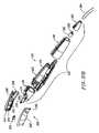
- FIG. 24is a perspective view of the distal portion of another electrosurgical probe according to the present invention.
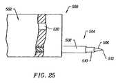
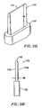
- FIG. 25illustrates another embodiment of the probe of the present invention, specifically designed for creating incisions in external skin surfaces
- FIG. 26is a perspective view of another embodiment of an electrosurgical probe for use in dermatology procedures.
- FIGS. 27A-27Care exploded, isometric views of the probe of FIG. 26 ;
- FIG. 29illustrates another embodiment of the electrosurgical probe of the present invention, incorporating additional active electrodes
- FIG. 30is a perspective view of an electrosurgical probe having a blade electrode
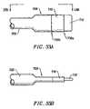
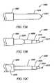
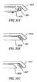
- FIGS. 33A and 33Bare a side view and a plan view, respectively, of the distal end of an electrosurgical probe having a terminal blade electrode, according to one embodiment of the invention.
- FIGS. 33C-33Eeach show a side view of the distal end of an electrosurgical probe having a terminal blade electrode, according to three different embodiments of the invention.
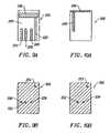
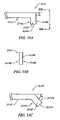
- FIGS. 34A , 34 B, and 34 Care a side view, a plan view, and an end view, respectively, of an electrosurgical probe having a terminal electrode support and a lateral blade electrode, according to another embodiment of the invention.
- FIGS. 35A , 35 B, and 35 Care a side view, a plan view, and an end view, respectively, of an electrosurgical probe having a lateral electrode support and a lateral blade electrode, according to another embodiment of the invention.
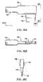
- FIGS. 36A and 36Beach show a side view of the distal end of an electrosurgical probe having a blade electrode, according to two different embodiments of the invention.
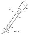
- FIGS. 37A and 37Bare a side view and an end view, respectively, of an electrosurgical probe having a lumen external to the probe shaft, according to one embodiment of the invention.
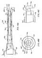
- FIGS. 39A , 39 B, and 39 Cschematically represent a perspective view, a longitudinal sectional view, and an end view, respectively, of an electrosurgical probe, according to another embodiment of the invention.
- FIGS. 40A and 40Bschematically represent a longitudinal sectional view, and an end view, respectively, of an electrosurgical probe, according to another embodiment of the invention.
- FIGS. 41A , 41 B, and 41 Ceach show detail of the distal portion of an electrosurgical probe, according to three different embodiments of the invention.
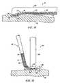
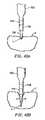
- FIGS. 42A and 42Bschematically represent a procedure for incising and coagulating tissue with an electrosurgical probe having a blade electrode, according to one embodiment of the invention
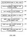
- FIG. 43Aschematically represents a number of steps involved in a method of treating a patient with an electrosurgical probe having a blade electrode, according to one embodiment of the invention
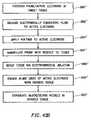
- FIG. 43Bschematically represents a number of steps involved in a method of concurrently severing and coagulating tissue, according to one embodiment of the invention.
- FIG. 44schematically represents a number of steps involved in a method of dissecting a tissue or organ of a patient with an electrosurgical probe, according to another embodiment of the invention.
- FIGS. 45A and 45Bare block diagrams, each schematically representing an electrosurgical system of the instant invention.
- FIGS. 47A and 47Bschematically represent an electrosurgical probe having a linearly movable return electrode, according to one embodiment of the invention
- FIGS. 49A and 49Bschematically represent an electrosurgical probe having a return electrode movable between electrical engagement and electrical disengagement, according to another embodiment of the invention.
- FIG. 50is a block diagram schematically representing an electrosurgical probe, according to another embodiment of the invention.
- FIGS. 51A and 51Bschematically represent an electrosurgical probe, having a linearly movable return electrode in a proximal location and a distal location, respectively;
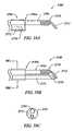
- FIGS. 54D and 54Eare longitudinal and transverse sectional views, respectively, of a movable return electrode/push rod assembly having a circular cross-section and a straight distal end;
- FIGS. 54F and 54Gare longitudinal and transverse sectional views, respectively, of a movable return electrode/push rod assembly having a semi-circular cross-section and an exposed, beveled distal end;
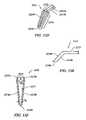
- FIGS. 55A and 55Bschematically represent a hook-like active electrode terminal, according to one embodiment of the invention.
- FIG. 55Cschematically represents a hook-like active electrode terminal, according to another embodiment of the invention.
- FIGS. 55D-Fschematically represent a hook-like active electrode, according to another embodiment of the invention.
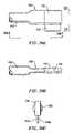
- FIG. 56Aschematically represents a multi-lumen tube for an electrosurgical probe, according to one aspect of the invention.
- FIG. 56Bschematically represents a multi-lumen tube, in perspective view, according to one embodiment the invention.
- FIG. 56Cis an end view of the multi-lumen tube of FIG. 56B showing a plurality of ports on an end plate of the tube in relation to a probe shaft;
- FIG. 56Dshows the location of an active electrode filament and a return electrode in relation to the plurality of ports of the multi-lumen tube of FIGS. 56B , 56 C;
- FIG. 57Ais a side view of a fixed return electrode in relation to the distal end of a multi-lumen tube, according to one embodiment of the invention.
- FIG. 57Cis an end view of the return electrode of FIG. 57B showing an electrically insulating spacer encircling an active electrode filament within the return electrode, according to one embodiment of the invention
- FIG. 58Ais an end view of the distal face of a multi-lumen tube indicating a location of an electrode assembly in relation to a fluid delivery port and an aspiration port, according to another aspect of the invention
- FIG. 58Bis a side view of the multi-lumen tube of FIG. 58A ;
- FIG. 59Ais a side view of an electrosurgical probe in the open configuration, with a movable return electrode retracted in a proximal location within the probe shaft, according to one embodiment of the invention
- FIG. 59Cis a sectional view taken along the lines 59 C- 59 C of FIG. 59B ;
- FIG. 60Aschematically represents a number of steps involved in a method of treating a target tissue of a patient with an electrosurgical probe, according to another embodiment of the invention.
- FIGS. 60B and 60Ceach schematically represents a number of steps involved in a method of severing a tissue of a patient, according to another embodiment of the invention.
- tissues which may be treated by the system and method of the present inventionfurther include, but are not limited to, tissues of the heart, chest, knee, shoulder, ankle, hip, elbow, hand or foot; as well as prostate tissue, leiomyomas (fibroids) located within the uterus, gingival tissues and mucosal tissues located in the mouth, tumors, scar tissue, myocardial tissue, collagenous tissue within the eye; together with epidermal and dermal tissues on the surface of the skin.
- the present inventionis also useful for resecting tissue within accessible sites of the body that are suitable for electrode loop resection, such as the resection of prostate tissue, leiomyomas (fibroids) located within the uterus, or other tissue to be removed from the body.
- tissuewithin accessible sites of the body that are suitable for electrode loop resection, such as the resection of prostate tissue, leiomyomas (fibroids) located within the uterus, or other tissue to be removed from the body.
- the present inventionis also useful for procedures in the head and neck, such as the ear, mouth, throat, pharynx, larynx, esophagus, nasal cavity, and sinuses. These procedures may be performed through the mouth or nose using speculae or gags, or using endoscopic techniques, such as functional endoscopic sinus surgery (FESS).
- FESSfunctional endoscopic sinus surgery
- These proceduresmay include the removal of swollen tissue, chronically-diseased inflamed and hypertrophic mucous linings, polyps and/or neoplasms from the various anatomical sinuses of the skull, the turbinates and nasal passages, in the tonsil, adenoid, epi-glottic and supra-glottic regions, and salivary glands, submucous resection of the nasal septum, excision of diseased tissue and the like.
- the present inventionmay be useful for cutting, resection, ablation and/or hemostasis of tissue in procedures for treating snoring and obstructive sleep apnea (e.g., UPPP procedures), for gross tissue removal, such as tonsillectomies, adenoidectomies, tracheal stenosis and vocal cord polyps and lesions, or for the resection or ablation of facial tumors or tumors within the mouth and pharynx, such as glossectomies, laryngectomies, acoustic neuroma procedures and nasal ablation procedures.
- the present inventionis useful for procedures within the ear, such as stapedotomies, tympanostomies, myringotomies, or the like.
- the present inventionis also useful for harvesting blood vessels, such as a blood vessel to be used as a graft vessel during the CABG procedure, e.g., the saphenous vein and the internal mammary artery (IMA).
- a blood vessel to be used as a graft vessel during the CABG proceduree.g., the saphenous vein and the internal mammary artery (IMA).
- One or more embodiments of the inventionmay be used as follows: i) to access the blood vessel to be harvested, e.g., by opening the leg to access the saphenous vein, or opening the chest (either via a longitudinal incision of the sternum during an open-chest procedure, or during a minimally invasive inter-costal procedure); ii) to dissect the blood vessel to be harvested from the surrounding connective tissue along at least a portion of its length; and iii) to transect the dissected blood vessel at a first position only in the case of a pedicled graft (IMA), or
- high frequency (RF) electrical energyis usually applied to one or more active electrodes in the presence of an electrically conductive fluid to remove and/or modify target tissue, an organ, or a body structure.
- the present inventionmay be used to: (1) create incisions in tissue; (2) dissect or harvest tissue; (3) volumetrically remove tissue or cartilage (i.e., ablate or effect molecular dissociation of the tissue); (4) cut, transect, or resect tissue or an organ (e.g., a blood vessel); (5) create perforations or holes within tissue; and/or (6) coagulate blood and severed blood vessels.
- an electrosurgical probeincludes an electrode support for electrically isolating the active electrode(s) from the return electrode, and a fluid delivery port or outlet for directing an electrically conductive fluid to the target site or to the distal end of the probe.
- the electrode support and the fluid outletmay be recessed from an outer surface of the instrument to confine the electrically conductive fluid to the region immediately surrounding the electrode support.
- a shaft of the instrumentmay be shaped so as to form a cavity around the electrode support and the fluid outlet. This helps to assure that the electrically conductive fluid will remain in contact with the active electrode(s) and the return electrode(s) to maintain the conductive path therebetween.
- the shaftwill usually have one or more wires, electrode connectors, leads, or other conductive elements running axially therethrough, to permit connection of the electrode(s) to a connection block located at the proximal end of the instrument.
- the connection blockis adapted for coupling the electrode(s) to the power supply or controller.
- the connection blockis housed within the handle of the probe.
- each individual active electrodeis electrically insulated from all other active electrodes within the probe and is connected to a power source which is isolated from each of the other active electrodes in the array, or to circuitry which limits or interrupts current flow to the active electrode when low resistivity material causes a low impedance path between the return electrode and the individual active electrode.
- the isolated power sources for each individual active electrodemay be separate power supply circuits having internal impedance characteristics which limit power to the associated active electrode when a low impedance return path is encountered.
- the isolated power sourcemay be a user selectable constant current source. In this embodiment, lower impedance paths will automatically result in lower resistive heating levels since the heating is proportional to the square of the operating current times the impedance.
- a single power sourcemay be connected to each of the active electrodes through independently actuatable switches, or by independent current limiting elements, such as inductors, capacitors, resistors and/or combinations thereof.
- the current limiting elementsmay be provided in the probe, connectors, cable, power supply or along the conductive path from the power supply to the distal tip of the probe.
- the resistance and/or capacitancemay occur on the surface of the active electrode(s) due to oxide layers which form selected active electrodes (e.g., titanium or a resistive coating on the surface of metal, such as platinum).
- the active electrodemay have a planar or blade shape, a screwdriver or conical shape, a sharpened point, a ball shape (e.g., for tissue vaporization and desiccation), a twizzle shape (for vaporization and needle-like cutting), a spring shape (for rapid tissue debulking and desiccation), a twisted metal shape, an annular or solid tube shape, or the like.
- the electrodemay comprise a plurality of filaments, a rigid or flexible brush electrode (for debulking a tumor, such as a fibroid, bladder tumor or a prostate adenoma), a side-effect brush electrode on a lateral surface of the shaft, a coiled electrode, or the like.
- the voltage difference applied between the return electrode(s) and the active electrode(s)will be at high or radio frequency, typically between about 5 kHz and 20 MHz, usually being between about 30 kHz and 2.5 MHz, preferably being between about 50 kHz and 500 kHz, often less than 350 kHz, and often between about 100 kHz and 200 kHz.
- the RMS (root mean square) voltage appliedwill usually be in the range from about 5 volts to 1000 volts, preferably being in the range from about 10 volts to 500 volts depending on the active electrode size, the operating frequency, and the operation mode of the particular procedure or desired effect on the tissue (e.g., contraction, coagulation, cutting or ablation).
- Electrosurgical system 11generally comprises an electrosurgical handpiece or probe 10 connected to a power supply 28 for providing high frequency voltage to a target site, and a fluid source 21 for supplying electrically conductive fluid 50 to probe 10 .
- electrosurgical system 11may include an endoscope (not shown) with a fiber optic head light for viewing the surgical site. The endoscope may be integral with probe 10 , or it may be part of a separate instrument.
- the system 11may also include a vacuum source (not shown) for coupling to a suction lumen or tube 211 (see FIG. 2 ) in the probe 10 for aspirating the target site.
- probe 10generally includes a proximal handle 19 and an elongate shaft 18 having one or more active electrodes 58 at its distal end.
- a connecting cable 34has a connector 26 for electrically coupling the active electrodes 58 to power supply 28 .
- active electrodes 58are electrically isolated from each other and the terminal of each active electrode 58 is connected to an active or passive control network within power supply 28 by means of a plurality of individually insulated conductors (not shown).
- a fluid supply tube 15is connected to a fluid tube 14 of probe 10 for supplying electrically conductive fluid 50 to the target site.
- Power supply 28has an operator controllable voltage level adjustment 30 to change the applied voltage level, which is observable at a voltage level display 32 .
- Power supply 28also includes first, second, and third foot pedals 37 , 38 , 39 and a cable 36 which is removably coupled to power supply 28 .
- the foot pedals 37 , 38 , 39allow the surgeon to remotely adjust the energy level applied to active electrode(s) 58 .
- first foot pedal 37is used to place the power supply into the “ablation” mode and second foot pedal 38 places power supply 28 into the “coagulation” mode.
- the third foot pedal 39allows the user to adjust the voltage level within the ablation mode.
- a sufficient voltageis applied to the active electrodes to establish the requisite conditions for molecular dissociation of the tissue (i.e., vaporizing a portion of the electrically conductive fluid, ionizing the vapor layer and accelerating charged particles against the tissue).
- the requisite voltage level for ablationwill vary depending on the number, size, shape and spacing of the electrodes, the distance in which the electrodes extend from the support member, etc.
- voltage level adjustment 30 or third foot pedal 39may be used to adjust the voltage level to adjust the degree or aggressiveness of the ablation.
- the power supply 28applies a low enough voltage to the active electrode(s) (or the coagulation electrode) to avoid vaporization of the electrically conductive fluid and subsequent molecular dissociation of the tissue.
- the surgeonmay automatically switch the power supply between the ablation and coagulation modes by alternately stepping on foot pedals 37 , 38 , respectively. This allows the surgeon to quickly move between coagulation and ablation in situ, without having to remove his/her concentration from the surgical field or without having to request an assistant to switch the power supply.
- the probetypically will simultaneously seal and/or coagulation small severed vessels within the tissue.
- Handle 204typically comprises a plastic material that is easily molded into a suitable shape for handling by the surgeon. Handle 204 defines an inner cavity (not shown) that houses an electrical connections unit 250 ( FIG. 5 ), and provides a suitable interface for coupling probe 20 to power supply 28 via an electrical connecting cable. Electrode support member 102 extends from the distal end of shaft 100 (usually about 1 mm to 20 mm), and provides support for an active electrode or a plurality of electrically isolated active electrodes 104 . In the specific configuration shown in FIG. 2 , probe 20 includes a plurality of active electrodes. As shown in FIG.
- a fluid tube 233extends through an opening in handle 204 , and includes a connector 235 for connection to a fluid supply source for supplying electrically conductive fluid to the target site.
- Fluid tube 233is coupled to a distal fluid tube 239 that extends along the outer surface of shaft 100 to an opening 237 at the distal end of the probe 20 , as will be discussed in detail below.
- fluid tube 233may extend through a single lumen (not shown) in shaft 100 , it may be coupled to a plurality of lumina (also not shown) that extend through shaft 100 to a plurality of openings at its distal end, or the fluid tube may be completely independent of shaft 100 .
- Probe 20may also include a valve or equivalent structure for controlling the flow rate of the electrically conductive fluid to the target site.
- electrode support member 102has a substantially planar tissue treatment surface 212 and comprises a suitable insulating material (e.g., a ceramic or glass material, such as alumina, zirconia, and the like) which could be formed at the time of manufacture in a flat, hemispherical or other shape according to the requirements of a particular procedure.
- a suitable insulating materiale.g., a ceramic or glass material, such as alumina, zirconia, and the like
- the preferred support member materialis alumina (Kyocera Industrial Ceramics Corporation, Elkgrove, Ill.), because of its high thermal conductivity, good electrically insulative properties, high flexural modulus, resistance to carbon tracking, biocompatibility, and high melting point.
- active electrodes 104extend through pre-formed openings in the support member 102 so that they protrude above tissue treatment surface 212 by the desired distance. The electrodes are then bonded to the tissue treatment surface 212 of support member 102 , typically by an inorganic sealing material.
- the sealing materialis selected to provide effective electrical insulation, and good adhesion to both support member 102 and active electrodes 104 .
- active electrodes 104comprise an electrically conducting, corrosion resistant metal, such as platinum or titanium.
- the sealing materialadditionally should have a compatible thermal expansion coefficient and a melting point well below that of platinum or titanium and alumina or zirconia, typically being a glass or glass ceramic.
- probe 20includes a return electrode 112 for completing the current path between active electrodes 104 and a high frequency power supply 28 (see FIG. 1 ).
- return electrode 112preferably comprises an annular conductive band coupled to the distal end of shaft 100 at a location proximal to tissue treatment surface 212 of electrode support member 102 , typically about 0.5 mm to 10 mm proximal to surface 212 , and more preferably about 1 mm to 10 mm proximal to surface 212 .
- Return electrode 112is coupled to a connector 258 that extends to the proximal end of probe 20 , where it is suitably connected to power supply 28 ( FIGS. 1 and 2 ).
- return electrode 112is not directly connected to active electrodes 104 .
- electrically conductive fluide.g., isotonic saline
- the electrically conductive fluidis delivered through an external fluid tube 239 to opening 237 , as described above ( FIGS. 2 and 4 ).
- the fluidmay be continuously delivered by a fluid delivery element (not shown) that is separate from probe 20 .
- the fluid pathmay be formed in probe 20 by, for example, an inner lumen or an annular gap between the return electrode and a tubular support member within shaft 100 (not shown).
- This annular gapmay be formed near the perimeter of the shaft 100 such that the electrically conductive fluid tends to flow radially inward towards the target site, or it may be formed towards the center of shaft 100 so that the fluid flows radially outward.
- a fluid sourcee.g., a bag of fluid elevated above the surgical site or having a pumping device
- a fluid supply tube(not shown) that may or may not have a controllable valve.
- the electrically isolated active electrodes 104are preferably spaced from each other and aligned to form a linear array 105 of electrodes for cutting a substantially linear incision in the tissue.
- the tissue treatment surface and individual active electrodes 104will usually have dimensions within the ranges set forth above.
- Active electrodes 104preferably have a distal edge 107 to increase the electric field intensities around terminals 104 , and to facilitate cutting of tissue.
- active electrodes 104have a screwdriver shape in the representative embodiment of FIGS. 2-4 .
- the tissue treatment surface 212has a circular cross-sectional shape with a diameter in the range of about 1 mm to 30 mm, usually about 2 mm to 20 mm.
- the individual active electrodes 104preferably extend outward from tissue treatment surface 212 by a distance of about 0.1 mm to 8 mm, usually about 1 mm to 4 mm. Applicant has found that this configuration increases the high electric field intensities and associated current densities around active electrodes 104 to facilitate the ablation of tissue as described in detail above.
- Probe 20may include a suction or aspiration lumen 213 (see FIG. 2 ) within shaft 100 and a suction tube 211 ( FIG. 2 ) for aspirating tissue, fluids and/or gases from the target site.
- the electrically conductive fluidgenerally flows from opening 237 of fluid tube 239 radially inward and then back through one or more openings (not shown) in support member 102 .
- Aspirating the electrically conductive fluid during surgeryallows the surgeon to see the target site, and it prevents the fluid from flowing into the patient's body (e.g., the thoracic cavity). This aspiration should be controlled, however, so that the conductive fluid maintains a conductive path between the active electrode(s) and the return electrode.
- the probe 20will also include one or more aspiration electrode(s) (not shown) coupled to the aspiration lumen for inhibiting clogging during aspiration of tissue fragments from the surgical site.
- aspiration electrode(s)not shown
- FIG. 5illustrates the electrical connections 250 within handle 204 for coupling active electrodes 104 and return electrode 112 to the power supply 28 .
- a plurality of wires 252extend through shaft 100 to couple electrodes 104 to a plurality of pins 254 , which are plugged into a connector block 256 for coupling to a connecting cable 22 ( FIG. 1 ).
- return electrode 112is coupled to connector block 256 via a wire 258 and a plug 260 .
- the voltage reduction elementprimarily allows the electrosurgical probe 10 / 20 to be compatible with a range of different power supplies that are adapted to apply higher voltages for ablation or vaporization of tissue (e.g., various power supplies or generators manufactured by ArthroCare Corporation, Sunnyvale, Calif.).
- the voltage reduction elementwill serve to reduce a voltage of about 100 to 135 volts RMS (which corresponds to a setting of 1 on the ArthroCare Model 970 and 980 (i.e., 2000) Generators) to about 45 to 60 volts RMS, which is a suitable voltage for contraction of tissue without ablation (e.g., molecular dissociation) of the tissue.
- the voltage reduction elementis a dropping capacitor 262 which has a first leg 264 coupled to the return electrode wire 258 and a second leg 266 coupled to connector block 256 .
- the capacitormay be located in other places within the system, such as in, or distributed along the length of, the cable, the power supply, the connector, etc.
- other voltage reduction elementssuch as diodes, transistors, inductors, resistors, capacitors or combinations thereof, may be used in conjunction with the present invention.
- probe 20may include a coded resistor (not shown) that is constructed to lower the voltage applied between return electrode 112 and active electrodes 104 to a suitable level for contraction of tissue.
- electrical circuitsmay be employed for this purpose.
- the cable 22 that couples the power supply 28 to probe 10 / 20may be used as a voltage reduction element.
- the cablehas an inherent capacitance that can be used to reduce the power supply voltage if the cable is placed into the electrical circuit between the power supply, the active electrodes and the return electrode.
- the cable 22may be used alone, or in combination with one of the voltage reduction elements discussed above, e.g., a capacitor.
- electrosurgical probes of the present inventioncan be used with a particular power supply that is adapted to apply a voltage within a selected range for a certain procedure or treatment. In which case, a voltage reduction element or circuitry may not be necessary nor desired.
- First ceramic layer 200further includes a gold conductive strip 222 extending from return electrode 216 to the proximal end of layer 200 for coupling to a lead wire (not shown), and three gold conductive lines 224 , 226 , 228 extending from a mid-portion of layer 200 to its proximal end.
- Conductive strips 224 , 226 , 228are each coupled to one of the active electrodes 210 a , 210 b , 210 c by conductive holes or vias 230 , 232 , 234 , respectively. As shown, all three vias 230 , 232 , 234 extend through wafer layer 200 .
- a second outer wafer layer 208has a second return electrode 218 plated to the lateral surface 250 of layer 208 .
- the second return electrode 218is coupled directly to the first return electrode 216 through a via 252 extending through the entire ceramic substrate.
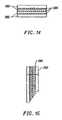
- FIGS. 14 and 15illustrate an alternative embodiment of the multi-layer ceramic wafer, wherein the active electrodes comprise planar strips 280 that are plated or otherwise bonded between the ceramic wafer layers 282 .
- the active electrodescomprise planar strips 280 that are plated or otherwise bonded between the ceramic wafer layers 282 .
- Each of the planar strips 280has a different length, as shown in FIG. 15 , so that the active electrodes can be electrically isolated from each other, and coupled to lead wires by vias (not shown).
- FIGS. 17A-17Cschematically illustrate the distal portion of three different embodiments of a probe 90 according to the present invention.
- active electrodes 104are anchored in a support 102 of suitable insulating material (e.g., ceramic or glass material, such as alumina, zirconia and the like) which could be formed at the time of manufacture in a flat, hemispherical or other shape according to the requirements of a particular procedure.
- the support materialis alumina, available from Kyocera Industrial Ceramics Corporation, Elkgrove, Ill., because of its high thermal conductivity, good electrically insulative properties, high flexural modulus, resistance to carbon tracking, biocompatibility, and high melting point.
- FIG. 25illustrates a distal portion of an electrosurgical probe 500 according to another embodiment of the present invention.
- Probe 500comprises a support member 502 coupled to a shaft or disposable tip (not shown) as described in previous embodiments.
- Support member 502preferably comprises an inorganic electrically insulating material, such as ceramic, glass, or glass-ceramic.
- support member 502may comprise an organic material, such as plastic, because the active electrode 506 and return electrode 508 are both spaced away from support member 502 .
- the high intensity electric fieldsmay be far enough away from support member 502 so as to allow an organic material.
- tip 313further includes a proximal hub 506 for supporting a male electrical connector 508 that holds a plurality of wires 510 each coupled to one of the active electrodes 358 or to return electrode 400 on support member 370 .
- a female connector 520 housed within handle 312is removably coupled to male connector 508 , and a plurality of wires 522 extend from female connector 520 through a strain relief 524 to cable 334 . Both sets of wires 510 , 522 are insulated to prevent shorting in the event of fluid ingress into the probe 310 .
- Electrode array 436is preferably flush with the distal end of shaft 432 or distally extended from the distal end by a small distance (on the order of 0.005 inches) so as to minimize the depth of ablation.
- the distal end of shaft 432is beveled to improve access and control of probe 430 while treating the target tissue.
- the voltagewill preferably be sufficient to establish high electric field intensities between the active electrode array 436 and the target tissue 440 to thereby induce molecular breakdown or disintegration of several cell layers of the target tissue.
- a sufficient voltagewill be applied to develop a thin layer of vapor within the electrically conductive fluid and to ionize the vaporized layer or region between the active electrode(s) and the target tissue. Energy in the form of charged particles are discharged from the vapor layer to ablate the target tissue, thereby minimizing necrosis of surrounding tissue and underlying cell layers.
- Active electrode 712comprises a blade electrode (e.g., FIGS. 31A , 31 B).
- An electrically insulating sleeve 716covers a portion of shaft 702 , and terminates at sleeve distal end 716 a to define an exposed portion of shaft 702 extending between electrode support proximal end 710 b and sleeve distal end 716 a .
- This exposed portion of shaft 702defines a return electrode 718 on shaft distal end portion 702 a .
- FIG. 35Ashows in side view an electrosurgical probe 700 having electrode support 710 mounted laterally on the distal end of shaft 702 , according to another embodiment of the invention.
- Blade active electrode 712is mounted laterally on electrode support 710 .
- FIG. 35Bis a plan view of probe 700 taken along the lines 35 B- 35 B of FIG. 35A .
- FIG. 35Cis an end view taken along the lines 35 C- 35 C of FIG. 35A .
- Active electrode 712is in the form a substantially flat, metal blade having first and second blade sides 714 a , 714 b , substantially parallel to each other.
- Electrode support 710is mounted laterally on laterally compressed region 703 of shaft 702 .
- Lumen 726 ′typically serves as a conduit for delivery of an electrically conductive fluid to the shaft distal end.
- FIG. 38Bis an end view of probe 700 taken along the lines 38 B- 38 B of FIG. 38A , showing outer sheath 722 and lumen 726 ′ in relation to shaft 702 .
- the diameter of outer sheath 722is, at least to some extent, a matter of design choice.
- Outer sheath 722may comprise a substantially rigid or somewhat flexible plastic tube comprising polyethylene, a polyimide, and the like.
- FIG. 39Aschematically represents an electrosurgical probe 700 , according to another embodiment of the invention.
- Probe 700includes shaft 702 and handle 704 affixed at shaft proximal end 702 b .
- a first electrode support 711 a and a second electrode support 711 bare disposed at shaft proximal end 702 a .
- a blade active electrode 712is arranged on first and second electrode supports, 711 a , 711 b .
- Each of first and second electrode supports 711 a , 711 bmay comprise a refractory and electrically insulating material, such as a silicone rubber or the like, as described hereinabove.
- a return electrode 718is located at shaft distal end 702 proximal to first and second electrode supports 711 a , 711 b .
- Return electrode 718may comprise an exposed portion of shaft distal end 702 a (e.g., FIGS. 32A-C ).
- Blade active electrode 712typically extends distally from electrode support 710 by a distance in the range of from about 0.1 mm to about 10 mm, an more typically from about 2 mm to 10 mm.
- Blade active electrode 712 and return electrode 718may be independently coupled to opposite poles of a high frequency power supply via electrode leads (not shown) and a connection block (e.g., FIG. 30 ).
- an active electrode leadis coupled to one of first and second electrode arms 715 a , 715 b , and the other arm terminates in a free, electrically isolated end, for example, within first electrode support 711 a or second electrode support 711 b .
- Blade active electrode 712includes a crosspiece 715 c ( FIGS. 39B-D ) located distal to aspiration port 734 .
- a fluid delivery element or unit including an outer sheath 722 ′is omitted from FIG. 39A for the sake of clarity.
- FIG. 39Bis a partial sectional view of probe 700 of FIG. 39A as seen from the side.
- Outer sheath 722 ′defines an annular fluid delivery lumen 726 ′ between sheath 722 ′ and shaft 702 .
- Lumen 726 ′terminates in an annular fluid delivery port 725 at shaft distal end 702 a .
- Fluid delivery lumen 726 ′is in communication proximally with a fluid delivery tube 721 .
- Solid arrowsindicate the direction of flow of an electrically conductive fluid (e.g., isotonic saline) within fluid delivery lumen 726 ′.
- Aspiration port 734is in communication proximally with an aspiration lumen 732 and an aspiration tube 730 .
- FIG. 39Cis an end view of probe 700 taken along the lines 39 C- 39 C of FIG. 39B .
- Active electrode 712includes crosspiece 715 c extending between first and second electrode arms 715 a , 715 b , respectively ( FIG. 39D ).
- Active electrode 712further includes first and second blade sides 714 a , 714 b .
- first and second blade sides 714 a , 714 bare adapted for engaging tissue that has been severed, and for coagulating the severed tissue.
- Crosspiece 715 cat least partially spans aspiration port 734 .
- active electrode 712comprises a single metal blade, comprising a material such as platinum, tungsten, palladium, iridium, or titanium, or their alloys.
- FIG. 39Dshows detail of the distal portion of probe 700 of FIGS. 39A-C including blade active electrode 712 .
- first and second electrode arms 715 a , 715 bare disposed on first and second electrode supports 711 a , 711 b , respectively.
- first and second electrode arms 715 a , 715 bmay be disposed on a single annular electrode support having a substantially central void defining aspiration port 734 .
- active electrode 712includes both a distal active edge 713 a , and a proximal active edge 713 b .
- Distal active edge 713 ais adapted for aggressively ablating tissue via molecular dissociation of tissue components and for severing tissue targeted for resection, transection, dissection, or other treatment.
- FIG. 40Ais a partial sectional view of an electrosurgical probe 700 according to another embodiment of the invention.
- Probe 700 of FIG. 40Agenerally includes shaft 702 and handle 704 , together with a fluid delivery element, and an aspiration unit, essentially as for the embodiment described with reference to FIGS. 39A-D .
- the embodiment of FIG. 40Adiffers from other embodiments described herein in having an active electrode in the form of a plasma hook 712 ′.
- Hook 712 ′is in some respects analogous to plasma blade electrodes described hereinabove.
- Hook 712 ′includes a first axial portion 712 ′ a ( FIG. 40C ) in contact at its proximal end with electrode support 710 .
- Hook 712 ′may further include a second portion 712 ′ b extending from the distal portion of first axial portion 712 ′ a .
- second portion 712 ′ bis arranged substantially orthogonal to first axial portion 712 ′ a .
- second portion 712 ′ bmay be structurally similar or analogous to crosspiece 715 c of the embodiment of FIGS. 39A-D .
- Electrode support 710may comprise a refractory and electrically insulating material, such as a silicone rubber or the like, as described hereinabove.
- hook 712 ′is curved, having a concave distal edge 713 a , and a convex proximal edge 713 b .
- second portion 712 ′ bmay have a length which is less than, equal to, or greater than the diameter of shaft 702 . In the latter case, second portion 712 ′ b extends laterally beyond the exterior surface of shaft 702 (e.g., FIG. 41C ).
- hook 712 ′typically comprises a single blade having first and second blade sides 714 a , 714 b (e.g., FIG. 40B ).
- Hook 712 ′typically comprises a metal such as platinum, tungsten, palladium, iridium, or titanium, or their alloys.
- FIGS. 42A-Bschematically represent a process during treatment of a patient with electrosurgical probe 700 .
- Blade active electrode 712is affixed to support 710 on shaft 702 .
- Blade active electrode 712includes active edge 713 and first and second blade sides, 714 a , 714 b (e.g., FIGS. 31A-B ).
- active edge 713forms an incision, I, in a target tissue, T, via localized molecular dissociation of tissue components upon application of a high frequency voltage between active electrode 712 and return electrode 718 .
- the localized molecular dissociationmay be facilitated by the delivery of a suitable quantity of an electrically conductive fluid (e.g.
- first and second blade sides, 714 a , 714 bengage severed tissue in regions indicated by the arrows labeled E. In this way, the severed tissue is coagulated by first and second blade sides, 714 a , 714 b , thereby effecting hemostasis at the point of incision of the tissue.
- the root mean square (RMS) voltage that is applied in step 1004is generally in the range of from about 5 volts to 1000 volts RMS, more typically being in the range of from about 10 volts to 500 volts RMS.
- the actual voltage appliedmay depend on a number of factors, including the size of the active electrode, the operating frequency, and the particular procedure or desired type of modification of the tissue (incision, contraction, etc.), as described hereinabove.
- Step 1008involves modifying the target tissue as a result of the high frequency voltage applied in step 1004 .
- the target tissuemay be modified in a variety of different ways, as referred to hereinabove.
- the type of tissue modification achieveddepends, inter alia, on the voltage parameters of step 1004 ; the shape, size, and composition of the active electrode; and the manner in which the probe is manipulated by the surgeon in step 1006 .
- tissue componentstypically undergo localized molecular dissociation, whereby the target tissue can be dissected, incised, transected, etc.
- the target tissuecan be contracted (e.g., by shrinkage of collagen fibers in the tissue), or a blood vessel can be coagulated.
- the first and second blade sides of the active electrodemay be engaged against a region of the target tissue which has been modified as a result of localized molecular dissociation of tissue components in step 1008 .
- the first and second blade sidesare substantially flat metal plates having lower current densities than the active edge. In this manner, the lower current densities of the first and second blade sides cause further modification (e.g., coagulation) of the previously modified (e.g., severed) target tissue (step 1012 ).
- FIG. 43Bschematically represents a number of steps involved in a method of severing tissue with an electrosurgical probe via a process involving molecular dissociation of tissue components, and of coagulating the severed tissue with the same electrosurgical probe during a single procedure, according to one embodiment of the invention.
- the electrosurgical probetypically comprises an active electrode in the form of a single, substantially flat metal hook or blade having at least one active edge adapted for electrosurgically severing the tissue, and first and second blade sides adapted for effecting hemostasis of the severed tissue.
- Steps 1000 ′ through 1006 ′are substantially the same or analogous to steps 1000 through 1006 , as described hereinabove with reference to FIG. 43A .
- FIG. 44schematically represents a number of steps involved in a method of dissecting a tissue or organ of a patient with an electrosurgical probe having a hook or blade active electrode, according to one embodiment of the invention, wherein step 1100 involves accessing an organ or tissue.
- accessing an organ or tissue in step 1100involves incising an overlying tissue which conceals the organ or tissue to be dissected.
- the thoracic cavityis accessed by making a longitudinal incision though the sternum.
- Incising an overlying tissue in step 1100may be performed generally according to the methods described with reference to FIG. 43A or 43 B.
- Step 1102involves positioning the distal end of the electrosurgical probe, and in particular an active edge of the hook or blade active electrode, in at least close proximity to connective tissue adjacent to the tissue or organ to be dissected.
- the connective tissuemay be soft tissue, such as adipose tissue, or relatively hard tissue such as cartilage or bone.
- Optional step 1104involves delivering an electrically conductive fluid to the distal end of the probe such that the electrically conductive fluid forms a current flow path between the active electrode and the return electrode, generally as described for step 1002 , supra.
- Step 1106involves applying a high frequency voltage between the active electrode and the return electrode, generally as described for step 1004 , supra.
- High frequency power supply 1250may be readily switched between the ablation mode and the sub-ablation mode by the surgeon during operation of system 1200 , for example, using one or more foot pedals (e.g., FIG. 1 ).
- first return electrode 1218is fixed in relation to active electrode 1212 .
- second return electrode 1270is typically movable with respect to active electrode 1212 (e.g., FIGS. 47A-B , 59 A-B).
- FIG. 46is a block diagram schematically representing an electrosurgical probe 1300 , according to the invention.
- Probe 1300includes a fixed electrode assembly 1320 and a handle 1304 housing a connection block 1306 .
- Assembly 1320includes an active electrode 1312 and a fixed return electrode 1318 , both coupled to connection block 1306 .
- Probe 1300further includes a movable return electrode 1370 also coupled to connection block 1306 .
- Connection block 1306provides a convenient mechanism for coupling each of active electrode 1310 , fixed return electrode 1318 , and movable return electrode 1370 to a high frequency power supply (e.g., FIGS. 1 , 45 A).
- Probe 1300further includes an actuator unit 1390 , in communication with movable return electrode 1370 , for moving movable return electrode 1370 .
- actuator unit 1390in communication with movable return electrode 1370 , for moving movable return electrode 1370 .
- movable return electrode 1370is movable linearly with respect to active electrode 1312 (e.g., FIGS. 47A-49B ).
- active electrode terminal 1412is in the form of a hook.
- the active electrode terminalcomprises a flattened wire and a proximal end of the wire is coupled directly to the connection block.
- Other configurations for the active electrode terminalare also within the scope of the invention.
- probe 1400further includes a movable return electrode 1470 .
- movable return electrode 1470is coupled to connection block 1406 via a push rod 1471 and a second return lead 1476 .
- a proximal portion of push rod 1471is ensheathed within an electrically insulating sleeve, and an exposed (non-insulated), distal portion of rod 1471 defines return electrode 1470 .
- Movable return electrode 1470is movable linearly with respect to active electrode terminal 1412 in a direction substantially parallel to the longitudinal axis of shaft 1402 . Movable return electrode 1470 may be moved between (i) a distal location ( FIG.
- movable return electrode 1470in which movable return electrode 1470 is adjacent to active electrode terminal 1412 , and (ii) a proximal location ( FIG. 47B ), in which movable return electrode 1470 is retracted, e.g., within shaft 1402 .
- movable return electrode 1470defines a primary current path from active electrode terminal 1412 to the power supply (e.g., FIGS. 1 , 45 A, 45 B).
- movable return electrode 1470In the retracted (proximal) location, movable return electrode 1470 is mechanically disengaged, or physically separated, from active electrode terminal 1412 , and no longer provides a substantial current path from active electrode terminal 1412 to the power supply.
- the distal location of movable return electrode 1470FIG.
- FIG. 47Arepresents a closed configuration of probe 1400
- the proximal location of movable return electrode 1470( FIG. 47B ) represents an open configuration of probe 1400 .
- fixed return electrode 1418provides the primary current path from active electrode terminal 1412 to the power supply.
- the distal end of movable return electrode 1470may be beveled at an angle, e.g., of about 45°, and active electrode terminal 1412 may be configured at a corresponding or complementary angle.
- moveable return electrode 1470may be moved between the distal location and the proximal location via an actuator unit 1490 .
- actuator unit 1490is located on handle 1404 .
- actuator unit 1490may alternatively be located at other locations, e.g., on shaft proximal end 1402 b .
- Moveable return electrode 1470may be moved distally towards the closed configuration to capture, clamp, and weld or coagulate a blood vessel (e.g., FIGS. 53A-C ) during a broad range of surgical procedures.
- active electrode terminal 1412is adapted for cutting, dissecting, and severing a tissue or organ.
- a gapexists between the distal end of movable return electrode 1470 and a proximal face of active electrode terminal 1412 .
- the gap in the closed configurationis typically in the range of from about 0.2 mm to 2 mm.
- movable return electrode 1470is retracted and separated from active electrode terminal 1412 by a greater distance, typically in the range of from about 5 mm to 3 cm.
- FIGS. 48A and 48Bschematically represent an electrosurgical probe 1500 , according to another embodiment of the invention.
- Probe 1500includes a number of elements which are the same as, or analogous to, those described for probe 1400 with reference to FIGS. 47 A-B.
- probe 1500includes a shaft 1502 having a shaft distal end 1502 a , and a shaft proximal end 1502 b ; a handle 1504 affixed to shaft proximal end 1502 b ; a connection block 1506 ; a fixed return electrode 1518 disposed at shaft distal end 1402 a ; an electrically insulating spacer 1510 extending to a location distal to fixed return electrode 1518 ; and an active electrode terminal 1512 disposed distal to spacer 1510 .
- Active electrode terminal 1512 and fixed return electrode 1518are independently coupled to connection block 1506 via electrode leads (not shown).
- probe 1500is electrically coupled to a high frequency power supply (e.g., FIG. 1 ) via connection block 15
- probe 1500also includes a movable return electrode 1570 .
- movable return electrode 1570is movable linearly in a direction substantially parallel to the longitudinal axis of shaft 1502 , between a distal location ( FIG. 48A ) and a proximal location ( FIG. 48B ).
- a proximal portion of movable return electrode 1570comprises a movable rod or push rod 1571 .
- rod 1571lies external to shaft 1502 .
- rod 1571comprises an electrically insulated portion 1574 , and an electrically conducting zone 1572 proximal to insulated portion 1574 .
- Probe 1500further includes a contact unit 1580 coupled to connection block 1506 via a second return lead 1576 .
- Contact unit 1580may be in the form of a cylinder of electrically conducting material which makes electrical contact with movable return electrode 1570 when electrically conducting zone 1572 lies within contact unit 1580 ( FIG. 48A ).
- movable return electrode 1570is electrically coupled to connection block 1506 .
- electrically conducting zone 1572is moved proximal of contact unit 1580 ( FIG. 48B )
- movable return electrode 1570is electrically uncoupled from connection block 1506 .
- Moveable return electrode 1570may be moved between the distal location and the proximal location via an actuator unit (not shown in FIGS. 48A-B ).
- movable return electrode 1570defines a primary current path from active electrode terminal 1512 to the power supply.
- movable return electrode 1570In the retracted position (proximal location or open configuration), movable return electrode 1570 is electrically disengaged from connection block 1506 , and no longer provides a current path from active electrode terminal 1512 to the power supply.
- fixed return electrode 1518provides a current path from active electrode terminal 1512 to the power supply.
- active electrode terminal 1512is adapted for cutting, dissecting, and severing a tissue or organ.
- probe 1500is adapted for the capture, clamping, and welding or coagulation of a blood vessel during various surgical procedures (e.g., FIGS. 53A-C ).
- FIGS. 49A and 49Bschematically represent an electrosurgical probe having a return electrode movable between electrical engagement and electrical disengagement, according to another embodiment of the invention.
- Probe 1600is somewhat analogous, both structurally and functionally, to probe 1500 described hereinabove with reference to FIGS. 48A-B .
- probe 1600includes a shaft 1602 having a shaft distal end 1602 a , and a shaft proximal end 1602 b ; a handle 1604 affixed to shaft proximal end 1602 b ; a connection block 1606 ; a fixed return electrode 1618 disposed at shaft distal end 1602 a ; an electrically insulating spacer 1610 extending to a location distal to fixed return 1618 ; and an active electrode terminal 1612 extending distal to spacer 1610 .
- Probe 1600also includes a movable return electrode 1670 movable linearly in a direction substantially parallel to the longitudinal axis of shaft 1602 between an electrically coupled distal location ( FIG.
- probe 1600is coupled to a high frequency power supply (e.g., FIGS. 1 , 45 A-B) via connection block 1606 .
- the mechanism shown for electrically coupling and uncoupling movable return electrode 1670is analogous to that of the embodiment described with reference to FIGS. 48A-B .
- a movable push rod 1671comprises an electrically insulated portion 1674 , and a proximal electrically conducting zone 1672 .
- Contact unit 1680is coupled to connection block 1606 via a second return lead 1676 .
- Moveable return electrode 1618is electrically coupled to connection block 1606 when electrically conducting zone 1672 lies within contact unit 1680 ( FIG. 49A ), i.e., when probe 1600 is in the closed configuration.
- movable return electrode 1670is electrically uncoupled from connection block 1606 .
- push rod 1671lies internal to shaft 1602 .
- Moveable return electrode 1670may be moved between the distal location and the proximal location via an actuator unit (not shown in FIGS. 49A-B ).
- the actuator unitmay take the form of a slidable attachment (not shown) located on handle 1604 .
- Probe 1300 ′further includes a fixed return electrode 1318 ′, and an active electrode terminal 1312 ′ disposed on a second spacer 1310 .
- second spacer 1310extends distally from an internal lumen of first spacer 1308 .
- Probe 1300 ′still further includes a movable return electrode 1370 ′, and an actuator unit 1390 for moving movable return electrode 1370 ′ with respect to active electrode terminal 1312 ′, between a distal location and a proximal location.
- movable return electrode 1370 ′is movable in a direction parallel to the longitudinal axis of shaft 1302 , as described hereinabove (e.g., with reference to FIGS. 47A-B ).
- probe 1300 ′is configured such that movable return electrode 1370 ′ slides external to tube 1303 and within (internal to) shaft 1302 (e.g., FIGS. 52A-C ).
- FIG. 51Aschematically represents an electro surgical probe 1700 having a linearly movable return electrode 1770 , wherein movable return electrode 1770 is shown in a proximal location.
- the proximal location of movable return electrode 1770defines an open configuration of probe 1700 .
- FIG. 51Bschematically represents the distal or working end of probe 1700 showing movable return electrode 1770 in a distal location (closed configuration).
- Probe 1700includes a shaft 1702 having a shaft distal end 1702 a and a shaft proximal end 1702 b , and a handle 1704 affixed to shaft proximal end 1702 b .
- An electrically insulating multi-lumen tube 1703lies within, and extends distally from, shaft 1702 .
- a distal portion of tube 1703 protruding from shaft distal end 1702 adefines a first electrically insulating spacer 1708 .
- a fixed return electrode 1718is disposed on first spacer 1708 .
- Tube 1703serves as a spacer to separate, or space, fixed return electrode 1718 from movable return electrode 1770 .
- First electrically insulating spacer 1708may extend from shaft distal end 1702 a by a distance in the range of from about 0.3 to 2.5 inches, and more typically from about 0.5 to 2.0 inches.
- fixed return electrode 1718is in the form of a coil.
- return electrode 1718may be a coil of wire having from about three (3) to ten (10) turns (e.g., FIGS. 57A-C ).
- a second electrically insulating spacer 1710lies within the coil of return electrode 1718 .
- An active electrode terminal 1712extends distally from second spacer 1710 at an angle of about 45°.
- Other shapes and configurations for the fixed return electrode and the active electrodeare also within the scope of the invention.
- movable return electrode 1770may be mechanically disengaged, i.e., rendered non-functional as a return electrode, by being retracted within shaft 1702 . Additionally, or alternatively, movable return electrode 1770 may alternate between electrical coupling and electrical uncoupling by translation of movable return electrode 1770 between the distal location of FIG. 51B , and the proximal location of FIG. 51A , respectively. As an example, movable return electrode 1770 may be electrically coupled and uncoupled to a connection block via a mechanism analogous to that described with reference to FIGS. 49A-B .
- FIG. 51Cis a sectional view taken along the lines 51 C- 51 C of FIG.
- FIG. 51Ashowing movable return electrode 1770 disposed internal to shaft 1702 and external to multi-lumen tube 1703 . Internal lumina of tube 1703 are omitted from FIG. 51C for the sake of clarity. As shown in FIG. 51C , movable return electrode 1770 is semicircular in cross-section, however other configurations for the movable return electrode are also within the scope of the invention (e.g., FIGS. 54A-C ).
- FIGS. 52A-Cshow the distal or working end of an electrosurgical probe 1800 , as seen from an inferior location.
- FIG. 52Ashows probe 1800 in a closed configuration, with a movable return electrode 1870 extending distally from shaft 1802 to a distal location such that movable return electrode 1870 lies adjacent to an active electrode terminal 1812 .
- movable return electrode 1870defines the primary current path from active electrode terminal 1812 .
- Active electrode terminal 1812is partially obscured by return electrode 1870 in FIG. 52A .
- Moveable return electrode 1870may have a circular or semi-circular cross-sectional shape and a beveled or straight distal end.
- Moveable return electrode 1870may comprise a metal such as stainless steel, platinum, molybdenum, tungsten, palladium, iridium, titanium, or their alloys.
- FIG. 52Bshows probe 1800 having movable return electrode 1870 partially retracted to reveal a portion of a first electrically insulating spacer 1808 , a fixed return electrode 1818 disposed distal to first spacer 1808 , and a second electrically insulating spacer 1810 extending distal to fixed return electrode 1818 .
- First spacer 1808serves to separate, isolate, or space fixed return electrode 1818 from movable return electrode 1870 .
- FIG. 52Cshows probe 1800 in an open configuration, with movable return electrode 1870 retracted within shaft 1802 . In the open configuration, fixed return electrode 1818 defines the primary current path from active electrode terminal 1812 .
- FIGS. 53A-Cschematically represent an active electrode terminal 1912 and a linearly movable return electrode 1970 of an electrosurgical probe of the invention, in relation to a blood vessel, BV.
- blood vessel, BVmay be a vessel encountered by a surgeon during cutting or resection of tissue, wherein cessation of blood flow within the vessel may be required prior to severing the vessel.
- Linear movement of movable return electrode 1970 toward active electrode terminal 1912is indicated by the solid arrow.
- Moveable return electrode 1970may be moved in the indicated direction by actuation of an actuator unit (e.g., FIGS. 46 , 47 A-B).
- FIG. 53Bshows the probe in the closed configuration, with blood vessel, BV′ compressed between active electrode terminal 1912 and movable return electrode 1970 .
- movable return electrode 1970may be continuously urged in the distal direction, e.g., by actuation of the actuator unit, to effectively clamp and compress the blood vessel.
- Compression of blood vessel, BV′FIG. 53B ) prevents blood flow through vessel, BV′, and shortens the distance (i.e., the current path) between active electrode terminal 1912 and movable return electrode 1970 .
- the shorter current pathleads to a higher current density between active electrode terminal 1912 and movable return electrode 1970 .
- stopping blood flow within blood vessel, BV′prevents cooling normally associated with flow of blood within the vessel.
- a high frequency voltagemay be applied between active electrode terminal 1912 and movable return electrode 1970 to weld or coagulate the blood vessel.
- the high frequency voltageis applied from a high frequency power supply in the sub-ablation mode to provide controlled localized heating of blood vessel, BV′.
- the walls of the blood vesselmay be welded together, e.g., by cross-linking of collagen fibers.
- the coagulated blood vessel, BV′′remains occluded after movable return electrode 1970 is retracted to the open configuration ( FIG. 53C ).
- occluded blood vessel, BV′′may be severed, e.g., via active electrode terminal 1912 , while maintaining hemostasis at the surgical site.
- FIG. 54Ashows a longitudinal section of a movable return electrode/push rod assembly 2072 for an electrosurgical probe of the invention.
- Assembly 2072includes a distal end 2072 a and a proximal end 2072 b .
- Assembly 2072comprises a body 2076 , and an electrically insulating sleeve 2074 , which ensheathes a proximal portion of body 2076 .
- An exposed (non-insulated) distal portion of assembly 2072defines a movable return electrode 2070 .
- the exposed distal portion of assembly 2072 defining movable return electrode 2070typically has a length in the range of from about 0 (zero) mm to 10 mm, more typically from about 0 to 5 mm, and often from about 2 mm to 4 mm.
- Distal end 2072 ais beveled at an angle of about 45° as shown. Other angles for distal end 2072 a are also possible under the invention.
- Proximal end 2072 bmay be coupled directly to a connection block of the probe, or may be coupled to the connection block via a return electrode lead (e.g., FIGS. 47A-B ).
- FIG. 54Bis a transverse sectional, taken at the lines 54 B- 54 B of FIG.
- movable return electrode 2070has the same, or a similar, cross-sectional shape as assembly 2072 .
- Body 2076is shown as a cylinder in FIGS. 54A-B , however, in some embodiments body 2076 could be a solid rod. Furthermore, in other embodiments the distal end of the body may be straight (non-beveled).
- FIG. 54Cis a side view of movable return electrode 2070 , in relation to an active electrode terminal 2012 of an electrosurgical probe in the closed configuration.
- Active electrode terminal 2012includes an arm 2013 and a crosspiece 2014 .
- the distal end of return electrode 2070lies adjacent to a proximal face of crosspiece 2014 .
- Electrically insulating sleeve 2074is omitted from FIG. 54C for the sake of clarity.
- FIG. 54Dshows a longitudinal section of a movable return electrode/push rod assembly 2072 ′ for an electrosurgical probe of the invention.
- Assembly 2072 ′is somewhat analogous to assembly 2072 of FIG. 54A .
- assembly 2072 ′includes a distal end 2072 ′ a and a proximal end 2072 ′ b , a body 2076 ′, and an electrically insulating sleeve 2074 ′.
- the entire length of body 2076 ′is ensheathed by sleeve 2074 ′.
- An exposed (non-insulated) distal edge of body 2076 ′defines a movable return electrode 2070 ′.
- distal end 2072 ′ amay be beveled at various angles.
- FIG. 54Eis a cross-sectional view, taken at the lines 54 E- 54 E of FIG. 54D , showing the circular cross-sectional shape of movable return electrode 2072 ′.
- Body 2076 ′is shown as a rod in FIGS. 54D-E , however, in some embodiments the body could be a metal cylinder, e.g., a stainless steel tube.
- the distal end of the bodymay be exposed (non-insulated) to define a movable return electrode having a larger surface area.
- FIG. 54Fshows a longitudinal section of a movable return electrode/push rod assembly 2072 ′′ for an electrosurgical probe, somewhat analogous to assembly 2072 of FIGS. 54A-B .
- assembly 2072 ′′includes a distal end 2072 ′′ a and a proximal end 2072 ′′ b , a body 2076 ′′, and an electrically insulating sleeve 2074 ′′.
- An exposed (non-insulated) distal end of body 2076 ′′defines a movable return electrode 2070 ′′.
- distal end 2072 ′′ amay be straight or non-beveled.
- assembly 2072 ′′has a semi-circular cross-sectional shape.
- movable return electrode 2070 ′′has the same, or a similar, cross-sectional shape as assembly 2072 ′′.
- movable return electrodes/push rod assemblies of the inventione.g., assembly 2072 ′′, may be formed from a metal cylinder by removing portions of the cylinder to provide a desired configuration.
- FIGS. 55A-Bschematically represent a hook-like active electrode terminal 2112 or an electrosurgical probe of the invention.
- Active electrode terminal 2112includes an arm 2113 , and a crosspiece 2114 arranged at an angle ⁇ with respect to arm 2113 .
- angle ⁇is typically in the range of from about 85° to 95°, and often about 90°.
- arm 2113lies substantially parallel to the longitudinal axis of the probe shaft.
- Crosspiece 2114includes a proximal face 2114 a , a distal face 2114 b , and an apex or apical portion 2114 c .
- proximal face 2114 amay be used for electrosurgically severing a tissue or organ of a patient.
- proximal face 2114 ais adapted for opposing a distal end of a movable return electrode, for the purpose of clamping a target tissue, blood vessel, etc. (e.g., FIG. 53B ).
- FIG. 55Bshows distal face 2114 b as seen along the lines 55 B- 55 B of FIG. 55A , and indicating first and second sides, 2114 d , 2114 e , respectively.
- FIG. 55Cschematically represents a hook-like active electrode terminal 2112 ′, according to another embodiment of the invention.
- Active electrode terminal 2112 ′includes an arm 2113 ′ and a crosspiece 2114 ′, somewhat analogous to active electrode terminal 2112 ( FIG. 55A ).
- crosspiece 2114 ′is arranged at an angle ⁇ ′ with respect to arm 2113 , wherein angle ⁇ ′ is typically in the range of from about 40° to 50°, usually from about 35° to 55°, and often about 45°.
- Crosspiece 2114 ′includes a proximal face 2114 ′ a , a distal face 2114 ′ b , and an apex 2114 ′ c somewhat analogous to those of electrode terminal 2212 ( FIG. 55A ).
- FIGS. 55D , 55 E, and 55 Fshow a perspective view, a side view, and an end view, respectively, of a hook-like active electrode 2212 , according to another embodiment of the invention.
- An active electrode filament 2213comprises a pair of juxtaposed wires 2213 a , 2213 b .
- An active electrode terminal 2214comprises a first branch 2216 a and a second branch 2216 b defining a void 2217 therebetween.
- First branch 2216 a and second branch 2216 bmeet at an apex or apical portion 2216 c .
- First branch 2216 a and second branch 2216 bare separated by a first distance, D 1 adjacent to filament 2213 , tapering to a second distance D 2 adjacent to apex 2216 c .
- distance D 1is in the range of from about 0.010 inch to 0.050 inch, often from about 0.020 inch to 0.035 inch.
- distance D 2is in the range of from about 0.005 inch to 0.020 inch, often from about 0.005 inch to 0.015 inch.
- Void 2217is adapted for retaining a fluid between first and second branches 2216 a,b .
- Void 2217is further adapted for transporting a liquid within void 2217 , either towards or away from apex 2116 c , e.g., via capillary action.
- terminal 2214comprises a shaped wire having a substantially planar distal face 2214 b and a substantially planar proximal face 2214 a .
- Planar surfaces on terminal 2214facilitate grasping of tissue between terminal 2214 and a movable return electrode (e.g., FIGS. 53A-C ).
- terminal 2214has at least two contiguous planar surfaces to provide an angular geometry, which promotes high current densities at terminal 2214 .
- Internal luminae.g., 2442 a - n
- Internal luminamay accommodate a proximal portion of a return—or active electrode, or may house an electrode lead of a return—or active electrode (e.g., FIG. 57B ).
- one or more of the internal luminamay serve as a conduit for an electrically conductive fluid, and/or for aspiration of excess materials from the surgical site via an aspiration stream (e.g., FIGS. 58A-B ).
- the number of lumina within multi-lumen tube 2403is typically from two to four.
- FIG. 56Dpromotes contact of an electrically conductive fluid delivered from port 2462 ′ c with the electrode assembly (active and return electrodes0.
- Active electrode filament 2413is depicted in FIG. 56D as a pair of juxtaposed round wires (e.g., FIGS. 55D , 55 F).
- FIGS. 55D , 55 Fa pair of juxtaposed round wires
- other configurations for an active electrode filamente.g., a single wire, are also within the scope of the invention.
- FIG. 57Ais a side view of a return electrode, shown in relation to distal end 2503 a of a multi-lumen tube 2503 of an electrosurgical probe, according to one embodiment of the invention.
- the return electrodecomprises a return electrode filament 2524 , and a distal return electrode terminal or head 2522 .
- Return electrode head 2522is in the form of a coil. As shown, return electrode head 2522 comprises about 6 turns, however, other number of turns may also be used. Typically, return electrode head 2522 will comprise up to about 100 turns, and more typically from about 3 to 10 turns.
- Return electrode filament 2524 and return electrode head 2522may be formed from a length of wire comprising a metal such as molybdenum, platinum, tungsten, palladium, iridium, titanium, or their alloys.
- the coil (or return electrode head 2522 ), and the axial space defined by the coilare substantially cylindrical.
- the coil of return electrode head 2522 , and hence the axial spacemay have other shapes, e.g., frusto-conical shapes defined by tapering or expansion of the coil.
- the coilmay either taper or expand as it is wound in the proximal direction.
- Gaps 2523allow an electrically conductive liquid, e.g., isotonic saline, to flow between the turns of return electrode head 2522 , whereby both interior and exterior portions of return electrode head 2522 may be wetted by the electrically conductive liquid. Gap 2523 also promotes retention of electrically conductive liquid, e.g., via surface tension.
- the coil of the return electrode headis wound such that no gap exists between the turns of the coil, i.e., the wire of each succeeding turn is in contact with the preceding turn, resulting in a return electrode terminal or head having a cylindrical or quasi-cylindrical wall.
- Electrode assembly 2620is disposed at tube distal end 2602 b , and is represented generically in FIGS. 58A-B as a rectangular shape. At least a portion of electrode assembly 2620 is aligned with fluid delivery port 2662 c , such that an electrically conductive fluid (represented in FIG. 58B by solid arrows) emanating from fluid delivery port 2662 c contacts electrode assembly 2620 .
- FIG. 59Bshows probe 2700 in the closed configuration, with rod 2771 advanced distally such that movable return electrode 2770 occupies a distal location adjacent to active electrode 2712 .
- probe 2700is adapted for grasping tissue, clamping blood vessels, and for coagulating tissue and welding together the walls of blood vessels (e.g., FIGS. 53A-C ).
- FIG. 59Cis a cross-sectional view of probe 2700 taken along the lines 59 C- 59 C of FIG. 59B , and indicating the position of multi-lumen tube 2703 and push rod 2771 in relation to shaft 2702 .
- FIG. 60Aschematically represents a number of steps involved in a method of electrosurgically treating (for example, ablating, cutting, contracting, coagulating, or otherwise modifying) a target tissue of a patient
- step 2800involves providing an electrosurgical probe having a shaft, an active electrode, a fixed return electrode, and a movable return electrode.
- the movable return electrodeis movable linearly with respect to the active electrode between a proximal location (open configuration of the probe) and a distal location (closed configuration of the probe) (e.g., FIGS. 47 A,B, 59 A-B).
- the movable return electrodeis disposed at the distal end of a push rod movable in relation to the active electrode and the shaft, wherein the movable return electrode is completely retractable within the shaft in the open configuration, and wherein the movable return electrode lies adjacent to the active electrode in the closed configuration.
- the probe provided in step 2800may have other elements, features, or characteristics of the various embodiments described hereinabove (e.g., as described with reference to FIGS. 45A-59C ).
- the active electrodecomprises an electrode arm and a crosspiece in the form of a hook. Typically, the crosspiece is arranged at an angle in the range of from about 45° to 90° to the longitudinal axis of the shaft.
- the active electrodecomprises a pair of shaped wires forming a window or void between a first branch and a second branch of the electrode.
- the movable return electrodemoves linearly in a direction substantially parallel to the longitudinal axis of the shaft in response to actuation of an actuator unit.
- the probeincludes an electrically insulating multi-lumen tube lying within the shaft and protruding from the shaft distal end. The distal end of the multi-lumen tube defines a first electrically insulating spacer.
- the fixed return electrodeis disposed distal to the multi-lumen tube, and the probe further includes a second electrically insulating spacer located distal to the fixed return electrode.
- the fixed return electrodecomprises a coil of wire having from about three to 10 turns.
- the probefurther includes a connection block adapted for coupling each of: the active electrode, the fixed return electrode, and the movable return electrode to a high frequency power supply (e.g., FIG. 1 , FIGS. 45A-B ).
- the high frequency power supplyis typically adapted for operation in the ablation mode and the sub-ablation mode, wherein the surgeon may conveniently switch between the ablation mode and the sub-ablation mode, e.g., using a foot pedal (as described hereinabove).
- the probe provided in step 2800features a multi-lumen plastic tube formed by an extrusion process.
- the multi-lumen tubemay have a lumen for each of: fluid delivery to the distal or working end of the probe, aspiration of excess or unwanted materials from the surgical site, housing an active electrode filament or lead, and housing a filament or lead of the fixed return electrode.
- Step 2802involves positioning the active electrode of the probe in at least close proximity to the target tissue.
- the active electrodeincludes an active electrode terminal comprising a hook having a crosspiece adapted for cutting and coagulating tissue.
- the crosspieceis further adapted for cooperating with the movable return electrode to clamp a target tissue, organ, or blood vessel between a proximal face of the crosspiece and a distal end of the movable return electrode.
- the active electrodehas an elongated window or void adapted for retaining and transporting a liquid, e.g., isotonic saline, within the void.
- the probeis adapted for positioning the movable return electrode at various positions between the proximal location (open configuration) and the distal location (closed configuration). In this way the current path from the active electrode to the power supply can be adjusted or manipulated by the surgeon during a procedure.
- Step 2806involves applying, via the high frequency power supply, a high frequency voltage between the active electrode and at least one of the fixed return electrode and the movable return electrode, wherein the high frequency voltage is sufficient to treat, modify, coagulate, cut, or ablate the target tissue or organ.
- the high frequency power supplymay be operated in the ablation mode or the sub-ablation mode, as described hereinabove, according to the desired effect on the target tissue, e.g., in the ablation mode for cutting and volumetric removal of tissue, and in the sub-ablation mode for coagulating or welding the tissue.
- step 2806The actual voltage applied in step 2806 will generally be within the ranges cited hereinabove, for example, from about 70 volts RMS to 500 volts RMS in the ablation mode, and from about 10 volts RMS to 90 volts RMS in the sub-ablation mode.
- Step 2808involves manipulating the probe with respect to the target tissue or organ.
- the probeincludes a proximal handle, and the probe is manipulated in step 2808 via the handle.
- step 2808may involve translating the probe in a direction substantially parallel to the longitudinal axis of the probe, whereby the target tissue is severed, excised, transected, resected, or cut.
- step 2808may involve translating the probe in a direction substantially orthogonal to the longitudinal axis of the probe, whereby the target tissue is volumetrically removed or ablated.
- volumetric removal of target tissue according to the inventioncomprises plasma-induced molecular dissociation of target tissue components.
- Coagulation or hemostasismay be attained by applying a suitable sub-ablation voltage to the probe (during step 2806 , supra) while engaging a blood vessel or target tissue against the active electrode terminal.
- sub-ablation voltageis meant a voltage sufficient to coagulate, weld, or contract a tissue or blood vessel, but insufficient to vaporize and remove tissue.
- Step 2810involves aspirating any unwanted materials (such as gaseous ablation by-products, excess electrically conductive fluid, and the like) from the surgical site.
- FIG. 60Bschematically represents a number of steps involved in a method of severing a tissue or organ of a patient, using an electrosurgical system including a probe and a high frequency power supply, wherein step 2900 involves clamping a target tissue by the probe.
- the probe provided in step 2900may include various elements, features, or characteristics of the electrosurgical probes described hereinabove (e.g., as described with reference to FIGS. 45A-59C ).
- the probeincludes a hook-like active electrode terminal, a fixed return electrode, and a movable return electrode linearly movable with respect to the active electrode terminal between a proximal location (open configuration) and a distal location (closed configuration).
- step 2902involves applying a first high frequency voltage between the active electrode and the movable return electrode, wherein the first high frequency voltage is effective in welding or coagulating the blood vessel, but insufficient to ablate the blood vessel.
- step 2904involves coagulating or welding the clamped blood vessel, or other target tissue, as a result of the first high frequency voltage applied in step 2902 .
- step 2906involves releasing or unclamping the clamped vessel or other target tissue from the probe.
- releasing the target tissueinvolves configuring the probe to the open, or partially open, configuration, e.g., by moving the movable return electrode in the proximal direction via actuation of an actuator unit (e.g., FIG. 46 ).
- the electrosurgical systemis switched to the ablation mode, and a second, ablation voltage is applied to the active electrode in step 2908 , wherein the ablation voltage is sufficient to ablate the coagulated tissue.
- the probeWith the probe in the open configuration, the probe may be manipulated by the surgeon such that the active electrode is engaged against, and moved with respect to, the coagulated blood vessel or tissue, step 2910 .
- Step 2912involves severing the coagulated blood vessel or tissue via localized ablation of blood vessel/tissue components.
- the surgeonmay then resume resection of tissue while maintaining hemostasis at the surgical site.
- FIG. 60Cschematically represents a number of steps involved in a method of severing a tissue using an electrosurgical instrument or probe, according to another embodiment of the invention.
- Step 3000involves applying an ablation level high frequency voltage between an active electrode terminal and a first return electrode of the probe, wherein the active electrode terminal is positioned in at least close proximity to the tissue, and the ablation voltage is sufficient to sever the tissue due to the localized ablation of tissue in the vicinity of the active electrode terminal.
- the surgeonmay encounter a blood vessel that requires severing, wherein blood flow within the vessel must be stopped prior to severing the vessel.
- step 3002involves engaging the blood vessel between the active electrode terminal and a second return electrode, such that the blood vessel is compressed.
- the second return electrodeis movable linearly between a proximal location (representing an open configuration of the probe), and a distal location (representing a closed configuration of the probe).
- a proximal locationrepresenting an open configuration of the probe
- a distal locationrepresenting a closed configuration of the probe.
- the probeis in the closed configuration, or is being urged towards the closed configuration.
- Step 3004involves applying a sub-ablation voltage between the active electrode terminal and the movable return electrode, wherein the voltage is sufficient to coagulate or weld the walls of the vessel, whereby the blood vessel is occluded and blood flow is prevented.
- Step 3008involves applying an ablation voltage to the active electrode terminal, wherein the coagulated blood vessel is severed at the location where the vessel was occluded as a result of step 3004 .
- an electrosurgical probehaving an active electrode in the form of a blade or hook, a fixed return electrode, and a second, linearly movable return electrode are applicable to a broad range of surgical procedures, such as ablation, incision, contraction, coagulation, or other modification of: connective tissue, including adipose tissue, cartilage, and bone; dermal tissue; vascular tissues and organs, including arteries and veins; and tissues of the shoulder, knee, and other joints.
Landscapes
- Health & Medical Sciences (AREA)
- Life Sciences & Earth Sciences (AREA)
- Surgery (AREA)
- Engineering & Computer Science (AREA)
- Plasma & Fusion (AREA)
- General Health & Medical Sciences (AREA)
- Otolaryngology (AREA)
- Physics & Mathematics (AREA)
- Veterinary Medicine (AREA)
- Biomedical Technology (AREA)
- Heart & Thoracic Surgery (AREA)
- Medical Informatics (AREA)
- Molecular Biology (AREA)
- Animal Behavior & Ethology (AREA)
- Nuclear Medicine, Radiotherapy & Molecular Imaging (AREA)
- Public Health (AREA)
- Cardiology (AREA)
- Surgical Instruments (AREA)
Abstract
Description
Claims (7)
Priority Applications (1)
| Application Number | Priority Date | Filing Date | Title |
|---|---|---|---|
| US11/028,709US7419488B2 (en) | 2001-02-09 | 2005-01-03 | Electrosurgical probe with movable return electrode and methods related thereto |
Applications Claiming Priority (4)
| Application Number | Priority Date | Filing Date | Title |
|---|---|---|---|
| US09/780,745US6770071B2 (en) | 1995-06-07 | 2001-02-09 | Bladed electrosurgical probe |
| US32666401P | 2001-10-02 | 2001-10-02 | |
| US10/082,017US6837888B2 (en) | 1995-06-07 | 2002-02-25 | Electrosurgical probe with movable return electrode and methods related thereto |
| US11/028,709US7419488B2 (en) | 2001-02-09 | 2005-01-03 | Electrosurgical probe with movable return electrode and methods related thereto |
Related Parent Applications (2)
| Application Number | Title | Priority Date | Filing Date |
|---|---|---|---|
| US09/780,745Continuation-In-PartUS6770071B2 (en) | 1992-01-07 | 2001-02-09 | Bladed electrosurgical probe |
| US10/082,017ContinuationUS6837888B2 (en) | 1995-06-07 | 2002-02-25 | Electrosurgical probe with movable return electrode and methods related thereto |
Publications (2)
| Publication Number | Publication Date |
|---|---|
| US20050131402A1 US20050131402A1 (en) | 2005-06-16 |
| US7419488B2true US7419488B2 (en) | 2008-09-02 |
Family
ID=26766904
Family Applications (2)
| Application Number | Title | Priority Date | Filing Date |
|---|---|---|---|
| US10/082,017Expired - LifetimeUS6837888B2 (en) | 1995-06-07 | 2002-02-25 | Electrosurgical probe with movable return electrode and methods related thereto |
| US11/028,709Expired - Fee RelatedUS7419488B2 (en) | 2001-02-09 | 2005-01-03 | Electrosurgical probe with movable return electrode and methods related thereto |
Family Applications Before (1)
| Application Number | Title | Priority Date | Filing Date |
|---|---|---|---|
| US10/082,017Expired - LifetimeUS6837888B2 (en) | 1995-06-07 | 2002-02-25 | Electrosurgical probe with movable return electrode and methods related thereto |
Country Status (3)
| Country | Link |
|---|---|
| US (2) | US6837888B2 (en) |
| AU (1) | AU2002332012A1 (en) |
| WO (1) | WO2003028540A2 (en) |
Cited By (99)
| Publication number | Priority date | Publication date | Assignee | Title |
|---|---|---|---|---|
| US20060189971A1 (en)* | 1995-11-22 | 2006-08-24 | Arthrocare Corporation | Systems and methods for electrosurgical treatment of fasciitis |
| US20060253117A1 (en)* | 1992-01-07 | 2006-11-09 | Arthrocare Corporation | Systems and methods for electrosurgical treatment of obstructive sleep disorders |
| US20070066971A1 (en)* | 2005-09-21 | 2007-03-22 | Podhajsky Ronald J | Method and system for treating pain during an electrosurgical procedure |
| US20070078453A1 (en)* | 2005-10-04 | 2007-04-05 | Johnson Kristin D | System and method for performing cardiac ablation |
| US20070208334A1 (en)* | 2006-03-02 | 2007-09-06 | Arthrocare Corporation | Internally located return electrode electrosurgical apparatus, system and method |
| US20070282323A1 (en)* | 2006-05-30 | 2007-12-06 | Arthrocare Corporation | Hard tissue ablation system |
| US20080119844A1 (en)* | 1992-01-07 | 2008-05-22 | Jean Woloszko | Bipolar electrosurgical clamp for removing and modifying tissue |
| US20080132890A1 (en)* | 1992-01-07 | 2008-06-05 | Arthrocare Corporation | Electrosurgical apparatus and methods for laparoscopy |
| US7507236B2 (en) | 1992-01-07 | 2009-03-24 | Arthrocare Corporation | System and method for electrosurgical cutting and ablation |
| US7553309B2 (en) | 2004-10-08 | 2009-06-30 | Covidien Ag | Electrosurgical system employing multiple electrodes and method thereof |
| US7572251B1 (en) | 1995-06-07 | 2009-08-11 | Arthrocare Corporation | Systems and methods for electrosurgical tissue treatment |
| US20100042095A1 (en)* | 2008-08-13 | 2010-02-18 | Robert Bigley | Systems and methods for screen electrode securement |
| US7678069B1 (en) | 1995-11-22 | 2010-03-16 | Arthrocare Corporation | System for electrosurgical tissue treatment in the presence of electrically conductive fluid |
| US20100081882A1 (en)* | 2008-09-30 | 2010-04-01 | Ethicon Endo-Surgery, Inc. | Multiple Port Surgical Access Device |
| US20100081881A1 (en)* | 2008-09-30 | 2010-04-01 | Ethicon Endo-Surgery, Inc. | Surgical Access Device with Protective Element |
| US7691101B2 (en) | 2006-01-06 | 2010-04-06 | Arthrocare Corporation | Electrosurgical method and system for treating foot ulcer |
| US7708733B2 (en) | 2003-10-20 | 2010-05-04 | Arthrocare Corporation | Electrosurgical method and apparatus for removing tissue within a bone body |
| US7758537B1 (en) | 1995-11-22 | 2010-07-20 | Arthrocare Corporation | Systems and methods for electrosurgical removal of the stratum corneum |
| US7763018B2 (en) | 2006-07-28 | 2010-07-27 | Covidien Ag | Cool-tip thermocouple including two-piece hub |
| US7776035B2 (en) | 2004-10-08 | 2010-08-17 | Covidien Ag | Cool-tip combined electrode introducer |
| US7794456B2 (en) | 2003-05-13 | 2010-09-14 | Arthrocare Corporation | Systems and methods for electrosurgical intervertebral disc replacement |
| US7846108B2 (en) | 2002-04-16 | 2010-12-07 | Vivant Medical, Inc. | Localization element with energized tip |
| US7879031B2 (en) | 2005-09-27 | 2011-02-01 | Covidien Ag | Cooled RF ablation needle |
| US8012153B2 (en) | 2003-07-16 | 2011-09-06 | Arthrocare Corporation | Rotary electrosurgical apparatus and methods thereof |
| US20110238053A1 (en)* | 2010-03-25 | 2011-09-29 | Vivant Medical, Inc. | Microwave Surface Coagulator with Retractable Blade |
| USD658760S1 (en) | 2010-10-15 | 2012-05-01 | Arthrocare Corporation | Wound care electrosurgical wand |
| US8181995B2 (en) | 2007-09-07 | 2012-05-22 | Tyco Healthcare Group Lp | Cool tip junction |
| US8182477B2 (en) | 2004-10-08 | 2012-05-22 | Covidien Ag | Electrosurgical system employing multiple electrodes and method thereof |
| US8192424B2 (en) | 2007-01-05 | 2012-06-05 | Arthrocare Corporation | Electrosurgical system with suction control apparatus, system and method |
| US8211099B2 (en) | 2007-01-31 | 2012-07-03 | Tyco Healthcare Group Lp | Thermal feedback systems and methods of using the same |
| US8222822B2 (en) | 2009-10-27 | 2012-07-17 | Tyco Healthcare Group Lp | Inductively-coupled plasma device |
| US20120220993A1 (en)* | 2010-01-29 | 2012-08-30 | Olympus Medical Systems Corp. | Treatment device for electrosurgery |
| US8257350B2 (en) | 2009-06-17 | 2012-09-04 | Arthrocare Corporation | Method and system of an electrosurgical controller with wave-shaping |
| US8292880B2 (en) | 2007-11-27 | 2012-10-23 | Vivant Medical, Inc. | Targeted cooling of deployable microwave antenna |
| US8317786B2 (en) | 2009-09-25 | 2012-11-27 | AthroCare Corporation | System, method and apparatus for electrosurgical instrument with movable suction sheath |
| US8323279B2 (en) | 2009-09-25 | 2012-12-04 | Arthocare Corporation | System, method and apparatus for electrosurgical instrument with movable fluid delivery sheath |
| US8355799B2 (en) | 2008-12-12 | 2013-01-15 | Arthrocare Corporation | Systems and methods for limiting joint temperature |
| US8372067B2 (en) | 2009-12-09 | 2013-02-12 | Arthrocare Corporation | Electrosurgery irrigation primer systems and methods |
| US8485970B2 (en) | 2008-09-30 | 2013-07-16 | Ethicon Endo-Surgery, Inc. | Surgical access device |
| US8568405B2 (en) | 2010-10-15 | 2013-10-29 | Arthrocare Corporation | Electrosurgical wand and related method and system |
| US8575843B2 (en) | 2008-05-30 | 2013-11-05 | Colorado State University Research Foundation | System, method and apparatus for generating plasma |
| US8574187B2 (en) | 2009-03-09 | 2013-11-05 | Arthrocare Corporation | System and method of an electrosurgical controller with output RF energy control |
| US8608739B2 (en) | 2008-07-22 | 2013-12-17 | Covidien Lp | Electrosurgical devices, systems and methods of using the same |
| US8663216B2 (en) | 1998-08-11 | 2014-03-04 | Paul O. Davison | Instrument for electrosurgical tissue treatment |
| US8668688B2 (en) | 2006-05-05 | 2014-03-11 | Covidien Ag | Soft tissue RF transection and resection device |
| US8685018B2 (en) | 2010-10-15 | 2014-04-01 | Arthrocare Corporation | Electrosurgical wand and related method and system |
| US8696659B2 (en) | 2010-04-30 | 2014-04-15 | Arthrocare Corporation | Electrosurgical system and method having enhanced temperature measurement |
| US8747401B2 (en) | 2011-01-20 | 2014-06-10 | Arthrocare Corporation | Systems and methods for turbinate reduction |
| US8747399B2 (en) | 2010-04-06 | 2014-06-10 | Arthrocare Corporation | Method and system of reduction of low frequency muscle stimulation during electrosurgical procedures |
| US8876746B2 (en) | 2006-01-06 | 2014-11-04 | Arthrocare Corporation | Electrosurgical system and method for treating chronic wound tissue |
| US8979838B2 (en) | 2010-05-24 | 2015-03-17 | Arthrocare Corporation | Symmetric switching electrode method and related system |
| US8994270B2 (en) | 2008-05-30 | 2015-03-31 | Colorado State University Research Foundation | System and methods for plasma application |
| US20150094708A1 (en)* | 2013-09-30 | 2015-04-02 | Covidien Lp | Bipolar electrosurgical instrument with movable electrode and related systems and methods |
| US9011428B2 (en) | 2011-03-02 | 2015-04-21 | Arthrocare Corporation | Electrosurgical device with internal digestor electrode |
| US9028656B2 (en) | 2008-05-30 | 2015-05-12 | Colorado State University Research Foundation | Liquid-gas interface plasma device |
| US9084606B2 (en) | 2012-06-01 | 2015-07-21 | Megadyne Medical Products, Inc. | Electrosurgical scissors |
| US9131597B2 (en) | 2011-02-02 | 2015-09-08 | Arthrocare Corporation | Electrosurgical system and method for treating hard body tissue |
| US9168082B2 (en) | 2011-02-09 | 2015-10-27 | Arthrocare Corporation | Fine dissection electrosurgical device |
| US9198724B2 (en) | 2011-04-08 | 2015-12-01 | Covidien Lp | Microwave tissue dissection and coagulation |
| US9254166B2 (en) | 2013-01-17 | 2016-02-09 | Arthrocare Corporation | Systems and methods for turbinate reduction |
| US9259260B2 (en) | 2013-03-14 | 2016-02-16 | Megadyne Medical Products, Inc. | Fluid evacuation device |
| US9272359B2 (en) | 2008-05-30 | 2016-03-01 | Colorado State University Research Foundation | Liquid-gas interface plasma device |
| US9271784B2 (en) | 2011-02-09 | 2016-03-01 | Arthrocare Corporation | Fine dissection electrosurgical device |
| US9288886B2 (en) | 2008-05-30 | 2016-03-15 | Colorado State University Research Foundation | Plasma-based chemical source device and method of use thereof |
| US9358065B2 (en) | 2011-06-23 | 2016-06-07 | Covidien Lp | Shaped electrode bipolar resection apparatus, system and methods of use |
| US9358063B2 (en) | 2008-02-14 | 2016-06-07 | Arthrocare Corporation | Ablation performance indicator for electrosurgical devices |
| US9375253B2 (en) | 2013-03-14 | 2016-06-28 | Megadyne Medical Products, Inc. | Electrosurgical instrument |
| US9486269B2 (en) | 2007-06-22 | 2016-11-08 | Covidien Lp | Electrosurgical systems and cartridges for use therewith |
| US9526556B2 (en) | 2014-02-28 | 2016-12-27 | Arthrocare Corporation | Systems and methods systems related to electrosurgical wands with screen electrodes |
| US9532826B2 (en) | 2013-03-06 | 2017-01-03 | Covidien Lp | System and method for sinus surgery |
| US9555145B2 (en) | 2013-03-13 | 2017-01-31 | Covidien Lp | System and method for biofilm remediation |
| RU2611732C2 (en)* | 2014-02-05 | 2017-02-28 | Эрбе Электромедицин Гмбх | Electrosurgical tool and device with such tool |
| US9693818B2 (en) | 2013-03-07 | 2017-07-04 | Arthrocare Corporation | Methods and systems related to electrosurgical wands |
| US9713489B2 (en) | 2013-03-07 | 2017-07-25 | Arthrocare Corporation | Electrosurgical methods and systems |
| US9788882B2 (en) | 2011-09-08 | 2017-10-17 | Arthrocare Corporation | Plasma bipolar forceps |
| US9801678B2 (en) | 2013-03-13 | 2017-10-31 | Arthrocare Corporation | Method and system of controlling conductive fluid flow during an electrosurgical procedure |
| US9962150B2 (en) | 2013-12-20 | 2018-05-08 | Arthrocare Corporation | Knotless all suture tissue repair |
| US10420607B2 (en) | 2014-02-14 | 2019-09-24 | Arthrocare Corporation | Methods and systems related to an electrosurgical controller |
| US10448992B2 (en) | 2010-10-22 | 2019-10-22 | Arthrocare Corporation | Electrosurgical system with device specific operational parameters |
| US10542872B2 (en) | 2016-03-21 | 2020-01-28 | Spiration, Inc.—Olympus Respiratory America | User interface and lock features for positioning multiple components within a body |
| US10765472B2 (en) | 2017-05-16 | 2020-09-08 | Megadyne Medical Products, Inc. | Electrosurgical instrument extension attachment |
| US10939954B2 (en) | 2016-03-21 | 2021-03-09 | Spiration, Inc.—Olympus Respiratory America | User interface and lock features for positioning multiple components within a body |
| US10987161B2 (en) | 2016-03-21 | 2021-04-27 | Spiration, Inc.—Olympus Respiratory America | User interface and lock features for positioning multiple components within a body |
| US11039879B2 (en) | 2015-10-20 | 2021-06-22 | Gyrus Acmi, Inc. | Ablation device |
| US11039876B2 (en) | 2017-05-16 | 2021-06-22 | Megadyne Medical Products, Inc. | Hand-held instrument with extendable shaft locking mechanism |
| US11478296B2 (en) | 2014-03-28 | 2022-10-25 | Gyrus Acmi, Inc. | System and method for predictable deployment of a medical device |
| US11596467B2 (en) | 2020-02-04 | 2023-03-07 | Covidien Lp | Articulating tip for bipolar pencil |
| US11648046B2 (en) | 2020-04-29 | 2023-05-16 | Covidien Lp | Electrosurgical instrument for cutting tissue |
| US11659980B2 (en) | 2019-03-27 | 2023-05-30 | Gyrus Acmi, Inc. | User interface with dual-function control surface for positioning multiple components within a body |
| US11684413B2 (en) | 2020-05-22 | 2023-06-27 | Covidien Lp | Smoke mitigation assembly for bipolar pencil |
| US11712285B2 (en) | 2020-04-23 | 2023-08-01 | Covidien Lp | Dual-threaded tensioning mechanism for bipolar pencil |
| US11779394B2 (en) | 2020-01-30 | 2023-10-10 | Covidien Lp | Single-sided low profile end effector for bipolar pencil |
| US11864817B2 (en) | 2020-02-13 | 2024-01-09 | Covidien Lp | Low profile single pole tip for bipolar pencil |
| US11864815B2 (en) | 2020-02-06 | 2024-01-09 | Covidien Lp | Electrosurgical device for cutting tissue |
| US11864818B2 (en) | 2020-06-12 | 2024-01-09 | Covidien Lp | End effector assembly for bipolar pencil |
| US11883090B2 (en) | 2019-12-09 | 2024-01-30 | Gyrus Acmi, Inc. | Helical guide channel with variable pitch |
| US11944367B2 (en) | 2020-02-05 | 2024-04-02 | Covidien Lp | Electrosurgical device for cutting tissue |
| US11992261B2 (en) | 2017-05-16 | 2024-05-28 | Megadyne Medical Products, Inc. | Locking mechanism and sliding conductor for extendable shaft |
| US12137961B2 (en) | 2019-03-25 | 2024-11-12 | Covidien Lp | Electrosurgical pencil with a protective guard |
Families Citing this family (384)
| Publication number | Priority date | Publication date | Assignee | Title |
|---|---|---|---|---|
| US6024733A (en)* | 1995-06-07 | 2000-02-15 | Arthrocare Corporation | System and method for epidermal tissue ablation |
| US7429262B2 (en)* | 1992-01-07 | 2008-09-30 | Arthrocare Corporation | Apparatus and methods for electrosurgical ablation and resection of target tissue |
| US5683366A (en) | 1992-01-07 | 1997-11-04 | Arthrocare Corporation | System and method for electrosurgical tissue canalization |
| US6159194A (en)* | 1992-01-07 | 2000-12-12 | Arthrocare Corporation | System and method for electrosurgical tissue contraction |
| US6179824B1 (en) | 1993-05-10 | 2001-01-30 | Arthrocare Corporation | System and methods for electrosurgical restenosis of body lumens |
| US6770071B2 (en)* | 1995-06-07 | 2004-08-03 | Arthrocare Corporation | Bladed electrosurgical probe |
| US6063079A (en)* | 1995-06-07 | 2000-05-16 | Arthrocare Corporation | Methods for electrosurgical treatment of turbinates |
| US6832996B2 (en)* | 1995-06-07 | 2004-12-21 | Arthrocare Corporation | Electrosurgical systems and methods for treating tissue |
| US6749604B1 (en) | 1993-05-10 | 2004-06-15 | Arthrocare Corporation | Electrosurgical instrument with axially-spaced electrodes |
| US6602248B1 (en)* | 1995-06-07 | 2003-08-05 | Arthro Care Corp. | Methods for repairing damaged intervertebral discs |
| US20050004634A1 (en)* | 1995-06-07 | 2005-01-06 | Arthrocare Corporation | Methods for electrosurgical treatment of spinal tissue |
| WO2003024506A2 (en)* | 2001-09-14 | 2003-03-27 | Arthrocare Corporation | Methods and apparatus for treating intervertebral discs |
| US7393351B2 (en) | 1995-06-07 | 2008-07-01 | Arthrocare Corporation | Apparatus and methods for treating cervical inter-vertebral discs |
| US6837888B2 (en)* | 1995-06-07 | 2005-01-04 | Arthrocare Corporation | Electrosurgical probe with movable return electrode and methods related thereto |
| US7186234B2 (en)* | 1995-11-22 | 2007-03-06 | Arthrocare Corporation | Electrosurgical apparatus and methods for treatment and removal of tissue |
| US6726684B1 (en)* | 1996-07-16 | 2004-04-27 | Arthrocare Corporation | Methods for electrosurgical spine surgery |
| US7357798B2 (en)* | 1996-07-16 | 2008-04-15 | Arthrocare Corporation | Systems and methods for electrosurgical prevention of disc herniations |
| US6620155B2 (en) | 1996-07-16 | 2003-09-16 | Arthrocare Corp. | System and methods for electrosurgical tissue contraction within the spine |
| US6634363B1 (en) | 1997-04-07 | 2003-10-21 | Broncus Technologies, Inc. | Methods of treating lungs having reversible obstructive pulmonary disease |
| US7425212B1 (en)* | 1998-06-10 | 2008-09-16 | Asthmatx, Inc. | Devices for modification of airways by transfer of energy |
| US7992572B2 (en) | 1998-06-10 | 2011-08-09 | Asthmatx, Inc. | Methods of evaluating individuals having reversible obstructive pulmonary disease |
| US6488673B1 (en)* | 1997-04-07 | 2002-12-03 | Broncus Technologies, Inc. | Method of increasing gas exchange of a lung |
| US7027869B2 (en) | 1998-01-07 | 2006-04-11 | Asthmatx, Inc. | Method for treating an asthma attack |
| US6033399A (en)* | 1997-04-09 | 2000-03-07 | Valleylab, Inc. | Electrosurgical generator with adaptive power control |
| US7921855B2 (en) | 1998-01-07 | 2011-04-12 | Asthmatx, Inc. | Method for treating an asthma attack |
| US7674259B2 (en)* | 2000-12-09 | 2010-03-09 | Tsunami Medtech | Medical instruments and techniques for thermally-mediated therapies |
| US8016823B2 (en) | 2003-01-18 | 2011-09-13 | Tsunami Medtech, Llc | Medical instrument and method of use |
| US7892229B2 (en) | 2003-01-18 | 2011-02-22 | Tsunami Medtech, Llc | Medical instruments and techniques for treating pulmonary disorders |
| US8181656B2 (en)* | 1998-06-10 | 2012-05-22 | Asthmatx, Inc. | Methods for treating airways |
| US20070123958A1 (en)* | 1998-06-10 | 2007-05-31 | Asthmatx, Inc. | Apparatus for treating airways in the lung |
| US7198635B2 (en) | 2000-10-17 | 2007-04-03 | Asthmatx, Inc. | Modification of airways by application of energy |
| US7435247B2 (en) | 1998-08-11 | 2008-10-14 | Arthrocare Corporation | Systems and methods for electrosurgical tissue treatment |
| US7137980B2 (en)* | 1998-10-23 | 2006-11-21 | Sherwood Services Ag | Method and system for controlling output of RF medical generator |
| US7901400B2 (en) | 1998-10-23 | 2011-03-08 | Covidien Ag | Method and system for controlling output of RF medical generator |
| US7364577B2 (en) | 2002-02-11 | 2008-04-29 | Sherwood Services Ag | Vessel sealing system |
| US6689131B2 (en) | 2001-03-08 | 2004-02-10 | Tissuelink Medical, Inc. | Electrosurgical device having a tissue reduction sensor |
| ES2306706T3 (en) | 2000-03-06 | 2008-11-16 | Salient Surgical Technologies, Inc. | FLUID SUPPLY SYSTEM AND CONTROLLER FOR ELECTROCHURGICAL DEVICES. |
| US7811282B2 (en) | 2000-03-06 | 2010-10-12 | Salient Surgical Technologies, Inc. | Fluid-assisted electrosurgical devices, electrosurgical unit with pump and methods of use thereof |
| US6953461B2 (en) | 2002-05-16 | 2005-10-11 | Tissuelink Medical, Inc. | Fluid-assisted medical devices, systems and methods |
| US8048070B2 (en) | 2000-03-06 | 2011-11-01 | Salient Surgical Technologies, Inc. | Fluid-assisted medical devices, systems and methods |
| US6558385B1 (en) | 2000-09-22 | 2003-05-06 | Tissuelink Medical, Inc. | Fluid-assisted medical device |
| US8251070B2 (en) | 2000-03-27 | 2012-08-28 | Asthmatx, Inc. | Methods for treating airways |
| US20030158545A1 (en) | 2000-09-28 | 2003-08-21 | Arthrocare Corporation | Methods and apparatus for treating back pain |
| US7104987B2 (en) | 2000-10-17 | 2006-09-12 | Asthmatx, Inc. | Control system and process for application of energy to airway walls and other mediums |
| US9433457B2 (en) | 2000-12-09 | 2016-09-06 | Tsunami Medtech, Llc | Medical instruments and techniques for thermally-mediated therapies |
| US7549987B2 (en)* | 2000-12-09 | 2009-06-23 | Tsunami Medtech, Llc | Thermotherapy device |
| US8444636B2 (en) | 2001-12-07 | 2013-05-21 | Tsunami Medtech, Llc | Medical instrument and method of use |
| AU2002357166A1 (en) | 2001-12-12 | 2003-06-23 | Tissuelink Medical, Inc. | Fluid-assisted medical devices, systems and methods |
| CA2475901A1 (en) | 2002-02-12 | 2003-08-21 | Oratec Interventions, Inc. | Radiofrequency arthroscopic ablation device |
| US6896675B2 (en) | 2002-03-05 | 2005-05-24 | Baylis Medical Company Inc. | Intradiscal lesioning device |
| US8518036B2 (en) | 2002-03-05 | 2013-08-27 | Kimberly-Clark Inc. | Electrosurgical tissue treatment method |
| US8882755B2 (en)* | 2002-03-05 | 2014-11-11 | Kimberly-Clark Inc. | Electrosurgical device for treatment of tissue |
| US8043287B2 (en)* | 2002-03-05 | 2011-10-25 | Kimberly-Clark Inc. | Method of treating biological tissue |
| US8613744B2 (en) | 2002-09-30 | 2013-12-24 | Relievant Medsystems, Inc. | Systems and methods for navigating an instrument through bone |
| US7258690B2 (en) | 2003-03-28 | 2007-08-21 | Relievant Medsystems, Inc. | Windowed thermal ablation probe |
| US8361067B2 (en) | 2002-09-30 | 2013-01-29 | Relievant Medsystems, Inc. | Methods of therapeutically heating a vertebral body to treat back pain |
| US8808284B2 (en)* | 2008-09-26 | 2014-08-19 | Relievant Medsystems, Inc. | Systems for navigating an instrument through bone |
| US6907884B2 (en) | 2002-09-30 | 2005-06-21 | Depay Acromed, Inc. | Method of straddling an intraosseous nerve |
| WO2004039416A2 (en) | 2002-10-29 | 2004-05-13 | Tissuelink Medical, Inc. | Fluid-assisted electrosurgical scissors and methods |
| AU2003297691A1 (en)* | 2002-12-03 | 2004-06-23 | Arthrocare Corporation | Devices and methods for selective orientation of electrosurgical devices |
| US7044948B2 (en) | 2002-12-10 | 2006-05-16 | Sherwood Services Ag | Circuit for controlling arc energy from an electrosurgical generator |
| US20040127893A1 (en)* | 2002-12-13 | 2004-07-01 | Arthrocare Corporation | Methods for visualizing and treating intervertebral discs |
| DE602004012232T2 (en) | 2003-01-31 | 2009-03-12 | Smith & Nephew, Inc., Andover | CARTILAGE TREATMENT PROBE |
| US8066700B2 (en)* | 2003-01-31 | 2011-11-29 | Smith & Nephew, Inc. | Cartilage treatment probe |
| US7297143B2 (en)* | 2003-02-05 | 2007-11-20 | Arthrocare Corporation | Temperature indicating electrosurgical apparatus and methods |
| US7702399B2 (en)* | 2003-04-11 | 2010-04-20 | Cardiac Pacemakers, Inc. | Subcutaneous electrode and lead with phoresis based pharmacological agent delivery |
| US7566318B2 (en)* | 2003-04-11 | 2009-07-28 | Cardiac Pacemakers, Inc. | Ultrasonic subcutaneous dissection tool incorporating fluid delivery |
| US20040204735A1 (en)* | 2003-04-11 | 2004-10-14 | Shiroff Jason Alan | Subcutaneous dissection tool incorporating pharmacological agent delivery |
| AU2004235739B2 (en) | 2003-05-01 | 2010-06-17 | Covidien Ag | Method and system for programming and controlling an electrosurgical generator system |
| US20040226556A1 (en) | 2003-05-13 | 2004-11-18 | Deem Mark E. | Apparatus for treating asthma using neurotoxin |
| DE10327237A1 (en)* | 2003-06-17 | 2005-01-13 | Trumpf Medizin Systeme Gmbh + Co. Kg | Electrosurgical instrument for an endoscope |
| DE202004021953U1 (en) | 2003-09-12 | 2013-06-19 | Vessix Vascular, Inc. | Selectable eccentric remodeling and / or ablation of atherosclerotic material |
| US8579892B2 (en) | 2003-10-07 | 2013-11-12 | Tsunami Medtech, Llc | Medical system and method of use |
| US7549990B2 (en)* | 2003-10-07 | 2009-06-23 | Jerome Canady | Surgical scissors with argon plasma coagulation capability |
| WO2005050151A1 (en) | 2003-10-23 | 2005-06-02 | Sherwood Services Ag | Thermocouple measurement circuit |
| US7396336B2 (en) | 2003-10-30 | 2008-07-08 | Sherwood Services Ag | Switched resonant ultrasonic power amplifier system |
| WO2005049097A2 (en)* | 2003-11-13 | 2005-06-02 | Jerome Canady | Bipolar surgical forceps with argon plasma coagulation capability |
| US7131860B2 (en)* | 2003-11-20 | 2006-11-07 | Sherwood Services Ag | Connector systems for electrosurgical generator |
| US7727232B1 (en) | 2004-02-04 | 2010-06-01 | Salient Surgical Technologies, Inc. | Fluid-assisted medical devices and methods |
| US7491200B2 (en)* | 2004-03-26 | 2009-02-17 | Arthrocare Corporation | Method for treating obstructive sleep disorder includes removing tissue from base of tongue |
| US20050238539A1 (en)* | 2004-04-01 | 2005-10-27 | Gal Shafirstein | Apparatus for automated fresh tissue sectioning |
| US7704249B2 (en) | 2004-05-07 | 2010-04-27 | Arthrocare Corporation | Apparatus and methods for electrosurgical ablation and resection of target tissue |
| US7311704B2 (en)* | 2004-05-27 | 2007-12-25 | St. Jude Medical, Atrial Fibrillation Division, Inc. | Spring-tip, flexible electrode catheter for tissue ablation |
| US7250050B2 (en)* | 2004-06-07 | 2007-07-31 | Ethicon, Inc. | Tubal sterilization device having sesquipolar electrodes and method for performing sterilization using the same |
| DE102004030068B3 (en)* | 2004-06-23 | 2005-06-23 | Drägerwerk AG | Respiration mask for continuous positive airway pressure respiration device with respiration gases supplied via bandage attaching mask to head of patient |
| US7794459B2 (en) | 2004-06-23 | 2010-09-14 | Trod Medical | Flexible endoscope for endo luminal access radial frequency tumor ablation |
| US7892230B2 (en)* | 2004-06-24 | 2011-02-22 | Arthrocare Corporation | Electrosurgical device having planar vertical electrode and related methods |
| US7578817B2 (en)* | 2004-08-11 | 2009-08-25 | Jerome Canady | Combination argon plasma coagulation and electrocautery device and method |
| DE102004040959B4 (en)* | 2004-08-24 | 2008-12-24 | Erbe Elektromedizin Gmbh | Surgical instrument |
| US9713730B2 (en) | 2004-09-10 | 2017-07-25 | Boston Scientific Scimed, Inc. | Apparatus and method for treatment of in-stent restenosis |
| US8396548B2 (en) | 2008-11-14 | 2013-03-12 | Vessix Vascular, Inc. | Selective drug delivery in a lumen |
| US20060095031A1 (en)* | 2004-09-22 | 2006-05-04 | Arthrocare Corporation | Selectively controlled active electrodes for electrosurgical probe |
| US7628786B2 (en)* | 2004-10-13 | 2009-12-08 | Covidien Ag | Universal foot switch contact port |
| FR2877207B1 (en)* | 2004-10-29 | 2007-02-23 | Jacques Hamou | DEVICE FOR RESECTING ORGANIC TISSUE USED IN PARTICULAR IN UROLOGY OR HYSTEROSCOPY |
| US7949407B2 (en)* | 2004-11-05 | 2011-05-24 | Asthmatx, Inc. | Energy delivery devices and methods |
| WO2006052940A2 (en) | 2004-11-05 | 2006-05-18 | Asthmatx, Inc. | Medical device with procedure improvement features |
| US20070093802A1 (en)* | 2005-10-21 | 2007-04-26 | Danek Christopher J | Energy delivery devices and methods |
| US7918795B2 (en) | 2005-02-02 | 2011-04-05 | Gynesonics, Inc. | Method and device for uterine fibroid treatment |
| US20060178671A1 (en)* | 2005-02-07 | 2006-08-10 | Jerome Canady | APC dual mode therapeutic balloon dilator |
| AU2007205742B2 (en)* | 2005-02-11 | 2011-11-17 | Dale Victor Mackay | An electrosurgical probe |
| EP1850780B1 (en)* | 2005-02-11 | 2012-06-20 | MacKay, Dale Victor | An electrosurgical probe |
| US10154792B2 (en)* | 2005-03-01 | 2018-12-18 | Checkpoint Surgical, Inc. | Stimulation device adapter |
| US9504521B2 (en) | 2005-03-17 | 2016-11-29 | Stryker Corporation | Surgical tool arrangement |
| US9474564B2 (en) | 2005-03-31 | 2016-10-25 | Covidien Ag | Method and system for compensating for external impedance of an energy carrying component when controlling an electrosurgical generator |
| US7611510B2 (en) | 2005-04-06 | 2009-11-03 | Jerome Canady | APC dual mode LEEP apparatus and method |
| US20060247615A1 (en)* | 2005-04-28 | 2006-11-02 | Boston Scientific Scimed, Inc. | Multi-element bi-polar ablation electrode |
| US7942874B2 (en) | 2005-05-12 | 2011-05-17 | Aragon Surgical, Inc. | Apparatus for tissue cauterization |
| US7803156B2 (en)* | 2006-03-08 | 2010-09-28 | Aragon Surgical, Inc. | Method and apparatus for surgical electrocautery |
| US8728072B2 (en) | 2005-05-12 | 2014-05-20 | Aesculap Ag | Electrocautery method and apparatus |
| US8696662B2 (en)* | 2005-05-12 | 2014-04-15 | Aesculap Ag | Electrocautery method and apparatus |
| US9339323B2 (en)* | 2005-05-12 | 2016-05-17 | Aesculap Ag | Electrocautery method and apparatus |
| US20060259025A1 (en)* | 2005-05-16 | 2006-11-16 | Arthrocare Corporation | Conductive fluid bridge electrosurgical apparatus |
| EP2400530A3 (en)* | 2005-06-20 | 2012-04-18 | Nippon Telegraph And Telephone Corporation | Diamond semiconductor element and process for producing the same |
| US7632267B2 (en)* | 2005-07-06 | 2009-12-15 | Arthrocare Corporation | Fuse-electrode electrosurgical apparatus |
| US20070032785A1 (en)* | 2005-08-03 | 2007-02-08 | Jennifer Diederich | Tissue evacuation device |
| US8734438B2 (en) | 2005-10-21 | 2014-05-27 | Covidien Ag | Circuit and method for reducing stored energy in an electrosurgical generator |
| US20070106288A1 (en)* | 2005-11-09 | 2007-05-10 | Arthrocare Corporation | Electrosurgical apparatus with fluid flow regulator |
| US7947039B2 (en)* | 2005-12-12 | 2011-05-24 | Covidien Ag | Laparoscopic apparatus for performing electrosurgical procedures |
| US20070161981A1 (en)* | 2006-01-06 | 2007-07-12 | Arthrocare Corporation | Electrosurgical method and systems for treating glaucoma |
| US7874986B2 (en) | 2006-04-20 | 2011-01-25 | Gynesonics, Inc. | Methods and devices for visualization and ablation of tissue |
| US11259825B2 (en) | 2006-01-12 | 2022-03-01 | Gynesonics, Inc. | Devices and methods for treatment of tissue |
| US7815571B2 (en)* | 2006-04-20 | 2010-10-19 | Gynesonics, Inc. | Rigid delivery systems having inclined ultrasound and needle |
| US9357977B2 (en) | 2006-01-12 | 2016-06-07 | Gynesonics, Inc. | Interventional deployment and imaging system |
| US10058342B2 (en) | 2006-01-12 | 2018-08-28 | Gynesonics, Inc. | Devices and methods for treatment of tissue |
| US20070161905A1 (en)* | 2006-01-12 | 2007-07-12 | Gynesonics, Inc. | Intrauterine ultrasound and method for use |
| CA2574935A1 (en)* | 2006-01-24 | 2007-07-24 | Sherwood Services Ag | A method and system for controlling an output of a radio-frequency medical generator having an impedance based control algorithm |
| AU2007200299B2 (en)* | 2006-01-24 | 2012-11-15 | Covidien Ag | System and method for tissue sealing |
| CA2574934C (en)* | 2006-01-24 | 2015-12-29 | Sherwood Services Ag | System and method for closed loop monitoring of monopolar electrosurgical apparatus |
| US20070173813A1 (en)* | 2006-01-24 | 2007-07-26 | Sherwood Services Ag | System and method for tissue sealing |
| US9186200B2 (en) | 2006-01-24 | 2015-11-17 | Covidien Ag | System and method for tissue sealing |
| US7513896B2 (en) | 2006-01-24 | 2009-04-07 | Covidien Ag | Dual synchro-resonant electrosurgical apparatus with bi-directional magnetic coupling |
| US8685016B2 (en) | 2006-01-24 | 2014-04-01 | Covidien Ag | System and method for tissue sealing |
| US8216223B2 (en) | 2006-01-24 | 2012-07-10 | Covidien Ag | System and method for tissue sealing |
| US8147485B2 (en) | 2006-01-24 | 2012-04-03 | Covidien Ag | System and method for tissue sealing |
| US7651493B2 (en)* | 2006-03-03 | 2010-01-26 | Covidien Ag | System and method for controlling electrosurgical snares |
| US10595819B2 (en) | 2006-04-20 | 2020-03-24 | Gynesonics, Inc. | Ablation device with articulated imaging transducer |
| US8206300B2 (en) | 2008-08-26 | 2012-06-26 | Gynesonics, Inc. | Ablation device with articulated imaging transducer |
| US20100056926A1 (en)* | 2008-08-26 | 2010-03-04 | Gynesonics, Inc. | Ablation device with articulated imaging transducer |
| US7651492B2 (en) | 2006-04-24 | 2010-01-26 | Covidien Ag | Arc based adaptive control system for an electrosurgical unit |
| US8019435B2 (en) | 2006-05-02 | 2011-09-13 | Boston Scientific Scimed, Inc. | Control of arterial smooth muscle tone |
| US8574229B2 (en)* | 2006-05-02 | 2013-11-05 | Aesculap Ag | Surgical tool |
| US20070265613A1 (en)* | 2006-05-10 | 2007-11-15 | Edelstein Peter Seth | Method and apparatus for sealing tissue |
| US20070282320A1 (en)* | 2006-05-30 | 2007-12-06 | Sherwood Services Ag | System and method for controlling tissue heating rate prior to cellular vaporization |
| US7909819B2 (en)* | 2006-09-01 | 2011-03-22 | Applied Medical Resources Corporation | Monopolar electrosurgical return electrode |
| US7794457B2 (en)* | 2006-09-28 | 2010-09-14 | Covidien Ag | Transformer for RF voltage sensing |
| JP5559539B2 (en) | 2006-10-18 | 2014-07-23 | べシックス・バスキュラー・インコーポレイテッド | System that induces desirable temperature effects on body tissue |
| EP2076198A4 (en) | 2006-10-18 | 2009-12-09 | Minnow Medical Inc | Inducing desirable temperature effects on body tissue |
| EP2455036B1 (en) | 2006-10-18 | 2015-07-15 | Vessix Vascular, Inc. | Tuned RF energy and electrical tissue characterization for selective treatment of target tissues |
| US7931647B2 (en)* | 2006-10-20 | 2011-04-26 | Asthmatx, Inc. | Method of delivering energy to a lung airway using markers |
| US7955328B2 (en)* | 2006-11-10 | 2011-06-07 | Ethicon Endo-Surgery, Inc. | Tissue dissector and/or coagulator with a slit in an insulating tip to control the direction of energy |
| US7862560B2 (en)* | 2007-03-23 | 2011-01-04 | Arthrocare Corporation | Ablation apparatus having reduced nerve stimulation and related methods |
| US8777941B2 (en)* | 2007-05-10 | 2014-07-15 | Covidien Lp | Adjustable impedance electrosurgical electrodes |
| US8235983B2 (en) | 2007-07-12 | 2012-08-07 | Asthmatx, Inc. | Systems and methods for delivering energy to passageways in a patient |
| US7834484B2 (en)* | 2007-07-16 | 2010-11-16 | Tyco Healthcare Group Lp | Connection cable and method for activating a voltage-controlled generator |
| US8298243B2 (en) | 2007-07-30 | 2012-10-30 | Tyco Healthcare Group Lp | Combination wire electrode and tube electrode polypectomy device |
| EP2190373B1 (en)* | 2007-08-23 | 2013-01-09 | Aegea Medical, Inc. | Uterine therapy device |
| US8216220B2 (en) | 2007-09-07 | 2012-07-10 | Tyco Healthcare Group Lp | System and method for transmission of combined data stream |
| US8167878B2 (en)* | 2007-09-11 | 2012-05-01 | Endomedical Concepts, Inc. | Bipolar electrosurgical probe for use with conductive irrigation fluids |
| US8512332B2 (en) | 2007-09-21 | 2013-08-20 | Covidien Lp | Real-time arc control in electrosurgical generators |
| US8088072B2 (en)* | 2007-10-12 | 2012-01-03 | Gynesonics, Inc. | Methods and systems for controlled deployment of needles in tissue |
| US8106829B2 (en)* | 2007-12-12 | 2012-01-31 | Broadcom Corporation | Method and system for an integrated antenna and antenna management |
| CA2713898C (en) | 2008-01-31 | 2017-05-02 | Tyco Healthcare Group, Lp | Polyp removal device and method of use |
| US8298231B2 (en)* | 2008-01-31 | 2012-10-30 | Tyco Healthcare Group Lp | Bipolar scissors for adenoid and tonsil removal |
| US8870867B2 (en)* | 2008-02-06 | 2014-10-28 | Aesculap Ag | Articulable electrosurgical instrument with a stabilizable articulation actuator |
| US20090198272A1 (en)* | 2008-02-06 | 2009-08-06 | Lawrence Kerver | Method and apparatus for articulating the wrist of a laparoscopic grasping instrument |
| US8483831B1 (en) | 2008-02-15 | 2013-07-09 | Holaira, Inc. | System and method for bronchial dilation |
| US9924992B2 (en) | 2008-02-20 | 2018-03-27 | Tsunami Medtech, Llc | Medical system and method of use |
| US20090254077A1 (en)* | 2008-04-08 | 2009-10-08 | Tyco Healthcare Group Lp | Arc Generation in a Fluid Medium |
| US8103339B2 (en)* | 2008-04-21 | 2012-01-24 | Neurovision Medical Products, Inc. | Nerve stimulator with suction capability |
| US20090287081A1 (en)* | 2008-04-29 | 2009-11-19 | Gynesonics , Inc | Submucosal fibroid ablation for the treatment of menorrhagia |
| WO2009137609A2 (en) | 2008-05-06 | 2009-11-12 | Cellutions, Inc. | Apparatus and systems for treating a human tissue condition |
| JP2011519699A (en) | 2008-05-09 | 2011-07-14 | インノブアトイブエ プルモナルイ ソルウトイオンス,インコーポレイティッド | Systems, assemblies and methods for treatment of bronchial trees |
| US8721632B2 (en) | 2008-09-09 | 2014-05-13 | Tsunami Medtech, Llc | Methods for delivering energy into a target tissue of a body |
| US8226639B2 (en) | 2008-06-10 | 2012-07-24 | Tyco Healthcare Group Lp | System and method for output control of electrosurgical generator |
| US8579888B2 (en) | 2008-06-17 | 2013-11-12 | Tsunami Medtech, Llc | Medical probes for the treatment of blood vessels |
| US20100204690A1 (en)* | 2008-08-13 | 2010-08-12 | Arthrocare Corporation | Single aperture electrode assembly |
| CA2737374C (en) | 2008-09-26 | 2017-03-28 | Relievant Medsystems, Inc. | Systems and methods for navigating an instrument through bone |
| US10028753B2 (en) | 2008-09-26 | 2018-07-24 | Relievant Medsystems, Inc. | Spine treatment kits |
| US8394089B2 (en) | 2008-09-30 | 2013-03-12 | Gyrus Medical Limited | Electrosurgical instrument and system |
| GB0817920D0 (en)* | 2008-09-30 | 2008-11-05 | Gyrus Medical Ltd | Electrosurgical instrument and system |
| US9561068B2 (en) | 2008-10-06 | 2017-02-07 | Virender K. Sharma | Method and apparatus for tissue ablation |
| US10064697B2 (en) | 2008-10-06 | 2018-09-04 | Santa Anna Tech Llc | Vapor based ablation system for treating various indications |
| US9561066B2 (en) | 2008-10-06 | 2017-02-07 | Virender K. Sharma | Method and apparatus for tissue ablation |
| US9700365B2 (en)* | 2008-10-06 | 2017-07-11 | Santa Anna Tech Llc | Method and apparatus for the ablation of gastrointestinal tissue |
| US10695126B2 (en) | 2008-10-06 | 2020-06-30 | Santa Anna Tech Llc | Catheter with a double balloon structure to generate and apply a heated ablative zone to tissue |
| US9662163B2 (en) | 2008-10-21 | 2017-05-30 | Hermes Innovations Llc | Endometrial ablation devices and systems |
| US8821486B2 (en) | 2009-11-13 | 2014-09-02 | Hermes Innovations, LLC | Tissue ablation systems and methods |
| US8540708B2 (en) | 2008-10-21 | 2013-09-24 | Hermes Innovations Llc | Endometrial ablation method |
| EP2355737B1 (en) | 2008-11-17 | 2021-08-11 | Boston Scientific Scimed, Inc. | Selective accumulation of energy without knowledge of tissue topography |
| US20100152726A1 (en)* | 2008-12-16 | 2010-06-17 | Arthrocare Corporation | Electrosurgical system with selective control of active and return electrodes |
| US20100160906A1 (en)* | 2008-12-23 | 2010-06-24 | Asthmatx, Inc. | Expandable energy delivery devices having flexible conductive elements and associated systems and methods |
| US8262652B2 (en) | 2009-01-12 | 2012-09-11 | Tyco Healthcare Group Lp | Imaginary impedance process monitoring and intelligent shut-off |
| US8231553B2 (en) | 2009-01-13 | 2012-07-31 | Tyco Healthcare Group Lp | Method for wireless control of electrosurgery |
| US8235917B2 (en)* | 2009-01-13 | 2012-08-07 | Tyco Healthcare Group Lp | Wireless electrosurgical controller |
| US11284931B2 (en)* | 2009-02-03 | 2022-03-29 | Tsunami Medtech, Llc | Medical systems and methods for ablating and absorbing tissue |
| CN103948427A (en) | 2009-02-26 | 2014-07-30 | 斯特赖克公司 | Surgical tool arrangement having a handpiece usable with multiple surgical tools |
| US8262574B2 (en) | 2009-02-27 | 2012-09-11 | Gynesonics, Inc. | Needle and tine deployment mechanism |
| US8652125B2 (en)* | 2009-09-28 | 2014-02-18 | Covidien Lp | Electrosurgical generator user interface |
| WO2011056684A2 (en) | 2009-10-27 | 2011-05-12 | Innovative Pulmonary Solutions, Inc. | Delivery devices with coolable energy emitting assemblies |
| US8900223B2 (en)* | 2009-11-06 | 2014-12-02 | Tsunami Medtech, Llc | Tissue ablation systems and methods of use |
| WO2011060200A1 (en) | 2009-11-11 | 2011-05-19 | Innovative Pulmonary Solutions, Inc. | Systems, apparatuses, and methods for treating tissue and controlling stenosis |
| US8911439B2 (en) | 2009-11-11 | 2014-12-16 | Holaira, Inc. | Non-invasive and minimally invasive denervation methods and systems for performing the same |
| US11896282B2 (en) | 2009-11-13 | 2024-02-13 | Hermes Innovations Llc | Tissue ablation systems and method |
| US9161801B2 (en)* | 2009-12-30 | 2015-10-20 | Tsunami Medtech, Llc | Medical system and method of use |
| WO2011092464A1 (en) | 2010-02-01 | 2011-08-04 | Gyrus Medical Limited | Electrosurgical instrument and system |
| ES2436516T3 (en) | 2010-02-04 | 2014-01-02 | Aesculap Ag | Laparoscopic radiofrequency surgical device |
| US8827992B2 (en) | 2010-03-26 | 2014-09-09 | Aesculap Ag | Impedance mediated control of power delivery for electrosurgery |
| US8419727B2 (en) | 2010-03-26 | 2013-04-16 | Aesculap Ag | Impedance mediated power delivery for electrosurgery |
| WO2011126580A2 (en) | 2010-04-09 | 2011-10-13 | Minnow Medical, Inc. | Power generating and control apparatus for the treatment of tissue |
| US9192790B2 (en) | 2010-04-14 | 2015-11-24 | Boston Scientific Scimed, Inc. | Focused ultrasonic renal denervation |
| US8473067B2 (en) | 2010-06-11 | 2013-06-25 | Boston Scientific Scimed, Inc. | Renal denervation and stimulation employing wireless vascular energy transfer arrangement |
| US8636730B2 (en) | 2010-07-12 | 2014-01-28 | Covidien Lp | Polarity control of electrosurgical generator |
| US9155589B2 (en) | 2010-07-30 | 2015-10-13 | Boston Scientific Scimed, Inc. | Sequential activation RF electrode set for renal nerve ablation |
| US9358365B2 (en) | 2010-07-30 | 2016-06-07 | Boston Scientific Scimed, Inc. | Precision electrode movement control for renal nerve ablation |
| US9084609B2 (en) | 2010-07-30 | 2015-07-21 | Boston Scientific Scime, Inc. | Spiral balloon catheter for renal nerve ablation |
| US9463062B2 (en) | 2010-07-30 | 2016-10-11 | Boston Scientific Scimed, Inc. | Cooled conductive balloon RF catheter for renal nerve ablation |
| US9408661B2 (en) | 2010-07-30 | 2016-08-09 | Patrick A. Haverkost | RF electrodes on multiple flexible wires for renal nerve ablation |
| US9943353B2 (en) | 2013-03-15 | 2018-04-17 | Tsunami Medtech, Llc | Medical system and method of use |
| US9173698B2 (en) | 2010-09-17 | 2015-11-03 | Aesculap Ag | Electrosurgical tissue sealing augmented with a seal-enhancing composition |
| US8974451B2 (en) | 2010-10-25 | 2015-03-10 | Boston Scientific Scimed, Inc. | Renal nerve ablation using conductive fluid jet and RF energy |
| US9220558B2 (en) | 2010-10-27 | 2015-12-29 | Boston Scientific Scimed, Inc. | RF renal denervation catheter with multiple independent electrodes |
| US9510897B2 (en) | 2010-11-05 | 2016-12-06 | Hermes Innovations Llc | RF-electrode surface and method of fabrication |
| ES2912362T3 (en) | 2010-11-09 | 2022-05-25 | Aegea Medical Inc | Method of placement and apparatus for delivering steam to the uterus |
| US9028485B2 (en) | 2010-11-15 | 2015-05-12 | Boston Scientific Scimed, Inc. | Self-expanding cooling electrode for renal nerve ablation |
| US9668811B2 (en) | 2010-11-16 | 2017-06-06 | Boston Scientific Scimed, Inc. | Minimally invasive access for renal nerve ablation |
| US9089350B2 (en) | 2010-11-16 | 2015-07-28 | Boston Scientific Scimed, Inc. | Renal denervation catheter with RF electrode and integral contrast dye injection arrangement |
| US9326751B2 (en) | 2010-11-17 | 2016-05-03 | Boston Scientific Scimed, Inc. | Catheter guidance of external energy for renal denervation |
| US9060761B2 (en) | 2010-11-18 | 2015-06-23 | Boston Scientific Scime, Inc. | Catheter-focused magnetic field induced renal nerve ablation |
| US9192435B2 (en) | 2010-11-22 | 2015-11-24 | Boston Scientific Scimed, Inc. | Renal denervation catheter with cooled RF electrode |
| US9023034B2 (en) | 2010-11-22 | 2015-05-05 | Boston Scientific Scimed, Inc. | Renal ablation electrode with force-activatable conduction apparatus |
| US20120157993A1 (en) | 2010-12-15 | 2012-06-21 | Jenson Mark L | Bipolar Off-Wall Electrode Device for Renal Nerve Ablation |
| US9220561B2 (en) | 2011-01-19 | 2015-12-29 | Boston Scientific Scimed, Inc. | Guide-compatible large-electrode catheter for renal nerve ablation with reduced arterial injury |
| US20150257970A1 (en)* | 2011-02-17 | 2015-09-17 | Martin Mücke | Device and method for reducing pain |
| US8861167B2 (en) | 2011-05-12 | 2014-10-14 | Global Plasma Solutions, Llc | Bipolar ionization device |
| US9339327B2 (en) | 2011-06-28 | 2016-05-17 | Aesculap Ag | Electrosurgical tissue dissecting device |
| CN103813745B (en) | 2011-07-20 | 2016-06-29 | 波士顿科学西美德公司 | In order to visualize, be directed at and to melt transcutaneous device and the method for nerve |
| EP2734264B1 (en) | 2011-07-22 | 2018-11-21 | Boston Scientific Scimed, Inc. | Nerve modulation system with a nerve modulation element positionable in a helical guide |
| US11175462B2 (en)* | 2011-09-09 | 2021-11-16 | Boston Scientific Scimed, Inc. | Split surgical laser fiber |
| CA2851355C (en) | 2011-10-07 | 2020-02-18 | Aegea Medical Inc. | Integrity testing method and apparatus for delivering vapor to the uterus |
| WO2013055826A1 (en) | 2011-10-10 | 2013-04-18 | Boston Scientific Scimed, Inc. | Medical devices including ablation electrodes |
| US9420955B2 (en) | 2011-10-11 | 2016-08-23 | Boston Scientific Scimed, Inc. | Intravascular temperature monitoring system and method |
| EP2765940B1 (en) | 2011-10-11 | 2015-08-26 | Boston Scientific Scimed, Inc. | Off-wall electrode device for nerve modulation |
| US9364284B2 (en) | 2011-10-12 | 2016-06-14 | Boston Scientific Scimed, Inc. | Method of making an off-wall spacer cage |
| EP2768568B1 (en) | 2011-10-18 | 2020-05-06 | Boston Scientific Scimed, Inc. | Integrated crossing balloon catheter |
| US9162046B2 (en) | 2011-10-18 | 2015-10-20 | Boston Scientific Scimed, Inc. | Deflectable medical devices |
| US8951251B2 (en) | 2011-11-08 | 2015-02-10 | Boston Scientific Scimed, Inc. | Ostial renal nerve ablation |
| WO2013074813A1 (en) | 2011-11-15 | 2013-05-23 | Boston Scientific Scimed, Inc. | Device and methods for renal nerve modulation monitoring |
| US9119632B2 (en) | 2011-11-21 | 2015-09-01 | Boston Scientific Scimed, Inc. | Deflectable renal nerve ablation catheter |
| US9265969B2 (en) | 2011-12-21 | 2016-02-23 | Cardiac Pacemakers, Inc. | Methods for modulating cell function |
| US9028472B2 (en) | 2011-12-23 | 2015-05-12 | Vessix Vascular, Inc. | Methods and apparatuses for remodeling tissue of or adjacent to a body passage |
| EP2797534A1 (en) | 2011-12-28 | 2014-11-05 | Boston Scientific Scimed, Inc. | Device and methods for nerve modulation using a novel ablation catheter with polymeric ablative elements |
| US9050106B2 (en) | 2011-12-29 | 2015-06-09 | Boston Scientific Scimed, Inc. | Off-wall electrode device and methods for nerve modulation |
| AU2012362524B2 (en) | 2011-12-30 | 2018-12-13 | Relievant Medsystems, Inc. | Systems and methods for treating back pain |
| JP6182545B2 (en)* | 2012-02-08 | 2017-08-16 | アベヌ メディカル インコーポレイテッドAvenu Medical,Inc. | Intravascular arteriovenous anastomosis and tissue junction catheter |
| US9044238B2 (en) | 2012-04-10 | 2015-06-02 | Covidien Lp | Electrosurgical monopolar apparatus with arc energy vascular coagulation control |
| US10660703B2 (en) | 2012-05-08 | 2020-05-26 | Boston Scientific Scimed, Inc. | Renal nerve modulation devices |
| WO2013184319A1 (en) | 2012-06-04 | 2013-12-12 | Boston Scientific Scimed, Inc. | Systems and methods for treating tissue of a passageway within a body |
| WO2014016827A1 (en)* | 2012-07-23 | 2014-01-30 | Pollogen Ltd. | Liquid- jet rf energy treatment system and method |
| US9592086B2 (en) | 2012-07-24 | 2017-03-14 | Boston Scientific Scimed, Inc. | Electrodes for tissue treatment |
| US10321946B2 (en) | 2012-08-24 | 2019-06-18 | Boston Scientific Scimed, Inc. | Renal nerve modulation devices with weeping RF ablation balloons |
| US10588691B2 (en) | 2012-09-12 | 2020-03-17 | Relievant Medsystems, Inc. | Radiofrequency ablation of tissue within a vertebral body |
| CN104780859B (en) | 2012-09-17 | 2017-07-25 | 波士顿科学西美德公司 | Self-positioning electrode systems and methods for renal neuromodulation |
| US10398464B2 (en) | 2012-09-21 | 2019-09-03 | Boston Scientific Scimed, Inc. | System for nerve modulation and innocuous thermal gradient nerve block |
| US10549127B2 (en) | 2012-09-21 | 2020-02-04 | Boston Scientific Scimed, Inc. | Self-cooling ultrasound ablation catheter |
| JP6336451B2 (en) | 2012-09-26 | 2018-06-06 | アエスキュラップ アーゲー | Tissue cutting and sealing device |
| GB201217781D0 (en)* | 2012-10-04 | 2012-11-14 | Gyrus Medical Ltd | Electrosurgical apparatus and system |
| CN104869930B (en) | 2012-10-10 | 2020-12-25 | 波士顿科学国际有限公司 | Renal neuromodulation apparatus and methods |
| US9272132B2 (en) | 2012-11-02 | 2016-03-01 | Boston Scientific Scimed, Inc. | Medical device for treating airways and related methods of use |
| WO2014071161A1 (en) | 2012-11-05 | 2014-05-08 | Relievant Medsystems, Inc. | System and methods for creating curved paths through bone and modulating nerves within the bone |
| WO2014071372A1 (en) | 2012-11-05 | 2014-05-08 | Boston Scientific Scimed, Inc. | Devices for delivering energy to body lumens |
| US9358061B2 (en) | 2012-11-16 | 2016-06-07 | Biosense Webster (Israel) Ltd. | Irrigated catheter with fluid evacuation |
| US9844407B2 (en)* | 2012-12-27 | 2017-12-19 | Cook Medical Technologies Llc | Bipolar sphincterotome |
| US10806509B2 (en) | 2012-12-27 | 2020-10-20 | Cook Medical Technologies Llc | Method of adhering a conductive coating to an adhesion-resistant outer surface |
| US9398933B2 (en) | 2012-12-27 | 2016-07-26 | Holaira, Inc. | Methods for improving drug efficacy including a combination of drug administration and nerve modulation |
| EP3964151A3 (en) | 2013-01-17 | 2022-03-30 | Virender K. Sharma | Apparatus for tissue ablation |
| US20140236143A1 (en) | 2013-02-19 | 2014-08-21 | Covidien Lp | Electrosurgical electrodes |
| WO2014143571A1 (en) | 2013-03-11 | 2014-09-18 | Boston Scientific Scimed, Inc. | Medical devices for modulating nerves |
| WO2014163987A1 (en) | 2013-03-11 | 2014-10-09 | Boston Scientific Scimed, Inc. | Medical devices for modulating nerves |
| US9808311B2 (en) | 2013-03-13 | 2017-11-07 | Boston Scientific Scimed, Inc. | Deflectable medical devices |
| CN105228546B (en) | 2013-03-15 | 2017-11-14 | 波士顿科学国际有限公司 | Medical devices and methods for treating hypertension utilizing impedance compensation |
| US10265122B2 (en) | 2013-03-15 | 2019-04-23 | Boston Scientific Scimed, Inc. | Nerve ablation devices and related methods of use |
| EP2967734B1 (en) | 2013-03-15 | 2019-05-15 | Boston Scientific Scimed, Inc. | Methods and apparatuses for remodeling tissue of or adjacent to a body passage |
| US9901394B2 (en)* | 2013-04-04 | 2018-02-27 | Hermes Innovations Llc | Medical ablation system and method of making |
| CA2913717C (en)* | 2013-04-14 | 2022-12-13 | Venus Concept Ltd | Device and method for fractional rf treatment of the skin |
| US11207210B2 (en) | 2013-04-14 | 2021-12-28 | Venus Concept Ltd. | Device and method for fractional RF treatment of the skin |
| US9814618B2 (en) | 2013-06-06 | 2017-11-14 | Boston Scientific Scimed, Inc. | Devices for delivering energy and related methods of use |
| CN105473091B (en) | 2013-06-21 | 2020-01-21 | 波士顿科学国际有限公司 | Renal denervation balloon catheter with co-movable electrode supports |
| CN105473092B (en) | 2013-06-21 | 2019-05-17 | 波士顿科学国际有限公司 | The medical instrument for renal nerve ablation with rotatable shaft |
| US9707036B2 (en) | 2013-06-25 | 2017-07-18 | Boston Scientific Scimed, Inc. | Devices and methods for nerve modulation using localized indifferent electrodes |
| CN105358084B (en) | 2013-07-01 | 2018-11-09 | 波士顿科学国际有限公司 | Medical instrument for renal nerve ablation |
| CN105377169B (en) | 2013-07-11 | 2019-04-19 | 波士顿科学国际有限公司 | Devices and methods for neuromodulation |
| US10413357B2 (en) | 2013-07-11 | 2019-09-17 | Boston Scientific Scimed, Inc. | Medical device with stretchable electrode assemblies |
| US9925001B2 (en) | 2013-07-19 | 2018-03-27 | Boston Scientific Scimed, Inc. | Spiral bipolar electrode renal denervation balloon |
| US10695124B2 (en) | 2013-07-22 | 2020-06-30 | Boston Scientific Scimed, Inc. | Renal nerve ablation catheter having twist balloon |
| US10342609B2 (en) | 2013-07-22 | 2019-07-09 | Boston Scientific Scimed, Inc. | Medical devices for renal nerve ablation |
| US9872719B2 (en) | 2013-07-24 | 2018-01-23 | Covidien Lp | Systems and methods for generating electrosurgical energy using a multistage power converter |
| US9655670B2 (en) | 2013-07-29 | 2017-05-23 | Covidien Lp | Systems and methods for measuring tissue impedance through an electrosurgical cable |
| US10285750B2 (en) | 2013-07-29 | 2019-05-14 | Covidien Lp | Systems and methods for operating an electrosurgical generator |
| US9724151B2 (en) | 2013-08-08 | 2017-08-08 | Relievant Medsystems, Inc. | Modulating nerves within bone using bone fasteners |
| EP3335658B1 (en) | 2013-08-09 | 2020-04-22 | Boston Scientific Scimed, Inc. | Expandable catheter |
| CN105473093B (en) | 2013-08-22 | 2019-02-05 | 波士顿科学国际有限公司 | Flexible circuit with improved adhesion to renal neuromodulation balloon |
| US9895194B2 (en) | 2013-09-04 | 2018-02-20 | Boston Scientific Scimed, Inc. | Radio frequency (RF) balloon catheter having flushing and cooling capability |
| US12214222B2 (en)* | 2013-09-11 | 2025-02-04 | Covidien Lp | Ultrasonic surgical instrument with cooling system |
| EP3043733A1 (en) | 2013-09-13 | 2016-07-20 | Boston Scientific Scimed, Inc. | Ablation balloon with vapor deposited cover layer |
| US9579117B2 (en) | 2013-09-25 | 2017-02-28 | Covidien Lp | Multi-function surgical instruments |
| US9918736B2 (en) | 2013-09-25 | 2018-03-20 | Covidien Lp | Ultrasonic dissector and sealer |
| US11246654B2 (en) | 2013-10-14 | 2022-02-15 | Boston Scientific Scimed, Inc. | Flexible renal nerve ablation devices and related methods of use and manufacture |
| EP3057488B1 (en) | 2013-10-14 | 2018-05-16 | Boston Scientific Scimed, Inc. | High resolution cardiac mapping electrode array catheter |
| US9962223B2 (en) | 2013-10-15 | 2018-05-08 | Boston Scientific Scimed, Inc. | Medical device balloon |
| US9770606B2 (en) | 2013-10-15 | 2017-09-26 | Boston Scientific Scimed, Inc. | Ultrasound ablation catheter with cooling infusion and centering basket |
| US9649125B2 (en) | 2013-10-15 | 2017-05-16 | Hermes Innovations Llc | Laparoscopic device |
| EP3057521B1 (en) | 2013-10-18 | 2020-03-25 | Boston Scientific Scimed, Inc. | Balloon catheters with flexible conducting wires |
| CN105658163B (en) | 2013-10-25 | 2020-08-18 | 波士顿科学国际有限公司 | Embedded thermocouple in denervation flexible circuit |
| CN103690224B (en)* | 2013-12-31 | 2015-10-28 | 浙江申达斯奥医疗器械有限公司 | A kind of mandrel device of surgery of nasal cavity sickle |
| EP3091922B1 (en) | 2014-01-06 | 2018-10-17 | Boston Scientific Scimed, Inc. | Tear resistant flex circuit assembly |
| US11000679B2 (en) | 2014-02-04 | 2021-05-11 | Boston Scientific Scimed, Inc. | Balloon protection and rewrapping devices and related methods of use |
| CN106572881B (en) | 2014-02-04 | 2019-07-26 | 波士顿科学国际有限公司 | Alternative placement of thermal sensors on bipolar electrodes |
| US10278767B2 (en) | 2014-03-27 | 2019-05-07 | Endomedical Concepts, Inc. | Vaporization electrodes and electrosurgical devices equipped therewith |
| US20150272655A1 (en)* | 2014-03-27 | 2015-10-01 | Medtronic Ablation Frontiers, Llc | Controlled rf energy in a multi-electrode catheter |
| US10179019B2 (en) | 2014-05-22 | 2019-01-15 | Aegea Medical Inc. | Integrity testing method and apparatus for delivering vapor to the uterus |
| EP3145425B1 (en) | 2014-05-22 | 2024-10-23 | CooperSurgical, Inc. | Systems for performing endometrial ablation |
| ES2727963T3 (en) | 2014-07-22 | 2019-10-21 | Eximis Surgical Llc | Large volume tissue reduction and extraction system |
| US10602985B2 (en)* | 2014-08-26 | 2020-03-31 | Nagoya Institute Of Technology | Contact detection instrument |
| US10039592B2 (en) | 2014-09-17 | 2018-08-07 | Covidien Lp | Deployment mechanisms for surgical instruments |
| US9918785B2 (en) | 2014-09-17 | 2018-03-20 | Covidien Lp | Deployment mechanisms for surgical instruments |
| US9877777B2 (en) | 2014-09-17 | 2018-01-30 | Covidien Lp | Surgical instrument having a bipolar end effector assembly and a deployable monopolar assembly |
| US9987076B2 (en) | 2014-09-17 | 2018-06-05 | Covidien Lp | Multi-function surgical instruments |
| US10080605B2 (en) | 2014-09-17 | 2018-09-25 | Covidien Lp | Deployment mechanisms for surgical instruments |
| US10813685B2 (en) | 2014-09-25 | 2020-10-27 | Covidien Lp | Single-handed operable surgical instrument including loop electrode with integrated pad electrode |
| US10492856B2 (en) | 2015-01-26 | 2019-12-03 | Hermes Innovations Llc | Surgical fluid management system and method of use |
| US10531906B2 (en) | 2015-02-02 | 2020-01-14 | Uptake Medical Technology Inc. | Medical vapor generator |
| US10617463B2 (en) | 2015-04-23 | 2020-04-14 | Covidien Lp | Systems and methods for controlling power in an electrosurgical generator |
| ES2768107T3 (en) | 2015-04-29 | 2020-06-19 | Innoblative Designs Inc | Cavity tissue removal |
| CN107708591B (en) | 2015-04-29 | 2020-09-29 | 席勒斯科技有限公司 | Medical ablation device and method of use |
| WO2017010168A1 (en)* | 2015-07-16 | 2017-01-19 | オリンパス株式会社 | Treatment too |
| USD844138S1 (en) | 2015-07-17 | 2019-03-26 | Covidien Lp | Handle assembly of a multi-function surgical instrument |
| USD844139S1 (en) | 2015-07-17 | 2019-03-26 | Covidien Lp | Monopolar assembly of a multi-function surgical instrument |
| AU2016323319B2 (en) | 2015-09-17 | 2021-05-20 | Eximis Surgical Inc. | Electrosurgical device and methods |
| JP6933857B2 (en) | 2015-10-29 | 2021-09-08 | イノブレイティブ デザインズ, インコーポレイテッド | Net spherical tissue ablation device and method |
| US12207863B2 (en) | 2015-10-29 | 2025-01-28 | Innoblative Designs, Inc. | Screen sphere tissue ablation devices and methods |
| US10052149B2 (en) | 2016-01-20 | 2018-08-21 | RELIGN Corporation | Arthroscopic devices and methods |
| WO2017136261A1 (en) | 2016-02-02 | 2017-08-10 | Innoblative Designs, Inc. | Cavitary tissue ablation system |
| EP3416551B1 (en) | 2016-02-19 | 2022-10-12 | Aegea Medical Inc. | Apparatus for determining the integrity of a bodily cavity |
| US10537381B2 (en) | 2016-02-26 | 2020-01-21 | Covidien Lp | Surgical instrument having a bipolar end effector assembly and a deployable monopolar assembly |
| WO2017151431A1 (en)* | 2016-03-01 | 2017-09-08 | Innoblative Designs, Inc. | Resecting and coagulating tissue |
| US20170258519A1 (en)* | 2016-03-10 | 2017-09-14 | RELIGN Corporation | Arthroscopic devices and methods |
| US11207119B2 (en) | 2016-03-11 | 2021-12-28 | RELIGN Corporation | Arthroscopic devices and methods |
| US11510730B2 (en)* | 2016-03-26 | 2022-11-29 | Paul Joseph Weber | Apparatus and methods for minimally invasive dissection and modification of tissues |
| US11172953B2 (en) | 2016-04-11 | 2021-11-16 | RELIGN Corporation | Arthroscopic devices and methods |
| US10595889B2 (en) | 2016-04-11 | 2020-03-24 | RELIGN Corporation | Arthroscopic devices and methods |
| CN109561899A (en) | 2016-04-22 | 2019-04-02 | 锐凌公司 | Arthroscope device and method |
| US12364537B2 (en) | 2016-05-02 | 2025-07-22 | Santa Anna Tech Llc | Catheter with a double balloon structure to generate and apply a heated ablative zone to tissue |
| US11331140B2 (en) | 2016-05-19 | 2022-05-17 | Aqua Heart, Inc. | Heated vapor ablation systems and methods for treating cardiac conditions |
| CN109600988B (en) | 2016-06-15 | 2021-08-31 | 阿里内克斯股份有限公司 | Devices and methods for treating the lateral surface of the nasal cavity |
| CN109661209A (en) | 2016-07-01 | 2019-04-19 | 锐凌公司 | Arthroscope device and method |
| WO2018075389A1 (en) | 2016-10-17 | 2018-04-26 | Innoblative Designs, Inc. | Treatment devices and methods |
| JP6875757B2 (en) | 2016-11-08 | 2021-05-26 | イノブレイティブ デザインズ, インコーポレイテッド | Electrosurgical tissue and vascular seal device |
| CN115715689B (en) | 2016-11-11 | 2025-01-17 | 杰尼索尼克斯公司 | Tissue controlled treatment and dynamic interaction and comparison with tissue and/or treatment data |
| US11730940B2 (en)* | 2017-02-07 | 2023-08-22 | New Wave Endo-Surgical Corp. | System, method and apparatus for providing multiple functions in a surgical procedure |
| EP3658053B1 (en) | 2017-07-26 | 2023-09-13 | Innoblative Designs, Inc. | Minimally invasive articulating assembly having ablation capabilities |
| US11154348B2 (en) | 2017-08-29 | 2021-10-26 | Covidien Lp | Surgical instruments and methods of assembling surgical instruments |
| US11744631B2 (en) | 2017-09-22 | 2023-09-05 | Covidien Lp | Systems and methods for controlled electrosurgical coagulation |
| US11534226B2 (en) | 2017-09-22 | 2022-12-27 | Covidien Lp | Systems and methods for minimizing arcing of bipolar forceps |
| US11272975B2 (en) | 2017-09-22 | 2022-03-15 | Covidien Lp | Systems and methods for controlled electrosurgical dissection |
| US11490946B2 (en) | 2017-12-13 | 2022-11-08 | Uptake Medical Technology Inc. | Vapor ablation handpiece |
| US11233369B2 (en) | 2018-03-06 | 2022-01-25 | Biosense Webster (Israel) Ltd. | Positioning cartridge for electrode |
| US11123132B2 (en) | 2018-04-09 | 2021-09-21 | Covidien Lp | Multi-function surgical instruments and assemblies therefor |
| US10828756B2 (en) | 2018-04-24 | 2020-11-10 | Covidien Lp | Disassembly methods facilitating reprocessing of multi-function surgical instruments |
| EP3801324B1 (en) | 2018-06-01 | 2025-05-28 | Aqua Medical, Inc. | Vapor generation and delivery systems |
| US11554214B2 (en) | 2019-06-26 | 2023-01-17 | Meditrina, Inc. | Fluid management system |
| CN110559073B (en)* | 2019-08-13 | 2020-07-31 | 温州医科大学附属第二医院、温州医科大学附属育英儿童医院 | A surgical electric knife with switchable double cutter heads |
| AU2020346827A1 (en) | 2019-09-12 | 2022-03-31 | Relievant Medsystems, Inc. | Systems and methods for tissue modulation |
| US20210282849A1 (en)* | 2020-03-12 | 2021-09-16 | University Of Kentucky Research Foundation | Flexible suction coagulator |
| US20210338316A1 (en)* | 2020-04-30 | 2021-11-04 | Ethicon, Inc. | Systems and methods for sealing cored or punctured tissue using inflatable balloon |
| US20210353356A1 (en)* | 2020-05-14 | 2021-11-18 | Singlepass Transsepat, Inc. | Tubular large bore transseptal crossing sheath |
| US12226143B2 (en) | 2020-06-22 | 2025-02-18 | Covidien Lp | Universal surgical footswitch toggling |
| US20220031390A1 (en)* | 2020-07-31 | 2022-02-03 | Medtronic, Inc. | Bipolar tool for separating tissue adhesions or tunneling |
| EP4203828A4 (en) | 2020-08-25 | 2024-09-18 | Cross Vascular, Inc. | TRANSSEPTAL CROSSING SYSTEM |
| US12082876B1 (en) | 2020-09-28 | 2024-09-10 | Relievant Medsystems, Inc. | Introducer drill |
| EP4268150A4 (en) | 2020-12-22 | 2024-12-18 | Relievant Medsystems, Inc. | PREDICTION OF CANDIDATES FOR SPINAL NEUROMODULATION |
| KR20220149828A (en) | 2021-04-30 | 2022-11-09 | 삼성전자주식회사 | Semiconductor devices |
| US12433668B1 (en) | 2021-11-08 | 2025-10-07 | Relievant Medsystems, Inc. | Impedance stoppage mitigation during radiofrequency tissue ablation procedures |
| CN115105196A (en)* | 2022-07-04 | 2022-09-27 | 复旦大学附属中山医院 | A transapical mitral valve tethered chordae tendineae identification and release device |
| WO2024156538A1 (en)* | 2023-01-24 | 2024-08-02 | Medtronic Holding Company Sàrl | Directional ablation probe and methods of using the same |
Citations (305)
| Publication number | Priority date | Publication date | Assignee | Title |
|---|---|---|---|---|
| US2056377A (en) | 1933-08-16 | 1936-10-06 | Wappler Frederick Charles | Electrodic instrument |
| US3633425A (en) | 1970-01-02 | 1972-01-11 | Meditech Energy And Environmen | Chromatic temperature indicator |
| US3815604A (en) | 1972-06-19 | 1974-06-11 | Malley C O | Apparatus for intraocular surgery |
| US3828780A (en) | 1973-03-26 | 1974-08-13 | Valleylab Inc | Combined electrocoagulator-suction instrument |
| US3901242A (en) | 1974-05-30 | 1975-08-26 | Storz Endoskop Gmbh | Electric surgical instrument |
| US3920021A (en) | 1973-05-16 | 1975-11-18 | Siegfried Hiltebrandt | Coagulating devices |
| US3939839A (en) | 1974-06-26 | 1976-02-24 | American Cystoscope Makers, Inc. | Resectoscope and electrode therefor |
| US3970088A (en) | 1974-08-28 | 1976-07-20 | Valleylab, Inc. | Electrosurgical devices having sesquipolar electrode structures incorporated therein |
| US4040426A (en) | 1976-01-16 | 1977-08-09 | Valleylab, Inc. | Electrosurgical method and apparatus for initiating an electrical discharge in an inert gas flow |
| US4043342A (en) | 1974-08-28 | 1977-08-23 | Valleylab, Inc. | Electrosurgical devices having sesquipolar electrode structures incorporated therein |
| US4074718A (en) | 1976-03-17 | 1978-02-21 | Valleylab, Inc. | Electrosurgical instrument |
| US4092986A (en) | 1976-06-14 | 1978-06-06 | Ipco Hospital Supply Corporation (Whaledent International Division) | Constant output electrosurgical unit |
| US4116198A (en)* | 1975-05-15 | 1978-09-26 | Delma, Elektro Und Medizinische Apparatebaugesellschaft M.B.H. | Electro - surgical device |
| FR2313949B1 (en) | 1975-06-11 | 1979-01-19 | Wolf Gmbh Richard | |
| US4181131A (en) | 1977-02-28 | 1980-01-01 | Olympus Optical Co., Ltd. | High frequency electrosurgical instrument for cutting human body cavity structures |
| US4184492A (en) | 1975-08-07 | 1980-01-22 | Karl Storz Endoscopy-America, Inc. | Safety circuitry for high frequency cutting and coagulating devices |
| US4202337A (en) | 1977-06-14 | 1980-05-13 | Concept, Inc. | Bipolar electrosurgical knife |
| GB2037167A (en) | 1978-11-16 | 1980-07-09 | Corning Glass Works | Electrosurgical cutting instrument |
| US4228800A (en) | 1978-04-04 | 1980-10-21 | Concept, Inc. | Bipolar electrosurgical knife |
| US4232676A (en) | 1978-11-16 | 1980-11-11 | Corning Glass Works | Surgical cutting instrument |
| US4248231A (en) | 1978-11-16 | 1981-02-03 | Corning Glass Works | Surgical cutting instrument |
| US4326529A (en) | 1978-05-26 | 1982-04-27 | The United States Of America As Represented By The United States Department Of Energy | Corneal-shaping electrode |
| JPS57117843U (en) | 1981-01-16 | 1982-07-21 | ||
| JPS5757802B2 (en) | 1973-10-29 | 1982-12-07 | Fuainmehanitsushe Ueruke Maintsu Gmbh | |
| US4381007A (en) | 1981-04-30 | 1983-04-26 | The United States Of America As Represented By The United States Department Of Energy | Multipolar corneal-shaping electrode with flexible removable skirt |
| US4474179A (en) | 1981-05-20 | 1984-10-02 | F. L. Fischer Gmbh & Co. | Method and apparatus for the high frequency coagulation of protein for surgical purposes |
| US4476862A (en) | 1980-12-08 | 1984-10-16 | Pao David S C | Method of scleral marking |
| US4532924A (en) | 1980-05-13 | 1985-08-06 | American Hospital Supply Corporation | Multipolar electrosurgical device and method |
| US4548207A (en) | 1982-11-17 | 1985-10-22 | Mentor O & O, Inc. | Disposable coagulator |
| US4567890A (en) | 1983-08-09 | 1986-02-04 | Tomio Ohta | Pair of bipolar diathermy forceps for surgery |
| US4590934A (en) | 1983-05-18 | 1986-05-27 | Jerry L. Malis | Bipolar cutter/coagulator |
| US4593691A (en) | 1983-07-13 | 1986-06-10 | Concept, Inc. | Electrosurgery electrode |
| US4658817A (en) | 1985-04-01 | 1987-04-21 | Children's Hospital Medical Center | Method and apparatus for transmyocardial revascularization using a laser |
| US4660571A (en) | 1985-07-18 | 1987-04-28 | Cordis Corporation | Percutaneous lead having radially adjustable electrode |
| US4674499A (en) | 1980-12-08 | 1987-06-23 | Pao David S C | Coaxial bipolar probe |
| US4682596A (en) | 1984-05-22 | 1987-07-28 | Cordis Corporation | Electrosurgical catheter and method for vascular applications |
| US4706667A (en) | 1984-06-25 | 1987-11-17 | Berchtold Medizin-Elektronik Gmbh & Co. | Electro surgical high frequency cutting instrument |
| US4727874A (en) | 1984-09-10 | 1988-03-01 | C. R. Bard, Inc. | Electrosurgical generator with high-frequency pulse width modulated feedback power control |
| US4765331A (en) | 1987-02-10 | 1988-08-23 | Circon Corporation | Electrosurgical device with treatment arc of less than 360 degrees |
| US4785823A (en) | 1987-07-21 | 1988-11-22 | Robert F. Shaw | Methods and apparatus for performing in vivo blood thermodilution procedures |
| US4785807A (en) | 1987-02-24 | 1988-11-22 | American Medical Products, Inc. | Electrosurgical knife |
| US4805616A (en) | 1980-12-08 | 1989-02-21 | Pao David S C | Bipolar probes for ophthalmic surgery and methods of performing anterior capsulotomy |
| US4823791A (en) | 1987-05-08 | 1989-04-25 | Circon Acmi Division Of Circon Corporation | Electrosurgical probe apparatus |
| US4832048A (en) | 1987-10-29 | 1989-05-23 | Cordis Corporation | Suction ablation catheter |
| US4907589A (en) | 1988-04-29 | 1990-03-13 | Cosman Eric R | Automatic over-temperature control apparatus for a therapeutic heating device |
| WO1990003152A1 (en) | 1988-09-24 | 1990-04-05 | John Considine | Electro-surgical apparatus for removing tumours from hollow organs of the body |
| US4920978A (en) | 1988-08-31 | 1990-05-01 | Triangle Research And Development Corporation | Method and apparatus for the endoscopic treatment of deep tumors using RF hyperthermia |
| US4931047A (en) | 1987-09-30 | 1990-06-05 | Cavitron, Inc. | Method and apparatus for providing enhanced tissue fragmentation and/or hemostasis |
| US4936281A (en) | 1989-04-13 | 1990-06-26 | Everest Medical Corporation | Ultrasonically enhanced RF ablation catheter |
| US4936301A (en) | 1987-06-23 | 1990-06-26 | Concept, Inc. | Electrosurgical method using an electrically conductive fluid |
| WO1990007303A1 (en) | 1989-01-06 | 1990-07-12 | Angioplasty Systems, Inc. | Electrosurgical catheter for resolving atherosclerotic plaque |
| US4943290A (en) | 1987-06-23 | 1990-07-24 | Concept Inc. | Electrolyte purging electrode tip |
| US4966597A (en) | 1988-11-04 | 1990-10-30 | Cosman Eric R | Thermometric cardiac tissue ablation electrode with ultra-sensitive temperature detection |
| US4967765A (en) | 1988-07-28 | 1990-11-06 | Bsd Medical Corporation | Urethral inserted applicator for prostate hyperthermia |
| US4976711A (en) | 1989-04-13 | 1990-12-11 | Everest Medical Corporation | Ablation catheter with selectively deployable electrodes |
| US4979948A (en) | 1989-04-13 | 1990-12-25 | Purdue Research Foundation | Method and apparatus for thermally destroying a layer of an organ |
| US4998933A (en) | 1988-06-10 | 1991-03-12 | Advanced Angioplasty Products, Inc. | Thermal angioplasty catheter and method |
| DE3930451A1 (en) | 1989-09-12 | 1991-03-21 | Fischer Met Gmbh | HF coagulation device for biological tissue - has forward and rear electrodes with different measurements along common longitudinal axis |
| US5007908A (en) | 1989-09-29 | 1991-04-16 | Everest Medical Corporation | Electrosurgical instrument having needle cutting electrode and spot-coag electrode |
| US5009656A (en) | 1989-08-17 | 1991-04-23 | Mentor O&O Inc. | Bipolar electrosurgical instrument |
| US5035696A (en) | 1990-02-02 | 1991-07-30 | Everest Medical Corporation | Electrosurgical instrument for conducting endoscopic retrograde sphincterotomy |
| US5047027A (en) | 1990-04-20 | 1991-09-10 | Everest Medical Corporation | Tumor resector |
| US5047026A (en) | 1989-09-29 | 1991-09-10 | Everest Medical Corporation | Electrosurgical implement for tunneling through tissue |
| US5078717A (en) | 1989-04-13 | 1992-01-07 | Everest Medical Corporation | Ablation catheter with selectively deployable electrodes |
| US5080660A (en) | 1990-05-11 | 1992-01-14 | Applied Urology, Inc. | Electrosurgical electrode |
| US5084044A (en) | 1989-07-14 | 1992-01-28 | Ciron Corporation | Apparatus for endometrial ablation and method of using same |
| US5085659A (en) | 1990-11-21 | 1992-02-04 | Everest Medical Corporation | Biopsy device with bipolar coagulation capability |
| US5088997A (en) | 1990-03-15 | 1992-02-18 | Valleylab, Inc. | Gas coagulation device |
| US5098431A (en) | 1989-04-13 | 1992-03-24 | Everest Medical Corporation | RF ablation catheter |
| US5100402A (en) | 1990-10-05 | 1992-03-31 | Megadyne Medical Products, Inc. | Electrosurgical laparoscopic cauterization electrode |
| US5099840A (en) | 1988-01-20 | 1992-03-31 | Goble Nigel M | Diathermy unit |
| US5102410A (en) | 1990-02-26 | 1992-04-07 | Dressel Thomas D | Soft tissue cutting aspiration device and method |
| US5108391A (en) | 1988-05-09 | 1992-04-28 | Karl Storz Endoscopy-America, Inc. | High-frequency generator for tissue cutting and for coagulating in high-frequency surgery |
| USRE33925E (en) | 1984-05-22 | 1992-05-12 | Cordis Corporation | Electrosurgical catheter aned method for vascular applications |
| US5112330A (en) | 1988-09-16 | 1992-05-12 | Olympus Optical Co., Ltd. | Resectoscope apparatus |
| US5122138A (en) | 1990-11-28 | 1992-06-16 | Manwaring Kim H | Tissue vaporizing accessory and method for an endoscope |
| US5125928A (en) | 1989-04-13 | 1992-06-30 | Everest Medical Corporation | Ablation catheter with selectively deployable electrodes |
| US5156151A (en) | 1991-02-15 | 1992-10-20 | Cardiac Pathways Corporation | Endocardial mapping and ablation system and catheter probe |
| US5167659A (en) | 1990-05-16 | 1992-12-01 | Aloka Co., Ltd. | Blood coagulating apparatus |
| WO1992021278A1 (en) | 1991-05-24 | 1992-12-10 | Ep Technologies, Inc. | Combination monophasic action potential/ablation catheter and high-performance filter system |
| US5171311A (en) | 1990-04-30 | 1992-12-15 | Everest Medical Corporation | Percutaneous laparoscopic cholecystectomy instrument |
| US5178620A (en) | 1988-06-10 | 1993-01-12 | Advanced Angioplasty Products, Inc. | Thermal dilatation catheter and method |
| US5190541A (en) | 1990-10-17 | 1993-03-02 | Boston Scientific Corporation | Surgical instrument and method |
| US5190517A (en) | 1991-06-06 | 1993-03-02 | Valleylab Inc. | Electrosurgical and ultrasonic surgical system |
| US5192280A (en) | 1991-11-25 | 1993-03-09 | Everest Medical Corporation | Pivoting multiple loop bipolar cutting device |
| US5195959A (en) | 1991-05-31 | 1993-03-23 | Paul C. Smith | Electrosurgical device with suction and irrigation |
| US5197963A (en) | 1991-12-02 | 1993-03-30 | Everest Medical Corporation | Electrosurgical instrument with extendable sheath for irrigation and aspiration |
| US5197466A (en) | 1983-01-21 | 1993-03-30 | Med Institute Inc. | Method and apparatus for volumetric interstitial conductive hyperthermia |
| US5197964A (en)* | 1991-11-12 | 1993-03-30 | Everest Medical Corporation | Bipolar instrument utilizing one stationary electrode and one movable electrode |
| US5207675A (en) | 1991-07-15 | 1993-05-04 | Jerome Canady | Surgical coagulation device |
| US5217460A (en) | 1991-03-22 | 1993-06-08 | Knoepfler Dennis J | Multiple purpose forceps |
| US5217459A (en) | 1991-08-27 | 1993-06-08 | William Kamerling | Method and instrument for performing eye surgery |
| US5217457A (en) | 1990-03-15 | 1993-06-08 | Valleylab Inc. | Enhanced electrosurgical apparatus |
| WO1993013816A1 (en) | 1992-01-07 | 1993-07-22 | Angiocare Corp | Method and apparatus for advancing catheters |
| US5246440A (en) | 1990-09-13 | 1993-09-21 | Noord Andrew J Van | Electrosurgical knife |
| WO1993020747A1 (en) | 1992-04-21 | 1993-10-28 | St. Jude Medical, Inc. | Electrosurgical apparatus and method |
| US5261410A (en) | 1991-02-07 | 1993-11-16 | Alfano Robert R | Method for determining if a tissue is a malignant tumor tissue, a benign tumor tissue, or a normal or benign tissue using Raman spectroscopy |
| US5261905A (en) | 1992-09-04 | 1993-11-16 | Doresey Iii James H | Spatula-hook instrument for laparoscopic cholecystectomy |
| US5267997A (en) | 1991-01-16 | 1993-12-07 | Erbe Elektromedizin Gmbh | High-frequency electrosurgery apparatus with limitation of effective value of current flowing through a surgical instrument |
| US5267994A (en) | 1992-02-10 | 1993-12-07 | Conmed Corporation | Electrosurgical probe |
| US5273524A (en) | 1991-10-09 | 1993-12-28 | Ethicon, Inc. | Electrosurgical device |
| US5277201A (en) | 1992-05-01 | 1994-01-11 | Vesta Medical, Inc. | Endometrial ablation apparatus and method |
| US5281216A (en) | 1992-03-31 | 1994-01-25 | Valleylab, Inc. | Electrosurgical bipolar treating apparatus |
| US5282799A (en) | 1990-08-24 | 1994-02-01 | Everest Medical Corporation | Bipolar electrosurgical scalpel with paired loop electrodes |
| US5290282A (en) | 1992-06-26 | 1994-03-01 | Christopher D. Casscells | Coagulating cannula |
| WO1994004220A1 (en) | 1992-08-12 | 1994-03-03 | Vidamed, Inc. | Medical probe device and method |
| US5300069A (en) | 1992-08-12 | 1994-04-05 | Daniel Hunsberger | Electrosurgical apparatus for laparoscopic procedures and method of use |
| US5306238A (en) | 1990-03-16 | 1994-04-26 | Beacon Laboratories, Inc. | Laparoscopic electrosurgical pencil |
| US5312400A (en) | 1992-10-09 | 1994-05-17 | Symbiosis Corporation | Cautery probes for endoscopic electrosurgical suction-irrigation instrument |
| US5314406A (en) | 1992-10-09 | 1994-05-24 | Symbiosis Corporation | Endoscopic electrosurgical suction-irrigation instrument |
| US5324254A (en) | 1990-05-25 | 1994-06-28 | Phillips Edward H | Tool for laparoscopic surgery |
| US5330470A (en) | 1991-07-04 | 1994-07-19 | Delma Elektro-Und Medizinische Apparatebau Gesellschaft Mbh | Electro-surgical treatment instrument |
| US5336443A (en) | 1993-02-22 | 1994-08-09 | Shin-Etsu Polymer Co., Ltd. | Anisotropically electroconductive adhesive composition |
| US5342357A (en) | 1992-11-13 | 1994-08-30 | American Cardiac Ablation Co., Inc. | Fluid cooled electrosurgical cauterization system |
| WO1994008654B1 (en) | 1993-09-29 | 1994-09-15 | Minimally invasive irrigator/aspirator surgical probe and method of using same | |
| US5374261A (en) | 1990-07-24 | 1994-12-20 | Yoon; Inbae | Multifunctional devices for use in endoscopic surgical procedures and methods-therefor |
| US5375588A (en) | 1992-08-17 | 1994-12-27 | Yoon; Inbae | Method and apparatus for use in endoscopic procedures |
| US5380316A (en) | 1990-12-18 | 1995-01-10 | Advanced Cardiovascular Systems, Inc. | Method for intra-operative myocardial device revascularization |
| US5383876A (en) | 1992-11-13 | 1995-01-24 | American Cardiac Ablation Co., Inc. | Fluid cooled electrosurgical probe for cutting and cauterizing tissue |
| US5383917A (en) | 1991-07-05 | 1995-01-24 | Jawahar M. Desai | Device and method for multi-phase radio-frequency ablation |
| US5389096A (en) | 1990-12-18 | 1995-02-14 | Advanced Cardiovascular Systems | System and method for percutaneous myocardial revascularization |
| US5395312A (en) | 1991-10-18 | 1995-03-07 | Desai; Ashvin | Surgical tool |
| US5400267A (en) | 1992-12-08 | 1995-03-21 | Hemostatix Corporation | Local in-device memory feature for electrically powered medical equipment |
| US5401272A (en) | 1992-09-25 | 1995-03-28 | Envision Surgical Systems, Inc. | Multimodality probe with extendable bipolar electrodes |
| US5417687A (en) | 1993-04-30 | 1995-05-23 | Medical Scientific, Inc. | Bipolar electrosurgical trocar |
| US5419767A (en) | 1992-01-07 | 1995-05-30 | Thapliyal And Eggers Partners | Methods and apparatus for advancing catheters through severely occluded body lumens |
| US5423882A (en) | 1991-12-26 | 1995-06-13 | Cordis-Webster, Inc. | Catheter having electrode with annular recess and method of using same |
| US5423810A (en) | 1992-02-27 | 1995-06-13 | G2 Design Limited | Cauterising apparatus |
| US5436566A (en) | 1992-03-17 | 1995-07-25 | Conmed Corporation | Leakage capacitance compensating current sensor for current supplied to medical device loads |
| US5438302A (en) | 1993-07-12 | 1995-08-01 | Gyrus Medical Limited | Electrosurgical radiofrequency generator having regulated voltage across switching device |
| US5441499A (en) | 1993-07-14 | 1995-08-15 | Dekna Elektro-U. Medizinische Apparatebau Gesellschaft Mbh | Bipolar radio-frequency surgical instrument |
| US5451224A (en) | 1992-02-27 | 1995-09-19 | G2 Design Limited | Apparatus for radio frequency bipolar electrosurgery |
| WO1995034259A1 (en) | 1994-06-14 | 1995-12-21 | Desai Ashvin H | Endoscopic surgical instrument |
| WO1996000042A1 (en) | 1994-06-24 | 1996-01-04 | Vidacare International | Thin layer ablation apparatus |
| US5490850A (en) | 1993-05-20 | 1996-02-13 | Ellman; Alan G. | Graft harvesting hair transplants with electrosurgery |
| US5496312A (en) | 1993-10-07 | 1996-03-05 | Valleylab Inc. | Impedance and temperature generator control |
| US5496317A (en) | 1993-05-04 | 1996-03-05 | Gyrus Medical Limited | Laparoscopic surgical instrument |
| US5496314A (en) | 1992-05-01 | 1996-03-05 | Hemostatic Surgery Corporation | Irrigation and shroud arrangement for electrically powered endoscopic probes |
| EP0703461A2 (en) | 1994-09-23 | 1996-03-27 | Ethicon Endo-Surgery, Inc. | Impedance feedback monitor for electrosurgical instrument |
| US5514130A (en)* | 1994-10-11 | 1996-05-07 | Dorsal Med International | RF apparatus for controlled depth ablation of soft tissue |
| US5556397A (en) | 1994-10-26 | 1996-09-17 | Laser Centers Of America | Coaxial electrosurgical instrument |
| US5569242A (en) | 1994-05-06 | 1996-10-29 | Lax; Ronald G. | Method and apparatus for controlled contraction of soft tissue |
| US5571100A (en) | 1993-11-01 | 1996-11-05 | Gyrus Medical Limited | Electrosurgical apparatus |
| EP0740926A2 (en) | 1995-05-03 | 1996-11-06 | Gebr. Berchtold GmbH & Co. | Arc generating electrosurgical instrument |
| US5584872A (en) | 1992-11-13 | 1996-12-17 | Scimed Life Systems, Inc. | Electrophysiology energy treatment devices and methods of use |
| WO1997000646A1 (en) | 1995-06-23 | 1997-01-09 | Gyrus Medical Limited | An electrosurgical instrument |
| WO1997000647A1 (en) | 1995-06-23 | 1997-01-09 | Gyrus Medical Limited | An electrosurgical instrument |
| US5609151A (en) | 1994-09-08 | 1997-03-11 | Medtronic, Inc. | Method for R-F ablation |
| US5633578A (en) | 1991-06-07 | 1997-05-27 | Hemostatic Surgery Corporation | Electrosurgical generator adaptors |
| WO1997024074A1 (en) | 1995-12-29 | 1997-07-10 | Microgyn, Inc. | Apparatus and method for electrosurgery |
| WO1997024073A1 (en) | 1995-12-29 | 1997-07-10 | Gyrus Medical Limited | An electrosurgical instrument and an electrosurgical electrode assembly |
| US5647869A (en) | 1994-06-29 | 1997-07-15 | Gyrus Medical Limited | Electrosurgical apparatus |
| GB2308981A (en) | 1996-01-09 | 1997-07-16 | Gyrus Medical Ltd | An electrosurgical instrument |
| GB2308979A (en) | 1996-01-09 | 1997-07-16 | Gyrus Medical Ltd | An electrosurgical instrument and electrode assembly |
| GB2308980A (en) | 1996-01-09 | 1997-07-16 | Gyrus Medical Ltd | Electrode construction for an electrosurgical instrument |
| WO1997024994A1 (en) | 1996-01-09 | 1997-07-17 | Gyrus Medical Limited | An underwater electrosurgical instrument |
| WO1997024993A1 (en) | 1996-01-09 | 1997-07-17 | Gyrus Medical Limited | An electrosurgical instrument |
| US5662680A (en) | 1991-10-18 | 1997-09-02 | Desai; Ashvin H. | Endoscopic surgical instrument |
| US5676693A (en) | 1992-11-13 | 1997-10-14 | Scimed Life Systems, Inc. | Electrophysiology device |
| US5681282A (en) | 1992-01-07 | 1997-10-28 | Arthrocare Corporation | Methods and apparatus for ablation of luminal tissues |
| US5683366A (en) | 1992-01-07 | 1997-11-04 | Arthrocare Corporation | System and method for electrosurgical tissue canalization |
| US5697882A (en) | 1992-01-07 | 1997-12-16 | Arthrocare Corporation | System and method for electrosurgical cutting and ablation |
| US5697536A (en) | 1992-01-07 | 1997-12-16 | Arthrocare Corporation | System and method for electrosurgical cutting and ablation |
| US5697909A (en) | 1992-01-07 | 1997-12-16 | Arthrocare Corporation | Methods and apparatus for surgical cutting |
| US5700262A (en) | 1995-10-16 | 1997-12-23 | Neuro Navigational, L.L.C. | Bipolar electrode with fluid channels for less invasive neurosurgery |
| WO1997048345A1 (en) | 1996-06-20 | 1997-12-24 | Gyrus Medical Limited | Underwater treatments |
| WO1997048346A1 (en) | 1996-06-20 | 1997-12-24 | Gyrus Medical Limited | Under water treatment |
| US5702390A (en) | 1996-03-12 | 1997-12-30 | Ethicon Endo-Surgery, Inc. | Bioplar cutting and coagulation instrument |
| WO1998007468A1 (en) | 1996-08-20 | 1998-02-26 | Oratec Interventions, Inc. | Apparatus for treating chondromalicia |
| US5733283A (en) | 1996-06-05 | 1998-03-31 | Malis; Jerry L. | Flat loop bipolar electrode tips for electrosurgical instrument |
| US5746746A (en) | 1996-08-30 | 1998-05-05 | Garito; Jon C. | Electrosurgical electrode and method for skin resurfacing |
| US5766153A (en) | 1993-05-10 | 1998-06-16 | Arthrocare Corporation | Methods and apparatus for surgical cutting |
| WO1998027880A1 (en) | 1996-12-20 | 1998-07-02 | Gyrus Medical Limited | Electrosurgical generator and system for underwater operation |
| WO1998027879A1 (en) | 1996-12-20 | 1998-07-02 | Electroscope, Inc. | Bipolar coagulation apparatus and method for arthroscopy |
| US5807395A (en) | 1993-08-27 | 1998-09-15 | Medtronic, Inc. | Method and apparatus for RF ablation and hyperthermia |
| US5807392A (en) | 1995-03-02 | 1998-09-15 | Eggers; Philip E. | Resistively heated cutting and coagulating surgical instrument |
| US5810809A (en) | 1997-01-13 | 1998-09-22 | Enhanced Orthopaedic Technologies, Inc. | Arthroscopic shaver incorporating electrocautery |
| US5836875A (en) | 1995-10-06 | 1998-11-17 | Cordis Webster, Inc. | Split tip electrode catheter |
| US5843019A (en) | 1992-01-07 | 1998-12-01 | Arthrocare Corporation | Shaped electrodes and methods for electrosurgical cutting and ablation |
| US5860974A (en) | 1993-07-01 | 1999-01-19 | Boston Scientific Corporation | Heart ablation catheter with expandable electrode and method of coupling energy to an electrode on a catheter shaft |
| US5860975A (en) | 1994-12-21 | 1999-01-19 | Gyrus Medical Limited | Electrosurgical instrument |
| GB2327352A (en) | 1997-07-18 | 1999-01-27 | Gyrus Medical Ltd | Electrosurgical instrument |
| GB2327350A (en) | 1997-07-18 | 1999-01-27 | Gyrus Medical Ltd | Electrosurgical instrument |
| GB2327351A (en) | 1997-07-18 | 1999-01-27 | Gyrus Medical Ltd | Electrosurgical instrument |
| US5885277A (en) | 1994-07-15 | 1999-03-23 | Olympus Winter & Ibe Gmbh | High-frequency surgical instrument for minimally invasive surgery |
| US5891134A (en) | 1996-09-24 | 1999-04-06 | Goble; Colin | System and method for applying thermal energy to tissue |
| US5893849A (en) | 1992-12-17 | 1999-04-13 | Megadyne Medical Products, Inc. | Cautery medical instrument |
| US5897553A (en) | 1995-11-02 | 1999-04-27 | Medtronic, Inc. | Ball point fluid-assisted electrocautery device |
| US5902272A (en) | 1992-01-07 | 1999-05-11 | Arthrocare Corporation | Planar ablation probe and method for electrosurgical cutting and ablation |
| US5954716A (en) | 1997-02-19 | 1999-09-21 | Oratec Interventions, Inc | Method for modifying the length of a ligament |
| WO1999051158A1 (en) | 1998-04-03 | 1999-10-14 | Gyrus Medical Limited | An electrode assembly for an electrosurgical instrument |
| WO1999051155A1 (en) | 1998-04-03 | 1999-10-14 | Gyrus Medical Limited | Endoscope |
| US6024733A (en) | 1995-06-07 | 2000-02-15 | Arthrocare Corporation | System and method for epidermal tissue ablation |
| US6039734A (en) | 1995-10-24 | 2000-03-21 | Gyrus Medical Limited | Electrosurgical hand-held battery-operated instrument |
| US6047700A (en) | 1998-03-30 | 2000-04-11 | Arthrocare Corporation | Systems and methods for electrosurgical removal of calcified deposits |
| US6063079A (en) | 1995-06-07 | 2000-05-16 | Arthrocare Corporation | Methods for electrosurgical treatment of turbinates |
| US6063083A (en) | 1998-05-22 | 2000-05-16 | Duong-Van; Minh | Electrosurgery blade having discrete point discharge saw-tooth edge |
| US6066137A (en) | 1997-10-03 | 2000-05-23 | Megadyne Medical Products, Inc. | Electric field concentrated electrosurgical electrode |
| US6074386A (en) | 1995-12-29 | 2000-06-13 | Gyrus Medical Limited | Electrosurgical instrument and an electrosurgical electrode assembly |
| US6090106A (en) | 1996-01-09 | 2000-07-18 | Gyrus Medical Limited | Electrosurgical instrument |
| US6096037A (en) | 1997-07-29 | 2000-08-01 | Medtronic, Inc. | Tissue sealing electrosurgery device and methods of sealing tissue |
| US6102046A (en) | 1995-11-22 | 2000-08-15 | Arthrocare Corporation | Systems and methods for electrosurgical tissue revascularization |
| US6109268A (en) | 1995-06-07 | 2000-08-29 | Arthrocare Corporation | Systems and methods for electrosurgical endoscopic sinus surgery |
| US6117109A (en) | 1995-11-22 | 2000-09-12 | Arthrocare Corporation | Systems and methods for electrosurgical incisions on external skin surfaces |
| US6126658A (en) | 1998-02-19 | 2000-10-03 | Baker; James A. | Radiofrequency medical instrument and methods for vessel welding |
| US6126682A (en) | 1996-08-13 | 2000-10-03 | Oratec Interventions, Inc. | Method for treating annular fissures in intervertebral discs |
| US6142992A (en) | 1993-05-10 | 2000-11-07 | Arthrocare Corporation | Power supply for limiting power in electrosurgery |
| US6149620A (en) | 1995-11-22 | 2000-11-21 | Arthrocare Corporation | System and methods for electrosurgical tissue treatment in the presence of electrically conductive fluid |
| US6159194A (en) | 1992-01-07 | 2000-12-12 | Arthrocare Corporation | System and method for electrosurgical tissue contraction |
| US6159208A (en) | 1995-06-07 | 2000-12-12 | Arthocare Corporation | System and methods for electrosurgical treatment of obstructive sleep disorders |
| US6168593B1 (en) | 1997-02-12 | 2001-01-02 | Oratec Interventions, Inc. | Electrode for electrosurgical coagulation of tissue |
| US6174309B1 (en) | 1999-02-11 | 2001-01-16 | Medical Scientific, Inc. | Seal & cut electrosurgical instrument |
| US6179824B1 (en) | 1993-05-10 | 2001-01-30 | Arthrocare Corporation | System and methods for electrosurgical restenosis of body lumens |
| US6183469B1 (en) | 1997-08-27 | 2001-02-06 | Arthrocare Corporation | Electrosurgical systems and methods for the removal of pacemaker leads |
| US6190381B1 (en) | 1995-06-07 | 2001-02-20 | Arthrocare Corporation | Methods for tissue resection, ablation and aspiration |
| US6203542B1 (en) | 1995-06-07 | 2001-03-20 | Arthrocare Corporation | Method for electrosurgical treatment of submucosal tissue |
| US6210402B1 (en) | 1995-11-22 | 2001-04-03 | Arthrocare Corporation | Methods for electrosurgical dermatological treatment |
| US6214001B1 (en) | 1997-09-19 | 2001-04-10 | Oratec Interventions, Inc. | Electrocauterizing tool for orthopedic shave devices |
| US6217575B1 (en) | 1999-02-24 | 2001-04-17 | Scimed Life Systems, Inc. | PMR catheter |
| US6228081B1 (en) | 1999-05-21 | 2001-05-08 | Gyrus Medical Limited | Electrosurgery system and method |
| US6228078B1 (en) | 1995-11-22 | 2001-05-08 | Arthrocare Corporation | Methods for electrosurgical dermatological treatment |
| US6235020B1 (en) | 1993-05-10 | 2001-05-22 | Arthrocare Corporation | Power supply and methods for fluid delivery in electrosurgery |
| US6237604B1 (en) | 1999-09-07 | 2001-05-29 | Scimed Life Systems, Inc. | Systems and methods for preventing automatic identification of re-used single use devices |
| US6238391B1 (en) | 1995-06-07 | 2001-05-29 | Arthrocare Corporation | Systems for tissue resection, ablation and aspiration |
| US6254600B1 (en) | 1993-05-10 | 2001-07-03 | Arthrocare Corporation | Systems for tissue ablation and aspiration |
| US6261286B1 (en) | 1995-06-23 | 2001-07-17 | Gyrus Medical Limited | Electrosurgical generator and system |
| US6270460B1 (en) | 1999-06-24 | 2001-08-07 | Acuson Corporation | Apparatus and method to limit the life span of a diagnostic medical ultrasound probe |
| US6273887B1 (en) | 1998-01-23 | 2001-08-14 | Olympus Optical Co., Ltd. | High-frequency treatment tool |
| US6277112B1 (en) | 1996-07-16 | 2001-08-21 | Arthrocare Corporation | Methods for electrosurgical spine surgery |
| WO2001060273A1 (en) | 2000-02-16 | 2001-08-23 | Arthrocare Corporation | Electrosurgical systems and methods for removing and modifying tissue |
| US6280441B1 (en) | 1997-12-15 | 2001-08-28 | Sherwood Services Ag | Apparatus and method for RF lesioning |
| US6296638B1 (en) | 1993-05-10 | 2001-10-02 | Arthrocare Corporation | Systems for tissue ablation and aspiration |
| US6308089B1 (en) | 1999-04-14 | 2001-10-23 | O.B. Scientific, Inc. | Limited use medical probe |
| WO2001087154A1 (en) | 2000-05-18 | 2001-11-22 | Nuvasive, Inc. | Tissue discrimination and applications in medical procedures |
| US6322549B1 (en) | 1998-02-20 | 2001-11-27 | Arthocare Corporation | Systems and methods for electrosurgical treatment of tissue in the brain and spinal cord |
| US6355032B1 (en) | 1995-06-07 | 2002-03-12 | Arthrocare Corporation | Systems and methods for selective electrosurgical treatment of body structures |
| US6363937B1 (en) | 1995-06-07 | 2002-04-02 | Arthrocare Corporation | System and methods for electrosurgical treatment of the digestive system |
| US6379350B1 (en)* | 1999-10-05 | 2002-04-30 | Oratec Interventions, Inc. | Surgical instrument for ablation and aspiration |
| WO2002036028A1 (en) | 2000-10-31 | 2002-05-10 | Gyrus Medical Limited | An electrosurgical system |
| US6391025B1 (en) | 1993-05-10 | 2002-05-21 | Arthrocare Corporation | Electrosurgical scalpel and methods for tissue cutting |
| US20020095151A1 (en) | 1995-11-22 | 2002-07-18 | Arthrocare Corporation | Electrosurgical apparatus and methods for treatment and removal of tissue |
| US6427089B1 (en) | 1999-02-19 | 2002-07-30 | Edward W. Knowlton | Stomach treatment apparatus and method |
| US6468274B1 (en) | 1996-07-16 | 2002-10-22 | Arthrocare Corporation | Systems and methods for treating spinal pain |
| US6468275B1 (en) | 1998-02-06 | 2002-10-22 | Ethicon Endo-Surgery, Inc. | RF bipolar mesentery takedown device including improved bipolar end effector |
| US20030013986A1 (en) | 2001-07-12 | 2003-01-16 | Vahid Saadat | Device for sensing temperature profile of a hollow body organ |
| US20030028189A1 (en) | 1998-08-11 | 2003-02-06 | Arthrocare Corporation | Systems and methods for electrosurgical tissue treatment |
| US6517498B1 (en) | 1998-03-03 | 2003-02-11 | Senorx, Inc. | Apparatus and method for tissue capture |
| US6530922B2 (en) | 1993-12-15 | 2003-03-11 | Sherwood Services Ag | Cluster ablation electrode system |
| GB2379878A (en) | 2001-09-21 | 2003-03-26 | Gyrus Medical Ltd | Precoagulation as ameans to aid tissue removal |
| US6558385B1 (en) | 2000-09-22 | 2003-05-06 | Tissuelink Medical, Inc. | Fluid-assisted medical device |
| US20030088245A1 (en) | 2001-11-02 | 2003-05-08 | Arthrocare Corporation | Methods and apparatus for electrosurgical ventriculostomy |
| US6589237B2 (en) | 1993-05-10 | 2003-07-08 | Arthrocare Corp. | Electrosurgical apparatus and methods for treating tissue |
| US6602248B1 (en) | 1995-06-07 | 2003-08-05 | Arthro Care Corp. | Methods for repairing damaged intervertebral discs |
| US20030158545A1 (en) | 2000-09-28 | 2003-08-21 | Arthrocare Corporation | Methods and apparatus for treating back pain |
| US20030171743A1 (en) | 1995-11-22 | 2003-09-11 | Arthrocare Corporation | Systems and method for electrosurgically promoting blood flow to tissue |
| US6620156B1 (en) | 2002-09-20 | 2003-09-16 | Jon C. Garito | Bipolar tonsillar probe |
| US6632193B1 (en) | 1995-06-07 | 2003-10-14 | Arthrocare Corporation | Systems and methods for electrosurgical tissue treatment |
| WO2003005882A3 (en) | 2001-07-09 | 2003-11-06 | Arthrocare Corp | Articulated electrosurgical probe |
| US20030208196A1 (en) | 2002-05-03 | 2003-11-06 | Arthrocare Corporation | Control system for limited-use device |
| US20030212395A1 (en) | 2000-05-12 | 2003-11-13 | Arthrocare Corporation | Systems and methods for electrosurgery |
| US20030212396A1 (en) | 1995-11-22 | 2003-11-13 | Arthrocare Corporation | Systems and methods for electrosurgical incisions on external skin surfaces |
| US20030216725A1 (en) | 1993-05-10 | 2003-11-20 | Arthrocare Corporation | Electrosurgical apparatus and methods for laparoscopy |
| US20040049180A1 (en) | 1996-07-16 | 2004-03-11 | Arthrocare Corporation | Systems and methods for electrosurgical prevention of disc herniations |
| US20040054366A1 (en) | 1998-08-11 | 2004-03-18 | Arthrocare Corporation | Instrument for electrosurgical tissue treatment |
| WO2003028540A9 (en) | 2001-10-02 | 2004-05-27 | Arthrocare Corp | Electrosurgical apparatus and methods for cutting tissue |
| US6749608B2 (en) | 2002-08-05 | 2004-06-15 | Jon C. Garito | Adenoid curette electrosurgical probe |
| US6749604B1 (en) | 1993-05-10 | 2004-06-15 | Arthrocare Corporation | Electrosurgical instrument with axially-spaced electrodes |
| US20040116922A1 (en) | 2002-09-05 | 2004-06-17 | Arthrocare Corporation | Methods and apparatus for treating intervertebral discs |
| US20040127893A1 (en) | 2002-12-13 | 2004-07-01 | Arthrocare Corporation | Methods for visualizing and treating intervertebral discs |
| US6780180B1 (en) | 1995-06-23 | 2004-08-24 | Gyrus Medical Limited | Electrosurgical instrument |
| US6780178B2 (en) | 2002-05-03 | 2004-08-24 | The Board Of Trustees Of The Leland Stanford Junior University | Method and apparatus for plasma-mediated thermo-electrical ablation |
| US6790217B2 (en) | 2001-01-24 | 2004-09-14 | Ethicon, Inc. | Surgical instrument with a dissecting tip |
| US20040186469A1 (en) | 2003-02-05 | 2004-09-23 | Arthrocare Corporation | Temperature indicating electrosurgical apparatus and methods |
| US6802842B2 (en) | 2000-11-03 | 2004-10-12 | Alan G. Ellman | Electrosurgical tonsilar and adenoid electrode |
| US6808525B2 (en) | 2001-08-27 | 2004-10-26 | Gyrus Medical, Inc. | Bipolar electrosurgical hook probe for cutting and coagulating tissue |
| US20040230190A1 (en) | 1998-08-11 | 2004-11-18 | Arthrocare Corporation | Electrosurgical apparatus and methods for tissue treatment and removal |
| US20050004634A1 (en) | 1995-06-07 | 2005-01-06 | Arthrocare Corporation | Methods for electrosurgical treatment of spinal tissue |
| US20050010205A1 (en) | 1995-06-07 | 2005-01-13 | Arthrocare Corporation | Methods and apparatus for treating intervertebral discs |
| US20050119650A1 (en) | 2003-10-20 | 2005-06-02 | Arthrocare Corporation | Electrosurgical method and apparatus for removing tissue within a bone body |
| US6920883B2 (en) | 2001-11-08 | 2005-07-26 | Arthrocare Corporation | Methods and apparatus for skin treatment |
| US20050171533A1 (en) | 2004-02-02 | 2005-08-04 | Gyrus Medical, Inc. | Surgical instrument |
| US6949096B2 (en) | 1998-01-21 | 2005-09-27 | Arthrocare Corporation | Electrosurgical ablation and aspiration apparatus having flow directing feature and methods related thereto |
| US20050234439A1 (en) | 2004-03-26 | 2005-10-20 | Arthrocare Corporation | Method for treating obstructive sleep disorder includes removing tissue from base of tongue |
| US20050251134A1 (en) | 2004-05-07 | 2005-11-10 | Arthrocare Corporation | Apparatus and methods for electrosurgical ablation and resection of target tissue |
| US20050261754A1 (en) | 2003-02-26 | 2005-11-24 | Arthrocare Corporation | Methods and apparatus for treating back pain |
| US6974453B2 (en) | 1993-05-10 | 2005-12-13 | Arthrocare Corporation | Dual mode electrosurgical clamping probe and related methods |
| US20050288665A1 (en) | 2004-06-24 | 2005-12-29 | Arthrocare Corporation | Electrosurgical device having planar vertical electrode and related methods |
| US6984231B2 (en)* | 2001-08-27 | 2006-01-10 | Gyrus Medical Limited | Electrosurgical system |
| US6991631B2 (en) | 2000-06-09 | 2006-01-31 | Arthrocare Corporation | Electrosurgical probe having circular electrode array for ablating joint tissue and systems related thereto |
| US20060036237A1 (en) | 2002-12-03 | 2006-02-16 | Arthrocare Corporation | Devices and methods for selective orientation of electrosurgical devices |
| US7004941B2 (en) | 2001-11-08 | 2006-02-28 | Arthrocare Corporation | Systems and methods for electrosurigical treatment of obstructive sleep disorders |
| US20060095031A1 (en) | 2004-09-22 | 2006-05-04 | Arthrocare Corporation | Selectively controlled active electrodes for electrosurgical probe |
| US7041102B2 (en) | 2001-10-22 | 2006-05-09 | Surgrx, Inc. | Electrosurgical working end with replaceable cartridges |
| US20060129145A1 (en) | 1997-10-23 | 2006-06-15 | Arthrocare Corporation | Bipolar electrosurgical clamp for removing and modifying tissue |
| US7070596B1 (en) | 2000-08-09 | 2006-07-04 | Arthrocare Corporation | Electrosurgical apparatus having a curved distal section |
| WO2005125287A3 (en) | 2004-06-15 | 2006-08-03 | Univ Eindhoven Tech | Device for creating a local plasma at the location of an object |
| US20060178670A1 (en) | 2003-07-16 | 2006-08-10 | Arthro Care Corporation | Rotary electrosurgical apparatus and methods thereof |
| US7090672B2 (en) | 1995-06-07 | 2006-08-15 | Arthrocare Corporation | Method for treating obstructive sleep disorder includes removing tissue from the base of tongue |
| US7094215B2 (en) | 1997-10-02 | 2006-08-22 | Arthrocare Corporation | Systems and methods for electrosurgical tissue contraction |
| US7104986B2 (en) | 1996-07-16 | 2006-09-12 | Arthrocare Corporation | Intervertebral disc replacement method |
| US7128742B2 (en) | 2003-07-08 | 2006-10-31 | Olympus Corporation | Electric operation apparatus and control method thereof |
| US7131969B1 (en) | 1995-06-07 | 2006-11-07 | Arthrocare Corp | Systems and methods for electrosurgical treatment of obstructive sleep disorders |
| US20060259025A1 (en) | 2005-05-16 | 2006-11-16 | Arthrocare Corporation | Conductive fluid bridge electrosurgical apparatus |
| US20070010808A1 (en) | 2005-07-06 | 2007-01-11 | Arthrocare Corporation | Fuse-electrode electrosurgical apparatus |
| US7179255B2 (en) | 1995-06-07 | 2007-02-20 | Arthrocare Corporation | Methods for targeted electrosurgery on contained herniated discs |
Family Cites Families (3)
| Publication number | Priority date | Publication date | Assignee | Title |
|---|---|---|---|---|
| JPS5757802Y2 (en) | 1980-03-21 | 1982-12-11 | ||
| US5096431A (en)* | 1990-11-28 | 1992-03-17 | Byrne Norman R | Outlet receptable with rearrangeable terminals |
| TW259716B (en) | 1992-10-09 | 1995-10-11 | Birtcher Med Syst |
- 2002
- 2002-02-25USUS10/082,017patent/US6837888B2/ennot_activeExpired - Lifetime
- 2002-10-02AUAU2002332012Apatent/AU2002332012A1/ennot_activeAbandoned
- 2002-10-02WOPCT/US2002/031409patent/WO2003028540A2/ennot_activeApplication Discontinuation
- 2005
- 2005-01-03USUS11/028,709patent/US7419488B2/ennot_activeExpired - Fee Related
Patent Citations (377)
| Publication number | Priority date | Publication date | Assignee | Title |
|---|---|---|---|---|
| US2056377A (en) | 1933-08-16 | 1936-10-06 | Wappler Frederick Charles | Electrodic instrument |
| US3633425A (en) | 1970-01-02 | 1972-01-11 | Meditech Energy And Environmen | Chromatic temperature indicator |
| US3815604A (en) | 1972-06-19 | 1974-06-11 | Malley C O | Apparatus for intraocular surgery |
| US3828780A (en) | 1973-03-26 | 1974-08-13 | Valleylab Inc | Combined electrocoagulator-suction instrument |
| US3920021A (en) | 1973-05-16 | 1975-11-18 | Siegfried Hiltebrandt | Coagulating devices |
| JPS5757802B2 (en) | 1973-10-29 | 1982-12-07 | Fuainmehanitsushe Ueruke Maintsu Gmbh | |
| US3901242A (en) | 1974-05-30 | 1975-08-26 | Storz Endoskop Gmbh | Electric surgical instrument |
| US3939839A (en) | 1974-06-26 | 1976-02-24 | American Cystoscope Makers, Inc. | Resectoscope and electrode therefor |
| US3970088A (en) | 1974-08-28 | 1976-07-20 | Valleylab, Inc. | Electrosurgical devices having sesquipolar electrode structures incorporated therein |
| US4043342A (en) | 1974-08-28 | 1977-08-23 | Valleylab, Inc. | Electrosurgical devices having sesquipolar electrode structures incorporated therein |
| US4116198A (en)* | 1975-05-15 | 1978-09-26 | Delma, Elektro Und Medizinische Apparatebaugesellschaft M.B.H. | Electro - surgical device |
| FR2313949B1 (en) | 1975-06-11 | 1979-01-19 | Wolf Gmbh Richard | |
| US4184492A (en) | 1975-08-07 | 1980-01-22 | Karl Storz Endoscopy-America, Inc. | Safety circuitry for high frequency cutting and coagulating devices |
| US4040426A (en) | 1976-01-16 | 1977-08-09 | Valleylab, Inc. | Electrosurgical method and apparatus for initiating an electrical discharge in an inert gas flow |
| US4074718A (en) | 1976-03-17 | 1978-02-21 | Valleylab, Inc. | Electrosurgical instrument |
| US4092986A (en) | 1976-06-14 | 1978-06-06 | Ipco Hospital Supply Corporation (Whaledent International Division) | Constant output electrosurgical unit |
| US4181131A (en) | 1977-02-28 | 1980-01-01 | Olympus Optical Co., Ltd. | High frequency electrosurgical instrument for cutting human body cavity structures |
| US4202337A (en) | 1977-06-14 | 1980-05-13 | Concept, Inc. | Bipolar electrosurgical knife |
| US4228800A (en) | 1978-04-04 | 1980-10-21 | Concept, Inc. | Bipolar electrosurgical knife |
| US4326529A (en) | 1978-05-26 | 1982-04-27 | The United States Of America As Represented By The United States Department Of Energy | Corneal-shaping electrode |
| GB2037167A (en) | 1978-11-16 | 1980-07-09 | Corning Glass Works | Electrosurgical cutting instrument |
| US4248231A (en) | 1978-11-16 | 1981-02-03 | Corning Glass Works | Surgical cutting instrument |
| US4232676A (en) | 1978-11-16 | 1980-11-11 | Corning Glass Works | Surgical cutting instrument |
| US4532924A (en) | 1980-05-13 | 1985-08-06 | American Hospital Supply Corporation | Multipolar electrosurgical device and method |
| US4805616A (en) | 1980-12-08 | 1989-02-21 | Pao David S C | Bipolar probes for ophthalmic surgery and methods of performing anterior capsulotomy |
| US4674499A (en) | 1980-12-08 | 1987-06-23 | Pao David S C | Coaxial bipolar probe |
| US4476862A (en) | 1980-12-08 | 1984-10-16 | Pao David S C | Method of scleral marking |
| JPS57117843U (en) | 1981-01-16 | 1982-07-21 | ||
| US4381007A (en) | 1981-04-30 | 1983-04-26 | The United States Of America As Represented By The United States Department Of Energy | Multipolar corneal-shaping electrode with flexible removable skirt |
| US4474179A (en) | 1981-05-20 | 1984-10-02 | F. L. Fischer Gmbh & Co. | Method and apparatus for the high frequency coagulation of protein for surgical purposes |
| US4548207A (en) | 1982-11-17 | 1985-10-22 | Mentor O & O, Inc. | Disposable coagulator |
| US5197466A (en) | 1983-01-21 | 1993-03-30 | Med Institute Inc. | Method and apparatus for volumetric interstitial conductive hyperthermia |
| US4590934A (en) | 1983-05-18 | 1986-05-27 | Jerry L. Malis | Bipolar cutter/coagulator |
| US4593691A (en) | 1983-07-13 | 1986-06-10 | Concept, Inc. | Electrosurgery electrode |
| US4567890A (en) | 1983-08-09 | 1986-02-04 | Tomio Ohta | Pair of bipolar diathermy forceps for surgery |
| USRE33925E (en) | 1984-05-22 | 1992-05-12 | Cordis Corporation | Electrosurgical catheter aned method for vascular applications |
| US4682596A (en) | 1984-05-22 | 1987-07-28 | Cordis Corporation | Electrosurgical catheter and method for vascular applications |
| US4706667A (en) | 1984-06-25 | 1987-11-17 | Berchtold Medizin-Elektronik Gmbh & Co. | Electro surgical high frequency cutting instrument |
| US4727874A (en) | 1984-09-10 | 1988-03-01 | C. R. Bard, Inc. | Electrosurgical generator with high-frequency pulse width modulated feedback power control |
| US4658817A (en) | 1985-04-01 | 1987-04-21 | Children's Hospital Medical Center | Method and apparatus for transmyocardial revascularization using a laser |
| US4660571A (en) | 1985-07-18 | 1987-04-28 | Cordis Corporation | Percutaneous lead having radially adjustable electrode |
| US4765331A (en) | 1987-02-10 | 1988-08-23 | Circon Corporation | Electrosurgical device with treatment arc of less than 360 degrees |
| US4785807A (en) | 1987-02-24 | 1988-11-22 | American Medical Products, Inc. | Electrosurgical knife |
| US4785807B1 (en) | 1987-02-24 | 1996-07-16 | American Medical Products Inc | Electrosurgical knife |
| US4823791A (en) | 1987-05-08 | 1989-04-25 | Circon Acmi Division Of Circon Corporation | Electrosurgical probe apparatus |
| US4943290A (en) | 1987-06-23 | 1990-07-24 | Concept Inc. | Electrolyte purging electrode tip |
| US4936301A (en) | 1987-06-23 | 1990-06-26 | Concept, Inc. | Electrosurgical method using an electrically conductive fluid |
| US4785823A (en) | 1987-07-21 | 1988-11-22 | Robert F. Shaw | Methods and apparatus for performing in vivo blood thermodilution procedures |
| US4931047A (en) | 1987-09-30 | 1990-06-05 | Cavitron, Inc. | Method and apparatus for providing enhanced tissue fragmentation and/or hemostasis |
| US4832048A (en) | 1987-10-29 | 1989-05-23 | Cordis Corporation | Suction ablation catheter |
| US5099840A (en) | 1988-01-20 | 1992-03-31 | Goble Nigel M | Diathermy unit |
| US4907589A (en) | 1988-04-29 | 1990-03-13 | Cosman Eric R | Automatic over-temperature control apparatus for a therapeutic heating device |
| US5108391A (en) | 1988-05-09 | 1992-04-28 | Karl Storz Endoscopy-America, Inc. | High-frequency generator for tissue cutting and for coagulating in high-frequency surgery |
| US5178620A (en) | 1988-06-10 | 1993-01-12 | Advanced Angioplasty Products, Inc. | Thermal dilatation catheter and method |
| US4998933A (en) | 1988-06-10 | 1991-03-12 | Advanced Angioplasty Products, Inc. | Thermal angioplasty catheter and method |
| US4967765A (en) | 1988-07-28 | 1990-11-06 | Bsd Medical Corporation | Urethral inserted applicator for prostate hyperthermia |
| US4920978A (en) | 1988-08-31 | 1990-05-01 | Triangle Research And Development Corporation | Method and apparatus for the endoscopic treatment of deep tumors using RF hyperthermia |
| US5112330A (en) | 1988-09-16 | 1992-05-12 | Olympus Optical Co., Ltd. | Resectoscope apparatus |
| WO1990003152A1 (en) | 1988-09-24 | 1990-04-05 | John Considine | Electro-surgical apparatus for removing tumours from hollow organs of the body |
| US4966597A (en) | 1988-11-04 | 1990-10-30 | Cosman Eric R | Thermometric cardiac tissue ablation electrode with ultra-sensitive temperature detection |
| US5454809A (en) | 1989-01-06 | 1995-10-03 | Angioplasty Systems, Inc. | Electrosurgical catheter and method for resolving atherosclerotic plaque by radio frequency sparking |
| WO1990007303A1 (en) | 1989-01-06 | 1990-07-12 | Angioplasty Systems, Inc. | Electrosurgical catheter for resolving atherosclerotic plaque |
| US4976711A (en) | 1989-04-13 | 1990-12-11 | Everest Medical Corporation | Ablation catheter with selectively deployable electrodes |
| US4936281A (en) | 1989-04-13 | 1990-06-26 | Everest Medical Corporation | Ultrasonically enhanced RF ablation catheter |
| US5125928A (en) | 1989-04-13 | 1992-06-30 | Everest Medical Corporation | Ablation catheter with selectively deployable electrodes |
| US5098431A (en) | 1989-04-13 | 1992-03-24 | Everest Medical Corporation | RF ablation catheter |
| US5078717A (en) | 1989-04-13 | 1992-01-07 | Everest Medical Corporation | Ablation catheter with selectively deployable electrodes |
| US4979948A (en) | 1989-04-13 | 1990-12-25 | Purdue Research Foundation | Method and apparatus for thermally destroying a layer of an organ |
| US5084044A (en) | 1989-07-14 | 1992-01-28 | Ciron Corporation | Apparatus for endometrial ablation and method of using same |
| US5009656A (en) | 1989-08-17 | 1991-04-23 | Mentor O&O Inc. | Bipolar electrosurgical instrument |
| DE3930451A1 (en) | 1989-09-12 | 1991-03-21 | Fischer Met Gmbh | HF coagulation device for biological tissue - has forward and rear electrodes with different measurements along common longitudinal axis |
| US5047026A (en) | 1989-09-29 | 1991-09-10 | Everest Medical Corporation | Electrosurgical implement for tunneling through tissue |
| US5007908A (en) | 1989-09-29 | 1991-04-16 | Everest Medical Corporation | Electrosurgical instrument having needle cutting electrode and spot-coag electrode |
| US5035696A (en) | 1990-02-02 | 1991-07-30 | Everest Medical Corporation | Electrosurgical instrument for conducting endoscopic retrograde sphincterotomy |
| US5102410A (en) | 1990-02-26 | 1992-04-07 | Dressel Thomas D | Soft tissue cutting aspiration device and method |
| US5217457A (en) | 1990-03-15 | 1993-06-08 | Valleylab Inc. | Enhanced electrosurgical apparatus |
| US5088997A (en) | 1990-03-15 | 1992-02-18 | Valleylab, Inc. | Gas coagulation device |
| US5306238A (en) | 1990-03-16 | 1994-04-26 | Beacon Laboratories, Inc. | Laparoscopic electrosurgical pencil |
| US5047027A (en) | 1990-04-20 | 1991-09-10 | Everest Medical Corporation | Tumor resector |
| US5171311A (en) | 1990-04-30 | 1992-12-15 | Everest Medical Corporation | Percutaneous laparoscopic cholecystectomy instrument |
| US5080660A (en) | 1990-05-11 | 1992-01-14 | Applied Urology, Inc. | Electrosurgical electrode |
| US5167659A (en) | 1990-05-16 | 1992-12-01 | Aloka Co., Ltd. | Blood coagulating apparatus |
| US5334140A (en) | 1990-05-25 | 1994-08-02 | Phillips Edward H | Tool for laparoscopic surgery |
| US5324254A (en) | 1990-05-25 | 1994-06-28 | Phillips Edward H | Tool for laparoscopic surgery |
| US5380277A (en) | 1990-05-25 | 1995-01-10 | Phillips; Edward H. | Tool for laparoscopic surgery |
| US5374261A (en) | 1990-07-24 | 1994-12-20 | Yoon; Inbae | Multifunctional devices for use in endoscopic surgical procedures and methods-therefor |
| US5282799A (en) | 1990-08-24 | 1994-02-01 | Everest Medical Corporation | Bipolar electrosurgical scalpel with paired loop electrodes |
| US5246440A (en) | 1990-09-13 | 1993-09-21 | Noord Andrew J Van | Electrosurgical knife |
| US5100402A (en) | 1990-10-05 | 1992-03-31 | Megadyne Medical Products, Inc. | Electrosurgical laparoscopic cauterization electrode |
| US5190541A (en) | 1990-10-17 | 1993-03-02 | Boston Scientific Corporation | Surgical instrument and method |
| US5085659A (en) | 1990-11-21 | 1992-02-04 | Everest Medical Corporation | Biopsy device with bipolar coagulation capability |
| US5122138A (en) | 1990-11-28 | 1992-06-16 | Manwaring Kim H | Tissue vaporizing accessory and method for an endoscope |
| US5389096A (en) | 1990-12-18 | 1995-02-14 | Advanced Cardiovascular Systems | System and method for percutaneous myocardial revascularization |
| US5380316A (en) | 1990-12-18 | 1995-01-10 | Advanced Cardiovascular Systems, Inc. | Method for intra-operative myocardial device revascularization |
| US5554152A (en) | 1990-12-18 | 1996-09-10 | Cardiogenesis Corporation | Method for intra-operative myocardial revascularization |
| US5267997A (en) | 1991-01-16 | 1993-12-07 | Erbe Elektromedizin Gmbh | High-frequency electrosurgery apparatus with limitation of effective value of current flowing through a surgical instrument |
| US5261410A (en) | 1991-02-07 | 1993-11-16 | Alfano Robert R | Method for determining if a tissue is a malignant tumor tissue, a benign tumor tissue, or a normal or benign tissue using Raman spectroscopy |
| US5156151A (en) | 1991-02-15 | 1992-10-20 | Cardiac Pathways Corporation | Endocardial mapping and ablation system and catheter probe |
| US5217460A (en) | 1991-03-22 | 1993-06-08 | Knoepfler Dennis J | Multiple purpose forceps |
| WO1992021278A1 (en) | 1991-05-24 | 1992-12-10 | Ep Technologies, Inc. | Combination monophasic action potential/ablation catheter and high-performance filter system |
| US5195959A (en) | 1991-05-31 | 1993-03-23 | Paul C. Smith | Electrosurgical device with suction and irrigation |
| US5190517A (en) | 1991-06-06 | 1993-03-02 | Valleylab Inc. | Electrosurgical and ultrasonic surgical system |
| US5633578A (en) | 1991-06-07 | 1997-05-27 | Hemostatic Surgery Corporation | Electrosurgical generator adaptors |
| US5330470A (en) | 1991-07-04 | 1994-07-19 | Delma Elektro-Und Medizinische Apparatebau Gesellschaft Mbh | Electro-surgical treatment instrument |
| US5383917A (en) | 1991-07-05 | 1995-01-24 | Jawahar M. Desai | Device and method for multi-phase radio-frequency ablation |
| US5207675A (en) | 1991-07-15 | 1993-05-04 | Jerome Canady | Surgical coagulation device |
| US5217459A (en) | 1991-08-27 | 1993-06-08 | William Kamerling | Method and instrument for performing eye surgery |
| US5697281A (en) | 1991-10-09 | 1997-12-16 | Arthrocare Corporation | System and method for electrosurgical cutting and ablation |
| US5273524A (en) | 1991-10-09 | 1993-12-28 | Ethicon, Inc. | Electrosurgical device |
| US5662680A (en) | 1991-10-18 | 1997-09-02 | Desai; Ashvin H. | Endoscopic surgical instrument |
| US5395312A (en) | 1991-10-18 | 1995-03-07 | Desai; Ashvin | Surgical tool |
| US5197964A (en)* | 1991-11-12 | 1993-03-30 | Everest Medical Corporation | Bipolar instrument utilizing one stationary electrode and one movable electrode |
| US5192280A (en) | 1991-11-25 | 1993-03-09 | Everest Medical Corporation | Pivoting multiple loop bipolar cutting device |
| US5197963A (en) | 1991-12-02 | 1993-03-30 | Everest Medical Corporation | Electrosurgical instrument with extendable sheath for irrigation and aspiration |
| US5423882A (en) | 1991-12-26 | 1995-06-13 | Cordis-Webster, Inc. | Catheter having electrode with annular recess and method of using same |
| US5902272A (en) | 1992-01-07 | 1999-05-11 | Arthrocare Corporation | Planar ablation probe and method for electrosurgical cutting and ablation |
| US6312408B1 (en) | 1992-01-07 | 2001-11-06 | Arthrocare Corporation | Electrosurgical probe for treating tissue in electrically conductive fluid |
| US5683366A (en) | 1992-01-07 | 1997-11-04 | Arthrocare Corporation | System and method for electrosurgical tissue canalization |
| US5697882A (en) | 1992-01-07 | 1997-12-16 | Arthrocare Corporation | System and method for electrosurgical cutting and ablation |
| US5697536A (en) | 1992-01-07 | 1997-12-16 | Arthrocare Corporation | System and method for electrosurgical cutting and ablation |
| WO1993013816A1 (en) | 1992-01-07 | 1993-07-22 | Angiocare Corp | Method and apparatus for advancing catheters |
| US7201750B1 (en) | 1992-01-07 | 2007-04-10 | Arthrocare Corporation | System for treating articular cartilage defects |
| US5697909A (en) | 1992-01-07 | 1997-12-16 | Arthrocare Corporation | Methods and apparatus for surgical cutting |
| US5810764A (en) | 1992-01-07 | 1998-09-22 | Arthrocare Corporation | Resecting loop electrode and method for electrosurgical cutting and ablation |
| US5843019A (en) | 1992-01-07 | 1998-12-01 | Arthrocare Corporation | Shaped electrodes and methods for electrosurgical cutting and ablation |
| US5860951A (en) | 1992-01-07 | 1999-01-19 | Arthrocare Corporation | Systems and methods for electrosurgical myocardial revascularization |
| US5871469A (en) | 1992-01-07 | 1999-02-16 | Arthro Care Corporation | System and method for electrosurgical cutting and ablation |
| US5873855A (en) | 1992-01-07 | 1999-02-23 | Arthrocare Corporation | Systems and methods for electrosurgical myocardial revascularization |
| US5888198A (en) | 1992-01-07 | 1999-03-30 | Arthrocare Corporation | Electrosurgical system for resection and ablation of tissue in electrically conductive fluids |
| US5419767A (en) | 1992-01-07 | 1995-05-30 | Thapliyal And Eggers Partners | Methods and apparatus for advancing catheters through severely occluded body lumens |
| US5366443A (en) | 1992-01-07 | 1994-11-22 | Thapliyal And Eggers Partners | Method and apparatus for advancing catheters through occluded body lumens |
| US6066134A (en) | 1992-01-07 | 2000-05-23 | Arthrocare Corporation | Method for electrosurgical cutting and ablation |
| US6105581A (en) | 1992-01-07 | 2000-08-22 | Arthocare Corporation | Electrosurgical systems and methods for treating the spine |
| US20060253117A1 (en) | 1992-01-07 | 2006-11-09 | Arthrocare Corporation | Systems and methods for electrosurgical treatment of obstructive sleep disorders |
| US5681282A (en) | 1992-01-07 | 1997-10-28 | Arthrocare Corporation | Methods and apparatus for ablation of luminal tissues |
| US6632220B1 (en) | 1992-01-07 | 2003-10-14 | Arthrocare Corp. | Systems for electrosurgical tissue treatment in conductive fluid |
| US6159194A (en) | 1992-01-07 | 2000-12-12 | Arthrocare Corporation | System and method for electrosurgical tissue contraction |
| US6179836B1 (en) | 1992-01-07 | 2001-01-30 | Arthrocare Corporation | Planar ablation probe for electrosurgical cutting and ablation |
| US6416507B1 (en) | 1992-01-07 | 2002-07-09 | Arthrocare Corporation | Method for treating articular cartilage defects |
| US6224592B1 (en) | 1992-01-07 | 2001-05-01 | Arthrocare Corporation | Systems and methods for electrosurgical tissue treatment in conductive fluid |
| US5267994A (en) | 1992-02-10 | 1993-12-07 | Conmed Corporation | Electrosurgical probe |
| US5423810A (en) | 1992-02-27 | 1995-06-13 | G2 Design Limited | Cauterising apparatus |
| US5451224A (en) | 1992-02-27 | 1995-09-19 | G2 Design Limited | Apparatus for radio frequency bipolar electrosurgery |
| US5436566A (en) | 1992-03-17 | 1995-07-25 | Conmed Corporation | Leakage capacitance compensating current sensor for current supplied to medical device loads |
| US5281216A (en) | 1992-03-31 | 1994-01-25 | Valleylab, Inc. | Electrosurgical bipolar treating apparatus |
| WO1993020747A1 (en) | 1992-04-21 | 1993-10-28 | St. Jude Medical, Inc. | Electrosurgical apparatus and method |
| US5277201A (en) | 1992-05-01 | 1994-01-11 | Vesta Medical, Inc. | Endometrial ablation apparatus and method |
| US5496314A (en) | 1992-05-01 | 1996-03-05 | Hemostatic Surgery Corporation | Irrigation and shroud arrangement for electrically powered endoscopic probes |
| US5290282A (en) | 1992-06-26 | 1994-03-01 | Christopher D. Casscells | Coagulating cannula |
| US5300069A (en) | 1992-08-12 | 1994-04-05 | Daniel Hunsberger | Electrosurgical apparatus for laparoscopic procedures and method of use |
| US5370675A (en) | 1992-08-12 | 1994-12-06 | Vidamed, Inc. | Medical probe device and method |
| WO1994004220A1 (en) | 1992-08-12 | 1994-03-03 | Vidamed, Inc. | Medical probe device and method |
| US5375588A (en) | 1992-08-17 | 1994-12-27 | Yoon; Inbae | Method and apparatus for use in endoscopic procedures |
| US5261905A (en) | 1992-09-04 | 1993-11-16 | Doresey Iii James H | Spatula-hook instrument for laparoscopic cholecystectomy |
| US5401272A (en) | 1992-09-25 | 1995-03-28 | Envision Surgical Systems, Inc. | Multimodality probe with extendable bipolar electrodes |
| US5314406A (en) | 1992-10-09 | 1994-05-24 | Symbiosis Corporation | Endoscopic electrosurgical suction-irrigation instrument |
| US5312400A (en) | 1992-10-09 | 1994-05-17 | Symbiosis Corporation | Cautery probes for endoscopic electrosurgical suction-irrigation instrument |
| US5584872A (en) | 1992-11-13 | 1996-12-17 | Scimed Life Systems, Inc. | Electrophysiology energy treatment devices and methods of use |
| US5342357A (en) | 1992-11-13 | 1994-08-30 | American Cardiac Ablation Co., Inc. | Fluid cooled electrosurgical cauterization system |
| US5383876A (en) | 1992-11-13 | 1995-01-24 | American Cardiac Ablation Co., Inc. | Fluid cooled electrosurgical probe for cutting and cauterizing tissue |
| US5437662A (en) | 1992-11-13 | 1995-08-01 | American Cardiac Ablation Co., Inc. | Fluid cooled electrosurgical cauterization system |
| US5676693A (en) | 1992-11-13 | 1997-10-14 | Scimed Life Systems, Inc. | Electrophysiology device |
| US5400267A (en) | 1992-12-08 | 1995-03-21 | Hemostatix Corporation | Local in-device memory feature for electrically powered medical equipment |
| US5893849A (en) | 1992-12-17 | 1999-04-13 | Megadyne Medical Products, Inc. | Cautery medical instrument |
| US5336443A (en) | 1993-02-22 | 1994-08-09 | Shin-Etsu Polymer Co., Ltd. | Anisotropically electroconductive adhesive composition |
| US5417687A (en) | 1993-04-30 | 1995-05-23 | Medical Scientific, Inc. | Bipolar electrosurgical trocar |
| EP0623316B1 (en) | 1993-05-04 | 1999-03-31 | Gyrus Medical Limited | Laparoscopic surgical instrument |
| US5496317A (en) | 1993-05-04 | 1996-03-05 | Gyrus Medical Limited | Laparoscopic surgical instrument |
| US6416508B1 (en) | 1993-05-10 | 2002-07-09 | Arthrocare Corporation | Methods for electrosurgical tissue treatment in conductive fluid |
| US6179824B1 (en) | 1993-05-10 | 2001-01-30 | Arthrocare Corporation | System and methods for electrosurgical restenosis of body lumens |
| US6142992A (en) | 1993-05-10 | 2000-11-07 | Arthrocare Corporation | Power supply for limiting power in electrosurgery |
| US6749604B1 (en) | 1993-05-10 | 2004-06-15 | Arthrocare Corporation | Electrosurgical instrument with axially-spaced electrodes |
| US20030216725A1 (en) | 1993-05-10 | 2003-11-20 | Arthrocare Corporation | Electrosurgical apparatus and methods for laparoscopy |
| US5891095A (en) | 1993-05-10 | 1999-04-06 | Arthrocare Corporation | Electrosurgical treatment of tissue in electrically conductive fluid |
| US6589237B2 (en) | 1993-05-10 | 2003-07-08 | Arthrocare Corp. | Electrosurgical apparatus and methods for treating tissue |
| US7169143B2 (en) | 1993-05-10 | 2007-01-30 | Arthrocare Corporation | Methods for electrosurgical tissue treatment in electrically conductive fluid |
| US6235020B1 (en) | 1993-05-10 | 2001-05-22 | Arthrocare Corporation | Power supply and methods for fluid delivery in electrosurgery |
| US6960204B2 (en) | 1993-05-10 | 2005-11-01 | Arthrocare Corporation | Electrosurgical method using laterally arranged active electrode |
| US6254600B1 (en) | 1993-05-10 | 2001-07-03 | Arthrocare Corporation | Systems for tissue ablation and aspiration |
| US6974453B2 (en) | 1993-05-10 | 2005-12-13 | Arthrocare Corporation | Dual mode electrosurgical clamping probe and related methods |
| US6296638B1 (en) | 1993-05-10 | 2001-10-02 | Arthrocare Corporation | Systems for tissue ablation and aspiration |
| US6391025B1 (en) | 1993-05-10 | 2002-05-21 | Arthrocare Corporation | Electrosurgical scalpel and methods for tissue cutting |
| US5766153A (en) | 1993-05-10 | 1998-06-16 | Arthrocare Corporation | Methods and apparatus for surgical cutting |
| US5490850A (en) | 1993-05-20 | 1996-02-13 | Ellman; Alan G. | Graft harvesting hair transplants with electrosurgery |
| US5860974A (en) | 1993-07-01 | 1999-01-19 | Boston Scientific Corporation | Heart ablation catheter with expandable electrode and method of coupling energy to an electrode on a catheter shaft |
| US5438302A (en) | 1993-07-12 | 1995-08-01 | Gyrus Medical Limited | Electrosurgical radiofrequency generator having regulated voltage across switching device |
| US5441499A (en) | 1993-07-14 | 1995-08-15 | Dekna Elektro-U. Medizinische Apparatebau Gesellschaft Mbh | Bipolar radio-frequency surgical instrument |
| US5807395A (en) | 1993-08-27 | 1998-09-15 | Medtronic, Inc. | Method and apparatus for RF ablation and hyperthermia |
| WO1994008654B1 (en) | 1993-09-29 | 1994-09-15 | Minimally invasive irrigator/aspirator surgical probe and method of using same | |
| US5496312A (en) | 1993-10-07 | 1996-03-05 | Valleylab Inc. | Impedance and temperature generator control |
| US5571100A (en) | 1993-11-01 | 1996-11-05 | Gyrus Medical Limited | Electrosurgical apparatus |
| US5571100B1 (en) | 1993-11-01 | 1998-01-06 | Gyrus Medical Ltd | Electrosurgical apparatus |
| US6530922B2 (en) | 1993-12-15 | 2003-03-11 | Sherwood Services Ag | Cluster ablation electrode system |
| US5569242A (en) | 1994-05-06 | 1996-10-29 | Lax; Ronald G. | Method and apparatus for controlled contraction of soft tissue |
| US7217268B2 (en) | 1994-05-10 | 2007-05-15 | Arthrocare Corporation | Method for electrosurgical tissue treatment near a patient's heart |
| US6296636B1 (en) | 1994-05-10 | 2001-10-02 | Arthrocare Corporation | Power supply and methods for limiting power in electrosurgery |
| WO1995034259A1 (en) | 1994-06-14 | 1995-12-21 | Desai Ashvin H | Endoscopic surgical instrument |
| US5562703A (en) | 1994-06-14 | 1996-10-08 | Desai; Ashvin H. | Endoscopic surgical instrument |
| WO1996000042A1 (en) | 1994-06-24 | 1996-01-04 | Vidacare International | Thin layer ablation apparatus |
| US5647869A (en) | 1994-06-29 | 1997-07-15 | Gyrus Medical Limited | Electrosurgical apparatus |
| EP0694290B1 (en) | 1994-06-29 | 2000-11-15 | Gyrus Medical Limited | Electrosurgical apparatus |
| US5885277A (en) | 1994-07-15 | 1999-03-23 | Olympus Winter & Ibe Gmbh | High-frequency surgical instrument for minimally invasive surgery |
| US5725524A (en) | 1994-09-08 | 1998-03-10 | Medtronic, Inc. | Apparatus for R-F ablation |
| US5609151A (en) | 1994-09-08 | 1997-03-11 | Medtronic, Inc. | Method for R-F ablation |
| EP0703461A2 (en) | 1994-09-23 | 1996-03-27 | Ethicon Endo-Surgery, Inc. | Impedance feedback monitor for electrosurgical instrument |
| US5514130A (en)* | 1994-10-11 | 1996-05-07 | Dorsal Med International | RF apparatus for controlled depth ablation of soft tissue |
| US5556397A (en) | 1994-10-26 | 1996-09-17 | Laser Centers Of America | Coaxial electrosurgical instrument |
| US5860975A (en) | 1994-12-21 | 1999-01-19 | Gyrus Medical Limited | Electrosurgical instrument |
| EP0717966B1 (en) | 1994-12-21 | 2003-04-09 | Gyrus Medical Limited | Electrosurgical bipolar scissors |
| US5807392A (en) | 1995-03-02 | 1998-09-15 | Eggers; Philip E. | Resistively heated cutting and coagulating surgical instrument |
| US20040024399A1 (en) | 1995-04-13 | 2004-02-05 | Arthrocare Corporation | Method for repairing damaged intervertebral discs |
| EP0740926A2 (en) | 1995-05-03 | 1996-11-06 | Gebr. Berchtold GmbH & Co. | Arc generating electrosurgical instrument |
| US6363937B1 (en) | 1995-06-07 | 2002-04-02 | Arthrocare Corporation | System and methods for electrosurgical treatment of the digestive system |
| US6238391B1 (en) | 1995-06-07 | 2001-05-29 | Arthrocare Corporation | Systems for tissue resection, ablation and aspiration |
| US6770071B2 (en) | 1995-06-07 | 2004-08-03 | Arthrocare Corporation | Bladed electrosurgical probe |
| US6024733A (en) | 1995-06-07 | 2000-02-15 | Arthrocare Corporation | System and method for epidermal tissue ablation |
| US7131969B1 (en) | 1995-06-07 | 2006-11-07 | Arthrocare Corp | Systems and methods for electrosurgical treatment of obstructive sleep disorders |
| US7179255B2 (en) | 1995-06-07 | 2007-02-20 | Arthrocare Corporation | Methods for targeted electrosurgery on contained herniated discs |
| US6203542B1 (en) | 1995-06-07 | 2001-03-20 | Arthrocare Corporation | Method for electrosurgical treatment of submucosal tissue |
| US6190381B1 (en) | 1995-06-07 | 2001-02-20 | Arthrocare Corporation | Methods for tissue resection, ablation and aspiration |
| US6063079A (en) | 1995-06-07 | 2000-05-16 | Arthrocare Corporation | Methods for electrosurgical treatment of turbinates |
| US7192428B2 (en) | 1995-06-07 | 2007-03-20 | Arthrocare Corporation | Systems for epidermal tissue ablation |
| US20030208194A1 (en) | 1995-06-07 | 2003-11-06 | Hovda David C. | Systems and methods for electrosurgical treatment of turbinates |
| US7090672B2 (en) | 1995-06-07 | 2006-08-15 | Arthrocare Corporation | Method for treating obstructive sleep disorder includes removing tissue from the base of tongue |
| US6355032B1 (en) | 1995-06-07 | 2002-03-12 | Arthrocare Corporation | Systems and methods for selective electrosurgical treatment of body structures |
| US6632193B1 (en) | 1995-06-07 | 2003-10-14 | Arthrocare Corporation | Systems and methods for electrosurgical tissue treatment |
| US6837888B2 (en) | 1995-06-07 | 2005-01-04 | Arthrocare Corporation | Electrosurgical probe with movable return electrode and methods related thereto |
| US6837887B2 (en) | 1995-06-07 | 2005-01-04 | Arthrocare Corporation | Articulated electrosurgical probe and methods |
| US6602248B1 (en) | 1995-06-07 | 2003-08-05 | Arthro Care Corp. | Methods for repairing damaged intervertebral discs |
| US6159208A (en) | 1995-06-07 | 2000-12-12 | Arthocare Corporation | System and methods for electrosurgical treatment of obstructive sleep disorders |
| US20050004634A1 (en) | 1995-06-07 | 2005-01-06 | Arthrocare Corporation | Methods for electrosurgical treatment of spinal tissue |
| US6109268A (en) | 1995-06-07 | 2000-08-29 | Arthrocare Corporation | Systems and methods for electrosurgical endoscopic sinus surgery |
| US20050010205A1 (en) | 1995-06-07 | 2005-01-13 | Arthrocare Corporation | Methods and apparatus for treating intervertebral discs |
| US6482201B1 (en) | 1995-06-07 | 2002-11-19 | Arthrocare Corporation | Systems and methods for tissue resection, ablation and aspiration |
| US6432103B1 (en) | 1995-06-07 | 2002-08-13 | Arthrocare Corporation | System for electrosurgical treatment of submucosal tissue |
| US20060095026A1 (en) | 1995-06-07 | 2006-05-04 | Arthrocare Corporation | Methods for electrosurgical treatment of spinal tissue |
| US6780180B1 (en) | 1995-06-23 | 2004-08-24 | Gyrus Medical Limited | Electrosurgical instrument |
| US6056746A (en) | 1995-06-23 | 2000-05-02 | Gyrus Medical Limited | Electrosurgical instrument |
| US6261286B1 (en) | 1995-06-23 | 2001-07-17 | Gyrus Medical Limited | Electrosurgical generator and system |
| US6027501A (en) | 1995-06-23 | 2000-02-22 | Gyrus Medical Limited | Electrosurgical instrument |
| US6364877B1 (en) | 1995-06-23 | 2002-04-02 | Gyrus Medical Limited | Electrosurgical generator and system |
| EP0754437B2 (en) | 1995-06-23 | 2004-12-22 | Gyrus Medical Limited | An electrosurgical generator and system |
| WO1997000646A1 (en) | 1995-06-23 | 1997-01-09 | Gyrus Medical Limited | An electrosurgical instrument |
| WO1997000647A1 (en) | 1995-06-23 | 1997-01-09 | Gyrus Medical Limited | An electrosurgical instrument |
| US20020029036A1 (en) | 1995-06-23 | 2002-03-07 | Gyrus Medical Limited | Electrosurgical generator and system |
| US6416509B1 (en) | 1995-06-23 | 2002-07-09 | Gyrus Medical Limited | Electrosurgical generator and system |
| US6004319A (en) | 1995-06-23 | 1999-12-21 | Gyrus Medical Limited | Electrosurgical instrument |
| US6306134B1 (en) | 1995-06-23 | 2001-10-23 | Gyrus Medical Limited | Electrosurgical generator and system |
| US6293942B1 (en) | 1995-06-23 | 2001-09-25 | Gyrus Medical Limited | Electrosurgical generator method |
| US5836875A (en) | 1995-10-06 | 1998-11-17 | Cordis Webster, Inc. | Split tip electrode catheter |
| US5700262A (en) | 1995-10-16 | 1997-12-23 | Neuro Navigational, L.L.C. | Bipolar electrode with fluid channels for less invasive neurosurgery |
| US6039734A (en) | 1995-10-24 | 2000-03-21 | Gyrus Medical Limited | Electrosurgical hand-held battery-operated instrument |
| US5897553A (en) | 1995-11-02 | 1999-04-27 | Medtronic, Inc. | Ball point fluid-assisted electrocautery device |
| US6149620A (en) | 1995-11-22 | 2000-11-21 | Arthrocare Corporation | System and methods for electrosurgical tissue treatment in the presence of electrically conductive fluid |
| US6102046A (en) | 1995-11-22 | 2000-08-15 | Arthrocare Corporation | Systems and methods for electrosurgical tissue revascularization |
| US20020095151A1 (en) | 1995-11-22 | 2002-07-18 | Arthrocare Corporation | Electrosurgical apparatus and methods for treatment and removal of tissue |
| US7186234B2 (en) | 1995-11-22 | 2007-03-06 | Arthrocare Corporation | Electrosurgical apparatus and methods for treatment and removal of tissue |
| US6117109A (en) | 1995-11-22 | 2000-09-12 | Arthrocare Corporation | Systems and methods for electrosurgical incisions on external skin surfaces |
| US6309387B1 (en) | 1995-11-22 | 2001-10-30 | Arthrocare Corporation | Systems and methods for electrosurgical skin resurfacing |
| US6228078B1 (en) | 1995-11-22 | 2001-05-08 | Arthrocare Corporation | Methods for electrosurgical dermatological treatment |
| US6264652B1 (en) | 1995-11-22 | 2001-07-24 | Arthro Care Corporation | Electrosurgical systems for treating tissue |
| US20060189971A1 (en) | 1995-11-22 | 2006-08-24 | Arthrocare Corporation | Systems and methods for electrosurgical treatment of fasciitis |
| US6210402B1 (en) | 1995-11-22 | 2001-04-03 | Arthrocare Corporation | Methods for electrosurgical dermatological treatment |
| US20030212396A1 (en) | 1995-11-22 | 2003-11-13 | Arthrocare Corporation | Systems and methods for electrosurgical incisions on external skin surfaces |
| US20030171743A1 (en) | 1995-11-22 | 2003-09-11 | Arthrocare Corporation | Systems and method for electrosurgically promoting blood flow to tissue |
| WO1997024073A1 (en) | 1995-12-29 | 1997-07-10 | Gyrus Medical Limited | An electrosurgical instrument and an electrosurgical electrode assembly |
| US6074386A (en) | 1995-12-29 | 2000-06-13 | Gyrus Medical Limited | Electrosurgical instrument and an electrosurgical electrode assembly |
| WO1997024074A1 (en) | 1995-12-29 | 1997-07-10 | Microgyn, Inc. | Apparatus and method for electrosurgery |
| WO1997024994A1 (en) | 1996-01-09 | 1997-07-17 | Gyrus Medical Limited | An underwater electrosurgical instrument |
| GB2308979A (en) | 1996-01-09 | 1997-07-16 | Gyrus Medical Ltd | An electrosurgical instrument and electrode assembly |
| GB2308980A (en) | 1996-01-09 | 1997-07-16 | Gyrus Medical Ltd | Electrode construction for an electrosurgical instrument |
| GB2308981A (en) | 1996-01-09 | 1997-07-16 | Gyrus Medical Ltd | An electrosurgical instrument |
| US6013076A (en) | 1996-01-09 | 2000-01-11 | Gyrus Medical Limited | Electrosurgical instrument |
| US6015406A (en) | 1996-01-09 | 2000-01-18 | Gyrus Medical Limited | Electrosurgical instrument |
| WO1997024993A1 (en) | 1996-01-09 | 1997-07-17 | Gyrus Medical Limited | An electrosurgical instrument |
| US6234178B1 (en) | 1996-01-09 | 2001-05-22 | Gyrus Medical Limited | Electrosurgical instrument |
| US6090106A (en) | 1996-01-09 | 2000-07-18 | Gyrus Medical Limited | Electrosurgical instrument |
| US5702390A (en) | 1996-03-12 | 1997-12-30 | Ethicon Endo-Surgery, Inc. | Bioplar cutting and coagulation instrument |
| US5733283A (en) | 1996-06-05 | 1998-03-31 | Malis; Jerry L. | Flat loop bipolar electrode tips for electrosurgical instrument |
| WO1997048345A1 (en) | 1996-06-20 | 1997-12-24 | Gyrus Medical Limited | Underwater treatments |
| WO1997048346A1 (en) | 1996-06-20 | 1997-12-24 | Gyrus Medical Limited | Under water treatment |
| US5944715A (en) | 1996-06-20 | 1999-08-31 | Gyrus Medical Limited | Electrosurgical instrument |
| US6468274B1 (en) | 1996-07-16 | 2002-10-22 | Arthrocare Corporation | Systems and methods for treating spinal pain |
| US6277112B1 (en) | 1996-07-16 | 2001-08-21 | Arthrocare Corporation | Methods for electrosurgical spine surgery |
| US7104986B2 (en) | 1996-07-16 | 2006-09-12 | Arthrocare Corporation | Intervertebral disc replacement method |
| US6929640B1 (en) | 1996-07-16 | 2005-08-16 | Arthrocare Corporation | Methods for electrosurgical tissue contraction within the spine |
| US20050187543A1 (en) | 1996-07-16 | 2005-08-25 | Arthrocare Corporation | Systems and methods for electrosurgical tissue contraction within the spine |
| US20040049180A1 (en) | 1996-07-16 | 2004-03-11 | Arthrocare Corporation | Systems and methods for electrosurgical prevention of disc herniations |
| US6126682A (en) | 1996-08-13 | 2000-10-03 | Oratec Interventions, Inc. | Method for treating annular fissures in intervertebral discs |
| US6261311B1 (en) | 1996-08-13 | 2001-07-17 | Oratec Interventions, Inc. | Method and apparatus for treating intervertebral discs |
| WO1998007468A1 (en) | 1996-08-20 | 1998-02-26 | Oratec Interventions, Inc. | Apparatus for treating chondromalicia |
| US6068628A (en) | 1996-08-20 | 2000-05-30 | Oratec Interventions, Inc. | Apparatus for treating chondromalacia |
| US5746746A (en) | 1996-08-30 | 1998-05-05 | Garito; Jon C. | Electrosurgical electrode and method for skin resurfacing |
| US5891134A (en) | 1996-09-24 | 1999-04-06 | Goble; Colin | System and method for applying thermal energy to tissue |
| WO1998027880A1 (en) | 1996-12-20 | 1998-07-02 | Gyrus Medical Limited | Electrosurgical generator and system for underwater operation |
| US6093186A (en) | 1996-12-20 | 2000-07-25 | Gyrus Medical Limited | Electrosurgical generator and system |
| WO1998027879A1 (en) | 1996-12-20 | 1998-07-02 | Electroscope, Inc. | Bipolar coagulation apparatus and method for arthroscopy |
| US5810809A (en) | 1997-01-13 | 1998-09-22 | Enhanced Orthopaedic Technologies, Inc. | Arthroscopic shaver incorporating electrocautery |
| US6168593B1 (en) | 1997-02-12 | 2001-01-02 | Oratec Interventions, Inc. | Electrode for electrosurgical coagulation of tissue |
| US5954716A (en) | 1997-02-19 | 1999-09-21 | Oratec Interventions, Inc | Method for modifying the length of a ligament |
| GB2327352A (en) | 1997-07-18 | 1999-01-27 | Gyrus Medical Ltd | Electrosurgical instrument |
| GB2327350A (en) | 1997-07-18 | 1999-01-27 | Gyrus Medical Ltd | Electrosurgical instrument |
| GB2327351A (en) | 1997-07-18 | 1999-01-27 | Gyrus Medical Ltd | Electrosurgical instrument |
| US6096037A (en) | 1997-07-29 | 2000-08-01 | Medtronic, Inc. | Tissue sealing electrosurgery device and methods of sealing tissue |
| US6379351B1 (en) | 1997-08-27 | 2002-04-30 | Arthrocare Corporation | Electrosurgical method for the removal of pacemaker leads |
| US6183469B1 (en) | 1997-08-27 | 2001-02-06 | Arthrocare Corporation | Electrosurgical systems and methods for the removal of pacemaker leads |
| US6214001B1 (en) | 1997-09-19 | 2001-04-10 | Oratec Interventions, Inc. | Electrocauterizing tool for orthopedic shave devices |
| US7094215B2 (en) | 1997-10-02 | 2006-08-22 | Arthrocare Corporation | Systems and methods for electrosurgical tissue contraction |
| US6066137A (en) | 1997-10-03 | 2000-05-23 | Megadyne Medical Products, Inc. | Electric field concentrated electrosurgical electrode |
| US20060129145A1 (en) | 1997-10-23 | 2006-06-15 | Arthrocare Corporation | Bipolar electrosurgical clamp for removing and modifying tissue |
| US7297145B2 (en) | 1997-10-23 | 2007-11-20 | Arthrocare Corporation | Bipolar electrosurgical clamp for removing and modifying tissue |
| US6280441B1 (en) | 1997-12-15 | 2001-08-28 | Sherwood Services Ag | Apparatus and method for RF lesioning |
| US6949096B2 (en) | 1998-01-21 | 2005-09-27 | Arthrocare Corporation | Electrosurgical ablation and aspiration apparatus having flow directing feature and methods related thereto |
| US6273887B1 (en) | 1998-01-23 | 2001-08-14 | Olympus Optical Co., Ltd. | High-frequency treatment tool |
| US6468275B1 (en) | 1998-02-06 | 2002-10-22 | Ethicon Endo-Surgery, Inc. | RF bipolar mesentery takedown device including improved bipolar end effector |
| US6126658A (en) | 1998-02-19 | 2000-10-03 | Baker; James A. | Radiofrequency medical instrument and methods for vessel welding |
| US6322549B1 (en) | 1998-02-20 | 2001-11-27 | Arthocare Corporation | Systems and methods for electrosurgical treatment of tissue in the brain and spinal cord |
| US6517498B1 (en) | 1998-03-03 | 2003-02-11 | Senorx, Inc. | Apparatus and method for tissue capture |
| US6047700A (en) | 1998-03-30 | 2000-04-11 | Arthrocare Corporation | Systems and methods for electrosurgical removal of calcified deposits |
| WO1999051158A1 (en) | 1998-04-03 | 1999-10-14 | Gyrus Medical Limited | An electrode assembly for an electrosurgical instrument |
| WO1999051155A1 (en) | 1998-04-03 | 1999-10-14 | Gyrus Medical Limited | Endoscope |
| US6063083A (en) | 1998-05-22 | 2000-05-16 | Duong-Van; Minh | Electrosurgery blade having discrete point discharge saw-tooth edge |
| US20040230190A1 (en) | 1998-08-11 | 2004-11-18 | Arthrocare Corporation | Electrosurgical apparatus and methods for tissue treatment and removal |
| US20030028189A1 (en) | 1998-08-11 | 2003-02-06 | Arthrocare Corporation | Systems and methods for electrosurgical tissue treatment |
| US20040054366A1 (en) | 1998-08-11 | 2004-03-18 | Arthrocare Corporation | Instrument for electrosurgical tissue treatment |
| US20040153057A1 (en) | 1998-11-20 | 2004-08-05 | Arthrocare Corporation | Electrosurgical apparatus and methods for ablating tissue |
| US6174309B1 (en) | 1999-02-11 | 2001-01-16 | Medical Scientific, Inc. | Seal & cut electrosurgical instrument |
| US6427089B1 (en) | 1999-02-19 | 2002-07-30 | Edward W. Knowlton | Stomach treatment apparatus and method |
| US6217575B1 (en) | 1999-02-24 | 2001-04-17 | Scimed Life Systems, Inc. | PMR catheter |
| US6308089B1 (en) | 1999-04-14 | 2001-10-23 | O.B. Scientific, Inc. | Limited use medical probe |
| US6228081B1 (en) | 1999-05-21 | 2001-05-08 | Gyrus Medical Limited | Electrosurgery system and method |
| US6270460B1 (en) | 1999-06-24 | 2001-08-07 | Acuson Corporation | Apparatus and method to limit the life span of a diagnostic medical ultrasound probe |
| US6578579B2 (en) | 1999-09-07 | 2003-06-17 | Scimed Life Systems, Inc. | Systems and methods for preventing automatic identification of re-used single use devices |
| US6237604B1 (en) | 1999-09-07 | 2001-05-29 | Scimed Life Systems, Inc. | Systems and methods for preventing automatic identification of re-used single use devices |
| US6379350B1 (en)* | 1999-10-05 | 2002-04-30 | Oratec Interventions, Inc. | Surgical instrument for ablation and aspiration |
| WO2001060273A1 (en) | 2000-02-16 | 2001-08-23 | Arthrocare Corporation | Electrosurgical systems and methods for removing and modifying tissue |
| US20030212395A1 (en) | 2000-05-12 | 2003-11-13 | Arthrocare Corporation | Systems and methods for electrosurgery |
| WO2001087154A1 (en) | 2000-05-18 | 2001-11-22 | Nuvasive, Inc. | Tissue discrimination and applications in medical procedures |
| US6991631B2 (en) | 2000-06-09 | 2006-01-31 | Arthrocare Corporation | Electrosurgical probe having circular electrode array for ablating joint tissue and systems related thereto |
| US7070596B1 (en) | 2000-08-09 | 2006-07-04 | Arthrocare Corporation | Electrosurgical apparatus having a curved distal section |
| US6558385B1 (en) | 2000-09-22 | 2003-05-06 | Tissuelink Medical, Inc. | Fluid-assisted medical device |
| US20030158545A1 (en) | 2000-09-28 | 2003-08-21 | Arthrocare Corporation | Methods and apparatus for treating back pain |
| US20070010809A1 (en) | 2000-09-28 | 2007-01-11 | Arthrocare Corporation | Methods and apparatus for treating back pain |
| WO2002036028A1 (en) | 2000-10-31 | 2002-05-10 | Gyrus Medical Limited | An electrosurgical system |
| US6802842B2 (en) | 2000-11-03 | 2004-10-12 | Alan G. Ellman | Electrosurgical tonsilar and adenoid electrode |
| US6790217B2 (en) | 2001-01-24 | 2004-09-14 | Ethicon, Inc. | Surgical instrument with a dissecting tip |
| WO2003005882A3 (en) | 2001-07-09 | 2003-11-06 | Arthrocare Corp | Articulated electrosurgical probe |
| US20030013986A1 (en) | 2001-07-12 | 2003-01-16 | Vahid Saadat | Device for sensing temperature profile of a hollow body organ |
| US6984231B2 (en)* | 2001-08-27 | 2006-01-10 | Gyrus Medical Limited | Electrosurgical system |
| US6808525B2 (en) | 2001-08-27 | 2004-10-26 | Gyrus Medical, Inc. | Bipolar electrosurgical hook probe for cutting and coagulating tissue |
| GB2379878A (en) | 2001-09-21 | 2003-03-26 | Gyrus Medical Ltd | Precoagulation as ameans to aid tissue removal |
| WO2003028540A9 (en) | 2001-10-02 | 2004-05-27 | Arthrocare Corp | Electrosurgical apparatus and methods for cutting tissue |
| US7041102B2 (en) | 2001-10-22 | 2006-05-09 | Surgrx, Inc. | Electrosurgical working end with replaceable cartridges |
| US20030088245A1 (en) | 2001-11-02 | 2003-05-08 | Arthrocare Corporation | Methods and apparatus for electrosurgical ventriculostomy |
| US7004941B2 (en) | 2001-11-08 | 2006-02-28 | Arthrocare Corporation | Systems and methods for electrosurigical treatment of obstructive sleep disorders |
| US6920883B2 (en) | 2001-11-08 | 2005-07-26 | Arthrocare Corporation | Methods and apparatus for skin treatment |
| WO2003068055A3 (en) | 2002-02-11 | 2003-12-24 | Arthrocare Corp | Electrosurgical apparatus and methods for laparoscopy |
| US6780178B2 (en) | 2002-05-03 | 2004-08-24 | The Board Of Trustees Of The Leland Stanford Junior University | Method and apparatus for plasma-mediated thermo-electrical ablation |
| US20030208196A1 (en) | 2002-05-03 | 2003-11-06 | Arthrocare Corporation | Control system for limited-use device |
| US6749608B2 (en) | 2002-08-05 | 2004-06-15 | Jon C. Garito | Adenoid curette electrosurgical probe |
| US20040116922A1 (en) | 2002-09-05 | 2004-06-17 | Arthrocare Corporation | Methods and apparatus for treating intervertebral discs |
| US6620156B1 (en) | 2002-09-20 | 2003-09-16 | Jon C. Garito | Bipolar tonsillar probe |
| US20060036237A1 (en) | 2002-12-03 | 2006-02-16 | Arthrocare Corporation | Devices and methods for selective orientation of electrosurgical devices |
| US20040127893A1 (en) | 2002-12-13 | 2004-07-01 | Arthrocare Corporation | Methods for visualizing and treating intervertebral discs |
| US20040186469A1 (en) | 2003-02-05 | 2004-09-23 | Arthrocare Corporation | Temperature indicating electrosurgical apparatus and methods |
| US20050261754A1 (en) | 2003-02-26 | 2005-11-24 | Arthrocare Corporation | Methods and apparatus for treating back pain |
| US7128742B2 (en) | 2003-07-08 | 2006-10-31 | Olympus Corporation | Electric operation apparatus and control method thereof |
| US20060178670A1 (en) | 2003-07-16 | 2006-08-10 | Arthro Care Corporation | Rotary electrosurgical apparatus and methods thereof |
| US20050119650A1 (en) | 2003-10-20 | 2005-06-02 | Arthrocare Corporation | Electrosurgical method and apparatus for removing tissue within a bone body |
| US20050171533A1 (en) | 2004-02-02 | 2005-08-04 | Gyrus Medical, Inc. | Surgical instrument |
| US20050234439A1 (en) | 2004-03-26 | 2005-10-20 | Arthrocare Corporation | Method for treating obstructive sleep disorder includes removing tissue from base of tongue |
| US20050251134A1 (en) | 2004-05-07 | 2005-11-10 | Arthrocare Corporation | Apparatus and methods for electrosurgical ablation and resection of target tissue |
| WO2005125287A3 (en) | 2004-06-15 | 2006-08-03 | Univ Eindhoven Tech | Device for creating a local plasma at the location of an object |
| US20050288665A1 (en) | 2004-06-24 | 2005-12-29 | Arthrocare Corporation | Electrosurgical device having planar vertical electrode and related methods |
| US20060095031A1 (en) | 2004-09-22 | 2006-05-04 | Arthrocare Corporation | Selectively controlled active electrodes for electrosurgical probe |
| US20060259025A1 (en) | 2005-05-16 | 2006-11-16 | Arthrocare Corporation | Conductive fluid bridge electrosurgical apparatus |
| US20070010808A1 (en) | 2005-07-06 | 2007-01-11 | Arthrocare Corporation | Fuse-electrode electrosurgical apparatus |
Non-Patent Citations (74)
| Title |
|---|
| A.K. Dobbie, "The Electrical Aspects of Surgical Diathermy, Bio Medical Engineering" Bio-Medical Engineering vol. 4, pp. 206-216, May 1969. |
| Arnaud Wattiez et al., "Electrosurgery in Operative Endoscopy," Electrosurgical Effects, Blackwell Science, pp. 85-93, 1995. |
| B. Lee et al. "Thermal Compression and Making of Artherosclerotic Vascular Tisssue with Use" JACC vol. 13(5), pp. 1167-1171, 1989. |
| C.P. Swain, et al., "Which Electrode, A Comparison of four endoscopic methods of electrocoagulation in experimental bleeding ulcers" Gut vol. 25, pp. 1424-1431, 1987. |
| Codman & Shurtleff, Inc. "The Malis Bipolar Coagulating and Bipolar Cutting System CMC-II" brochure, early, 2pgs, 1991. |
| Codman & Shurtleff, Inc. "The Malis Bipolar Electrosurgical System CMC-III Instruction Manual", 15 pgs, Jul. 1991. |
| Cook et al., "Therapeutic Medical Devices: Application and Design", Prentice Hall, Inc., 3pgs, 1982. |
| Ian E. Shuman, "Bipolar Versus Monopolar Electrosurgery: Clinical Applications," Dentistry Today, vol. 20, No. 12, 7 pgs, Dec. 2001. |
| J. O'Malley, Schaum's Outline of Theory and Problems of Basic Ciruit Analysis, McGraw-Hill, 2<SUP>nd </SUP>Ed., pp. 3-5, 1992. |
| J. O'Malley, Schaum's Outline of Theory and Problems of Basic Ciruit Analysis, McGraw-Hill, 2nd Ed., pp. 3-5, 1992. |
| J.W. Ramsey et al., "A Comparison of Bipolar and Monopolar Diathermy Probes in Experimental Animals", Urological Research vol. 13, pp. 99-102, 1985. |
| K. Barry et al., "The Effect of Radiofrequency-generated Thermal Energy on the Mechanical and Histologic Charactersitics of the Arterial Wall in Vivo: Implications of Radiofrequency Angioplasty" American Heart Journal vol. 117, pp. 332-341, 1982. |
| Kramolowsky et al. "The Urological App of Electrosurgery" J. of Urology vol. 146, pp. 669-674, 1991. |
| Kramolowsky et al. "Use of 5F Bipolar Electrosurgical Probe in Endoscopic Urological Procedures" J. of Urology vol. 143, pp. 275-277, 1990. |
| L. Malis, "Electrosurgery, Technical Note," J. Neursurg., vol. 85, 970-975, Nov. 1996. |
| L. Malis, "Excerpted from a seminar by Leonard I. Malis, M.D. at the 1995 American Association of Neurological Surgeons Meeting," 1pg, 1995. |
| L. Malis, "The Value of Irrigation During Bipolar Coagulation" See ARTC 21602, 1 pg, Apr. 9, 1993. |
| Leonard I. Malis, "New Trends in Microsurgery and Applied Technology," Advanced Technology in Neurosurgery, 1-16, 1988. |
| Leonard Malis, "Instrumentation for Microvascular Neurosurgery" Cerebrovascular Surgery, vol. 1, 245-260, 1985. |
| Leslie A. Geddes, "Medical Device Accidents: With Illustrative Cases" CRC Press, 3 pgs, 1998. |
| Letter from Department of Health to Jerry Malis dated Jan. 24, 1991, 3 pgs, Jan. 24, 1991. |
| Letter from Department of Health to Jerry Malis dated Jul. 25, 1985, 1 pg, Jul. 25, 1985. |
| Letter from Jerry Malis to FDA dated Jul. 25, 1985, 2 pgs, Jul. 25, 1985. |
| Lu, et al., "Electrical Thermal Angioplasty: Catheter Design Features, In Vitro Tissue Ablation Studies and In Vitro Experimental Findings," Am J. Cardiol vol. 60, pp. 1117-1122, Nov. 1, 1987. |
| M.B. Dennis et al. "Evolution of Electrofulguration in Control of Bleeding of Experimental Gastric Ulcers," Digestive Diseases and Sciences, vol. 24, No. 11, 845-848, Nov. 1979. |
| Olsen MD, Bipolar Laparoscopic Cholecstectomy Lecture (marked confidential), 12 pgs, Oct. 7, 1991. |
| P.C. Nardella SPIE 1068:42-49 Radio Frequency Energy and Impedance Feedback, 1989. |
| PCT International Preliminary Examination Report for PCT/US01/04647, 6 pgs, Sep. 17, 2002. |
| PCT International Preliminary Examination Report for PCT/US02/21582, 4 pgs, Nov. 4, 2003. |
| PCT International Search Report for PCT/US01/04647, 2 pgs, Mailed Jul. 17, 2001. |
| PCT International Search Report for PCT/US02/21582, 2 pgs, Mailed Mar. 27, 2003. |
| PCT International Search Report for PCT/US02/31409, 1 pg, Mailed May 21, 2003. |
| PCT International Search Report for PCT/US03/07223, 1 pg, Mailed Oct. 22, 2003. |
| PCT International Search Report for PCT/US04/03614, 1 page, Mailed Sep. 14, 2004. |
| Pearce, John A. "Electrosurgery", pp. 69-75, 87, John Wiley & Sons, New York, 1986. |
| Pearce, John C., "Electrosurgery", Handbook of Biomedical Engineering, chapter 3, Academic Press Inc., N.Y., pp. 98-113, 1988. |
| Piercey et al., "Electrosurgical Treatment of Experimental Bleeding Canine Ulcers" Gastroenterology vol. 74(3), pp. 527-534, 1978. |
| Protell et al., "Computer-Assisted Electrocoagulation: Bipolar v. Monopolar in the Treatment of Experimental Canine Gastric Ulcer Bleeding," Gastroenterology vol. 80, No. 3, pp. 451-455, 1981. |
| R. Tucker et al. "A Comparison of Urologic Application of Bipolar Versus Monopolar Five French Electrosurgical Probes" J. of Urology vol. 141, pp. 662-665, 1989. |
| R. Tucker et al. "In vivo effect of 5 French Bipolar and Monopolar Electrosurgical Probes on the Porcine Bladder" Urological Research vol. 18, pp. 291-294, 1990. |
| R. Tucker et al., Abstract P14-11, p. 248, "A Bipolar Electrosurgical Turp Loop" Nov. 1989. |
| Robert D. Tucker et al., "Demodualted Low Frequency Currents from Electrosurgical Procedures," Surgery, Gynecology and Obstetrics, 159:39-43, 1984. |
| Selikowitz et al., "Electric Current and Voltage Recordings on the Myocardium During Electrosurgical Procedures in Canines," Surgery, Gynecology & Obstetrics, vol. 164, 219-224, Mar. 1987. |
| Slager et al. "Spark Erosion of Arteriosclerotic Plaques" Z. Kardiol. 76:Suppl. 6, 67-71, 1987. |
| Slager et al. "Vaporization of Atherosclerotice Plaques by Spark Erosion" JACC 5(6):1382-6, Jun. 1985. |
| Stoffels, E. et al., "Biomedical Applications of Plasmas", Tutorial presented prior to the 55<SUP>th </SUP>Gaseous Electronics Conference in Minneapolis, MN, 41 pgs, Oct. 14, 2002. |
| Stoffels, E. et al., "Deactivation of Escherichia coli by the Plasma Needle", J. Phys. D: Appl. Phys. 38, pp. 1716-1721, May 20, 2005. |
| Stoffels, E. et al., "Development of a Gas Plasma Catheter for Gas Plasma Surgery", XXXVIIth ICPIG, Endoven University of Technology, pp. 18-22, Jul. 2005. |
| Stoffels, E. et al., "Development of a Smart Positioning Sensor for the Plasma Needle", Plasma Sources Sci. Technol. 15, pp. 582-589, Jun. 27, 2006. |
| Stoffels, E. et al., "Electrical and Optical Characterization of the Plasma Needle", New Journal of Physics 6, pp. 1-14, Oct. 28, 2004. |
| Stoffels, E. et al., "Gas Plasma effects on Living Cells", Physica Scripta, T107, pp. 79-82, 2004. |
| Stoffels, E. et al., "Investigation on the Interaction Plasma-Bone Tissue", E-MRS Spring Meeting, 1 pg, Jun. 18-21, 2002. |
| Stoffels, E. et al., "Plasma Interactions with Living Cells", Eindhoven University of Technology, 1 pg, 2002. |
| Stoffels, E. et al., "Plasma Needle for In Vivo Medical Treatment: Recent Developments and Perspectives", Plasma Sources Sci. Technol. 15, pp. S169-S180, Oct. 6, 2006. |
| Stoffels, E. et al., "Plasma Needle", Eindhoven University of Technology, 1 pg, Nov. 28, 2003. |
| Stoffels, E. et al., "Plasma Physicists Move into Medicine", Physicsweb, 1 pg, Nov. 2003. |
| Stoffels, E. et al., "Plasma Treated Tissue Engineered Skin to Study Skin Damange", Biomechanics and Tissue Engineering, Materials Technology, 1 pg, 2003. |
| Stoffels, E. et al., "Plasma Treatment of Dental Cavities: A Feasibility Study", IEEE Transaction on Plasma Science, vol. 32, No. 4, pp. 1540-1542, Aug. 2004. |
| Stoffels, E. et al., "Plasma Treatment of Mammalian Vascular Cells: A Quantitative Description", IEEE Transaction on Plasma Science, vol. 33, No. 2, pp. 771-775, Apr. 2005. |
| Stoffels, E. et al., "Plasma-Needle Treatment of Substrates with Respect to Wettability and Growth of Exchericha coli and Streptococcus mutans", IEEE Transaction on Plasma Science, vol. 34, No. 4, pp. 1325-1330, Aug. 2006. |
| Stoffels, E. et al., "Reattachment and Apoptosis after Plasma-Needle Treatment of Cultured Cells", IEEE Transaction on Plasma Science, vol. 34, No. 4, pp. 1331-1336, Aug. 2006. |
| Stoffels, E. et al., "Superficial Treatment of Mammalian Cells using Plasma Needle", J. Phys. D: Appl. Phys. 26, pp. 2908-2913, Nov. 19, 2003. |
| Stoffels, E. et al., "The Effects of UV Irradiation and Gas Plasma Treatment of Living Mammalian Cells and Bacteria: A Comparative Approach", IEEE Transaction on Plasma Science, vol. 32, No. 4, pp. 1544-1550, Aug. 2004. |
| Stoffels, E. et al., "UV Excimer Lamp Irradiation of Fibroblasts: The Influence on Antioxidant Homostasis", IEEE Transaction on Plasma Science, vol. 34, No. 4, pp. 1359-1364, Aug. 2006. |
| Stoffels, E. et al., "Where Plasma Meets Plasma", Eindhoven University of Technology, 23 pgs, 2004. |
| Stoffels, E. et al., "Biomedical Applications of Plasmas", Tutorial presented prior to the 55th Gaseous Electronics Conference in Minneapolis, MN, 41 pgs, Oct. 14, 2002. |
| Stoffels, E. et al., Killing of S. mutans Bacteria Using a Plasma Needle at Atmospheric Pressure, IEEE Transaction on Plasma Science, vol. 34, No. 4, pp. 1317-1324, Aug. 2006. |
| V.E. Elsasser et al., "An Instrument for Transurethral Resection without Leakage of Current" Acta Medicotechnica vol. 24, No. 4, pp. 129-134, 1976. |
| Valley Forge Scientific Corp., "Summary of Safety and Effective Information from 510K", 2pgs, 1991. |
| Valley Forge's New Products, CLINICA, 475, 5, Nov. 6, 1991. |
| Valleylab SSE2L Instruction Manual, 11 pgs, Jan. 6, 1983. |
| Valleylab, Inc. "Valleylab Part No. 945 100 102 A" Surgistat Service Manual, pp. 1-46, Jul. 1988. |
| W. Honig, "The Mechanism of Cutting in Electrosurgery" IEEE pp. 58-65, 1975. |
| Wyeth, "Electrosurgical Unit" pp. 1181-1202. |
Cited By (168)
| Publication number | Priority date | Publication date | Assignee | Title |
|---|---|---|---|---|
| US7507236B2 (en) | 1992-01-07 | 2009-03-24 | Arthrocare Corporation | System and method for electrosurgical cutting and ablation |
| US20060253117A1 (en)* | 1992-01-07 | 2006-11-09 | Arthrocare Corporation | Systems and methods for electrosurgical treatment of obstructive sleep disorders |
| US7824405B2 (en) | 1992-01-07 | 2010-11-02 | Arthrocare Corporation | Electrosurgical apparatus and methods for laparoscopy |
| US7819863B2 (en) | 1992-01-07 | 2010-10-26 | Arthrocare Corporation | System and method for electrosurgical cutting and ablation |
| US7717912B2 (en) | 1992-01-07 | 2010-05-18 | Arthrocare Corporation | Bipolar electrosurgical clamp for removing and modifying tissue |
| US20080119844A1 (en)* | 1992-01-07 | 2008-05-22 | Jean Woloszko | Bipolar electrosurgical clamp for removing and modifying tissue |
| US20080132890A1 (en)* | 1992-01-07 | 2008-06-05 | Arthrocare Corporation | Electrosurgical apparatus and methods for laparoscopy |
| US7572251B1 (en) | 1995-06-07 | 2009-08-11 | Arthrocare Corporation | Systems and methods for electrosurgical tissue treatment |
| US20060189971A1 (en)* | 1995-11-22 | 2006-08-24 | Arthrocare Corporation | Systems and methods for electrosurgical treatment of fasciitis |
| US7758537B1 (en) | 1995-11-22 | 2010-07-20 | Arthrocare Corporation | Systems and methods for electrosurgical removal of the stratum corneum |
| US7678069B1 (en) | 1995-11-22 | 2010-03-16 | Arthrocare Corporation | System for electrosurgical tissue treatment in the presence of electrically conductive fluid |
| US8663216B2 (en) | 1998-08-11 | 2014-03-04 | Paul O. Davison | Instrument for electrosurgical tissue treatment |
| US7846108B2 (en) | 2002-04-16 | 2010-12-07 | Vivant Medical, Inc. | Localization element with energized tip |
| US7951141B2 (en) | 2003-05-13 | 2011-05-31 | Arthrocare Corporation | Systems and methods for electrosurgical intervertebral disc replacement |
| US7794456B2 (en) | 2003-05-13 | 2010-09-14 | Arthrocare Corporation | Systems and methods for electrosurgical intervertebral disc replacement |
| US8012153B2 (en) | 2003-07-16 | 2011-09-06 | Arthrocare Corporation | Rotary electrosurgical apparatus and methods thereof |
| US8801705B2 (en) | 2003-10-20 | 2014-08-12 | Arthrocare Corporation | Electrosurgical method and apparatus for removing tissue within a bone body |
| US7708733B2 (en) | 2003-10-20 | 2010-05-04 | Arthrocare Corporation | Electrosurgical method and apparatus for removing tissue within a bone body |
| US7553309B2 (en) | 2004-10-08 | 2009-06-30 | Covidien Ag | Electrosurgical system employing multiple electrodes and method thereof |
| US8398626B2 (en) | 2004-10-08 | 2013-03-19 | Covidien Ag | Electrosurgical system employing multiple electrodes |
| US8182477B2 (en) | 2004-10-08 | 2012-05-22 | Covidien Ag | Electrosurgical system employing multiple electrodes and method thereof |
| US7776035B2 (en) | 2004-10-08 | 2010-08-17 | Covidien Ag | Cool-tip combined electrode introducer |
| US7699842B2 (en) | 2004-10-08 | 2010-04-20 | Covidien Ag | Electrosurgical system employing multiple electrodes and method thereof |
| US20100292686A1 (en)* | 2004-10-08 | 2010-11-18 | Rick Kyle R | Cool-Tip Combined Electrode Introducer |
| US8377057B2 (en) | 2004-10-08 | 2013-02-19 | Covidien Ag | Cool-tip combined electrode introducer |
| US8062290B2 (en) | 2004-10-08 | 2011-11-22 | Covidien Ag | Electrosurgical system employing multiple electrodes |
| US9113888B2 (en) | 2004-10-08 | 2015-08-25 | Covidien Ag | Electrosurgical system employing multiple electrodes and method thereof |
| US20070066971A1 (en)* | 2005-09-21 | 2007-03-22 | Podhajsky Ronald J | Method and system for treating pain during an electrosurgical procedure |
| US7879031B2 (en) | 2005-09-27 | 2011-02-01 | Covidien Ag | Cooled RF ablation needle |
| US20070078453A1 (en)* | 2005-10-04 | 2007-04-05 | Johnson Kristin D | System and method for performing cardiac ablation |
| US8876746B2 (en) | 2006-01-06 | 2014-11-04 | Arthrocare Corporation | Electrosurgical system and method for treating chronic wound tissue |
| US8663154B2 (en) | 2006-01-06 | 2014-03-04 | Arthrocare Corporation | Electrosurgical method and system for treating foot ulcer |
| US9168087B2 (en) | 2006-01-06 | 2015-10-27 | Arthrocare Corporation | Electrosurgical system and method for sterilizing chronic wound tissue |
| US9254167B2 (en) | 2006-01-06 | 2016-02-09 | Arthrocare Corporation | Electrosurgical system and method for sterilizing chronic wound tissue |
| US8663153B2 (en) | 2006-01-06 | 2014-03-04 | Arthrocare Corporation | Electrosurgical method and system for treating foot ulcer |
| US8663152B2 (en) | 2006-01-06 | 2014-03-04 | Arthrocare Corporation | Electrosurgical method and system for treating foot ulcer |
| US8636685B2 (en) | 2006-01-06 | 2014-01-28 | Arthrocare Corporation | Electrosurgical method and system for treating foot ulcer |
| US7691101B2 (en) | 2006-01-06 | 2010-04-06 | Arthrocare Corporation | Electrosurgical method and system for treating foot ulcer |
| US7879034B2 (en) | 2006-03-02 | 2011-02-01 | Arthrocare Corporation | Internally located return electrode electrosurgical apparatus, system and method |
| US20070208334A1 (en)* | 2006-03-02 | 2007-09-06 | Arthrocare Corporation | Internally located return electrode electrosurgical apparatus, system and method |
| US7901403B2 (en) | 2006-03-02 | 2011-03-08 | Arthrocare Corporation | Internally located return electrode electrosurgical apparatus, system and method |
| US8292887B2 (en) | 2006-03-02 | 2012-10-23 | Arthrocare Corporation | Internally located return electrode electrosurgical apparatus, system and method |
| US8668688B2 (en) | 2006-05-05 | 2014-03-11 | Covidien Ag | Soft tissue RF transection and resection device |
| US20070282323A1 (en)* | 2006-05-30 | 2007-12-06 | Arthrocare Corporation | Hard tissue ablation system |
| US8444638B2 (en) | 2006-05-30 | 2013-05-21 | Arthrocare Corporation | Hard tissue ablation system |
| US8114071B2 (en) | 2006-05-30 | 2012-02-14 | Arthrocare Corporation | Hard tissue ablation system |
| US8672937B2 (en) | 2006-07-28 | 2014-03-18 | Covidien Ag | Cool-tip thermocouple including two-piece hub |
| US7763018B2 (en) | 2006-07-28 | 2010-07-27 | Covidien Ag | Cool-tip thermocouple including two-piece hub |
| US9848932B2 (en) | 2006-07-28 | 2017-12-26 | Covidien Ag | Cool-tip thermocouple including two-piece hub |
| US8192424B2 (en) | 2007-01-05 | 2012-06-05 | Arthrocare Corporation | Electrosurgical system with suction control apparatus, system and method |
| US9254164B2 (en) | 2007-01-05 | 2016-02-09 | Arthrocare Corporation | Electrosurgical system with suction control apparatus, system and method |
| US8870866B2 (en) | 2007-01-05 | 2014-10-28 | Arthrocare Corporation | Electrosurgical system with suction control apparatus, system and method |
| US8956350B2 (en) | 2007-01-31 | 2015-02-17 | Covidien Lp | Thermal feedback systems and methods of using the same |
| US8480666B2 (en) | 2007-01-31 | 2013-07-09 | Covidien Lp | Thermal feedback systems and methods of using the same |
| US8211099B2 (en) | 2007-01-31 | 2012-07-03 | Tyco Healthcare Group Lp | Thermal feedback systems and methods of using the same |
| US8568402B2 (en) | 2007-01-31 | 2013-10-29 | Covidien Lp | Thermal feedback systems and methods of using the same |
| US9833287B2 (en) | 2007-01-31 | 2017-12-05 | Covidien Lp | Thermal feedback systems and methods of using the same |
| US9486269B2 (en) | 2007-06-22 | 2016-11-08 | Covidien Lp | Electrosurgical systems and cartridges for use therewith |
| US8480665B2 (en) | 2007-09-07 | 2013-07-09 | Covidien Lp | Cool tip junction |
| US8181995B2 (en) | 2007-09-07 | 2012-05-22 | Tyco Healthcare Group Lp | Cool tip junction |
| US8292880B2 (en) | 2007-11-27 | 2012-10-23 | Vivant Medical, Inc. | Targeted cooling of deployable microwave antenna |
| US9358063B2 (en) | 2008-02-14 | 2016-06-07 | Arthrocare Corporation | Ablation performance indicator for electrosurgical devices |
| US8575843B2 (en) | 2008-05-30 | 2013-11-05 | Colorado State University Research Foundation | System, method and apparatus for generating plasma |
| US9272359B2 (en) | 2008-05-30 | 2016-03-01 | Colorado State University Research Foundation | Liquid-gas interface plasma device |
| US8994270B2 (en) | 2008-05-30 | 2015-03-31 | Colorado State University Research Foundation | System and methods for plasma application |
| US9028656B2 (en) | 2008-05-30 | 2015-05-12 | Colorado State University Research Foundation | Liquid-gas interface plasma device |
| US9288886B2 (en) | 2008-05-30 | 2016-03-15 | Colorado State University Research Foundation | Plasma-based chemical source device and method of use thereof |
| US9287091B2 (en) | 2008-05-30 | 2016-03-15 | Colorado State University Research Foundation | System and methods for plasma application |
| US8608739B2 (en) | 2008-07-22 | 2013-12-17 | Covidien Lp | Electrosurgical devices, systems and methods of using the same |
| US10524850B2 (en) | 2008-07-22 | 2020-01-07 | Covidien Lp | Electrosurgical devices, systems and methods of using the same |
| US9877769B2 (en) | 2008-07-22 | 2018-01-30 | Covidien Lp | Electrosurgical devices, systems and methods of using the same |
| US8747400B2 (en) | 2008-08-13 | 2014-06-10 | Arthrocare Corporation | Systems and methods for screen electrode securement |
| US20100042095A1 (en)* | 2008-08-13 | 2010-02-18 | Robert Bigley | Systems and methods for screen electrode securement |
| US9687272B2 (en) | 2008-09-30 | 2017-06-27 | Ethicon Endo-Surgery, Llc | Surgical access device |
| US10588661B2 (en) | 2008-09-30 | 2020-03-17 | Ethicon Llc | Surgical access device |
| US8485970B2 (en) | 2008-09-30 | 2013-07-16 | Ethicon Endo-Surgery, Inc. | Surgical access device |
| US8430811B2 (en) | 2008-09-30 | 2013-04-30 | Ethicon Endo-Surgery, Inc. | Multiple port surgical access device |
| US8425410B2 (en) | 2008-09-30 | 2013-04-23 | Ethicon Endo-Surgery, Inc. | Surgical access device with protective element |
| US10016215B2 (en) | 2008-09-30 | 2018-07-10 | Ethicon Endo-Surgery, Inc. | Surgical access device |
| US9131835B2 (en) | 2008-09-30 | 2015-09-15 | Ethicon Endo-Surgery, Inc. | Surgical access device |
| US11801071B2 (en) | 2008-09-30 | 2023-10-31 | Cilag Gmbh International | Surgical access device |
| US20100081882A1 (en)* | 2008-09-30 | 2010-04-01 | Ethicon Endo-Surgery, Inc. | Multiple Port Surgical Access Device |
| US20100081881A1 (en)* | 2008-09-30 | 2010-04-01 | Ethicon Endo-Surgery, Inc. | Surgical Access Device with Protective Element |
| US8355799B2 (en) | 2008-12-12 | 2013-01-15 | Arthrocare Corporation | Systems and methods for limiting joint temperature |
| US9452008B2 (en) | 2008-12-12 | 2016-09-27 | Arthrocare Corporation | Systems and methods for limiting joint temperature |
| US8574187B2 (en) | 2009-03-09 | 2013-11-05 | Arthrocare Corporation | System and method of an electrosurgical controller with output RF energy control |
| US8257350B2 (en) | 2009-06-17 | 2012-09-04 | Arthrocare Corporation | Method and system of an electrosurgical controller with wave-shaping |
| US9138282B2 (en) | 2009-06-17 | 2015-09-22 | Arthrocare Corporation | Method and system of an electrosurgical controller with wave-shaping |
| US8317786B2 (en) | 2009-09-25 | 2012-11-27 | AthroCare Corporation | System, method and apparatus for electrosurgical instrument with movable suction sheath |
| US8323279B2 (en) | 2009-09-25 | 2012-12-04 | Arthocare Corporation | System, method and apparatus for electrosurgical instrument with movable fluid delivery sheath |
| US8222822B2 (en) | 2009-10-27 | 2012-07-17 | Tyco Healthcare Group Lp | Inductively-coupled plasma device |
| US8878434B2 (en) | 2009-10-27 | 2014-11-04 | Covidien Lp | Inductively-coupled plasma device |
| US9095358B2 (en) | 2009-12-09 | 2015-08-04 | Arthrocare Corporation | Electrosurgery irrigation primer systems and methods |
| US8372067B2 (en) | 2009-12-09 | 2013-02-12 | Arthrocare Corporation | Electrosurgery irrigation primer systems and methods |
| US20120220993A1 (en)* | 2010-01-29 | 2012-08-30 | Olympus Medical Systems Corp. | Treatment device for electrosurgery |
| US8702701B2 (en)* | 2010-01-29 | 2014-04-22 | Olympus Medical Systems Corp. | Treatment device for electrosurgery |
| US9028474B2 (en) | 2010-03-25 | 2015-05-12 | Covidien Lp | Microwave surface coagulator with retractable blade |
| US20110238053A1 (en)* | 2010-03-25 | 2011-09-29 | Vivant Medical, Inc. | Microwave Surface Coagulator with Retractable Blade |
| US9861441B2 (en) | 2010-03-25 | 2018-01-09 | Covidien Lp | Microwave surface coagulator with retractable blade |
| US8747399B2 (en) | 2010-04-06 | 2014-06-10 | Arthrocare Corporation | Method and system of reduction of low frequency muscle stimulation during electrosurgical procedures |
| US8696659B2 (en) | 2010-04-30 | 2014-04-15 | Arthrocare Corporation | Electrosurgical system and method having enhanced temperature measurement |
| US8979838B2 (en) | 2010-05-24 | 2015-03-17 | Arthrocare Corporation | Symmetric switching electrode method and related system |
| US8568405B2 (en) | 2010-10-15 | 2013-10-29 | Arthrocare Corporation | Electrosurgical wand and related method and system |
| US8685018B2 (en) | 2010-10-15 | 2014-04-01 | Arthrocare Corporation | Electrosurgical wand and related method and system |
| USD658760S1 (en) | 2010-10-15 | 2012-05-01 | Arthrocare Corporation | Wound care electrosurgical wand |
| US10448992B2 (en) | 2010-10-22 | 2019-10-22 | Arthrocare Corporation | Electrosurgical system with device specific operational parameters |
| US8747401B2 (en) | 2011-01-20 | 2014-06-10 | Arthrocare Corporation | Systems and methods for turbinate reduction |
| US9131597B2 (en) | 2011-02-02 | 2015-09-08 | Arthrocare Corporation | Electrosurgical system and method for treating hard body tissue |
| US9168082B2 (en) | 2011-02-09 | 2015-10-27 | Arthrocare Corporation | Fine dissection electrosurgical device |
| US9271784B2 (en) | 2011-02-09 | 2016-03-01 | Arthrocare Corporation | Fine dissection electrosurgical device |
| US9011428B2 (en) | 2011-03-02 | 2015-04-21 | Arthrocare Corporation | Electrosurgical device with internal digestor electrode |
| US10799290B2 (en) | 2011-04-08 | 2020-10-13 | Covidien Lp | Microwave tissue dissection and coagulation |
| US9198724B2 (en) | 2011-04-08 | 2015-12-01 | Covidien Lp | Microwave tissue dissection and coagulation |
| US10098697B2 (en) | 2011-04-08 | 2018-10-16 | Covidien Lp | Microwave tissue dissection and coagulation |
| US9358065B2 (en) | 2011-06-23 | 2016-06-07 | Covidien Lp | Shaped electrode bipolar resection apparatus, system and methods of use |
| US10179023B2 (en) | 2011-06-23 | 2019-01-15 | Covidien Lp | Shaped electrode bipolar resection apparatus, system and methods of use |
| US9788882B2 (en) | 2011-09-08 | 2017-10-17 | Arthrocare Corporation | Plasma bipolar forceps |
| US9463060B2 (en) | 2012-06-01 | 2016-10-11 | Megadyne Medical Products, Inc. | Electrosurgical scissors |
| US11033253B2 (en) | 2012-06-01 | 2021-06-15 | Megadyne Medical Products, Inc. | Electrosurgical scissors |
| US9084606B2 (en) | 2012-06-01 | 2015-07-21 | Megadyne Medical Products, Inc. | Electrosurgical scissors |
| US9649144B2 (en) | 2013-01-17 | 2017-05-16 | Arthrocare Corporation | Systems and methods for turbinate reduction |
| US9254166B2 (en) | 2013-01-17 | 2016-02-09 | Arthrocare Corporation | Systems and methods for turbinate reduction |
| US10524848B2 (en) | 2013-03-06 | 2020-01-07 | Covidien Lp | System and method for sinus surgery |
| US9532826B2 (en) | 2013-03-06 | 2017-01-03 | Covidien Lp | System and method for sinus surgery |
| US9713489B2 (en) | 2013-03-07 | 2017-07-25 | Arthrocare Corporation | Electrosurgical methods and systems |
| US9693818B2 (en) | 2013-03-07 | 2017-07-04 | Arthrocare Corporation | Methods and systems related to electrosurgical wands |
| US9555145B2 (en) | 2013-03-13 | 2017-01-31 | Covidien Lp | System and method for biofilm remediation |
| US9801678B2 (en) | 2013-03-13 | 2017-10-31 | Arthrocare Corporation | Method and system of controlling conductive fluid flow during an electrosurgical procedure |
| US9259260B2 (en) | 2013-03-14 | 2016-02-16 | Megadyne Medical Products, Inc. | Fluid evacuation device |
| US9375253B2 (en) | 2013-03-14 | 2016-06-28 | Megadyne Medical Products, Inc. | Electrosurgical instrument |
| US12357369B2 (en) | 2013-09-30 | 2025-07-15 | Covidien Lp | Bipolar electrosurgical instrument with movable electrode and related systems and methods |
| US10631914B2 (en)* | 2013-09-30 | 2020-04-28 | Covidien Lp | Bipolar electrosurgical instrument with movable electrode and related systems and methods |
| US11241272B2 (en)* | 2013-09-30 | 2022-02-08 | Covidien Lp | Bipolar electrosurgical instrument with movable electrode and related systems and methods |
| US20150094708A1 (en)* | 2013-09-30 | 2015-04-02 | Covidien Lp | Bipolar electrosurgical instrument with movable electrode and related systems and methods |
| US9962150B2 (en) | 2013-12-20 | 2018-05-08 | Arthrocare Corporation | Knotless all suture tissue repair |
| RU2611732C2 (en)* | 2014-02-05 | 2017-02-28 | Эрбе Электромедицин Гмбх | Electrosurgical tool and device with such tool |
| US11234752B2 (en) | 2014-02-05 | 2022-02-01 | Erbe Elektromedizin Gmbh | Electrosurgical instrument |
| US10194974B2 (en) | 2014-02-05 | 2019-02-05 | Erbe Elektromedizin Gmbh | Electrosurgical instrument |
| US10420607B2 (en) | 2014-02-14 | 2019-09-24 | Arthrocare Corporation | Methods and systems related to an electrosurgical controller |
| US9526556B2 (en) | 2014-02-28 | 2016-12-27 | Arthrocare Corporation | Systems and methods systems related to electrosurgical wands with screen electrodes |
| US12171483B2 (en) | 2014-03-28 | 2024-12-24 | Gyrus Acmi, Inc. | System and method for predictable deployment of a medical device |
| US11478296B2 (en) | 2014-03-28 | 2022-10-25 | Gyrus Acmi, Inc. | System and method for predictable deployment of a medical device |
| US11039879B2 (en) | 2015-10-20 | 2021-06-22 | Gyrus Acmi, Inc. | Ablation device |
| US11484360B2 (en) | 2016-03-21 | 2022-11-01 | Gyrus Acmi, Inc. | User interface and lock features for positioning multiple components within a body |
| US10987161B2 (en) | 2016-03-21 | 2021-04-27 | Spiration, Inc.—Olympus Respiratory America | User interface and lock features for positioning multiple components within a body |
| US10542872B2 (en) | 2016-03-21 | 2020-01-28 | Spiration, Inc.—Olympus Respiratory America | User interface and lock features for positioning multiple components within a body |
| US12343075B2 (en) | 2016-03-21 | 2025-07-01 | Gyrus Acmi, Inc. | User interface and lock features for positioning multiple components within a body |
| US11871985B2 (en) | 2016-03-21 | 2024-01-16 | Gyrus Acmi, Inc. | User interface and lock features for positioning multiple components within a body |
| US10939954B2 (en) | 2016-03-21 | 2021-03-09 | Spiration, Inc.—Olympus Respiratory America | User interface and lock features for positioning multiple components within a body |
| US11864827B2 (en) | 2016-03-21 | 2024-01-09 | Gyrus Acmi, Inc. | User interface and lock features for positioning multiple components within a body |
| US12161394B2 (en) | 2016-03-21 | 2024-12-10 | Gyrus Acmi, Inc. | User interface and lock features for positioning multiple components within a body |
| US11992261B2 (en) | 2017-05-16 | 2024-05-28 | Megadyne Medical Products, Inc. | Locking mechanism and sliding conductor for extendable shaft |
| US10765472B2 (en) | 2017-05-16 | 2020-09-08 | Megadyne Medical Products, Inc. | Electrosurgical instrument extension attachment |
| US11039876B2 (en) | 2017-05-16 | 2021-06-22 | Megadyne Medical Products, Inc. | Hand-held instrument with extendable shaft locking mechanism |
| US12137961B2 (en) | 2019-03-25 | 2024-11-12 | Covidien Lp | Electrosurgical pencil with a protective guard |
| US11659980B2 (en) | 2019-03-27 | 2023-05-30 | Gyrus Acmi, Inc. | User interface with dual-function control surface for positioning multiple components within a body |
| US12279804B2 (en) | 2019-12-09 | 2025-04-22 | Gyrus Acmi, Inc. | User interface and lock features for positioning multiple components within a body |
| US11883090B2 (en) | 2019-12-09 | 2024-01-30 | Gyrus Acmi, Inc. | Helical guide channel with variable pitch |
| US12102377B2 (en) | 2019-12-09 | 2024-10-01 | Gyrus Acmi, Inc. | Slidable coupling to connect devices |
| US11779394B2 (en) | 2020-01-30 | 2023-10-10 | Covidien Lp | Single-sided low profile end effector for bipolar pencil |
| US11596467B2 (en) | 2020-02-04 | 2023-03-07 | Covidien Lp | Articulating tip for bipolar pencil |
| US11944367B2 (en) | 2020-02-05 | 2024-04-02 | Covidien Lp | Electrosurgical device for cutting tissue |
| US11864815B2 (en) | 2020-02-06 | 2024-01-09 | Covidien Lp | Electrosurgical device for cutting tissue |
| US11864817B2 (en) | 2020-02-13 | 2024-01-09 | Covidien Lp | Low profile single pole tip for bipolar pencil |
| US11712285B2 (en) | 2020-04-23 | 2023-08-01 | Covidien Lp | Dual-threaded tensioning mechanism for bipolar pencil |
| US11648046B2 (en) | 2020-04-29 | 2023-05-16 | Covidien Lp | Electrosurgical instrument for cutting tissue |
| US11684413B2 (en) | 2020-05-22 | 2023-06-27 | Covidien Lp | Smoke mitigation assembly for bipolar pencil |
| US11864818B2 (en) | 2020-06-12 | 2024-01-09 | Covidien Lp | End effector assembly for bipolar pencil |
Also Published As
| Publication number | Publication date |
|---|---|
| AU2002332012A1 (en) | 2003-04-14 |
| WO2003028540A3 (en) | 2003-09-12 |
| WO2003028540A9 (en) | 2004-05-27 |
| WO2003028540A2 (en) | 2003-04-10 |
| US20050131402A1 (en) | 2005-06-16 |
| US6837888B2 (en) | 2005-01-04 |
| US20020095152A1 (en) | 2002-07-18 |
Similar Documents
| Publication | Publication Date | Title |
|---|---|---|
| US7419488B2 (en) | Electrosurgical probe with movable return electrode and methods related thereto | |
| US6770071B2 (en) | Bladed electrosurgical probe | |
| US7717912B2 (en) | Bipolar electrosurgical clamp for removing and modifying tissue | |
| US6974453B2 (en) | Dual mode electrosurgical clamping probe and related methods | |
| US6915806B2 (en) | Method for harvesting graft vessel | |
| US6837887B2 (en) | Articulated electrosurgical probe and methods | |
| US7186234B2 (en) | Electrosurgical apparatus and methods for treatment and removal of tissue | |
| US6391025B1 (en) | Electrosurgical scalpel and methods for tissue cutting | |
| US20060095031A1 (en) | Selectively controlled active electrodes for electrosurgical probe | |
| US7442191B2 (en) | Systems and methods for electrosurgical treatment of turbinates | |
| US7004941B2 (en) | Systems and methods for electrosurigical treatment of obstructive sleep disorders | |
| EP1460945A2 (en) | Electrosurgical apparatus and methods for tissue treatment & removal |
Legal Events
| Date | Code | Title | Description |
|---|---|---|---|
| AS | Assignment | Owner name:BANK OF AMERICA, N.A.,WASHINGTON Free format text:PATENT SECURITY AGREEMENT;ASSIGNOR:ARTHROCARE CORPORATION;REEL/FRAME:017105/0855 Effective date:20060113 Owner name:BANK OF AMERICA, N.A., WASHINGTON Free format text:PATENT SECURITY AGREEMENT;ASSIGNOR:ARTHROCARE CORPORATION;REEL/FRAME:017105/0855 Effective date:20060113 | |
| AS | Assignment | Owner name:ARTHROCARE CORPORATION, CALIFORNIA Free format text:ASSIGNMENT OF ASSIGNORS INTEREST;ASSIGNORS:CIARROCCA, SCOTT A.;ANTOUNIAN, FRANCOIS;WOLOSZKO, JEAN;AND OTHERS;REEL/FRAME:018913/0422;SIGNING DATES FROM 20020211 TO 20020215 | |
| STCF | Information on status: patent grant | Free format text:PATENTED CASE | |
| AS | Assignment | Owner name:ARTHROCARE CORPORATION, TEXAS Free format text:RELEASE OF PATENT SECURITY AGREEMENT RECORDED AT REEL 017105 FRAME 0855;ASSIGNOR:BANK OF AMERICA, N.A.;REEL/FRAME:023180/0892 Effective date:20060113 Owner name:ARTHROCARE CORPORATION,TEXAS Free format text:RELEASE OF PATENT SECURITY AGREEMENT RECORDED AT REEL 017105 FRAME 0855;ASSIGNOR:BANK OF AMERICA, N.A.;REEL/FRAME:023180/0892 Effective date:20060113 | |
| FPAY | Fee payment | Year of fee payment:4 | |
| FPAY | Fee payment | Year of fee payment:8 | |
| FEPP | Fee payment procedure | Free format text:MAINTENANCE FEE REMINDER MAILED (ORIGINAL EVENT CODE: REM.); ENTITY STATUS OF PATENT OWNER: LARGE ENTITY | |
| LAPS | Lapse for failure to pay maintenance fees | Free format text:PATENT EXPIRED FOR FAILURE TO PAY MAINTENANCE FEES (ORIGINAL EVENT CODE: EXP.); ENTITY STATUS OF PATENT OWNER: LARGE ENTITY | |
| STCH | Information on status: patent discontinuation | Free format text:PATENT EXPIRED DUE TO NONPAYMENT OF MAINTENANCE FEES UNDER 37 CFR 1.362 | |
| FP | Lapsed due to failure to pay maintenance fee | Effective date:20200902 |