US7419472B2 - Biopsy instrument with internal specimen collection mechanism - Google Patents
Biopsy instrument with internal specimen collection mechanismDownload PDFInfo
- Publication number
- US7419472B2 US7419472B2US10/676,944US67694403AUS7419472B2US 7419472 B2US7419472 B2US 7419472B2US 67694403 AUS67694403 AUS 67694403AUS 7419472 B2US7419472 B2US 7419472B2
- Authority
- US
- United States
- Prior art keywords
- cutter
- biopsy
- needle
- tissue
- push rod
- Prior art date
- Legal status (The legal status is an assumption and is not a legal conclusion. Google has not performed a legal analysis and makes no representation as to the accuracy of the status listed.)
- Expired - Fee Related, expires
Links
- 238000001574biopsyMethods0.000titleclaimsabstractdescription124
- 230000007246mechanismEffects0.000titleabstractdescription20
- 238000003780insertionMethods0.000claimsdescription11
- 230000037431insertionEffects0.000claimsdescription11
- 210000001519tissueAnatomy0.000description76
- 238000000034methodMethods0.000description21
- 238000005070samplingMethods0.000description18
- 239000000523sampleSubstances0.000description16
- 230000005540biological transmissionEffects0.000description15
- 238000003384imaging methodMethods0.000description10
- 210000000481breastAnatomy0.000description9
- 230000006835compressionEffects0.000description8
- 238000007906compressionMethods0.000description8
- 238000012285ultrasound imagingMethods0.000description7
- 239000012530fluidSubstances0.000description6
- 230000009471actionEffects0.000description5
- 238000001356surgical procedureMethods0.000description5
- 230000008901benefitEffects0.000description3
- 230000003902lesionEffects0.000description3
- 208000037265diseases, disorders, signs and symptomsDiseases0.000description2
- 239000012636effectorSubstances0.000description2
- 238000000605extractionMethods0.000description2
- 239000007788liquidSubstances0.000description2
- 238000002595magnetic resonance imagingMethods0.000description2
- 230000000149penetrating effectEffects0.000description2
- 210000000779thoracic wallAnatomy0.000description2
- 238000011282treatmentMethods0.000description2
- 238000002604ultrasonographyMethods0.000description2
- 208000004434CalcinosisDiseases0.000description1
- 206010061619DeformityDiseases0.000description1
- 206010028980NeoplasmDiseases0.000description1
- 208000006994Precancerous ConditionsDiseases0.000description1
- 230000003213activating effectEffects0.000description1
- 230000004913activationEffects0.000description1
- 210000003484anatomyAnatomy0.000description1
- 230000002308calcificationEffects0.000description1
- 238000013170computed tomography imagingMethods0.000description1
- 238000003745diagnosisMethods0.000description1
- 201000010099diseaseDiseases0.000description1
- 208000035475disorderDiseases0.000description1
- 238000007387excisional biopsyMethods0.000description1
- 239000012634fragmentSubstances0.000description1
- 230000002962histologic effectEffects0.000description1
- 238000007386incisional biopsyMethods0.000description1
- 238000011835investigationMethods0.000description1
- 238000003801millingMethods0.000description1
- 210000000056organAnatomy0.000description1
- 230000008520organizationEffects0.000description1
- 238000002559palpationMethods0.000description1
- 239000012188paraffin waxSubstances0.000description1
- 238000010827pathological analysisMethods0.000description1
- 230000007170pathologyEffects0.000description1
- 238000011084recoveryMethods0.000description1
- 210000004872soft tissueAnatomy0.000description1
- 238000007920subcutaneous administrationMethods0.000description1
- 238000006467substitution reactionMethods0.000description1
Images


Classifications
- A—HUMAN NECESSITIES
- A61—MEDICAL OR VETERINARY SCIENCE; HYGIENE
- A61B—DIAGNOSIS; SURGERY; IDENTIFICATION
- A61B10/00—Instruments for taking body samples for diagnostic purposes; Other methods or instruments for diagnosis, e.g. for vaccination diagnosis, sex determination or ovulation-period determination; Throat striking implements
- A61B10/02—Instruments for taking cell samples or for biopsy
- A61B10/0233—Pointed or sharp biopsy instruments
- A61B10/0266—Pointed or sharp biopsy instruments means for severing sample
- A61B10/0275—Pointed or sharp biopsy instruments means for severing sample with sample notch, e.g. on the side of inner stylet
- A—HUMAN NECESSITIES
- A61—MEDICAL OR VETERINARY SCIENCE; HYGIENE
- A61B—DIAGNOSIS; SURGERY; IDENTIFICATION
- A61B10/00—Instruments for taking body samples for diagnostic purposes; Other methods or instruments for diagnosis, e.g. for vaccination diagnosis, sex determination or ovulation-period determination; Throat striking implements
- A61B10/02—Instruments for taking cell samples or for biopsy
- A61B10/0233—Pointed or sharp biopsy instruments
- A61B10/0283—Pointed or sharp biopsy instruments with vacuum aspiration, e.g. caused by retractable plunger or by connected syringe
- A—HUMAN NECESSITIES
- A61—MEDICAL OR VETERINARY SCIENCE; HYGIENE
- A61B—DIAGNOSIS; SURGERY; IDENTIFICATION
- A61B10/00—Instruments for taking body samples for diagnostic purposes; Other methods or instruments for diagnosis, e.g. for vaccination diagnosis, sex determination or ovulation-period determination; Throat striking implements
- A61B10/02—Instruments for taking cell samples or for biopsy
- A61B2010/0208—Biopsy devices with actuators, e.g. with triggered spring mechanisms
- A—HUMAN NECESSITIES
- A61—MEDICAL OR VETERINARY SCIENCE; HYGIENE
- A61B—DIAGNOSIS; SURGERY; IDENTIFICATION
- A61B10/00—Instruments for taking body samples for diagnostic purposes; Other methods or instruments for diagnosis, e.g. for vaccination diagnosis, sex determination or ovulation-period determination; Throat striking implements
- A61B10/02—Instruments for taking cell samples or for biopsy
- A61B2010/0225—Instruments for taking cell samples or for biopsy for taking multiple samples
Definitions
- the present inventiongenerally relates to instruments for surgically sampling living tissue. More particularly the present invention relates to an improved biopsy probe for acquiring subcutaneous biopsies and/or removing lesions etc.
- Non-invasive methods for examining tissueinclude palpation, X-ray, MRI, CT, and ultrasound imaging.
- a biopsymay be done using either an open procedure or a percutaneous procedure.
- a scalpelis used by the surgeon to create a large incision in the tissue in order to provide direct viewing and access to the tissue mass of interest. The entire mass (excisional biopsy) or a part of the mass (incisional biopsy) may then be removed.
- a needle-like instrumentFor a percutaneous biopsy, a needle-like instrument is used through a very small incision to access the tissue mass of interest and to obtain a tissue sample for later examination and analysis.
- the advantages of the percutaneous method as compared to the open methodmay be significant and may include: less recovery time for the patient, less pain, less surgical time, lower cost, and less disfigurement of the patient's anatomy.
- Use of the percutaneous method in combination with imaging devices such as X-ray and ultrasoundhas resulted in highly reliable diagnoses and treatments.
- tissue from within the bodythere are two ways to obtain percutaneously a portion of tissue from within the body, by aspiration or by core sampling.
- Aspiration of the tissue through a fine needlerequires the tissue to be fragmented into pieces small enough to be withdrawn in a fluid medium.
- the methodis less intrusive than other known sampling techniques, but one can only examine cells in the liquid (cytology) and not the cells and the structure (pathology).
- core biopsya core or fragment of tissue is obtained for histologic examination, which may be done via a frozen or paraffin section.
- biopsyThe type of biopsy used depends mainly on various factors present in the patient, and no single procedure is ideal for all cases. Core biopsy, however, is very useful in a number of conditions and is widely used by physicians.
- a number of biopsy deviceshave been designed and commercialized for use in combination with imaging devices.
- One such biopsy instrumentis the BIOPTY® gun, available from C.R. Bard, Inc. and described in U.S. Pat. Nos. 4,699,154 and 4,944,308 as well as in U.S. Reissued Pat. No. Re. 34,056.
- the BIOPTY® gunis a core sampling biopsy device in which the biopsy needle is spring-powered.
- the TRUE CUT® needlemanufactured by Travenol Laboratories. This TRUE CUT® needle collects a single core of tissue using a pointed element with a side-facing notch to receive tissue and an outer, sharpened sliding cannula to cut the core sample from the surrounding tissue.
- the MAMMOTOMETM instrumentis a type of image-guided, percutaneous, coring, breast biopsy instrument. It is vacuum-assisted and some of the steps for retrieving the tissue samples have been automated. The physician uses this device to capture “actively” (using the vacuum) the tissue prior to severing it from the body. This allows for sampling tissues of varying hardness.
- the cutteris rotated using a motor drive mounted in the instrument while the surgeon manually moves the cutter back and forth by a knob on the outside of the instrument.
- the surgeonis able, through tactile feedback, to determine whether the blade is effectively cutting tissue or if there is a problem, such as binding or stalling.
- the surgeonmay then adjust the speed at which the blade is moved through the tissue, stop the blade, or back the blade away from the tissue.
- the devicecan also be used to collect multiple samples in numerous positions about its longitudinal axis, without removing the biopsy needle from the body. These features allow for substantial sampling of large lesions and complete removal of small ones.
- a vacuum chamberis attached alongside and fluidly connected to an elongated, hollow needle. The vacuum supplied through the vacuum chamber pulls tissue into the lateral receiving port of the hollow needle.
- the devices described so farare most commonly used in combination with either X-ray or ultrasound imaging to locate suspicious tissue, although other imaging modalities such as magnetic resonance imaging are also available.
- the biopsy deviceWhen using, for example, the MAMMOTOMETM biopsy device with an X-ray stereotactic table, the biopsy device is attached to a movable, mechanical mounting arm. The patient lies face down on the table and the patient's breast is guided through an opening in the stereotactic table. Several X-ray images of the breast are taken from different angles to determine the location of the calcifications or lesions, which are to be removed from the breast. Next the mounting arm is manually repositioned so that the biopsy device is properly aligned with the breast.
- the mounting armis manipulated to push the needle of the biopsy device into the breast until the tip of the needle is positioned alongside the tissue to be sampled. Additional X-ray images are then made to confirm that the port on the distal end of the needle is in the proper position to collect the desired tissue portions.
- the biopsy deviceis then used to retrieve one or more core samples of tissue. Additional X-ray images are taken to confirm the removal of the suspect tissue.
- the biopsy device and mounting armmust be repositioned during the procedure so that the tip of the piercing element is in a new location in order to retrieve more tissue samples. As this brief description illustrates, there are many time consuming steps in getting the biopsy device properly positioned to retrieve the desired tissue.
- the accessibility of certain parts of the breastmay be hindered by the degrees of freedom of the movement of the mounting arm.
- the size of the stereotactic table and associated equipmentprecludes portability of the system. It is not possible, for example, to have a number of patients being prepared for the procedure in separate rooms of a clinic, if there is only one room set-up for doing the procedure. Having a portable system would allow the surgeon to go from room-to-room and perform the procedure, and thus allow more patients to be treated in a given time period at the clinic.
- Biopsy devicesare also used with other kinds of X-ray imaging systems such as those for which the patient is upright rather than lying down.
- the numerous steps described above for locating, confirming, and reconfirming using X-ray stereo “snapshots”are also necessary for the upright versions.
- the MAMMOTOMETM biopsy instrumentmay also be used with real time handheld imaging devices such as ultrasound imaging devices.
- a biopsy instrumentsuch as the MAMMOTOMETM with a handheld ultrasound imaging device
- the surgeongains the advantage of having real time imaging of the tissue of interest.
- the ultrasound imaging deviceis held in one hand and pointed at the tissue being penetrated by the needle.
- itis normally necessary to attach the biopsy instrument to a mechanical, articulating arm which is designed to support the weight of the biopsy instrument.
- the biopsy devicesince axial movement of the cutter on the MAMMOTOMETM is actuated by hand, the biopsy device must be rigidly supported to allow the surgeon to actuate the cutter without moving the tip.
- an assistantmay be used to help operate the controls for the biopsy device. It would, therefore, be advantageous to design a handheld core sampling biopsy instrument wherein the cutter of the instrument was moved using a motor drive which could be actuated by the touch of a switch. Further, since some of the electrical and vacuum controls are not on the MAMMOTOMETM biopsy instrument itself, the biopsy instrument must be rigidly supported or the surgeon must have an assistant to actuate the controls. It would, therefore, be further advantageous if the electrical and vacuum controls for the biopsy device were positioned in relatively close proximity either on the instrument or, for example, on an associated generator. Automating axial movement of the cutter will, to some extent, eliminate the tactile feedback that the surgeon gets from moving the cutter blade manually. It would, therefore, be advantageous to provide a method of automatically measuring and controlling the axial movement of the cutter, which could be utilized to, for example, prevent the cutter from advancing when the port is blocked.
- the surgeonmay prefer to use an X-ray imaging system for some patients, and an ultrasound imager for others. In such situations, it would be desirable to use a biopsy instrument that is adaptable to both kinds of imaging systems.
- Such an instrumentcould be used as a handheld instrument or also as an instrument mounted onto the arm of an X-ray stereotactic table, depending on the situation.
- the deviceshould be particularly adapted for use without mounting to an X-ray stereotactic table. It should be a lightweight, maneuverable, handheld device, so that the surgeon may have the option to perform the biopsy procedure in combination with an ultrasound imaging device. It is desirable that the device be easily transported from room-to-room so that several patients may be prepared for the surgical procedure concurrently, thus allowing more patients to be treated in a given time period, and potentially reducing the overall cost of the surgical procedure. In addition, it is desirable to perform a biopsy with fewer steps in order to decrease the overall time of the procedure. This would be achievable by eliminating the need to set-up and operate the X-ray stereotactic table. The combination of these factors could allow the surgical procedure to be more widely available to patients than it is currently.
- a handheld biopsy devicethat may be held parallel to the chest wall of the patient, so that suspect tissue masses close to the chest wall can be easily sampled. It is desirable that the surgeon be able to easily steer the penetrating tip of the handheld device towards the desired tissue to be sampled. It is further desired that the surgeon have tactile feedback as the tissue is probed by the penetrating tip of the device, to provide the surgeon with clues regarding the disease state of the tissue encountered. It is also desirable that the biopsy device be “patient friendly” by not having noisy or jerky mechanical actuations during the procedure, and by not having to be used with large machines such as an X-ray stereotactic table.
- the present inventionovercomes problems associated with using a biopsy instrument that may be used only when mounted to an X-ray stereotactic system.
- the present inventionis a handheld biopsy device that may be used in combination with another handheld imaging device such as an ultrasound imaging device.
- the present inventionprovides a biopsy instrument for the collection of at least one soft tissue sample from a surgical patient.
- the present inventionprovides a biopsy instrument having a handpiece that is independently manipulatable by hand movement of the instrument toward and away from the patient.
- the present inventionincorporates an elongated needle extending from the distal end of the hand piece and having a needle lumen therein and a sharpened distal end for entering tissue when the hand piece is moved by hand toward the surgical patient so as to cause the sharpened distal end to penetrate tissue.
- the present inventionalso includes an elongated cutter with a central lumen therethrough.
- the cutteris disposed coaxially and slidably relative to the needle.
- the cutterhas a cutting blade on the distal end for cutting the portion of tissue protruding into the specimen receiving port of the needle when the cutter slides distally past the port. A portion of the cut tissue is then deposited within the cutter lumen proximal to the cutting blade.
- the present inventionincludes a cutter rotational transmission contained within the hand piece and operationally connected to the elongated cutter.
- a cutter rotational transmissionWhen the cutter rotational transmission is actuated, die cutter is rotated about its longitudinal axis.
- the present inventionfurther includes a cutter axial transmission contained within the hand piece and operationally connected to the elongated cutter.
- the cutter axial transmissionWhen the cutter axial transmission is actuated, the cutter is slid in an axial direction relative to the needle. It is slid in the distal axial direction to cut a portion of tissue protruding into the port. It is slid in the proximal axial direction to retrieve the cut portion of tissue from the biopsy instrument.
- the biopsy devicealso has a power transmission source that is operationally engageable with the cutter rotational transmission for rotation of the cutter.
- the power transmission sourceis also operationally engageable with the cutter axial transmission for the longitudinal movement of the cutter.
- a first electric motoris operationally engaged to the cutter rotational transmission by a first flexible, rotatable shaft.
- a second electric motoris operationally engaged to the cutter axial transmission by a second flexible, rotatable shaft.
- the hand piecealso includes a holster. The distal ends of the first and second rotatable shafts are rotatably mounted in the holster so that the first and second shafts are operationally engaged, respectively, to the cutter rotational transmission and the cutter axial transmission inside the hand piece.
- a specimen collection tubeis disposed in the cutter lumen of the cutter.
- the cutterBy activating the axial transmission source, the cutter is slid fully distal to cut a portion of tissue protruding in the port.
- the specimen push rodBy activating the axial transmission source advances the specimen push rod distally forcing it around a 180 degree bend in the tip of the needle and back into the distal end of the cutter. This action results in the specimen push rod pushing tissue specimens proximally within the cutter thereby creating space within the cutter for the next specimen.
- the specimen push rodretracts distally out of the tube followed by the cutter retracting proximally exposing the port for the next tissue sample.
- the proximal end of the tissue removeris connected to a first vacuum tube that is connected by a first connector to a fluid collection system.
- the fluidic contents of the cutter lumenare transported to the fluid collection system when the vacuum is actuated.
- a strainer on the distal end of the removeris provided to block the tissue portion from entering the remover.
- the proximal end of the needle lumenis connected by a second vacuum tube that is connected by a second connector to the fluid collection system.
- the fluidic contents of the needle lumenalso are transported to the fluid collection system when the vacuum of the system is actuated.
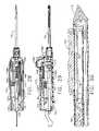
- FIG. 1presents a perspective view of a biopsy device embodying the present invention.
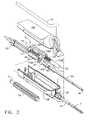
- FIG. 2presents an exploded perspective of the biopsy device illustrated in FIG. 1 .
- FIG. 3presents an exploded perspective, similar to that of FIG. 2 , wherein the component parts of the specimen push rod mechanism is further illustrated as an additional exploded pictorial.
- FIG. 3Apresents a pictorial view of the specimen collection tube and cutter subassembly along with the specimen push rod.
- FIG. 4presents a top view of the biopsy device illustrated in FIG. 1 , having the top cover removed, showing the internal mechanism in its initial starting configuration.
- FIG. 4Apresents a cross-section taken along line 4 A- 4 A in FIG. 4 .
- FIG. 5presents a cross-sectional view taken along line 5 - 5 in FIG. 4 .
- FIG. 6presents a bottom view of the biopsy device illustrated in FIG. 1 , having its bottom cover removed, showing the internal mechanism in its initial starting configuration.
- FIG. 7presents a cross-sectional view of the distal end of the insertion needle illustrating tissue within the specimen sampling recess prior to being sampled.
- FIG. 8presents a top view of the biopsy device, similar to FIG. 4 , showing the internal mechanism with the cutter at the distal end of the insertion needle.
- FIG. 9presents a cross-sectional view taken along line 9 - 9 in FIG. 8 .
- FIG. 10presents a cross-sectional view, similar to FIG. 7 , of the distal end of the insertion needle illustrating a tissue sample within the specimen sampling recess after having been cut.
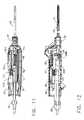
- FIG. 11presents a top view of the biopsy device, similar to FIGS. 4 and 8 , showing the internal mechanism of the biopsy instrument with the cutter and the push rod at their extended distal configuration.
- FIG. 12presents a cross-sectional view, of the biopsy instrument, similar to FIG. 9 , showing the internal mechanism of the biopsy instrument with the cutter and the push rod at their extended distal configuration.
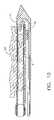
- FIG. 13presents a cross-sectional view, similar to FIGS. 7 and 10 , showing the cut tissue sample having been pushed into the sampling tube by the flexible push rod.
- FIG. 14presents a cross-sectional view showing multiple cut tissue samples having been pushed into the sampling tube by the flexible push rod.
- FIG. 15presents an enlarged view of the area circled in FIG. 13 .
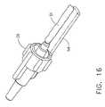
- FIG. 16presents a pictorial view of the vacuum port connector with integral knockout pin.
- FIG. 17presents a pictorial illustration of a specimen board receiving a series of collected specimens discharged, from the sampling tube, in the order that they were taken.
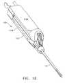
- FIG. 18a perspective view of an alternate embodiment of a biopsy device embodying the present invention.
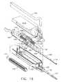
- FIG. 19presents an exploded perspective of the biopsy device illustrated in FIG. 18 .
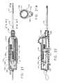
- FIG. 20presents an exploded perspective, similar to that of FIG. 19 , wherein the component parts of the specimen push rod mechanism is further illustrated as an additional exploded pictorial.
- FIG. 20Apresents a pictorial view of the cutter sleeve and cutter subassembly along with the specimen push rod.
- FIG. 21presents a top view of the biopsy device illustrated in FIG. 18 , having the top cover removed, showing the internal mechanism in its initial starting configuration.
- FIG. 21Apresents a cross-section taken along line 21 A- 21 A in FIG. 21 .
- FIG. 22presents a cross-sectional view taken along line 22 - 22 in FIG. 21 .
- FIG. 23presents a bottom view of the biopsy device illustrated in FIG. 18 , having its bottom cover removed, showing the internal mechanism in its initial starting configuration.
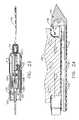
- FIG. 24presents a cross-sectional view of the distal end of the insertion needle illustrating tissue within the specimen sampling recess prior to being sampled.
- FIG. 25presents a top view of the biopsy device, similar to FIG. 21 , showing the internal mechanism with the cutter at the distal end of the insertion needle.
- FIG. 26presents a cross-sectional view taken along line 26 - 26 in FIG. 25 .
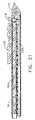
- FIG. 27presents a cross-sectional view, similar to FIG. 24 , of the distal end of the insertion needle illustrating a tissue sample within the cutter after having been cut.
- FIG. 28presents a top view of the biopsy device, similar to FIGS. 21 and 25 , showing the internal mechanism of the biopsy instrument with the cutter and the push rod at their extended distal configuration.
- FIG. 29presents a cross-sectional view, of the biopsy instrument, similar to FIG. 26 , showing the internal mechanism of the biopsy instrument with the cutter and the push rod at their extended distal configuration.
- FIG. 30presents a cross-sectional view, similar to FIGS. 24 and 27 , showing the cut tissue sample having been pushed into the cutter by the flexible push rod.
- FIG. 31presents a cross-sectional view, similar to FIGS. 24 , 27 and 28 , showing multiple cut tissue samples having been sequentially pushed into the cutter by the flexible push rod.
- Biopsy instrument 10comprises an outer housing 12 comprising a top and bottom shell 12 A and 12 B respectively. Extending distally outward from bottom shell 12 B is biopsy needle 15 the function of which will become apparent below. Contained within housing 12 is drive mechanism 16 for operating the specimen cutter 20 and specimen collector tube 25 subassembly, along with specimen push rod 18 as illustrated in FIG. 3A .
- Specimen collection tube 25is coaxially positioned within cutter 20 that in turn is coaxially positioned within the upper lumen 13 of the biopsy needle 15 as illustrated in FIGS. 3 , 3 A, and 4 A.
- Push rod 18is positioned within the lower lumen 19 within biopsy needle 15 as indicated in FIGS. 3 , 3 A, and 4 A.
- a vacuum port connector with knockout pin 26fluidly attached to a vacuum source (not shown), is attached to the proximal end of specimen collection tube 25 , the operation and function of which will be further explained below.
- a vacuum port 28receiving therein vacuum source tube 29 , is provided at the proximal end of needle 15 for providing a vacuum within the lower lumen 19 of biopsy needle 15 . The purpose of providing a vacuum within needle 15 will be further explained below.
- housing 12Also contained within housing 12 is elongated drive gear 14 engaging cutter drive gear 24 , as shown in FIG. 6 , for rotating cutter 20 . Operation of drive mechanism 16 is provided by separately powered worm gear 22 .
- the worm gear threaded portion 22 of drive shaft 30only extends over approximately the middle third of drive shaft 30 ; non threaded portions 32 A and 32 B are provided on the proximal and distal ends of drive shaft 30 respectively, the function of which is further explained below.
- proximal and distal drive blocks 38 A and 38 BPositioned upon drive shaft 30 are proximal and distal drive blocks 38 A and 38 B.
- Elongated rod 40slidingly extends through boss 44 on drive block 38 B and boss 42 of drive block 38 A. End stops 40 A and 40 B is provided at the distal ends of rod 40 , the function of which will be further described below.
- a compression spring 46is axially positioned upon rod 40 between boss 42 and 44 of drive blocks 38 A and 38 B, as best illustrated in FIG. 2 , providing an axial biasing force therebetween.
- the cutter drive mechanism 16When assembled in the biopsy instrument's starting or initial configuration, as illustrated in FIG. 2 , the cutter drive mechanism 16 comprises drive blocks 38 A and 38 B positioned upon worm gear 22 with block 38 A at the far proximal end and block 38 B adjacent thereto.
- block 38 Arests upon the non-threaded portion 32 A of drive shaft 30 and block 38 B is threadingly engaged with worm gear 22 .
- Compression spring 46is fully compressed between bosses 42 and 44 thereby providing a biasing force tending to separate drive blocks 38 A and 38 B.
- drive block 38 Bis threadingly engaged with worm gear 22 and cannot move and block 38 A is being forced against collar 21 at the proximal end of drive shaft 30 the two drive blocks cannot separate.
- Collection tube 25Coaxially positioned within cutter 20 is collection tube 25 , as indicated in FIGS. 3 and 4A .
- Collection tube 25has an engagement feature 25 A that spans over a lip feature 20 A on the proxial end of cutter 20 .
- the engagement feature 25 Aenables the collection tube 25 to advance and retract in unison with the cutter 20 , but as the cutter rotates it allows the collection tube 25 to not rotate.
- the subassembly comprising the cutter and collection tubeis supported by journals 48 A and 48 B, on block 38 B, such that cutter drive gear 24 lies therebetween, as illustrated in FIG. 2 .
- axial movement of drive block 38 B upon worm gear 22also causes axial movement of the subassembly comprising the cutter and the collection tube.
- Cutter drive gear 24remains engaged with elongated drive gear 14 as cutter drive gear 24 advances axially toward the distal end.
- the cutter and collection tubeas a subassembly, is coaxially positioned within needle 15 along with and parallel to the specimen push rod 18 as indicated in FIGS. 3 and 4A .
- Specimen push rod 18is affixed, at its proximal end, to drive block 38 A as illustrated in FIG. 3 .
- drive block 38 Aaxially advances push rod 18 also advances.
- Attached to the proximal end of collection tube 25is vacuum port connector with knockout pin 26 .
- FIGS. 4 , 5 , and 6illustrate the positioning of elements prior to taking a tissue sample.
- Drive blocks 38 A and 38 Bare positioned at their far most proximal location as best illustrated in FIGS. 4 and 5 . In this position the cutter/specimen collection tube subassembly along with the specimen push rod are also positioned at their far most proximal location.
- needle 15is inserted into the tissue to be sampled as illustrated in FIG. 7 .
- a vacuum, supplied from vacuum 29 through port 28is provided inside needle 15 .
- Tissue 50is drawn into specimen port by action of the applied vacuum through orifices 19 in specimen needle 15 .
- Drive shaft 31is rotated thereby rotating cutter 20 through the engagement of cutter drive gear and drive gear 14 .
- Simultaneously drive shaft 30is rotated, rotating worm gear 22 , whereby drive block 38 B advances toward the distal end of the biopsy instrument 10 .
- drive gear 38 Badvances rotating cutter 20 also advances until drive block 38 B runs off worm gear 22 and onto the non-threaded portion 32 B of drive shaft 30 .
- cutter 20will have cut and encapsulated a sample portion of tissue 51 as shown in FIG. 10 .
- end stop 40 B on elongated rod 40has been advanced by the boss 44 of drive block 38 B.
- end stop 40 Acontacts boss 42 of drive block 38 A, see FIGS. 8 and 9 , thereby drawing drive block 38 A onto worm gear 22 .
- coil spring 46is once again placed into a compression mode thereby continuing to bias drive block 38 A and 38 B apart.
- specimen push rod 18also advances, within lower lumen 19 .
- drive block 38 Areaches drive block 38 B, as illustrated in FIGS. 11 and 12 , the sampling operation is ended.
- Drive shaft 30is reversed whereby drive block 38 A engages with the threads on worm gear 22 by the biasing action of the compression spring 46 .
- Drive block 38 Ais returned to its starting position as illustrated in FIG. 8 thereby returning specimen push rod 18 to its starting position.
- elongated rod 40has been retracted by the drive block 38 A.
- end stop 40 Bcontacts boss 44 of drive block 38 B, see FIGS. 8 and 9 , thereby drawing drive block 38 B onto worm gear 22 .
- the cutter 20also retracts.
- the operationmay be repeated to take a second specimen.
- multiple specimens 51 , 51 A, and 51 Bmay be taken and stored in the order taken as illustrated in FIG. 14 .
- collection tube 25may be removed from the biopsy instrument and, using a simple push rod 52 the specimens may be placed upon a specimen holding tray 53 as illustrated in FIG. 17 .
- the single specimen 51may be drawn by vacuum to vacuum port connector 26 with integral knockout pin and withdraw upon an integral specimen catching tray 54 extending from vacuum port connector 26 with integral knockout pin as illustrated in FIG. 16 .
- Biopsy instrument 100comprises an outer housing 112 having a top and bottom shell 112 A and 112 B, respectively. Extending distally outward from bottom shell 112 B is biopsy insertion needle 115 the function of which will become apparent below. Contained within housing 112 is drive mechanism 116 for advancement of hollow tube cutter 120 and specimen push rod 118 . Cutter 120 is coaxially positioned within the upper lumen 113 of the biopsy needle 115 as indicated in FIGS. 20 and 21A Push rod 118 is located within lower lumen 119 within biopsy needle 115 as indicated in FIGS. 20 , 20 A, and 21 A.
- a cutter sleeve 125is located at the proxial end of the cutter to allow the cutter 120 to coaxially slide within the stationary cutter sleeve 125 .
- a vacuum port connector with knockout pin 126fluidly attached to a vacuum source (not shown), is attached to the proximal end of cutter sleeve 125 , the operation and function of which will be further explained below.
- a vacuum port 128receiving therein vacuum source tube 129 , is provided at the proximal end of needle 115 for providing a vacuum within lower lumen 119 of biopsy needle 115 . The purpose of providing a vacuum within needle 115 will be further explained below.
- housing 112Also contained within housing 112 is elongated drive gear 114 engaging cutter drive gear 124 , as shown in FIG. 23 , for rotating cutter 120 . Operation of drive mechanism 116 is provided by separately powered worm gear 122 .
- the worm gear threaded portion 122 of drive shaft 130only extends over approximately the middle third of drive shaft 130 ; non threaded portions 132 A and 132 B are provided on the proximal and distal ends of drive shaft 130 respectively, the function of which is further explained below.
- proximal and distal drive blocks 138 A and 138 BPositioned upon drive shaft 130 are proximal and distal drive blocks 138 A and 138 B.
- Elongated rod 140slidingly extends through boss 144 on drive block 138 B and boss 142 of drive block 138 A. End stops 140 A and 140 B is provided at the distal ends of rod 140 , the function of which will be further described below.
- a compression spring 146is axially positioned upon rod 140 between boss 142 and 144 of drive blocks 138 A and 138 B, as best illustrated in FIG. 20 , providing an axial biasing force therebetween.
- the cutter drive mechanism 116When assembled in the biopsy instrument's starting or initial configuration, as illustrated in FIG. 19 , the cutter drive mechanism 116 comprises drive blocks 138 A and 138 B positioned upon drive shaft 130 with block 138 A at the far proximal end and block 138 B adjacent thereto.
- block 138 Arests upon the non-threaded portion 132 A of drive shaft 130 and block 138 B is threadingly engaged with worm gear 122 .
- Compression spring 146is fully compressed between bosses 142 and 144 thereby providing a maximum biasing force tending to separate drive blocks 138 A and 138 B.
- drive block 138 Bis threadingly engaged with worm gear 122 and cannot move and block 138 A is being forced against collar 121 at the proximal end of drive shaft 130 , the two drive blocks cannot separate.
- the cutter 120is supported by journals 148 A and 148 B, on drive block 138 B, such that cutter drive gear 124 lies therebetween, as illustrated in FIG. 19 .
- axial movement of drive block 138 B upon worm gear 122also causes axial movement of the cutter 120 .
- Cutter drive gear 124remains engaged with elongated drive gear 114 as cutter drive gear 124 advances axially toward the distal end.
- Cutter 120is coaxially positioned within needle 115 along with and parallel to the specimen push rod 118 as indicated in FIGS. 20 and 21A .
- Specimen push rod 118is affixed, at its proximal end, to drive block 138 A as illustrated in FIG. 20 .
- drive block 138 Aaxially advances push rod 118 also advances.
- Attached to the proximal end of cutter sleeve 125is vacuum port connector with knockout pin 126 .
- FIGS. 21 , 22 , and 23illustrate the positioning of elements prior to taking a tissue sample.
- Drive blocks 138 A and 138 Bare positioned at their far most proximal location as best illustrated in FIGS. 19 and 21 . In this position, the cutter/specimen collection tube subassembly along with the specimen push rod are also positioned at their far most proximal location.
- biopsy needle 115is inserted into the tissue to be sampled as illustrated in FIG. 24 .
- a vacuumsupplied from vacuum tube 129 through port 128 , is provided inside needle 115 .
- Tissue 150is drawn into specimen port 117 by action of the applied vacuum through orifices 119 in needle 115 .
- Drive shaft 131is rotated thereby rotating cutter 120 through the engagement of cutter drive gear 124 and drive gear 114 .
- Simultaneously drive shaft 130is rotated, rotating worm gear 122 , whereby drive block 138 B advances toward the distal end of the biopsy instrument 100 .
- rotating cutter 120also advances until drive block 138 B runs off worm gear 122 and onto the non-threaded portion 132 B of drive shaft 130 .
- drive block 138 Breaches its distal end, as illustrated in FIG. 25 , cutter 120 will have cut and encapsulated a sample portion of tissue 151 as shown in FIG. 27 .
- end stop 140 B on elongated rod 140has been advanced by the boss 144 of drive block 138 B.
- end stop 140 Acontacts boss 142 of drive block 138 A, see FIGS. 25 and 26 , thereby drawing drive block 138 A onto worm gear 122 .
- coil spring 146is once again placed into a compression mode thereby continuing to bias drive block 138 A and 138 B apart.
- specimen push rod 118also advances, within lower lumen 119 .
- drive block 138 Areaches drive block 138 B, as illustrated in FIGS. 28 and 29 , the sampling operation is ended.
- Drive shaft 130is reversed whereby drive block 138 A engages with the threads on worm gear 122 by the biasing action of the compression spring 146 .
- Drive block 138 Ais returned to its starting position as illustrated in FIG. 25 , thereby returning specimen push rod 118 to its starting position.
- elongated rod 140has been retracted by the drive block 138 A.
- end stop 140 Bcontacts boss 144 of drive block 138 B, see FIGS. 25 and 26 , thereby drawing drive block 138 B onto worm gear 122 .
- the cutter 120also retracts.
- specimens 151 , 151 A, and 151 Bmay be taken and stored in the order taken as illustrated in FIG. 31 .
- specimens 151 , 151 A, and 151 Bmay be taken and stored in the order taken as illustrated in FIG. 31 .
- the single specimen 151may be drawn by vacuum to vacuum port connector 126 with integral knockout pin and withdraw upon an integral specimen catching tray extending from vacuum port connector 126 with integral knockout pin.
Landscapes
- Health & Medical Sciences (AREA)
- Life Sciences & Earth Sciences (AREA)
- Surgery (AREA)
- Animal Behavior & Ethology (AREA)
- Biomedical Technology (AREA)
- Heart & Thoracic Surgery (AREA)
- Medical Informatics (AREA)
- Molecular Biology (AREA)
- Pathology (AREA)
- Engineering & Computer Science (AREA)
- General Health & Medical Sciences (AREA)
- Public Health (AREA)
- Veterinary Medicine (AREA)
- Sampling And Sample Adjustment (AREA)
- Surgical Instruments (AREA)
- Analysing Materials By The Use Of Radiation (AREA)
Abstract
Description
Claims (15)
Priority Applications (8)
| Application Number | Priority Date | Filing Date | Title |
|---|---|---|---|
| US10/676,944US7419472B2 (en) | 2003-09-30 | 2003-09-30 | Biopsy instrument with internal specimen collection mechanism |
| CA002482581ACA2482581A1 (en) | 2003-09-30 | 2004-09-27 | Biopsy instrument with internal specimen collection mechanism |
| JP2004284751AJP4554319B2 (en) | 2003-09-30 | 2004-09-29 | Biopsy instrument with sample collection mechanism inside |
| AU2004216612AAU2004216612B2 (en) | 2003-09-30 | 2004-09-29 | Biopsy instrument with internal specimen collection mechanism |
| CNA2004100905058ACN1679449A (en) | 2003-09-30 | 2004-09-30 | Biopsy instrument with internal specimen collection mechanism |
| KR1020040080152AKR20050032018A (en) | 2003-09-30 | 2004-09-30 | Biopsy instrument with internal specimen collection mechanism |
| DE602004006931TDE602004006931T2 (en) | 2003-09-30 | 2004-09-30 | Biopsy device with internal sampling mechanism |
| EP04256067AEP1520518B1 (en) | 2003-09-30 | 2004-09-30 | Biopsy instrument with internal specimen collection mechanism |
Applications Claiming Priority (1)
| Application Number | Priority Date | Filing Date | Title |
|---|---|---|---|
| US10/676,944US7419472B2 (en) | 2003-09-30 | 2003-09-30 | Biopsy instrument with internal specimen collection mechanism |
Publications (2)
| Publication Number | Publication Date |
|---|---|
| US20050215921A1 US20050215921A1 (en) | 2005-09-29 |
| US7419472B2true US7419472B2 (en) | 2008-09-02 |
Family
ID=34314045
Family Applications (1)
| Application Number | Title | Priority Date | Filing Date |
|---|---|---|---|
| US10/676,944Expired - Fee RelatedUS7419472B2 (en) | 2003-09-30 | 2003-09-30 | Biopsy instrument with internal specimen collection mechanism |
Country Status (8)
| Country | Link |
|---|---|
| US (1) | US7419472B2 (en) |
| EP (1) | EP1520518B1 (en) |
| JP (1) | JP4554319B2 (en) |
| KR (1) | KR20050032018A (en) |
| CN (1) | CN1679449A (en) |
| AU (1) | AU2004216612B2 (en) |
| CA (1) | CA2482581A1 (en) |
| DE (1) | DE602004006931T2 (en) |
Cited By (57)
| Publication number | Priority date | Publication date | Assignee | Title |
|---|---|---|---|---|
| US20040153003A1 (en)* | 2002-12-11 | 2004-08-05 | Chris Cicenas | Biopsy device with sample tube |
| US20070032741A1 (en)* | 2005-08-05 | 2007-02-08 | Hibner John A | Biopsy device with replaceable probe and incorporating vibration insertion assist and static vacuum source sample stacking retrieval |
| US20070208271A1 (en)* | 2006-03-03 | 2007-09-06 | Voegele James W | Biopsy method |
| US20070213755A1 (en)* | 2006-03-07 | 2007-09-13 | Beckman Andrew T | Device for minimally invasive internal tissue removal |
| US20100113973A1 (en)* | 2005-08-05 | 2010-05-06 | Ethicon Endo-Surgery, Inc. | Biopsy Device with Rotatable Tissue Sample Holder |
| US20100113971A1 (en)* | 2005-08-05 | 2010-05-06 | Ethicon Endo-Surgery, Inc. | Biopsy Device with Translating Valve Mechanism |
| US20110092916A1 (en)* | 2008-12-02 | 2011-04-21 | Allergan, Inc. | Injection device |
| USD637287S1 (en)* | 2009-10-30 | 2011-05-03 | Allergan, Inc. | Combination handheld delivery device and controller unit |
| US20110105947A1 (en)* | 2009-10-30 | 2011-05-05 | Wilson-Cook Medical Inc. | System and method for performing a full thickness tissue biopsy |
| US20110137286A1 (en)* | 2008-05-30 | 2011-06-09 | Allergan, Inc. | Injection device for soft-tissue augmentation fillers, bioactive agents and other biocompatible materials in liquid or gel form |
| US8287466B2 (en) | 2005-03-04 | 2012-10-16 | Devicor Medical Products, Inc. | Biopsy device with variable side aperture |
| US8454532B2 (en) | 2007-12-27 | 2013-06-04 | Devicor Medical Products, Inc. | Clutch and valving system for tetherless biopsy device |
| US8603028B2 (en) | 2011-11-18 | 2013-12-10 | Allergan, Inc. | Injection device having an angled tip portion |
| US8702623B2 (en) | 2008-12-18 | 2014-04-22 | Devicor Medical Products, Inc. | Biopsy device with discrete tissue chambers |
| WO2014084961A1 (en) | 2012-10-08 | 2014-06-05 | Devicor Medical Products, Inc. | Tissue biopsy device with thumbwheel and sample holder |
| US8888751B2 (en) | 2009-12-07 | 2014-11-18 | Allergan, Inc. | Slotted syringe |
| US8968212B2 (en) | 2006-12-13 | 2015-03-03 | Devicor Medical Products, Inc. | Biopsy device with motorized needle cocking |
| US8992481B2 (en) | 2010-05-19 | 2015-03-31 | Allergan, Inc. | Modular injection device |
| US9095654B2 (en) | 2012-08-14 | 2015-08-04 | Allergan, Inc. | Syringe for mixing and dispensing adipose tissue |
| US9161743B2 (en) | 2005-01-31 | 2015-10-20 | C. R. Bard, Inc. | Quick cycle biopsy system |
| US9173641B2 (en) | 2009-08-12 | 2015-11-03 | C. R. Bard, Inc. | Biopsy apparatus having integrated thumbwheel mechanism for manual rotation of biopsy cannula |
| US9265485B2 (en) | 2004-09-29 | 2016-02-23 | Devicor Medical Products, Inc. | Biopsy device with integral vacuum assist and tissue sample and fluid capturing canister |
| US9282949B2 (en) | 2009-09-01 | 2016-03-15 | Bard Peripheral Vascular, Inc. | Charging station for battery powered biopsy apparatus |
| US9301735B2 (en) | 2012-12-19 | 2016-04-05 | Cook Medical Technologies Llc | Drive system for a biopsy member |
| US9347533B2 (en) | 2012-07-25 | 2016-05-24 | Cook Medical Technologies Llc | Rotational drive system for a biopsy member |
| US9345458B2 (en) | 2004-07-09 | 2016-05-24 | Bard Peripheral Vascular, Inc. | Transport system for biopsy device |
| USRE46135E1 (en) | 2005-08-05 | 2016-09-06 | Devicor Medical Products, Inc. | Vacuum syringe assisted biopsy device |
| US9433403B2 (en) | 2007-11-20 | 2016-09-06 | Devicor Medical Products, Inc. | Icon-based user interface on biopsy system control module |
| US9439632B2 (en) | 2006-08-21 | 2016-09-13 | C. R. Bard, Inc. | Self-contained handheld biopsy needle |
| US9439631B2 (en) | 2002-03-19 | 2016-09-13 | C. R. Bard, Inc. | Biopsy device and insertable biopsy needle module |
| US9462999B2 (en) | 2006-12-13 | 2016-10-11 | Devicor Medical Products, Inc. | Biopsy sample storage |
| US9566045B2 (en) | 2006-10-06 | 2017-02-14 | Bard Peripheral Vascular, Inc. | Tissue handling system with reduced operator exposure |
| US9724073B2 (en) | 2012-04-16 | 2017-08-08 | Jeff M. Hathaway | Biopsy device |
| US9775588B2 (en) | 2007-12-20 | 2017-10-03 | C. R. Bard, Inc. | Biopsy device |
| US9901325B2 (en) | 2004-09-29 | 2018-02-27 | Devicor Medical Products, Inc. | Biopsy device with sample storage |
| US9949726B2 (en) | 2009-09-01 | 2018-04-24 | Bard Peripheral Vscular, Inc. | Biopsy driver assembly having a control circuit for conserving battery power |
| US10010307B2 (en) | 2005-08-10 | 2018-07-03 | C. R. Bard, Inc. | Single-insertion, multiple sampling biopsy device with linear drive |
| US10149664B2 (en) | 2006-10-24 | 2018-12-11 | C. R. Bard, Inc. | Large sample low aspect ratio biopsy needle |
| US10265477B2 (en) | 2013-05-23 | 2019-04-23 | Allergan, Inc. | Mechanical syringe accessory |
| US10285673B2 (en) | 2013-03-20 | 2019-05-14 | Bard Peripheral Vascular, Inc. | Biopsy device |
| US10368849B2 (en) | 2005-08-10 | 2019-08-06 | C. R. Bard, Inc. | Single-insertion, multiple sampling biopsy device usable with various transport systems and integrated markers |
| US10433928B2 (en) | 2015-03-10 | 2019-10-08 | Allergan Pharmaceuticals Holdings (Ireland) Unlimited Company | Multiple needle injector |
| US10456120B2 (en) | 2013-11-05 | 2019-10-29 | C. R. Bard, Inc. | Biopsy device having integrated vacuum |
| US10463350B2 (en) | 2015-05-01 | 2019-11-05 | C. R. Bard, Inc. | Biopsy device |
| US10463349B2 (en) | 2014-11-12 | 2019-11-05 | Koninklijke Philips N.V. | Device for obtaining 3D biopsy |
| USD865948S1 (en) | 2017-03-24 | 2019-11-05 | Allergan, Inc. | Syringe device |
| US10596321B2 (en) | 2016-04-08 | 2020-03-24 | Allergan, Inc. | Aspiration and injection device |
| US10595831B2 (en) | 2012-05-30 | 2020-03-24 | Devicor Medical Products, Inc. | Control for biopsy device |
| US10792021B2 (en) | 2014-04-10 | 2020-10-06 | Hee Boong Park | Biopsy device and system |
| US10792427B2 (en) | 2014-05-13 | 2020-10-06 | Allergan, Inc. | High force injection devices |
| US11179141B2 (en) | 2006-12-13 | 2021-11-23 | Devicor Medical Products, Inc. | Biopsy system |
| US20210367478A1 (en)* | 2013-06-26 | 2021-11-25 | Corindus, Inc. | Differential Drive |
| US11185641B2 (en) | 2014-10-01 | 2021-11-30 | Allergan, Inc. | Devices for injection and dosing |
| US11684719B2 (en) | 2013-05-23 | 2023-06-27 | Allergan, Inc. | Methods of treatment using a syringe extrusion accessory |
| US11896261B2 (en) | 2014-11-14 | 2024-02-13 | Cytrellis Biosystems, Inc. | Devices and methods for ablation of the skin |
| US12023226B2 (en) | 2013-02-20 | 2024-07-02 | Cytrellis Biosystems, Inc. | Methods and devices for skin tightening |
| US12064096B2 (en) | 2020-12-30 | 2024-08-20 | Medical Park Co., Ltd. | Needle guide device for biopsy |
Families Citing this family (89)
| Publication number | Priority date | Publication date | Assignee | Title |
|---|---|---|---|---|
| US8109885B2 (en) | 2002-03-19 | 2012-02-07 | C. R. Bard, Inc. | Biopsy device for removing tissue specimens using a vacuum |
| US11337728B2 (en) | 2002-05-31 | 2022-05-24 | Teleflex Life Sciences Limited | Powered drivers, intraosseous devices and methods to access bone marrow |
| US7811260B2 (en) | 2002-05-31 | 2010-10-12 | Vidacare Corporation | Apparatus and method to inject fluids into bone marrow and other target sites |
| US7850620B2 (en) | 2002-05-31 | 2010-12-14 | Vidacare Corporation | Biopsy devices and related methods |
| US11298202B2 (en) | 2002-05-31 | 2022-04-12 | Teleflex Life Sciences Limited | Biopsy devices and related methods |
| US8668698B2 (en) | 2002-05-31 | 2014-03-11 | Vidacare Corporation | Assembly for coupling powered driver with intraosseous device |
| US20070049945A1 (en) | 2002-05-31 | 2007-03-01 | Miller Larry J | Apparatus and methods to install, support and/or monitor performance of intraosseous devices |
| US7951089B2 (en) | 2002-05-31 | 2011-05-31 | Vidacare Corporation | Apparatus and methods to harvest bone and bone marrow |
| US10973545B2 (en) | 2002-05-31 | 2021-04-13 | Teleflex Life Sciences Limited | Powered drivers, intraosseous devices and methods to access bone marrow |
| US8641715B2 (en) | 2002-05-31 | 2014-02-04 | Vidacare Corporation | Manual intraosseous device |
| EP2039298B1 (en) | 2002-05-31 | 2017-10-25 | Vidacare LLC | Apparatus to access bone marrow |
| US8690791B2 (en) | 2002-05-31 | 2014-04-08 | Vidacare Corporation | Apparatus and method to access the bone marrow |
| US9072543B2 (en) | 2002-05-31 | 2015-07-07 | Vidacare LLC | Vascular access kits and methods |
| US8142365B2 (en) | 2002-05-31 | 2012-03-27 | Vidacare Corporation | Apparatus and method for accessing the bone marrow of the sternum |
| US9451968B2 (en) | 2002-05-31 | 2016-09-27 | Vidacare LLC | Powered drivers, intraosseous devices and methods to access bone marrow |
| US9314228B2 (en) | 2002-05-31 | 2016-04-19 | Vidacare LLC | Apparatus and method for accessing the bone marrow |
| US10973532B2 (en) | 2002-05-31 | 2021-04-13 | Teleflex Life Sciences Limited | Powered drivers, intraosseous devices and methods to access bone marrow |
| DE10314240B4 (en) | 2003-03-29 | 2025-05-28 | Bard Dublin Itc Ltd. | Pressure generation unit |
| US9504477B2 (en) | 2003-05-30 | 2016-11-29 | Vidacare LLC | Powered driver |
| US8048003B2 (en) | 2003-10-14 | 2011-11-01 | Suros Surgical Systems, Inc. | Vacuum assisted biopsy device |
| US7988642B2 (en) | 2003-10-14 | 2011-08-02 | Suros Surgical Systems, Inc. | Vacuum assisted biopsy device |
| US8357103B2 (en) | 2003-10-14 | 2013-01-22 | Suros Surgical Systems, Inc. | Vacuum assisted biopsy needle set |
| JP4500315B2 (en) | 2003-10-14 | 2010-07-14 | シュロス・サージカル・システムズ・インコーポレーテッド | Vacuum assisted biopsy needle set |
| US20090312817A1 (en)* | 2003-11-26 | 2009-12-17 | Wicab, Inc. | Systems and methods for altering brain and body functions and for treating conditions and diseases of the same |
| CN101536926B (en) | 2004-01-26 | 2012-07-18 | 维达保健公司 | Manual interosseous device |
| US7815642B2 (en) | 2004-01-26 | 2010-10-19 | Vidacare Corporation | Impact-driven intraosseous needle |
| US7740594B2 (en)* | 2004-09-29 | 2010-06-22 | Ethicon Endo-Surgery, Inc. | Cutter for biopsy device |
| US8998848B2 (en) | 2004-11-12 | 2015-04-07 | Vidacare LLC | Intraosseous device and methods for accessing bone marrow in the sternum and other target areas |
| US20060200041A1 (en) | 2005-03-04 | 2006-09-07 | Ethicon Endo-Surgery, Inc. | Biopsy device incorporating an adjustable probe sleeve |
| US20080004545A1 (en) | 2005-08-05 | 2008-01-03 | Garrison William A | Trigger Fired Radial Plate Specimen Retrieval Biopsy Instrument |
| US7896817B2 (en) | 2005-08-05 | 2011-03-01 | Devicor Medical Products, Inc. | Biopsy device with manually rotated sample barrel |
| US7828748B2 (en)* | 2005-08-05 | 2010-11-09 | Devicor Medical Products, Inc. | Vacuum syringe assisted biopsy device |
| JP4991723B2 (en) | 2005-08-10 | 2012-08-01 | シー・アール・バード・インコーポレーテッド | Single insertion multiple sampling biopsy device with integrated marker |
| US7806834B2 (en)* | 2006-03-07 | 2010-10-05 | Devicor Medical Products, Inc. | Device for minimally invasive internal tissue removal |
| EP3189787B1 (en) | 2006-09-12 | 2019-01-09 | Teleflex Medical Devices S.à.r.l. | Medical procedures trays and related methods |
| EP2068743B1 (en) | 2006-09-12 | 2017-03-15 | Vidacare LLC | Medical procedures trays, kits and related methods |
| EP2073728B1 (en) | 2006-09-12 | 2018-11-07 | Teleflex Medical Devices S.à.r.l. | Biopsy device |
| US8944069B2 (en) | 2006-09-12 | 2015-02-03 | Vidacare Corporation | Assemblies for coupling intraosseous (IO) devices to powered drivers |
| US8974410B2 (en) | 2006-10-30 | 2015-03-10 | Vidacare LLC | Apparatus and methods to communicate fluids and/or support intraosseous devices |
| US7938786B2 (en) | 2006-12-13 | 2011-05-10 | Devicor Medical Products, Inc. | Vacuum timing algorithm for biopsy device |
| US7981049B2 (en) | 2006-12-13 | 2011-07-19 | Devicor Medical Products, Inc. | Engagement interface for biopsy system vacuum module |
| US8251916B2 (en) | 2006-12-13 | 2012-08-28 | Devicor Medical Products, Inc. | Revolving tissue sample holder for biopsy device |
| EP1932481B1 (en)* | 2006-12-13 | 2010-06-30 | Ethicon Endo-Surgery, Inc. | Biopsy system with vacuum control module |
| CN101711129B (en)* | 2007-05-17 | 2012-07-04 | 普罗德克斯有限公司 | Handheld medical device |
| US7575556B2 (en)* | 2007-11-20 | 2009-08-18 | Ethicon Endo-Surgery, Inc. | Deployment device interface for biopsy device |
| US9039634B2 (en) | 2007-11-20 | 2015-05-26 | Devicor Medical Products, Inc. | Biopsy device tissue sample holder rotation control |
| US8052616B2 (en) | 2007-11-20 | 2011-11-08 | Devicor Medical Products, Inc. | Biopsy device with fine pitch drive train |
| US7806835B2 (en) | 2007-11-20 | 2010-10-05 | Devicor Medical Products, Inc. | Biopsy device with sharps reduction feature |
| US7858038B2 (en) | 2007-11-20 | 2010-12-28 | Devicor Medical Products, Inc. | Biopsy device with illuminated tissue holder |
| WO2010107424A1 (en)* | 2009-03-16 | 2010-09-23 | C.R. Bard, Inc. | Biopsy device having rotational cutting |
| AU2009344276B2 (en) | 2009-04-15 | 2014-06-05 | C.R. Bard, Inc. | Biopsy apparatus having integrated fluid management |
| US8206316B2 (en) | 2009-06-12 | 2012-06-26 | Devicor Medical Products, Inc. | Tetherless biopsy device with reusable portion |
| US8485989B2 (en) | 2009-09-01 | 2013-07-16 | Bard Peripheral Vascular, Inc. | Biopsy apparatus having a tissue sample retrieval mechanism |
| US8597206B2 (en) | 2009-10-12 | 2013-12-03 | Bard Peripheral Vascular, Inc. | Biopsy probe assembly having a mechanism to prevent misalignment of components prior to installation |
| ES2755510T3 (en)* | 2010-01-11 | 2020-04-22 | Pro Dex Inc | Thermal Filled Handheld Medical Device |
| US9220485B2 (en) | 2010-08-28 | 2015-12-29 | Endochoice, Inc. | Tissue collection and separation device |
| US9968337B2 (en)* | 2010-12-20 | 2018-05-15 | Cook Medical Technologies Llc | Coring tissue biopsy needle and method of use |
| EP2667805B1 (en) | 2011-01-28 | 2023-04-05 | The General Hospital Corporation | Apparatus and method for tissue biopsy |
| MX347856B (en)* | 2011-01-28 | 2017-05-16 | Massachusetts Gen Hospital | Method and apparatus for skin resurfacing. |
| ES2833525T3 (en) | 2011-07-21 | 2021-06-15 | Massachusetts Gen Hospital | Apparatus for deteriorating and removing grease |
| KR101147564B1 (en) | 2012-01-03 | 2012-05-21 | 권혁호 | Pen type device for ultrasound guided fine needle aspiration cytology and biopsy |
| KR101275917B1 (en)* | 2012-02-16 | 2013-06-17 | 권혁호 | Dual purpose pen type device for ultrasound guided fine needle aspiration and core needle biopsy |
| AU2014306273B2 (en) | 2013-08-09 | 2019-07-11 | Cytrellis Biosystems, Inc. | Methods and apparatuses for skin treatment using non-thermal tissue ablation |
| US10953143B2 (en) | 2013-12-19 | 2021-03-23 | Cytrellis Biosystems, Inc. | Methods and devices for manipulating subdermal fat |
| US10390806B2 (en)* | 2014-03-28 | 2019-08-27 | Covidien Lp | Devices, systems, and methods for obtaining a tissue sample using a biopsy tool |
| US10695038B2 (en) | 2015-04-20 | 2020-06-30 | Covidien Lp | Devices, systems, and methods for obtaining a tissue sample |
| KR102561605B1 (en) | 2016-03-29 | 2023-08-01 | 사이트렐리스 바이오시스템즈, 인크. | Device and method for cosmetic skin resurfacing |
| CN109922740B (en) | 2016-09-21 | 2022-08-23 | 希特利斯生物系统有限公司 | Device and method for cosmetic skin reconstruction |
| CA3040275A1 (en)* | 2016-10-12 | 2018-04-19 | Devicor Medical Products, Inc. | Core needle biopsy device for collecting multiple samples in a single insertion |
| US11160538B2 (en)* | 2016-10-31 | 2021-11-02 | Devicor Medical Products, Inc. | Biopsy device with linear actuator |
| EP3544518B1 (en)* | 2016-11-23 | 2025-10-15 | C. R. Bard, Inc. | Single insertion multiple sample biopsy apparatus |
| US11844500B2 (en) | 2017-05-19 | 2023-12-19 | Merit Medical Systems, Inc. | Semi-automatic biopsy needle device and methods of use |
| US11793498B2 (en) | 2017-05-19 | 2023-10-24 | Merit Medical Systems, Inc. | Biopsy needle devices and methods of use |
| US11116483B2 (en) | 2017-05-19 | 2021-09-14 | Merit Medical Systems, Inc. | Rotating biopsy needle |
| EP3578111A1 (en)* | 2018-06-04 | 2019-12-11 | TeesuVac ApS | Tissue collection device for collection of tissue samples from a biopsy needle and biopsy device including tissue collection device |
| CN109288544B (en)* | 2018-10-17 | 2024-08-27 | 荷塘探索国际健康科技发展(北京)有限公司 | Tissue sample collection device and medical instrument |
| CN110384524B (en)* | 2019-08-20 | 2022-09-23 | 兰州大学第一医院 | Alimentary canal tumour biopsy sampler |
| US12295556B2 (en) | 2019-09-27 | 2025-05-13 | Merit Medical Systems, Inc. | Rotation biopsy system and handle |
| WO2021076753A2 (en)* | 2019-10-17 | 2021-04-22 | Devicor Medical Products, Inc. | Sample management for core needle biopsy device |
| US12150627B2 (en) | 2019-12-11 | 2024-11-26 | Merit Medical Systems, Inc. | Bone biopsy device and related methods |
| CN111281443B (en)* | 2020-03-12 | 2022-07-05 | 西安瑞丰仪器设备有限责任公司 | ESD sample automatic processing equipment and method |
| CN114366880A (en)* | 2022-03-01 | 2022-04-19 | 深圳市宝安区妇幼保健院 | Medical ovarian tumor imbibition device |
| CN115500872A (en)* | 2022-08-25 | 2022-12-23 | 浙江伽奈维医疗科技有限公司 | Plasma mammary gland sampling biopsy device |
| CN115624372B (en)* | 2022-12-15 | 2023-04-07 | 北京新云医疗科技有限公司 | Surgical instrument |
| CN115778511B (en)* | 2023-02-03 | 2023-04-07 | 深圳市亿康医疗技术有限公司 | Thoracoscope surgery positioning device |
| CN115836885B (en)* | 2023-02-28 | 2023-05-05 | 吉林大学 | Tumor biopsy forceps |
| CN116602768B (en)* | 2023-05-16 | 2025-09-16 | 哈尔滨工业大学 | Parallel handheld prostate biopsy robot with telecentric fixed point structure |
| CN116784892B (en)* | 2023-05-22 | 2023-11-03 | 南昌大学第一附属医院 | Automatic synovial biopsy sampling combined device and application method thereof |
| CN117064456B (en)* | 2023-10-17 | 2024-02-02 | 江西省水产科学研究所(江西省鄱阳湖渔业研究中心、江西省渔业资源生态环境监测中心) | Automatic sampling device for crucian immune tissues |
Citations (8)
| Publication number | Priority date | Publication date | Assignee | Title |
|---|---|---|---|---|
| US5573008A (en)* | 1993-10-29 | 1996-11-12 | Boston Scientific Corporation | Multiple biopsy sampling coring device |
| US5601585A (en) | 1994-02-08 | 1997-02-11 | Boston Scientific Corporation | Multi-motion side-cutting biopsy sampling device |
| US5649547A (en)* | 1994-03-24 | 1997-07-22 | Biopsys Medical, Inc. | Methods and devices for automated biopsy and collection of soft tissue |
| US6019733A (en) | 1997-09-19 | 2000-02-01 | United States Surgical Corporation | Biopsy apparatus and method |
| US6220248B1 (en)* | 1998-10-21 | 2001-04-24 | Ethicon Endo-Surgery, Inc. | Method for implanting a biopsy marker |
| US6432064B1 (en)* | 2001-04-09 | 2002-08-13 | Ethicon Endo-Surgery, Inc. | Biopsy instrument with tissue marking element |
| US6485436B1 (en) | 2000-08-10 | 2002-11-26 | Csaba Truckai | Pressure-assisted biopsy needle apparatus and technique |
| US20020183715A1 (en)* | 2001-04-24 | 2002-12-05 | Mantell Robert R. | Laparoscopic insertion device |
Family Cites Families (16)
| Publication number | Priority date | Publication date | Assignee | Title |
|---|---|---|---|---|
| SE456886B (en) | 1986-02-19 | 1988-11-14 | Radiplast Ab | DEVICE FOR TAPE SAMPLING WITH A NATIONAL DISPENSER |
| SE459635B (en) | 1987-11-19 | 1989-07-24 | Radiplast Ab | DRIVER CONTAINS A DEVICE FOR TAPE SAMPLING |
| USRE34056E (en) | 1989-07-31 | 1992-09-08 | C.R. Bard, Inc. | Tissue sampling device |
| US5027827A (en) | 1990-03-28 | 1991-07-02 | Cody Michael P | Vacuum biopsy apparatus |
| GB2256369B (en) | 1991-06-04 | 1995-10-25 | Chiou Rei Kwen | Improved biopsy device |
| US5526821A (en) | 1993-06-03 | 1996-06-18 | Medical Biopsy, Inc. | Biopsy needle with sample retaining means |
| US5429138A (en) | 1993-06-03 | 1995-07-04 | Kormed, Inc. | Biopsy needle with sample retaining means |
| CA2287087C (en) | 1998-10-23 | 2007-12-04 | Ethicon Endo-Surgery, Inc. | Surgical device for the collection of soft tissue |
| US6656133B2 (en)* | 2000-10-13 | 2003-12-02 | Ethicon Endo-Surgery, Inc. | Transmission assembly for a surgical biopsy device |
| US20030199753A1 (en)* | 2002-04-23 | 2003-10-23 | Ethicon Endo-Surgery | MRI compatible biopsy device with detachable probe |
| US7769426B2 (en)* | 2002-04-23 | 2010-08-03 | Ethicon Endo-Surgery, Inc. | Method for using an MRI compatible biopsy device with detachable probe |
| US7826883B2 (en)* | 2002-04-23 | 2010-11-02 | Devicor Medical Products, Inc. | Localization mechanism for an MRI compatible biopsy device |
| US7740597B2 (en)* | 2002-12-11 | 2010-06-22 | Ethicon Endo-Surgery, Inc. | Biopsy device with sample tube |
| US7169115B2 (en)* | 2003-09-29 | 2007-01-30 | Ethicon Endo-Surgery, Inc. | Endoscopic mucosal resection device with overtube and method of use |
| US6994705B2 (en)* | 2003-09-29 | 2006-02-07 | Ethicon-Endo Surgery, Inc. | Endoscopic mucosal resection device with conductive tissue stop |
| US7186252B2 (en)* | 2003-09-29 | 2007-03-06 | Ethicon Endo-Surgery, Inc. | Endoscopic mucosal resection device and method of use |
- 2003
- 2003-09-30USUS10/676,944patent/US7419472B2/ennot_activeExpired - Fee Related
- 2004
- 2004-09-27CACA002482581Apatent/CA2482581A1/ennot_activeAbandoned
- 2004-09-29JPJP2004284751Apatent/JP4554319B2/ennot_activeExpired - Fee Related
- 2004-09-29AUAU2004216612Apatent/AU2004216612B2/ennot_activeCeased
- 2004-09-30CNCNA2004100905058Apatent/CN1679449A/enactivePending
- 2004-09-30EPEP04256067Apatent/EP1520518B1/ennot_activeExpired - Lifetime
- 2004-09-30DEDE602004006931Tpatent/DE602004006931T2/ennot_activeExpired - Lifetime
- 2004-09-30KRKR1020040080152Apatent/KR20050032018A/ennot_activeCeased
Patent Citations (9)
| Publication number | Priority date | Publication date | Assignee | Title |
|---|---|---|---|---|
| US5573008A (en)* | 1993-10-29 | 1996-11-12 | Boston Scientific Corporation | Multiple biopsy sampling coring device |
| US5601585A (en) | 1994-02-08 | 1997-02-11 | Boston Scientific Corporation | Multi-motion side-cutting biopsy sampling device |
| US5649547A (en)* | 1994-03-24 | 1997-07-22 | Biopsys Medical, Inc. | Methods and devices for automated biopsy and collection of soft tissue |
| US6428486B2 (en)* | 1994-03-24 | 2002-08-06 | Ethicon Endo-Surgery, Inc. | Methods and devices for automated biopsy and collection of soft tissue |
| US6019733A (en) | 1997-09-19 | 2000-02-01 | United States Surgical Corporation | Biopsy apparatus and method |
| US6220248B1 (en)* | 1998-10-21 | 2001-04-24 | Ethicon Endo-Surgery, Inc. | Method for implanting a biopsy marker |
| US6485436B1 (en) | 2000-08-10 | 2002-11-26 | Csaba Truckai | Pressure-assisted biopsy needle apparatus and technique |
| US6432064B1 (en)* | 2001-04-09 | 2002-08-13 | Ethicon Endo-Surgery, Inc. | Biopsy instrument with tissue marking element |
| US20020183715A1 (en)* | 2001-04-24 | 2002-12-05 | Mantell Robert R. | Laparoscopic insertion device |
Cited By (119)
| Publication number | Priority date | Publication date | Assignee | Title |
|---|---|---|---|---|
| US10335128B2 (en) | 2002-03-19 | 2019-07-02 | C. R. Bard, Inc. | Biopsy device and insertable biopsy needle module |
| US9439631B2 (en) | 2002-03-19 | 2016-09-13 | C. R. Bard, Inc. | Biopsy device and insertable biopsy needle module |
| US20040153003A1 (en)* | 2002-12-11 | 2004-08-05 | Chris Cicenas | Biopsy device with sample tube |
| US9872672B2 (en) | 2004-07-09 | 2018-01-23 | Bard Peripheral Vascular, Inc. | Length detection system for biopsy device |
| US10499888B2 (en) | 2004-07-09 | 2019-12-10 | Bard Peripheral Vascular, Inc. | Tissue sample flushing system for biopsy device |
| US9456809B2 (en) | 2004-07-09 | 2016-10-04 | Bard Peripheral Vascular, Inc. | Tissue sample flushing system for biopsy device |
| US9345458B2 (en) | 2004-07-09 | 2016-05-24 | Bard Peripheral Vascular, Inc. | Transport system for biopsy device |
| US10166011B2 (en) | 2004-07-09 | 2019-01-01 | Bard Peripheral Vascular, Inc. | Transport system for biopsy device |
| US9757100B2 (en) | 2004-09-29 | 2017-09-12 | Devicor Medical Products, Inc. | Biopsy device with integral vacuum assist and tissue sample and fluid capturing canister |
| US9468425B2 (en) | 2004-09-29 | 2016-10-18 | Devicor Medical Products, Inc. | Biopsy device with integral vacuum assist and tissue sample and fluid capturing canister |
| US9901325B2 (en) | 2004-09-29 | 2018-02-27 | Devicor Medical Products, Inc. | Biopsy device with sample storage |
| US9265485B2 (en) | 2004-09-29 | 2016-02-23 | Devicor Medical Products, Inc. | Biopsy device with integral vacuum assist and tissue sample and fluid capturing canister |
| US9161743B2 (en) | 2005-01-31 | 2015-10-20 | C. R. Bard, Inc. | Quick cycle biopsy system |
| US10058308B2 (en) | 2005-01-31 | 2018-08-28 | C. R. Bard, Inc. | Method for operating a biopsy apparatus |
| US11166702B2 (en) | 2005-01-31 | 2021-11-09 | C.R. Bard, Inc. | Quick cycle biopsy system |
| US9095327B2 (en) | 2005-03-04 | 2015-08-04 | Devicor Medical Products, Inc. | Biopsy device with variable side aperture |
| US8287466B2 (en) | 2005-03-04 | 2012-10-16 | Devicor Medical Products, Inc. | Biopsy device with variable side aperture |
| US9668717B2 (en) | 2005-03-04 | 2017-06-06 | Devicor Medical Products, Inc. | Biopsy device with variable side aperture |
| US8979769B2 (en) | 2005-08-05 | 2015-03-17 | Devicor Medical Products, Inc. | Biopsy device with vacuum assisted bleeding control |
| US20110071433A1 (en)* | 2005-08-05 | 2011-03-24 | Devicor Medical Products, Inc. | Biopsy device with translating valve member |
| US9901327B2 (en) | 2005-08-05 | 2018-02-27 | Devicor Medical Products, Inc. | Biopsy device with translating valve member |
| US8568335B2 (en) | 2005-08-05 | 2013-10-29 | Devicor Medical Products, Inc. | Biopsy device with vacuum assisted bleeding control |
| US8241226B2 (en) | 2005-08-05 | 2012-08-14 | Devicor Medical Products, Inc. | Biopsy device with rotatable tissue sample holder |
| US20070032741A1 (en)* | 2005-08-05 | 2007-02-08 | Hibner John A | Biopsy device with replaceable probe and incorporating vibration insertion assist and static vacuum source sample stacking retrieval |
| US9907542B2 (en) | 2005-08-05 | 2018-03-06 | Devicor Medical Products, Inc. | Biopsy device with translating valve member |
| US9968339B2 (en) | 2005-08-05 | 2018-05-15 | Devicor Medical Products, Inc. | Biopsy device with rotatable tissue sample holder |
| US20100113973A1 (en)* | 2005-08-05 | 2010-05-06 | Ethicon Endo-Surgery, Inc. | Biopsy Device with Rotatable Tissue Sample Holder |
| US8235913B2 (en) | 2005-08-05 | 2012-08-07 | Devicor Medical Products, Inc. | Biopsy device with translating valve member |
| US8905943B2 (en) | 2005-08-05 | 2014-12-09 | Devicor Medical Products, Inc. | Biopsy device with rotatable tissue sample holder |
| US8911381B2 (en) | 2005-08-05 | 2014-12-16 | Devicor Medical Products, Inc. | Biopsy device with translating valve member |
| US20100113971A1 (en)* | 2005-08-05 | 2010-05-06 | Ethicon Endo-Surgery, Inc. | Biopsy Device with Translating Valve Mechanism |
| US8038627B2 (en) | 2005-08-05 | 2011-10-18 | Devicor Medical Products, Inc. | Biopsy device with translating valve mechanism |
| USRE46135E1 (en) | 2005-08-05 | 2016-09-06 | Devicor Medical Products, Inc. | Vacuum syringe assisted biopsy device |
| US9005136B2 (en) | 2005-08-05 | 2015-04-14 | Devicor Medical Products, Inc. | Biopsy device with vacuum assisted bleeding control |
| US20110144532A1 (en)* | 2005-08-05 | 2011-06-16 | Devicor Medical Products, Inc. | Biopsy device with vacuum assisted bleeding control |
| US11224412B2 (en) | 2005-08-05 | 2022-01-18 | Devicor Medical Products, Inc. | Biopsy device with translating valve member |
| US9414814B2 (en) | 2005-08-05 | 2016-08-16 | Devicor Medical Products, Inc. | Biopsy device with rotatable tissue sample holder |
| US7867173B2 (en) | 2005-08-05 | 2011-01-11 | Devicor Medical Products, Inc. | Biopsy device with replaceable probe and incorporating vibration insertion assist and static vacuum source sample stacking retrieval |
| US11849928B2 (en) | 2005-08-10 | 2023-12-26 | C. R. Bard, Inc. | Single-insertion, multiple sampling biopsy device usable with various transport systems and integrated markers |
| US10010307B2 (en) | 2005-08-10 | 2018-07-03 | C. R. Bard, Inc. | Single-insertion, multiple sampling biopsy device with linear drive |
| US10368849B2 (en) | 2005-08-10 | 2019-08-06 | C. R. Bard, Inc. | Single-insertion, multiple sampling biopsy device usable with various transport systems and integrated markers |
| US11219431B2 (en) | 2005-08-10 | 2022-01-11 | C.R. Bard, Inc. | Single-insertion, multiple sampling biopsy device with linear drive |
| US20070208271A1 (en)* | 2006-03-03 | 2007-09-06 | Voegele James W | Biopsy method |
| US7766843B2 (en) | 2006-03-03 | 2010-08-03 | Ethicon Endo-Surgery, Inc. | Biopsy method |
| US20070213755A1 (en)* | 2006-03-07 | 2007-09-13 | Beckman Andrew T | Device for minimally invasive internal tissue removal |
| US7670299B2 (en) | 2006-03-07 | 2010-03-02 | Ethincon Endo-Surgery, Inc. | Device for minimally invasive internal tissue removal |
| US10617399B2 (en) | 2006-08-21 | 2020-04-14 | C.R. Bard, Inc. | Self-contained handheld biopsy needle |
| US9439632B2 (en) | 2006-08-21 | 2016-09-13 | C. R. Bard, Inc. | Self-contained handheld biopsy needle |
| US9566045B2 (en) | 2006-10-06 | 2017-02-14 | Bard Peripheral Vascular, Inc. | Tissue handling system with reduced operator exposure |
| US11559289B2 (en) | 2006-10-06 | 2023-01-24 | Bard Peripheral Vascular, Inc. | Tissue handling system with reduced operator exposure |
| US10172594B2 (en) | 2006-10-06 | 2019-01-08 | Bard Peripheral Vascular, Inc. | Tissue handling system with reduced operator exposure |
| US11583261B2 (en) | 2006-10-24 | 2023-02-21 | C. R. Bard, Inc. | Large sample low aspect ratio biopsy needle |
| US10149664B2 (en) | 2006-10-24 | 2018-12-11 | C. R. Bard, Inc. | Large sample low aspect ratio biopsy needle |
| US9974523B2 (en) | 2006-12-13 | 2018-05-22 | Devicor Medical Products, Inc. | Biopsy sample storage |
| US9486184B2 (en) | 2006-12-13 | 2016-11-08 | Devicor Medical Products, Inc. | Biopsy sample storage |
| US8968212B2 (en) | 2006-12-13 | 2015-03-03 | Devicor Medical Products, Inc. | Biopsy device with motorized needle cocking |
| US10517577B2 (en) | 2006-12-13 | 2019-12-31 | Devicor Medical Products, Inc. | Presentation of biopsy sample by biopsy device |
| US10905403B2 (en) | 2006-12-13 | 2021-02-02 | Devicor Medical Products, Inc. | Presentation of biopsy sample by biopsy device |
| US9462999B2 (en) | 2006-12-13 | 2016-10-11 | Devicor Medical Products, Inc. | Biopsy sample storage |
| US10966691B2 (en) | 2006-12-13 | 2021-04-06 | Devicor Medical Products, Inc. | Biopsy sample storage |
| US11179141B2 (en) | 2006-12-13 | 2021-11-23 | Devicor Medical Products, Inc. | Biopsy system |
| US9433403B2 (en) | 2007-11-20 | 2016-09-06 | Devicor Medical Products, Inc. | Icon-based user interface on biopsy system control module |
| US9775588B2 (en) | 2007-12-20 | 2017-10-03 | C. R. Bard, Inc. | Biopsy device |
| US10687791B2 (en) | 2007-12-20 | 2020-06-23 | C. R. Bard, Inc. | Biopsy device |
| US8454532B2 (en) | 2007-12-27 | 2013-06-04 | Devicor Medical Products, Inc. | Clutch and valving system for tetherless biopsy device |
| US8864682B2 (en) | 2007-12-27 | 2014-10-21 | Devicor Medical Products, Inc. | Clutch and valving system for tetherless biopsy device |
| US20110137286A1 (en)* | 2008-05-30 | 2011-06-09 | Allergan, Inc. | Injection device for soft-tissue augmentation fillers, bioactive agents and other biocompatible materials in liquid or gel form |
| US10279162B2 (en) | 2008-05-30 | 2019-05-07 | Allergan, Inc. | Injection device for soft-tissue augmentation fillers, bioactive agents and other biocompatible materials in liquid or gel form |
| US8801659B2 (en) | 2008-05-30 | 2014-08-12 | Allergan, Inc. | Injection device for soft-tissue augmentation fillers, bioactive agents and other biocompatible materials in liquid or gel form |
| US20110092916A1 (en)* | 2008-12-02 | 2011-04-21 | Allergan, Inc. | Injection device |
| US10232129B2 (en) | 2008-12-02 | 2019-03-19 | Allergan, Inc. | Injection device |
| US11992668B2 (en) | 2008-12-02 | 2024-05-28 | Allergan, Inc. | Injection device |
| US8702623B2 (en) | 2008-12-18 | 2014-04-22 | Devicor Medical Products, Inc. | Biopsy device with discrete tissue chambers |
| US9173641B2 (en) | 2009-08-12 | 2015-11-03 | C. R. Bard, Inc. | Biopsy apparatus having integrated thumbwheel mechanism for manual rotation of biopsy cannula |
| US9655599B2 (en) | 2009-08-12 | 2017-05-23 | C. R. Bard, Inc. | Biopsy apparatus having integrated thumbwheel mechanism for manual rotation of biopsy cannula |
| US10575833B2 (en) | 2009-08-12 | 2020-03-03 | C. R. Bard, Inc. | Biopsy apparatus having integrated thumbwheel mechanism for manual rotation of biopsy cannula |
| US9282949B2 (en) | 2009-09-01 | 2016-03-15 | Bard Peripheral Vascular, Inc. | Charging station for battery powered biopsy apparatus |
| US9949726B2 (en) | 2009-09-01 | 2018-04-24 | Bard Peripheral Vscular, Inc. | Biopsy driver assembly having a control circuit for conserving battery power |
| US20110105947A1 (en)* | 2009-10-30 | 2011-05-05 | Wilson-Cook Medical Inc. | System and method for performing a full thickness tissue biopsy |
| USD637287S1 (en)* | 2009-10-30 | 2011-05-03 | Allergan, Inc. | Combination handheld delivery device and controller unit |
| US8506503B2 (en) | 2009-10-30 | 2013-08-13 | Cook Medical Technologies Llc | System and method for performing a full thickness tissue biopsy |
| US8888751B2 (en) | 2009-12-07 | 2014-11-18 | Allergan, Inc. | Slotted syringe |
| US8992481B2 (en) | 2010-05-19 | 2015-03-31 | Allergan, Inc. | Modular injection device |
| US8603028B2 (en) | 2011-11-18 | 2013-12-10 | Allergan, Inc. | Injection device having an angled tip portion |
| US9468720B2 (en) | 2011-11-18 | 2016-10-18 | Allergan, Inc. | Injection device having an angled tip portion |
| US9724073B2 (en) | 2012-04-16 | 2017-08-08 | Jeff M. Hathaway | Biopsy device |
| US10595831B2 (en) | 2012-05-30 | 2020-03-24 | Devicor Medical Products, Inc. | Control for biopsy device |
| US9347533B2 (en) | 2012-07-25 | 2016-05-24 | Cook Medical Technologies Llc | Rotational drive system for a biopsy member |
| US9095654B2 (en) | 2012-08-14 | 2015-08-04 | Allergan, Inc. | Syringe for mixing and dispensing adipose tissue |
| WO2014084961A1 (en) | 2012-10-08 | 2014-06-05 | Devicor Medical Products, Inc. | Tissue biopsy device with thumbwheel and sample holder |
| US9474511B2 (en) | 2012-10-08 | 2016-10-25 | Devicor Medical Products, Inc. | Tissue biopsy device with selectively rotatable linked thumbwheel and tissue sample holder |
| US9980705B2 (en) | 2012-10-08 | 2018-05-29 | Devicor Medical Products, Inc. | Tissue biopsy device with selectively rotatably linked thumbwheel and tissue sample holder |
| US9301735B2 (en) | 2012-12-19 | 2016-04-05 | Cook Medical Technologies Llc | Drive system for a biopsy member |
| US12023226B2 (en) | 2013-02-20 | 2024-07-02 | Cytrellis Biosystems, Inc. | Methods and devices for skin tightening |
| US11779316B2 (en) | 2013-03-20 | 2023-10-10 | Bard Peripheral Vascular, Inc. | Biopsy device |
| US10285673B2 (en) | 2013-03-20 | 2019-05-14 | Bard Peripheral Vascular, Inc. | Biopsy device |
| US11684719B2 (en) | 2013-05-23 | 2023-06-27 | Allergan, Inc. | Methods of treatment using a syringe extrusion accessory |
| US10265477B2 (en) | 2013-05-23 | 2019-04-23 | Allergan, Inc. | Mechanical syringe accessory |
| US20210367478A1 (en)* | 2013-06-26 | 2021-11-25 | Corindus, Inc. | Differential Drive |
| US12136867B2 (en)* | 2013-06-26 | 2024-11-05 | Corindus, Inc. | Differential drive |
| US11534148B2 (en) | 2013-11-05 | 2022-12-27 | C. R. Bard, Inc. | Biopsy device having integrated vacuum |
| US10456120B2 (en) | 2013-11-05 | 2019-10-29 | C. R. Bard, Inc. | Biopsy device having integrated vacuum |
| US10792021B2 (en) | 2014-04-10 | 2020-10-06 | Hee Boong Park | Biopsy device and system |
| US10792427B2 (en) | 2014-05-13 | 2020-10-06 | Allergan, Inc. | High force injection devices |
| US11185641B2 (en) | 2014-10-01 | 2021-11-30 | Allergan, Inc. | Devices for injection and dosing |
| US10463349B2 (en) | 2014-11-12 | 2019-11-05 | Koninklijke Philips N.V. | Device for obtaining 3D biopsy |
| US11896261B2 (en) | 2014-11-14 | 2024-02-13 | Cytrellis Biosystems, Inc. | Devices and methods for ablation of the skin |
| US12256957B2 (en) | 2014-11-14 | 2025-03-25 | Cytrellis Biosystems, Inc. | Devices and methods for ablation of the skin |
| US10433928B2 (en) | 2015-03-10 | 2019-10-08 | Allergan Pharmaceuticals Holdings (Ireland) Unlimited Company | Multiple needle injector |
| US11179142B2 (en) | 2015-05-01 | 2021-11-23 | C.R. Bard, Inc. | Biopsy device |
| US10463350B2 (en) | 2015-05-01 | 2019-11-05 | C. R. Bard, Inc. | Biopsy device |
| US10596321B2 (en) | 2016-04-08 | 2020-03-24 | Allergan, Inc. | Aspiration and injection device |
| US11890457B2 (en) | 2016-04-08 | 2024-02-06 | Allergan, Inc. | Aspiration and injection device |
| USD867582S1 (en) | 2017-03-24 | 2019-11-19 | Allergan, Inc. | Syringe device |
| USD865950S1 (en) | 2017-03-24 | 2019-11-05 | Allergan, Inc. | Syringe device |
| USD865949S1 (en) | 2017-03-24 | 2019-11-05 | Allergan, Inc. | Syringe device |
| USD866753S1 (en) | 2017-03-24 | 2019-11-12 | Allergan, Inc. | Syringe device |
| USD865948S1 (en) | 2017-03-24 | 2019-11-05 | Allergan, Inc. | Syringe device |
| US12064096B2 (en) | 2020-12-30 | 2024-08-20 | Medical Park Co., Ltd. | Needle guide device for biopsy |
Also Published As
| Publication number | Publication date |
|---|---|
| JP4554319B2 (en) | 2010-09-29 |
| AU2004216612A1 (en) | 2005-04-14 |
| AU2004216612B2 (en) | 2009-09-24 |
| JP2005103276A (en) | 2005-04-21 |
| DE602004006931D1 (en) | 2007-07-26 |
| DE602004006931T2 (en) | 2008-02-07 |
| CN1679449A (en) | 2005-10-12 |
| CA2482581A1 (en) | 2005-03-30 |
| EP1520518B1 (en) | 2007-06-13 |
| KR20050032018A (en) | 2005-04-06 |
| EP1520518A3 (en) | 2005-05-04 |
| EP1520518A2 (en) | 2005-04-06 |
| US20050215921A1 (en) | 2005-09-29 |
Similar Documents
| Publication | Publication Date | Title |
|---|---|---|
| US7419472B2 (en) | Biopsy instrument with internal specimen collection mechanism | |
| JP3650117B2 (en) | Biopsy device and biopsy instrument for obtaining tissue samples | |
| US8591435B2 (en) | Methods and devices for biopsy and collection of soft tissue | |
| US6942627B2 (en) | Surgical biopsy device having a flexible cutter | |
| US5964716A (en) | Method of use for a multi-port biopsy instrument | |
| US6077230A (en) | Biopsy instrument with removable extractor | |
| EP1093757B1 (en) | Device for collection of soft tissue | |
| US20080146965A1 (en) | Surgical Device for The Collection of Soft Tissue | |
| JP2004508127A (en) | Biopsy system | |
| WO2002062231A2 (en) | Biopsy apparatus and method | |
| WO2002062229A2 (en) | Biopsy apparatus and method |
Legal Events
| Date | Code | Title | Description |
|---|---|---|---|
| AS | Assignment | Owner name:ETHICON ENDO-SURGERY, INC., OHIO Free format text:ASSIGNMENT OF ASSIGNORS INTEREST;ASSIGNORS:HIBNER, JOHN;PRIVITERA, SALVADORE;HUITEMA, THOMAS W.;REEL/FRAME:015821/0649;SIGNING DATES FROM 20040914 TO 20040922 | |
| AS | Assignment | Owner name:DEVICOR MEDICAL PRODUCTS, INC., WISCONSIN Free format text:ASSIGNMENT OF ASSIGNORS INTEREST;ASSIGNOR:ETHICON ENDO-SURGERY, INC.;REEL/FRAME:024656/0606 Effective date:20100709 | |
| AS | Assignment | Owner name:GENERAL ELECTRIC CAPITAL CORPORATION, AS AGENT, MA Free format text:SECURITY AGREEMENT;ASSIGNOR:DEVICOR MEDICAL PRODUCTS, INC.;REEL/FRAME:024672/0088 Effective date:20100709 | |
| FEPP | Fee payment procedure | Free format text:PAT HOLDER CLAIMS SMALL ENTITY STATUS, ENTITY STATUS SET TO SMALL (ORIGINAL EVENT CODE: LTOS); ENTITY STATUS OF PATENT OWNER: LARGE ENTITY | |
| FPAY | Fee payment | Year of fee payment:4 | |
| FEPP | Fee payment procedure | Free format text:PAT HOLDER NO LONGER CLAIMS SMALL ENTITY STATUS, ENTITY STATUS SET TO UNDISCOUNTED (ORIGINAL EVENT CODE: STOL); ENTITY STATUS OF PATENT OWNER: LARGE ENTITY | |
| FEPP | Fee payment procedure | Free format text:PAYOR NUMBER ASSIGNED (ORIGINAL EVENT CODE: ASPN); ENTITY STATUS OF PATENT OWNER: LARGE ENTITY | |
| REMI | Maintenance fee reminder mailed | ||
| LAPS | Lapse for failure to pay maintenance fees | ||
| STCH | Information on status: patent discontinuation | Free format text:PATENT EXPIRED DUE TO NONPAYMENT OF MAINTENANCE FEES UNDER 37 CFR 1.362 | |
| FP | Lapsed due to failure to pay maintenance fee | Effective date:20160902 |