US7419293B2 - Light guide plate and backlight module using the same - Google Patents
Light guide plate and backlight module using the sameDownload PDFInfo
- Publication number
- US7419293B2 US7419293B2US11/317,115US31711505AUS7419293B2US 7419293 B2US7419293 B2US 7419293B2US 31711505 AUS31711505 AUS 31711505AUS 7419293 B2US7419293 B2US 7419293B2
- Authority
- US
- United States
- Prior art keywords
- guide plate
- light
- light guide
- sidewall
- holding devices
- Prior art date
- Legal status (The legal status is an assumption and is not a legal conclusion. Google has not performed a legal analysis and makes no representation as to the accuracy of the status listed.)
- Expired - Fee Related, expires
Links
- 230000035939shockEffects0.000abstractdescription5
- 239000004973liquid crystal related substanceSubstances0.000description3
- 239000010408filmSubstances0.000description2
- 238000004519manufacturing processMethods0.000description1
- 238000000034methodMethods0.000description1
- 239000012788optical filmSubstances0.000description1
Images


Classifications
- G—PHYSICS
- G02—OPTICS
- G02B—OPTICAL ELEMENTS, SYSTEMS OR APPARATUS
- G02B6/00—Light guides; Structural details of arrangements comprising light guides and other optical elements, e.g. couplings
- G02B6/0001—Light guides; Structural details of arrangements comprising light guides and other optical elements, e.g. couplings specially adapted for lighting devices or systems
- G02B6/0011—Light guides; Structural details of arrangements comprising light guides and other optical elements, e.g. couplings specially adapted for lighting devices or systems the light guides being planar or of plate-like form
- G02B6/0081—Mechanical or electrical aspects of the light guide and light source in the lighting device peculiar to the adaptation to planar light guides, e.g. concerning packaging
- G02B6/0086—Positioning aspects
- G02B6/0091—Positioning aspects of the light source relative to the light guide
- G—PHYSICS
- G02—OPTICS
- G02B—OPTICAL ELEMENTS, SYSTEMS OR APPARATUS
- G02B6/00—Light guides; Structural details of arrangements comprising light guides and other optical elements, e.g. couplings
- G02B6/0001—Light guides; Structural details of arrangements comprising light guides and other optical elements, e.g. couplings specially adapted for lighting devices or systems
- G02B6/0011—Light guides; Structural details of arrangements comprising light guides and other optical elements, e.g. couplings specially adapted for lighting devices or systems the light guides being planar or of plate-like form
- G02B6/0066—Light guides; Structural details of arrangements comprising light guides and other optical elements, e.g. couplings specially adapted for lighting devices or systems the light guides being planar or of plate-like form characterised by the light source being coupled to the light guide
- G02B6/007—Incandescent lamp or gas discharge lamp
- G02B6/0071—Incandescent lamp or gas discharge lamp with elongated shape, e.g. tube
Definitions
- the present inventionrelates to light guide plates and backlight modules using the same, and especially to a backlight module used in liquid crystal displays or the like.
- LCDsliquid crystal displays
- LCDsare one type of FPD that satisfy these expectations.
- the liquid crystals of an LCDare not self-luminescent. Rather, the LCD generally needs a surface emitting device such as a backlight module which offers sufficient luminance (brightness) in a wide variety of ambient light environments.
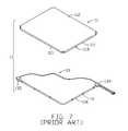
- FIG. 7is an exploded, isometric view of a conventional backlight module
- FIG. 8is an assembled view of the backlight module shown in FIG. 7
- the backlight module 1includes a light guide plate 11 and a light source 13 .
- the light guide plate 11includes a light output surface 112 , a bottom surface 113 opposite to the light output surface 112 , and two adjacent light incident surfaces 111 interconnecting the light output surface 112 and the bottom surface 113 .
- the light source 13includes an L-shaped lamp 131 and two electrode cases 133 .
- the electrode cases 133are respectively connected with two ends of the lamp 131 .
- the lamp 131is disposed adjacent to light incident surfaces 111 .
- a plurality of rubber rings 15is engaged around the lamp 131 , so as to prevent the lamp 131 from contacting the light incident surfaces 111 .
- the light source 11 and the light guide plate 13are generally not firmly fixed to each other.
- the LCDis liable to sustain vibration or shock, and the lamp 131 may be damaged or broken.
- the rubber rings 15have to be attached on the lamp 131 before the light source 11 is attached to the light guide plate 13 . This is an unduly laborious process, which increases the time needed for assembly and thus adds to manufacturing costs.
- a light guide plateincludes a light output surface, a bottom surface, two adjacent light incident surfaces and two side surfaces interconnecting the light output surface and the bottom surface, and two holding devices.
- the two holding devicesare respectively provided at diagonally opposite corners of the light guide plate, where the light incident surfaces are respectively adjacent the side surfaces, and the holding devices are for retaining electrode cases of a light source.
- a backlight moduleincludes a light source and the above-described light guide plate.
- the light sourceincludes a lamp and two electrode cases, the two electrode cases engage with opposite ends of the lamp.
- the light sourceis disposed adjacent to the light incident surfaces.
- the holding devicesare used for retaining the electrode cases.
- the backlight module employing the light guide plate disposed onto a frameis used in an LCD.
- the first and second sidewalls, the top wall, and the framecan prevent the electrode case from moving, so that the retaining space firmly fix the electrode case therein.
- the lampare not liable to shock, so the lamp can not be damaged.
- the backlight moduleeliminates the need for rubber rings. Thereby reducing the cost of the backlight module.
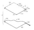
- FIG. 1is an exploded, isometric view of a backlight module according to a first embodiment of the present invention.
- FIG. 2is an enlarged view of a circled portion II of FIG. 1 .
- FIG. 3is an assembled view of the backlight module shown in FIG. 1 .
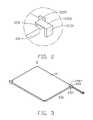
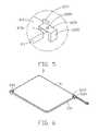
- FIG. 4is an exploded, isometric view of a backlight module according to a second embodiment of the present invention.
- FIG. 5is an enlarged view of a circled portion V of FIG. 4 .
- FIG. 6is an assembled view of the backlight module shown in FIG. 4 .
- FIG. 7is an exploded, isometric view of a conventional backlight module.
- FIG. 8is an assembled view of the backlight module shown in FIG. 7 .
- a backlight module 2includes a light guide plate 21 and a light source 23 .
- the light guide plate 21includes a light output surface 212 , a bottom surface 213 opposite to the light output surface 212 , and two adjacent light incident surfaces 211 and two adjacent side surfaces 214 interconnecting the light output surface 212 and the bottom surface 213 .
- a holding device 215is provided at each of two diagonally opposite corners of the light guide plate 21 where the light incident surfaces 211 adjoin the corresponding side surfaces 214 .
- the light source 23includes an L-shaped lamp 231 , and two electrode cases 233 connected with two opposite ends of the lamp 231 respectively.
- Each holding device 215includes a first sidewall 2151 , a second sidewall 2155 , and a top wall 2153 .
- the first sidewall 2151integrally extends upwardly from the light guide plate 21 to a level higher than the light output surface 212 .
- the first and second sidewalls 2151 , 2155are parallel to the corresponding light incident surface 211 , and the top wall 2153 horizontally interconnects the first and second sidewalls 2151 , 2155 .
- the first and second sidewalls 2151 , 2155 and the top wall 2153cooperatively define a first retaining space for fixing the corresponding electrode case 233 therein.
- the holding device 215further includes a third sidewall 2157 integrally extending upwardly from the light guide plate 21 to a same level as that of the first sidewall 2151 .
- the third sidewall 2157is perpendicular to and adjoins the first sidewall 2151 . That is, the third sidewall 2157 is parallel to and shares a common plane with the corresponding side surface 214 .
- the first and third sidewalls 2151 , 2157cooperatively define an inner holding corner of the holding device 215 .
- the inner holding corners of the holding devices 215 and the light output surface 212cooperatively define a second retaining space (not labeled) above the light guide plate 21 .
- Optical films of an associated LCDsuch as a prism film and a brightness enhancement film, can be held in the retaining space.
- the lamp 231 of the light source 23is disposed adjacent to the light incident surfaces 211 of the light guide plate 21 .
- the electrode cases 233 of the light source 23are fixed in the first retaining spaces of the holding devices 215 .
- the first and second sidewalls 2151 , 2155 of each holding device 215prevent the corresponding electrode case 233 from moving along directions perpendicular to the corresponding light incident surface 211 . In this position, a certain distance is maintained between the lamp 231 and each light incident surface 211 .
- the backlight module 2is disposed onto a frame of the associated LCD.
- the first and second sidewalls 2151 , 2155 , the top wall 2153 , and the framecooperatively prevent the corresponding electrode case 233 from moving. That is, the electrode case 233 is firmly fixed in the first retaining space. With the electrode cases 233 fixed thus, the lamp 231 is held securely in position. The lamp 231 is thus unlikely to sustain shock and resultant damage. Further, the backlight module 2 eliminates the need for rubber rings. Thereby, the cost of the backlight module 2 can be reduced.
- a backlight moduleincludes a light guide plate 31 and a light source 33 .
- the light guide plate 31includes a light output surface 312 , a bottom surface 313 opposite to the light output surface 312 , and two adjacent light incident surfaces 311 and two adjacent side surfaces 314 interconnecting the light output surface 312 and the bottom surface 313 .
- a holding device 315is provided at each of two diagonally opposite corners of the light guide plate 31 where the light incident surfaces 311 adjoin the corresponding side surfaces 314 .
- the light source 33includes an L-shaped lamp 331 , and two electrode cases 333 connected with two opposite ends of the lamp 331 respectively.
- Each holding device 315includes a first sidewall 3151 , a second sidewall 3155 , a top wall 3153 , a retaining space, a third sidewall 3157 , and an inner holding corner.
- the first sidewall 3151 , second sidewall 3155 , top wall 3153 , retaining space, third sidewall 3157 and inner holding cornerare similar to the first sidewall 2151 , second sidewall 2155 , top wall 2153 , first retaining space, third sidewall 2157 and inner holding corner of the corresponding holding device 215 of the backlight module 2 .
- the top wall 3153 of the holding device 315defines a hole 3159 therein.
- Each electrode case 333has an upper surface 335 .
- a post 337extends up from the upper surface 335 , for engaging in the hole 3159 of a corresponding holding device 315 .
- the lamp 331 of the light source 33is disposed adjacent to the light incident surfaces 311 of the light guide plate 31 .
- the electrode cases 333 of the light source 33are fixed in the retaining spaces of the holding devices 315 , with the posts 337 being engagingly received in the holes 3159 .
- the first and second sidewalls 3151 , 3155 of each holding device 315prevent the corresponding electrode case 333 from moving along directions perpendicular to the corresponding light incident surface 311 . In this position, a certain distance is maintained between the lamp 331 and each light incident surface 311 .
- the backlight module 3is disposed onto a frame of an associated LCD.
- the first and second sidewalls 3151 , 3155 , the top wall 3153 , and the framecooperatively prevent the corresponding electrode case 333 from moving. That is, the electrode case 333 is firmly fixed in the retaining space. With the electrode cases 333 fixed thus, the lamp 331 is held securely in position. The lamp 331 is thus unlikely to sustain shock and resultant damage. Further, the backlight module 3 eliminates the need for rubber rings. Thereby, the cost of the backlight module 3 can be reduced.
Landscapes
- Physics & Mathematics (AREA)
- General Physics & Mathematics (AREA)
- Optics & Photonics (AREA)
- Planar Illumination Modules (AREA)
Abstract
Description
Claims (15)
Applications Claiming Priority (2)
| Application Number | Priority Date | Filing Date | Title |
|---|---|---|---|
| TW93220813 | 2004-12-24 | ||
| TW093220813UTWM270373U (en) | 2004-12-24 | 2004-12-24 | Light guide plate and backlight module |
Publications (2)
| Publication Number | Publication Date |
|---|---|
| US20060139961A1 US20060139961A1 (en) | 2006-06-29 |
| US7419293B2true US7419293B2 (en) | 2008-09-02 |
Family
ID=36611275
Family Applications (1)
| Application Number | Title | Priority Date | Filing Date |
|---|---|---|---|
| US11/317,115Expired - Fee RelatedUS7419293B2 (en) | 2004-12-24 | 2005-12-23 | Light guide plate and backlight module using the same |
Country Status (2)
| Country | Link |
|---|---|
| US (1) | US7419293B2 (en) |
| TW (1) | TWM270373U (en) |
Cited By (2)
| Publication number | Priority date | Publication date | Assignee | Title |
|---|---|---|---|---|
| US20080123369A1 (en)* | 2006-11-27 | 2008-05-29 | Au Optronics Corporation | Backlight Module and an Optical Slice Unit Support Device Thereof |
| US20090323371A1 (en)* | 2008-06-27 | 2009-12-31 | Ho-Han Ryu | Light source apparatus, method of manufacturing the light source apparatus and backlight assembly having the same |
Families Citing this family (5)
| Publication number | Priority date | Publication date | Assignee | Title |
|---|---|---|---|---|
| JP2006155929A (en)* | 2004-11-25 | 2006-06-15 | Toshiba Matsushita Display Technology Co Ltd | Surface light source apparatus and liquid crystal display |
| JP4459109B2 (en)* | 2005-05-13 | 2010-04-28 | 東芝モバイルディスプレイ株式会社 | Surface light source device and liquid crystal display device provided with the surface light source device |
| TWI420435B (en)* | 2008-12-12 | 2013-12-21 | Innolux Corp | Flat display apparatus and frame unit thereof |
| TWI393960B (en)* | 2009-11-06 | 2013-04-21 | Au Optronics Corp | Frame, metal frame, backlight module, and lcd thereof |
| CN112051638A (en)* | 2020-08-31 | 2020-12-08 | 惠州市隆利科技发展有限公司 | Backlight module and its anti-detachment pre-assembly |
Citations (12)
| Publication number | Priority date | Publication date | Assignee | Title |
|---|---|---|---|---|
| US5619351A (en) | 1992-07-13 | 1997-04-08 | Seiko Epson Corporation | Surface-type illumination device and liquid crystal display |
| US5990989A (en)* | 1995-03-31 | 1999-11-23 | Seiko Epson Corporation | Noise-shield sheet and liquid crystal display device using the same |
| US6231202B1 (en)* | 1998-08-20 | 2001-05-15 | Matsushita Electric Industrial Co., Ltd. | Lighting unit and liquid crystal display device using the same |
| US6343868B1 (en)* | 1999-09-09 | 2002-02-05 | Advanced Display Inc. | Sheet-like light source device |
| US6545732B2 (en)* | 2000-01-27 | 2003-04-08 | Advanced Display Inc. | Backlight assembly for liquid crystal display device |
| US20040090766A1 (en)* | 2002-11-13 | 2004-05-13 | Mi-Chien Chen | Surface light source device |
| US6811276B2 (en)* | 2002-04-03 | 2004-11-02 | Lg. Philips Lcd Co., Ltd. | Backlight device |
| US6834974B2 (en)* | 2002-06-25 | 2004-12-28 | Samsung Electronics Co., Ltd. | Lamp assembly, backlight assembly and liquid crystal display apparatus having the same |
| US6839100B1 (en)* | 1999-01-26 | 2005-01-04 | Hitachi, Ltd. | Liquid crystal display device |
| US6910784B2 (en)* | 2002-03-25 | 2005-06-28 | Advanced Display Inc. | Panel light source device and fabrication process for the same |
| US20050180171A1 (en)* | 2004-02-18 | 2005-08-18 | Hsin-Tao Huang | Back light module of liquid crystal display device |
| US7014350B2 (en)* | 2002-09-18 | 2006-03-21 | Matsushita Electric Industrial Co., Ltd. | Illumination unit and liquid crystal display comprising it |
- 2004
- 2004-12-24TWTW093220813Upatent/TWM270373U/ennot_activeIP Right Cessation
- 2005
- 2005-12-23USUS11/317,115patent/US7419293B2/ennot_activeExpired - Fee Related
Patent Citations (14)
| Publication number | Priority date | Publication date | Assignee | Title |
|---|---|---|---|---|
| US5619351A (en) | 1992-07-13 | 1997-04-08 | Seiko Epson Corporation | Surface-type illumination device and liquid crystal display |
| US5990989A (en)* | 1995-03-31 | 1999-11-23 | Seiko Epson Corporation | Noise-shield sheet and liquid crystal display device using the same |
| US6231202B1 (en)* | 1998-08-20 | 2001-05-15 | Matsushita Electric Industrial Co., Ltd. | Lighting unit and liquid crystal display device using the same |
| US6839100B1 (en)* | 1999-01-26 | 2005-01-04 | Hitachi, Ltd. | Liquid crystal display device |
| US6343868B1 (en)* | 1999-09-09 | 2002-02-05 | Advanced Display Inc. | Sheet-like light source device |
| US6545732B2 (en)* | 2000-01-27 | 2003-04-08 | Advanced Display Inc. | Backlight assembly for liquid crystal display device |
| US6910784B2 (en)* | 2002-03-25 | 2005-06-28 | Advanced Display Inc. | Panel light source device and fabrication process for the same |
| US6811276B2 (en)* | 2002-04-03 | 2004-11-02 | Lg. Philips Lcd Co., Ltd. | Backlight device |
| US6834974B2 (en)* | 2002-06-25 | 2004-12-28 | Samsung Electronics Co., Ltd. | Lamp assembly, backlight assembly and liquid crystal display apparatus having the same |
| US7014350B2 (en)* | 2002-09-18 | 2006-03-21 | Matsushita Electric Industrial Co., Ltd. | Illumination unit and liquid crystal display comprising it |
| US20040090766A1 (en)* | 2002-11-13 | 2004-05-13 | Mi-Chien Chen | Surface light source device |
| US6966686B2 (en)* | 2002-11-13 | 2005-11-22 | Hon Hai Precision Ind. Co., Ltd. | Surface light source device |
| US20050180171A1 (en)* | 2004-02-18 | 2005-08-18 | Hsin-Tao Huang | Back light module of liquid crystal display device |
| US7207707B2 (en)* | 2004-02-18 | 2007-04-24 | Au Optronics Corporation | Back light module of liquid crystal display device |
Cited By (4)
| Publication number | Priority date | Publication date | Assignee | Title |
|---|---|---|---|---|
| US20080123369A1 (en)* | 2006-11-27 | 2008-05-29 | Au Optronics Corporation | Backlight Module and an Optical Slice Unit Support Device Thereof |
| US7677785B2 (en)* | 2006-11-27 | 2010-03-16 | Au Optronics Corporation | Backlight module and an optical slice unit support device thereof |
| US20090323371A1 (en)* | 2008-06-27 | 2009-12-31 | Ho-Han Ryu | Light source apparatus, method of manufacturing the light source apparatus and backlight assembly having the same |
| US8434926B2 (en)* | 2008-06-27 | 2013-05-07 | Samsung Display Co., Ltd. | Light source apparatus, method of manufacturing the light source apparatus and backlight assembly having the same |
Also Published As
| Publication number | Publication date |
|---|---|
| TWM270373U (en) | 2005-07-11 |
| US20060139961A1 (en) | 2006-06-29 |
Similar Documents
| Publication | Publication Date | Title |
|---|---|---|
| KR101385231B1 (en) | Flat panel display | |
| US7237941B2 (en) | Backlight module with urged light guide plate and liquid crystal display having same | |
| US7891859B2 (en) | Frame and backlight module using the same | |
| US20070121346A1 (en) | Backlight assembly with optical film having positioning flange | |
| US7656470B2 (en) | Backlight module with light guide plate having first ear (tab) with structure for holding second ear of optical film localized (locked) by the first ear and LCD for same | |
| CN102024390A (en) | Image display device | |
| KR20110081671A (en) | Back light unit and liquid crystal display device having the same | |
| KR20080107633A (en) | Liquid crystal display | |
| US7241041B2 (en) | Backlight module | |
| KR20150135817A (en) | Backlight unit | |
| KR20090100117A (en) | Backlight unit and liquid crystal display including the same | |
| US20050185424A1 (en) | Backlight module | |
| KR20120084072A (en) | Display device | |
| US20080094789A1 (en) | Flat panel display | |
| US8031291B2 (en) | Liquid crystal display and tablet computer having a chassis fastening member that receives a printed circuit board | |
| US20060203142A1 (en) | Liquid crystal display device | |
| US7575361B2 (en) | Backlight module with buffering protrusions and liquid crystal display with same | |
| US7419293B2 (en) | Light guide plate and backlight module using the same | |
| KR101929378B1 (en) | Liquid crystal display device | |
| US7281837B2 (en) | Transflective frame and backlight module using the same | |
| KR20080071407A (en) | Backlight unit and liquid crystal display including the same | |
| KR20080067846A (en) | Liquid crystal display | |
| US20060187376A1 (en) | Backlight module and liquid crystal display module | |
| US20070047255A1 (en) | Backlight module and liquid crystal display module | |
| KR100983500B1 (en) | Flat panel display |
Legal Events
| Date | Code | Title | Description |
|---|---|---|---|
| AS | Assignment | Owner name:INNOLUX DISPLAY CORP., TAIWAN Free format text:ASSIGNMENT OF ASSIGNORS INTEREST;ASSIGNORS:YU, CHIH-CHIA;CHANG, CHENG-FANG;REEL/FRAME:017416/0958 Effective date:20051219 | |
| STCF | Information on status: patent grant | Free format text:PATENTED CASE | |
| FPAY | Fee payment | Year of fee payment:4 | |
| AS | Assignment | Owner name:CHIMEI INNOLUX CORPORATION, TAIWAN Free format text:CHANGE OF NAME;ASSIGNOR:INNOLUX DISPLAY CORP.;REEL/FRAME:032672/0685 Effective date:20100330 Owner name:INNOLUX CORPORATION, TAIWAN Free format text:CHANGE OF NAME;ASSIGNOR:CHIMEI INNOLUX CORPORATION;REEL/FRAME:032672/0746 Effective date:20121219 | |
| FPAY | Fee payment | Year of fee payment:8 | |
| FEPP | Fee payment procedure | Free format text:MAINTENANCE FEE REMINDER MAILED (ORIGINAL EVENT CODE: REM.); ENTITY STATUS OF PATENT OWNER: LARGE ENTITY | |
| LAPS | Lapse for failure to pay maintenance fees | Free format text:PATENT EXPIRED FOR FAILURE TO PAY MAINTENANCE FEES (ORIGINAL EVENT CODE: EXP.); ENTITY STATUS OF PATENT OWNER: LARGE ENTITY | |
| STCH | Information on status: patent discontinuation | Free format text:PATENT EXPIRED DUE TO NONPAYMENT OF MAINTENANCE FEES UNDER 37 CFR 1.362 | |
| FP | Expired due to failure to pay maintenance fee | Effective date:20200902 |