US7419208B2 - Carrier for front end module of vehicle - Google Patents
Carrier for front end module of vehicleDownload PDFInfo
- Publication number
- US7419208B2 US7419208B2US11/700,306US70030607AUS7419208B2US 7419208 B2US7419208 B2US 7419208B2US 70030607 AUS70030607 AUS 70030607AUS 7419208 B2US7419208 B2US 7419208B2
- Authority
- US
- United States
- Prior art keywords
- side panels
- panel
- carrier
- upper panel
- end portion
- Prior art date
- Legal status (The legal status is an assumption and is not a legal conclusion. Google has not performed a legal analysis and makes no representation as to the accuracy of the status listed.)
- Active
Links
- 238000001816coolingMethods0.000claimsabstractdescription23
- 230000008878couplingEffects0.000claimsabstractdescription22
- 238000010168coupling processMethods0.000claimsabstractdescription22
- 238000005859coupling reactionMethods0.000claimsabstractdescription22
- 230000003014reinforcing effectEffects0.000claimsabstractdescription18
- 229920003002synthetic resinPolymers0.000claimsdescription15
- 239000000057synthetic resinSubstances0.000claimsdescription15
- 239000002184metalSubstances0.000claimsdescription12
- 238000002347injectionMethods0.000claimsdescription10
- 239000007924injectionSubstances0.000claimsdescription10
- 238000001746injection mouldingMethods0.000claimsdescription10
- 230000000994depressogenic effectEffects0.000claimsdescription3
- 238000000034methodMethods0.000description2
- 238000010276constructionMethods0.000description1
- 239000012050conventional carrierSubstances0.000description1
- 239000002826coolantSubstances0.000description1
- 239000000498cooling waterSubstances0.000description1
- 238000012423maintenanceMethods0.000description1
- 238000004519manufacturing processMethods0.000description1
- 238000012986modificationMethods0.000description1
- 230000004048modificationEffects0.000description1
- 238000007711solidificationMethods0.000description1
- 230000008023solidificationEffects0.000description1
Images


Classifications
- B—PERFORMING OPERATIONS; TRANSPORTING
- B62—LAND VEHICLES FOR TRAVELLING OTHERWISE THAN ON RAILS
- B62D—MOTOR VEHICLES; TRAILERS
- B62D29/00—Superstructures, understructures, or sub-units thereof, characterised by the material thereof
- B62D29/001—Superstructures, understructures, or sub-units thereof, characterised by the material thereof characterised by combining metal and synthetic material
- B—PERFORMING OPERATIONS; TRANSPORTING
- B62—LAND VEHICLES FOR TRAVELLING OTHERWISE THAN ON RAILS
- B62D—MOTOR VEHICLES; TRAILERS
- B62D25/00—Superstructure or monocoque structure sub-units; Parts or details thereof not otherwise provided for
- B62D25/08—Front or rear portions
- B62D25/082—Engine compartments
- B62D25/084—Radiator supports
- B—PERFORMING OPERATIONS; TRANSPORTING
- B62—LAND VEHICLES FOR TRAVELLING OTHERWISE THAN ON RAILS
- B62D—MOTOR VEHICLES; TRAILERS
- B62D29/00—Superstructures, understructures, or sub-units thereof, characterised by the material thereof
- B62D29/001—Superstructures, understructures, or sub-units thereof, characterised by the material thereof characterised by combining metal and synthetic material
- B62D29/004—Superstructures, understructures, or sub-units thereof, characterised by the material thereof characterised by combining metal and synthetic material the metal being over-moulded by the synthetic material, e.g. in a mould
- B—PERFORMING OPERATIONS; TRANSPORTING
- B62—LAND VEHICLES FOR TRAVELLING OTHERWISE THAN ON RAILS
- B62D—MOTOR VEHICLES; TRAILERS
- B62D29/00—Superstructures, understructures, or sub-units thereof, characterised by the material thereof
- B62D29/001—Superstructures, understructures, or sub-units thereof, characterised by the material thereof characterised by combining metal and synthetic material
- B62D29/005—Superstructures, understructures, or sub-units thereof, characterised by the material thereof characterised by combining metal and synthetic material preformed metal and synthetic material elements being joined together, e.g. by adhesives
Definitions
- the present inventionrelates to a carrier for a front end module of a vehicle, and more particularly, to a carrier for a front end module of a vehicle which is capable of removably coupling an upper central panel.
- a cooling modulesuch as a radiator or a condenser for heat exchanging cooling water or coolant of an air conditioner is installed in a front area of a vehicle body; a front end module is employed to parts such as cooling modules, head lamps, a bumper and so on to reduce man hour and number of parts.
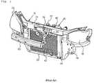
- the carrier for a front end moduleincludes, as shown in FIG.
- a carrier 10a carrier 10 , a condenser 42 mounted on the center of the carrier, radiator 44 and a cooling module 40 , having a fan shroud assembly 46 , head lamps 50 installed at both sides of an upper portion of the carrier 10 , and a bumper (not shown) installed by a bumper beam 60 at a front side of a lower end portion of the carrier 10 .
- the carrier 10is provided with an upper panel 20 , a lower panel 22 arranged parallel to the upper panel 20 and two side panels 24 for connecting both sides of central portions of the upper and lower panels respectively so as to form a generally rectangular part for mounting the cooling module at a central portion of the carrier 10 .
- a pair of head lamp mounting part 32is formed for mounting the head lamps 50 respectively across from both end portions of the upper panel 20 to the both side panels 24 and bumper mounting parts 34 are formed for mounting the bumper beam 60 at a portion of each side panel 24 which is located at a lower side of the head lamp mounting part 32 , respectively.
- a center stay 26 for connecting central portions of the upper and lower panels 20 and 22may be applied for the purpose of reinforcing the carrier 10 constructed as above mentioned while installing a hood latch assembly 70 .
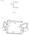
- hybrid carrierconstructed with metal and synthetic resins together, which can be relatively easily manufactured in an integral structure as shown in FIG. 2 by arranging into a mold an upper metal member 20 a for reinforcing an upper end of the hybrid carrier, a lower metal member 22 a for reinforcing a lower end of the hybrid carrier and two side metal members 34 a for reinforcing both sides of the hybrid carrier, each shown in. FIG. 3 , and performing insert injection molding with synthetic resins.
- the upper metal member 20 aAs shown in FIG. 4 , generally has a structure of a rearwardly opened channel type, there is a problem that rigidity is insufficient for supporting the cooling module 40 .
- poor appearancemay be generated as appearance or size of the molded product does not fit due to a complicated shape and the mold should be modified if the appearance or the size of the molded product does not fit.
- the hybrid carrieris formed in an integral structure by the insert injection molding and thus it is inconvenient to construct or maintain the cooling module 40 mounted in the cooling module mounting part 30 since space of an engine room is small.
- a carrier for a front end module of a vehicleincludes two side panels, each formed with a bumper mounting part at an outside thereof; a lower panel arranged across lower ends of the two side panels; two head lamp mounting parts formed outwardly at both sides of an upper end portion of the side panels; and an upper panel formed in a channel type structure with a downwardly opened U-shape so that both ends thereof are inserted in and removably coupled to a coupling part formed at an upper end of the side panels, and forming a cooling module mounting part together with the side panels and the lower panel.
- the side panels and the lower panelare formed of metal and then are insert injection molded with synthetic resins so as to be connected to each other, and the head lamp mounting part is formed of synthetic resins and is integrated in a hybrid structure to the side panels by the insert injection molding.
- the upper panelis preferably formed of metal.
- a reinforcing panel with a structure of downwardly opened channel typeis installed along a lower end portion of a downwardly opened portion of the upper panel, thereby reinforcing rigidity of the upper panel.
- a hood latch assemblyis preferably coupled to a central portion of a front side or rear side of the upper panel.
- the carrier for a front end module of a vehicleis preferably further provided with a first through hole formed at an end portion of the upper panel which is coupled to the coupling part of the side panel, a second through hole formed at a position of the coupling part corresponding to the first through hole, and a fastening means passing through the first and second through holes together for coupling the side panel and the upper panel.
- the coupling partis filled with synthetic resins and is formed to have higher strength than that of the other portion of the side panel.
- the coupling partis preferably formed with a depressed portion for preventing deformation when injection molding of the synthetic resins.
- FIG. 1is a perspective view illustrating an example of a front end module of a conventional vehicle.
- FIG. 2is a perspective view illustrating a prior hybrid carrier applied to the front end module of the vehicle in FIG. 1 .
- FIG. 3is an exploded perspective view partially illustrating the prior hybrid carrier.
- FIG. 4is a sectional view illustrating an upper metal member which constructs the prior hybrid carrier.
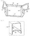
- FIG. 5is an exploded perspective view illustrating a carrier for a front end module of a vehicle according to the present invention.
- FIG. 6is an assembled perspective view illustrating the carrier for a front end module of a vehicle according to the present invention.
- FIG. 7is a partial perspective view illustrating an inner structure of an upper panel which constructs the carrier for a front end module of a vehicle according to the present invention.
- FIG. 8is a partial perspective view illustrating an assembled structure of the upper panel which constructs the carrier for a front end module of a vehicle according to the present invention.
- FIG. 9is a partial perspective view illustrating another assembled structure of the upper panel which constructs the carrier for a front end module of a vehicle according to the present invention.
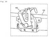
- FIG. 10is a partial perspective view illustrating a state that a hood latch assembly is coupled to the upper panel which constructs the carrier for a front end module of a vehicle according to the present invention.
- FIG. 5 and FIG. 6show a carrier for a front end module of a vehicle according to the present invention.
- the carrier according to the present inventionincludes two side panels 100 , a lower panel 110 , two head lamp mounting parts 120 and an upper panel 130 .
- the side panel 100is provided with a bumper mounting part 102 for mounting a bumper beam 60 (see FIG. 1 ) at an outside thereof, in which a pair of the bumper mounting parts 102 are arranged in parallel with each other in a predetermined space.
- the lower panel 110is arranged across lower ends of the side panels 100 .
- the side panels 100 and the lower panel 110are made of metal and insert injection molded with synthetic resins so as to be connected to each other.
- head lamp mounting parts 120 for mounting head lamp 50 (see FIG. 1 ) outwardly at both sides of an upper end portions of the side panels 100are made of synthetic resin by the insert injection molding, thereby capable of being connected to the side panels 100 .
- the side panels 100 , the lower panel 110 and the head lamp mounting parts 120are integrated in a hybrid structure.
- both ends of the upper panel 130are removably coupled to upper ends of the side panels 100 , and forms a cooling module mounting part 150 for mounting a cooling module 40 (see FIG. 1 ) together with the side panels 100 and the lower panel 110 .
- first through holes 131are formed at end portions of the upper panel which are coupled to coupling parts 101 of both side panels 100 and second through holes 102 are formed at positions of the coupling parts 101 corresponding to the first through holes 131 , and the upper panel 130 and the side panels 100 are firmly fastened by a fastening means 142 such as a bolt and a nut.
- a fastening means 142such as a bolt and a nut.
- the upper panel 130may be a separated type while increasing coupling strength between the upper panel and side panels.
- two of the fastening means 142are preferably provided at both sides respectively.
- the upper panel 130has a structure of a downwardly opened channel type. Therefore, as shown in FIG. 8 , an upper end of the side panels 100 (specifically, an upper end of a portion where the side panel 100 and the head lamp mounting part 120 are coupled) can be inserted into both ends of the upper panel 130 , which are removably coupled by fastening means 142 such as a bolt and a nut.
- fastening means 142such as a bolt and a nut.
- the coupling part 101is filled with synthetic resins. Since, if full of synthetic resins when injection molded, difference in temperature is excessively generated between a central portion and a periphery and thus torsion is generated in process of solidification, which may lead to deformation of the carrier, a depressed part 122 is preferably formed so as to prevent such deformation.
- a reinforcing panel 140 having a channel type structure which is opened downwardly along a lower end thereofis installed in a portion of the upper panel 130 which is opened downwardly thereby reinforcing rigidity of the upper panel 130 .
- such structure for reinforcing the rigiditymay be diversely varied and which should be included in a scope of the present invention.
- a hood latch assembly 160is coupled to a central portion of a front side of the upper panel 130 . Further, though it is not shown, the hood latch assembly 160 may be coupled to a central portion of a rear side of the upper panel 130 , which should also be included in the scope of the present invention.
- side panels 100 and lower panel 110are pre-produced with metal, and they are inserted into a injection mold, and then the side panels 100 and lower panel 110 are integrated in the hybrid structure by injection molded product of synthetic resins which formed by injection molding, and further the head lamp mounting parts 120 are integrated to the side panels 100 simultaneously through the insert injection molding.
- the pre-produced upper panel 130is assembled by the fastening means 142 to the insert injection molded product which is integrated in the hybrid structure as above mentioned.
- the hood latch assembly 160is mounted in the upper panel 130 either before or after the upper panel 130 is assembled to the insert injection molded product of integrated hybrid structure.
- a fastening means for mounting the cooling module in the upper panel 130is separated, then the fastening means 142 each fastened at both sides of the upper panel 130 is removed so as to separate the upper panel 130 and then it is possible to maintain the troubled portion of the cooling module, whereby the cooling module can be easily maintained in a small space of an engine room and maintenance of other parts mounted in the engine room also can be easily performed.
- rigidity of the carrier of the present inventioncan be varied or a matter varied according to vehicles can be easily reflected by modifying and varying the upper panel 130 alone.
- the carrier for a front end module of a vehicle constructed as described abovesince the upper panel 130 is constructed to be removably mountable, modification of injection mold for insert injection molding, particularly in the hybrid structure, or occurrence of poor appearance or poor dimensions can be prevented as it is possible to compensate correctly an appearance or dimensions of integrated other structures while assembling the upper panel 130 if an appearance or dimensions of the integrated other structures do not match.
- the upper panel 130is constructed to be removably mountable, maintainability can be improved as a troubled part such as the cooling module can be maintained after the upper panel 130 is removed.
- maintainability or convenience in vehicle designcan be further improved as a matter varied according to vehicles can be easily reflected by modifying and varying the upper panel 130 alone.
- rigidity of the carriercan be improved and a rigid structure can be improved only by modifying or varying the upper panel 130 or the reinforcing panel 140 .
- hood latch assembly 160 or other partscan be mounted the upper panel 130 having improved rigidity, it is possible to prevent breathablity of the cooling module from being obstructed by a conventional center stay for mounting the hood latch assembly 160 and to reduce a number of parts.
Landscapes
- Engineering & Computer Science (AREA)
- Chemical & Material Sciences (AREA)
- Combustion & Propulsion (AREA)
- Transportation (AREA)
- Mechanical Engineering (AREA)
- Architecture (AREA)
- Structural Engineering (AREA)
- Body Structure For Vehicles (AREA)
Abstract
Description
Claims (6)
Applications Claiming Priority (4)
| Application Number | Priority Date | Filing Date | Title |
|---|---|---|---|
| KR20060010537 | 2006-02-03 | ||
| KR10-2006-0010537 | 2006-02-03 | ||
| KR1020070004963AKR101251881B1 (en) | 2006-02-03 | 2007-01-16 | Carrier for front end module of vehicle |
| KR10-2007-0004963 | 2007-01-16 |
Publications (2)
| Publication Number | Publication Date |
|---|---|
| US20070182211A1 US20070182211A1 (en) | 2007-08-09 |
| US7419208B2true US7419208B2 (en) | 2008-09-02 |
Family
ID=38333312
Family Applications (1)
| Application Number | Title | Priority Date | Filing Date |
|---|---|---|---|
| US11/700,306ActiveUS7419208B2 (en) | 2006-02-03 | 2007-01-31 | Carrier for front end module of vehicle |
Country Status (1)
| Country | Link |
|---|---|
| US (1) | US7419208B2 (en) |
Cited By (13)
| Publication number | Priority date | Publication date | Assignee | Title |
|---|---|---|---|---|
| US20090008818A1 (en)* | 2005-05-12 | 2009-01-08 | Compagnie Plastic Omnium | Method for Fitting a Bumper Shell Around Light Units Stay for a Bumper Shell and Headlight Unit for Motor Vehicles |
| US20090218834A1 (en)* | 2008-02-29 | 2009-09-03 | Nissan Technical Center North America, Inc. | Vehicle bumper fascia retainer |
| US20100026049A1 (en)* | 2006-09-25 | 2010-02-04 | Faurecia Bloc Avant | Motor vehicle front-end panel, series of front-end panels and assembly method |
| US20100213742A1 (en)* | 2009-02-20 | 2010-08-26 | Dr. Ing. H.C. F. Porsche Aktiengesellschaft | Front end module for a motor vehicle |
| US20110037292A1 (en)* | 2009-08-14 | 2011-02-17 | Faurecia Interior Systems | Automotive Front Support Beam, Front Carrier, And A Method Of Assembly |
| US20110210574A1 (en)* | 2010-02-26 | 2011-09-01 | Suzuki Motor Corporation | Joining mechanism |
| US8857901B2 (en)* | 2012-12-24 | 2014-10-14 | Kia Motors Corporation | Front end module for vehicle |
| US20140305725A1 (en)* | 2013-04-12 | 2014-10-16 | GM Global Technology Operations LLC | Collapsible hood bumper with reset feature |
| US20170233011A1 (en)* | 2016-02-12 | 2017-08-17 | Valeo Front-End Modules Inc. | Front end module for a vehicle |
| US20180118441A1 (en)* | 2016-11-02 | 2018-05-03 | Joseph Wycech | Biodegradable packaging component |
| US9987995B2 (en) | 2015-01-21 | 2018-06-05 | Ranger Design | Ladder storing and releasing assembly |
| US10189507B2 (en) | 2015-01-20 | 2019-01-29 | Honda Motor Co., Ltd. | Vehicle body front structure |
| US20240300585A1 (en)* | 2021-01-28 | 2024-09-12 | Psa Automobiles Sa | Front structure of a motor vehicle comprising an upper cross-member and vehicle comprising such a front structure |
Families Citing this family (14)
| Publication number | Priority date | Publication date | Assignee | Title |
|---|---|---|---|---|
| FR2873649B1 (en)* | 2004-08-02 | 2006-11-24 | Faurecia Bloc Avant | FRONT BLOCK ASSEMBLY OF MOTOR VEHICLE |
| FR2888197B1 (en)* | 2005-07-08 | 2007-10-12 | Faurecia Bloc Avant | FRONT BLOCK ASSEMBLY OF A CORRESPONDING MOTOR VEHICLE. |
| FR2919566B1 (en)* | 2007-08-03 | 2010-04-30 | Faurecia Bloc Avant | FRONT PANEL OF MOTOR VEHICLE WITH TRAVERSE AT THE LEVEL OF THE MAIN LONGERONS |
| US8220576B2 (en)* | 2007-10-01 | 2012-07-17 | Mazda Motor Corporation | Front end structure for automobile |
| FR2932759B1 (en)* | 2008-06-20 | 2011-03-11 | Renault Sas | ARRANGEMENT OF A TECHNICAL FRONT PANEL COMPRISING REINFORCING MEANS. |
| DE102008048039A1 (en)* | 2008-09-19 | 2010-03-25 | Volkswagen Ag | Front end on a vehicle, in particular motor vehicle |
| DE102009043363A1 (en)* | 2009-09-29 | 2011-04-07 | Hbpo Gmbh | front end module |
| ES2551287T3 (en)* | 2012-03-08 | 2015-11-17 | Faurecia Exteriors Gmbh | Injection molded structural component with a hollow structural section |
| CN105460080B (en)* | 2014-09-25 | 2017-11-28 | 翰昂系统株式会社 | Vehicle carrier rack |
| FR3030432B1 (en)* | 2014-12-18 | 2018-04-27 | Renault S.A.S | TECHNICAL FRONT FRONT STRUCTURE OF PARTIALLY DEMONABLE MOTOR VEHICLE. |
| FR3031952B1 (en)* | 2015-01-27 | 2018-09-14 | Valeo Systemes Thermiques | FRONT PANEL MODULE FOR MOTOR VEHICLE |
| KR102687163B1 (en)* | 2019-07-24 | 2024-07-19 | 현대자동차주식회사 | Front body structure of vehicle |
| JP7480514B2 (en)* | 2020-02-10 | 2024-05-10 | 三菱自動車工業株式会社 | Vehicle front structure |
| KR20220099240A (en)* | 2021-01-06 | 2022-07-13 | 현대자동차주식회사 | Radiator support assembly |
Citations (13)
| Publication number | Priority date | Publication date | Assignee | Title |
|---|---|---|---|---|
| US6189958B1 (en)* | 1998-09-30 | 2001-02-20 | Valeo Thermique Moteur | Reinforced metal/plastic composite front panel for a motor vehicle |
| US6196624B1 (en)* | 1998-12-21 | 2001-03-06 | Ecia Industrie | Cross-beam and disposition thereof in an automobile vehicle |
| JP2001180520A (en) | 1999-12-24 | 2001-07-03 | Stanley Electric Co Ltd | Front-end module |
| US6375252B1 (en)* | 1999-11-15 | 2002-04-23 | Compagnie Plastic Omnium | Motor vehicle functional front end referenced to the wing of a vehicle |
| US6412855B1 (en)* | 1998-09-30 | 2002-07-02 | Valeo Thermique Moteur | Overmoulded reinforced metal/plastic composite front panel for motor vehicle |
| US6450276B1 (en)* | 1999-07-30 | 2002-09-17 | Valeo Inc. | Modular vehicle front end |
| US6517146B1 (en)* | 1999-11-15 | 2003-02-11 | Compagnie Plastic Omnium | Attachment of front quadrant to crossmember |
| US6619419B1 (en)* | 1999-11-15 | 2003-09-16 | Renault S.A.S. | Motor vehicle functional front end, without radiator |
| US6672652B2 (en)* | 2001-06-15 | 2004-01-06 | Fuji Jukogyo Kabushiki Kaisha | Front end structure of a vehicle |
| US6729424B2 (en)* | 2000-11-29 | 2004-05-04 | Calsonic Kansei Corporation | Radiator core support structure of motor vehicle |
| US20050253419A1 (en)* | 2004-05-17 | 2005-11-17 | Hyundai Mobis Co., Ltd. | Structure for mounting horizontal hood latch to upper panel of front-end module of automobile |
| US20050275250A1 (en)* | 2004-06-09 | 2005-12-15 | Calsonic Kansei Corporation | Attachment structure of head lamp and bumper fascia side portion |
| US20050275227A1 (en)* | 2004-06-11 | 2005-12-15 | Hyundai Mobis Co., Ltd. | Bumper-cover mounting structure of carrier |
- 2007
- 2007-01-31USUS11/700,306patent/US7419208B2/enactiveActive
Patent Citations (13)
| Publication number | Priority date | Publication date | Assignee | Title |
|---|---|---|---|---|
| US6412855B1 (en)* | 1998-09-30 | 2002-07-02 | Valeo Thermique Moteur | Overmoulded reinforced metal/plastic composite front panel for motor vehicle |
| US6189958B1 (en)* | 1998-09-30 | 2001-02-20 | Valeo Thermique Moteur | Reinforced metal/plastic composite front panel for a motor vehicle |
| US6196624B1 (en)* | 1998-12-21 | 2001-03-06 | Ecia Industrie | Cross-beam and disposition thereof in an automobile vehicle |
| US6450276B1 (en)* | 1999-07-30 | 2002-09-17 | Valeo Inc. | Modular vehicle front end |
| US6517146B1 (en)* | 1999-11-15 | 2003-02-11 | Compagnie Plastic Omnium | Attachment of front quadrant to crossmember |
| US6375252B1 (en)* | 1999-11-15 | 2002-04-23 | Compagnie Plastic Omnium | Motor vehicle functional front end referenced to the wing of a vehicle |
| US6619419B1 (en)* | 1999-11-15 | 2003-09-16 | Renault S.A.S. | Motor vehicle functional front end, without radiator |
| JP2001180520A (en) | 1999-12-24 | 2001-07-03 | Stanley Electric Co Ltd | Front-end module |
| US6729424B2 (en)* | 2000-11-29 | 2004-05-04 | Calsonic Kansei Corporation | Radiator core support structure of motor vehicle |
| US6672652B2 (en)* | 2001-06-15 | 2004-01-06 | Fuji Jukogyo Kabushiki Kaisha | Front end structure of a vehicle |
| US20050253419A1 (en)* | 2004-05-17 | 2005-11-17 | Hyundai Mobis Co., Ltd. | Structure for mounting horizontal hood latch to upper panel of front-end module of automobile |
| US20050275250A1 (en)* | 2004-06-09 | 2005-12-15 | Calsonic Kansei Corporation | Attachment structure of head lamp and bumper fascia side portion |
| US20050275227A1 (en)* | 2004-06-11 | 2005-12-15 | Hyundai Mobis Co., Ltd. | Bumper-cover mounting structure of carrier |
Cited By (21)
| Publication number | Priority date | Publication date | Assignee | Title |
|---|---|---|---|---|
| US20090008818A1 (en)* | 2005-05-12 | 2009-01-08 | Compagnie Plastic Omnium | Method for Fitting a Bumper Shell Around Light Units Stay for a Bumper Shell and Headlight Unit for Motor Vehicles |
| US7914070B2 (en)* | 2005-05-12 | 2011-03-29 | Compagnie Plastic Omnium | Method for fitting a bumper shell around light units stay for a bumper shell and headlight unit for motor vehicles |
| US20100026049A1 (en)* | 2006-09-25 | 2010-02-04 | Faurecia Bloc Avant | Motor vehicle front-end panel, series of front-end panels and assembly method |
| US7909391B2 (en)* | 2006-09-25 | 2011-03-22 | Faurecia Bloc Avant | Motor vehicle front-end panel, series of front-end panels and assembly method |
| US20090218834A1 (en)* | 2008-02-29 | 2009-09-03 | Nissan Technical Center North America, Inc. | Vehicle bumper fascia retainer |
| US7644966B2 (en)* | 2008-02-29 | 2010-01-12 | Nissan Technical Center North America, Inc. | Vehicle bumper fascia retainer |
| US8191959B2 (en)* | 2009-02-20 | 2012-06-05 | Dr. Ing. H.C. F. Porsche Aktiengesellschaft | Front end module for a motor vehicle |
| US20100213742A1 (en)* | 2009-02-20 | 2010-08-26 | Dr. Ing. H.C. F. Porsche Aktiengesellschaft | Front end module for a motor vehicle |
| US8308225B2 (en)* | 2009-08-14 | 2012-11-13 | Faurecia Interior Systems, Inc. | Automotive front support beam, front carrier, and a method of assembly |
| US20110037292A1 (en)* | 2009-08-14 | 2011-02-17 | Faurecia Interior Systems | Automotive Front Support Beam, Front Carrier, And A Method Of Assembly |
| US20110210574A1 (en)* | 2010-02-26 | 2011-09-01 | Suzuki Motor Corporation | Joining mechanism |
| US8434814B2 (en)* | 2010-02-26 | 2013-05-07 | Suzuki Motor Corporation | Joining mechanism |
| US8857901B2 (en)* | 2012-12-24 | 2014-10-14 | Kia Motors Corporation | Front end module for vehicle |
| US20140305725A1 (en)* | 2013-04-12 | 2014-10-16 | GM Global Technology Operations LLC | Collapsible hood bumper with reset feature |
| US8991537B2 (en)* | 2013-04-12 | 2015-03-31 | GM Global Technology Operations LLC | Collapsible hood bumper with reset feature |
| US10189507B2 (en) | 2015-01-20 | 2019-01-29 | Honda Motor Co., Ltd. | Vehicle body front structure |
| US9987995B2 (en) | 2015-01-21 | 2018-06-05 | Ranger Design | Ladder storing and releasing assembly |
| US20170233011A1 (en)* | 2016-02-12 | 2017-08-17 | Valeo Front-End Modules Inc. | Front end module for a vehicle |
| US9840286B2 (en)* | 2016-02-12 | 2017-12-12 | Valeo North America, Inc. | Front end module for a vehicle |
| US20180118441A1 (en)* | 2016-11-02 | 2018-05-03 | Joseph Wycech | Biodegradable packaging component |
| US20240300585A1 (en)* | 2021-01-28 | 2024-09-12 | Psa Automobiles Sa | Front structure of a motor vehicle comprising an upper cross-member and vehicle comprising such a front structure |
Also Published As
| Publication number | Publication date |
|---|---|
| US20070182211A1 (en) | 2007-08-09 |
Similar Documents
| Publication | Publication Date | Title |
|---|---|---|
| US7419208B2 (en) | Carrier for front end module of vehicle | |
| AU2003297410B2 (en) | Front end module | |
| US8403403B2 (en) | Front vehicle-body structure of vehicle | |
| US6540037B2 (en) | Vehicle front end panel | |
| JP2001055168A (en) | Modular type front end for automobile | |
| JP2009083687A (en) | Front end structure for automobile | |
| JP4034057B2 (en) | Front structure of automobile body and radiator core support member used for the same | |
| US7497289B2 (en) | Structure of carrier | |
| KR20220008108A (en) | Cockpit module assembly for vehicles and its manufacturing methods | |
| KR102017463B1 (en) | Air guard unit for vehicle and manufacturing method thereof | |
| KR20030092629A (en) | Front end module assembly in vehicle | |
| KR101251881B1 (en) | Carrier for front end module of vehicle | |
| KR100916456B1 (en) | Rear mounting structure of cowl complete which increased design freedom of front pillar part | |
| KR101273345B1 (en) | A carrier of A front end module | |
| JP4085425B2 (en) | Vehicle front body structure and vehicle assembly method | |
| KR101344524B1 (en) | Front end module for automobile | |
| JP2003237631A (en) | Body front structure of automobile | |
| KR20160114898A (en) | Front-end module carrier | |
| KR101501905B1 (en) | Carrier for front end module | |
| KR100517699B1 (en) | Unifing structure between lower frame and carrier in car | |
| JP3993381B2 (en) | Radiator core support structure for vehicles | |
| JP2010013026A (en) | Hood of automobile | |
| KR20120036198A (en) | Carrier assembly for vehicle | |
| KR101554707B1 (en) | Front end module carrier | |
| KR100435750B1 (en) | front body structure for automotive vehicles |
Legal Events
| Date | Code | Title | Description |
|---|---|---|---|
| AS | Assignment | Owner name:HALLA CLIMATE CONTROL CORP., KOREA, REPUBLIC OF Free format text:ASSIGNMENT OF ASSIGNORS INTEREST;ASSIGNOR:SUB, SO WON;REEL/FRAME:018873/0942 Effective date:20070116 | |
| STCF | Information on status: patent grant | Free format text:PATENTED CASE | |
| FEPP | Fee payment procedure | Free format text:PAYOR NUMBER ASSIGNED (ORIGINAL EVENT CODE: ASPN); ENTITY STATUS OF PATENT OWNER: LARGE ENTITY | |
| FEPP | Fee payment procedure | Free format text:PAYER NUMBER DE-ASSIGNED (ORIGINAL EVENT CODE: RMPN); ENTITY STATUS OF PATENT OWNER: LARGE ENTITY Free format text:PAYOR NUMBER ASSIGNED (ORIGINAL EVENT CODE: ASPN); ENTITY STATUS OF PATENT OWNER: LARGE ENTITY | |
| FPAY | Fee payment | Year of fee payment:4 | |
| AS | Assignment | Owner name:HALLA VISTEON CLIMATE CONTROL CORPORATION, KOREA, Free format text:CHANGE OF NAME;ASSIGNOR:HALLA CLIMATE CONTROL CORPORATION;REEL/FRAME:030704/0554 Effective date:20130312 | |
| AS | Assignment | Owner name:HANON SYSTEMS, KOREA, REPUBLIC OF Free format text:CHANGE OF NAME;ASSIGNOR:HALLA VISTEON CLIMATE CONTROL CORPORATION;REEL/FRAME:037007/0103 Effective date:20150728 | |
| FPAY | Fee payment | Year of fee payment:8 | |
| MAFP | Maintenance fee payment | Free format text:PAYMENT OF MAINTENANCE FEE, 12TH YEAR, LARGE ENTITY (ORIGINAL EVENT CODE: M1553); ENTITY STATUS OF PATENT OWNER: LARGE ENTITY Year of fee payment:12 |