US7418182B2 - Cable management drawer with access panel - Google Patents
Cable management drawer with access panelDownload PDFInfo
- Publication number
- US7418182B2 US7418182B2US11/640,477US64047706AUS7418182B2US 7418182 B2US7418182 B2US 7418182B2US 64047706 AUS64047706 AUS 64047706AUS 7418182 B2US7418182 B2US 7418182B2
- Authority
- US
- United States
- Prior art keywords
- tray
- drawer
- cable management
- lever arm
- pivoted position
- Prior art date
- Legal status (The legal status is an assumption and is not a legal conclusion. Google has not performed a legal analysis and makes no representation as to the accuracy of the status listed.)
- Active
Links
Images


Classifications
- G—PHYSICS
- G02—OPTICS
- G02B—OPTICAL ELEMENTS, SYSTEMS OR APPARATUS
- G02B6/00—Light guides; Structural details of arrangements comprising light guides and other optical elements, e.g. couplings
- G02B6/44—Mechanical structures for providing tensile strength and external protection for fibres, e.g. optical transmission cables
- G02B6/4439—Auxiliary devices
- G02B6/444—Systems or boxes with surplus lengths
- G02B6/4453—Cassettes
- G02B6/4455—Cassettes characterised by the way of extraction or insertion of the cassette in the distribution frame, e.g. pivoting, sliding, rotating or gliding
- G—PHYSICS
- G02—OPTICS
- G02B—OPTICAL ELEMENTS, SYSTEMS OR APPARATUS
- G02B6/00—Light guides; Structural details of arrangements comprising light guides and other optical elements, e.g. couplings
- G02B6/44—Mechanical structures for providing tensile strength and external protection for fibres, e.g. optical transmission cables
- G02B6/4439—Auxiliary devices
- G02B6/444—Systems or boxes with surplus lengths
- G02B6/4452—Distribution frames
- G02B6/44526—Panels or rackmounts covering a whole width of the frame or rack
- G—PHYSICS
- G02—OPTICS
- G02B—OPTICAL ELEMENTS, SYSTEMS OR APPARATUS
- G02B6/00—Light guides; Structural details of arrangements comprising light guides and other optical elements, e.g. couplings
- G02B6/44—Mechanical structures for providing tensile strength and external protection for fibres, e.g. optical transmission cables
- G02B6/4439—Auxiliary devices
- G02B6/444—Systems or boxes with surplus lengths
- G02B6/44528—Patch-cords; Connector arrangements in the system or in the box
Definitions
- This disclosurerelates generally to methods and devices for managing telecommunication cables. More particularly, this disclosure relates to a cable management panel having a sliding drawer for managing fiber optic cables.
- Cable management arrangements for cable termination, splice, and storagecome in many forms.
- One type of cable management arrangement used in the telecommunications industryincludes sliding drawers installed on telecommunication equipment racks. The drawers provide organized, high-density, cable termination, splice, and storage in telecommunication infrastructures that often have limited space.
- the drawersare sometimes stacked or mounted at heights above a comfortable working height. That is, the drawers can be stacked such that it is difficult to reach or access the interior of some drawers. Access is necessary in both the original installation of cables and subsequent adaptation or maintenance of the cables. There is a continued need in the art for better cable management devices and arrangements to address concerns regarding the ease of use of such cable management arrangements.
- the present disclosurerelates to a cable management panel having a chassis and a slidable drawer.
- the slidable drawerhas a tray on which cable management devices are mounted.
- the trayis pivotally mounted to a drawer frame of the drawer. Access to the cable management devices is provided by sliding the drawer out from the chassis, and pivoting the tray from a non-pivoted position to a pivoted position. The tray locks in place in both the non-pivoted position and the pivoted position.
- FIG. 1is a front perspective view of one embodiment of a cable management panel according to the principles of the present disclosure, having a drawer that is shown in an open position;
- FIG. 2is a front elevation view of the cable management panel of FIG. 1 , shown with the drawer in a closed position;
- FIG. 3is a side elevation view of the cable management panel of FIG. 1 ;
- FIG. 4is a side elevation view of the cable management panel of FIG. 3 ; shown with a tray of the drawer in a pivoted position;
- FIG. 5is a front perspective view of the cable management panel of FIG. 4 ;
- FIG. 6is a front elevation view of the cable management panel of FIG. 5 ;
- FIG. 7is a partially exploded, front perspective view of the cable management panel of FIG. 5 ;
- FIG. 8is an enlarged detail view of FIG. 7 ;
- FIG. 9is an enlarged perspective view of a portion of the cable management panel of FIG. 1 ;
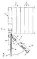
- FIG. 10is front elevation view of the cable management panel of FIG. 1 , shown in an application wherein the panel is vertically mounted;
- FIG. 11is a front elevation view of the cable management panel of FIG. 10 , shown with the drawer in an open position, and the tray of the drawer in a pivoted position;
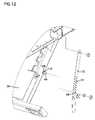
- FIG. 12is an enlarged detail view of FIG. 7 , schematically representing an alternative biasing arrangement of the cable management panel;
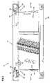
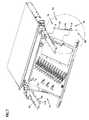
- FIG. 13is a partially exploded, front perspective view of another embodiment of a cable management panel, according to the principles of the present disclosure.
- FIG. 14is an enlarged detail view of FIG. 13 ;
- FIG. 15is an enlarged perspective view of a portion of the cable management panel of FIG. 13 ;
- FIG. 16is a schematic representation of a portion of a connection arrangement shown in FIG. 15 .
- the panel 10includes a frame or chassis 12 having mounting brackets 14 .
- the mounting brackets 14are used to mount the panel 10 to a telecommunication structure, such as a telecommunication rack or frame.
- the cable management panel 10can also be configured for mounting within a cabinet or enclosure, for example. Details of an example mounting bracket arrangement that can be used in accordance with the principles disclosed are described in U.S. Publication No. 2005/0025444, the disclosure of which is incorporated herein by reference.
- the chassis 12 of the cable management panel 10has a front 16 , opposite sides 18 , and a rear 20 .
- the sides 18define cable access openings 22 (see also FIG. 3 ) through which cables are routed into or out from the chassis 12 .
- the chassis 12further includes a drawer 26 that slides between an open position ( FIGS. 1 and 3 ) and a closed position ( FIG. 2 ). In the closed position, cables contained within an interior region 24 of the drawer 26 are enclosed and protected. In the open position, the cables can be accessed for maintenance purposes, for example.
- the drawer 26 of the cable management panel 10includes a front 33 , a rear 34 , a bottom tray (e.g., base plate or panel) 36 , and sides 38 .
- the sides 38 and rear 34 of the drawergenerally define a drawer frame 46 to which the bottom tray 36 is attached.
- the front 33 of the drawer 26is defined by an upright front drawer panel 40 that is attached to the tray 36 .
- the upright front drawer panel 40encloses the interior region 24 of the drawer 26 when the drawer is in the closed position. While the sides 38 of the drawer 26 are open, the sides 18 of the chassis are constructed to enclose the interior region 24 of the drawer 26 when the drawer is in the closed position.
- the open sides 38 of the drawer 26are provided to allow for cable entry and exit, and prevent cable damage during sliding movement of the drawer 26 .
- Radius limiters 58are located at the sides 38 of the drawer 26 for managing the exiting and entering cables during sliding movement of the drawer.
- the radius limiters 58also act as guides for cables passing through the access openings 22 , and protect the cables from damage by limiting cable bending beyond a minimum bend radius.
- the open sides 38 of the drawer 26are generally defined by horizontal side plates 42 .
- the side plates 42include longitudinal slots 52 .
- the longitudinal slots 52cooperate with the radius limiters 58 on each side of drawer 26 .
- the radius limiters 58are moveably mounted relative to the chassis 12 and drawer 26 .
- movement of the radius limiters 58is controlled in a synchronized manner relative to the movement of the drawer 26 . Further details of example drawers having radius limiters, and drawers having radius limiters with synchronized movement are described in U.S. Pat. Nos. 6,438,310; 6,504,988; and 7,079,744; the disclosures of which are each incorporated herein by reference.
- the drawer 26 in the illustrated embodimentincludes a variety of cable management elements 60 (e.g., cable management components or structures and distribution components or devices).
- the interior region 24 of the drawer 26is sized for receiving the cable management elements 60 .
- the cables and cable management devices or elements 60 in the interior region 24are protected.
- FIG. 1illustrates one tray embodiment having various types of cable management elements 60 .
- the elements 60include cable retainers 62 , a splice tray enclosure 64 housing splice trays, and adapters or connector holders 66 at which fiber optic connectors are mounted or located.
- the drawer 26can be customized to include numerous forms of cable management elements 60 to accommodate the particular needs of the user.
- examples of other cable management elementsinclude other constructions, assemblies, and devices for storing the cables or connecting the cables to other cables; and/or other fiber optic devices, such as attenuators, couplers, switches, wave divisions multiplexers (WDMs), and splitters/combiners.
- WDMswave divisions multiplexers
- the drawer 26 of the present cable management panel 10slides relative to the chassis 12 via two drawer slide assemblies 28 (see also FIGS. 6 and 9 ).
- the drawer slide assemblies 28are located adjacent to the opposite sides 18 of the chassis 12 .
- Latches 30are provided adjacent to both sides 38 of the drawer 26 .
- the latches 30secure the drawer 26 in the closed position by engaging a side hole 32 ( FIG. 3 ) located at the side 18 of the chassis 12 .
- the two drawer slide assemblies 28each include three slide rails. Further details of one type of slide assembly that can be used are described in U.S. Publication No. 2005/0025444; previously incorporated herein by reference. Other slide assemblies that can be used are described in U.S. application Ser. No. 11/543,457; which application is also incorporated herein by reference.
- the illustrated drawer slide assemblies 28each include a stop arrangement (not shown).
- the stop arrangementlimits the opening sliding movement of the drawer 26 beyond the open position to prevent inadvertent separation from the chassis 12 .
- the stop arrangementis an integral function of the drawer slide assembly 28 . Further details of such an arrangement are described in U.S. Publication No. 2005/0025444; previously incorporated herein by reference.
- the drawer 26has a drawer depth D 1 ( FIG. 3 ) that extends between the front 33 ( FIG. 1 ) of the drawer and the rear 34 of the drawer.
- the tray 36has a tray depth D 2 ( FIG. 3 ) that extends a majority of the depth D 1 of the drawer 26 .
- the depth D 2 of the trayextends a substantial majority of the depth D 1 of the drawer 26 .
- the tray 36can be selectively pivoted from a first planar orientation, as shown in FIG. 1 , to a second non-planar orientation, as shown in FIG. 4 .
- the second “non-planar” orientationis an orientation that is “not co-planar” with the plane defined by the tray 36 when the tray is in a non-pivoted position, i.e. the first planar orientation.
- the tray 36 of the drawer 26is oriented in a generally horizontal orientation, as shown in FIG. 3 .
- the tray 36can be selectively pivoted to a non-horizontal orientation, when the drawer is in the open position, to provide access to the cable management elements 60 mounted on the tray.
- the tray 36is constructed to selectively hinge or pivot about an axis X-X ( FIG. 5 ), as represented by arrow A ( FIG. 4 ).
- a hinge or pivot mechanism 44FIG. 5 ) that connects the tray 36 to the rear 34 of the drawer defines the axis X-X.
- the hinge 44is arranged such that tray 36 pivots in a direction away from the frame 46 (e.g., the side plates 42 ) of the drawer 26 .
- the pivoting tray 36provides adaptable access to, for example, the connector holders 66 or connector locations, or other elements 60 , mounted on the tray.
- the drawer 26 of the cable management panel 10includes a connection arrangement 70 that limits the pivotal movement of the tray 36 relative to the frame 46 of the drawer 26 .
- the connection arrangement 70is a pin and slide connection that releaseably locks the tray 36 in both the non-pivoted position ( FIG. 3 ) and a pivoted position ( FIG. 4 ).
- the connection arrangement 70generally includes a linkage or lever arm 72 and a pin assembly 76 .
- the lever arm 72has a first end 78 and a second end 80 .
- the first end 78 of the lever arm 72is pivotally attached to a flange 82 of the side plate 42 of the drawer 26 (see also FIG. 5 ).
- the lever arm 72is also slidably attached to the tray 36 adjacent to the second end 80 of the arm. That is, the lever arm 72 defines a slide or slot 74 that cooperates with the pin assembly 76 to provides a pin and slot connection between the tray 36 and the drawer frame 46 .
- the pin assembly 76 of the connection arrangement 70includes a bushing or plug body 86 having a first smaller diameter portion 102 and a second larger diameter portion 104 .
- the plug body 86is mounted on a pin 84 , which is attached or affixed to the tray 36 .
- a lock nut 88can be used to secure the plug body 86 to the pin 84 .
- connection arrangement 70also includes a lock piece 90 .
- the lock piece 90is secured to the second end 80 of the lever arm 72 . While in the illustrated embodiment, the lock piece 90 is a separate piece from that of the lever arm 72 , it is contemplated that the lock piece can be an integral construction of the lever arm.
- the pin assembly 76functions to releaseably lock the tray 36 in the pivoted position, while the lock piece 90 functions to releaseably lock the tray 36 in the non-pivoted position.
- the lever arm 72 of the connection arrangement 70is flexibly constructed.
- the lever arm 72can be constructed of spring steel, for example, or in the alternative, can be of a molded construction.
- the slot 74 of the lever arm 72has a slide portion 96 and an end portion 98 .
- the slide portion 96 of the slot 74corresponds in size to the smaller diameter portion 102 of the plug body 86 of the pin assembly 76 .
- the end portion 98 of the slot 74corresponds in size to the larger diameter portion 104 of the plug body 86 .
- the second end 80 of the lever arm 72is a biased end having a formed angular construction that acts as a leaf-type spring.
- the lever arm 72is angled in a region 106 at an approximate 2 degree offset from the first end 78 of the arm.
- FIG. 9the drawer 26 is shown in the open position with the tray 36 in the non-pivoted position.
- the tray 36is locked in this non-pivoted position via the lock piece 90 .
- the lock piece 90engages a corresponding aperture or hole 92 (see also FIG. 5 ) formed in the flange 82 of the side plate 42 to lock the tray 36 in the non-pivoted position.
- the biased end 80 of the lever arm 72is flexed inward toward the tray 36 of the drawer 26 , and retained by the larger diameter portion 104 ( FIG. 8 ) of the pin assembly 76 .
- the biased end 80 of the lever arm 72is squeezed or moved inward toward the tray 36 , as only the smaller portion diameter 102 of the pin assembly 76 fits within the slide portion 96 of the slot 74 .
- the larger diameter portion 104 of the pin assemblyprevents the biased end 80 from springing back or moving outward from the tray 36 .
- the lock piece 90 at the biased end 80 of the lever arm 72is thereby also retained in position, i.e., in engagement with the hole 92 so that the tray 36 remains locked in the non-pivoted position.
- the flexible construction of the lever arm 72permits a technician to release the tray 36 from the locked non-pivoted position by flexing the lever arm 72 outward from the tray 36 .
- the lever armis, in essence, flexed around the larger diameter portion 104 of the pin assembly 76 in a direction away from the flange 82 of the side plate 42 .
- An angled tab 94is provided at the second end 80 of the arm to assist the technician in grasping and flexing the lever arm. The outward flexure of the lever arm 72 disengages the lock piece 90 from the aperture 92 .
- the tray 36can be pivoted to the pivoted position shown in FIG. 5 . While pivoting the tray 36 , the smaller diameter portion 102 of the plug body 86 slides within the slide portion 96 of the slot 74 . Pivoting motion of the tray 36 is limited at a point where the pin assembly 76 seats within the end portion 98 of the slot 74 .
- the connection arrangement 70can be designed to permit the tray 36 to pivot between about 0 degrees and 60 degrees relative to the non-pivoted position. In the illustrated embodiment, the tray 36 pivots approximately 45 degrees relative to the non-pivoted position.
- the tray 36automatically locks into place. That is, in the pivoted position, the biased end 80 of the lever arm 72 is no longer constrained by the plug body 86 . Instead, as shown in FIG. 6 , the end portion 98 of the slot 74 now moves laterally outward to position about or engage the larger diameter 104 of the plug body. The lateral outward movement is caused by the biased construction of the flexible arm. Because the slide portion 96 of the slot 74 is sized to receive only the smaller diameter portion 102 of the pin assembly 76 , the tray 36 is thereby locked in the pivoted position. This is desirable during installation and maintenance procedures as the technician will be, for example, pulling on cables attached to the tray.
- the tray 36can automatically lock into the pivoted position via a spring assembly.
- the end portion 98 of the slot 74 of the lever arm 72can be biased outward by a spring 108 .
- the spring 108is retained about the pin body 84 attached to the tray 36 ; and a washer 110 is positioned between the spring 108 and the lever arm 72 .
- the spring 108can assist in laterally biasing the angled lever arm 72 or can solely provide the biasing force onto a non-angled lever arm.
- the lever arm 72is simply flexed inward toward the tray 36 such that the slot 74 aligns with the smaller diameter portion 102 of the plug body 86 .
- the smaller diameter portion of the plug body 86then slides upward within the slide portion 96 of the slot 74 as the tray 36 is pivoted back to the non-pivoted position.
- a ramped surface 100(see FIG. 6 and 8 ) of the lock piece 90 contacts an edge 106 ( FIG. 7 ) of the flange 82 of the side plate 42 .
- the ramped surface 100acts as a guide to ease the engagement between the side plate 42 and the lever arm 72 .
- the lock piece 90seats within the aperture 92 formed in the flange 82 to automatically lock the tray 36 in the non-pivoted position.
- the present cable management panel 10provides adaptable access to cable management elements protected within the panel. What is meant by adaptable is that the present cable management panel 10 can be used simply as a drawer that slides in and out of the chassis, or can be used by employing the features of the pivoting tray, as described above.
- the pivoting tray featureis particularly convenient in applications where the panel 10 is stacked upon other panels (as schematically represented in FIG. 4 ) or mounted above a comfortable working height.
- the techniciancan more easily access higher mounted panels by simply sliding the drawer out from the chassis 12 , and pivoting the drawer bottom or tray 36 downward. In the pivoted position, the cable management elements 60 mounted on the pivoted tray 36 are more easily accessed as the bottom of the drawer 26 (i.e. the tray 36 ) now faces the technician.
- the cable management panel 10can be vertically mounted such that the drawer 26 and tray 36 are oriented in a generally vertical orientation.
- the techniciansimply slides the drawer 26 out from the chassis 12 , and pivots the chassis either to the right, or to the left (as shown by arrow B in FIG. 11 ), depending upon the vertical orientation of the panel 10 .
- This arrangementis convenient in applications where lateral space, i.e., space located adjacent to the panels, is limited.
- the techniciancan instead stand in front of the drawer and pivot the vertical tray 36 such that the interior region 24 of the drawer 26 forwardly faces the technician.
- FIG. 13another embodiment of a cable management panel 210 is illustrated.
- the cable management panel 210is similar to the panel 10 of FIGS. 1-9 , with the exception of the connection arrangement that limits the pivotal movement of the tray relative to the frame of the drawer.
- the cable management panel 210includes a chassis 212 and a drawer 226 .
- the drawer 226 of the cable management panel 210has a front 233 , a rear 234 , a bottom tray (e.g., base plate or panel) 236 , and sides 238 .
- the sides 238 and rear 234 of the drawergenerally define a drawer frame 246 to which the bottom tray 236 is attached.
- the front 233 of the drawer 226is defined by an upright front drawer panel 240 that is attached to the tray 236 .
- the upright front drawer panel 240encloses an interior region 224 of the drawer 226 when the drawer is in the closed position.
- the tray 236can be selectively pivoted from a first planar orientation, as shown in FIG. 15 , to a second non-planar orientation, as shown in FIG. 13 .
- connection arrangement 270different from that of the previous embodiment.
- the connection arrangement 270includes a first latching connection 214 that releaseably locks that tray 236 in the non-pivoted position ( FIG. 15 ) and a separate second connection 216 that releaseably locks the tray 236 in the pivoted position ( FIG. 13 ).
- Each of the first and second connections 214 , 216is independent of the other; i.e., is a separate component that functions independent of the other component.
- the first connection 214 of the connection arrangement 270includes a first lever arm 218 .
- the lever arm 218has a first end 220 and a second end 222 .
- the first end 220 of the lever arm 218is non-pivotally attached to a flange 282 ( FIG. 13 ) of a side plate 242 of the drawer 226 at an attachment location 230 .
- a lock piece 290( FIG. 14 ) is secured to the second end 222 of the lever arm 218 .
- the lever arm 218can include a guide or locating notch 254 sized to receive locating structure 256 (e.g., a lip) of the lock piece 290 .
- the lock piece 290is a separate piece from that of the lever arm 218 , it is contemplated that the lock piece can be an integral construction of the lever arm.
- the lock piece 290functions to releaseably lock the tray 236 in the non-pivoted position.
- the lock piece 290engages a corresponding aperture or hole 292 (see FIGS. 13 and 16 ) formed in the tray 236 of the drawer 226 to lock the tray 236 in the non-pivoted position.
- the second connection 216 of the connection arrangement 270generally includes a second lever arm 272 and a pin assembly 276 .
- the second lever arm 272has a first end 278 and a second end 280 .
- the first end 278 of the lever arm 272is pivotally attached to the flange 282 of the side plate 242 of the drawer 226 at an attachment location 258 .
- the lever arm 272is also slidably attached to the tray 236 adjacent to the second end 280 of the arm. That is, the lever arm 272 defines a slide or slot 274 ( FIG. 14 ) that cooperates with the pin assembly 276 to provides a pin and slot connection between the tray 236 and the drawer frame 246 .
- each of the first and second lever arms 218 , 272 of the connection arrangement 270is flexibly constructed.
- the lever arms 218 , 272can be constructed of spring steel, for example, or in the alternative, can be of a molded construction.
- the second end 280 of the lever arm 272is a biased end having a formed angular construction that acts as a leaf-type spring.
- the second end 280 of the lever arm 272is angled at an approximate 2 degree offset from the first end 278 of the arm.
- the pin assembly 276 of the connection arrangement 270includes a bushing or plug body 286 having a first smaller diameter portion 244 and a second larger diameter portion 248 .
- the plug body 286is mounted on a pin 284 , which is attached or affixed to the bottom tray 236 .
- the flexible construction of the first lever arm 218permits a technician to release the tray 236 from the locked non-pivoted position by flexing the lever arm 218 in a direction C ( FIG. 16 ) outward from the tray 236 .
- An angled tab 294is provided at the second end 222 of the arm to assist the technician in grasping and flexing the lever arm. The outward flexure of the lever arm 218 disengages the lock piece 290 from the aperture 292 of the bottom tray 236 .
- the tray 236When the lock piece 290 is disengaged from the aperture 292 , the tray 236 can be pivoted to the pivoted position shown in FIG. 13 . While pivoting the tray 236 , the smaller diameter portion 244 of the plug body 286 of the second connection 216 slides within a slide portion 296 ( FIG. 14 ) of the slot 274 . Pivoting motion of the tray 236 is limited at a point where the pin assembly 276 seats within an end portion 298 of the slot 274 .
- the second end 280 of the second lever arm 272is biased outward. While the tray 236 is pivoting downward, the smaller portion diameter 244 of the pin assembly 276 slides within the slide portion 296 of the slot 274 . The larger diameter portion 248 of the pin assembly prevents the biased end 280 of the lever arm from springing or moving outward from the tray 236 .
- the tray 236automatically locks into place. That is, in the pivoted position, the biased end 280 of the lever arm 272 is no longer constrained by the plug body 286 . Instead, the end portion 298 of the slot 274 now moves laterally outward to position about or engage the larger diameter 248 of the plug body. The lateral outward movement is caused by the biased construction of the flexible arm 272 . Because the slide portion 296 of the slot 274 is sized to receive only the smaller diameter portion 244 of the pin assembly 276 , the tray 236 is thereby locked in the pivoted position.
- the lever arm 272is simply flexed inward toward the tray 236 such that the slot 274 aligns with the smaller diameter portion 244 of the plug body 286 .
- the smaller diameter portion of the plug body 286then slides upward within the slide portion 296 of the slot 274 as the tray 236 is pivoted back to the non-pivoted position.
- a ramped surface 250( FIG. 16 ) of the lock piece 290 contacts an edge 252 (see also FIG. 13 ) of the bottom tray 236 .
- the ramped surface 250acts as a guide to ease the engagement between the bottom tray 236 and the locking piece 290 , and gradually flex the lever arm 218 outward.
- the lock piece 290seats within the aperture 292 formed in the bottom tray 236 to automatically lock the tray 236 in the non-pivoted position.
Landscapes
- Physics & Mathematics (AREA)
- General Physics & Mathematics (AREA)
- Optics & Photonics (AREA)
- Drawers Of Furniture (AREA)
- Light Guides In General And Applications Therefor (AREA)
Abstract
Description
Claims (21)
Priority Applications (2)
| Application Number | Priority Date | Filing Date | Title |
|---|---|---|---|
| US11/640,477US7418182B2 (en) | 2006-10-10 | 2006-12-15 | Cable management drawer with access panel |
| US12/218,500US7715680B2 (en) | 2006-10-10 | 2008-07-14 | Cable management drawer with access panel |
Applications Claiming Priority (2)
| Application Number | Priority Date | Filing Date | Title |
|---|---|---|---|
| US11/546,538US7437049B2 (en) | 2006-10-10 | 2006-10-10 | Cable management drawer with access panel |
| US11/640,477US7418182B2 (en) | 2006-10-10 | 2006-12-15 | Cable management drawer with access panel |
Related Parent Applications (1)
| Application Number | Title | Priority Date | Filing Date |
|---|---|---|---|
| US11/546,538Continuation-In-PartUS7437049B2 (en) | 2006-10-10 | 2006-10-10 | Cable management drawer with access panel |
Related Child Applications (1)
| Application Number | Title | Priority Date | Filing Date |
|---|---|---|---|
| US12/218,500ContinuationUS7715680B2 (en) | 2006-10-10 | 2008-07-14 | Cable management drawer with access panel |
Publications (2)
| Publication Number | Publication Date |
|---|---|
| US20080085094A1 US20080085094A1 (en) | 2008-04-10 |
| US7418182B2true US7418182B2 (en) | 2008-08-26 |
Family
ID=39295543
Family Applications (2)
| Application Number | Title | Priority Date | Filing Date |
|---|---|---|---|
| US11/640,477ActiveUS7418182B2 (en) | 2006-10-10 | 2006-12-15 | Cable management drawer with access panel |
| US12/218,500ActiveUS7715680B2 (en) | 2006-10-10 | 2008-07-14 | Cable management drawer with access panel |
Family Applications After (1)
| Application Number | Title | Priority Date | Filing Date |
|---|---|---|---|
| US12/218,500ActiveUS7715680B2 (en) | 2006-10-10 | 2008-07-14 | Cable management drawer with access panel |
Country Status (1)
| Country | Link |
|---|---|
| US (2) | US7418182B2 (en) |
Cited By (74)
| Publication number | Priority date | Publication date | Assignee | Title |
|---|---|---|---|---|
| US20080093958A1 (en)* | 2006-10-20 | 2008-04-24 | Peterson Karl J | High density telecommunications mounting drawer |
| US20090022470A1 (en)* | 2006-10-10 | 2009-01-22 | Adc Telecommunications, Inc. | Cable management drawer with access panel |
| US20090310929A1 (en)* | 2007-10-10 | 2009-12-17 | Adc Telecommunications, Inc. | Optical fiber interconnection apparatus |
| US20100061691A1 (en)* | 2008-09-08 | 2010-03-11 | Ortronics, Inc. | Horizontal fiber optic patching assembly |
| US7856166B2 (en) | 2008-09-02 | 2010-12-21 | Corning Cable Systems Llc | High-density patch-panel assemblies for optical fiber telecommunications |
| US20110211799A1 (en)* | 2008-10-27 | 2011-09-01 | Mark Edward Conner | Variably configurable and modular local convergence point |
| US20110228473A1 (en)* | 2010-02-12 | 2011-09-22 | Chad Anderson | Communications bladed panel systems |
| US8184938B2 (en) | 2008-08-29 | 2012-05-22 | Corning Cable Systems Llc | Rear-installable fiber optic modules and equipment |
| US8280216B2 (en) | 2009-05-21 | 2012-10-02 | Corning Cable Systems Llc | Fiber optic equipment supporting moveable fiber optic equipment tray(s) and module(s), and related equipment and methods |
| US8433171B2 (en) | 2009-06-19 | 2013-04-30 | Corning Cable Systems Llc | High fiber optic cable packing density apparatus |
| US8452148B2 (en) | 2008-08-29 | 2013-05-28 | Corning Cable Systems Llc | Independently translatable modules and fiber optic equipment trays in fiber optic equipment |
| US8542973B2 (en) | 2010-04-23 | 2013-09-24 | Ccs Technology, Inc. | Fiber optic distribution device |
| US8593828B2 (en) | 2010-02-04 | 2013-11-26 | Corning Cable Systems Llc | Communications equipment housings, assemblies, and related alignment features and methods |
| US8625950B2 (en) | 2009-12-18 | 2014-01-07 | Corning Cable Systems Llc | Rotary locking apparatus for fiber optic equipment trays and related methods |
| US8660397B2 (en) | 2010-04-30 | 2014-02-25 | Corning Cable Systems Llc | Multi-layer module |
| US8662760B2 (en) | 2010-10-29 | 2014-03-04 | Corning Cable Systems Llc | Fiber optic connector employing optical fiber guide member |
| US8699838B2 (en) | 2009-05-14 | 2014-04-15 | Ccs Technology, Inc. | Fiber optic furcation module |
| US8705926B2 (en) | 2010-04-30 | 2014-04-22 | Corning Optical Communications LLC | Fiber optic housings having a removable top, and related components and methods |
| US8712206B2 (en) | 2009-06-19 | 2014-04-29 | Corning Cable Systems Llc | High-density fiber optic modules and module housings and related equipment |
| US8718436B2 (en) | 2010-08-30 | 2014-05-06 | Corning Cable Systems Llc | Methods, apparatuses for providing secure fiber optic connections |
| US8879881B2 (en) | 2010-04-30 | 2014-11-04 | Corning Cable Systems Llc | Rotatable routing guide and assembly |
| US8909019B2 (en) | 2012-10-11 | 2014-12-09 | Ccs Technology, Inc. | System comprising a plurality of distribution devices and distribution device |
| US8913866B2 (en) | 2010-03-26 | 2014-12-16 | Corning Cable Systems Llc | Movable adapter panel |
| US8953924B2 (en) | 2011-09-02 | 2015-02-10 | Corning Cable Systems Llc | Removable strain relief brackets for securing fiber optic cables and/or optical fibers to fiber optic equipment, and related assemblies and methods |
| US8989547B2 (en) | 2011-06-30 | 2015-03-24 | Corning Cable Systems Llc | Fiber optic equipment assemblies employing non-U-width-sized housings and related methods |
| US8985862B2 (en) | 2013-02-28 | 2015-03-24 | Corning Cable Systems Llc | High-density multi-fiber adapter housings |
| US8995812B2 (en) | 2012-10-26 | 2015-03-31 | Ccs Technology, Inc. | Fiber optic management unit and fiber optic distribution device |
| US9008485B2 (en) | 2011-05-09 | 2015-04-14 | Corning Cable Systems Llc | Attachment mechanisms employed to attach a rear housing section to a fiber optic housing, and related assemblies and methods |
| US9004778B2 (en) | 2012-06-29 | 2015-04-14 | Corning Cable Systems Llc | Indexable optical fiber connectors and optical fiber connector arrays |
| US9020320B2 (en) | 2008-08-29 | 2015-04-28 | Corning Cable Systems Llc | High density and bandwidth fiber optic apparatuses and related equipment and methods |
| US9022814B2 (en) | 2010-04-16 | 2015-05-05 | Ccs Technology, Inc. | Sealing and strain relief device for data cables |
| US9042702B2 (en) | 2012-09-18 | 2015-05-26 | Corning Cable Systems Llc | Platforms and systems for fiber optic cable attachment |
| US9038832B2 (en) | 2011-11-30 | 2015-05-26 | Corning Cable Systems Llc | Adapter panel support assembly |
| US9049500B2 (en) | 2012-08-31 | 2015-06-02 | Corning Cable Systems Llc | Fiber optic terminals, systems, and methods for network service management |
| US9059578B2 (en) | 2009-02-24 | 2015-06-16 | Ccs Technology, Inc. | Holding device for a cable or an assembly for use with a cable |
| US9075216B2 (en) | 2009-05-21 | 2015-07-07 | Corning Cable Systems Llc | Fiber optic housings configured to accommodate fiber optic modules/cassettes and fiber optic panels, and related components and methods |
| US9075217B2 (en) | 2010-04-30 | 2015-07-07 | Corning Cable Systems Llc | Apparatuses and related components and methods for expanding capacity of fiber optic housings |
| US9116324B2 (en) | 2010-10-29 | 2015-08-25 | Corning Cable Systems Llc | Stacked fiber optic modules and fiber optic equipment configured to support stacked fiber optic modules |
| US9213161B2 (en) | 2010-11-05 | 2015-12-15 | Corning Cable Systems Llc | Fiber body holder and strain relief device |
| US9219546B2 (en) | 2011-12-12 | 2015-12-22 | Corning Optical Communications LLC | Extremely high frequency (EHF) distributed antenna systems, and related components and methods |
| US9250409B2 (en) | 2012-07-02 | 2016-02-02 | Corning Cable Systems Llc | Fiber-optic-module trays and drawers for fiber-optic equipment |
| US9279951B2 (en) | 2010-10-27 | 2016-03-08 | Corning Cable Systems Llc | Fiber optic module for limited space applications having a partially sealed module sub-assembly |
| US9285557B2 (en) | 2012-06-27 | 2016-03-15 | Tyco Electronics Raychem Bvba | High density telecommunications chassis with cable management |
| US9323020B2 (en) | 2008-10-09 | 2016-04-26 | Corning Cable Systems (Shanghai) Co. Ltd | Fiber optic terminal having adapter panel supporting both input and output fibers from an optical splitter |
| US9521766B2 (en) | 2012-06-27 | 2016-12-13 | CommScope Connectivity Belgium BVBA | High density telecommunications systems with cable management and heat dissipation features |
| US9519118B2 (en) | 2010-04-30 | 2016-12-13 | Corning Optical Communications LLC | Removable fiber management sections for fiber optic housings, and related components and methods |
| US20160370552A1 (en)* | 2014-02-14 | 2016-12-22 | Tyco Electronics Uk Ltd. | Managed connectivity in optical distribution frame |
| US9541726B2 (en) | 2013-04-24 | 2017-01-10 | Adc Czech Republic, S.R.O. | Optical fiber distribution system |
| US9547145B2 (en) | 2010-10-19 | 2017-01-17 | Corning Optical Communications LLC | Local convergence point for multiple dwelling unit fiber optic distribution network |
| US9568699B2 (en) | 2013-01-29 | 2017-02-14 | CommScope Connectivity Belgium BVBA | Optical fiber distribution system |
| US9632270B2 (en) | 2010-04-30 | 2017-04-25 | Corning Optical Communications LLC | Fiber optic housings configured for tool-less assembly, and related components and methods |
| US9645317B2 (en) | 2011-02-02 | 2017-05-09 | Corning Optical Communications LLC | Optical backplane extension modules, and related assemblies suitable for establishing optical connections to information processing modules disposed in equipment racks |
| US9690065B2 (en) | 2014-09-12 | 2017-06-27 | Panduit Corp. | High density fiber enclosure and method |
| US9720195B2 (en) | 2010-04-30 | 2017-08-01 | Corning Optical Communications LLC | Apparatuses and related components and methods for attachment and release of fiber optic housings to and from an equipment rack |
| US10110307B2 (en) | 2012-03-02 | 2018-10-23 | Corning Optical Communications LLC | Optical network units (ONUs) for high bandwidth connectivity, and related components and methods |
| US10215944B2 (en) | 2016-06-30 | 2019-02-26 | Panduit Corp. | Modular fiber optic tray |
| US10261281B2 (en) | 2015-04-03 | 2019-04-16 | CommScope Connectivity Belgium BVBA | Telecommunications distribution elements |
| US10409020B2 (en) | 2013-04-24 | 2019-09-10 | CommScope Connectivity Belgium BVBA | Universal mounting mechanism for mounting a telecommunications chassis to a telecommunciations fixture |
| US10948675B2 (en)* | 2011-10-07 | 2021-03-16 | Commscope Technologies Llc | Slidable fiber optic connection module with cable slack management |
| US11294136B2 (en) | 2008-08-29 | 2022-04-05 | Corning Optical Communications LLC | High density and bandwidth fiber optic apparatuses and related equipment and methods |
| US11409067B2 (en) | 2018-08-31 | 2022-08-09 | CommScope Connectivity Belgium BVBA | Frame assemblies for optical fiber distribution elements |
| US11448845B2 (en) | 2018-08-31 | 2022-09-20 | CommScope Connectivity Belgium BVBA | Frame assemblies for optical fiber distribution elements |
| US11448844B2 (en) | 2018-08-31 | 2022-09-20 | CommScope Connectivity Belgium BVBA | Frame assemblies for optical fiber distribution elements |
| US11448831B2 (en) | 2018-08-31 | 2022-09-20 | CommScope Connectivity Belgium BVBA | Frame assemblies for optical fiber distribution elements |
| US11635578B2 (en) | 2018-04-17 | 2023-04-25 | CommScope Connectivity Belgium BVBA | Telecommunications distribution elements |
| US11852882B2 (en) | 2018-02-28 | 2023-12-26 | Commscope Technologies Llc | Packaging assembly for telecommunications equipment |
| US11947177B2 (en) | 2019-01-25 | 2024-04-02 | CommScope Connectivity Belgium BVBA | Frame assemblies for optical fiber distribution elements |
| US12007615B2 (en) | 2018-10-23 | 2024-06-11 | CommScope Connectivity Belgium BVBA | Frame assemblies for optical fiber distribution elements |
| US12019277B2 (en) | 2012-09-28 | 2024-06-25 | Commscope Technologies Llc | Manufacture and testing of fiber optic cassette |
| US12050358B2 (en) | 2018-08-31 | 2024-07-30 | CommScope Connectivity Belgium BVBA | Frame assemblies for optical fiber distribution elements |
| US12099246B2 (en) | 2020-01-24 | 2024-09-24 | CommScope Connectivity Belgium BVBA | Telecommunications distribution elements |
| US12130487B2 (en)* | 2012-10-05 | 2024-10-29 | Commscope Asia Holdings B.V. | Flexible optical circuit, cassettes, and methods |
| US12174443B2 (en) | 2020-01-22 | 2024-12-24 | CommScope Connectivity Belgium BVBA | Cable termination units for optical fiber distribution elements |
| US12276858B2 (en) | 2017-10-02 | 2025-04-15 | Commscope Technologies Llc | Fiber optic circuit and preparation method |
Families Citing this family (22)
| Publication number | Priority date | Publication date | Assignee | Title |
|---|---|---|---|---|
| WO2008029291A2 (en)* | 2006-06-23 | 2008-03-13 | Adc Gmbh | Slide and tilt mechanism for a telecommunications panel |
| US8798427B2 (en) | 2007-09-05 | 2014-08-05 | Corning Cable Systems Llc | Fiber optic terminal assembly |
| US8290330B2 (en)* | 2008-09-05 | 2012-10-16 | Adc Gmbh | Patch panel assembly |
| WO2010080745A1 (en)* | 2009-01-08 | 2010-07-15 | Afl Telecommunications Llc | Field terminated fiber patch panel for rack and wall mounting |
| US8014646B2 (en)* | 2009-01-26 | 2011-09-06 | Commscope, Inc. Of North Carolina | Telecommunications patching systems with high density patching modules |
| US20100220967A1 (en)* | 2009-02-27 | 2010-09-02 | Cooke Terry L | Hinged Fiber Optic Module Housing and Module |
| EP2237091A1 (en)* | 2009-03-31 | 2010-10-06 | Corning Cable Systems LLC | Removably mountable fiber optic terminal |
| BRPI1012833A2 (en)* | 2009-06-08 | 2018-03-06 | Commscope Inc North Carolina | communication connection system |
| US8385710B2 (en) | 2009-11-12 | 2013-02-26 | Panduit Corp. | Fiber tray |
| US9547144B2 (en) | 2010-03-16 | 2017-01-17 | Corning Optical Communications LLC | Fiber optic distribution network for multiple dwelling units |
| US8792767B2 (en) | 2010-04-16 | 2014-07-29 | Ccs Technology, Inc. | Distribution device |
| CN102985859A (en)* | 2010-04-23 | 2013-03-20 | Ccs技术公司 | Removable fiber optic splice tray |
| DE202010007778U1 (en)* | 2010-06-09 | 2010-10-07 | CCS Technology, Inc., Wilmington | Device for handling data conductors |
| US10082636B2 (en)* | 2012-09-21 | 2018-09-25 | Commscope Technologies Llc | Slidable fiber optic connection module with cable slack management |
| ES2768340T3 (en) | 2013-10-18 | 2020-06-22 | CommScope Connectivity Belgium BVBA | Mounting system for telecommunication distribution elements |
| WO2015189384A1 (en)* | 2014-06-12 | 2015-12-17 | Tyco Electronics Raychem Bvba | Cable patch panel with movable retainer |
| US9516781B2 (en)* | 2015-02-19 | 2016-12-06 | All Systems Broadband, Inc. | Fiber optic shelf with a removable roof panel |
| US9914606B1 (en)* | 2016-10-14 | 2018-03-13 | Hewlett-Packard Development Company, L.P. | Media path jam clearing |
| US10798469B2 (en)* | 2017-01-12 | 2020-10-06 | IAP Worldwide Services, Inc. | Cable management system and apparatus for portable rack-mounted electronics |
| EP4509895A3 (en) | 2018-05-14 | 2025-06-18 | AFL Telecommunications LLC | Butt closures and organizer assemblies therefor |
| IT201900019139A1 (en)* | 2019-10-17 | 2021-04-17 | Prysmian Spa | MANAGEMENT SYSTEM FOR OPTICAL FIBERS |
| US11317715B2 (en)* | 2020-05-15 | 2022-05-03 | Lonman Auto Accessories Co., Ltd | Integrated inclinable goods shelf |
Citations (15)
| Publication number | Priority date | Publication date | Assignee | Title |
|---|---|---|---|---|
| US5071211A (en) | 1988-12-20 | 1991-12-10 | Northern Telecom Limited | Connector holders and distribution frame and connector holder assemblies for optical cable |
| US5167001A (en) | 1991-09-03 | 1992-11-24 | Northern Telecom Limited | Optical fiber storage and connector tray and shelf and tray assembly |
| US5490229A (en)* | 1993-12-08 | 1996-02-06 | At&T Ipm Corp. | Slidably mounted optical fiber distribution tray |
| US5497444A (en)* | 1994-01-21 | 1996-03-05 | Adc Telecommunications, Inc. | High-density fiber distribution frame |
| US6301424B1 (en) | 2000-04-13 | 2001-10-09 | Lucent Technologies Inc. | Distribution frame cable routing apparatus |
| US6438310B1 (en) | 2000-01-24 | 2002-08-20 | Adc Telecommunications, Inc. | Cable management panel with sliding drawer |
| US20020117942A1 (en) | 2000-12-19 | 2002-08-29 | Audibert Kevin Joseph | Rack mountable fiber splice and patch enclosure |
| US6504988B1 (en) | 2000-01-24 | 2003-01-07 | Adc Telecommunications, Inc. | Cable management panel with sliding drawer |
| US6792190B2 (en) | 2001-06-01 | 2004-09-14 | Telect, Inc. | High density fiber optic splitter/connector tray system |
| US20050025444A1 (en) | 2003-07-31 | 2005-02-03 | Barnes Kathleen M. | Slide arrangement for cable drawer |
| US6944389B2 (en)* | 2003-11-26 | 2005-09-13 | Corning Cable Systems Llc | Connector housing having a sliding tray with a hingeable portion |
| US20060018622A1 (en)* | 2004-07-22 | 2006-01-26 | Caveney Jack E | Front access punch down patch panel |
| US7031588B2 (en)* | 2004-04-27 | 2006-04-18 | Commscope Solutions Properties, Llc | Articulated high density fiber optic splice and termination shelf |
| US7079744B2 (en) | 2001-07-06 | 2006-07-18 | Adc Telecommunications, Inc. | Cable management panel with sliding drawer and methods |
| US20070031099A1 (en) | 2005-08-02 | 2007-02-08 | Herzog Daniel J | Cable management panel with rear entry |
Family Cites Families (5)
| Publication number | Priority date | Publication date | Assignee | Title |
|---|---|---|---|---|
| US7460758B2 (en)* | 2005-06-03 | 2008-12-02 | Telect Inc. | Fiber management system |
| US7349615B2 (en)* | 2006-08-25 | 2008-03-25 | Corning Cable Systems Llc | Fiber optic housing assembly for fiber optic connections comprising pivotable portion |
| US7391952B1 (en)* | 2006-08-31 | 2008-06-24 | Corning Cable Systems Llc | Pre-connectorized fiber optic cable network interconnection apparatus |
| US7437049B2 (en) | 2006-10-10 | 2008-10-14 | Adc Telecommunications, Inc. | Cable management drawer with access panel |
| US7418182B2 (en)* | 2006-10-10 | 2008-08-26 | Adc Telecommunications, Inc. | Cable management drawer with access panel |
- 2006
- 2006-12-15USUS11/640,477patent/US7418182B2/enactiveActive
- 2008
- 2008-07-14USUS12/218,500patent/US7715680B2/enactiveActive
Patent Citations (17)
| Publication number | Priority date | Publication date | Assignee | Title |
|---|---|---|---|---|
| US5071211A (en) | 1988-12-20 | 1991-12-10 | Northern Telecom Limited | Connector holders and distribution frame and connector holder assemblies for optical cable |
| US5167001A (en) | 1991-09-03 | 1992-11-24 | Northern Telecom Limited | Optical fiber storage and connector tray and shelf and tray assembly |
| US5490229A (en)* | 1993-12-08 | 1996-02-06 | At&T Ipm Corp. | Slidably mounted optical fiber distribution tray |
| US5497444A (en)* | 1994-01-21 | 1996-03-05 | Adc Telecommunications, Inc. | High-density fiber distribution frame |
| US5717810A (en)* | 1994-01-21 | 1998-02-10 | Adc Telecommunications, Inc. | High-density fiber distribution frame |
| USRE38311E1 (en)* | 1994-01-21 | 2003-11-11 | Adc Telecommunications, Inc. | High-density cable distribution frame |
| US6504988B1 (en) | 2000-01-24 | 2003-01-07 | Adc Telecommunications, Inc. | Cable management panel with sliding drawer |
| US6438310B1 (en) | 2000-01-24 | 2002-08-20 | Adc Telecommunications, Inc. | Cable management panel with sliding drawer |
| US6301424B1 (en) | 2000-04-13 | 2001-10-09 | Lucent Technologies Inc. | Distribution frame cable routing apparatus |
| US20020117942A1 (en) | 2000-12-19 | 2002-08-29 | Audibert Kevin Joseph | Rack mountable fiber splice and patch enclosure |
| US6792190B2 (en) | 2001-06-01 | 2004-09-14 | Telect, Inc. | High density fiber optic splitter/connector tray system |
| US7079744B2 (en) | 2001-07-06 | 2006-07-18 | Adc Telecommunications, Inc. | Cable management panel with sliding drawer and methods |
| US20050025444A1 (en) | 2003-07-31 | 2005-02-03 | Barnes Kathleen M. | Slide arrangement for cable drawer |
| US6944389B2 (en)* | 2003-11-26 | 2005-09-13 | Corning Cable Systems Llc | Connector housing having a sliding tray with a hingeable portion |
| US7031588B2 (en)* | 2004-04-27 | 2006-04-18 | Commscope Solutions Properties, Llc | Articulated high density fiber optic splice and termination shelf |
| US20060018622A1 (en)* | 2004-07-22 | 2006-01-26 | Caveney Jack E | Front access punch down patch panel |
| US20070031099A1 (en) | 2005-08-02 | 2007-02-08 | Herzog Daniel J | Cable management panel with rear entry |
Non-Patent Citations (1)
| Title |
|---|
| U.S. Appl. No. 11/543,457; inventor Barnes; filed Oct. 4, 2006; Slide Arrangement For Cable Drawer. |
Cited By (157)
| Publication number | Priority date | Publication date | Assignee | Title |
|---|---|---|---|---|
| US7715680B2 (en) | 2006-10-10 | 2010-05-11 | Adc Telecommunications, Inc. | Cable management drawer with access panel |
| US20090022470A1 (en)* | 2006-10-10 | 2009-01-22 | Adc Telecommunications, Inc. | Cable management drawer with access panel |
| US20080093958A1 (en)* | 2006-10-20 | 2008-04-24 | Peterson Karl J | High density telecommunications mounting drawer |
| US8727458B2 (en) | 2006-10-20 | 2014-05-20 | Adc Telecommunications, Inc. | High density telecommunications mounting drawer |
| US20090310929A1 (en)* | 2007-10-10 | 2009-12-17 | Adc Telecommunications, Inc. | Optical fiber interconnection apparatus |
| US11754796B2 (en) | 2008-08-29 | 2023-09-12 | Corning Optical Communications LLC | Independently translatable modules and fiber optic equipment trays in fiber optic equipment |
| US10606014B2 (en) | 2008-08-29 | 2020-03-31 | Corning Optical Communications LLC | Independently translatable modules and fiber optic equipment trays in fiber optic equipment |
| US10852499B2 (en) | 2008-08-29 | 2020-12-01 | Corning Optical Communications LLC | High density and bandwidth fiber optic apparatuses and related equipment and methods |
| US11086089B2 (en) | 2008-08-29 | 2021-08-10 | Corning Optical Communications LLC | High density and bandwidth fiber optic apparatuses and related equipment and methods |
| US10094996B2 (en) | 2008-08-29 | 2018-10-09 | Corning Optical Communications, Llc | Independently translatable modules and fiber optic equipment trays in fiber optic equipment |
| US8184938B2 (en) | 2008-08-29 | 2012-05-22 | Corning Cable Systems Llc | Rear-installable fiber optic modules and equipment |
| US9020320B2 (en) | 2008-08-29 | 2015-04-28 | Corning Cable Systems Llc | High density and bandwidth fiber optic apparatuses and related equipment and methods |
| US11092767B2 (en) | 2008-08-29 | 2021-08-17 | Corning Optical Communications LLC | High density and bandwidth fiber optic apparatuses and related equipment and methods |
| US11294136B2 (en) | 2008-08-29 | 2022-04-05 | Corning Optical Communications LLC | High density and bandwidth fiber optic apparatuses and related equipment and methods |
| US8452148B2 (en) | 2008-08-29 | 2013-05-28 | Corning Cable Systems Llc | Independently translatable modules and fiber optic equipment trays in fiber optic equipment |
| US11294135B2 (en) | 2008-08-29 | 2022-04-05 | Corning Optical Communications LLC | High density and bandwidth fiber optic apparatuses and related equipment and methods |
| US10120153B2 (en) | 2008-08-29 | 2018-11-06 | Corning Optical Communications, Llc | Independently translatable modules and fiber optic equipment trays in fiber optic equipment |
| US11609396B2 (en) | 2008-08-29 | 2023-03-21 | Corning Optical Communications LLC | High density and bandwidth fiber optic apparatuses and related equipment and methods |
| US10564378B2 (en) | 2008-08-29 | 2020-02-18 | Corning Optical Communications LLC | High density and bandwidth fiber optic apparatuses and related equipment and methods |
| US10126514B2 (en) | 2008-08-29 | 2018-11-13 | Corning Optical Communications, Llc | Independently translatable modules and fiber optic equipment trays in fiber optic equipment |
| US10222570B2 (en) | 2008-08-29 | 2019-03-05 | Corning Optical Communications LLC | Independently translatable modules and fiber optic equipment trays in fiber optic equipment |
| US9910236B2 (en) | 2008-08-29 | 2018-03-06 | Corning Optical Communications LLC | High density and bandwidth fiber optic apparatuses and related equipment and methods |
| US10416405B2 (en) | 2008-08-29 | 2019-09-17 | Corning Optical Communications LLC | Independently translatable modules and fiber optic equipment trays in fiber optic equipment |
| US10459184B2 (en) | 2008-08-29 | 2019-10-29 | Corning Optical Communications LLC | High density and bandwidth fiber optic apparatuses and related equipment and methods |
| US10422971B2 (en) | 2008-08-29 | 2019-09-24 | Corning Optical Communicatinos LLC | High density and bandwidth fiber optic apparatuses and related equipment and methods |
| US12072545B2 (en) | 2008-08-29 | 2024-08-27 | Corning Optical Communications LLC | High density and bandwidth fiber optic apparatuses and related equipment and methods |
| US10444456B2 (en) | 2008-08-29 | 2019-10-15 | Corning Optical Communications LLC | High density and bandwidth fiber optic apparatuses and related equipment and methods |
| US20110085776A1 (en)* | 2008-09-02 | 2011-04-14 | Eric Biribuze | High-Density Patch-Panel Assemblies for Optical Fiber Telecommunications |
| US7856166B2 (en) | 2008-09-02 | 2010-12-21 | Corning Cable Systems Llc | High-density patch-panel assemblies for optical fiber telecommunications |
| US8331752B2 (en) | 2008-09-02 | 2012-12-11 | Corning Cable Systems Llc | High-density patch-panel assemblies for optical fiber telecommunications |
| US20100061691A1 (en)* | 2008-09-08 | 2010-03-11 | Ortronics, Inc. | Horizontal fiber optic patching assembly |
| US7697811B2 (en)* | 2008-09-08 | 2010-04-13 | Ortronics, Inc. | Horizontal fiber optic patching assembly |
| US9323020B2 (en) | 2008-10-09 | 2016-04-26 | Corning Cable Systems (Shanghai) Co. Ltd | Fiber optic terminal having adapter panel supporting both input and output fibers from an optical splitter |
| US8879882B2 (en)* | 2008-10-27 | 2014-11-04 | Corning Cable Systems Llc | Variably configurable and modular local convergence point |
| US20110211799A1 (en)* | 2008-10-27 | 2011-09-01 | Mark Edward Conner | Variably configurable and modular local convergence point |
| US9059578B2 (en) | 2009-02-24 | 2015-06-16 | Ccs Technology, Inc. | Holding device for a cable or an assembly for use with a cable |
| US8699838B2 (en) | 2009-05-14 | 2014-04-15 | Ccs Technology, Inc. | Fiber optic furcation module |
| US8538226B2 (en) | 2009-05-21 | 2013-09-17 | Corning Cable Systems Llc | Fiber optic equipment guides and rails configured with stopping position(s), and related equipment and methods |
| US9075216B2 (en) | 2009-05-21 | 2015-07-07 | Corning Cable Systems Llc | Fiber optic housings configured to accommodate fiber optic modules/cassettes and fiber optic panels, and related components and methods |
| US8280216B2 (en) | 2009-05-21 | 2012-10-02 | Corning Cable Systems Llc | Fiber optic equipment supporting moveable fiber optic equipment tray(s) and module(s), and related equipment and methods |
| US8433171B2 (en) | 2009-06-19 | 2013-04-30 | Corning Cable Systems Llc | High fiber optic cable packing density apparatus |
| US8712206B2 (en) | 2009-06-19 | 2014-04-29 | Corning Cable Systems Llc | High-density fiber optic modules and module housings and related equipment |
| US8625950B2 (en) | 2009-12-18 | 2014-01-07 | Corning Cable Systems Llc | Rotary locking apparatus for fiber optic equipment trays and related methods |
| US8992099B2 (en) | 2010-02-04 | 2015-03-31 | Corning Cable Systems Llc | Optical interface cards, assemblies, and related methods, suited for installation and use in antenna system equipment |
| US8593828B2 (en) | 2010-02-04 | 2013-11-26 | Corning Cable Systems Llc | Communications equipment housings, assemblies, and related alignment features and methods |
| US9265172B2 (en) | 2010-02-12 | 2016-02-16 | Commscope Technologies Llc | Communications bladed panel systems |
| US9213363B2 (en) | 2010-02-12 | 2015-12-15 | Tyco Electronics Services Gmbh | Communications bladed panel systems |
| US9020319B2 (en) | 2010-02-12 | 2015-04-28 | Adc Telecommunications, Inc. | Communications bladed panel systems |
| US20110228473A1 (en)* | 2010-02-12 | 2011-09-22 | Chad Anderson | Communications bladed panel systems |
| US10123444B2 (en) | 2010-02-12 | 2018-11-06 | Commscope Technologies Llc | Communications bladed panel systems |
| US9198320B2 (en) | 2010-02-12 | 2015-11-24 | Tyco Electronics Services Gmbh | Communications bladed panel systems |
| US8923013B2 (en) | 2010-02-12 | 2014-12-30 | Adc Telecommunications, Inc. | Communications bladed panel systems |
| US9532481B2 (en) | 2010-02-12 | 2016-12-27 | Commscope Technologies Llc | Communications bladed panel systems |
| US8934253B2 (en) | 2010-02-12 | 2015-01-13 | Adc Telecommunications, Inc. | Communications bladed panel systems |
| US9223105B2 (en) | 2010-02-12 | 2015-12-29 | Commscope Technologies Llc | Communications bladed panel systems |
| US9549484B2 (en) | 2010-02-12 | 2017-01-17 | Commscope Technologies Llc | Communications bladed panel systems |
| US8934252B2 (en) | 2010-02-12 | 2015-01-13 | Adc Telecommunications, Inc. | Communications bladed panel systems |
| US9532482B2 (en) | 2010-02-12 | 2016-12-27 | Commscope Technologies Llc | Communications bladed panel systems |
| US8913866B2 (en) | 2010-03-26 | 2014-12-16 | Corning Cable Systems Llc | Movable adapter panel |
| US9022814B2 (en) | 2010-04-16 | 2015-05-05 | Ccs Technology, Inc. | Sealing and strain relief device for data cables |
| US8542973B2 (en) | 2010-04-23 | 2013-09-24 | Ccs Technology, Inc. | Fiber optic distribution device |
| US8879881B2 (en) | 2010-04-30 | 2014-11-04 | Corning Cable Systems Llc | Rotatable routing guide and assembly |
| US9632270B2 (en) | 2010-04-30 | 2017-04-25 | Corning Optical Communications LLC | Fiber optic housings configured for tool-less assembly, and related components and methods |
| US8705926B2 (en) | 2010-04-30 | 2014-04-22 | Corning Optical Communications LLC | Fiber optic housings having a removable top, and related components and methods |
| US9519118B2 (en) | 2010-04-30 | 2016-12-13 | Corning Optical Communications LLC | Removable fiber management sections for fiber optic housings, and related components and methods |
| US9075217B2 (en) | 2010-04-30 | 2015-07-07 | Corning Cable Systems Llc | Apparatuses and related components and methods for expanding capacity of fiber optic housings |
| US8660397B2 (en) | 2010-04-30 | 2014-02-25 | Corning Cable Systems Llc | Multi-layer module |
| US9720195B2 (en) | 2010-04-30 | 2017-08-01 | Corning Optical Communications LLC | Apparatuses and related components and methods for attachment and release of fiber optic housings to and from an equipment rack |
| US8718436B2 (en) | 2010-08-30 | 2014-05-06 | Corning Cable Systems Llc | Methods, apparatuses for providing secure fiber optic connections |
| US9547145B2 (en) | 2010-10-19 | 2017-01-17 | Corning Optical Communications LLC | Local convergence point for multiple dwelling unit fiber optic distribution network |
| US9720197B2 (en) | 2010-10-19 | 2017-08-01 | Corning Optical Communications LLC | Transition box for multiple dwelling unit fiber optic distribution network |
| US9279951B2 (en) | 2010-10-27 | 2016-03-08 | Corning Cable Systems Llc | Fiber optic module for limited space applications having a partially sealed module sub-assembly |
| US9116324B2 (en) | 2010-10-29 | 2015-08-25 | Corning Cable Systems Llc | Stacked fiber optic modules and fiber optic equipment configured to support stacked fiber optic modules |
| US8662760B2 (en) | 2010-10-29 | 2014-03-04 | Corning Cable Systems Llc | Fiber optic connector employing optical fiber guide member |
| US9213161B2 (en) | 2010-11-05 | 2015-12-15 | Corning Cable Systems Llc | Fiber body holder and strain relief device |
| US9645317B2 (en) | 2011-02-02 | 2017-05-09 | Corning Optical Communications LLC | Optical backplane extension modules, and related assemblies suitable for establishing optical connections to information processing modules disposed in equipment racks |
| US10481335B2 (en) | 2011-02-02 | 2019-11-19 | Corning Optical Communications, Llc | Dense shuttered fiber optic connectors and assemblies suitable for establishing optical connections for optical backplanes in equipment racks |
| US9008485B2 (en) | 2011-05-09 | 2015-04-14 | Corning Cable Systems Llc | Attachment mechanisms employed to attach a rear housing section to a fiber optic housing, and related assemblies and methods |
| US8989547B2 (en) | 2011-06-30 | 2015-03-24 | Corning Cable Systems Llc | Fiber optic equipment assemblies employing non-U-width-sized housings and related methods |
| US8953924B2 (en) | 2011-09-02 | 2015-02-10 | Corning Cable Systems Llc | Removable strain relief brackets for securing fiber optic cables and/or optical fibers to fiber optic equipment, and related assemblies and methods |
| US11340417B2 (en) | 2011-10-07 | 2022-05-24 | Commscope Technologies Llc | Slidable fiber optic connection module with cable slack management |
| US10948675B2 (en)* | 2011-10-07 | 2021-03-16 | Commscope Technologies Llc | Slidable fiber optic connection module with cable slack management |
| US11698501B2 (en) | 2011-10-07 | 2023-07-11 | Commscope Technologies Llc | Slidable fiber optic connection module with cable slack management |
| US9038832B2 (en) | 2011-11-30 | 2015-05-26 | Corning Cable Systems Llc | Adapter panel support assembly |
| US9800339B2 (en) | 2011-12-12 | 2017-10-24 | Corning Optical Communications LLC | Extremely high frequency (EHF) distributed antenna systems, and related components and methods |
| US10110305B2 (en) | 2011-12-12 | 2018-10-23 | Corning Optical Communications LLC | Extremely high frequency (EHF) distributed antenna systems, and related components and methods |
| US9219546B2 (en) | 2011-12-12 | 2015-12-22 | Corning Optical Communications LLC | Extremely high frequency (EHF) distributed antenna systems, and related components and methods |
| US9602209B2 (en) | 2011-12-12 | 2017-03-21 | Corning Optical Communications LLC | Extremely high frequency (EHF) distributed antenna systems, and related components and methods |
| US10110307B2 (en) | 2012-03-02 | 2018-10-23 | Corning Optical Communications LLC | Optical network units (ONUs) for high bandwidth connectivity, and related components and methods |
| US10182512B2 (en) | 2012-06-27 | 2019-01-15 | CommScope Connectivity Belgium BVBA | High density telecommunications system with cable management and heat dissipation features |
| US9285557B2 (en) | 2012-06-27 | 2016-03-15 | Tyco Electronics Raychem Bvba | High density telecommunications chassis with cable management |
| US20160212871A1 (en)* | 2012-06-27 | 2016-07-21 | CommScope Connectivity Belgium BVBA | High density telecommunications chassis with cable management |
| US9521766B2 (en) | 2012-06-27 | 2016-12-13 | CommScope Connectivity Belgium BVBA | High density telecommunications systems with cable management and heat dissipation features |
| US9986654B2 (en)* | 2012-06-27 | 2018-05-29 | CommScope Connectivity Belgium BVBA | High density telecommunications chassis with cable management |
| US9004778B2 (en) | 2012-06-29 | 2015-04-14 | Corning Cable Systems Llc | Indexable optical fiber connectors and optical fiber connector arrays |
| US9250409B2 (en) | 2012-07-02 | 2016-02-02 | Corning Cable Systems Llc | Fiber-optic-module trays and drawers for fiber-optic equipment |
| US9049500B2 (en) | 2012-08-31 | 2015-06-02 | Corning Cable Systems Llc | Fiber optic terminals, systems, and methods for network service management |
| US9042702B2 (en) | 2012-09-18 | 2015-05-26 | Corning Cable Systems Llc | Platforms and systems for fiber optic cable attachment |
| US12019277B2 (en) | 2012-09-28 | 2024-06-25 | Commscope Technologies Llc | Manufacture and testing of fiber optic cassette |
| US12130487B2 (en)* | 2012-10-05 | 2024-10-29 | Commscope Asia Holdings B.V. | Flexible optical circuit, cassettes, and methods |
| US8909019B2 (en) | 2012-10-11 | 2014-12-09 | Ccs Technology, Inc. | System comprising a plurality of distribution devices and distribution device |
| US8995812B2 (en) | 2012-10-26 | 2015-03-31 | Ccs Technology, Inc. | Fiber optic management unit and fiber optic distribution device |
| US9568699B2 (en) | 2013-01-29 | 2017-02-14 | CommScope Connectivity Belgium BVBA | Optical fiber distribution system |
| US11320618B2 (en) | 2013-01-29 | 2022-05-03 | CommScope Connectivity Belgium BVBA | Optical fiber distribution system |
| US11614594B2 (en) | 2013-01-29 | 2023-03-28 | CommScope Connectivity Belgium BVBA | Optical fiber distribution system |
| US10732373B2 (en) | 2013-01-29 | 2020-08-04 | CommScope Connectivity Belgium BVBA | Optical fiber distribution system |
| US12019300B2 (en) | 2013-01-29 | 2024-06-25 | CommScope Connectivity Belgium BVBA | Optical fiber distribution system |
| US10126515B2 (en) | 2013-01-29 | 2018-11-13 | CommScope Connectivity Belgium BVBA | Optical fiber distribution system |
| US12422640B2 (en) | 2013-01-29 | 2025-09-23 | CommScope Connectivity Belgium BVBA | Optical fiber distribution system |
| US8985862B2 (en) | 2013-02-28 | 2015-03-24 | Corning Cable Systems Llc | High-density multi-fiber adapter housings |
| US11092766B2 (en) | 2013-04-24 | 2021-08-17 | CommScope Connectivity Belgium BVBA | Universal mounting mechanism for mounting a telecommunications chassis to a telecommunications fixture |
| US10409020B2 (en) | 2013-04-24 | 2019-09-10 | CommScope Connectivity Belgium BVBA | Universal mounting mechanism for mounting a telecommunications chassis to a telecommunciations fixture |
| US11002936B2 (en) | 2013-04-24 | 2021-05-11 | CommScope Connectivity Belgium BVBA | Optical fiber distribution system |
| US11988887B2 (en) | 2013-04-24 | 2024-05-21 | CommScope Connectivity Belgium BVBA | Optical fiber distribution system |
| US10746950B2 (en) | 2013-04-24 | 2020-08-18 | CommScope Connectivity Belgium BVBA | Optical fiber distribution system |
| US11982855B2 (en) | 2013-04-24 | 2024-05-14 | CommScope Connectivity Belgium BVBA | Universal mounting mechanism for mounting a telecommunications chassis to a telecommunications fixture |
| US11579395B2 (en) | 2013-04-24 | 2023-02-14 | CommScope Connectivity Belgium BVBA | Optical fiber distribution system |
| US10107984B2 (en) | 2013-04-24 | 2018-10-23 | CommScope Connectivity Belgium BVBA | Optical fiber distribution system |
| US9541726B2 (en) | 2013-04-24 | 2017-01-10 | Adc Czech Republic, S.R.O. | Optical fiber distribution system |
| US10444457B2 (en)* | 2014-02-14 | 2019-10-15 | Commscope Connectivity Uk Limited | Managed connectivity in optical distribution frame |
| US20160370552A1 (en)* | 2014-02-14 | 2016-12-22 | Tyco Electronics Uk Ltd. | Managed connectivity in optical distribution frame |
| US10317637B2 (en) | 2014-09-12 | 2019-06-11 | Panduit Corp. | High density fiber enclosure and method |
| US12228782B2 (en) | 2014-09-12 | 2025-02-18 | Panduit Corp. | High density fiber enclosure and method |
| US9690065B2 (en) | 2014-09-12 | 2017-06-27 | Panduit Corp. | High density fiber enclosure and method |
| US10268013B2 (en) | 2014-09-12 | 2019-04-23 | Panduit Corp. | High density fiber enclosure and method |
| US10768385B2 (en) | 2014-09-12 | 2020-09-08 | Panduit Corp. | High density fiber enclosure and method |
| US10698171B2 (en) | 2014-09-12 | 2020-06-30 | Panduit Corp. | High density fiber enclosure and method |
| US11105995B2 (en) | 2014-09-12 | 2021-08-31 | Panduit Corp. | High density fiber enclosure and method |
| US10606013B2 (en) | 2014-09-12 | 2020-03-31 | Panduit Corp. | High density fiber enclosure and method |
| US9864158B2 (en) | 2014-09-12 | 2018-01-09 | Panduit Corp. | High density fiber enclosure and method |
| US11624888B2 (en) | 2014-09-12 | 2023-04-11 | Panduit Corp. | High density fiber enclosure and method |
| US11592639B2 (en) | 2015-04-03 | 2023-02-28 | CommScope Connectivity Belgium BVBA | Telecommunications distribution elements |
| US10261281B2 (en) | 2015-04-03 | 2019-04-16 | CommScope Connectivity Belgium BVBA | Telecommunications distribution elements |
| US12055779B2 (en) | 2015-04-03 | 2024-08-06 | CommScope Connectivity Belgium BVBA | Telecommunications distribution elements |
| US10908375B2 (en) | 2015-04-03 | 2021-02-02 | CommScope Connectivity Belgium BVBA | Telecommunications distribution elements |
| US10215944B2 (en) | 2016-06-30 | 2019-02-26 | Panduit Corp. | Modular fiber optic tray |
| US12105338B2 (en) | 2016-06-30 | 2024-10-01 | Panduit Corp. | Modular fiber optic tray |
| US11709331B2 (en) | 2016-06-30 | 2023-07-25 | Panduit Corp. | Modular fiber optic tray |
| US10725258B2 (en) | 2016-06-30 | 2020-07-28 | Panduit Corp. | Modular fiber optic tray |
| US11372185B2 (en) | 2016-06-30 | 2022-06-28 | Panduit Corp. | Modular fiber optic tray |
| US12276858B2 (en) | 2017-10-02 | 2025-04-15 | Commscope Technologies Llc | Fiber optic circuit and preparation method |
| US11852882B2 (en) | 2018-02-28 | 2023-12-26 | Commscope Technologies Llc | Packaging assembly for telecommunications equipment |
| US11635578B2 (en) | 2018-04-17 | 2023-04-25 | CommScope Connectivity Belgium BVBA | Telecommunications distribution elements |
| US11448831B2 (en) | 2018-08-31 | 2022-09-20 | CommScope Connectivity Belgium BVBA | Frame assemblies for optical fiber distribution elements |
| US12197026B2 (en) | 2018-08-31 | 2025-01-14 | CommScope Connectivity Belgium BVBA | Frame assemblies for optical fiber distribution elements |
| US12306451B2 (en) | 2018-08-31 | 2025-05-20 | CommScope Connectivity Belgium BVBA | Frame assemblies for optical fiber distribution elements |
| US11448844B2 (en) | 2018-08-31 | 2022-09-20 | CommScope Connectivity Belgium BVBA | Frame assemblies for optical fiber distribution elements |
| US11409067B2 (en) | 2018-08-31 | 2022-08-09 | CommScope Connectivity Belgium BVBA | Frame assemblies for optical fiber distribution elements |
| US12050358B2 (en) | 2018-08-31 | 2024-07-30 | CommScope Connectivity Belgium BVBA | Frame assemblies for optical fiber distribution elements |
| US12189188B2 (en) | 2018-08-31 | 2025-01-07 | CommScope Connectivity Belgium BVBA | Frame assemblies for optical fiber distribution elements |
| US11448845B2 (en) | 2018-08-31 | 2022-09-20 | CommScope Connectivity Belgium BVBA | Frame assemblies for optical fiber distribution elements |
| US12197027B2 (en) | 2018-08-31 | 2025-01-14 | CommScope Connectivity Belgium BVBA | Frame assemblies for optical fiber distribution elements |
| US12197025B2 (en) | 2018-08-31 | 2025-01-14 | CommScope Connectivity Belgium BVBA | Frame assemblies for optical fiber distribution elements |
| US12007615B2 (en) | 2018-10-23 | 2024-06-11 | CommScope Connectivity Belgium BVBA | Frame assemblies for optical fiber distribution elements |
| US11947177B2 (en) | 2019-01-25 | 2024-04-02 | CommScope Connectivity Belgium BVBA | Frame assemblies for optical fiber distribution elements |
| US12174443B2 (en) | 2020-01-22 | 2024-12-24 | CommScope Connectivity Belgium BVBA | Cable termination units for optical fiber distribution elements |
| US12099246B2 (en) | 2020-01-24 | 2024-09-24 | CommScope Connectivity Belgium BVBA | Telecommunications distribution elements |
Also Published As
| Publication number | Publication date |
|---|---|
| US7715680B2 (en) | 2010-05-11 |
| US20080085094A1 (en) | 2008-04-10 |
| US20090022470A1 (en) | 2009-01-22 |
Similar Documents
| Publication | Publication Date | Title |
|---|---|---|
| US7418182B2 (en) | Cable management drawer with access panel | |
| US7437049B2 (en) | Cable management drawer with access panel | |
| US8229268B2 (en) | Rear latch arrangement for sliding drawer | |
| US8041175B2 (en) | Front-access locking arrangement for sliding drawer | |
| US8705927B2 (en) | Universal cable management panel | |
| US7567744B2 (en) | Rear drawer latch | |
| US7599599B2 (en) | Cable management panel with rear entry | |
| US8705926B2 (en) | Fiber optic housings having a removable top, and related components and methods | |
| US9519118B2 (en) | Removable fiber management sections for fiber optic housings, and related components and methods | |
| US9720195B2 (en) | Apparatuses and related components and methods for attachment and release of fiber optic housings to and from an equipment rack | |
| US9632270B2 (en) | Fiber optic housings configured for tool-less assembly, and related components and methods | |
| US20110268409A1 (en) | Apparatuses and related components and methods for expanding capacity of fiber optic housings | |
| US20110268408A1 (en) | Door fiber management for fiber optic housings, and related components and methods | |
| HK1151938B (en) | Rear latch arrangement for sliding drawer |
Legal Events
| Date | Code | Title | Description |
|---|---|---|---|
| AS | Assignment | Owner name:ADC TELECOMMUNICATIONS, INC., MINNESOTA Free format text:ASSIGNMENT OF ASSIGNORS INTEREST;ASSIGNOR:KRAMPOTICH, DENNIS;REEL/FRAME:019182/0319 Effective date:20070326 | |
| STCF | Information on status: patent grant | Free format text:PATENTED CASE | |
| FPAY | Fee payment | Year of fee payment:4 | |
| AS | Assignment | Owner name:TYCO ELECTRONICS SERVICES GMBH, SWITZERLAND Free format text:ASSIGNMENT OF ASSIGNORS INTEREST;ASSIGNOR:ADC TELECOMMUNICATIONS, INC.;REEL/FRAME:036060/0174 Effective date:20110930 | |
| AS | Assignment | Owner name:COMMSCOPE EMEA LIMITED, IRELAND Free format text:ASSIGNMENT OF ASSIGNORS INTEREST;ASSIGNOR:TYCO ELECTRONICS SERVICES GMBH;REEL/FRAME:036956/0001 Effective date:20150828 | |
| AS | Assignment | Owner name:COMMSCOPE TECHNOLOGIES LLC, NORTH CAROLINA Free format text:ASSIGNMENT OF ASSIGNORS INTEREST;ASSIGNOR:COMMSCOPE EMEA LIMITED;REEL/FRAME:037012/0001 Effective date:20150828 | |
| AS | Assignment | Owner name:JPMORGAN CHASE BANK, N.A., AS COLLATERAL AGENT, ILLINOIS Free format text:PATENT SECURITY AGREEMENT (TERM);ASSIGNOR:COMMSCOPE TECHNOLOGIES LLC;REEL/FRAME:037513/0709 Effective date:20151220 Owner name:JPMORGAN CHASE BANK, N.A., AS COLLATERAL AGENT, ILLINOIS Free format text:PATENT SECURITY AGREEMENT (ABL);ASSIGNOR:COMMSCOPE TECHNOLOGIES LLC;REEL/FRAME:037514/0196 Effective date:20151220 Owner name:JPMORGAN CHASE BANK, N.A., AS COLLATERAL AGENT, IL Free format text:PATENT SECURITY AGREEMENT (ABL);ASSIGNOR:COMMSCOPE TECHNOLOGIES LLC;REEL/FRAME:037514/0196 Effective date:20151220 Owner name:JPMORGAN CHASE BANK, N.A., AS COLLATERAL AGENT, IL Free format text:PATENT SECURITY AGREEMENT (TERM);ASSIGNOR:COMMSCOPE TECHNOLOGIES LLC;REEL/FRAME:037513/0709 Effective date:20151220 | |
| FPAY | Fee payment | Year of fee payment:8 | |
| AS | Assignment | Owner name:REDWOOD SYSTEMS, INC., NORTH CAROLINA Free format text:RELEASE BY SECURED PARTY;ASSIGNOR:JPMORGAN CHASE BANK, N.A.;REEL/FRAME:048840/0001 Effective date:20190404 Owner name:ANDREW LLC, NORTH CAROLINA Free format text:RELEASE BY SECURED PARTY;ASSIGNOR:JPMORGAN CHASE BANK, N.A.;REEL/FRAME:048840/0001 Effective date:20190404 Owner name:ALLEN TELECOM LLC, ILLINOIS Free format text:RELEASE BY SECURED PARTY;ASSIGNOR:JPMORGAN CHASE BANK, N.A.;REEL/FRAME:048840/0001 Effective date:20190404 Owner name:COMMSCOPE TECHNOLOGIES LLC, NORTH CAROLINA Free format text:RELEASE BY SECURED PARTY;ASSIGNOR:JPMORGAN CHASE BANK, N.A.;REEL/FRAME:048840/0001 Effective date:20190404 Owner name:COMMSCOPE, INC. OF NORTH CAROLINA, NORTH CAROLINA Free format text:RELEASE BY SECURED PARTY;ASSIGNOR:JPMORGAN CHASE BANK, N.A.;REEL/FRAME:048840/0001 Effective date:20190404 Owner name:COMMSCOPE, INC. OF NORTH CAROLINA, NORTH CAROLINA Free format text:RELEASE BY SECURED PARTY;ASSIGNOR:JPMORGAN CHASE BANK, N.A.;REEL/FRAME:049260/0001 Effective date:20190404 Owner name:COMMSCOPE TECHNOLOGIES LLC, NORTH CAROLINA Free format text:RELEASE BY SECURED PARTY;ASSIGNOR:JPMORGAN CHASE BANK, N.A.;REEL/FRAME:049260/0001 Effective date:20190404 Owner name:ALLEN TELECOM LLC, ILLINOIS Free format text:RELEASE BY SECURED PARTY;ASSIGNOR:JPMORGAN CHASE BANK, N.A.;REEL/FRAME:049260/0001 Effective date:20190404 Owner name:REDWOOD SYSTEMS, INC., NORTH CAROLINA Free format text:RELEASE BY SECURED PARTY;ASSIGNOR:JPMORGAN CHASE BANK, N.A.;REEL/FRAME:049260/0001 Effective date:20190404 Owner name:ANDREW LLC, NORTH CAROLINA Free format text:RELEASE BY SECURED PARTY;ASSIGNOR:JPMORGAN CHASE BANK, N.A.;REEL/FRAME:049260/0001 Effective date:20190404 | |
| AS | Assignment | Owner name:JPMORGAN CHASE BANK, N.A., NEW YORK Free format text:ABL SECURITY AGREEMENT;ASSIGNORS:COMMSCOPE, INC. OF NORTH CAROLINA;COMMSCOPE TECHNOLOGIES LLC;ARRIS ENTERPRISES LLC;AND OTHERS;REEL/FRAME:049892/0396 Effective date:20190404 Owner name:WILMINGTON TRUST, NATIONAL ASSOCIATION, AS COLLATE Free format text:PATENT SECURITY AGREEMENT;ASSIGNOR:COMMSCOPE TECHNOLOGIES LLC;REEL/FRAME:049892/0051 Effective date:20190404 Owner name:JPMORGAN CHASE BANK, N.A., NEW YORK Free format text:TERM LOAN SECURITY AGREEMENT;ASSIGNORS:COMMSCOPE, INC. OF NORTH CAROLINA;COMMSCOPE TECHNOLOGIES LLC;ARRIS ENTERPRISES LLC;AND OTHERS;REEL/FRAME:049905/0504 Effective date:20190404 Owner name:WILMINGTON TRUST, NATIONAL ASSOCIATION, AS COLLATERAL AGENT, CONNECTICUT Free format text:PATENT SECURITY AGREEMENT;ASSIGNOR:COMMSCOPE TECHNOLOGIES LLC;REEL/FRAME:049892/0051 Effective date:20190404 | |
| MAFP | Maintenance fee payment | Free format text:PAYMENT OF MAINTENANCE FEE, 12TH YEAR, LARGE ENTITY (ORIGINAL EVENT CODE: M1553); ENTITY STATUS OF PATENT OWNER: LARGE ENTITY Year of fee payment:12 | |
| AS | Assignment | Owner name:WILMINGTON TRUST, DELAWARE Free format text:SECURITY INTEREST;ASSIGNORS:ARRIS SOLUTIONS, INC.;ARRIS ENTERPRISES LLC;COMMSCOPE TECHNOLOGIES LLC;AND OTHERS;REEL/FRAME:060752/0001 Effective date:20211115 | |
| AS | Assignment | Owner name:APOLLO ADMINISTRATIVE AGENCY LLC, NEW YORK Free format text:SECURITY INTEREST;ASSIGNORS:ARRIS ENTERPRISES LLC;COMMSCOPE TECHNOLOGIES LLC;COMMSCOPE INC., OF NORTH CAROLINA;AND OTHERS;REEL/FRAME:069889/0114 Effective date:20241217 | |
| AS | Assignment | Owner name:RUCKUS WIRELESS, LLC (F/K/A RUCKUS WIRELESS, INC.), NORTH CAROLINA Free format text:RELEASE OF SECURITY INTEREST AT REEL/FRAME 049905/0504;ASSIGNOR:JPMORGAN CHASE BANK, N.A., AS COLLATERAL AGENT;REEL/FRAME:071477/0255 Effective date:20241217 Owner name:COMMSCOPE TECHNOLOGIES LLC, NORTH CAROLINA Free format text:RELEASE OF SECURITY INTEREST AT REEL/FRAME 049905/0504;ASSIGNOR:JPMORGAN CHASE BANK, N.A., AS COLLATERAL AGENT;REEL/FRAME:071477/0255 Effective date:20241217 Owner name:COMMSCOPE, INC. OF NORTH CAROLINA, NORTH CAROLINA Free format text:RELEASE OF SECURITY INTEREST AT REEL/FRAME 049905/0504;ASSIGNOR:JPMORGAN CHASE BANK, N.A., AS COLLATERAL AGENT;REEL/FRAME:071477/0255 Effective date:20241217 Owner name:ARRIS SOLUTIONS, INC., NORTH CAROLINA Free format text:RELEASE OF SECURITY INTEREST AT REEL/FRAME 049905/0504;ASSIGNOR:JPMORGAN CHASE BANK, N.A., AS COLLATERAL AGENT;REEL/FRAME:071477/0255 Effective date:20241217 Owner name:ARRIS TECHNOLOGY, INC., NORTH CAROLINA Free format text:RELEASE OF SECURITY INTEREST AT REEL/FRAME 049905/0504;ASSIGNOR:JPMORGAN CHASE BANK, N.A., AS COLLATERAL AGENT;REEL/FRAME:071477/0255 Effective date:20241217 Owner name:ARRIS ENTERPRISES LLC (F/K/A ARRIS ENTERPRISES, INC.), NORTH CAROLINA Free format text:RELEASE OF SECURITY INTEREST AT REEL/FRAME 049905/0504;ASSIGNOR:JPMORGAN CHASE BANK, N.A., AS COLLATERAL AGENT;REEL/FRAME:071477/0255 Effective date:20241217 |