US7418053B2 - System and method for distributed input-distributed output wireless communications - Google Patents
System and method for distributed input-distributed output wireless communicationsDownload PDFInfo
- Publication number
- US7418053B2 US7418053B2US10/902,978US90297804AUS7418053B2US 7418053 B2US7418053 B2US 7418053B2US 90297804 AUS90297804 AUS 90297804AUS 7418053 B2US7418053 B2US 7418053B2
- Authority
- US
- United States
- Prior art keywords
- base station
- client device
- antenna
- client devices
- channel characterization
- Prior art date
- Legal status (The legal status is an assumption and is not a legal conclusion. Google has not performed a legal analysis and makes no representation as to the accuracy of the status listed.)
- Active, expires
Links
- 238000000034methodMethods0.000titleclaimsabstractdescription49
- 238000004891communicationMethods0.000titleclaimsdescription30
- 238000012512characterization methodMethods0.000claimsabstractdescription70
- 238000012549trainingMethods0.000claimsabstractdescription50
- 238000012545processingMethods0.000claimsdescription29
- 239000011159matrix materialSubstances0.000claimsdescription22
- 230000005540biological transmissionEffects0.000claimsdescription18
- 230000001413cellular effectEffects0.000claimsdescription4
- 238000012937correctionMethods0.000claimsdescription4
- 230000010363phase shiftEffects0.000claimsdescription2
- 102000005717Myeloma ProteinsHuman genes0.000claims9
- 108010045503Myeloma ProteinsProteins0.000claims9
- 239000013598vectorSubstances0.000description16
- 230000015654memoryEffects0.000description10
- 230000008054signal transmissionEffects0.000description6
- 238000001228spectrumMethods0.000description6
- 235000019800disodium phosphateNutrition0.000description5
- 238000005516engineering processMethods0.000description5
- 238000011144upstream manufacturingMethods0.000description5
- 230000008901benefitEffects0.000description4
- 230000010287polarizationEffects0.000description4
- 230000008569processEffects0.000description4
- 238000000926separation methodMethods0.000description4
- 238000003491arrayMethods0.000description3
- 230000002596correlated effectEffects0.000description3
- 229920001690polydopaminePolymers0.000description3
- 238000011160researchMethods0.000description3
- 238000003860storageMethods0.000description3
- 238000013459approachMethods0.000description2
- 238000006243chemical reactionMethods0.000description2
- 230000001351cycling effectEffects0.000description2
- 238000010586diagramMethods0.000description2
- 230000006870functionEffects0.000description2
- 230000006872improvementEffects0.000description2
- 230000003287optical effectEffects0.000description2
- 241001522296Erithacus rubeculaSpecies0.000description1
- 235000015429Mirabilis expansaNutrition0.000description1
- 244000294411Mirabilis expansaSpecies0.000description1
- 244000302697Phragmites karkaSpecies0.000description1
- 230000008859changeEffects0.000description1
- 238000004590computer programMethods0.000description1
- 230000000875corresponding effectEffects0.000description1
- 230000006735deficitEffects0.000description1
- 230000003111delayed effectEffects0.000description1
- 238000011161developmentMethods0.000description1
- 238000009826distributionMethods0.000description1
- 230000000694effectsEffects0.000description1
- 230000002708enhancing effectEffects0.000description1
- 238000002474experimental methodMethods0.000description1
- 239000005433ionosphereSubstances0.000description1
- 238000004519manufacturing processMethods0.000description1
- 230000007246mechanismEffects0.000description1
- 235000013536misoNutrition0.000description1
- 230000001360synchronised effectEffects0.000description1
Images


Classifications
- H—ELECTRICITY
- H04—ELECTRIC COMMUNICATION TECHNIQUE
- H04L—TRANSMISSION OF DIGITAL INFORMATION, e.g. TELEGRAPHIC COMMUNICATION
- H04L25/00—Baseband systems
- H04L25/02—Details ; arrangements for supplying electrical power along data transmission lines
- H04L25/03—Shaping networks in transmitter or receiver, e.g. adaptive shaping networks
- H04L25/03891—Spatial equalizers
- H—ELECTRICITY
- H04—ELECTRIC COMMUNICATION TECHNIQUE
- H04B—TRANSMISSION
- H04B7/00—Radio transmission systems, i.e. using radiation field
- H04B7/02—Diversity systems; Multi-antenna system, i.e. transmission or reception using multiple antennas
- H04B7/04—Diversity systems; Multi-antenna system, i.e. transmission or reception using multiple antennas using two or more spaced independent antennas
- H04B7/06—Diversity systems; Multi-antenna system, i.e. transmission or reception using multiple antennas using two or more spaced independent antennas at the transmitting station
- H04B7/0613—Diversity systems; Multi-antenna system, i.e. transmission or reception using multiple antennas using two or more spaced independent antennas at the transmitting station using simultaneous transmission
- H04B7/0684—Diversity systems; Multi-antenna system, i.e. transmission or reception using multiple antennas using two or more spaced independent antennas at the transmitting station using simultaneous transmission using different training sequences per antenna
- H—ELECTRICITY
- H04—ELECTRIC COMMUNICATION TECHNIQUE
- H04L—TRANSMISSION OF DIGITAL INFORMATION, e.g. TELEGRAPHIC COMMUNICATION
- H04L1/00—Arrangements for detecting or preventing errors in the information received
- H04L1/004—Arrangements for detecting or preventing errors in the information received by using forward error control
- H04L1/0056—Systems characterized by the type of code used
- H04L1/0057—Block codes
- H—ELECTRICITY
- H04—ELECTRIC COMMUNICATION TECHNIQUE
- H04L—TRANSMISSION OF DIGITAL INFORMATION, e.g. TELEGRAPHIC COMMUNICATION
- H04L25/00—Baseband systems
- H04L25/02—Details ; arrangements for supplying electrical power along data transmission lines
- H04L25/03—Shaping networks in transmitter or receiver, e.g. adaptive shaping networks
- H04L25/03006—Arrangements for removing intersymbol interference
- H04L2025/0335—Arrangements for removing intersymbol interference characterised by the type of transmission
- H04L2025/03375—Passband transmission
- H04L2025/03414—Multicarrier
- H—ELECTRICITY
- H04—ELECTRIC COMMUNICATION TECHNIQUE
- H04L—TRANSMISSION OF DIGITAL INFORMATION, e.g. TELEGRAPHIC COMMUNICATION
- H04L25/00—Baseband systems
- H04L25/02—Details ; arrangements for supplying electrical power along data transmission lines
- H04L25/03—Shaping networks in transmitter or receiver, e.g. adaptive shaping networks
- H04L25/03006—Arrangements for removing intersymbol interference
- H04L2025/03592—Adaptation methods
- H04L2025/03745—Timing of adaptation
- H04L2025/03764—Timing of adaptation only during predefined intervals
- H04L2025/0377—Timing of adaptation only during predefined intervals during the reception of training signals
- H—ELECTRICITY
- H04—ELECTRIC COMMUNICATION TECHNIQUE
- H04L—TRANSMISSION OF DIGITAL INFORMATION, e.g. TELEGRAPHIC COMMUNICATION
- H04L25/00—Baseband systems
- H04L25/02—Details ; arrangements for supplying electrical power along data transmission lines
- H04L25/03—Shaping networks in transmitter or receiver, e.g. adaptive shaping networks
- H04L25/03006—Arrangements for removing intersymbol interference
- H04L2025/03777—Arrangements for removing intersymbol interference characterised by the signalling
- H04L2025/03802—Signalling on the reverse channel
- H—ELECTRICITY
- H04—ELECTRIC COMMUNICATION TECHNIQUE
- H04L—TRANSMISSION OF DIGITAL INFORMATION, e.g. TELEGRAPHIC COMMUNICATION
- H04L25/00—Baseband systems
- H04L25/02—Details ; arrangements for supplying electrical power along data transmission lines
- H04L25/0202—Channel estimation
- H04L25/0204—Channel estimation of multiple channels
- H—ELECTRICITY
- H04—ELECTRIC COMMUNICATION TECHNIQUE
- H04L—TRANSMISSION OF DIGITAL INFORMATION, e.g. TELEGRAPHIC COMMUNICATION
- H04L25/00—Baseband systems
- H04L25/02—Details ; arrangements for supplying electrical power along data transmission lines
- H04L25/0202—Channel estimation
- H04L25/0224—Channel estimation using sounding signals
Definitions
- This inventionrelates generally to the field of communication systems. More particularly, the invention relates to a system and method for distributed input-distributed output wireless communications using space-time coding techniques.
- MIMOMultiple Input Multiple Output
- MIMO technologyis based on the use of spatially distributed antennas for creating parallel spatial data streams within a common frequency band.
- the radio wavesare transmitted in such a way that the individual signals can be separated at the receiver and demodulated, even though they are transmitted within the same frequency band, which can result in multiple statistically independent (i.e. effectively separate) communications channels.
- MIMOcan rely on uncorrelated or weakly-correlated multi-path signals to achieve a higher throughput and improved signal-to-noise ratio within a given frequency band.
- Airgo Networkswas recently able to achieve 108 Mbps in the same spectrum where a conventional 802.11 g system can achieve only 54 Mbps (this is described on Airgo's website, currently at http://www.airgonetworks.com).
- MIMO systemstypically face a practical limitation of fewer than 10 antennas per device (and therefore less than 10 ⁇ throughput improvement in the network) for several reasons:
- MIMO antennas on a given devicemust have sufficient separation between them so that each receives a statistically independent signal.
- MIMO bandwidth improvementscan be seen with antenna spacing of even one-sixth wavelength ( ⁇ /6), the efficiency rapidly deteriorates as the antennas get closer, resulting in lower MIMO bandwidth multipliers.
- the antennastypically must be made smaller, which can impact bandwidth efficiency as well.
- the physical size of a single MIMO devicecan become unmanageable.
- An extreme exampleis in the HF band, where MIMO device antennas may have to be separated from each other by 10 meters or more.
- Each MIMO receiver/transmitter subsystemproduces a certain level of noise. As more and more of these subsystems are placed in close proximity to each other, the noise floor increases. Meanwhile, as increasingly more distinct signals need to be distinguished from each other in a many-antenna MIMO system, an increasingly lower noise floor is required.
- MIMO-type technologyis a virtual antenna array.
- Such a systemis proposed in a research paper presented at European Cooperation in the field of Scientific and Technical Research, EURO-COST, Barcelona, Spain, Jan. 15-17, 2003: Center for Telecommunications Research, King's College London, UK: “A step towards MIMO: Virtual Antenna Arrays”, Mischa Dohler & Hamid Aghvami.
- Virtual antenna arraysare systems of cooperative wireless devices (such as cell phones), which communicate amongst each other (if and when they are near enough to each other) on a separate communications channel than their primary communications channel to the their base station so as to operate cooperatively (e.g. if they are GSM cellular phones in the UHF band, this might be a 5 GHz Industrial Scientific and Medical (ISM) wireless band).
- Thisallows single antenna devices, for example, to potentially achieve MIMO-like increases in bandwidth by relaying information among several devices in range of each other (in addition to being in range of the base station) to operate as if they are physically one device with multiple antennas.
- a methodcomprising: transmitting a training signal from each antenna of a base station to each of a plurality of client devices, each of the client devices analyzing each training signal to generate channel characterization data, and transmitting the channel characterization data back to the base station; storing the channel characterization data for each of the plurality of client devices; receiving data to be transmitted to each of the client devices; and precoding the data using the channel characterization data associated with each respective client device to generate precoded data signals for each antenna of the base station; and transmitting the precoded data signals through each antenna of the base station to each respective client device.
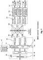
- FIG. 1illustrates a prior art MIMO system.
- FIG. 2illustrates an N-antenna Base Station communicating with a plurality of Single-antenna Client Devices.
- FIG. 3illustrates a three Antenna Base Station communicating with three Single-Antenna Client Devices
- FIG. 4illustrates training signal techniques employed in one embodiment of the invention.
- FIG. 5illustrates channel characterization data transmitted from a client device to a base station according to one embodiment of the invention.
- FIG. 6illustrates a Distributed-Input Multiple-Output (“DIMO”) downstream transmission according to one embodiment of the invention.
- DIMODistributed-Input Multiple-Output
- FIG. 7illustrates a Multiple-input Multiple Output (“MIMO”) upstream transmission according to one embodiment of the invention.
- MIMOMultiple-input Multiple Output
- FIG. 8illustrates a base station cycling through different client groups to allocate bandwidth according to one embodiment of the invention.
- FIG. 9illustrates a grouping of clients based on proximity according to one embodiment of the invention.
- FIG. 10illustrates embodiment of the invention employed within an NVIS system.
- FIG. 1shows a prior art MIMO system with transmit antennas 104 and receive antennas 105 .
- Such a systemcan achieve up to 3 ⁇ the throughput that would normally be achievable in the available channel.
- There are a number of different approaches in which to implement the details of such a MIMO systemwhich are described in published literature on the subject, and the following explanation describes one such approach.
- the channelis “characterized.” This is accomplished by initially transmitting a “training signal” from each of the transmit antennas 104 to each of the receivers 105 .
- the training signalis generated by the coding and modulation subsystem 102 , converted to analog by a D/A converter (not shown), and then converted from baseband to RF by each transmitter 103 , in succession.
- Each receive antenna 105 coupled to its RF Receiver 106receives each training signal and converts it to baseband.
- the baseband signalis converted to digital by a D/A converter (not shown), and the signal processing subsystem 107 characterizes the training signal.
- Each signal's characterizationmay include many factors including, for example, phase and amplitude relative to a reference internal to the receiver, an absolute reference, a relative reference, characteristic noise, or other factors.
- Each signal's characterizationis typically defined as a vector that characterizes phase and amplitude changes of several aspects of the signal when it is transmitted across the channel.
- the characterizationmight be a vector of the phase and amplitude offsets of several multipath images of the signal.
- OFDMorthogonal frequency division multiplexing
- the signal processing subsystem 107stores the channel characterization received by each receiving antenna 105 and corresponding receiver 106 . After all three transmit antennas 104 have completed their training signal transmissions, then the signal processing subsystem 107 will have stored three channel characterizations for each of three receiving antennas 105 , resulting in a 3 ⁇ 3 matrix 108 , designated as the channel characterization matrix, “H.” Each individual matrix element H ij is the channel characterization (which is typically a vector, as described above) of the training signal transmission of transmit antenna 104 i as received by the receive antenna 105 j.
- the signal processing subsystem 107inverts the matrix H 108 , to produce H ⁇ 1 , and awaits transmission of actual data from transmit antennas 104 .
- various prior art MIMO techniques described in available literaturecan be utilized to ensure that the H matrix 108 can be inverted.
- a payload of data to be transmittedis presented to the data Input subsystem 100 . It is then divided up into three parts by splitter 101 prior to being presented to coding and modulation subsystem 102 . For example, if the payload is the ASCII bits for “abcdef,” it might be divided up into three sub-payloads of ASCII bits for “ad,” “be,” and “cf” by Splitter 101 . Then, each of these sub-payloads is presented individually to the coding and modulation subsystem 102 .
- Each of the sub-payloadsis individually coded by using a coding system suitable for both statistical independence of each signal and error correction capability. These include, but are not limited to Reed-Solomon coding, Viterbi coding, and Turbo Codes.
- each of the three coded sub-payloadsis modulated using an appropriate modulation scheme for the channel.
- Example modulation schemesare differential phase shift key (“DPSK”) modulation, 64-QAM modulation and OFDM. It should be noted here that the diversity gains provided by MIMO allow for higher-order modulation constellations that would otherwise be feasible in a SISO (Single Input-Single Output) system utilizing the same channel.
- DPSKdifferential phase shift key
- 64-QAM modulation64-QAM modulation
- OFDMOFDM
- each of the receiving antennas 105will receive a different combination of the three transmitted signals from antennas 104 .
- Each signalis received and converted down to baseband by each RF receiver 106 , and digitized by an A/D converter (not shown). If y n is the signal received by the nth receive antenna 105 , and x n is the signal transmitted by nth transmit antenna 104 , and N is noise, this can be described by the following three equations.
- y 1x 1 H 11 +x 2 H 21 +x 3 H 31 +N
- y 2x 1 H 12 +x 2 H 22 +x 3 H 32 +N
- y 3x 1 H 13 +x 2 H 23 +x 3 H 33 +N
- the three transmitted signals x nare then demodulated, decoded, and error-corrected by signal processing subsystem 107 to recover the three bit streams that were originally separated out by splitter 101 .
- These bit streamsare combined in combiner unit 108 , and output as a single data stream from the data output 109 . Assuming the robustness of the system is able to overcome the noise impairments, the data output 109 will produce the same bit stream that was introduced to the data Input 100 .
- FIG. 2illustrates one embodiment of the invention in which a Base Station 200 is configured with a Wide Area Network interface (e.g. to the Internet through a Ti or other high speed connection) 201 and is provisioned with a number (n) of antennas 202 .
- a Base Station 200is configured with a Wide Area Network interface (e.g. to the Internet through a Ti or other high speed connection) 201 and is provisioned with a number (n) of antennas 202 .
- Client Devices 203 - 207each with a single antenna, which are served wirelessly from the Base Station 200 .
- this architecturewill apply to a large number of applications, both indoor and outdoor, where a Base Station is serving wireless clients.
- the Base Stationcould be based at a cellular phone tower, or on a television broadcast tower.
- the Base Station 200is positioned on the ground and is configured to transmit upward at HF frequencies (e.g., frequencies up to 24 MHz) to bounce signals off the ionosphere as described in co-pending application entitled SYSTEM AND METHOD FOR ENHANCING NEAR VERTICAL INCIDENCE SKYWAVE (“NVIS”) COMMUNICATION USING SPACE-TIME CODING, Ser. No. 10/817,731, Filed Apr. 20, 2004, which is assigned to the assignee of the present application and which is incorporated herein by reference.
- HF frequenciese.g., frequencies up to 24 MHz
- the Base Station 200 and Client Devices 203 - 207 set forth aboveare for the purpose of illustration only and are not required for complying with the underlying principles of the invention.
- the Base Stationmay be connected to a variety of different types of wide area networks via WAN interface 201 including application-specific wide area networks such as those used for digital video distribution.
- the Client Devicesmay be any variety of wireless data processing and/or communication devices including, but not limited to cellular phones, personal digital assistants (“PDAs”), receivers, and wireless cameras.
- PDAspersonal digital assistants
- the Base Station's n Antennas 202are separated spatially such that each is transmitting and receiving signals which are not spatially correlated, just as if the Base Station was a prior art MIMO transceiver.
- ⁇ /6i.e. 1 ⁇ 6 wavelength
- a single Base Station 200may very well have its antennas located very far apart.
- the antennasmay be 10 meters apart or more (e.g., in an NVIS implementation mentioned above). If 100 such antennas are used, the Base Station's antenna array could well occupy several square kilometers.
- one embodiment of the inventionpolarizes the signal in order to increase the effective bandwidth of the system.
- Increasing channel bandwidth through polarizationis a well known technique which has been employed by satellite television providers for years.
- Using polarizationit is possible to have multiple (e.g., three) Base Station antennas very close to each other, and still be not spatially correlated.
- conventional RF systemsusually will only benefit from the diversity of two dimensions (e.g. x and y) of polarization, the architecture described herein may further benefit from the diversity of three dimensions of polarization (x, y and z).
- FIG. 3provides additional detail of one embodiment of the Base Station 200 and Client Devices 203 - 207 shown in FIG. 2 .
- the Base Station 300is shown with only three antennas 305 and only three Client Devices 306 - 308 . It will be noted, however, that the embodiments of the invention described herein may be implemented with a virtually unlimited number of antennas 305 (i.e., limited only by available space and noise) and Client Devices 306 - 308 .
- FIG. 3is similar to the prior art MIMO architecture shown in FIG. 1 in that both have three antennas on each sides of a communication channel.
- a notable differenceis that in the prior art MIMO system the three antennas 105 on the right side of FIG. 1 are all a fixed distance from one another (e.g., integrated on a single device), and the received signals from each of the antennas 105 are processed together in the Signal Processing subsystem 107 .
- the three antennas 309 on the right side of the diagramare each coupled to a different Client Device 306 - 308 , each of which may be distributed anywhere within range of the Base Station 305 .
- FIG. 3illustrates a Distributed Input (i.e. antennas 309 ) Multiple Output (i.e. antennas 305 ) system, referred to hereinafter as a “DIMO” system.
- each DIMO Client Device 306 - 308requires only a single receiving antenna, whereas with MIMO, each Client Device requires as least as many receiving antennas as the bandwidth multiple that is hoped to be achieved. Given that there is usually a practical limit to how many antennas can be placed on a Client Device (as explained in the Background), this typically limits MIMO systems to between four to ten antennas (and 4 ⁇ to 10 ⁇ bandwidth multiple).
- each antennais equipped with a transceiver 304 and a portion of the processing power of a Coding, Modulation, and Signal Processing section 303 .
- each Client Device 306 - 308only will require one antenna 309 , so the cost for an individual user Client Device 306 - 308 will be low, and the cost of Base Station 300 can be shared among a large base of users.
- FIGS. 4 through 6An example of how a DIMO transmission from the Base Station 300 to the Client Devices 306 - 308 can be accomplished is illustrated in FIGS. 4 through 6 .
- the channelis characterized.
- a training signalis transmitted (in the embodiment herein described), one-by-one, by each of the antennas 405 .
- FIG. 4illustrates only the first training signal transmission, but with three antennas 405 there are three separate transmissions in total.
- Each training signalis generated by the Coding, Modulation, and Signal Processing subsystem 403 , converted to analog through a D/A converter, and transmitted as RF through each RF Transceiver 404 .
- Various different coding, modulation and signal processing techniquesmay be employed including, but not limited to, those described above (e.g., Reed Solomon, Viterbi coding; QAM, DPSK, QPSK modulation, . . . etc).
- Each Client Device 406 - 408receives a training signal through its antenna 409 and converts the training signal to baseband by Transceiver 410 .
- An A/D converter(not shown) converts the signal to digital where is it processed by each Coding, Modulation, and Signal Processing subsystem 411 .
- Signal characterization logic 320then characterizes the resulting signal (e.g., identifying phase and amplitude distortions as described above) and stores the characterization in memory. This characterization process is similar to that of prior art MIMO systems, with a notable difference being that the each client device only computes the characterization vector for its one antenna, rather than for n antennas.
- the Coding Modulation and Signal Processing subsystem 420 of client device 406is initialized with a known pattern of the training signal (either at the time of manufacturing, by receiving it in a transmitted message, or through another initialization process).
- Coding Modulation and Signal Processing subsystem 420uses correlation methods to find the strongest received pattern of the training signal, it stores the phase and amplitude offset, then it subtracts this pattern from the received signal.
- it finds then second strongest received pattern that correlates to the training signalit stores the phase and amplitude offset, then it subtracts this second strongest pattern from the received signal. This process continues until either some fixed number of phase and amplitude offsets are stored (e.g.
- Coding Modulation and Signal Processing subsystems for Client Devices 407 and 408implement the same processing to produce their vector elements H 21 and H 31 .
- the memory in which the characterization is storedmay be a non-volatile memory such as a Flash memory or a hard drive and/or a volatile memory such as a random access memory (e.g., SDRAM, RDAM).
- a non-volatile memorysuch as a Flash memory or a hard drive
- a volatile memorysuch as a random access memory (e.g., SDRAM, RDAM).
- different Client Devicesmay concurrently employ different types of memories to store the characterization information (e.g., PDA's may use Flash memory whereas notebook computers may use a hard drive).
- PDA'smay use Flash memory whereas notebook computers may use a hard drive).
- the underlying principles of the inventionare not limited to any particular type of storage mechanism on the various Client Devices or the Base Station.
- FIG. 4illustrates the stage after the first training signal transmission where the first row of 1 ⁇ 3 columns 413 - 415 has been stored with channel characterization information for the first of the three Base Station antennas 405 .
- the remaining two columnsare stored following the channel characterization of the next two training signal transmissions from the remaining two base station antennas.
- the three training signalsare transmitted at separate times. If the three training signal patterns are chosen such as not to be correlated to one another, they may be transmitted simultaneously, thereby reducing training time.
- each Client Device 506 - 508transmits back to the Base Station 500 the 1 ⁇ 3 column 513 - 515 of matrix H that it has stored.
- An appropriate modulation schemee.g. DPSK, 64QAM, OFDM
- adequate error correction codinge.g. Reed Solomon, Viterbi, and/or Turbo codes
- antennas 505are shown receiving the signal in FIG. 5 , it is sufficient for a single antenna and transceiver of the Base Station 500 to receive each 1 ⁇ 3 column 513 - 515 transmission.
- utilizing many or all of antennas 505 and Transceivers 504 to receive each transmissioni.e., utilizing prior art Multiple-input Single-Output (“MISO”) processing techniques in the Coding, Modulation and Signal Processing subsystem 503 ) may yield a better signal-to-noise ratio (“SNR”) than utilizing a single antenna 505 and Transceiver 504 under certain conditions.
- MISOMultiple-input Single-Output
- the Coding, Modulation and Signal Processing subsystem 503 of Base Station 500receives the 1 ⁇ 3 column 513 - 515 , from each Client Device 507 - 508 , it stores it in a 3 ⁇ 3 H matrix 516 .
- the Base Stationmay employ various different storage technologies including, but not limited to non-volatile mass storage memories (e.g., hard drives) and/or volatile memories (e.g., SDRAM) to store the matrix 516 .
- FIG. 5illustrates a stage at which the Base Station 500 has received and stored the 1 ⁇ 3 column 513 from Client Device 509 .
- the 1 ⁇ 3 columns 514 and 515may be transmitted and stored in H matrix 516 as they are received from the remaining Client Devices, until the entire H matrix 516 is stored.
- a DIMO transmission from a Base Station 600 to Client Devices 606 - 608will now be described with reference to FIG. 6 .
- each Client Device 606 - 608is an independent device, typically each device is receiving a different data transmission.
- a Base Station 600includes a Router 602 communicatively positioned between the WAN Interface 601 and the Coding, Modulation and Signal Processing subsystem 603 that sources multiple data streams (formatted into bit streams) from the WAN interface 601 and routes them as separate bit streams u 1 -u 3 intended for each Client Device 606 - 608 , respectively.
- Various well known routing techniquesmay be employed by the router 602 for this purpose.
- the three bit streams, u 1 -u 3 , shown in FIG. 6are then routed into the Coding, Modulation and Signal Processing subsystem 603 and coded into statistically distinct, error correcting streams (e.g. using Reed Solomon, Viterbi, or Turbo Codes) and modulated using an appropriate modulation scheme for the channel (such as DPSK, 64QAM or OFDM).
- error correcting streamse.g. using Reed Solomon, Viterbi, or Turbo Codes
- an appropriate modulation scheme for the channelsuch as DPSK, 64QAM or OFDM
- the embodiment illustrated in FIG. 6includes signal preceding logic 630 for uniquely coding the signals transmitted from each of the antennas 605 based on the signal characterization matrix 616 . More specifically, rather than routing each of the three coded and modulated bit streams to a separate antenna (as is done in FIG.
- the preceding logic 630multiplies the three bit streams u 1 -u 3 in FIG. 6 by the inverse of the H matrix 616 , producing three new bit streams, u′ 1 -u′ 3 .
- the three precoded bit streamsare then converted to analog by D/A converters (not shown) and transmitted as RF by Transceivers 604 and antennas 605 .
- each u icontains the data from one of the three bit streams routed by the Router 602 , and each such bit stream is intended for one of the three Client Devices 606 - 608 .
- each u iis received at each Client Device antenna 609 (plus whatever noise N there is in the channel).
- the output of each of the three antennas 605is a function of u i and the H matrix that characterizes the channel for each Client Device.
- each antenna 609receives u i already separated from the other u n-1 bit streams intended for the other antennas 609 .
- Each Transceiver 610converts each received signal to baseband, where it is digitized by an A/D converter (now shown), and each Coding, Modulation and Signal Processing subsystem 611 , demodulates and decodes the x i bit stream intended for it, and sends its bit stream to a Data Interface 612 to be used by the Client Device (e.g., by an application on the client device).
- the embodiments of the invention described hereinmay be implemented using a variety of different coding and modulation schemes.
- the techniques described hereinmay be employed to characterize each individual sub-band.
- the underlying principles of the inventionare not limited to any particular modulation scheme.
- the channel characterization matrix 616 at the Base Stationis continually updated.
- the Base Station 600periodically (e.g., every 250 milliseconds) sends out a new training signal to each Client Device, and each Client Device continually transmits its channel characterization vector back to the Base Station 600 to ensure that the channel characterization remains accurate (e.g. if the environment changes so as to affect the channel or if a Client Device moves).
- the training signalis interleaved within the actual data signal sent to each client device.
- the channel characterization matrix 616may be updated continuously as the Base Station actively communicates with each Client Device, thereby maintaining an accurate channel characterization as the Client Devices move from one location to the next or if the environment changes so as to affect the channel.
- One embodiment of the invention illustrated in FIG. 7employs MIMO techniques to improve the upstream communication channel (i.e., the channel from the Client Devices 706 - 708 to the Base Station 700 ).
- the channel from each of the Client Devicesis continually analyzed and characterized by upstream channel characterization logic 741 within the Base Station. More specifically, each of the Client Devices 706 - 708 transmits a training signal to the Base Station 700 which the channel characterization logic 741 analyzes (e.g., as in a typical MIMO system) to generate an N ⁇ M channel characterization matrix 741 , where N is the number of Client Devices and M is the number of antennas employed by the Base Station.
- Nis the number of Client Devices
- Mis the number of antennas employed by the Base Station.
- the MIMO upstream transmission illustrated in FIG. 7may be used by the Client Devices both for transmitting data back to the Base Station 700 , and for transmitting channel characterization vectors back to the Base Station 700 as illustrated in FIG. 5 . But unlike the embodiment illustrated in FIG. 5 in which each Client Device's channel characterization vector is transmitted at a separate time, the method shown in FIG. 7 allows for the simultaneous transmission of channel characterization vectors from multiple Client Devices back to the Base Station 700 , thereby dramatically reducing the channel characterization vectors' impact on return channel throughput.
- each signal's characterizationmay include many factors including, for example, phase and amplitude relative to a reference internal to the receiver, an absolute reference, a relative reference, characteristic noise, or other factors.
- the characterizationmight be a vector of the phase and amplitude offsets of several multipath images of the signal.
- QAMquadrature amplitude modulation
- OFDMorthogonal frequency division multiplexing
- the training signalmay be generated by each Client Device's coding and modulation subsystem 711 , converted to analog by a D/A converter (not shown), and then converted from baseband to RF by each Client Device's transmitter 709 .
- Client Devicesin order to ensure that the training signals are synchronized, Client Devices only transmit training signals when requested by the Base Station (e.g., in a round robin manner).
- training signalsmay be interleaved within or transmitted concurrently with the actual data signal sent from each client device.
- the training signalsmay be continuously transmitted and analyzed by the upstream channel characterization logic 741 , thereby ensuring that the channel characterization matrix 741 remains up-to-date.
- the total channel bandwidth supported by the foregoing embodiments of the inventionmay be defined as min (N, M) where N is the number of Client Devices and M is the number of Base Station antennas. That is, the capacity is limited by the number of antennas on either the Base Station side or the Client side.
- one embodiment of the inventionemploys synchronization techniques to ensure that no more than min (N, M) antennas are transmitting/receiving at a given time.
- the number of antennas 705 on the Base Station 700will be less than the number of Client Devices 706 - 708 .
- An exemplary scenariois illustrated in FIG. 8 which shows five Client Devices 804 - 808 communicating with a base station having three antennas 802 .
- the Base Station 800selects the two Client Devices 807 , 808 which were not included in the first group. In addition, because an extra antenna is available, the Base Station 800 selects an additional client device 806 included in the first group. In one embodiment, the Base Station 800 cycles between groups of clients in this manner such that each client is effectively allocated the same amount of bandwidth over time. For example, to allocate bandwidth evenly, the Base Station may subsequently select any combination of three Client Devices which excludes Client Device 806 (i.e., because Client Device 806 was engaged in communication with the Base Station for the first two cycles).
- the Base Stationmay employ the foregoing techniques to transmit training signals to each of the Client Devices and receive training signals and signal characterization data from each of the Client Devices.
- Client Devices or groups of client devicesmay be allocated different levels of bandwidth. For example, Client Devices may be prioritized such that relatively higher priority Client Devices may be guaranteed more communication cycles (i.e., more bandwidth) than relatively lower priority client devices.
- the “priority” of a Client Devicemay be selected based on a number of variables including, for example, the designated level of a user's subscription to the wireless service (e.g., user's may be willing to pay more for additional bandwidth) and/or the type of data being communicated to/from the Client Device (e.g., real-time communication such as telephony audio and video may take priority over non-real time communication such as email).
- the Base Stationdynamically allocates bandwidth based on the Current Load required by each Client Device. For example, if Client Device 804 is streaming live video and the other devices 805 - 808 are performing non-real time functions such as email, then the Base Station 800 may allocate relatively more bandwidth to this client 804 . It should be noted, however, that the underlying principles of the invention are not limited to any particular bandwidth allocation technique.
- two Client Devices 907 , 908may be so close in proximity, that the channel characterization for the clients is effectively the same.
- the Base Stationwill receive and store effectively equivalent channel characterization vectors for the two Client Devices 907 , 908 and therefore will not be able to create unique, spatially distributed signals for each Client Device. Accordingly, in one embodiment, the Base Station will ensure that any two or more Client Devices which are in close proximity to one another are allocated to different groups. In FIG.
- the Base Station 900first communicates with a first group 910 of Client Devices 904 , 905 and 908 ; and then with a second group 911 of Client Devices 905 , 906 , 907 , ensuring that Client Devices 907 and 908 are in different groups.
- the Base Station 900communicates with both Client Devices 907 and 908 concurrently, but multiplexes the communication channel using known channel multiplexing techniques.
- the Base Stationmay employ time division multiplexing (“TDM”), frequency division multiplexing (“FDM”) or code division multiple access (“CDMA”) techniques to divide the single, spatially-correlated signal between Client Devices 907 and 908 .
- TDMtime division multiplexing
- FDMfrequency division multiplexing
- CDMAcode division multiple access
- each Client Device described aboveis equipped with a single antenna
- the underlying principles of the inventionmay be employed using Client Devices with multiple antennas to increase throughput.
- a client with 2 antennaswill realize a 2 ⁇ increase in throughput
- a client with 3 antennaswill realize a 3 ⁇ increase in throughput, and so on (i.e., assuming that the spatial and angular separation between the antennas is sufficient).
- the Base Stationmay apply the same general rules when cycling through Client Devices with multiple antennas. For example, it may treat each antenna as a separate client and allocate bandwidth to that “client” as it would any other client (e.g., ensuring that each client is provided with an adequate or equivalent period of communication).
- one embodiment of the inventionemploys the DIMO and/or MIMO signal transmission techniques described above to increase the signal-to-noise ratio and transmission bandwidth within a Near Vertical Incidence Skywave (“NVIS”) system.
- NVISNear Vertical Incidence Skywave
- a first NVIS station 1001 equipped with a matrix of N antennas 1002is configured to communicate with M client devices 1004 .
- the NVIS antennas 1002 and antennas of the various client devices 1004transmit signals upward to within about 15 degrees of vertical in order to achieve the desired NVIS and minimize ground wave interference effects.
- the antennas 1002 and client devices 1004support multiple independent data streams 1006 using the various DIMO and MIMO techniques described above at a designated frequency within the NVIS spectrum (e.g., at a carrier frequency at or below 23 MHz, but typically below 10 MHz), thereby significantly increasing the bandwidth at the designated frequency (i.e., by a factor proportional to the number of statistically independent data streams).
- the NVIS antennas serving a given stationmay be physically very far apart from each other. Given the long wavelengths below 10 MHz and the long distance traveled for the signals (as much as 300 miles round trip), physical separation of the antennas by 100s of yards, and even miles, can provide advantages in diversity. In such situations, the individual antenna signals may be brought back to a centralized location to be processed using conventional wired or wireless communications systems. Alternatively, each antenna can have a local facility to process its signals, then use conventional wired or wireless communications systems to communicate the data back to a centralized location. In one embodiment of the invention, NVIS Station 1001 has a broadband link 1015 to the Internet 1010 (or other wide area network), thereby providing the client devices 1003 with remote, high speed, wireless network access.
- the Internet 1010or other wide area network
- Embodiments of the inventionmay include various steps as set forth above.
- the stepsmay be embodied in machine-executable instructions which cause a general-purpose or special-purpose processor to perform certain steps.
- the various components within the Base Stations and Client Devices described abovemay be implemented as software executed on a general purpose or special purpose processor.
- various well known personal computer componentssuch as computer memory, hard drive, input devices, . . . etc, have been left out of the figures.
- the various functional modules illustrated herein and the associated stepsmay be performed by specific hardware components that contain hardwired logic for performing the steps, such as an application-specific integrated circuit (“ASIC”) or by any combination of programmed computer components and custom hardware components.
- ASICapplication-specific integrated circuit
- certain modulessuch as the Coding, Modulation and Signal Processing Logic 903 described above may be implemented on a programmable digital signal processor (“DSP”) (or group of DSPs) such as a DSP using a Texas Instruments' TMS320x architecture (e.g., a TMS320C6000, TMS320C5000, . . . etc).
- DSPprogrammable digital signal processor
- the DSP in this embodimentmay be embedded within an add-on card to a personal computer such as, for example, a PCI card.
- a variety of different DSP architecturesmay be used while still complying with the underlying principles of the invention.
- Elements of the present inventionmay also be provided as a machine-readable medium for storing the machine-executable instructions.
- the machine-readable mediummay include, but is not limited to, flash memory, optical disks, CD-ROMs, DVD ROMs, RAMs, EPROMs, EEPROMs, magnetic or optical cards, propagation media or other type of machine-readable media suitable for storing electronic instructions.
- the present inventionmay be downloaded as a computer program which may be transferred from a remote computer (e.g., a server) to a requesting computer (e.g., a client) by way of data signals embodied in a carrier wave or other propagation medium via a communication link (e.g., a modem or network connection).
Landscapes
- Engineering & Computer Science (AREA)
- Computer Networks & Wireless Communication (AREA)
- Signal Processing (AREA)
- Power Engineering (AREA)
- Mobile Radio Communication Systems (AREA)
- Radio Transmission System (AREA)
- Cable Transmission Systems, Equalization Of Radio And Reduction Of Echo (AREA)
Abstract
Description
y1=x1H11+x2H21+x3H31+N
y2=x1H12+x2H22+x3H32+N
y3=x1H13+x2H23+x3H33+N
x1=y1H−111+y2H−112+y3H−113
x2=y1H−121+y2H−122+y3H−123
x3=y1H−131+y2H−132+y3H−133
v1=u1H−111+u2H−112+u3H−113v2=u1H−121+u2H−122+u3H−123
v3=u1H−131+u2H−132+u3H−133
Claims (25)
Priority Applications (28)
| Application Number | Priority Date | Filing Date | Title |
|---|---|---|---|
| US10/902,978US7418053B2 (en) | 2004-07-30 | 2004-07-30 | System and method for distributed input-distributed output wireless communications |
| AU2005203336AAU2005203336B2 (en) | 2004-07-30 | 2005-07-29 | System and method for distributed input distributed output wireless communications |
| EP10184659.0AEP2278764B1 (en) | 2004-07-30 | 2005-07-29 | System and method for distributed input distributed output wireless communications |
| TW094125985ATWI372541B (en) | 2004-07-30 | 2005-07-29 | System and method for distributed input distributed output wireless communications |
| FIEP05254757.7TFI1622329T3 (en) | 2004-07-30 | 2005-07-29 | System and method for distributed input-distributed output wireless communications |
| CA2514383ACA2514383C (en) | 2004-07-30 | 2005-07-29 | System and method for distributed input distributed output wireless communications |
| FIEP10184659.0TFI2278764T3 (en) | 2004-07-30 | 2005-07-29 | System and method for distributed input distributed output wireless communications |
| EP05254757.7AEP1622329B1 (en) | 2004-07-30 | 2005-07-29 | System and method for distributed input-distributed output wireless communications |
| CA2856772ACA2856772C (en) | 2004-07-30 | 2005-07-29 | System and method for distributed input distributed output wireless communications |
| KR1020050070079AKR101170336B1 (en) | 2004-07-30 | 2005-07-30 | System and method for distributed input distributed output wireless communications |
| JP2005223345AJP2006081162A (en) | 2004-07-30 | 2005-08-01 | System and method for input-distributed, output-distributed type wireless communications |
| CN2005100886761ACN1734972B (en) | 2004-07-30 | 2005-08-01 | System and method for distributed input distributed output wireless communications |
| US11/256,478US7711030B2 (en) | 2004-07-30 | 2005-10-21 | System and method for spatial-multiplexed tropospheric scatter communications |
| HK06108125.5AHK1087850B (en) | 2004-07-30 | 2006-07-20 | System and method for distributed input distributed output wireless communications |
| US11/894,540US7636381B2 (en) | 2004-07-30 | 2007-08-20 | System and method for distributed input-distributed output wireless communications |
| US11/894,362US7633994B2 (en) | 2004-07-30 | 2007-08-20 | System and method for distributed input-distributed output wireless communications |
| US11/894,394US7599420B2 (en) | 2004-07-30 | 2007-08-20 | System and method for distributed input distributed output wireless communications |
| US12/637,643US8428162B2 (en) | 2004-07-30 | 2009-12-14 | System and method for distributed input distributed output wireless communications |
| US15/340,914US10985811B2 (en) | 2004-04-02 | 2016-11-01 | System and method for distributed antenna wireless communications |
| US15/616,817US10243623B2 (en) | 2004-07-30 | 2017-06-07 | Systems and methods to enhance spatial diversity in distributed-input distributed-output wireless systems |
| US16/253,028US10727907B2 (en) | 2004-07-30 | 2019-01-21 | Systems and methods to enhance spatial diversity in distributed input distributed output wireless systems |
| US17/234,699US11196467B2 (en) | 2004-04-02 | 2021-04-19 | System and method for distributed antenna wireless communications |
| US17/308,031US11190246B2 (en) | 2004-04-02 | 2021-05-04 | System and method for distributed antenna wireless communications |
| US17/317,856US11190247B2 (en) | 2004-04-02 | 2021-05-11 | System and method for distributed antenna wireless communications |
| US17/541,809US11394436B2 (en) | 2004-04-02 | 2021-12-03 | System and method for distributed antenna wireless communications |
| US17/586,765US11451275B2 (en) | 2004-04-02 | 2022-01-27 | System and method for distributed antenna wireless communications |
| US17/948,193US11646773B2 (en) | 2004-04-02 | 2022-09-19 | System and method for distributed antenna wireless communications |
| US18/144,838US11923931B2 (en) | 2004-04-02 | 2023-05-08 | System and method for distributed antenna wireless communications |
Applications Claiming Priority (1)
| Application Number | Priority Date | Filing Date | Title |
|---|---|---|---|
| US10/902,978US7418053B2 (en) | 2004-07-30 | 2004-07-30 | System and method for distributed input-distributed output wireless communications |
Related Child Applications (4)
| Application Number | Title | Priority Date | Filing Date |
|---|---|---|---|
| US11/256,478Continuation-In-PartUS7711030B2 (en) | 2004-04-02 | 2005-10-21 | System and method for spatial-multiplexed tropospheric scatter communications |
| US11/894,394Continuation-In-PartUS7599420B2 (en) | 2004-04-02 | 2007-08-20 | System and method for distributed input distributed output wireless communications |
| US11/894,540Continuation-In-PartUS7636381B2 (en) | 2004-04-02 | 2007-08-20 | System and method for distributed input-distributed output wireless communications |
| US11/894,362Continuation-In-PartUS7633994B2 (en) | 2004-04-02 | 2007-08-20 | System and method for distributed input-distributed output wireless communications |
Publications (2)
| Publication Number | Publication Date |
|---|---|
| US20060023803A1 US20060023803A1 (en) | 2006-02-02 |
| US7418053B2true US7418053B2 (en) | 2008-08-26 |
Family
ID=34941850
Family Applications (1)
| Application Number | Title | Priority Date | Filing Date |
|---|---|---|---|
| US10/902,978Active2026-08-03US7418053B2 (en) | 2004-04-02 | 2004-07-30 | System and method for distributed input-distributed output wireless communications |
Country Status (9)
| Country | Link |
|---|---|
| US (1) | US7418053B2 (en) |
| EP (2) | EP2278764B1 (en) |
| JP (1) | JP2006081162A (en) |
| KR (1) | KR101170336B1 (en) |
| CN (1) | CN1734972B (en) |
| AU (1) | AU2005203336B2 (en) |
| CA (2) | CA2856772C (en) |
| FI (2) | FI1622329T3 (en) |
| TW (1) | TWI372541B (en) |
Cited By (53)
| Publication number | Priority date | Publication date | Assignee | Title |
|---|---|---|---|---|
| US20050220207A1 (en)* | 2004-04-02 | 2005-10-06 | Perlman Stephen G | System and method for enhancing near vertical incidence skywave ("NVIS") communication using space-time coding |
| US20060217070A1 (en)* | 2005-03-11 | 2006-09-28 | Atc Technologies, Llc | Modification of transmission values to compensate for interference in a satellite down-link communications |
| US20070025464A1 (en)* | 2004-07-30 | 2007-02-01 | Perlman Stephen G | System and method for spatial-multiplexed tropospheric scatter communications |
| US20070263745A1 (en)* | 2006-05-15 | 2007-11-15 | Hitachi, Ltd. | MIMO wireless data communication system, MIMO wireless data communication method and MIMO wireless data communication apparatus |
| US20080080631A1 (en)* | 2004-07-30 | 2008-04-03 | Antonio Forenza | System and method for ditributed input-distributed output wireless communications |
| US20080118004A1 (en)* | 2004-07-30 | 2008-05-22 | Antonio Forenza | System and method for distributed input-distributed output wireless communications |
| US20080130790A1 (en)* | 2004-07-30 | 2008-06-05 | Antionio Forenza | System and method for distributed input distributed output wireless communications |
| US20090067402A1 (en)* | 2007-08-20 | 2009-03-12 | Antonio Forenza | System and Method For Distributed Input-Distributed Output Wireless Communications |
| US20090318091A1 (en)* | 2008-06-18 | 2009-12-24 | Mediatek Inc. | Method and system for beamforming training and communications apparatuses utilizing the same |
| US20100002789A1 (en)* | 2008-07-07 | 2010-01-07 | Karabinis Peter D | Increased capacity communications systems, methods and/or devices |
| US20100246496A1 (en)* | 2007-12-04 | 2010-09-30 | Hiroyuki Yurugi | Wireless communication system having mimo communication capability and having multiple receiving antennas to be selected |
| US20100316163A1 (en)* | 2004-04-02 | 2010-12-16 | Antonio Forenza | System and method for DIDO precoding interpolation in multicarrier systems |
| US20110002410A1 (en)* | 2004-04-02 | 2011-01-06 | Antonio Forenza | System and method for power control and antenna grouping in a distributed-input-distributed-output (DIDO) network |
| US20110002371A1 (en)* | 2004-04-02 | 2011-01-06 | Antonio Forenza | System and method for adjusting DIDO interference cancellation based on signal strength measurements |
| US20110003608A1 (en)* | 2004-04-02 | 2011-01-06 | Antonio Forenza | System and method for managing handoff of a client between different distributed-input-distributed-output (DIDO) networks based on detected velocity of the client |
| US20110002411A1 (en)* | 2004-04-02 | 2011-01-06 | Antonio Forenza | System and method for link adaptation in DIDO multicarrier systems |
| US20110003606A1 (en)* | 2004-04-02 | 2011-01-06 | Antonio Forenza | System and method for managing inter-cluster handoff of clients which traverse multiple DIDO clusters |
| US20110044193A1 (en)* | 2004-04-02 | 2011-02-24 | Antonio Forenza | Systems and methods to coordinate transmissions in distributed wireless systems via user clustering |
| US20110103437A1 (en)* | 2005-06-22 | 2011-05-05 | EICES Research Inc. | Private, convert and/or cognitive communications systems and/or methods based upon pseudo-randomly generated communications alphabets |
| US20110123028A1 (en)* | 2005-06-22 | 2011-05-26 | Eices Research, Inc. | Systems and/or methods of increased privacy wireless communications |
| US20110158340A1 (en)* | 2009-12-28 | 2011-06-30 | Qualcomm Incorporated | Virtual antenna array for wireless devices |
| US20110235728A1 (en)* | 2010-03-29 | 2011-09-29 | Eices Research, Inc. | Increased capacity communications for ofdm-based wireless communications systems/methods/devices |
| WO2013040089A2 (en) | 2011-09-14 | 2013-03-21 | Rearden, Llc | Systems and methods to exploit areas of coherence in wireless systems |
| US8654815B1 (en) | 2004-04-02 | 2014-02-18 | Rearden, Llc | System and method for distributed antenna wireless communications |
| WO2014055294A1 (en) | 2012-10-02 | 2014-04-10 | Rearden, Llc | Systems and methods for wireless backhaul in distributed-input distributed-output wireless systems |
| US8989155B2 (en) | 2007-08-20 | 2015-03-24 | Rearden, Llc | Systems and methods for wireless backhaul in distributed-input distributed-output wireless systems |
| US9312929B2 (en) | 2004-04-02 | 2016-04-12 | Rearden, Llc | System and methods to compensate for Doppler effects in multi-user (MU) multiple antenna systems (MAS) |
| US9374746B1 (en) | 2008-07-07 | 2016-06-21 | Odyssey Wireless, Inc. | Systems/methods of spatial multiplexing |
| US9685997B2 (en) | 2007-08-20 | 2017-06-20 | Rearden, Llc | Systems and methods to enhance spatial diversity in distributed-input distributed-output wireless systems |
| US9806790B2 (en) | 2010-03-29 | 2017-10-31 | Odyssey Wireless, Inc. | Systems/methods of spectrally efficient communications |
| US9923657B2 (en) | 2013-03-12 | 2018-03-20 | Rearden, Llc | Systems and methods for exploiting inter-cell multiplexing gain in wireless cellular systems via distributed input distributed output technology |
| US9973246B2 (en) | 2013-03-12 | 2018-05-15 | Rearden, Llc | Systems and methods for exploiting inter-cell multiplexing gain in wireless cellular systems via distributed input distributed output technology |
| US10110357B2 (en) | 2016-11-03 | 2018-10-23 | Industrial Technology Research Institute | Cooperative communication method and system |
| US10164698B2 (en) | 2013-03-12 | 2018-12-25 | Rearden, Llc | Systems and methods for exploiting inter-cell multiplexing gain in wireless cellular systems via distributed input distributed output technology |
| US10194346B2 (en) | 2012-11-26 | 2019-01-29 | Rearden, Llc | Systems and methods for exploiting inter-cell multiplexing gain in wireless cellular systems via distributed input distributed output technology |
| US10200094B2 (en) | 2004-04-02 | 2019-02-05 | Rearden, Llc | Interference management, handoff, power control and link adaptation in distributed-input distributed-output (DIDO) communication systems |
| US10277290B2 (en) | 2004-04-02 | 2019-04-30 | Rearden, Llc | Systems and methods to exploit areas of coherence in wireless systems |
| US10425134B2 (en) | 2004-04-02 | 2019-09-24 | Rearden, Llc | System and methods for planned evolution and obsolescence of multiuser spectrum |
| USRE47633E1 (en) | 2005-06-22 | 2019-10-01 | Odyssey Wireless Inc. | Systems/methods of conducting a financial transaction using a smartphone |
| US10470180B2 (en) | 2018-01-24 | 2019-11-05 | Shure Acquisition Holdings, Inc. | Wireless microphone system |
| US10488535B2 (en) | 2013-03-12 | 2019-11-26 | Rearden, Llc | Apparatus and method for capturing still images and video using diffraction coded imaging techniques |
| US10547358B2 (en) | 2013-03-15 | 2020-01-28 | Rearden, Llc | Systems and methods for radio frequency calibration exploiting channel reciprocity in distributed input distributed output wireless communications |
| US10749582B2 (en) | 2004-04-02 | 2020-08-18 | Rearden, Llc | Systems and methods to coordinate transmissions in distributed wireless systems via user clustering |
| US10985811B2 (en) | 2004-04-02 | 2021-04-20 | Rearden, Llc | System and method for distributed antenna wireless communications |
| US11050468B2 (en) | 2014-04-16 | 2021-06-29 | Rearden, Llc | Systems and methods for mitigating interference within actively used spectrum |
| US11190947B2 (en) | 2014-04-16 | 2021-11-30 | Rearden, Llc | Systems and methods for concurrent spectrum usage within actively used spectrum |
| US11189917B2 (en) | 2014-04-16 | 2021-11-30 | Rearden, Llc | Systems and methods for distributing radioheads |
| US11290162B2 (en) | 2014-04-16 | 2022-03-29 | Rearden, Llc | Systems and methods for mitigating interference within actively used spectrum |
| US11309943B2 (en) | 2004-04-02 | 2022-04-19 | Rearden, Llc | System and methods for planned evolution and obsolescence of multiuser spectrum |
| US11394436B2 (en) | 2004-04-02 | 2022-07-19 | Rearden, Llc | System and method for distributed antenna wireless communications |
| US11451275B2 (en) | 2004-04-02 | 2022-09-20 | Rearden, Llc | System and method for distributed antenna wireless communications |
| EP4340305A2 (en) | 2014-02-07 | 2024-03-20 | Rearden, LLC | Systems and methods for mapping virtual radio instances into physical volumes of coherence in distributed antenna systems |
| US12425093B2 (en) | 2022-09-19 | 2025-09-23 | Electronics And Telecommunications Research Institute | Method and apparatus for signal transmission and reception in communication system |
Families Citing this family (65)
| Publication number | Priority date | Publication date | Assignee | Title |
|---|---|---|---|---|
| US8670390B2 (en) | 2000-11-22 | 2014-03-11 | Genghiscomm Holdings, LLC | Cooperative beam-forming in wireless networks |
| US10931338B2 (en) | 2001-04-26 | 2021-02-23 | Genghiscomm Holdings, LLC | Coordinated multipoint systems |
| US10355720B2 (en) | 2001-04-26 | 2019-07-16 | Genghiscomm Holdings, LLC | Distributed software-defined radio |
| US9819449B2 (en) | 2002-05-14 | 2017-11-14 | Genghiscomm Holdings, LLC | Cooperative subspace demultiplexing in content delivery networks |
| US10142082B1 (en) | 2002-05-14 | 2018-11-27 | Genghiscomm Holdings, LLC | Pre-coding in OFDM |
| US10644916B1 (en) | 2002-05-14 | 2020-05-05 | Genghiscomm Holdings, LLC | Spreading and precoding in OFDM |
| US9628231B2 (en) | 2002-05-14 | 2017-04-18 | Genghiscomm Holdings, LLC | Spreading and precoding in OFDM |
| US10200227B2 (en) | 2002-05-14 | 2019-02-05 | Genghiscomm Holdings, LLC | Pre-coding in multi-user MIMO |
| JP2007518090A (en)* | 2004-01-07 | 2007-07-05 | コーニンクレッカ フィリップス エレクトロニクス エヌ ヴィ | AMR sensor element for angle measurement |
| US11552737B1 (en) | 2004-08-02 | 2023-01-10 | Genghiscomm Holdings, LLC | Cooperative MIMO |
| US11381285B1 (en) | 2004-08-02 | 2022-07-05 | Genghiscomm Holdings, LLC | Transmit pre-coding |
| US11184037B1 (en) | 2004-08-02 | 2021-11-23 | Genghiscomm Holdings, LLC | Demodulating and decoding carrier interferometry signals |
| EP1856827B1 (en)* | 2005-03-01 | 2009-04-29 | Elektrobit System Test OY | A method, device arrangement, transmitter unit and receiver unit for generating data characterising mimo environment |
| US8469122B2 (en)* | 2005-05-24 | 2013-06-25 | Rearden, Llc | System and method for powering vehicle using radio frequency signals and feedback |
| US8307922B2 (en)* | 2005-05-24 | 2012-11-13 | Rearden, Llc | System and method for powering an aircraft using radio frequency signals and feedback |
| US7970345B2 (en)* | 2005-06-22 | 2011-06-28 | Atc Technologies, Llc | Systems and methods of waveform and/or information splitting for wireless transmission of information to one or more radioterminals over a plurality of transmission paths and/or system elements |
| US20070076649A1 (en)* | 2005-09-30 | 2007-04-05 | Intel Corporation | Techniques for heterogeneous radio cooperation |
| WO2007064249A1 (en)* | 2005-11-29 | 2007-06-07 | Telefonaktiebolaget Lm Ericsson (Publ) | Scheduling in a wireless multi-hop relay network |
| US7489670B2 (en)* | 2005-12-27 | 2009-02-10 | Celeno Communications Ltd. | Device, system and method of uplink/downlink communication in wireless network |
| US20070153760A1 (en) | 2005-12-29 | 2007-07-05 | Nir Shapira | Method, apparatus and system of spatial division multiple access communication in a wireless local area network |
| US7751353B2 (en)* | 2005-12-29 | 2010-07-06 | Celeno Communications (Israel) Ltd. | Device, system and method of securing wireless communication |
| US9071435B2 (en) | 2005-12-29 | 2015-06-30 | Celeno Communications Ltd. | System and method for tuning transmission parameters in multi-user multiple-input-multiple-output systems with aged and noisy channel estimation |
| US20070153754A1 (en)* | 2005-12-29 | 2007-07-05 | Nir Shapira | Method, apparatus and system of spatial division multiple access communication in a wireless local area network |
| US7570624B2 (en) | 2005-12-29 | 2009-08-04 | Celeno Communications (Israel) Ltd. | Device, system and method of uplink/downlink communication in wireless network |
| US7656965B2 (en)* | 2005-12-29 | 2010-02-02 | Celeno Communications (Israel) Ltd. | Method of secure WLAN communication |
| US7672400B2 (en)* | 2005-12-29 | 2010-03-02 | Celeno Communications (Israel) Ltd. | Method of secure WLAN communication |
| KR20070095138A (en)* | 2006-03-20 | 2007-09-28 | 삼성전자주식회사 | Apparatus and method for receiving uplink signal using sequential interference cancellation in orthogonal division multiple access system |
| KR20120123156A (en) | 2006-10-02 | 2012-11-07 | 인터디지탈 테크날러지 코포레이션 | Method and apparatus for encoding channel quality indicator and precoding control information bits |
| FI20065841A0 (en)* | 2006-12-21 | 2006-12-21 | Nokia Corp | Communication method and systems |
| CN101636994B (en) | 2007-03-21 | 2014-02-19 | 交互数字技术公司 | MIMO wireless communication method and device based on dedicated reference signal mode transmission and decoding resource block structure |
| FR2915333B1 (en)* | 2007-04-19 | 2009-07-10 | Inst Nat Sciences Appliq | METHOD OF TRANSMITTING A TRANSMITTER COMPRISING A SINGLE ANTENNA FROM A DATA SET TO A RECEIVER COMPRISING ANTENNAS |
| US20080317145A1 (en)* | 2007-06-25 | 2008-12-25 | Bruno Clerckx | Multiple input multiple output communication system and a method of adaptively generating codebook |
| US8010116B2 (en)* | 2007-06-26 | 2011-08-30 | Lgc Wireless, Inc. | Distributed antenna communications system |
| CN101370241B (en)* | 2007-08-19 | 2015-01-14 | 上海贝尔股份有限公司 | Method and device for eliminating interference between received signal of multiple mobile stations |
| KR101598324B1 (en)* | 2007-08-20 | 2016-02-26 | 리어덴 엘엘씨 | System and method for distributed input distributed output wireless communications |
| WO2009026741A1 (en)* | 2007-08-29 | 2009-03-05 | Alcatel Shanghai Bell Company, Ltd. | Method and device for distributed precoding |
| US20090129513A1 (en)* | 2007-11-16 | 2009-05-21 | Nokia Corporation | Apparatus, methods, and computer program products providing partial MIMO reception and decoding |
| EP2219309B1 (en)* | 2007-12-05 | 2016-01-06 | Fujitsu Limited | Transmitter, method for controlling transmission, and communication device |
| WO2009088151A1 (en)* | 2008-01-05 | 2009-07-16 | Persbro Corporation | Private multimedia contents broadcasting equipment which uses ism radio frequency band or u-nii 5 radio frequency band, private multimedia contents broadcasting system and method thereof |
| KR100899332B1 (en)* | 2008-01-05 | 2009-05-27 | 주식회사 퍼스브로 | Personal multimedia content broadcasting device using ISM radio frequency band or unlicensed 5 GHz radio frequency band, personal multimedia content broadcasting system using same and broadcasting method thereof |
| US9030948B2 (en) | 2008-03-30 | 2015-05-12 | Qualcomm Incorporated | Encoding and decoding of control information for wireless communication |
| CN101557246B (en)* | 2008-04-07 | 2012-10-03 | 中国移动通信集团公司 | Uplink power control method and device |
| US8848816B2 (en)* | 2008-05-21 | 2014-09-30 | Qualcomm Incorporated | Method and apparatus for determining the spatial channels in a spatial division multiple access (SDMA)-based wireless communication system |
| US8634405B2 (en)* | 2008-09-08 | 2014-01-21 | The Trustees Of Princeton University | System and method for synchronizing phases and frequencies of devices in multi-user, wireless communications systems |
| US8494031B2 (en)* | 2009-02-27 | 2013-07-23 | Qualcomm Incorporated | Protocol operation and message design for SDMA data transmission to a plurality of stations |
| CN101867965B (en)* | 2009-04-15 | 2014-01-01 | 中兴通讯股份有限公司 | Method and device for user terminal pairing in multi-user multiple-input multiple-output |
| EP2471200A4 (en) | 2009-12-10 | 2012-10-17 | Lg Electronics Inc | Method and apparatus of transmitting training signal in wireless local area network system |
| JP2012049923A (en)* | 2010-08-27 | 2012-03-08 | Kyocera Corp | Radio communication equipment, communication system, and control method |
| KR101839808B1 (en)* | 2011-08-24 | 2018-04-26 | 삼성전자주식회사 | Mobile Terminal and Communication Method, Base Station Control Apparatus and Method, and Multi-Point Transmission System and Method using the Same |
| CN103378897B (en)* | 2012-04-23 | 2017-12-22 | 中兴通讯股份有限公司 | Realize the method and device of CMMB diversity reception |
| SG11201407160YA (en)* | 2012-05-18 | 2014-11-27 | Rearden Llc | Systems and methods to enhance spatial diversity in distributed input distributed output wireless systems |
| TWI467936B (en) | 2012-11-22 | 2015-01-01 | Ind Tech Res Inst | Method and apparatus for interference suppression in radio-over-fiber communication systems |
| US12224860B1 (en) | 2014-01-30 | 2025-02-11 | Genghiscomm Holdings, LLC | Linear coding in decentralized networks |
| JP2017079392A (en)* | 2015-10-20 | 2017-04-27 | 株式会社レイトロン | Radio photographing system and photographing device |
| WO2018156825A1 (en)* | 2017-02-24 | 2018-08-30 | AMI Research & Development, LLC | Directional mimo antenna |
| US10243773B1 (en) | 2017-06-30 | 2019-03-26 | Genghiscomm Holdings, LLC | Efficient peak-to-average-power reduction for OFDM and MIMO-OFDM |
| US10637705B1 (en) | 2017-05-25 | 2020-04-28 | Genghiscomm Holdings, LLC | Peak-to-average-power reduction for OFDM multiple access |
| CN111971912B (en)* | 2018-03-29 | 2022-11-01 | 瑞典爱立信有限公司 | Identification of underperforming radio branches |
| US11343823B2 (en) | 2020-08-16 | 2022-05-24 | Tybalt, Llc | Orthogonal multiple access and non-orthogonal multiple access |
| US12206535B1 (en) | 2018-06-17 | 2025-01-21 | Tybalt, Llc | Artificial neural networks in wireless communication systems |
| US10797746B2 (en)* | 2018-11-16 | 2020-10-06 | Ossia Inc. | Coded antenna array |
| WO2020154550A1 (en) | 2019-01-25 | 2020-07-30 | Genghiscomm Holdings, LLC | Orthogonal multiple access and non-orthogonal multiple access |
| WO2020242898A1 (en) | 2019-05-26 | 2020-12-03 | Genghiscomm Holdings, LLC | Non-orthogonal multiple access |
| US10965352B1 (en) | 2019-09-24 | 2021-03-30 | Rampart Communications, Inc. | Communication system and methods using very large multiple-in multiple-out (MIMO) antenna systems with extremely large class of fast unitary transformations |
| CN111541046B (en)* | 2020-05-08 | 2022-02-11 | 中国联合网络通信集团有限公司 | Luneberg lens antenna and base station |
Citations (21)
| Publication number | Priority date | Publication date | Assignee | Title |
|---|---|---|---|---|
| US4564935A (en) | 1984-01-10 | 1986-01-14 | The United States Of America As Represented By The Secretary Of The Air Force | Tropospheric scatter communication system having angle diversity |
| US6473467B1 (en)* | 2000-03-22 | 2002-10-29 | Qualcomm Incorporated | Method and apparatus for measuring reporting channel state information in a high efficiency, high performance communications system |
| US20030043929A1 (en) | 2001-09-06 | 2003-03-06 | Hemanth Sampath | Transmit signal preprocessing based on transmit antennae correlations for muliple antennae systems |
| US20030048753A1 (en) | 2001-08-30 | 2003-03-13 | Ahmad Jalali | Method and apparatus for multi-path elimination in a wireless communication system |
| US20030125040A1 (en) | 2001-11-06 | 2003-07-03 | Walton Jay R. | Multiple-access multiple-input multiple-output (MIMO) communication system |
| EP1359683A1 (en) | 2002-04-30 | 2003-11-05 | Motorola, Inc. | Wireless communication using multi-transmit multi-receive antenna arrays |
| WO2003094460A2 (en) | 2002-04-30 | 2003-11-13 | Ericsson Inc. | Mobile station loop-back signal processing |
| WO2003107582A2 (en) | 2002-06-14 | 2003-12-24 | Comsis | Method for decoding linear space-time codes in a multiple-antenna wireless transmission system, and decoder therefor |
| US6760388B2 (en) | 2001-12-07 | 2004-07-06 | Qualcomm Incorporated | Time-domain transmit and receive processing with channel eigen-mode decomposition for MIMO systems |
| US20040136349A1 (en) | 2002-10-25 | 2004-07-15 | Walton J. Rodney | MIMO system with multiple spatial multiplexing modes |
| US6771706B2 (en) | 2001-03-23 | 2004-08-03 | Qualcomm Incorporated | Method and apparatus for utilizing channel state information in a wireless communication system |
| US6785341B2 (en) | 2001-05-11 | 2004-08-31 | Qualcomm Incorporated | Method and apparatus for processing data in a multiple-input multiple-output (MIMO) communication system utilizing channel state information |
| US20040179627A1 (en)* | 2002-10-25 | 2004-09-16 | Ketchum John W. | Pilots for MIMO communication systems |
| US20040190636A1 (en)* | 2003-03-31 | 2004-09-30 | Oprea Alexandru M. | System and method for wireless communication systems |
| US6801580B2 (en) | 2002-04-09 | 2004-10-05 | Qualcomm, Incorporated | Ordered successive interference cancellation receiver processing for multipath channels |
| US6862271B2 (en) | 2002-02-26 | 2005-03-01 | Qualcomm Incorporated | Multiple-input, multiple-output (MIMO) systems with multiple transmission modes |
| US20050111599A1 (en) | 2003-11-21 | 2005-05-26 | Walton J. R. | Multi-antenna transmission for spatial division multiple access |
| US20050169396A1 (en) | 2002-05-27 | 2005-08-04 | Paul-Walter Baier | Method for transmitting information in a mimo radio communication system and radio communication system |
| US7197082B2 (en) | 2003-03-20 | 2007-03-27 | Lucent Technologies Inc. | Linear transformation of symbols to at least partially compensate for correlation between antennas in space time block coded systems |
| US7248879B1 (en)* | 2001-05-16 | 2007-07-24 | Qualcomm Incorporated | Method and apparatus for allocating downlink resources in a multiple-input multiple-output (MIMO) communication system |
| US7310680B1 (en) | 1996-12-31 | 2007-12-18 | Broadware Technologies, Inc. | Video and audio streaming for multiple users |
Family Cites Families (5)
| Publication number | Priority date | Publication date | Assignee | Title |
|---|---|---|---|---|
| GB2300547B (en)* | 1995-05-02 | 1999-08-25 | Plessey Semiconductors Ltd | Wireless local area neworks |
| SE521606C2 (en)* | 1999-03-05 | 2003-11-18 | Ericsson Telefon Ab L M | Method and circuit-switched, frame-based communication system for bandwidth-adapted use of communication link |
| US7002929B2 (en)* | 2001-01-19 | 2006-02-21 | Raze Technologies, Inc. | Wireless access system for allocating and synchronizing uplink and downlink of TDD frames and method of operation |
| JP3631698B2 (en)* | 2001-04-09 | 2005-03-23 | 日本電信電話株式会社 | OFDM signal transmission system, OFDM signal transmitter and OFDM signal receiver |
| KR100575993B1 (en)* | 2003-08-07 | 2006-05-02 | 삼성전자주식회사 | Scheduling method and apparatus for multi-user in mobile communication system using multiple transmit / receive antenna |
- 2004
- 2004-07-30USUS10/902,978patent/US7418053B2/enactiveActive
- 2005
- 2005-07-29EPEP10184659.0Apatent/EP2278764B1/ennot_activeExpired - Lifetime
- 2005-07-29FIFIEP05254757.7Tpatent/FI1622329T3/enactive
- 2005-07-29TWTW094125985Apatent/TWI372541B/ennot_activeIP Right Cessation
- 2005-07-29EPEP05254757.7Apatent/EP1622329B1/ennot_activeExpired - Lifetime
- 2005-07-29AUAU2005203336Apatent/AU2005203336B2/ennot_activeCeased
- 2005-07-29CACA2856772Apatent/CA2856772C/ennot_activeExpired - Lifetime
- 2005-07-29FIFIEP10184659.0Tpatent/FI2278764T3/enactive
- 2005-07-29CACA2514383Apatent/CA2514383C/ennot_activeExpired - Lifetime
- 2005-07-30KRKR1020050070079Apatent/KR101170336B1/ennot_activeExpired - Fee Related
- 2005-08-01JPJP2005223345Apatent/JP2006081162A/enactivePending
- 2005-08-01CNCN2005100886761Apatent/CN1734972B/ennot_activeExpired - Fee Related
Patent Citations (21)
| Publication number | Priority date | Publication date | Assignee | Title |
|---|---|---|---|---|
| US4564935A (en) | 1984-01-10 | 1986-01-14 | The United States Of America As Represented By The Secretary Of The Air Force | Tropospheric scatter communication system having angle diversity |
| US7310680B1 (en) | 1996-12-31 | 2007-12-18 | Broadware Technologies, Inc. | Video and audio streaming for multiple users |
| US6473467B1 (en)* | 2000-03-22 | 2002-10-29 | Qualcomm Incorporated | Method and apparatus for measuring reporting channel state information in a high efficiency, high performance communications system |
| US6771706B2 (en) | 2001-03-23 | 2004-08-03 | Qualcomm Incorporated | Method and apparatus for utilizing channel state information in a wireless communication system |
| US6785341B2 (en) | 2001-05-11 | 2004-08-31 | Qualcomm Incorporated | Method and apparatus for processing data in a multiple-input multiple-output (MIMO) communication system utilizing channel state information |
| US7248879B1 (en)* | 2001-05-16 | 2007-07-24 | Qualcomm Incorporated | Method and apparatus for allocating downlink resources in a multiple-input multiple-output (MIMO) communication system |
| US20030048753A1 (en) | 2001-08-30 | 2003-03-13 | Ahmad Jalali | Method and apparatus for multi-path elimination in a wireless communication system |
| US20030043929A1 (en) | 2001-09-06 | 2003-03-06 | Hemanth Sampath | Transmit signal preprocessing based on transmit antennae correlations for muliple antennae systems |
| US20030125040A1 (en) | 2001-11-06 | 2003-07-03 | Walton Jay R. | Multiple-access multiple-input multiple-output (MIMO) communication system |
| US6760388B2 (en) | 2001-12-07 | 2004-07-06 | Qualcomm Incorporated | Time-domain transmit and receive processing with channel eigen-mode decomposition for MIMO systems |
| US6862271B2 (en) | 2002-02-26 | 2005-03-01 | Qualcomm Incorporated | Multiple-input, multiple-output (MIMO) systems with multiple transmission modes |
| US6801580B2 (en) | 2002-04-09 | 2004-10-05 | Qualcomm, Incorporated | Ordered successive interference cancellation receiver processing for multipath channels |
| WO2003094460A2 (en) | 2002-04-30 | 2003-11-13 | Ericsson Inc. | Mobile station loop-back signal processing |
| EP1359683A1 (en) | 2002-04-30 | 2003-11-05 | Motorola, Inc. | Wireless communication using multi-transmit multi-receive antenna arrays |
| US20050169396A1 (en) | 2002-05-27 | 2005-08-04 | Paul-Walter Baier | Method for transmitting information in a mimo radio communication system and radio communication system |
| WO2003107582A2 (en) | 2002-06-14 | 2003-12-24 | Comsis | Method for decoding linear space-time codes in a multiple-antenna wireless transmission system, and decoder therefor |
| US20040136349A1 (en) | 2002-10-25 | 2004-07-15 | Walton J. Rodney | MIMO system with multiple spatial multiplexing modes |
| US20040179627A1 (en)* | 2002-10-25 | 2004-09-16 | Ketchum John W. | Pilots for MIMO communication systems |
| US7197082B2 (en) | 2003-03-20 | 2007-03-27 | Lucent Technologies Inc. | Linear transformation of symbols to at least partially compensate for correlation between antennas in space time block coded systems |
| US20040190636A1 (en)* | 2003-03-31 | 2004-09-30 | Oprea Alexandru M. | System and method for wireless communication systems |
| US20050111599A1 (en) | 2003-11-21 | 2005-05-26 | Walton J. R. | Multi-antenna transmission for spatial division multiple access |
Non-Patent Citations (9)
| Title |
|---|
| "Electromagnetic-Wave Propagation", HW SAMS Publishers, Reference Data for Radio Engineers, "Electromagnetic-Wave Propagation", 5th Edition, 1973, Chapter 26, pp. 26-9., (1973), 26-9. |
| "IntelliCell: A Fully Adaptive Approach to Smart Antennas", ArrayComm, (2002), 1-18. |
| "MIMO System Uses SDMA for IEEE802.11n", http://www.electronicstalk.com/news/ime/ime149.html, (Jul. 14, 2004), 1-3. |
| Airgo, Home page, 1 page, printed Apr. 9, 2004, http://www.airgonetworks.com/. |
| Dohler, M, et al., "A step towards MIMO: Virtual Antenna Arrays", pp. 9, European Cooperation in the field of Scientific and Technical Research, Jan. 15-17, 2003. |
| Gesbert, D., et al., "Outdoor MIMO Wireless Channels: Models and Performance Predicition", pp. 1926-1934, IEEE Transactions On Communications, vol. 50, No. 12, Dec. 2002. |
| Gesbert, D., et al., From Theory to Practice: An Overview of MIMO Space-Time Coded Wireless Systems, pp. 281-302, IEEE Journal On Selected Areas In Communications, vol. 21, No. 3, Apr. 2003. |
| Haarp, Home page, High Frequency Active Auroral Research Program, 1 page, printed Apr. 9, 2004, http://www.haarp.alaska.edu/. |
| Vivato, Home page, 1 page, printed Apr. 9, 2004, http://www.vivato.net/. |
Cited By (128)
| Publication number | Priority date | Publication date | Assignee | Title |
|---|---|---|---|---|
| US8542763B2 (en) | 2004-04-02 | 2013-09-24 | Rearden, Llc | Systems and methods to coordinate transmissions in distributed wireless systems via user clustering |
| US20110003608A1 (en)* | 2004-04-02 | 2011-01-06 | Antonio Forenza | System and method for managing handoff of a client between different distributed-input-distributed-output (DIDO) networks based on detected velocity of the client |
| US9312929B2 (en) | 2004-04-02 | 2016-04-12 | Rearden, Llc | System and methods to compensate for Doppler effects in multi-user (MU) multiple antenna systems (MAS) |
| US10425134B2 (en) | 2004-04-02 | 2019-09-24 | Rearden, Llc | System and methods for planned evolution and obsolescence of multiuser spectrum |
| US11394436B2 (en) | 2004-04-02 | 2022-07-19 | Rearden, Llc | System and method for distributed antenna wireless communications |
| US9369888B2 (en) | 2004-04-02 | 2016-06-14 | Rearden, Llc | Systems and methods to coordinate transmissions in distributed wireless systems via user clustering |
| US9386465B2 (en) | 2004-04-02 | 2016-07-05 | Rearden, Llc | System and method for distributed antenna wireless communications |
| US10349417B2 (en) | 2004-04-02 | 2019-07-09 | Rearden, Llc | System and methods to compensate for doppler effects in multi-user (MU) multiple antenna systems (MAS) |
| US8654815B1 (en) | 2004-04-02 | 2014-02-18 | Rearden, Llc | System and method for distributed antenna wireless communications |
| US10333604B2 (en) | 2004-04-02 | 2019-06-25 | Rearden, Llc | System and method for distributed antenna wireless communications |
| US10320455B2 (en) | 2004-04-02 | 2019-06-11 | Rearden, Llc | Systems and methods to coordinate transmissions in distributed wireless systems via user clustering |
| US9826537B2 (en) | 2004-04-02 | 2017-11-21 | Rearden, Llc | System and method for managing inter-cluster handoff of clients which traverse multiple DIDO clusters |
| US8971380B2 (en) | 2004-04-02 | 2015-03-03 | Rearden, Llc | System and method for adjusting DIDO interference cancellation based on signal strength measurements |
| US10277290B2 (en) | 2004-04-02 | 2019-04-30 | Rearden, Llc | Systems and methods to exploit areas of coherence in wireless systems |
| US11309943B2 (en) | 2004-04-02 | 2022-04-19 | Rearden, Llc | System and methods for planned evolution and obsolescence of multiuser spectrum |
| US10200094B2 (en) | 2004-04-02 | 2019-02-05 | Rearden, Llc | Interference management, handoff, power control and link adaptation in distributed-input distributed-output (DIDO) communication systems |
| US20100316163A1 (en)* | 2004-04-02 | 2010-12-16 | Antonio Forenza | System and method for DIDO precoding interpolation in multicarrier systems |
| US20110002410A1 (en)* | 2004-04-02 | 2011-01-06 | Antonio Forenza | System and method for power control and antenna grouping in a distributed-input-distributed-output (DIDO) network |
| US20110002371A1 (en)* | 2004-04-02 | 2011-01-06 | Antonio Forenza | System and method for adjusting DIDO interference cancellation based on signal strength measurements |
| US11196467B2 (en) | 2004-04-02 | 2021-12-07 | Rearden, Llc | System and method for distributed antenna wireless communications |
| US20110002411A1 (en)* | 2004-04-02 | 2011-01-06 | Antonio Forenza | System and method for link adaptation in DIDO multicarrier systems |
| US20110003606A1 (en)* | 2004-04-02 | 2011-01-06 | Antonio Forenza | System and method for managing inter-cluster handoff of clients which traverse multiple DIDO clusters |
| US7885354B2 (en) | 2004-04-02 | 2011-02-08 | Rearden, Llc | System and method for enhancing near vertical incidence skywave (“NVIS”) communication using space-time coding |
| US10749582B2 (en) | 2004-04-02 | 2020-08-18 | Rearden, Llc | Systems and methods to coordinate transmissions in distributed wireless systems via user clustering |
| US20110044193A1 (en)* | 2004-04-02 | 2011-02-24 | Antonio Forenza | Systems and methods to coordinate transmissions in distributed wireless systems via user clustering |
| US10187133B2 (en) | 2004-04-02 | 2019-01-22 | Rearden, Llc | System and method for power control and antenna grouping in a distributed-input-distributed-output (DIDO) network |
| US10886979B2 (en) | 2004-04-02 | 2021-01-05 | Rearden, Llc | System and method for link adaptation in DIDO multicarrier systems |
| US10985811B2 (en) | 2004-04-02 | 2021-04-20 | Rearden, Llc | System and method for distributed antenna wireless communications |
| US11923931B2 (en) | 2004-04-02 | 2024-03-05 | Rearden, Llc | System and method for distributed antenna wireless communications |
| US11070258B2 (en) | 2004-04-02 | 2021-07-20 | Rearden, Llc | System and methods for planned evolution and obsolescence of multiuser spectrum |
| US8170081B2 (en) | 2004-04-02 | 2012-05-01 | Rearden, LLC. | System and method for adjusting DIDO interference cancellation based on signal strength measurements |
| US20050220207A1 (en)* | 2004-04-02 | 2005-10-06 | Perlman Stephen G | System and method for enhancing near vertical incidence skywave ("NVIS") communication using space-time coding |
| US11190246B2 (en) | 2004-04-02 | 2021-11-30 | Rearden, Llc | System and method for distributed antenna wireless communications |
| US11646773B2 (en) | 2004-04-02 | 2023-05-09 | Rearden, Llc | System and method for distributed antenna wireless communications |
| US11451275B2 (en) | 2004-04-02 | 2022-09-20 | Rearden, Llc | System and method for distributed antenna wireless communications |
| US11190247B2 (en) | 2004-04-02 | 2021-11-30 | Rearden, Llc | System and method for distributed antenna wireless communications |
| US8571086B2 (en) | 2004-04-02 | 2013-10-29 | Rearden, Llc | System and method for DIDO precoding interpolation in multicarrier systems |
| US9819403B2 (en) | 2004-04-02 | 2017-11-14 | Rearden, Llc | System and method for managing handoff of a client between different distributed-input-distributed-output (DIDO) networks based on detected velocity of the client |
| US20100172309A1 (en)* | 2004-07-30 | 2010-07-08 | Antonio Forenza | System and method for distributed input distributed output wireless communications |
| US8428162B2 (en)* | 2004-07-30 | 2013-04-23 | Rearden, Llc | System and method for distributed input distributed output wireless communications |
| US10727907B2 (en) | 2004-07-30 | 2020-07-28 | Rearden, Llc | Systems and methods to enhance spatial diversity in distributed input distributed output wireless systems |
| US10243623B2 (en) | 2004-07-30 | 2019-03-26 | Rearden, Llc | Systems and methods to enhance spatial diversity in distributed-input distributed-output wireless systems |
| US7711030B2 (en)* | 2004-07-30 | 2010-05-04 | Rearden, Llc | System and method for spatial-multiplexed tropospheric scatter communications |
| US7633994B2 (en) | 2004-07-30 | 2009-12-15 | Rearden, LLC. | System and method for distributed input-distributed output wireless communications |
| US20080130790A1 (en)* | 2004-07-30 | 2008-06-05 | Antionio Forenza | System and method for distributed input distributed output wireless communications |
| US20080118004A1 (en)* | 2004-07-30 | 2008-05-22 | Antonio Forenza | System and method for distributed input-distributed output wireless communications |
| US20080080631A1 (en)* | 2004-07-30 | 2008-04-03 | Antonio Forenza | System and method for ditributed input-distributed output wireless communications |
| US20070025464A1 (en)* | 2004-07-30 | 2007-02-01 | Perlman Stephen G | System and method for spatial-multiplexed tropospheric scatter communications |
| US20060217070A1 (en)* | 2005-03-11 | 2006-09-28 | Atc Technologies, Llc | Modification of transmission values to compensate for interference in a satellite down-link communications |
| US7796986B2 (en)* | 2005-03-11 | 2010-09-14 | Atc Technologies, Llc | Modification of transmission values to compensate for interference in a satellite down-link communications |
| US8537910B2 (en) | 2005-06-22 | 2013-09-17 | Eices Research, Inc. | Private, covert and/or cognitive communications systems and/or methods based upon pseudo-randomly generated communications alphabets |
| US8660169B1 (en) | 2005-06-22 | 2014-02-25 | Eices Research, Inc. | Systems/methods of adaptively varying a bandwidth and/or frequency content of communications |
| USRE47633E1 (en) | 2005-06-22 | 2019-10-01 | Odyssey Wireless Inc. | Systems/methods of conducting a financial transaction using a smartphone |
| US9124381B2 (en) | 2005-06-22 | 2015-09-01 | Odyssey Wireless, Inc. | Systems/methods of carrier aggregation |
| US9185553B2 (en) | 2005-06-22 | 2015-11-10 | Odyssey Wireless, Inc. | Systems/methods of preferential communications |
| US8811502B2 (en) | 2005-06-22 | 2014-08-19 | Eices Research, Inc. | Systems and/or methods of wireless communications |
| US9332429B2 (en) | 2005-06-22 | 2016-05-03 | Odyssey Wireless, Inc. | Systems/methods of adaptively varying a spectral content of communications |
| US8670493B2 (en) | 2005-06-22 | 2014-03-11 | Eices Research, Inc. | Systems and/or methods of increased privacy wireless communications |
| US8891645B2 (en) | 2005-06-22 | 2014-11-18 | Eices Research, Inc. | Systems/methods of carrier aggregation providing increased capacity communications |
| US20110123028A1 (en)* | 2005-06-22 | 2011-05-26 | Eices Research, Inc. | Systems and/or methods of increased privacy wireless communications |
| US9392451B2 (en) | 2005-06-22 | 2016-07-12 | Odyssey Wireless, Inc. | Systems/methods of conducting a financial transaction using a smartphone |
| US8576940B2 (en) | 2005-06-22 | 2013-11-05 | Eices Research, Inc. | Systems/methods of adaptively varying a bandwidth and/or frequency content of communications |
| US9641202B2 (en) | 2005-06-22 | 2017-05-02 | Odyssey Wireless, Inc. | Systems/methods of carrier aggregation |
| US20110103437A1 (en)* | 2005-06-22 | 2011-05-05 | EICES Research Inc. | Private, convert and/or cognitive communications systems and/or methods based upon pseudo-randomly generated communications alphabets |
| US9705535B2 (en) | 2005-06-22 | 2017-07-11 | Odyssey Wireless, Inc. | Systems/methods of carrier aggregation |
| US8879606B2 (en) | 2005-06-22 | 2014-11-04 | Eices Research, Inc. | Systems/methods of transmitting information via baseband waveforms comprising agility in frequency content and an orthogonality therebetween |
| US8855230B1 (en) | 2005-06-22 | 2014-10-07 | Eices Research, Inc. | Systems/methods of transmitting information via baseband waveforms comprising frequency content agility and an orthogonality therebetween |
| US8494076B2 (en) | 2006-05-15 | 2013-07-23 | Hitachi, Ltd. | MIMO wireless data communication system, MIMO wireless data communication method and MIMO wireless data communication apparatus |
| US20070263745A1 (en)* | 2006-05-15 | 2007-11-15 | Hitachi, Ltd. | MIMO wireless data communication system, MIMO wireless data communication method and MIMO wireless data communication apparatus |
| US20110033005A1 (en)* | 2006-05-15 | 2011-02-10 | Hitachi, Ltd. | MIMO wireless data communication system, MIMO wireless data communication method and MIMO wireless data communication apparatus |
| US7817741B2 (en)* | 2006-05-15 | 2010-10-19 | Hitachi, Ltd. | MIMO wireless data communication system, MIMO wireless data communication method and MIMO wireless data communication apparatus |
| US8160121B2 (en) | 2007-08-20 | 2012-04-17 | Rearden, Llc | System and method for distributed input-distributed output wireless communications |
| US8989155B2 (en) | 2007-08-20 | 2015-03-24 | Rearden, Llc | Systems and methods for wireless backhaul in distributed-input distributed-output wireless systems |
| US9685997B2 (en) | 2007-08-20 | 2017-06-20 | Rearden, Llc | Systems and methods to enhance spatial diversity in distributed-input distributed-output wireless systems |
| US20090067402A1 (en)* | 2007-08-20 | 2009-03-12 | Antonio Forenza | System and Method For Distributed Input-Distributed Output Wireless Communications |
| US8284718B2 (en)* | 2007-12-04 | 2012-10-09 | Panasonic Corporation | Wireless communication system having MIMO communication capability and having multiple receiving antennas to be selected |
| US20100246496A1 (en)* | 2007-12-04 | 2010-09-30 | Hiroyuki Yurugi | Wireless communication system having mimo communication capability and having multiple receiving antennas to be selected |
| US20090318091A1 (en)* | 2008-06-18 | 2009-12-24 | Mediatek Inc. | Method and system for beamforming training and communications apparatuses utilizing the same |
| US8503928B2 (en) | 2008-06-18 | 2013-08-06 | Mediatek Inc. | Method and system for beamforming training and communications apparatuses utilizing the same |
| US9374746B1 (en) | 2008-07-07 | 2016-06-21 | Odyssey Wireless, Inc. | Systems/methods of spatial multiplexing |
| US20100002789A1 (en)* | 2008-07-07 | 2010-01-07 | Karabinis Peter D | Increased capacity communications systems, methods and/or devices |
| US8462860B2 (en) | 2008-07-07 | 2013-06-11 | Eices Research, Inc. | Increased capacity communications systems, methods and/or devices |
| US20110158340A1 (en)* | 2009-12-28 | 2011-06-30 | Qualcomm Incorporated | Virtual antenna array for wireless devices |
| US8233554B2 (en) | 2010-03-29 | 2012-07-31 | Eices Research, Inc. | Increased capacity communications for OFDM-based wireless communications systems/methods/devices |
| US8537916B2 (en) | 2010-03-29 | 2013-09-17 | Eices Research, Inc. | Increased capacity communications for OFDM-based wireless communications systems/methods/devices |
| US9806790B2 (en) | 2010-03-29 | 2017-10-31 | Odyssey Wireless, Inc. | Systems/methods of spectrally efficient communications |
| US20110235728A1 (en)* | 2010-03-29 | 2011-09-29 | Eices Research, Inc. | Increased capacity communications for ofdm-based wireless communications systems/methods/devices |
| EP4373041A2 (en) | 2010-11-01 | 2024-05-22 | Rearden, LLC | Systems and methods to coordinate transmissions in distributed wireless systems via user clustering |
| EP3557782A1 (en) | 2010-11-01 | 2019-10-23 | Rearden, LLC | Systems and methods to coordinate transmissions distributed wireless systems via user clustering |
| WO2013040089A2 (en) | 2011-09-14 | 2013-03-21 | Rearden, Llc | Systems and methods to exploit areas of coherence in wireless systems |
| TWI575914B (en)* | 2011-09-14 | 2017-03-21 | 李爾登公司 | Systems and methods to exploit areas of coherence in wireless systems |
| EP3419188A1 (en) | 2011-09-14 | 2018-12-26 | Rearden Mova, LLC | Systems and methods to exploit areas of coherence in wireless systems |
| WO2014055294A1 (en) | 2012-10-02 | 2014-04-10 | Rearden, Llc | Systems and methods for wireless backhaul in distributed-input distributed-output wireless systems |
| US11818604B2 (en) | 2012-11-26 | 2023-11-14 | Rearden, Llc | Systems and methods for exploiting inter-cell multiplexing gain in wireless cellular systems via distributed input distributed output technology |
| EP3582406A1 (en) | 2012-11-26 | 2019-12-18 | Rearden LLC | Exploiting inter-cell multiplexing gain in wireless cellular systems |
| US10194346B2 (en) | 2012-11-26 | 2019-01-29 | Rearden, Llc | Systems and methods for exploiting inter-cell multiplexing gain in wireless cellular systems via distributed input distributed output technology |
| US10164698B2 (en) | 2013-03-12 | 2018-12-25 | Rearden, Llc | Systems and methods for exploiting inter-cell multiplexing gain in wireless cellular systems via distributed input distributed output technology |
| US11901992B2 (en) | 2013-03-12 | 2024-02-13 | Rearden, Llc | Systems and methods for exploiting inter-cell multiplexing gain in wireless cellular systems via distributed input distributed output technology |
| US9973246B2 (en) | 2013-03-12 | 2018-05-15 | Rearden, Llc | Systems and methods for exploiting inter-cell multiplexing gain in wireless cellular systems via distributed input distributed output technology |
| US12147001B2 (en) | 2013-03-12 | 2024-11-19 | Rearden, Llc | Apparatus and method for capturing still images and video using diffraction coded imaging techniques |
| US11451281B2 (en) | 2013-03-12 | 2022-09-20 | Rearden, Llc | Systems and methods for exploiting inter-cell multiplexing gain in wireless cellular systems via distributed input distributed output technology |
| US9923657B2 (en) | 2013-03-12 | 2018-03-20 | Rearden, Llc | Systems and methods for exploiting inter-cell multiplexing gain in wireless cellular systems via distributed input distributed output technology |
| EP3709586A1 (en) | 2013-03-12 | 2020-09-16 | Rearden LLC | Systems and methods for exploiting inter-cell multiplexing gain in wireless cellular systems via distributed input distributed output technology |
| US10488535B2 (en) | 2013-03-12 | 2019-11-26 | Rearden, Llc | Apparatus and method for capturing still images and video using diffraction coded imaging techniques |
| US10848225B2 (en) | 2013-03-12 | 2020-11-24 | Rearden, Llc | Systems and methods for exploiting inter-cell multiplexing gain in wireless cellular systems via distributed input distributed output technology |
| US12166546B2 (en) | 2013-03-15 | 2024-12-10 | Rearden, Llc | Systems and methods for radio frequency calibration exploiting channel reciprocity in distributed input distributed output wireless communications |
| US10547358B2 (en) | 2013-03-15 | 2020-01-28 | Rearden, Llc | Systems and methods for radio frequency calibration exploiting channel reciprocity in distributed input distributed output wireless communications |
| US12355520B2 (en) | 2013-03-15 | 2025-07-08 | Rearden, Llc | Systems and methods for radio frequency calibration exploiting channel reciprocity in distributed input distributed output wireless communications |
| US11581924B2 (en) | 2013-03-15 | 2023-02-14 | Rearden, Llc | Systems and methods for radio frequency calibration exploiting channel reciprocity in distributed input distributed output wireless communications |
| US12355519B2 (en) | 2013-03-15 | 2025-07-08 | Rearden, Llc | Systems and methods for radio frequency calibration exploiting channel reciprocity in distributed input distributed output wireless communications |
| EP3905727A1 (en) | 2013-03-15 | 2021-11-03 | Rearden, LLC | Systems and methods for radio frequency calibration exploiting channel reciprocity in distributed input distributed output wireless communications |
| US11146313B2 (en) | 2013-03-15 | 2021-10-12 | Rearden, Llc | Systems and methods for radio frequency calibration exploiting channel reciprocity in distributed input distributed output wireless communications |
| EP4529231A1 (en) | 2013-03-15 | 2025-03-26 | Rearden, LLC | Systems and methods for radio frequency calibration exploiting channel reciprocity in distributed input distributed output wireless communications |
| US12244369B2 (en) | 2013-03-15 | 2025-03-04 | Rearden, Llc | Systems and methods for radio frequency calibration exploiting channel reciprocity in distributed input distributed output wireless communications |
| US12237888B2 (en) | 2013-03-15 | 2025-02-25 | Rearden, Llc | Systems and methods for radio frequency calibration exploiting channel reciprocity in distributed input distributed output wireless communications |
| US12224819B2 (en) | 2013-03-15 | 2025-02-11 | Rearden, Llc | Systems and methods for radio frequency calibration exploiting channel reciprocity in distributed input distributed output wireless communications |
| EP4340305A2 (en) | 2014-02-07 | 2024-03-20 | Rearden, LLC | Systems and methods for mapping virtual radio instances into physical volumes of coherence in distributed antenna systems |
| US11290162B2 (en) | 2014-04-16 | 2022-03-29 | Rearden, Llc | Systems and methods for mitigating interference within actively used spectrum |
| US12166280B2 (en) | 2014-04-16 | 2024-12-10 | Rearden, Llc | Systems and methods for distributing radioheads |
| US12170401B2 (en) | 2014-04-16 | 2024-12-17 | Rearden, Llc | Systems and methods for distributing radioheads |
| US11050468B2 (en) | 2014-04-16 | 2021-06-29 | Rearden, Llc | Systems and methods for mitigating interference within actively used spectrum |
| US12341582B2 (en) | 2014-04-16 | 2025-06-24 | Rearden, Llc | Systems and methods for mitigating interference within actively used spectrum |
| US11190947B2 (en) | 2014-04-16 | 2021-11-30 | Rearden, Llc | Systems and methods for concurrent spectrum usage within actively used spectrum |
| US11189917B2 (en) | 2014-04-16 | 2021-11-30 | Rearden, Llc | Systems and methods for distributing radioheads |
| EP4383585A2 (en) | 2016-08-26 | 2024-06-12 | Rearden, LLC | Systems and methods for mitigating interference within actively used spectrum |
| US10110357B2 (en) | 2016-11-03 | 2018-10-23 | Industrial Technology Research Institute | Cooperative communication method and system |
| US10470180B2 (en) | 2018-01-24 | 2019-11-05 | Shure Acquisition Holdings, Inc. | Wireless microphone system |
| US12425093B2 (en) | 2022-09-19 | 2025-09-23 | Electronics And Telecommunications Research Institute | Method and apparatus for signal transmission and reception in communication system |
Also Published As
| Publication number | Publication date |
|---|---|
| CA2514383A1 (en) | 2006-01-30 |
| HK1087850A1 (en) | 2006-10-20 |
| CA2856772A1 (en) | 2006-01-30 |
| CN1734972A (en) | 2006-02-15 |
| KR101170336B1 (en) | 2012-08-02 |
| CN1734972B (en) | 2012-01-25 |
| CA2514383C (en) | 2014-07-22 |
| AU2005203336A1 (en) | 2006-02-16 |
| KR20060048988A (en) | 2006-05-18 |
| FI1622329T3 (en) | 2023-11-21 |
| TWI372541B (en) | 2012-09-11 |
| EP2278764B1 (en) | 2023-09-06 |
| EP1622329B1 (en) | 2023-09-06 |
| AU2005203336B2 (en) | 2011-03-03 |
| CA2856772C (en) | 2020-07-28 |
| EP2278764A2 (en) | 2011-01-26 |
| FI2278764T3 (en) | 2023-11-21 |
| JP2006081162A (en) | 2006-03-23 |
| US20060023803A1 (en) | 2006-02-02 |
| EP1622329A1 (en) | 2006-02-01 |
| EP2278764A3 (en) | 2013-01-02 |
Similar Documents
| Publication | Publication Date | Title |
|---|---|---|
| US7418053B2 (en) | System and method for distributed input-distributed output wireless communications | |
| US7711030B2 (en) | System and method for spatial-multiplexed tropospheric scatter communications | |
| US7636381B2 (en) | System and method for distributed input-distributed output wireless communications | |
| US8428162B2 (en) | System and method for distributed input distributed output wireless communications | |
| JP2022008285A (en) | Multi-user multiple antenna system | |
| US8160121B2 (en) | System and method for distributed input-distributed output wireless communications | |
| RU2578206C2 (en) | Distributed input and distributed output wireless communication system and method | |
| AU2021261956B2 (en) | System and method for distributed input distributed output wireless communications | |
| HK1153060A (en) | System and method for distributed input distributed output wireless communications | |
| HK1153060B (en) | System and method for distributed input distributed output wireless communications | |
| HK1087850B (en) | System and method for distributed input distributed output wireless communications | |
| HK1148621B (en) | Compensation of quadrature imbalance in a system with multiple antennas | |
| HK1148131A (en) | System and method for distributed input distributed output wireless communications | |
| HK1148621A (en) | Compensation of quadrature imbalance in a system with multiple antennas | |
| HK1141173B (en) | System and method for distributed input distributed output wireless communications | |
| HK1141173A (en) | System and method for distributed input distributed output wireless communications |
Legal Events
| Date | Code | Title | Description |
|---|---|---|---|
| AS | Assignment | Owner name:REARDEN STUDIOS, INC., CALIFORNIA Free format text:ASSIGNMENT OF ASSIGNORS INTEREST;ASSIGNORS:PERLMAN, STEPHEN G.;COTTER, TIM;REEL/FRAME:015375/0434 Effective date:20041108 | |
| AS | Assignment | Owner name:REARDEN, INC., CALIFORNIA Free format text:CHANGE OF NAME;ASSIGNOR:REARDEN STUDIOS, INC.;REEL/FRAME:015792/0147 Effective date:20041027 | |
| AS | Assignment | Owner name:STEPHEN G. PERLMAN REVOCABLE TRUST, CALIFORNIA Free format text:ASSIGNMENT OF ASSIGNORS INTEREST;ASSIGNOR:REARDEN, INC.;REEL/FRAME:019691/0660 Effective date:20060630 | |
| AS | Assignment | Owner name:REARDEN, LLC, CALIFORNIA Free format text:ASSIGNMENT OF ASSIGNORS INTEREST;ASSIGNOR:STEPHEN G. PERLMAN REVOCABLE TRUST;REEL/FRAME:019745/0147 Effective date:20060630 | |
| STCF | Information on status: patent grant | Free format text:PATENTED CASE | |
| FPAY | Fee payment | Year of fee payment:4 | |
| FPAY | Fee payment | Year of fee payment:8 | |
| MAFP | Maintenance fee payment | Free format text:PAYMENT OF MAINTENANCE FEE, 12TH YR, SMALL ENTITY (ORIGINAL EVENT CODE: M2553); ENTITY STATUS OF PATENT OWNER: SMALL ENTITY Year of fee payment:12 |