US7417634B2 - Three dimensional display - Google Patents
Three dimensional displayDownload PDFInfo
- Publication number
- US7417634B2 US7417634B2US11/483,980US48398006AUS7417634B2US 7417634 B2US7417634 B2US 7417634B2US 48398006 AUS48398006 AUS 48398006AUS 7417634 B2US7417634 B2US 7417634B2
- Authority
- US
- United States
- Prior art keywords
- facet
- view
- cgh
- vector
- point
- Prior art date
- Legal status (The legal status is an assumption and is not a legal conclusion. Google has not performed a legal analysis and makes no representation as to the accuracy of the status listed.)
- Expired - Lifetime, expires
Links
- 239000013598vectorSubstances0.000claimsdescription38
- 238000000034methodMethods0.000claimsdescription27
- 238000010790dilutionMethods0.000claimsdescription16
- 239000012895dilutionSubstances0.000claimsdescription16
- 230000005684electric fieldEffects0.000claimsdescription5
- 230000000694effectsEffects0.000claimsdescription4
- 238000004134energy conservationMethods0.000claimsdescription3
- 238000004422calculation algorithmMethods0.000abstractdescription5
- 230000008901benefitEffects0.000description3
- 238000003491arrayMethods0.000description1
- 238000004364calculation methodMethods0.000description1
- 230000001427coherent effectEffects0.000description1
- 238000004590computer programMethods0.000description1
- 230000002123temporal effectEffects0.000description1
- 230000003245working effectEffects0.000description1
Images

Classifications
- G—PHYSICS
- G03—PHOTOGRAPHY; CINEMATOGRAPHY; ANALOGOUS TECHNIQUES USING WAVES OTHER THAN OPTICAL WAVES; ELECTROGRAPHY; HOLOGRAPHY
- G03H—HOLOGRAPHIC PROCESSES OR APPARATUS
- G03H1/00—Holographic processes or apparatus using light, infrared or ultraviolet waves for obtaining holograms or for obtaining an image from them; Details peculiar thereto
- G03H1/04—Processes or apparatus for producing holograms
- G03H1/08—Synthesising holograms, i.e. holograms synthesized from objects or objects from holograms
- G03H1/0808—Methods of numerical synthesis, e.g. coherent ray tracing [CRT], diffraction specific
- G—PHYSICS
- G03—PHOTOGRAPHY; CINEMATOGRAPHY; ANALOGOUS TECHNIQUES USING WAVES OTHER THAN OPTICAL WAVES; ELECTROGRAPHY; HOLOGRAPHY
- G03H—HOLOGRAPHIC PROCESSES OR APPARATUS
- G03H2210/00—Object characteristics
- G03H2210/30—3D object
- G—PHYSICS
- G03—PHOTOGRAPHY; CINEMATOGRAPHY; ANALOGOUS TECHNIQUES USING WAVES OTHER THAN OPTICAL WAVES; ELECTROGRAPHY; HOLOGRAPHY
- G03H—HOLOGRAPHIC PROCESSES OR APPARATUS
- G03H2210/00—Object characteristics
- G03H2210/40—Synthetic representation, i.e. digital or optical object decomposition
- G03H2210/44—Digital representation
- G03H2210/441—Numerical processing applied to the object data other than numerical propagation
- G—PHYSICS
- G03—PHOTOGRAPHY; CINEMATOGRAPHY; ANALOGOUS TECHNIQUES USING WAVES OTHER THAN OPTICAL WAVES; ELECTROGRAPHY; HOLOGRAPHY
- G03H—HOLOGRAPHIC PROCESSES OR APPARATUS
- G03H2210/00—Object characteristics
- G03H2210/40—Synthetic representation, i.e. digital or optical object decomposition
- G03H2210/45—Representation of the decomposed object
- G03H2210/452—Representation of the decomposed object into points
- G—PHYSICS
- G03—PHOTOGRAPHY; CINEMATOGRAPHY; ANALOGOUS TECHNIQUES USING WAVES OTHER THAN OPTICAL WAVES; ELECTROGRAPHY; HOLOGRAPHY
- G03H—HOLOGRAPHIC PROCESSES OR APPARATUS
- G03H2240/00—Hologram nature or properties
- G03H2240/50—Parameters or numerical values associated with holography, e.g. peel strength
- G03H2240/62—Sampling aspect applied to sensor or display
- G—PHYSICS
- G09—EDUCATION; CRYPTOGRAPHY; DISPLAY; ADVERTISING; SEALS
- G09G—ARRANGEMENTS OR CIRCUITS FOR CONTROL OF INDICATING DEVICES USING STATIC MEANS TO PRESENT VARIABLE INFORMATION
- G09G3/00—Control arrangements or circuits, of interest only in connection with visual indicators other than cathode-ray tubes
- G09G3/001—Control arrangements or circuits, of interest only in connection with visual indicators other than cathode-ray tubes using specific devices not provided for in groups G09G3/02 - G09G3/36, e.g. using an intermediate record carrier such as a film slide; Projection systems; Display of non-alphanumerical information, solely or in combination with alphanumerical information, e.g. digital display on projected diapositive as background
Definitions
- This inventionrelates to a method of, and system for, representing three-dimensional objects. More specifically, it relates to methods of reducing the large computational loads associated with the computation of computer generated holograms when parts of three dimensional objects are not presented fully face-on to the observer. It also relates to systems capable of implementing the methods presented.
- CGHsare projected from a diffracting panel.
- this diffracting panelis known as the CGH design plane, or CDP.
- CDPCGH design plane
- a method for representing a three dimensional object in a computer systemcapable of displaying the object in three dimensions wherein a surface of the object is approximated by at least one planar facet which has an associated point density, characterised in that the point density is reduced on the facet if a normal from any point on the facet projected towards the view volume cannot intersect with part of the view volume.
- CGH display systemsmake up a complete image by generating a set of polygons, herein known as facets, each of which is planar, arranged to approximate to the true shape of the object being displayed. If the object has curves, then the smaller these facets are, the closer they are able to provide a true representation of these curved areas. These facets will generally be of differing sizes and will abut each other at different angles. In general, the facets will not be in a single plane, but will each be in a plane appropriate to the part of the object to which it is approximating. The facets will then be populated with object points. Each of these points forms a basic element of the picture, and taken together, these points make up the object to be displayed. Thus, some computation effort is needed to process each of the points.
- One way of populating the facets with pointsis to merely assume that each needs to be populated such that the density criterion given above is achieved, i.e. populate every facet with points of such a density as to meet the criteria given above.
- the plane of each facetis in general different, not all facets will be seen by the viewer face-on. This is because all 3D CGH systems have a limited angle of view of the object. Some facets will be able to be seen face-on by selecting a viewing point appropriately within the view volume, whereas others will never be able to be seen face-on. A facet can be seen face-on if a normal vector coming from it is capable of entering the eye of a viewer who is looking from within the view volume of the CGH system.
- the view volumeis defined as the volume that is bounded by the planes defined by the angle of view of the CGH and two planes coplanar with the CDP that define a minimum and maximum view distance.
- the current inventionprovides for the reduction of the point density of facets that are not face-on to at least a portion of the viewing zone, whilst still maintaining the apparent point density as seen by a viewer.
- Thishas the advantage that there is a reduction in the total number of points to be considered by the CGH computation process, a reduction in processing power, and hence cost, is achieved. This also means that it is quicker to produce a CGH.
- the amount of reduction, or dilution, of point densityis directly proportional to the reduction in that apparent facet area that could be seen by the viewer.
- direct proportionalityis not a requirement of the invention.
- a stepwise, or other reduction characteristicmay have advantages, such as being quick to process.
- CGH display systemsare often not provided with a knowledge of the position of the viewer, so this cannot be used in calculating the dilution factor. Instead, a worst case scenario is assumed, where the viewer is assumed to be in that part of the view volume that has the best view of the particular facet being processed. That is, the facet is populated assuming it is being viewed from the point in the view volume where it appears to have the greatest area. This is the point where the facet will appear to be the least densely populated, and so must be populated adequately. In a CGH system, if a facet is not face-on to the viewing zone, then the point at which the facet is seen at it's largest will be somewhere at the rear face of view volume rear face.
- the inventiontherefore provides a way to have the minimal density of points consistent with the resolving abilities of the human eye, yet avoid localised overpopulation or underpopulation of the object surface.
- the computational loadis therefore reduced, and images can be displayed more quickly.
- the cost in time and monetary terms of displaying the imageis reduced.
- the inventionis of particular use when implemented on a CGH system that uses an interference based algorithm.
- Thisis an algorithm whereby the CGH is designed to imitate the interference that occurs when a hologram is produced optically using coherent light.
- the method of the current inventionmay be implemented as a computer program running on a computer system.
- the programmay be stored on a carrier, such as a hard disk system, floppy disk system, or other suitable carrier.
- the computer systemmay be integrated into a single computer, or may contain distributed elements that are connected together across a network.
- a computer generated hologram display systemwherein a surface of an object to be displayed is approximated by at least one planar facet, the facet having an associated point density, characterised in that the point density is reduced on the facet if a normal from any point on the facet projected towards the view volume cannot intersect with part of the view volume.
- This CGH display systemmay be implemented on any suitable computer system.
- this computer systemmay be integrated into a single computer, or may contain distributed elements that are connected together using a network.
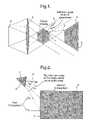
- FIG. 1diagrammatically illustrates a plan view of part of the display system, showing a facet with its normal vector N projected outside of the view volume, and a vector V projected into the view volume.
- FIG. 2illustrates the method currently used to find vector V min .
- FIG. 1shows a facet 1 being projected by a display system comprising a CGH design plane (CDP) 8 and a lens 9 , and having a normal 3 that does not intersect with the view volume 4 .
- CDPCGH design plane
- the view vector 2is defined as the vector from the facet centre to the point on the rear face 5 of the viewing volume 4 where the view of the facet 1 is at its maximum. As, in this example, intersection from the normal 3 with the view volume 4 does not occur here, the dilution factor can be applied to the point population to save processing effort.
- the vector V minneeds to be found such that the angle ⁇ between V 2 and N 1 is minimised.
- all vectors that enter the view volume 4will pass through the rear face 5 of the view volume 4 .
- the vector V minwill always lie on the edge of the rear face 5 if N 1 does not itself pass through the view volume 4 .
- V minpasses through the point on the rear face 5 of the view volume 4 where the facet 1 will be seen at its fullest. This point is found by a recursive, iterative, binary chop technique, discussed below.
- the dilution factor d used in the current implementationis the cosine of the angle between these two vectors, i.e.
- the dilutionis directly proportional to the apparent reduction in area of the facet 1 as seen from the closest point in the viewing volume to the facet normal 3 .
- the angle ⁇will always be no greater than 90°. Therefore, d will always be in the range 0 ⁇ d ⁇ 1. The point density on the facet in question is therefore simply multiplied by the factor d.
- Nis the total number of pixels in the CGH
- n pis the total number of visible object points for the given pixel being calculated.
- a pis the light amplitude for a given point p.
- r pis the distance between the object point to the CGH pixel.
- ⁇ pis the phase for that object point.
- Abs[N p dot V p ] at the right of the equationacts as an obliquity factor to ensure energy conservation.
- V pis the vector from the object point to the particular pixel being calculated and N p is the normal vector from the pixel.
- FIG. 2shows the method currently used to find the vector V min .
- Thisis a vector from the facet centre 6 to the part of the view volume ( 4 , not shown) where the facet 1 is seen most face-on.
- the algorithm used by the CGH codefinds this point by using a binary-chop method on each edge in turn. For each edge 7 it tests to see if the middle of one half can see more of the facet 1 than the other half. It then chooses the better half and repeats the test on that part and so on, each time getting closer until some arbitrary precision is reached.
- the cosine of the angle between this point to the facet mid-point and the facet normalis used as the dilution factor, as shown above.
- the workings of the algorithmare as follows.
- the point along the edge 7 which forms the smallest angle from the facet 1 with respect to the facet normal 3is found by a binary chop method.
- the midpoints of each half (A 1 and B 1 )are tested and the better half is selected (the top half in this example).
- the midpoints of each half of this part (A 2 and B 2 )are then tested and again the better half is selected. This process continues until the desired precision is reached.
- One possible alternativeis to locate where the facet normal vector intersects the plane of the view volume rear face and then find the closest point on the rear face to this point.
- the current inventionhas been implemented on an Active-Tiling® Computer Generated Hologram (CGH) display system, though any 3D display system could be used, if it is capable of displaying true 3D images, and uses arrays of points to make up surfaces.
- the computer systemitself could be a standalone unit, or could have remote elements connected by a network.
- the Active Tiling systemis a means of producing holographic moving images by rapidly replaying different frames of a holographic animation.
- the Active Tiling systemessentially comprises a system for directing light from a light source onto a first spatial light modulator (SLM) means and relaying a number of SLM subframes of the modulated light from the first high speed SLM means onto a second spatially complex SLM.
- the CGHis projected from this second SLM.
- the full CGH patternis split up into subframes in which the number of pixels is equal to the complexity of the first SLM. These frames are displayed time-sequentially on the first SLM and each frame is projected to a different part of the second SLM. The full image is thus built up on the second SLM over time.
- the first SLM meanscomprises an array of the first SLMs that each tile individual subframes on the second SLM over their respective areas.
- the first SLM of such a systemis of a type in which the modulation pattern can be changed quickly, compared to that of the second SLM. Thus its updating frame rate is greater than the read-out frame rate of the second SLM.
- the Active Tiling systemhas the benefit that the image produced at the second SLM, which is addressed at a rate much slower than that of the first SLM array, is effectively governed by the operation of the first SLM. This permits a trade off between the temporal information available in the high frame rate SLMs used in the SLM array and the high spatial resolution that can be achieved using current optically addressed SLMs as the second SLM. In this way, a high spatial resolution image can be rapidly written to an SLM using a sequence of lower resolution images.
Landscapes
- Physics & Mathematics (AREA)
- General Physics & Mathematics (AREA)
- Holo Graphy (AREA)
- Processing Or Creating Images (AREA)
Abstract
Description
- representing an object as a set of planar facets;
- calculating which facets are not displayed face-on to a view volume;
- applying a density of object points to each facet, where a reduced density is applied to those facets not displayed face-on to a view volume.
where d is the dilution factor applied to the facet containing point p. Energy conservation over the CGH is thus maintained.
Claims (22)
Priority Applications (1)
| Application Number | Priority Date | Filing Date | Title |
|---|---|---|---|
| US11/483,980US7417634B2 (en) | 2000-11-07 | 2006-07-11 | Three dimensional display |
Applications Claiming Priority (6)
| Application Number | Priority Date | Filing Date | Title |
|---|---|---|---|
| GB0027104AGB0027104D0 (en) | 2000-11-07 | 2000-11-07 | Improved three dimensional display |
| GB0027104.9 | 2000-11-07 | ||
| US24701100P | 2000-11-13 | 2000-11-13 | |
| US10/415,982US20040046758A1 (en) | 2000-11-07 | 2001-11-05 | Three dimensional display |
| PCT/GB2001/004886WO2002039387A1 (en) | 2000-11-07 | 2001-11-05 | Improved three dimensional display |
| US11/483,980US7417634B2 (en) | 2000-11-07 | 2006-07-11 | Three dimensional display |
Related Parent Applications (3)
| Application Number | Title | Priority Date | Filing Date |
|---|---|---|---|
| US10415982Continuation | 2001-11-05 | ||
| PCT/GB2001/004886ContinuationWO2002039387A1 (en) | 2000-11-07 | 2001-11-05 | Improved three dimensional display |
| US10/415,982ContinuationUS20040046758A1 (en) | 2000-11-07 | 2001-11-05 | Three dimensional display |
Publications (2)
| Publication Number | Publication Date |
|---|---|
| US20070040829A1 US20070040829A1 (en) | 2007-02-22 |
| US7417634B2true US7417634B2 (en) | 2008-08-26 |
Family
ID=26245244
Family Applications (2)
| Application Number | Title | Priority Date | Filing Date |
|---|---|---|---|
| US10/415,982AbandonedUS20040046758A1 (en) | 2000-11-07 | 2001-11-05 | Three dimensional display |
| US11/483,980Expired - LifetimeUS7417634B2 (en) | 2000-11-07 | 2006-07-11 | Three dimensional display |
Family Applications Before (1)
| Application Number | Title | Priority Date | Filing Date |
|---|---|---|---|
| US10/415,982AbandonedUS20040046758A1 (en) | 2000-11-07 | 2001-11-05 | Three dimensional display |
Country Status (4)
| Country | Link |
|---|---|
| US (2) | US20040046758A1 (en) |
| EP (1) | EP1332474A1 (en) |
| JP (1) | JP2005502095A (en) |
| WO (1) | WO2002039387A1 (en) |
Families Citing this family (5)
| Publication number | Priority date | Publication date | Assignee | Title |
|---|---|---|---|---|
| DE102007013431B4 (en)* | 2007-03-15 | 2018-07-05 | Seereal Technologies S.A. | Method and apparatus for reconstructing a three-dimensional scene with corrected visibility |
| WO2019143729A1 (en)* | 2018-01-16 | 2019-07-25 | Pacific Light & Hologram, Inc. | Three-dimensional displays using electromagnetic field computations |
| JP7514790B2 (en)* | 2021-04-14 | 2024-07-11 | Kddi株式会社 | Computer generated hologram generating device, method and program |
| JP7599400B2 (en)* | 2021-10-14 | 2024-12-13 | Kddi株式会社 | Computer generated hologram generating device, method and program |
| US12300132B2 (en) | 2023-05-12 | 2025-05-13 | Pacific Light & Hologram, Inc. | Holographically displaying three-dimensional objects |
Citations (31)
| Publication number | Priority date | Publication date | Assignee | Title |
|---|---|---|---|---|
| US3829838A (en)* | 1970-11-05 | 1974-08-13 | Battelle Development Corp | Computer-controlled three-dimensional pattern generator |
| US3957353A (en)* | 1974-03-08 | 1976-05-18 | The Board Of Trustees Of The Leland Stanford University | Multiemulsion transparency providing separate phase and amplitude control |
| US4695973A (en)* | 1985-10-22 | 1987-09-22 | The United States Of America As Represented By The Secretary Of The Air Force | Real-time programmable optical correlator |
| US4701006A (en)* | 1985-02-20 | 1987-10-20 | Stanford University | Optical-digital hologram recording |
| US5039223A (en)* | 1988-07-13 | 1991-08-13 | Kabushiki Kaisha Topcon | Interferometer for measuring aspherical form with the utilization of computer generated hologram |
| US5119214A (en)* | 1990-03-26 | 1992-06-02 | Matsushita Electric Industrial Co., Ltd. | Method for forming a computer generated hologram |
| US5194971A (en)* | 1986-10-14 | 1993-03-16 | American Bank Note Holographics, Inc. | Computer aided holography and holographic computer graphics |
| US5220622A (en)* | 1989-11-28 | 1993-06-15 | Stc Plc | Data base searching |
| EP0590828A2 (en) | 1992-09-30 | 1994-04-06 | Fujitsu Limited | Stereoscopic display method and apparatus |
| US5347375A (en)* | 1991-11-26 | 1994-09-13 | Kabushiki Kaisha Toshiba | Computer-assisted holographic image formation technique which determines interference pattern data used to form the holographic |
| US5400155A (en)* | 1992-10-14 | 1995-03-21 | Fujitsu Limited | Hologram information forming method |
| US5610733A (en)* | 1994-02-28 | 1997-03-11 | Digital Optics Corporation | Beam-homogenizer |
| US5652666A (en)* | 1994-03-31 | 1997-07-29 | Texas Instruments Incorporated | Holographic 3-D display system with spatial light modulator |
| US5666226A (en)* | 1993-05-25 | 1997-09-09 | Sharp Kabushiki Kaisha | Optical apparatus |
| US5682214A (en)* | 1990-04-05 | 1997-10-28 | Seiko Epson Corporation | Optical apparatus for controlling the wavefront of a coherent light |
| US5724447A (en)* | 1994-05-17 | 1998-03-03 | Olympus Optical Co., Ltd. | Optical transform system for three-dimensional object recognition |
| US5812434A (en)* | 1995-06-16 | 1998-09-22 | Fujitsu Limited | Electromagnetic field strength calculator having function of displaying currents to be analyzed |
| EP0880110A2 (en) | 1997-05-22 | 1998-11-25 | Nippon Telegraph And Telephone Corporation | Method and apparatus for displaying computer generated holograms |
| US5891030A (en)* | 1997-01-24 | 1999-04-06 | Mayo Foundation For Medical Education And Research | System for two dimensional and three dimensional imaging of tubular structures in the human body |
| US5914721A (en)* | 1991-06-28 | 1999-06-22 | Lim; Hong Lip | Visibility calculations for 3D computer graphics |
| US5923331A (en)* | 1994-09-30 | 1999-07-13 | Thomson Broadband Systems | Method of generation of computer-generated images using a spherical buffer |
| US5929860A (en)* | 1996-01-11 | 1999-07-27 | Microsoft Corporation | Mesh simplification and construction of progressive meshes |
| WO1999039308A1 (en) | 1998-01-30 | 1999-08-05 | Jiankun Li | 3d mesh compression and coding |
| US5953013A (en)* | 1994-01-18 | 1999-09-14 | Hitachi Medical Corporation | Method of constructing three-dimensional image according to central projection method and apparatus for same |
| US6016224A (en)* | 1995-12-18 | 2000-01-18 | Olympus Optical Co., Ltd. | Multiple image optics system |
| US6025938A (en)* | 1994-02-28 | 2000-02-15 | Digital Optics Corporation | Beam homogenizer |
| US6373489B1 (en)* | 1999-01-12 | 2002-04-16 | Schlumberger Technology Corporation | Scalable visualization for interactive geometry modeling |
| US6437919B1 (en)* | 1997-10-15 | 2002-08-20 | Holographic Imaging Llc | System for the production of a dynamic image for display |
| US6498607B1 (en)* | 1999-01-29 | 2002-12-24 | Mitsubishi Electric Research Laboratories, Inc. | Method for generating graphical object represented as surface elements |
| US6639597B1 (en)* | 2000-02-28 | 2003-10-28 | Mitsubishi Electric Research Laboratories Inc | Visibility splatting and image reconstruction for surface elements |
| US7068403B2 (en)* | 2003-02-12 | 2006-06-27 | Dai Nippon Printing Co., Ltd. | Computer-generated hologram |
- 2001
- 2001-11-05JPJP2002541631Apatent/JP2005502095A/ennot_activeWithdrawn
- 2001-11-05USUS10/415,982patent/US20040046758A1/ennot_activeAbandoned
- 2001-11-05EPEP01980701Apatent/EP1332474A1/ennot_activeWithdrawn
- 2001-11-05WOPCT/GB2001/004886patent/WO2002039387A1/ennot_activeApplication Discontinuation
- 2006
- 2006-07-11USUS11/483,980patent/US7417634B2/ennot_activeExpired - Lifetime
Patent Citations (36)
| Publication number | Priority date | Publication date | Assignee | Title |
|---|---|---|---|---|
| US3829838A (en)* | 1970-11-05 | 1974-08-13 | Battelle Development Corp | Computer-controlled three-dimensional pattern generator |
| US3957353A (en)* | 1974-03-08 | 1976-05-18 | The Board Of Trustees Of The Leland Stanford University | Multiemulsion transparency providing separate phase and amplitude control |
| US4701006A (en)* | 1985-02-20 | 1987-10-20 | Stanford University | Optical-digital hologram recording |
| US4695973A (en)* | 1985-10-22 | 1987-09-22 | The United States Of America As Represented By The Secretary Of The Air Force | Real-time programmable optical correlator |
| US5194971A (en)* | 1986-10-14 | 1993-03-16 | American Bank Note Holographics, Inc. | Computer aided holography and holographic computer graphics |
| US5039223A (en)* | 1988-07-13 | 1991-08-13 | Kabushiki Kaisha Topcon | Interferometer for measuring aspherical form with the utilization of computer generated hologram |
| US5220622A (en)* | 1989-11-28 | 1993-06-15 | Stc Plc | Data base searching |
| US5119214A (en)* | 1990-03-26 | 1992-06-02 | Matsushita Electric Industrial Co., Ltd. | Method for forming a computer generated hologram |
| US5682214A (en)* | 1990-04-05 | 1997-10-28 | Seiko Epson Corporation | Optical apparatus for controlling the wavefront of a coherent light |
| US6618047B1 (en)* | 1991-06-28 | 2003-09-09 | Fuzzysharp Technologies, Inc. | Visibility calculations for 3d computer graphics |
| US5914721A (en)* | 1991-06-28 | 1999-06-22 | Lim; Hong Lip | Visibility calculations for 3D computer graphics |
| US6172679B1 (en)* | 1991-06-28 | 2001-01-09 | Hong Lip Lim | Visibility calculations for 3D computer graphics |
| US5347375A (en)* | 1991-11-26 | 1994-09-13 | Kabushiki Kaisha Toshiba | Computer-assisted holographic image formation technique which determines interference pattern data used to form the holographic |
| US5483364A (en)* | 1992-09-30 | 1996-01-09 | Fujitsu Limited | Holographic steroscopic display method and apparatus using high and low sample point densities of feature and non-lecture portions of a holographic sterogram |
| EP0590828A2 (en) | 1992-09-30 | 1994-04-06 | Fujitsu Limited | Stereoscopic display method and apparatus |
| US5400155A (en)* | 1992-10-14 | 1995-03-21 | Fujitsu Limited | Hologram information forming method |
| US5666226A (en)* | 1993-05-25 | 1997-09-09 | Sharp Kabushiki Kaisha | Optical apparatus |
| US5953013A (en)* | 1994-01-18 | 1999-09-14 | Hitachi Medical Corporation | Method of constructing three-dimensional image according to central projection method and apparatus for same |
| US6025938A (en)* | 1994-02-28 | 2000-02-15 | Digital Optics Corporation | Beam homogenizer |
| US5610733A (en)* | 1994-02-28 | 1997-03-11 | Digital Optics Corporation | Beam-homogenizer |
| US5652666A (en)* | 1994-03-31 | 1997-07-29 | Texas Instruments Incorporated | Holographic 3-D display system with spatial light modulator |
| US5724447A (en)* | 1994-05-17 | 1998-03-03 | Olympus Optical Co., Ltd. | Optical transform system for three-dimensional object recognition |
| US5923331A (en)* | 1994-09-30 | 1999-07-13 | Thomson Broadband Systems | Method of generation of computer-generated images using a spherical buffer |
| US5812434A (en)* | 1995-06-16 | 1998-09-22 | Fujitsu Limited | Electromagnetic field strength calculator having function of displaying currents to be analyzed |
| US6016224A (en)* | 1995-12-18 | 2000-01-18 | Olympus Optical Co., Ltd. | Multiple image optics system |
| US5929860A (en)* | 1996-01-11 | 1999-07-27 | Microsoft Corporation | Mesh simplification and construction of progressive meshes |
| US5963209A (en)* | 1996-01-11 | 1999-10-05 | Microsoft Corporation | Encoding and progressive transmission of progressive meshes |
| US6046744A (en)* | 1996-01-11 | 2000-04-04 | Microsoft Corporation | Selective refinement of progressive meshes |
| US5891030A (en)* | 1997-01-24 | 1999-04-06 | Mayo Foundation For Medical Education And Research | System for two dimensional and three dimensional imaging of tubular structures in the human body |
| EP0880110A2 (en) | 1997-05-22 | 1998-11-25 | Nippon Telegraph And Telephone Corporation | Method and apparatus for displaying computer generated holograms |
| US6437919B1 (en)* | 1997-10-15 | 2002-08-20 | Holographic Imaging Llc | System for the production of a dynamic image for display |
| WO1999039308A1 (en) | 1998-01-30 | 1999-08-05 | Jiankun Li | 3d mesh compression and coding |
| US6373489B1 (en)* | 1999-01-12 | 2002-04-16 | Schlumberger Technology Corporation | Scalable visualization for interactive geometry modeling |
| US6498607B1 (en)* | 1999-01-29 | 2002-12-24 | Mitsubishi Electric Research Laboratories, Inc. | Method for generating graphical object represented as surface elements |
| US6639597B1 (en)* | 2000-02-28 | 2003-10-28 | Mitsubishi Electric Research Laboratories Inc | Visibility splatting and image reconstruction for surface elements |
| US7068403B2 (en)* | 2003-02-12 | 2006-06-27 | Dai Nippon Printing Co., Ltd. | Computer-generated hologram |
Non-Patent Citations (3)
| Title |
|---|
| Article; "2001-A Holographic Odyssey"; Eureka, Feb. 2001, p. 20 and 21. |
| Ichioka et al., "Optical information processing", Proceedings of the IEEE, vol. 84, Issue 5, pp. 694-719, May 1996.* |
| Ihori et al.; "Fast optical measurement of nonuniform electric field vector mapping in a dielectric liquid" Dielectric Liquids, 1999. (ICDL '99) Proceedings of the 1999 IEEE 13th International Conference on Jul. 20-25, 1999 pp. 345-348.* |
Also Published As
| Publication number | Publication date |
|---|---|
| WO2002039387A1 (en) | 2002-05-16 |
| EP1332474A1 (en) | 2003-08-06 |
| US20040046758A1 (en) | 2004-03-11 |
| JP2005502095A (en) | 2005-01-20 |
| US20070040829A1 (en) | 2007-02-22 |
Similar Documents
| Publication | Publication Date | Title |
|---|---|---|
| US11460808B2 (en) | Method for generating a head up display for an aircraft using video holograms in real time with the help of sub-holograms | |
| US7649532B2 (en) | Computer generated hologram display system | |
| US7969633B2 (en) | Method and device for computing computer-generated video holograms | |
| US8072488B2 (en) | Holographic apparatus and method | |
| US7782510B2 (en) | Computer generated hologram | |
| US7768684B2 (en) | 3D display | |
| CA2652973C (en) | Method and device for rendering and generating computer-generated video holograms | |
| US5483364A (en) | Holographic steroscopic display method and apparatus using high and low sample point densities of feature and non-lecture portions of a holographic sterogram | |
| US7516170B2 (en) | Computer graphics systems and methods using stratification by rank-1 lattices | |
| US7417634B2 (en) | Three dimensional display | |
| US20100149314A1 (en) | Method for Rendering and Generating Color Video Holograms in Real Time | |
| US20100149312A1 (en) | Analytical Method for Computing Video Holograms in Real Time | |
| EP1612624B1 (en) | Method of computing a computer generated hologram | |
| US20040021918A1 (en) | 3D Display | |
| US6842184B2 (en) | Three dimensional stochastic screen for LCD and video | |
| US20230025687A1 (en) | Method for generating a head up display for an aircraft using video holograms in real time with the help of sub-holograms | |
| Iwata | Grating image technology |
Legal Events
| Date | Code | Title | Description |
|---|---|---|---|
| AS | Assignment | Owner name:F. POSZAT HU, LLC, DELAWARE Free format text:ASSIGNMENT OF ASSIGNORS INTEREST;ASSIGNOR:QINETIQ LIMITED COMPANY;REEL/FRAME:019140/0578 Effective date:20070327 | |
| STCF | Information on status: patent grant | Free format text:PATENTED CASE | |
| CC | Certificate of correction | ||
| FPAY | Fee payment | Year of fee payment:4 | |
| FPAY | Fee payment | Year of fee payment:8 | |
| MAFP | Maintenance fee payment | Free format text:PAYMENT OF MAINTENANCE FEE, 12TH YEAR, LARGE ENTITY (ORIGINAL EVENT CODE: M1553); ENTITY STATUS OF PATENT OWNER: LARGE ENTITY Year of fee payment:12 | |
| AS | Assignment | Owner name:INTELLECTUAL VENTURES ASSETS 191 LLC, DELAWARE Free format text:ASSIGNMENT OF ASSIGNORS INTEREST;ASSIGNOR:F. POSZAT HU, L.L.C.;REEL/FRAME:062666/0463 Effective date:20221222 | |
| AS | Assignment | Owner name:INTELLECTUAL VENTURES ASSETS 186 LLC, DELAWARE Free format text:SECURITY INTEREST;ASSIGNOR:MIND FUSION, LLC;REEL/FRAME:063295/0001 Effective date:20230214 Owner name:INTELLECTUAL VENTURES ASSETS 191 LLC, DELAWARE Free format text:SECURITY INTEREST;ASSIGNOR:MIND FUSION, LLC;REEL/FRAME:063295/0001 Effective date:20230214 | |
| AS | Assignment | Owner name:MIND FUSION, LLC, WASHINGTON Free format text:ASSIGNMENT OF ASSIGNORS INTEREST;ASSIGNOR:INTELLECTUAL VENTURES ASSETS 191 LLC;REEL/FRAME:064270/0685 Effective date:20230214 |