US7417625B2 - Method and system for providing input mechanisms on a handheld electronic device - Google Patents
Method and system for providing input mechanisms on a handheld electronic deviceDownload PDFInfo
- Publication number
- US7417625B2 US7417625B2US10/834,406US83440604AUS7417625B2US 7417625 B2US7417625 B2US 7417625B2US 83440604 AUS83440604 AUS 83440604AUS 7417625 B2US7417625 B2US 7417625B2
- Authority
- US
- United States
- Prior art keywords
- keys
- user
- handheld device
- input
- key
- Prior art date
- Legal status (The legal status is an assumption and is not a legal conclusion. Google has not performed a legal analysis and makes no representation as to the accuracy of the status listed.)
- Expired - Fee Related, expires
Links
Images


Classifications
- G—PHYSICS
- G06—COMPUTING OR CALCULATING; COUNTING
- G06F—ELECTRIC DIGITAL DATA PROCESSING
- G06F1/00—Details not covered by groups G06F3/00 - G06F13/00 and G06F21/00
- G06F1/16—Constructional details or arrangements
- G06F1/1613—Constructional details or arrangements for portable computers
- G06F1/1615—Constructional details or arrangements for portable computers with several enclosures having relative motions, each enclosure supporting at least one I/O or computing function
- G06F1/1616—Constructional details or arrangements for portable computers with several enclosures having relative motions, each enclosure supporting at least one I/O or computing function with folding flat displays, e.g. laptop computers or notebooks having a clamshell configuration, with body parts pivoting to an open position around an axis parallel to the plane they define in closed position
- G—PHYSICS
- G06—COMPUTING OR CALCULATING; COUNTING
- G06F—ELECTRIC DIGITAL DATA PROCESSING
- G06F1/00—Details not covered by groups G06F3/00 - G06F13/00 and G06F21/00
- G06F1/16—Constructional details or arrangements
- G06F1/1613—Constructional details or arrangements for portable computers
- G06F1/1633—Constructional details or arrangements of portable computers not specific to the type of enclosures covered by groups G06F1/1615 - G06F1/1626
- G06F1/1662—Details related to the integrated keyboard
- G—PHYSICS
- G06—COMPUTING OR CALCULATING; COUNTING
- G06F—ELECTRIC DIGITAL DATA PROCESSING
- G06F3/00—Input arrangements for transferring data to be processed into a form capable of being handled by the computer; Output arrangements for transferring data from processing unit to output unit, e.g. interface arrangements
- G06F3/01—Input arrangements or combined input and output arrangements for interaction between user and computer
- G06F3/02—Input arrangements using manually operated switches, e.g. using keyboards or dials
- G06F3/0202—Constructional details or processes of manufacture of the input device
- G06F3/0221—Arrangements for reducing keyboard size for transport or storage, e.g. foldable keyboards, keyboards with collapsible keys
- H—ELECTRICITY
- H01—ELECTRIC ELEMENTS
- H01H—ELECTRIC SWITCHES; RELAYS; SELECTORS; EMERGENCY PROTECTIVE DEVICES
- H01H9/00—Details of switching devices, not covered by groups H01H1/00 - H01H7/00
- H01H9/02—Bases, casings, or covers
- H01H9/0214—Hand-held casings
- H01H9/0235—Hand-held casings specially adapted for remote control, e.g. of audio or video apparatus
- H01H2009/0257—Multisided remote control, comprising control or display elements on at least two sides, e.g. front and back surface
- H—ELECTRICITY
- H01—ELECTRIC ELEMENTS
- H01H—ELECTRIC SWITCHES; RELAYS; SELECTORS; EMERGENCY PROTECTIVE DEVICES
- H01H2217/00—Facilitation of operation; Human engineering
- H01H2217/002—Facilitation of operation; Human engineering actuable from both sides
- H—ELECTRICITY
- H01—ELECTRIC ELEMENTS
- H01H—ELECTRIC SWITCHES; RELAYS; SELECTORS; EMERGENCY PROTECTIVE DEVICES
- H01H2223/00—Casings
- H01H2223/046—Casings convertible
- H01H2223/048—Casings convertible assembled by removable part
Definitions
- the present inventionrelates to handheld electronic devices, and more particularly to input mechanisms on a handheld electronic device.
- a mobile phonehas a minimum number of alphanumeric keys, and additional input keys, e.g., navigation and select keys. These keys are typically located on one face of the device, which also typically includes a display, e.g., an LCD, so that the user can see what he or she has entered, or so that the user can access other functions of the device.
- a displaye.g., an LCD
- the size of the keys and/or display, and the spacing between keysis usually decreased. Nevertheless, because the keys are so small and the number so many, it becomes difficult to distinguish between the keys. Moreover, even if the user can make such a distinction, it is difficult to press the desired key because the space between keys is so small. For individuals with large fingers, this can be particularly frustrating.
- direction related keysi.e., navigation keys
- the side surfaceis thin and the keys must be positioned in a row along the side surface. Accordingly, navigation keys assigned to allow the user to navigate in a direction perpendicular to the row, i.e., right or left if the keys are on the left or right side of the device, are not intuitive for the user.
- Other devicesoffer a touchpad on a backside of the device, i.e., on the surface opposing the device face. (See, e.g., U. S. Pat. No. 5,543,588, entitled “Touch Pad Driven Handheld Computing Device” issued Aug.
- Each of the above described devicespresents an additional disadvantage as well.
- the location of the navigation mechanismis fixed.
- the userif the user is not comfortable having the navigation mechanism facing away from him or her as the user is viewing the display, the user cannot change the position of the navigation mechanism.
- the system and methodshould be highly intuitive for the user, while being cost effective and efficient.
- the present inventionaddresses such a need.
- the handheld electronic deviceincludes a casing having a first surface and an opposing second surface, where the first surface includes a display on which a user interface is displayed to a user of the device, a plurality of input keys on the second surface, a layout of the plurality of input keys displayed on the display, and means for allowing the user to enter commands into the device by pressing at least one of the plurality of input keys, whereby the layout allows the user to select an appropriate input key of the plurality of input keys associated with a particular command without viewing the input key.
- the handheld electronic deviceincludes a casing having a first surface and an opposing second surface, where the first surface includes a display on which a user interface is displayed to a user of the device, a hinge mechanism between the first and second surfaces such that the second surface rotates back and forth between a first position and a second position, where the first position is when the second surface is opposing the first surface and facing away from the user, and the second position is when the second surface is substantially co-planar with the first surface and facing the use, at least one input mechanism on the second surface, and means for allowing the user to enter commands into the device by activating the at least one input mechanism.
- buttonsBy locating input mechanisms such as input keys on another surface, i.e., the back face of the device, more or better features can be included on the surface facing the user, i.e., the front face. For instance, because fewer buttons are located on the front face, there is more space available for a larger display. Also, the button arrangement is less cluttered and the spacing between buttons can be increased so that the likelihood of pressing an incorrect button is decreased.
- a layout of the input mechanismsis displayed to the user so that the user can activate a desired mechanism.
- FIGS. 1A and 1Bare front and back views, respectively, of a handheld electronic device according to a preferred embodiment of the present invention.
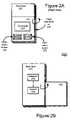
- FIGS. 2A , 2 B and 2 Cback and front views of a handheld electronic device according to another preferred embodiment of the present invention.
- FIGS. 3A and 3Bare back and front views, respectively, of a handheld electronic device according to a third preferred embodiment of the present invention.
- FIG. 4is a flowchart illustrating a method for displaying the layout of the input keys via touch sensitive keys according to a preferred embodiment of the present invention.
- FIG. 5is a flowchart illustrating a process for reassigning direction related keys according to a preferred embodiment of the present invention.
- the present inventionrelates to handheld electronic devices, and more particularly to, input mechanisms on a handheld electronic device.
- the following descriptionis presented to enable one of ordinary skill in the art to make and use the invention and is provided in the context of a patent application and its requirements.
- Various modifications to the preferred embodiments and the generic principles and features described hereinwill be readily apparent to those skilled in the art.
- the preferred embodimentsare described with respect to a mobile phone, the principles described can also be applied to any handheld electronic device, such as a PDA, digital camera, MP3 Player, and the like.
- the present inventionis not intended to be limited to the embodiment shown but is to be accorded the widest scope consistent with the principles and features described herein.
- the present inventionis described with respect to two embodiments.
- the total number of input keys cluttered onto a front face of a handheld electronic deviceis reduced by locating a plurality of input keys on another surface, such as the back face of the device.
- a layout of the plurality of input keysis displayed to the user on the front face of the device so that the user can determine the appropriate key to press.
- the front facecan include a larger display, larger input keys and adequate spacing between the remaining input keys, without sacrificing the functionality provided by the plurality of input keys on the other surface.
- the plurality of keysare on the back face of the device, the intuitive nature of directional keys can be maintained.
- At least one input mechanisme.g., a plurality of direction related keys and/or a select key
- a panelthat is hinged to the device in such a manner that the user can “flip out” the panel.
- the paneland keys
- the userhas access to the plurality of keys in either position so that the user can choose in what position he or she would like to activate the at least one input mechanism.
- the deviceincludes a sensor that senses the position of the panel, i.e., whether it is in the open or closed position.
- the sensoris coupled to an assigner that controls the directional assignment of direction related keys. The assigner ensures that the intuitive nature of the direction related keys is maintained with respect to the user.
- FIGS. 1A and 1Bare front and back views, respectively, of a handheld mobile phone according to the first aspect of a preferred embodiment of the present invention.
- the phone 100includes a front face 120 and an opposing back face 122 .
- the front face 120 of the mobile phone 100( FIG. 1A ) includes a display 140 and ten (10) alphanumeric keys 160 typical of a phone.
- the display 140is used to display a user interface (not shown) that typically includes a menu of functions from which the user can choose.
- input mechanismsincluding direction related keys 123 - 128 and non-direction related keys, e.g., a select button 129 , are located on the back face 122 ( FIG. 1B ) of the mobile phone 100 .
- the input mechanismswere to be located on the front face 120 , the size of the display 140 and keys and/or spacing between the keys would necessarily decrease.
- the usability of the phone 100is significantly improved.
- the directional aspects of the direction related keys 123 - 128are correlated to the user's perspective.
- the directional aspectsare opposite to those viewed from the back face 122 .
- the input key on the left side of the back face 126corresponds to the user's right when the user is viewing the front face 120 , and is assigned to be a right-menu button 126 .
- the input key on the right side of the back face 128corresponds to the user's left when the user is viewing the front face 120 , and is accordingly assigned to be a left-menu button 128 .
- each of the input keys 123 - 129includes an embossed pattern 130 a , 130 b on a surface touched by the user to assist the user in identifying the key, e.g., 126 .
- a layout 142 of the input keys 123 - 129is displayed on the display 140 ( FIG. 1A ).
- the layout 142is displayed upon request by the user by activating a display layout key 161 located on either the front face 120 or the back face 122 of the device.
- the input keys 123 - 129are responsive to more than one touch pressure, i.e., they are touch-sensitive.
- a “light” touch at a first pressureindicates a request to display the layout 142
- a “heavy” touch at a second pressureenters a command associated with the input key, e.g., 126 .
- a touch counter(not shown) is used to count the number of times the user applies the light touch to one or more input keys 123 - 129 . Only when the number of light touches exceeds a certain threshold value, e.g., three (3) touches, does the layout 142 display.
- FIG. 4is a flowchart illustrating a method for displaying the layout 142 of the input keys 123 - 129 via the touch sensitive keys according to a preferred embodiment of the present invention.
- the processbegins when an input event is detected (step 400 ), i.e., when an input key, e.g., 126 , is touched.
- the device 100determines whether the input event is a light touch (step 402 ). If it is, then it is determined whether the layout 142 is already displayed on the display 140 (step 404 ). If the layout 142 is displayed, then the input key touched 126 is highlighted on the layout 142 (step 412 ) to indicate to the user which key was touched.
- step 404If the layout 142 is not already displayed (step 404 ), the touch counter (not shown) is incremented (step 406 ), and if the touch counter exceeds a certain threshold value (step 408 ), then the layout 142 is displayed and the touched key 126 is highlighted on the layout 142 (step 410 ). If the touch counter does not exceed the threshold (step 408 ), the process waits for another input event (step 400 ).
- the touch counteris reset (step 414 ) and the layout 142 is removed from the display 140 (step 416 ). Then, the device 100 handles the input event (step 418 ), i.e., performs the command associated with the touched key 126 .
- FIG. 4illustrates one preferred process for controlling the display of the layout 142 .
- the layout 142can be automatically removed, or the layout 142 can be automatically removed after a period of no activity. Such methods would be within the scope of the present invention.
- the deviceis provided with a panel containing at least one input mechanism.
- the panelrotates to and from a first (closed) position from and to a second (open) position.
- FIGS. 2A and 2Bare diagrams depicting a back face 220 ′ of a handheld mobile phone 200 according to the second preferred embodiment of the present invention.
- the panel 222is coupled to the device 200 by a hinge mechanism 230 such that the panel 222 rotates around the hinge mechanism 230 from the closed position (shown in FIG. 2A ) to the open position ( FIG. 2B ) in the direction illustrated by the circular arrow, as shown in FIGS. 2A and 2B .
- the hinge mechanism 230can also be located on the opposite side so that the panel 222 rotates in the opposite direction indicated by the arrow.
- input mechanismssuch as a touchpad 224 and direction-related keys, e.g., right and left menu buttons 226 , 228 , are provided on the panel 222 .
- the input mechanisms 224 , 226 , 228are operational in both the closed and open positions.
- the directional assignments for direction-related keys 226 , 228are dependent on the position of the panel 222 .
- the position of the panel 222is determined preferably by a sensor 232 located on the back face 220 ′ of the device 200 ( FIG. 2B ).
- the senor 232can be a contact point that completes a circuit (not shown) when it comes in contact with a back surface 222 ′ of the panel 222 , or vice versa.
- Other methods of implementing the sensor 232would be readily appreciated by those skilled in the art.
- the sensor 232is coupled to an assigner 234 , which controls the directional assignment of the direction-related keys 226 , 228 depending on the position of the panel 222 , i.e., whether the panel 222 is facing away from the user or toward the user.
- an assigner 234controls the directional assignment of the direction-related keys 226 , 228 depending on the position of the panel 222 , i.e., whether the panel 222 is facing away from the user or toward the user.
- the panel 222is in the closed (first) position ( FIG. 2A )
- the panel 222is facing away from the user.
- the key 226 on the left side of the panel 222is assigned to the right-menu button.
- the panel 222is in the open (second) position ( FIG. 2C )
- itis facing toward the user and the same key 226 on the left side of the panel 222 is reassigned to the left-menu button.
- the assigner 234applies the same adjustment to the directional signals interpreted by the touchpad 224 .
- a finger trace from the left side of the touchpad 224 to the right side of the touchpad 224correlates to the movement of a cursor on the display 240 from the right side of the display 240 to the left side of the display 240 .
- the direction of the finger tracecorresponds directly with the movement of the cursor on the display 240 .
- FIGS. 3A and 3Bare back and front views, respectively, of a handheld mobile phone according to a third preferred embodiment of the present invention.
- This embodimentis similar to that illustrated in FIGS. 2A-2C except that the hinging mechanism 330 is located on a bottom side of the phone 300 such that the panel 322 “flips” down, as illustrated in FIG. 3B .
- the directional assignments for input keys associated with a horizontal direction 326 , 328 , 336 , 338i.e. left or right, are not affected by the position of the panel 322 .
- the assignments for the input keys associated with a vertical direction 332 , 334are dependent on the panel 322 position.
- FIGS. 3A and 3Bshow the hinging mechanism 330 located on the bottom side of the phone 300 , it is also possible to locate the hinging mechanism 330 on a top side of the phone 300 such that the panel 322 “flips” up.
- FIG. 5is a flowchart illustrating a method for reassigning direction sensitive keys according to a preferred embodiment of the present invention.
- the processbegins when an input event is detected (step 500 ), i.e., when the user presses an input key 226 , 228 .
- the device 200determines whether the pressed key, i.e., 226 , is a direction related button (step 502 ). If the pressed key is not a direction related button, i.e., the pressed key is an alphanumeric key or a select button 350 ( FIG. 3A ), the device 200 handles the input event (step 510 ), i.e., performs the command associated with the pressed key.
- the pressed keyis a direction related button 226 (step 502 )
- the sensor 232determines the position of the panel 222 (step 504 ) and relays that information to the assigner 234 .
- the assigner 234checks the directional assignment of the pressed input key 226 (step 506 ) and, if necessary, reassigns the key 226 to an opposite direction to maintain the directional aspect from the user's perspective (step 508 ). After the reassignment, the device 200 handles the input event (step 510 ), and awaits another input event (step 500 ).
- the layout 142 feature of the first embodimentcan also be implemented in conjunction with the second embodiment.
- the layout 142 of the input mechanisms 224 , 226 , 228can be displayed automatically or upon request by the user.
- a plurality of input keys and mechanismsare relocated from the front face of the handheld electronic device to the back face and a layout of the input keys and mechanisms is displayed to a user on the front face.
- a layout of the input keys and mechanismsis displayed to a user on the front face.
- more or better featurescan be included on the front face facing the user. For instance, because fewer buttons are located on the front face, there is more space available for a larger display. Also, the button arrangement on the front face is less cluttered and the spacing between buttons can be increased so that the likelihood of pressing an incorrect button is decreased.
- the usercan choose to operate the input mechanisms in more than one position.
- the directional aspects of direction related mechanismsare correlated to the user's perspective when the user is viewing the front face. Accordingly, regardless of the panel's position, the direction related keys remain intuitive to the user.
Landscapes
- Engineering & Computer Science (AREA)
- Theoretical Computer Science (AREA)
- General Engineering & Computer Science (AREA)
- Computer Hardware Design (AREA)
- Physics & Mathematics (AREA)
- Human Computer Interaction (AREA)
- General Physics & Mathematics (AREA)
- Mathematical Physics (AREA)
- Input From Keyboards Or The Like (AREA)
- Telephone Set Structure (AREA)
Abstract
Description
Claims (11)
Priority Applications (6)
| Application Number | Priority Date | Filing Date | Title |
|---|---|---|---|
| US10/834,406US7417625B2 (en) | 2004-04-29 | 2004-04-29 | Method and system for providing input mechanisms on a handheld electronic device |
| EP05743497AEP1745346A2 (en) | 2004-04-29 | 2005-04-27 | Method and system for providing input mechanisms on a handheld electronic device |
| PCT/US2005/014582WO2005111769A2 (en) | 2004-04-29 | 2005-04-27 | Method and system for providing input mechanisms on a handheld electronic device |
| JP2007510968AJP2007535768A (en) | 2004-04-29 | 2005-04-27 | Method and system for providing an input mechanism on a handheld electronic device |
| CNA2005800133271ACN101164095A (en) | 2004-04-29 | 2005-04-27 | Method and system for providing input mechnisms on a handheld electronic device |
| US12/184,529US20080284728A1 (en) | 2004-04-29 | 2008-08-01 | Method And System For Providing Input Mechanisms On A Handheld Electronic Device |
Applications Claiming Priority (1)
| Application Number | Priority Date | Filing Date | Title |
|---|---|---|---|
| US10/834,406US7417625B2 (en) | 2004-04-29 | 2004-04-29 | Method and system for providing input mechanisms on a handheld electronic device |
Related Child Applications (1)
| Application Number | Title | Priority Date | Filing Date |
|---|---|---|---|
| US12/184,529ContinuationUS20080284728A1 (en) | 2004-04-29 | 2008-08-01 | Method And System For Providing Input Mechanisms On A Handheld Electronic Device |
Publications (2)
| Publication Number | Publication Date |
|---|---|
| US20050246652A1 US20050246652A1 (en) | 2005-11-03 |
| US7417625B2true US7417625B2 (en) | 2008-08-26 |
Family
ID=35188507
Family Applications (2)
| Application Number | Title | Priority Date | Filing Date |
|---|---|---|---|
| US10/834,406Expired - Fee RelatedUS7417625B2 (en) | 2004-04-29 | 2004-04-29 | Method and system for providing input mechanisms on a handheld electronic device |
| US12/184,529AbandonedUS20080284728A1 (en) | 2004-04-29 | 2008-08-01 | Method And System For Providing Input Mechanisms On A Handheld Electronic Device |
Family Applications After (1)
| Application Number | Title | Priority Date | Filing Date |
|---|---|---|---|
| US12/184,529AbandonedUS20080284728A1 (en) | 2004-04-29 | 2008-08-01 | Method And System For Providing Input Mechanisms On A Handheld Electronic Device |
Country Status (5)
| Country | Link |
|---|---|
| US (2) | US7417625B2 (en) |
| EP (1) | EP1745346A2 (en) |
| JP (1) | JP2007535768A (en) |
| CN (1) | CN101164095A (en) |
| WO (1) | WO2005111769A2 (en) |
Cited By (10)
| Publication number | Priority date | Publication date | Assignee | Title |
|---|---|---|---|---|
| US20060187211A1 (en)* | 2005-02-23 | 2006-08-24 | Nokia Corporation | Changing keys drawn on a display and actuating them using a sensor-screen |
| US20080106518A1 (en)* | 2006-11-03 | 2008-05-08 | Orlassino Mark P | Tactile input arrangement for a computing device |
| US20080295015A1 (en)* | 2007-05-21 | 2008-11-27 | Microsoft Corporation | Button discoverability |
| US20100033435A1 (en)* | 2006-06-14 | 2010-02-11 | Polymer Vision Limited | User input on rollable display device |
| US20110157020A1 (en)* | 2009-12-31 | 2011-06-30 | Askey Computer Corporation | Touch-controlled cursor operated handheld electronic device |
| US20120032801A1 (en)* | 2009-04-24 | 2012-02-09 | Kyocera Corporation | Input apparatus and input method |
| US20120188066A1 (en)* | 2009-08-27 | 2012-07-26 | Kyocera Corporation | Input apparatus |
| USD748125S1 (en)* | 2013-06-20 | 2016-01-26 | Lg Cns Co., Ltd. | Display screen with graphical user interface |
| US9268364B2 (en) | 2012-08-31 | 2016-02-23 | Trewgrip, Llc | Ergonomic data entry device |
| US10782795B2 (en)* | 2017-05-31 | 2020-09-22 | Richard Bonar Davies | Mechanical button that activates a computer touch screen without causing damage to the touch screen |
Families Citing this family (26)
| Publication number | Priority date | Publication date | Assignee | Title |
|---|---|---|---|---|
| US10521022B2 (en)* | 2006-03-17 | 2019-12-31 | Conversant Wireless Licensing S.a.r.l. | Mobile communication terminal and method therefor |
| WO2007137111A2 (en)* | 2006-05-17 | 2007-11-29 | Erick Lipson | Handheld electronic device with data entry and/or navigation controls on the reverse side of the display |
| US8375283B2 (en)* | 2006-06-20 | 2013-02-12 | Nokia Corporation | System, device, method, and computer program product for annotating media files |
| KR100800801B1 (en) | 2006-11-16 | 2008-02-04 | 삼성전자주식회사 | Key control device of mobile terminal |
| US20090213081A1 (en)* | 2007-01-10 | 2009-08-27 | Case Jr Charlie W | Portable Electronic Device Touchpad Input Controller |
| US8537227B2 (en) | 2007-09-04 | 2013-09-17 | International Business Machines Corporation | Using a display associated with an imaging device to provide instructions to the subjects being recorded |
| US9454270B2 (en) | 2008-09-19 | 2016-09-27 | Apple Inc. | Systems and methods for detecting a press on a touch-sensitive surface |
| US9110590B2 (en) | 2007-09-19 | 2015-08-18 | Typesoft Technologies, Inc. | Dynamically located onscreen keyboard |
| US9489086B1 (en) | 2013-04-29 | 2016-11-08 | Apple Inc. | Finger hover detection for improved typing |
| US10126942B2 (en)* | 2007-09-19 | 2018-11-13 | Apple Inc. | Systems and methods for detecting a press on a touch-sensitive surface |
| US10203873B2 (en) | 2007-09-19 | 2019-02-12 | Apple Inc. | Systems and methods for adaptively presenting a keyboard on a touch-sensitive display |
| TWI361371B (en)* | 2007-12-19 | 2012-04-01 | Htc Corp | Portable electronic devices |
| US8497884B2 (en) | 2009-07-20 | 2013-07-30 | Motorola Mobility Llc | Electronic device and method for manipulating graphic user interface elements |
| US8462126B2 (en) | 2009-07-20 | 2013-06-11 | Motorola Mobility Llc | Method for implementing zoom functionality on a portable device with opposing touch sensitive surfaces |
| KR101648747B1 (en)* | 2009-10-07 | 2016-08-17 | 삼성전자 주식회사 | Method for providing user interface using a plurality of touch sensor and mobile terminal using the same |
| JP5211019B2 (en)* | 2009-11-26 | 2013-06-12 | 京セラドキュメントソリューションズ株式会社 | Display device, image forming apparatus equipped with the same, and electronic apparatus |
| US20110148756A1 (en)* | 2009-12-22 | 2011-06-23 | Glen Allen Oross | Navigation and selection control for a wireless handset |
| WO2011082247A1 (en) | 2009-12-31 | 2011-07-07 | Motorola Mobility, Inc. | Electronic device having a hinge with a slidable coupling |
| US20130069883A1 (en)* | 2010-05-20 | 2013-03-21 | Nec Corporation | Portable information processing terminal |
| US20110291949A1 (en)* | 2010-05-28 | 2011-12-01 | National Cheng Kung University | Palmtop electronic product |
| WO2012098469A2 (en)* | 2011-01-20 | 2012-07-26 | Cleankeys Inc. | Systems and methods for monitoring surface sanitation |
| US8775966B2 (en) | 2011-06-29 | 2014-07-08 | Motorola Mobility Llc | Electronic device and method with dual mode rear TouchPad |
| US9104260B2 (en) | 2012-04-10 | 2015-08-11 | Typesoft Technologies, Inc. | Systems and methods for detecting a press on a touch-sensitive surface |
| US9081542B2 (en) | 2012-08-28 | 2015-07-14 | Google Technology Holdings LLC | Systems and methods for a wearable touch-sensitive device |
| US9380453B2 (en) | 2013-06-10 | 2016-06-28 | Lg Electronics Inc. | Mobile terminal and method of controlling the same |
| US10289302B1 (en) | 2013-09-09 | 2019-05-14 | Apple Inc. | Virtual keyboard animation |
Citations (10)
| Publication number | Priority date | Publication date | Assignee | Title |
|---|---|---|---|---|
| US4969647A (en)* | 1989-06-02 | 1990-11-13 | Atari Corporation | Invertible hand-held electronic game apparatus |
| US5543588A (en) | 1992-06-08 | 1996-08-06 | Synaptics, Incorporated | Touch pad driven handheld computing device |
| US6369803B2 (en)* | 1998-06-12 | 2002-04-09 | Nortel Networks Limited | Active edge user interface |
| US6480377B2 (en)* | 2001-01-04 | 2002-11-12 | Fellowes Manufacturing Company | Protective case with a keyboard for a handheld computer |
| US20020172017A1 (en)* | 2001-05-21 | 2002-11-21 | Tarnowski Thomas J. | Functional enclosure for a personal electronic device |
| US6593914B1 (en)* | 2000-10-31 | 2003-07-15 | Nokia Mobile Phones Ltd. | Keypads for electrical devices |
| US20040183834A1 (en)* | 2003-03-20 | 2004-09-23 | Chermesino John C. | User-configurable soft input applications |
| US20040183833A1 (en)* | 2003-03-19 | 2004-09-23 | Chua Yong Tong | Keyboard error reduction method and apparatus |
| US20050091431A1 (en)* | 2003-10-23 | 2005-04-28 | Robert Olodort | Portable communication devices |
| US20050283729A1 (en)* | 2004-06-16 | 2005-12-22 | Morris Robert P | Multipurpose navigation keys for an electronic imaging device |
Family Cites Families (4)
| Publication number | Priority date | Publication date | Assignee | Title |
|---|---|---|---|---|
| US6287193B1 (en)* | 1999-02-02 | 2001-09-11 | Steven F. Rehkemper | Hand-held game with visual display and feedback |
| US6909424B2 (en)* | 1999-09-29 | 2005-06-21 | Gateway Inc. | Digital information appliance input device |
| US20040208681A1 (en)* | 2003-04-19 | 2004-10-21 | Dechene Joseph Fernand | Computer or input device with back side keyboard |
| WO2005010740A1 (en)* | 2003-07-28 | 2005-02-03 | Nec Corporation | Mobile information terminal |
- 2004
- 2004-04-29USUS10/834,406patent/US7417625B2/ennot_activeExpired - Fee Related
- 2005
- 2005-04-27JPJP2007510968Apatent/JP2007535768A/enactivePending
- 2005-04-27CNCNA2005800133271Apatent/CN101164095A/enactivePending
- 2005-04-27EPEP05743497Apatent/EP1745346A2/ennot_activeWithdrawn
- 2005-04-27WOPCT/US2005/014582patent/WO2005111769A2/ennot_activeApplication Discontinuation
- 2008
- 2008-08-01USUS12/184,529patent/US20080284728A1/ennot_activeAbandoned
Patent Citations (10)
| Publication number | Priority date | Publication date | Assignee | Title |
|---|---|---|---|---|
| US4969647A (en)* | 1989-06-02 | 1990-11-13 | Atari Corporation | Invertible hand-held electronic game apparatus |
| US5543588A (en) | 1992-06-08 | 1996-08-06 | Synaptics, Incorporated | Touch pad driven handheld computing device |
| US6369803B2 (en)* | 1998-06-12 | 2002-04-09 | Nortel Networks Limited | Active edge user interface |
| US6593914B1 (en)* | 2000-10-31 | 2003-07-15 | Nokia Mobile Phones Ltd. | Keypads for electrical devices |
| US6480377B2 (en)* | 2001-01-04 | 2002-11-12 | Fellowes Manufacturing Company | Protective case with a keyboard for a handheld computer |
| US20020172017A1 (en)* | 2001-05-21 | 2002-11-21 | Tarnowski Thomas J. | Functional enclosure for a personal electronic device |
| US20040183833A1 (en)* | 2003-03-19 | 2004-09-23 | Chua Yong Tong | Keyboard error reduction method and apparatus |
| US20040183834A1 (en)* | 2003-03-20 | 2004-09-23 | Chermesino John C. | User-configurable soft input applications |
| US20050091431A1 (en)* | 2003-10-23 | 2005-04-28 | Robert Olodort | Portable communication devices |
| US20050283729A1 (en)* | 2004-06-16 | 2005-12-22 | Morris Robert P | Multipurpose navigation keys for an electronic imaging device |
Cited By (14)
| Publication number | Priority date | Publication date | Assignee | Title |
|---|---|---|---|---|
| US20060187211A1 (en)* | 2005-02-23 | 2006-08-24 | Nokia Corporation | Changing keys drawn on a display and actuating them using a sensor-screen |
| US7643008B2 (en)* | 2005-02-23 | 2010-01-05 | Nokia Corporation | Changing keys drawn on a display and actuating them using a sensor-screen |
| US20100033435A1 (en)* | 2006-06-14 | 2010-02-11 | Polymer Vision Limited | User input on rollable display device |
| US20080106518A1 (en)* | 2006-11-03 | 2008-05-08 | Orlassino Mark P | Tactile input arrangement for a computing device |
| US7979805B2 (en)* | 2007-05-21 | 2011-07-12 | Microsoft Corporation | Button discoverability |
| US20080295015A1 (en)* | 2007-05-21 | 2008-11-27 | Microsoft Corporation | Button discoverability |
| US20120032801A1 (en)* | 2009-04-24 | 2012-02-09 | Kyocera Corporation | Input apparatus and input method |
| US8344883B2 (en)* | 2009-04-24 | 2013-01-01 | Kyocera Corporation | Input apparatus and input method |
| US20120188066A1 (en)* | 2009-08-27 | 2012-07-26 | Kyocera Corporation | Input apparatus |
| US8570162B2 (en)* | 2009-08-27 | 2013-10-29 | Kyocera Corporation | Input apparatus |
| US20110157020A1 (en)* | 2009-12-31 | 2011-06-30 | Askey Computer Corporation | Touch-controlled cursor operated handheld electronic device |
| US9268364B2 (en) | 2012-08-31 | 2016-02-23 | Trewgrip, Llc | Ergonomic data entry device |
| USD748125S1 (en)* | 2013-06-20 | 2016-01-26 | Lg Cns Co., Ltd. | Display screen with graphical user interface |
| US10782795B2 (en)* | 2017-05-31 | 2020-09-22 | Richard Bonar Davies | Mechanical button that activates a computer touch screen without causing damage to the touch screen |
Also Published As
| Publication number | Publication date |
|---|---|
| CN101164095A (en) | 2008-04-16 |
| JP2007535768A (en) | 2007-12-06 |
| WO2005111769A3 (en) | 2007-08-02 |
| US20080284728A1 (en) | 2008-11-20 |
| US20050246652A1 (en) | 2005-11-03 |
| WO2005111769A2 (en) | 2005-11-24 |
| EP1745346A2 (en) | 2007-01-24 |
Similar Documents
| Publication | Publication Date | Title |
|---|---|---|
| US7417625B2 (en) | Method and system for providing input mechanisms on a handheld electronic device | |
| US10353570B1 (en) | Thumb touch interface | |
| US6335725B1 (en) | Method of partitioning a touch screen for data input | |
| US8134536B2 (en) | Electronic device with no-hindrance touch operation | |
| US8456442B2 (en) | Electronic device with switchable user interface and electronic device with accessible touch operation | |
| JP5731466B2 (en) | Selective rejection of touch contact in the edge region of the touch surface | |
| US7479947B2 (en) | Form factor for portable device | |
| US20130181935A1 (en) | Device and accessory with capacitive touch point pass-through | |
| US20020018051A1 (en) | Apparatus and method for moving objects on a touchscreen display | |
| US20080284754A1 (en) | Method for operating user interface and recording medium for storing program applying the same | |
| US20110095992A1 (en) | Tools with multiple contact points for use on touch panel | |
| US20050162402A1 (en) | Methods of interacting with a computer using a finger(s) touch sensing input device with visual feedback | |
| JP3143445U (en) | Electronic devices that do not interfere with contact movement | |
| US20080284751A1 (en) | Method for identifying the type of an input tool for a handheld device | |
| WO2006020305A2 (en) | Gestures for touch sensitive input devices | |
| JP5846129B2 (en) | Information processing terminal and control method thereof | |
| TWI659353B (en) | Electronic apparatus and method for operating thereof | |
| JPWO2014157357A1 (en) | Information terminal, display control method and program thereof | |
| KR101678213B1 (en) | An apparatus for user interface by detecting increase or decrease of touch area and method thereof | |
| EP2618241A1 (en) | Device and accessory with capacitive touch point pass-through | |
| US20250244848A1 (en) | Information handling system touch detection palm rejection by force detection | |
| US20250244849A1 (en) | Information handling system touch detection palm with configurable active area and force detection | |
| US20250244868A1 (en) | Information handling system touch detection palm rest to support touch function row | |
| EP4603957A1 (en) | Electronic device having touch pad active region and keyboard | |
| KR20220002310A (en) | User interface systems, methods and devices |
Legal Events
| Date | Code | Title | Description |
|---|---|---|---|
| AS | Assignment | Owner name:IPAC ACQUISITON SUBSIDIARY I, LLC, NEW HAMPSHIRE Free format text:ASSIGNMENT OF ASSIGNORS INTEREST;ASSIGNOR:MORRIS, ROBERT P.;REEL/FRAME:015282/0556 Effective date:20040429 | |
| AS | Assignment | Owner name:SCENERA TECHNOLOGIES, LLC,NEW HAMPSHIRE Free format text:ASSIGNMENT OF ASSIGNORS INTEREST;ASSIGNOR:IPAC ACQUISITION SUBSIDIARY I, LLC;REEL/FRAME:018489/0421 Effective date:20061102 Owner name:SCENERA TECHNOLOGIES, LLC, NEW HAMPSHIRE Free format text:ASSIGNMENT OF ASSIGNORS INTEREST;ASSIGNOR:IPAC ACQUISITION SUBSIDIARY I, LLC;REEL/FRAME:018489/0421 Effective date:20061102 | |
| STCF | Information on status: patent grant | Free format text:PATENTED CASE | |
| FEPP | Fee payment procedure | Free format text:PAYER NUMBER DE-ASSIGNED (ORIGINAL EVENT CODE: RMPN); ENTITY STATUS OF PATENT OWNER: LARGE ENTITY Free format text:PAYOR NUMBER ASSIGNED (ORIGINAL EVENT CODE: ASPN); ENTITY STATUS OF PATENT OWNER: LARGE ENTITY | |
| FPAY | Fee payment | Year of fee payment:4 | |
| FPAY | Fee payment | Year of fee payment:8 | |
| FEPP | Fee payment procedure | Free format text:MAINTENANCE FEE REMINDER MAILED (ORIGINAL EVENT CODE: REM.); ENTITY STATUS OF PATENT OWNER: LARGE ENTITY | |
| LAPS | Lapse for failure to pay maintenance fees | Free format text:PATENT EXPIRED FOR FAILURE TO PAY MAINTENANCE FEES (ORIGINAL EVENT CODE: EXP.); ENTITY STATUS OF PATENT OWNER: LARGE ENTITY | |
| STCH | Information on status: patent discontinuation | Free format text:PATENT EXPIRED DUE TO NONPAYMENT OF MAINTENANCE FEES UNDER 37 CFR 1.362 | |
| FP | Lapsed due to failure to pay maintenance fee | Effective date:20200826 |