US7417557B2 - Applications for a low cost receiver in an automatic meter reading system - Google Patents
Applications for a low cost receiver in an automatic meter reading systemDownload PDFInfo
- Publication number
- US7417557B2 US7417557B2US11/105,663US10566305AUS7417557B2US 7417557 B2US7417557 B2US 7417557B2US 10566305 AUS10566305 AUS 10566305AUS 7417557 B2US7417557 B2US 7417557B2
- Authority
- US
- United States
- Prior art keywords
- transceiver
- auxiliary
- endpoint
- auxiliary transceiver
- endpoints
- Prior art date
- Legal status (The legal status is an assumption and is not a legal conclusion. Google has not performed a legal analysis and makes no representation as to the accuracy of the status listed.)
- Expired - Lifetime, expires
Links
Images


Classifications
- G—PHYSICS
- G01—MEASURING; TESTING
- G01D—MEASURING NOT SPECIALLY ADAPTED FOR A SPECIFIC VARIABLE; ARRANGEMENTS FOR MEASURING TWO OR MORE VARIABLES NOT COVERED IN A SINGLE OTHER SUBCLASS; TARIFF METERING APPARATUS; MEASURING OR TESTING NOT OTHERWISE PROVIDED FOR
- G01D4/00—Tariff metering apparatus
- G01D4/002—Remote reading of utility meters
- G01D4/004—Remote reading of utility meters to a fixed location
- H—ELECTRICITY
- H04—ELECTRIC COMMUNICATION TECHNIQUE
- H04Q—SELECTING
- H04Q9/00—Arrangements in telecontrol or telemetry systems for selectively calling a substation from a main station, in which substation desired apparatus is selected for applying a control signal thereto or for obtaining measured values therefrom
- G—PHYSICS
- G01—MEASURING; TESTING
- G01D—MEASURING NOT SPECIALLY ADAPTED FOR A SPECIFIC VARIABLE; ARRANGEMENTS FOR MEASURING TWO OR MORE VARIABLES NOT COVERED IN A SINGLE OTHER SUBCLASS; TARIFF METERING APPARATUS; MEASURING OR TESTING NOT OTHERWISE PROVIDED FOR
- G01D2204/00—Indexing scheme relating to details of tariff-metering apparatus
- G01D2204/40—Networks; Topology
- G01D2204/45—Utility meters networked together within a single building
- H—ELECTRICITY
- H04—ELECTRIC COMMUNICATION TECHNIQUE
- H04Q—SELECTING
- H04Q2209/00—Arrangements in telecontrol or telemetry systems
- H04Q2209/60—Arrangements in telecontrol or telemetry systems for transmitting utility meters data, i.e. transmission of data from the reader of the utility meter
- Y—GENERAL TAGGING OF NEW TECHNOLOGICAL DEVELOPMENTS; GENERAL TAGGING OF CROSS-SECTIONAL TECHNOLOGIES SPANNING OVER SEVERAL SECTIONS OF THE IPC; TECHNICAL SUBJECTS COVERED BY FORMER USPC CROSS-REFERENCE ART COLLECTIONS [XRACs] AND DIGESTS
- Y02—TECHNOLOGIES OR APPLICATIONS FOR MITIGATION OR ADAPTATION AGAINST CLIMATE CHANGE
- Y02B—CLIMATE CHANGE MITIGATION TECHNOLOGIES RELATED TO BUILDINGS, e.g. HOUSING, HOUSE APPLIANCES OR RELATED END-USER APPLICATIONS
- Y02B90/00—Enabling technologies or technologies with a potential or indirect contribution to GHG emissions mitigation
- Y02B90/20—Smart grids as enabling technology in buildings sector
- Y—GENERAL TAGGING OF NEW TECHNOLOGICAL DEVELOPMENTS; GENERAL TAGGING OF CROSS-SECTIONAL TECHNOLOGIES SPANNING OVER SEVERAL SECTIONS OF THE IPC; TECHNICAL SUBJECTS COVERED BY FORMER USPC CROSS-REFERENCE ART COLLECTIONS [XRACs] AND DIGESTS
- Y04—INFORMATION OR COMMUNICATION TECHNOLOGIES HAVING AN IMPACT ON OTHER TECHNOLOGY AREAS
- Y04S—SYSTEMS INTEGRATING TECHNOLOGIES RELATED TO POWER NETWORK OPERATION, COMMUNICATION OR INFORMATION TECHNOLOGIES FOR IMPROVING THE ELECTRICAL POWER GENERATION, TRANSMISSION, DISTRIBUTION, MANAGEMENT OR USAGE, i.e. SMART GRIDS
- Y04S20/00—Management or operation of end-user stationary applications or the last stages of power distribution; Controlling, monitoring or operating thereof
- Y04S20/30—Smart metering, e.g. specially adapted for remote reading
Definitions
- the present inventionis related to co-pending application assigned to the assignee of the present invention and entitled “Spread Spectrum Meter Reading System Utilizing Low-Speed/High Power Frequency Hopping,” filed Jul. 23, 2001, application Ser. No. 09/911,840, the disclosure of which is hereby incorporated by reference in its entirety.
- the present inventionrelates to a method and system for collecting data from remote utility meters and, more particularly, to a system and method for improving coverage of an automated meter reading system without substantially increasing the cost of the overall system.
- Wireless automatic meter reading (AMR) systemsare well known.
- each utility meteris provided with a battery-powered encoder that collects meter readings and periodically transmits those readings over a wireless network to a central station.
- the power limitations imposed by the need for the encoder to be battery powered and by regulations governing radio transmissionseffectively prevent direct radio transmissions to the central station.
- wireless AMR systemstypically utilize a layered network of overlapping intermediate receiving stations that receive transmissions from a group of meter encoders and forward those messages on to the next higher layer in the network as described, for example, in U.S. Pat. No. 5,056,107.
- These types of layered wireless transmission networksallow for the use of lower power, unlicensed wireless transmitters in the thousands of endpoint encoder transmitters that must be deployed as part of a utility AMR system for a large metropolitan area.
- Synchronization between a transmitter and a receiver in an AMR systemcan be accomplished by using an encoded preamble at the beginning of each transmission.
- a correlatoris then used to synchronize an incoming sampled data stream with a known sync pattern once a phasing arrangement partitions the sampled data stream into a first and second sampled sequences.
- undesirable consequences of stabilization circuitrycan erect a significant manufacturing and system design barrier.
- system transceivers utilizing high-sensitivity, high-capacity receiversinclude circuitry that operates continuously, or with high enough duty cycles, and consuming enough power, to require externally supplied electrical energy.
- locations determined to be desirable for system transceiver placementoften do not have easily accessible line power. Tapping power distribution circuits and running wires dedicated to powering additional system transceivers presents substantial burden and cost for utilities.
- a home gateway radio frequency (RF) moduleis adapted for use in an automatic meter reading (AMR) system.
- AMRautomatic meter reading
- a low cost receiver (LCR) circuitis coupled with an antenna adapted for receiving wireless signals from at least one utility meter endpoint.
- a digital signal processing (DSP) circuitis interfaced with the LCR circuit and configured to correlate received signals with known signal patterns associated with utility meter endpoint signals utilizing a fast Fourier transform (FFT)-based algorithm.
- FFTfast Fourier transform
- a transceiver circuitis interfaced with the DSP circuit and adapted to wirelessly transmit utility meter endpoint data to a remote memory location.
- an automatic meter reading (AMR) systemincludes a plurality of utility meter endpoints, each of which includes a radio-frequency (RF) transmitter adapted for transmitting endpoint information.
- a plurality of transceiversare adapted to read endpoints located throughout a designated coverage area, and each transceiver adapted to receive endpoint information from utility meter endpoints located within a corresponding portion of the designated coverage area.
- a central storage arrangementis adapted to communicate with each of the transceivers and to store endpoint information in a central database.
- the AMR systemalso includes a low cost receiver (LCR) having a communications range that defines a gap-filling coverage area. The LCR is adapted to automatically forward received endpoint information to the central storage arrangement.
- LCRlow cost receiver
- an automatic meter reading (AMR) communications systemhas a plurality of endpoints, at least one central reader having a communications range that defines a designated coverage area and adapted to receive information from endpoints located in the designated coverage area, and a utility database adapted for storing at least some of the received endpoint information.
- a method of improving AMR system coverageincludes providing a low cost receiver (LCR) in a fixed location having a communications range that defines a secondary coverage area. The LCR is operated to (a) wirelessly receive information transmitted from any endpoints located in the secondary coverage area, and (b) transmit at least a subset of the received endpoint information for integration into the utility database.
- LCRlow cost receiver
- a transceiver for use with an automated meter reading (AMR) systemincludes a low cost receiver (LCR) circuit, a transmitter circuit, and a microcontroller adapted to be coupled to the LCR and the transmitter circuits.
- the microcontrolleris further adapted to execute a software program that causes the auxiliary transceiver to automatically receive endpoint information transmitted by endpoints within communication range of the transceiver, transmit at least a subset of the endpoint information to a utility database, and perform load shedding command activity.
- FIG. 1illustrates a wireless meter reading system that addresses a gap-coverage deficiency according to one embodiment of the invention.
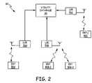
- FIG. 2illustrates a wireless meter reading system with improved gap-coverage and that is usable in a load-shedding system.
- FIG. 3is a basic schematic diagram of a front end of a low cost receiver module according to one embodiment of the invention.
- FIG. 4is a schematic diagram of another embodiment of a receiver module that is configurable to receive frequency-modulated signals for the system in FIG. 1 .
- FIG. 5is a diagram illustrating an example AMR system in which utility meter endpoints are capable of two-way communication.
- FIG. 6is a diagram illustrating examples of portable and mobile meter reading devices in the context of the AMR system of FIG. 5 .
- FIG. 7is a flow diagram illustrating an example method of operating an auxiliary transceiver according to one embodiment of the present invention.
- FIG. 8is a diagram illustrating examples of applications for various embodiments of auxiliary transceivers in the context of the example AMR system of FIG. 5 .
- the inventionis generally directed to a method and a system for collecting data from meter modules that are not read by a corresponding transceiver that is configured to read all of the meter modules in a designated area, wherein the transceiver is assigned by the central utility to the designated area. While the invention is not necessarily limited to such an application, the invention will be better appreciated using a discussion of example embodiments in such a specific context.
- a system for generating feedback to a central utility station performing selective load shedding of a plurality of electrical loadswherein each of the electrical loads is connected to a meter module adapted to measure the electricity consumed by the electrical load.
- the systemincludes a plurality of encoded reader transmitters (ERTs, or endpoints), each associated with a meter module, and at least one receiver module adapted to be communicatively connected to the central utility station and to at least one of the electrical loads via at least one endpoint.
- the receiver moduleis associated with at least one electrical load and is adapted to execute a load shed command received from the central utility station.
- the receiver modulealso receives consumption data from the meter module post execution of the load shed command and transmits the post execution consumption data to the central utility station.
- a low-cost receiveris placed in close proximity to a meter module for receiving the information; the lower the cost of the receiver the more receivers that can be distributed to improve the coverage area and the reliability read for local modules. Since the modules will be relatively close to the LCR, high sensitivity is not required.
- the LCR of the inventionis comprised of a filter electrically coupled to an amplifier and filter stages feeding a simple diode detector. The diode detector in turn is electrically coupled to a post-detection filter. This approach effectively eliminates the need for the local oscillator and mixer in most current radio designs, thereby substantially reducing the cost of the receiver. In one application the cost of the RF front end is about one-tenth the cost of the regular transceiver.
- the demodulated signalis then fed to an A/D converter that is coupled to a low-cost digital signal processor (DSP).
- DSPdecodes the signal using correlation techniques to find the endpoint's preamble and uses RSSI decoding techniques to decode the signal's data packet.
- a DSPis only one example of many microcontrollers that can be used.
- the receiveris a wide band receiver that is configured to operate without a wake up transmitter.
- the endpoint modulesare configured to be bubble-up only modules. If the modules were to be used in a fixed network type installation they could bubble at a slow rate, which would preserve battery life.
- the input of the receiveris closely coupled to power lines, which allows the use of house wiring as an antenna. While it is not appropriate to intentionally put RF energy onto power lines, such energy can nonetheless be recovered. Since there are no oscillators running in the RF front end of the receiver module there is no need to keep the receiver module off of the power lines. In addition, where a wake up transmitter is not used in connection with the receiver module there is no RF energy to couple to the power lines.
- the receiveris mountable in a collar behind the meter, in a box mounted near the breaker panel, or is configurable to be a module the size of a circuit breaker that snaps into a breaker panel. Mounting close to the electric endpoint and using the house wiring as an antenna would result in very close coupling between the receiver module and the endpoint.
- FIGS. 1 and 2there are illustrated two approaches to using the receiver module of the invention to provide gap-coverage in a system having a transceiver ( FIG. 1 ) and to substitute for the transceiver and communicate directly with the central utility station ( FIG. 2 ), respectively.
- a central reader or transceiver 20that is communicatively coupled to a utility database 30 at a central utility station.
- AMR system 10also includes a plurality of endpoints 40 A- 40 C that transmit consumption data from utility meters in the field to transceiver 20 .
- AMR system 10further includes a low cost receiver (LCR) module 50 with an antenna 52 that is positioned adjacent an endpoint 40 D that is failing to have its data transmitted to the central utility station.
- LCRlow cost receiver
- Transceiver 20transmits consumption data to a utility station having central utility database 30 , database 30 being configured to store a unique identification code for each of the meter modules (and/or endpoints) in the system 10 .
- Consumption data that is collected by the individual endpoints 40 A- 40 Dis first transmitted to central utility database 30 via transceiver 20 .
- LCRlow cost receiver
- LCR 50is positioned adjacent to endpoint 40 D assigned the data collection error and LCR 50 transmits the data received from the endpoint 40 D to transceiver 20 .
- LCR 50is comprised of a filter followed by an amplifier coupled to filter stages feeding a diode detector. The receiver module 50 can omit a local oscillator and a mixer due to its proximity to the endpoint 40 D.
- system 60includes utility database 30 that stores identification data of the meter modules and of endpoints 80 A, 80 B 1 - 80 B 2 and 80 C in the system 60 .
- Improved gap coverageis obtained by substituting the main transceiver with the LCR modules of the invention.
- LCR 70 Atransmits consumption data received by endpoint 80 A directly to utility database 30
- LCR 70 Btransmits consumption data received by endpoints 80 B 1 and 80 B 2
- LCR 70 Ctransmits consumption data received by endpoint 80 C directly to utility database 30 , respectively.
- the LCRs 70 A- 70 Ccan transmit the consumption data via a wired or a wireless network to the utility server running database 30 .
- the transmitted signalscan be amplitude-modulated signals or frequency modulated signals, depending on the system and the LCR 70 A- 70 C configuration.
- LCR 70 A- 70 C embodimentsare described in further detail below, with reference to FIGS. 3 and 4 .
- system 60generates feedback to a central utility station 30 performing selective load shedding of a plurality of electrical loads connected to a meter module.
- Endpoints 80 A- 80 Care each associated with a corresponding meter module while at least one LCR 70 A, for example, is adapted to be communicatively coupled to the central utility station 30 .
- LCRs 70 A- 70 C associated with the electrical loadare each configured to execute a load-shed command received from the central utility station 30 and to receive consumption data from the meter module post-execution of the load shed command.
- LCRs 70 A- 70 Care adapted to transmit the post-execution consumption data to the central utility station 30 .
- LCR 70 Acooperates with the utility station 30 to perform load-shedding activities in a closed loop manner.
- a load-shed commandis sent to at least one of the electrical loads to transition from a first state (e.g., running at full power) to a second state (e.g., running at reduced power).
- electricity consumption data of the electrical load in the first stateis stored and a transition of the electrical load to the second state is initiated.
- Consumption data from the meter module connected to the electrical loadis received by LCRs 70 A- 70 C and consumption data of the first state is compared with consumption data received post initiation of the load-shed command.
- Consumption data of the second state of the electrical loadis then stored, where the consumption post load-shed initiation is less than the first state consumption data.
- the second state consumption datais then transmitted to the central utility station 30 , thereby indicating that the electrical load is in the second state and confirming the load-shed command.
- the second state for the loadis to have the load shut off or taken off line.
- a method of collecting data in an AMR system having a plurality of meter modules and transmitting the data to a central utility databasecomprises receiving via an LCR a radio frequency signal from at least one of the meter modules disposed adjacent the LCR and decoding the received radio frequency signal via a correlating technique to find a signal preamble.
- a data packet within the received radio frequency signalis decoded via a received signal strength indicator (RSSI) decoding technique and then a data transfer is initiated from the receiver module to the central utility database.
- the data transferincludes transmitting decoded data from the receiver module to the central utility database via a communications network.
- RSSIreceived signal strength indicator
- a local receiver behaving as a virtual endpointwould act as a two-way endpoint for any of the endpoints that are in its domain.
- the receiverwould only receive the standard endpoint packet but could be configured to work as a demand meter for advanced meter functionality.
- the radio, or “Home Gateway,” modulecould perform two-way functions such as disconnects and monitor the effects of load shedding. This would allow a migration path for existing installations.
- the next-generation infrastructurecould be developed from the radio up to a central utility station while today's endpoints continue to be deployed because the modules are low power devices and do not create interference with adjacent installations.
- the next requirementis to get the data out of the LCR, which could be done using a “Home Gateway” by calling out on the telephone.
- Another method of accessing the datauses standard wide area network solutions such as the 802.11 standard or Bluetooth; a proprietary RF link could also be developed for this purpose.
- This linkwould be a high power two-way link to a device like a high-powered transceiver.
- a cellular digital packet data (CDPD) modemcould also be used directly from the receiver module.
- remote load switching modulescan be controlled via a power line carrier, a short haul RF link, or a direct connection. Because the radio could be closely coupled to the electric endpoint, highly reliable reads are attainable.
- the readercould implement a virtual demand meter; the demand reset can then occur in the radio module. If the electric endpoint is a 41 series endpoint bubbling at a one second rate, for example, then the time accuracy would be within one or two seconds.
- a receiver board 102is used to receive the modulated signals, which in this example are the frequency hopping spread spectrum (FHSS) signals, through an antenna 104 .
- Receiver module 100includes a microcontroller 110 , such as an 8051 microcontroller, and a signal processor 112 , preferably a digital signal processor (DSP).
- Controller 110directs data and commands to and from DSP 112 and host computer 114 .
- DSP 112is preferably a DSP chip from TEXAS INSTRUMENTS, although other compatible DSP chips known to those skilled in the art can also be used.
- DSP 112is the mathematical calculator for the correlator and decoder, which switches in and out the attenuation of the front-end amplifier.
- Receiver 100implements a low noise amplifier 116 electrically coupled to a filter 118 that is in turn electrically coupled to a variable attenuator 120 followed by an RF amplifier 122 . This configuration brings incoming endpoint packets to the decoder. For a moderate additional cost the circuit 100 can include an FFT engine.
- a correlatorcomprises a circuit, or a processor or controller, programmed to compare the incoming stream of bits to the known values as designated in the message. In the embodiment shown in FIG. 3 , the correlator is implemented in DSP 112 .
- the correlatorgives low values of correlation until an ongoing (preferably over approximately twenty bits) match is perceived. In this case, the correlator output becomes very high. Therefore, in this embodiment of the invention, there is no guessing whether the data packet is a valid endpoint packet because the correlator enables the receiver 100 to know whether the data packet is a valid endpoint packet (within the statistical probability of a false match). Further, the receiver 100 has an accurate timing of the packet bit stream, allowing it to decode the remaining portions of the data packet in the center of each bit, which increases the number of cleanly decoded packets. With a correlator implemented as described, the receiver 100 can actually detect the presence of a valid packet below the base level of noise (commonly referred to as looking into the noise).
- LCR 100also comprises a linear (diode) detector 124 electrically coupled to a filter 126 and an analog-to-digital (A/D) converter 128 that feeds DSP 112 .
- linear detector 124is omitted and A/D converter 128 comprises a high-speed A/D converter so as to enable LCR 100 to receive and decode frequency-modulated signals.
- a low cost receiveris configured to provide the same functionality of LCR 100 while omitting the connection to a host computer and eliminating the need for a microcontroller (such as microcontroller 110 ) and the need for host computer 114 .
- receiver board 103 of FIG. 4a circuit diagram of a receiver module 101 will be described that is reconfigurable to receive FM signals.
- the primary components of receiver board 103 of FIG. 4are linear detector circuitry 162 in electrical communication with analog to digital (A/D) converters 164 , 166 connected to DSP 112 , an IF frequency generator 172 , and a mixer 174 in electrical communication with IF amplifier 176 and filter 178 .
- An RF signalis received by antenna 104 in the range of 910-920 MHZ and IF frequency generator 172 generates a frequency in the range of 840-850 MHZ in one embodiment.
- IF frequency generator 172 signalis low side injected to mixer 174 .
- an IF amplifier 176 and IF filter 178are utilized to create the 70 MHZ IF signal.
- This signalis then fed into DSP 112 after passing through high-speed A/D converter 164 and low-speed A/D converter 166 .
- High-speed A/D converter 164samples the 70 MHZ signal. This is under-sampling the signal, which is the digital equivalent of a mixer. Under-sampling translates the 70 MHZ IF to base band.
- the samplesare then fed into DSP 112 , which runs a 64-point fast Fourier transform (FFT); the 64-point FFT creates thirty-two unique frequency bins, each 256 KHZ wide, in this embodiment.
- FFTfast Fourier transform
- the components of the receiver board 103 of FIG. 4also include an RF amplifier section 170 that is comprised of a low noise amplifier (LNA) 182 in electrical communication with an RF amplifier 186 via a surface acoustic wave filter (SAW) 184 .
- LNA 182has an NF of 0.6 db, a P1 dB of 0 dBm, and an IP3 of 31 dBm.
- RF amplifier 186has an NF of 1.5 dB, gain of 15 dB, P1 dB of 0 dBm, and IP3 of 26 dBm.
- High-speed A/D converter 164is preferably a 12-bit converter operating at a rate of 16.384 MSPS, while the low-speed A/D converter 166 is a 12-bit converter that operates at a rate of 262.144 KSPS in this embodiment.
- the preferred sampling rateis eight times the data rate, in this example 262.144 kHz. This sampling is done by low-speed 12-bit A/D converter 166 electrically coupled to the RSSI (linear detector) 162 of the IF and the DSP 112 .
- RSSIlinear detector
- the correlator outputis synchronized to within one-eighth of a bit. This starts the timing for decoding the rest of the packet from this time. Decoding of the packet uses the center three quarters of each bit and the first one-eighth and the last one-eighth of each bit is discarded due to uncertainty.
- One particular advantage of this embodimentis that it enables the invention to accomplish effective data sampling at a rate less than the sampling rate dictated by the Nyquist theorem (i.e., sampling must occur at more than twice the effective data transfer rate).
- the correlatoreffectively allows the decoder to operate as a synchronous power detector for the wideband signal.
- the addition of a high-speed A/D converter 164 and a change to a higher performance DSP for a modest costallows the receiver 101 to decode endpoints as a channelized receiver.
- a primary requirement for FCC part 15.247 of the receiver hopping in synchronization with the transmittercan be addressed by using a multiple channel radio to ensure decoding an endpoint on any channel.
- Use of FFT in the disclosed receiver moduleresults in a channelized radio. Where the receiver is FCC part 15.247 compliant high-powered endpoints can be read, thereby increasing the coverage area.
- a reconfigured version of module 101is adapted to operate in a frequency-modulated (FM) signal-receiving mode.
- FM signalscan prove more robust and less susceptible to interference.
- the LCR 100 and reconfigured receiver module 101 of the inventionwould therefore further improve the coverage area and read reliability in particular applications.
- reconfigured receiver 101receives FM signals via antenna 104 , and decodes FM signals sent from the endpoints.
- linear detector 162 , low-speed A/D converter 166 , and associated components 188are omitted, leaving high-speed A/D converter 164 the only input to DSP 112 when operating in a FM signal-receiving mode.
- a receiverhas a sensitivity of around ⁇ 103 dBm, which is adequate for reading endpoints in a local area, possibly one house deep. Since the receiver is wide band it can be susceptible to interferes, however such susceptibility is reduced by reducing the sensitivity of the receiver and increasing the power of the endpoint. Other approaches include reducing the sensitivity and accepting a reduced coverage range or adding some cost by increasing the filtering to the RF front end.
- FIG. 5illustrates one example embodiment of an AMR system, which is generally indicted at 200 .
- AMR system 200includes a central utility database 202 that ultimately receives utility consumption information from the plurality of individual utility meter endpoints 204 a - 204 r (generally referred to herein as utility meter endpoints 204 ).
- Each utility meter endpoint 204includes a radio transceiver (or ERT-encoder reader transmitter) that can be communicatively coupled to the utility database 202 via an AMR communications infrastructure that includes a central transceiver (or collector) 206 .
- Central transceiver 206receives transmitted consumption information corresponding to each utility meter, converts the information into a form usable by database 202 , and forwards the information to database 202 .
- Central transceiver 206is not illustrated in FIG. 5 as communicating directly with meter endpoints 204 . However, in a related embodiment, central transceiver 206 is adapted to communicate with at least some of meter endpoints 204 . In example AMR system 200 , most of utility meter endpoints 204 communicate consumption information to central transceiver 206 via intermediate transceivers 208 a , 208 b , and 208 c (generally referred to herein as intermediate transceivers 208 ).
- intermediate transceivers 208receive consumption information in the form of RF telemetry data from utility meter endpoints 204 located within their RF communications range, and re-transmit the information to central transceiver 206 over a corresponding communications channel.
- the communications channelis a wireless RF link such that intermediate transceivers 208 operate in the nature of RF repeaters. Physically, such an embodiment can be implemented by intermediate transceivers 208 each including a highly directional antenna pointed at the central transceiver and driven by a suitable transmitter having sufficient power to ensure a desired level of transmission reliability.
- the communications channelincludes a wired network.
- Data communication from intermediate transceivers 208can be bi-directional, as represented by communication 210 a between intermediate transceiver 208 a and central transceiver 206 ; or unidirectional, as represented by communication 210 b from intermediate transceiver 208 b to the central transceiver 206 . Also, communication can be relayed from one intermediate transceiver 208 c to another intermediate transceiver 208 b , and ultimately to central transceiver 206 , as represented by communication 210 c between intermediate transceivers 208 c and 208 b , and communication 210 b from intermediate transceiver 208 b to central transceiver 206 .
- Each intermediate transceiver 208is installed in a fixed location and has a limited communications range for communicating with utility meter endpoints. Therefore, each intermediate transceiver is capable of communicating only with utility meter endpoints located in its coverage area. As illustrated in FIG. 5 , intermediate transceivers 208 a , 208 b , and 208 c have coverage areas 209 a , 209 b , and 209 c , respectively. Together, intermediate transceivers 208 a , 208 b , and 208 c service a principal coverage area generally indicated at 209 . Intermediate transceivers 208 have high-capacity, high sensitivity RF receivers.
- each intermediate transceiver 208is capable of communicating with, or servicing, hundreds or even thousands of utility meter endpoints in its corresponding coverage area. Examples of communications between utility meter endpoints 204 and intermediate transceivers 208 are illustrated in FIG. 5 and generally indicated at 205 . For instance, utility meter endpoint 204 a communicates with intermediate transceiver via communications link or signal 205 a.
- Coverage areas 209 a , 209 b , and 209 chave overlapping portions, such as the coverage area portions that include utility meter endpoints 204 b , 204 c , and 204 i .
- Each of these utility meter endpointsis within communications range of more than one intermediate transceiver 208 , and indeed communicates with more than one intermediate transceiver 208 .
- utility meter endpoint 204 bcommunicates with intermediate transceiver 208 a via communications link 205 b 1 , and with intermediate transceiver 208 b via communications link 205 b 2 .
- utility meter endpoint 204 ccommunicates with intermediate transceiver 208 a via communications link 205 c 1 , and with intermediate transceiver 208 b via communications link 205 c 2 ; and utility meter endpoint 204 i communicates with intermediate transceiver 208 a via communications link 205 i 1 , and with intermediate transceiver 208 c via communications link 205 i 2 .
- each of the intermediate transceivers 208is unaware of message duplication within the system.
- each intermediate transceiver 208processes the message in its usual manner, and forwards the utility meter information to central transceiver 206 and database 202 , which is ultimately responsible for sorting out redundant units of information.
- This characteristic of example AMR system 200permits the use of additional, and potentially duplicative, intermediate-level transceivers.
- each utility meter endpoint 204can use unidirectional communication, such as the communications link 2051 from utility meter endpoint 2041 to intermediate transceiver 208 c , or bidirectional, such as communication link 205 m between utility meter endpoint 204 m and intermediate transceiver 208 c . Because the communications modules in the utility meter endpoints 204 are typically battery powered, it is desirable for the AMR system to minimize the number of transmissions required for the utility meter endpoints 204 to transmit their consumption information.
- utility meter endpoints 204utilize an infrequent bubble-up mode of occasional data transmission where a utility meter automatically wakes up according to a random, quasi-random, or predetermined time interval and begins transmitting its telemetry-gathered data.
- Each communication associated with a bubble-up eventcan itself be either unidirectional or bi-directional.
- the flow of informationis usually from the utility meter endpoint 204 to the corresponding intermediate transceiver 208 , such that the data bits originating at the intermediate transceiver 208 and received by utility meter endpoint 204 are used for implementing the transport layer protocol (for example, frame preamble bits, parity bits, acknowledgement frames, etc.).
- bidirectional communicationsare utilized to transmit information from the AMR system infrastructure to one or more utility meter endpoints 204 .
- bi-directional communicationsare used to prompt one or more utility meter endpoints to initiate data transfer of consumption information (or metered data).
- utility meter endpoints 204are capable of operating in one or more differing modes, such as in a bubble-up mode at certain times, and in a prompt-response (or wake-up) mode at other times.
- one of the utility meter endpoints 204 that is receptive to inbound communicationsincludes low-power intermittently-operating receiver circuitry for detecting the presence of a signal having predefined properties characteristic of an inbound communication addressed to a specific meter endpoint or to a group of meters to which that specific meter endpoint (or targeted endpoint) belongs. When such a signal is detected, the receiver circuitry causes the utility meter endpoint to power the receiver circuitry for a sufficient time to receive and decode the inbound communication.
- a utility meter endpoint 204operates intermittently in a signal detect mode for several milliseconds every 10-20 seconds. Between detection operations, the circuitry is in an extremely low-power-consuming standby mode. In one embodiment, the low-cost receiver circuitry described above with respect to FIG. 4 is utilized in each utility meter endpoint 204 .
- utility meter endpoints 204are capable of bubble-up, as well as prompt-response or wake-up modes of communication.
- utility meter endpoints 204typically operate in a bubble-up mode; however, the diversity of available operating modes permits the AMR system to be highly adaptable to any changing operating requirements or conditions.
- utility meter endpoint 204 goccasionally transmits its consumption information to intermediate transceiver 208 b via communication link 205 g , which occurs at random variations about a predetermined interval.
- the utility providermay wish to communicate with utility meter endpoint 204 g at an additional instance.
- FIG. 6illustrates examples of communications devices that are not a part of the infrastructure of AMR system 200 .
- a portable communicator 212provides a way for a human meter reader or technician to communicate in close proximity with utility meter endpoint 204 g at a desired time.
- Portable communicator 212initiates RF communication 213 a by transmitting a message, in response to which utility meter endpoint 204 g wakes up and transmits a reply message.
- portable communicator 212can be used, for example, to read consumption or other information from utility meter endpoint 204 g , or to reconfigure utility meter endpoint 204 g .
- Portable communicator 212can relay information received from utility meter endpoint 204 g to central transceiver 206 and utility database 202 via communication link or signal 215 to intermediate transceiver 208 b , which in turn is relayed via communication 210 b from intermediate transceiver 208 b to central transceiver 206 .
- portable communicator 212is a human-operated, battery-powered device and is typically not adapted for long-term automatic operation (i.e., without human intervention) such as equipment typically used in fixed AMR networks.
- Utility personnelmay also operate a mobile communicator 214 , also illustrated in FIG. 6 , which can initiate RF communications with a utility meter endpoint, such as utility meter endpoint 204 h , and later transfer information obtained from the meter endpoint to utility database 202 .
- mobile communicator 214is mounted on a street vehicle and coupled to a portable data collector. Data received by mobile communicator 214 and collected by the data collector can later be transferred to utility database 202 via a data transfer transmission 217 .
- portable communicator 212 and mobile communicator 214are designed to operate at a relatively close range to the utility meter endpoints with which communicators 212 , 214 are communicating, their receiver circuitry can be of a type that has low sensitivity and a low cost.
- the principal coverage area 209 of example AMR system 200has a finite outer limit.
- Coverage area 209also has gaps 216 and 218 in coverage.
- Gap 216is a void within coverage area 209 b , and is therefore an area outside of the principal coverage area 209 .
- Gap 218is outside the boundary of coverage areas 209 a and 209 b at a location where the boundaries have failed to overlap.
- Utility meters 204 e , 204 f , 204 j , 204 k , 204 n , 204 p , 204 r , and 204 qare all located outside of principal coverage area 209 , and cannot be serviced by the installed principal infrastructure that includes intermediate transceivers 208 .
- portable communicator 212 and mobile communicator 214FIG. 6
- one or more low-cost auxiliary transceiverssuch as auxiliary transceivers 220 a , 220 b , 220 c , 220 d , and 220 e illustrated in FIG. 8 (generally referred to herein as auxiliary transceivers 220 ) can be installed to supplement the communications infrastructure of AMR system 200 to provide communications service for utility meter endpoints located outside all of coverage area 209 boundaries, or located in a coverage gap.
- An auxiliary transceiver 220is similar in principle to the LCR embodiments described above in that it can be used as a communications repeater for extending or improving communications coverage in an AMR system.
- Each auxiliary transceiver 220includes at least one radio transceiver and at least one antenna for communicating with utility meter endpoints 204 , and with the AMR system communications infrastructure. Each auxiliary transceiver 220 also includes a CPU that governs operation of the auxiliary transceiver. In one embodiment, the transmission to the AMR communications infrastructure is directed to a nearby one or more intermediate transceivers 208 . In an example of the AMR system operation, each auxiliary transceiver 220 communicates with utility meter endpoints 204 that are located within its auxiliary coverage area, wirelessly receives their consumption and other information destined ultimately to utility database 202 , and wirelessly transmits the information to the AMR communications infrastructure via one or more intermediate transceivers 208 .
- Auxiliary transceiver 220differs from the LCR embodiments described above in that certain embodiments have features and operability that enable auxiliary transceiver 220 to interface with utility meter endpoints having two-way communications capabilities, and utilize this ability to operate with sufficiently low power consumption to enable operation without externally-supplied power.
- auxiliary transceiver 220is powered by at least one battery that is on-board, or integrally housed with the auxiliary transceiver. The use of on-board power greatly facilitates locating and installing the auxiliary transceiver in a preferred field location.
- a battery-powered auxiliary transceiver 220can operate for up to ten years without maintenance or human intervention.
- An auxiliary transceiver 220can be installed without having to connect to AC mains or other externally supplied power. Avoiding connection to AC power provides substantial savings in installation costs, makes possible installations in locations where AC power is unavailable, saves the cost of electrical hardware needed to make the electrical connections, and saves the cost of electronic hardware needed to condition and convert the mains power into a form suitable for powering the various circuitry.
- on-board battery poweris supplemented by solar power cells.
- FIG. 7illustrates an example operating sequence 300 of one example embodiment of an auxiliary transceiver.
- the auxiliary transceiveris preconfigured and installed in a suitable location to service utility meter endpoints 204 that are outside of coverage area 209 .
- the pre-configurationincludes programming one or more assigned RF channels, the time period between automatic activations, and the duration of each automatic activation.
- the auxiliary transceiverself-activates and transmits, or broadcasts, a prompting signal on its assigned RF channel.
- the promptincludes a wakeup sequence of bits to which utility meter endpoints respond by entering an active mode of communication.
- the promptcan also include a command and control frame according to the system communication protocol.
- the promptis a fixed sequence that does not vary due to any potentially changing external factors or circumstances.
- the prompting signalincludes an indication that the prompting signal originates from an auxiliary transceiver, and only those utility meter endpoint that are configured to respond to prompts from auxiliary transceivers, respond to the prompt.
- utility meter endpointsare each assigned to at least one communications group; and the prompting signal includes a communications group ID. Only those utility meter endpoints that have a communications group membership corresponding to the group ID in the prompt, respond.
- the auxiliary transceiveractivates its receiver circuitry by exiting a low-power standby mode, and listens for a pre-configured time duration for any transmissions responsive to the broadcast prompt.
- the auxiliary transceiverreceives them, and stores them in memory at 310 .
- the auxiliary transceiverpauses. In one embodiment, the pause is for a random time duration not exceeding 10 minutes. In one embodiment, during the pause, the auxiliary transceiver energizes its transmitter circuitry in preparation for sending the received information to the AMR system infrastructure. At 314 , the auxiliary transceiver retrieves the first stored message from memory, transmits the message to an intermediate transceiver of the AMR system, and deletes the message from its memory. In this embodiment, the transmitted message includes additional forward error correction or other suitable transport layer improvement. In a related embodiment, the transmission by the auxiliary transceiver is in a one-way communications mode, in which the auxiliary transceiver does not require any communication from any intermediate transceiver.
- the communications between the auxiliary transceiver and the intermediate transceiverare in a 1.5-way communication mode, in which the auxiliary transceiver requires some degree of responsiveness from the auxiliary transceiver, such as frame receipt acknowledgements (ACKs).
- ACKsframe receipt acknowledgements
- communications between the auxiliary transceiver and the intermediate transceiverare in a two-way communication mode, in which the auxiliary transceiver transmits endpoint information in response to prompting signals from the intermediate transceiver that are directed to utility meter endpoints and seek endpoint data.
- the auxiliary transceiverretrieves those messages in sequence, and transmits each message ( 318 ) in the same manner as described above at 314 . After all messages have been sent, the auxiliary transceiver enters a low-power standby mode and counts down until the next activation cycle ( 320 , 322 ).
- auxiliary transceiver 220is in a low power standby mode for over 50% of the time.
- auxiliary transceiver 220can operate in a low power mode more than 99% of the time, and operate in active receiving, transmitting, and processing modes the remaining 1% of the time.
- active operationoccurs intermittently, at time intervals similar to those associated with bubble-up events of utility meter endpoints 204 .
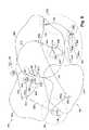
- FIG. 8illustrates several example applications for auxiliary transmitters 220 in the context of the above-described example AMR system 200 .
- Auxiliary transceiver 220 ahas been installed in coverage area 209 a such that its auxiliary coverage area 222 a (represented by a dotted line circumscribing auxiliary transceiver 220 a ) extends into gap 218 sufficiently to provide radio communications with utility meter endpoints 204 e and 204 f .
- Auxiliary transceiver 220 aalso communicates with the AMR infrastructure, as indicated at communications 226 a between auxiliary transceiver 220 a and intermediate transceiver 208 a .
- auxiliary transceiver 220 ais located within coverage area 209 a , its radio transceiver can have the same capabilities as the mass-produced radio transceivers included as part of utility meter endpoints 204 .
- One advantage that can be realizedis low cost of communications hardware in the auxiliary transceivers.
- auxiliary transceiver 220 ahas the same radio communications hardware as a utility meter endpoint 204 .
- auxiliary transceiver 220 acan have the same circuit card subassembly as the one installed in the utility meter endpoints, but different embedded software/firmware.
- Auxiliary transceiver 220 acommunicates wirelessly with utility meter endpoints 204 d , 204 e , and 204 f as respectively indicated at communications 224 d , 224 e , and 224 f .
- auxiliary transceiver 220 abroadcasts an modulated RF prompting signal directed generally at utility meter endpoints 204 located in its area of coverage 222 a .
- each promptis broadcast according to a predetermined time interval, plus or minus a random time interval.
- Utility meter endpoints 204 d , 204 e , and 204 feach respond to the prompt by transmitting their consumption and other information destined for utility database 202 .
- Utility meter endpoints 204transmit their information according to a slotted ALOHA or other suitable mode of transmission.
- auxiliary transceiver 220 areceives each utility meter's information and stores it for later transmission.
- auxiliary transceiver 220 areceives each utility meter's information and immediately transmits it to the AMR communications infrastructure.
- One example communications protocol used for such communicationsis disclosed in U.S. application having Ser. No. 10/915,706, filed on Aug. 10, 2004, entitled “Data Communications Protocol in an Automatic Meter Reading System,” which is herein incorporated by reference in its entirety.
- Auxiliary transceiver 220 atransmits the information obtained from each of the utility meter endpoints 204 d , 204 e , 204 f to the AMR communications infrastructure via communications link 226 a , which are received by intermediate transceiver 208 a . Communications from auxiliary transceivers 220 to the AMR communications infrastructure are generally referred to herein as communications 226 . In one embodiment, transmissions of data communications 226 that are transmitted by auxiliary transceiver 220 a are sent according to an ALOHA mode of transmission.
- data communications 226include separate, discrete transmissions, each corresponding to an individual utility meter's consumption data.
- data communications 226 ainclude three discrete transmissions separated in time and respectively corresponding to each of utility meter endpoints 204 d , 204 e , and 204 f .
- each discrete transmission of communications 226is in the same format as the bubbling-up transmissions from utility meter endpoints 204 .
- communications 226include separate, discrete transmissions, each corresponding to an individual utility meter's data, but each transmission is reformatted to optimize data transmission to intermediate transceiver 208 .
- each transmissioncan be encoded according to a Bose-Chaudhuri-Hochquenghem (BCH) scheme.
- BCHBose-Chaudhuri-Hochquenghem
- each intermediate transceiver 208is preconfigured to receive and process transmissions encoded in this format.
- the transmissionscan utilize a Manchester-encoding scheme.
- communications 226are in a single, condensed, transmission.
- One benefit of condensing the informationis a realization of energy savings relative to transmitting the same information in an uncondensed format.
- the intermediate transceiversare configured to handle such communications from other intermediate transceivers 208 (and auxiliary transceivers 220 ), in addition to handling communications with utility meter endpoints 204 .
- Auxiliary coverage area 222 aincludes utility meter endpoints 204 e and 204 f that are in coverage gap 218 , as well as utility meter endpoint 204 d that is also located within coverage area 209 a .
- Utility meter endpoint 204 dcommunicates information to intermediate transceiver 208 a via communication 205 d which, in one embodiment, is transmitted according to a bubble-up scheme.
- intermediate transceiver 208does nothing to address the issue of duplicity, and instead forwards each communication to the central transceiver in the usual manner as if the duplicative communications corresponded to different utility meters.
- utility database 202operates on each of the received communications to sort out the redundant duplicative sets of meter data based on the information contained in each communication, such as a tag identifying the specific utility meter and time stamp. In other embodiments, the sorting takes place at intermediate transceiver 208 , or at central transceiver 206 .
- Auxiliary transceiver 220 bis located in coverage gap 216 in order to provide communications service to utility meter endpoint 204 j .
- Auxiliary transceiver 220 bhas a coverage area 222 b that is sufficient to cover the entire coverage gap 216 .
- auxiliary transceiver 220 bis itself located outside of coverage area 209 b .
- auxiliary transceiver 220 bcan be adapted to communicate at a greater range with intermediate transceiver 208 b , as compared with a typical utility meter endpoint 204 .
- installed auxiliary transceiver 220 bincludes a high-gain directional antenna that is pointed at intermediate transceiver 208 b .
- auxiliary transceiver 220 bis installed on a high pole or tower to avoid obstructions that can affect electromagnetic wave propagation.
- auxiliary transceiver 220 bhas a more powerful RF transmitter amplifier circuit compared to the transmitter amplifier circuit of a typical utility meter endpoint 204 .
- Auxiliary transceiver 220 cis installed to extend AMR communication system coverage beyond the outside boundary of coverage area 209 in order to provide service to utility meter endpoint 204 k .
- Auxiliary transceiver 220 ceffectively extends AMR communications system coverage to include auxiliary coverage area 222 c .
- auxiliary transceiver 220 cis also configured to communicate with more than one intermediate transceiver to ensure reliable communications with the AMR system communications infrastructure. As illustrated in FIG. 8 , auxiliary transceiver 220 c communicates with intermediate transceiver 208 a via communications 226 c 1 , and with intermediate transceiver 208 c via communications link 226 c 2 .
- auxiliary transceiver 220 cincludes an omni-directional antenna and a sufficiently powerful transmitter to reach the intermediate transceivers 208 a and 208 c .
- auxiliary transceiver 220 cincludes transmitter circuitry driving two distinct high-gain directional antennas, each directed at a corresponding intermediate transceivers 208 .
- auxiliary transceiver 220 dis used to extend communications service to utility meter endpoints 204 n , 204 p , 204 q , and 204 r , which are all located outside of coverage area 209 .
- Auxiliary transceiver 220 dprovides an auxiliary coverage area 222 d that includes these utility meter endpoints.
- Auxiliary transceiver 220 dis also outside of coverage area 209 and, unlike auxiliary transceiver 220 c discussed above; auxiliary transceiver 220 d is not within communications range of any intermediate transceiver 208 .
- auxiliary transceiver 220 eis located such that it is within communications range of intermediate transceiver 208 b as well as within communications range of auxiliary transceiver 220 d . As indicated in FIG. 8 , auxiliary transceiver 220 e provides an auxiliary coverage area 222 e that includes auxiliary transceiver 220 d .
- auxiliary transceiver 220 dincludes low-power intermittently operating receiver circuitry that is the same or similar to the circuitry of utility meter endpoints 204 .
- auxiliary transceiver 220 dis programmed to periodically power up, momentarily, in an attempt to detect the presence of a communication signal in a similar operating mode as described above with respect to utility meter endpoint 204 receiver low-power operation.
- auxiliary transceiver 220 etransmits a prompt according to a preconfigured periodic transmission schedule, and activates its receiver circuitry for reception of data from auxiliary transceiver 220 d for a predetermined amount of time sufficient to receive communications responsive to the prompt.
- the prompt broadcast from auxiliary transceiver 220 eis identical to a prompt to which utility meter endpoints 204 are responsive.
- auxiliary transceivers 220are configured to not respond to prompts for a predefined time after issuing a prompt themselves. This feature prevents more than one auxiliary transceiver 220 within communications range of one another from endlessly exchanging prompts.
- the promptis included in communications 226 d , and is detected by auxiliary transceiver 220 d during one of its intermittent signal detection attempts.
- auxiliary transceiver 220 dbroadcasts a utility meter prompt to utility meter endpoints 204 in its coverage area 222 d , and activates its receiver circuitry for reception of data from utility meter endpoints 204 for a predetermined amount of time sufficient to receive communications responsive to the prompt.
- the prompt broadcast from auxiliary transceiver 220 e(intended to evoke a response from another auxiliary transceiver 220 ) is identical to a prompt to which utility meter endpoints 204 are responsive, such as the prompt broadcast from auxiliary transceiver 220 d .
- auxiliary transceivers 220are configured to not respond to prompts for a predefined time after issuing a prompt themselves.
- the prompt broadcast from auxiliary transceiver 220 eincludes an indication that distinguishes it from a prompt intended to evoke a response from utility meter endpoints 204 .
- auxiliary transceivers 220 eresponds to a prompt from auxiliary transceiver 220 d intended for utility meter endpoints 204 by broadcasting a second prompt, to which auxiliary transceiver 220 d again responds.
- Each of utility meter endpoints 204 within area of coverage 222 dresponds to the prompt issued by auxiliary transceiver 220 d by transmitting its consumption and other information according to a predefined protocol, such as slotted ALOHA mode.
- Auxiliary transceiver 220 dreceives each utility meter's data, and transmits each set of data to auxiliary transceiver 220 e .
- auxiliary transceiver 220 dtransmits each set of utility meter endpoint 204 data individually, and in the same format as in which the data was received from the corresponding utility meter endpoint 204 .
Landscapes
- Engineering & Computer Science (AREA)
- Computer Networks & Wireless Communication (AREA)
- Physics & Mathematics (AREA)
- General Physics & Mathematics (AREA)
- Selective Calling Equipment (AREA)
- Mobile Radio Communication Systems (AREA)
- Arrangements For Transmission Of Measured Signals (AREA)
Abstract
Description
Claims (44)
Priority Applications (2)
| Application Number | Priority Date | Filing Date | Title |
|---|---|---|---|
| US11/105,663US7417557B2 (en) | 2003-05-07 | 2005-04-14 | Applications for a low cost receiver in an automatic meter reading system |
| PCT/US2006/014140WO2006113472A1 (en) | 2005-04-14 | 2006-04-14 | Receiver for an automated meter reading system |
Applications Claiming Priority (3)
| Application Number | Priority Date | Filing Date | Title |
|---|---|---|---|
| US46855003P | 2003-05-07 | 2003-05-07 | |
| US10/838,165US7230972B2 (en) | 2003-05-07 | 2004-05-03 | Method and system for collecting and transmitting data in a meter reading system |
| US11/105,663US7417557B2 (en) | 2003-05-07 | 2005-04-14 | Applications for a low cost receiver in an automatic meter reading system |
Related Parent Applications (1)
| Application Number | Title | Priority Date | Filing Date |
|---|---|---|---|
| US10/838,165Continuation-In-PartUS7230972B2 (en) | 2003-05-07 | 2004-05-03 | Method and system for collecting and transmitting data in a meter reading system |
Publications (2)
| Publication Number | Publication Date |
|---|---|
| US20050179561A1 US20050179561A1 (en) | 2005-08-18 |
| US7417557B2true US7417557B2 (en) | 2008-08-26 |
Family
ID=37115473
Family Applications (1)
| Application Number | Title | Priority Date | Filing Date |
|---|---|---|---|
| US11/105,663Expired - LifetimeUS7417557B2 (en) | 2003-05-07 | 2005-04-14 | Applications for a low cost receiver in an automatic meter reading system |
Country Status (2)
| Country | Link |
|---|---|
| US (1) | US7417557B2 (en) |
| WO (1) | WO2006113472A1 (en) |
Cited By (40)
| Publication number | Priority date | Publication date | Assignee | Title |
|---|---|---|---|---|
| US20070222581A1 (en)* | 2005-10-05 | 2007-09-27 | Guardian Networks, Inc. | Method and System for Remotely Monitoring and Controlling Field Devices with a Street Lamp Elevated Mesh Network |
| US20070237247A1 (en)* | 2006-04-06 | 2007-10-11 | Alcatel Lucent | Method of reducing a peak to average power ratio of a modulated signal |
| US20080114811A1 (en)* | 2006-11-13 | 2008-05-15 | Lutron Electronics Co., Inc. | Method of communicating a command for load shedding of a load control system |
| US20080186200A1 (en)* | 2007-02-02 | 2008-08-07 | Kelly Laughlin-Parker | High power AMR transmitter with data profiling |
| US20080225453A1 (en)* | 2007-03-16 | 2008-09-18 | Hansder Engineering Co., Ltd. | Breaker control system using power frequency carrier |
| US20080249969A1 (en)* | 2007-04-04 | 2008-10-09 | The Hong Kong University Of Science And Technology | Intelligent agent for distributed services for mobile devices |
| US20090287838A1 (en)* | 2002-11-18 | 2009-11-19 | Seyamak Keyghobad | Method and apparatus for inexpensively monitoring and controlling remotely distributed appliances |
| US20090309755A1 (en)* | 2006-05-04 | 2009-12-17 | Capstone Mobile Techologies Llc | System and method for remotely monitoring and controlling a water meter |
| US20100007521A1 (en)* | 2005-09-09 | 2010-01-14 | Itron, Inc. | Rf meter reading system |
| US20100265095A1 (en)* | 2009-04-20 | 2010-10-21 | Itron, Inc. | Endpoint classification and command processing |
| US20120053902A1 (en)* | 2006-09-15 | 2012-03-01 | Itron, Inc. | Distributing metering responses for load balancing an amr network |
| US20120131100A1 (en)* | 2010-11-23 | 2012-05-24 | General Electric Company | Data collection from utility meters over advanced metering infrastructure |
| US8437883B2 (en) | 2009-05-07 | 2013-05-07 | Dominion Resources, Inc | Voltage conservation using advanced metering infrastructure and substation centralized voltage control |
| US8660134B2 (en) | 2011-10-27 | 2014-02-25 | Mueller International, Llc | Systems and methods for time-based hailing of radio frequency devices |
| US8690117B2 (en) | 2006-05-04 | 2014-04-08 | Capstone Metering Llc | Water meter |
| US20140169152A1 (en)* | 2012-12-17 | 2014-06-19 | Itron, Inc. | Intelligent Network Operation |
| US8823509B2 (en) | 2009-05-22 | 2014-09-02 | Mueller International, Llc | Infrastructure monitoring devices, systems, and methods |
| US8833390B2 (en) | 2011-05-31 | 2014-09-16 | Mueller International, Llc | Valve meter assembly and method |
| US8842712B2 (en) | 2011-03-24 | 2014-09-23 | Gregory C. Hancock | Methods and apparatuses for reception of frequency-hopping spread spectrum radio transmissions |
| US8855569B2 (en) | 2011-10-27 | 2014-10-07 | Mueller International, Llc | Systems and methods for dynamic squelching in radio frequency devices |
| US8931505B2 (en) | 2010-06-16 | 2015-01-13 | Gregory E. HYLAND | Infrastructure monitoring devices, systems, and methods |
| US9202362B2 (en) | 2008-10-27 | 2015-12-01 | Mueller International, Llc | Infrastructure monitoring system and method |
| US9325174B2 (en) | 2013-03-15 | 2016-04-26 | Dominion Resources, Inc. | Management of energy demand and energy efficiency savings from voltage optimization on electric power systems using AMI-based data analysis |
| US9354641B2 (en) | 2013-03-15 | 2016-05-31 | Dominion Resources, Inc. | Electric power system control with planning of energy demand and energy efficiency using AMI-based data analysis |
| US9367075B1 (en) | 2013-03-15 | 2016-06-14 | Dominion Resources, Inc. | Maximizing of energy delivery system compatibility with voltage optimization using AMI-based data control and analysis |
| US9400192B1 (en)* | 2004-11-16 | 2016-07-26 | Floyd Stanley Salser, JR. | Universial AMR system |
| US9494249B2 (en) | 2014-05-09 | 2016-11-15 | Mueller International, Llc | Mechanical stop for actuator and orifice |
| US20170005690A1 (en)* | 2014-08-14 | 2017-01-05 | RG5 Meter Company, (dba RG-3) | Universal receiver |
| US20170003142A1 (en)* | 2004-11-16 | 2017-01-05 | Roger Allcorn | Amr system with fly-by mode |
| US9563218B2 (en) | 2013-03-15 | 2017-02-07 | Dominion Resources, Inc. | Electric power system control with measurement of energy demand and energy efficiency using t-distributions |
| US9565620B2 (en) | 2014-09-02 | 2017-02-07 | Mueller International, Llc | Dynamic routing in a mesh network |
| US9847639B2 (en) | 2013-03-15 | 2017-12-19 | Dominion Energy, Inc. | Electric power system control with measurement of energy demand and energy efficiency |
| US20180203048A1 (en)* | 2013-12-09 | 2018-07-19 | Dataflyte, Inc. | Airborne Data Collection |
| US10180414B2 (en) | 2013-03-15 | 2019-01-15 | Mueller International, Llc | Systems for measuring properties of water in a water distribution system |
| US20190045281A1 (en)* | 2017-08-07 | 2019-02-07 | Thomas Meek | Low power, high redundancy point-to-point telemetry system |
| US20200059865A1 (en)* | 2017-08-29 | 2020-02-20 | Comcast Cable Communications, Llc | Systems and methods for using a mobile gateway in a low power wide area network |
| US10609223B2 (en)* | 2018-08-31 | 2020-03-31 | Neptune Technology Group Inc. | Multi-wireless access service and repeater service of automated meter reading system |
| US10732656B2 (en) | 2015-08-24 | 2020-08-04 | Dominion Energy, Inc. | Systems and methods for stabilizer control |
| US11041839B2 (en) | 2015-06-05 | 2021-06-22 | Mueller International, Llc | Distribution system monitoring |
| US11725366B2 (en) | 2020-07-16 | 2023-08-15 | Mueller International, Llc | Remote-operated flushing system |
Families Citing this family (29)
| Publication number | Priority date | Publication date | Assignee | Title |
|---|---|---|---|---|
| US7385524B1 (en) | 2001-09-21 | 2008-06-10 | James Robert Orlosky | Automated meter reading, billing and payment processing system |
| US7230972B2 (en)* | 2003-05-07 | 2007-06-12 | Itron, Inc. | Method and system for collecting and transmitting data in a meter reading system |
| US20050237959A1 (en)* | 2004-04-26 | 2005-10-27 | Christopher Osterloh | Mobile automatic meter reading system and method |
| US7079962B2 (en)* | 2004-10-20 | 2006-07-18 | Itron, Inc. | Automated utility meter reading system with variable bandwidth receiver |
| US8350717B2 (en)* | 2006-06-05 | 2013-01-08 | Neptune Technology Group, Inc. | Fixed network for an automatic utility meter reading system |
| US20080052019A1 (en)* | 2006-08-25 | 2008-02-28 | Brennan W J | Compact Data Transmission Protocol for Electric Utility Meters |
| US7843834B2 (en)* | 2006-09-15 | 2010-11-30 | Itron, Inc. | Use of minimal propagation delay path to optimize a mesh network |
| DE602007001228D1 (en)* | 2007-02-22 | 2009-07-16 | Actaris Sas | Connection method for remote counting of meters |
| EP1962060A1 (en)* | 2007-02-22 | 2008-08-27 | Actaris SAS | Link-up method for remote meter reading |
| US20080219210A1 (en)* | 2007-03-09 | 2008-09-11 | Elster Electricity, Llc | Reconfigurable mobile mode and fixed network mode endpoint meters |
| US20090052417A1 (en)* | 2007-08-24 | 2009-02-26 | Kabushiki Kaisha Toshiba | Wireless communication device, wireless communication method, and wireless communication system |
| US8368554B2 (en)* | 2007-12-18 | 2013-02-05 | Elster Electricity Llc | System and method for collecting information from utility meters |
| US20090303975A1 (en)* | 2008-06-05 | 2009-12-10 | Texas Instruments Incorporated | Method and system for wireless coexistence |
| US8188886B2 (en)* | 2008-07-30 | 2012-05-29 | Badger Meter, Inc. | Method and system for controlling path redundancy in the acquisition of utility meter data |
| US8531311B2 (en)* | 2009-01-29 | 2013-09-10 | Itron, Inc. | Time-divided communications in a metering system |
| CA2756944A1 (en)* | 2009-03-27 | 2010-09-30 | The Research Foundation Of State University Of New York | Automated meter reading system and energy conservation method using same |
| US8269650B2 (en) | 2010-04-14 | 2012-09-18 | Itron, Inc. | Meter right sizing |
| CN102184630A (en)* | 2011-05-09 | 2011-09-14 | 广州从兴电子开发有限公司 | Data acquisition concentrator and data acquisition method |
| US9106365B1 (en)* | 2011-12-22 | 2015-08-11 | Landis+Gyr Technologies, Llc | Time-keeping between devices using power distribution line communications |
| JP5414847B2 (en)* | 2012-07-04 | 2014-02-12 | 日本瓦斯株式会社 | Meter reading assignment system and meter reading assignment method |
| US10679131B2 (en) | 2012-07-12 | 2020-06-09 | Eaton Intelligent Power Limited | System and method for efficient data collection in distributed sensor measurement systems |
| US9644991B2 (en)* | 2012-10-01 | 2017-05-09 | Cooper Technologies Company | System and method for support of one-way endpoints in two-way wireless networks |
| JP5583830B1 (en)* | 2013-09-27 | 2014-09-03 | 日本瓦斯株式会社 | LP gas meter pointer value input check system and method |
| US9251700B2 (en)* | 2013-10-28 | 2016-02-02 | Smartlabs, Inc. | Methods and systems for powerline and radio frequency communications |
| US9699708B2 (en) | 2014-01-17 | 2017-07-04 | Cooper Technologies Company | Dynamically-selectable multi-modal modulation in wireless multihop networks |
| GB201504450D0 (en)* | 2015-03-17 | 2015-04-29 | Linde Ag | A communication system |
| FR3068163B1 (en)* | 2017-06-23 | 2019-12-20 | Diehl Metering Sas | METHOD AND SYSTEM FOR COLLECTING DATA PROVIDED BY SENSORS |
| US10594441B2 (en)* | 2018-04-23 | 2020-03-17 | Landis+Gyr Innovations, Inc. | Gap data collection for low energy devices |
| CN112492571B (en)* | 2020-11-30 | 2022-09-13 | 沈畅 | Low-power-consumption communication method and system for wireless meter reading |
Citations (63)
| Publication number | Priority date | Publication date | Assignee | Title |
|---|---|---|---|---|
| US3919640A (en) | 1974-11-08 | 1975-11-11 | Northern Illinois Gas Co | Simultaneous analog and digital data transfer |
| US4589075A (en) | 1983-02-23 | 1986-05-13 | Buennagel James A | Remote load data acquisition and control system for a power network |
| US4940976A (en) | 1988-02-05 | 1990-07-10 | Utilicom Inc. | Automated remote water meter readout system |
| JPH02246000A (en) | 1989-03-20 | 1990-10-01 | Nitto Kohki Co Ltd | Meter inspecting system |
| US5056107A (en) | 1990-02-15 | 1991-10-08 | Iris Systems Inc. | Radio communication network for remote data generating stations |
| JPH0576075A (en) | 1991-09-11 | 1993-03-26 | Omron Corp | Wireless meter reading device |
| US5278551A (en) | 1989-03-20 | 1994-01-11 | Nitto Kohki Co., Ltd. | Meter reading system |
| US5335246A (en) | 1992-08-20 | 1994-08-02 | Nexus Telecommunication Systems, Ltd. | Pager with reverse paging facility |
| JPH06351071A (en) | 1993-06-08 | 1994-12-22 | Ricoh Elemex Corp | Wireless meter inspection method |
| US5377232A (en) | 1992-01-09 | 1994-12-27 | Cellnet Data Systems, Inc. | Frequency synchronized bidirectional radio system |
| US5430759A (en) | 1992-08-20 | 1995-07-04 | Nexus 1994 Limited | Low-power frequency-hopped spread spectrum reverse paging system |
| US5438329A (en) | 1993-06-04 | 1995-08-01 | M & Fc Holding Company, Inc. | Duplex bi-directional multi-mode remote instrument reading and telemetry system |
| US5475867A (en) | 1992-02-06 | 1995-12-12 | Itron, Inc. | Distributed supervisory control and data acquisition system |
| US5515369A (en) | 1994-06-24 | 1996-05-07 | Metricom, Inc. | Method for frequency sharing and frequency punchout in frequency hopping communications network |
| US5519387A (en) | 1994-04-14 | 1996-05-21 | Motorola, Inc. | Utility meter assembly and remote module and mounting apparatus and assembly |
| US5528621A (en) | 1989-06-29 | 1996-06-18 | Symbol Technologies, Inc. | Packet data communication system |
| US5604768A (en) | 1992-01-09 | 1997-02-18 | Cellnet Data Systems, Inc. | Frequency synchronized bidirectional radio system |
| US5631636A (en) | 1994-03-04 | 1997-05-20 | Motorola, Inc. | Method of reducing power consumption in a remote meter reading system |
| US5661750A (en) | 1995-06-06 | 1997-08-26 | Cellnet Data Systems, Inc. | Direct sequence spread spectrum system |
| US5712867A (en) | 1992-10-15 | 1998-01-27 | Nexus 1994 Limited | Two-way paging apparatus having highly accurate frequency hopping synchronization |
| WO1998010394A1 (en) | 1996-09-06 | 1998-03-12 | Innovatec Corporation | Automatic meter reading data communication system |
| US5764158A (en) | 1995-11-20 | 1998-06-09 | Water Savers, Inc. | Meter reading data transmissiion system and method of using same |
| WO1998059427A1 (en) | 1997-06-23 | 1998-12-30 | Cellnet Data Systems, Inc. | Processing a spread spectrum signal in a frequency adjustable system |
| WO1998059445A1 (en) | 1997-06-23 | 1998-12-30 | Cellnet Data Systems, Inc. | Bandpass processing of a spread spectrum signal |
| WO1998059429A1 (en) | 1997-06-23 | 1998-12-30 | Cellnet Data Systems, Inc. | Acquiring a spread spectrum signal |
| WO1998059446A1 (en) | 1997-06-23 | 1998-12-30 | Cellnet Data Systems, Inc. | Receiving a spread spectrum signal |
| WO1998059444A1 (en) | 1997-06-23 | 1998-12-30 | Cellnet Data Systems, Inc. | Bandpass correlation of a spread spectrum signal |
| US5874903A (en) | 1997-06-06 | 1999-02-23 | Abb Power T & D Company Inc. | RF repeater for automatic meter reading system |
| US5883886A (en) | 1997-01-03 | 1999-03-16 | Motorola, Inc. | Utility meter readings on a reverse channel of a two-way paging system |
| US5892758A (en)* | 1996-07-11 | 1999-04-06 | Qualcomm Incorporated | Concentrated subscriber wireless remote telemetry system |
| US5914672A (en) | 1997-06-13 | 1999-06-22 | Whisper Communications Incorporated | System for field installation of a remote meter interface |
| JPH11304842A (en) | 1998-04-22 | 1999-11-05 | Takeshi Tsukahara | Watt-hour meter for household to transmit indicated watt-hour number by contact wireless transmitter incorporated in the watt-hour meter |
| WO1999057697A1 (en) | 1998-05-01 | 1999-11-11 | Abb Power T & D Company Inc. | Wireless area network communications module for utility meters |
| US6014089A (en) | 1996-10-28 | 2000-01-11 | Tracy Corporation Ii | Method for transmitting data using a digital control channel of a wireless network |
| US6044062A (en) | 1996-12-06 | 2000-03-28 | Communique, Llc | Wireless network system and method for providing same |
| US6061453A (en) | 1996-03-08 | 2000-05-09 | Societe D'applications Mecaniques Et Electriques De Boulogne Billancourt, Sappel | Communication system by radio connection |
| US6069571A (en) | 1995-10-06 | 2000-05-30 | Motorola, Inc. | Apparatus and method for collecting meter data |
| US6078785A (en) | 1996-10-15 | 2000-06-20 | Bush; E. William | Demand reporting of electricity consumption by radio in relays to a base station, and demand relays wattmeters so reporting over a wide area |
| US6163276A (en) | 1999-05-17 | 2000-12-19 | Cellnet Data Systems, Inc. | System for remote data collection |
| US6172616B1 (en) | 1990-02-15 | 2001-01-09 | Itron, Inc. | Wide area communications network for remote data generating stations |
| US6178197B1 (en) | 1997-06-23 | 2001-01-23 | Cellnet Data Systems, Inc. | Frequency discrimination in a spread spectrum signal processing system |
| US6181258B1 (en) | 1999-05-17 | 2001-01-30 | Cellnet Data Systems, Inc. | Receiver capable of parallel demodulation of messages |
| US6195018B1 (en) | 1996-02-07 | 2001-02-27 | Cellnet Data Systems, Inc. | Metering system |
| US6208696B1 (en) | 1997-10-07 | 2001-03-27 | Ramar Technology Limited | Low power density radio system |
| US6219655B1 (en) | 1997-09-17 | 2001-04-17 | Itron, Cin. | Method of RF-based communication |
| US6246677B1 (en) | 1996-09-06 | 2001-06-12 | Innovatec Communications, Llc | Automatic meter reading data communication system |
| WO2001055865A1 (en) | 2000-01-31 | 2001-08-02 | Telemetry Technologies, Inc. | Wireless communication enabled meter and network |
| US6300881B1 (en) | 1999-06-09 | 2001-10-09 | Motorola, Inc. | Data transfer system and method for communicating utility consumption data over power line carriers |
| WO2001078804A1 (en) | 2000-04-14 | 2001-10-25 | Aksys. Ltd. | Bottles for dialysis machines and method for automatically identifying such bottles |
| US20020071478A1 (en) | 2000-08-01 | 2002-06-13 | Cornwall Mark K. | Frequency hopping spread spectrum system with high sensitivity tracking and synchronization for frequency unstable signals |
| US20020082748A1 (en) | 2000-06-15 | 2002-06-27 | Internet Energy Systems, Inc. | Utility monitoring and control systems |
| US6430210B1 (en) | 1999-04-05 | 2002-08-06 | General Electric Company | Receiver for detecting an amplitude modulated signal insinuated on an GHM signal |
| US6437692B1 (en)* | 1998-06-22 | 2002-08-20 | Statsignal Systems, Inc. | System and method for monitoring and controlling remote devices |
| US6452986B1 (en) | 1999-05-17 | 2002-09-17 | Cellnet Data Systems, Inc. | Detector tolerant of frequency misalignment |
| US6477558B1 (en) | 1999-05-17 | 2002-11-05 | Schlumberger Resource Management Systems, Inc. | System for performing load management |
| US6538577B1 (en) | 1997-09-05 | 2003-03-25 | Silver Springs Networks, Inc. | Electronic electric meter for networked meter reading |
| US6671586B2 (en) | 2001-08-15 | 2003-12-30 | Statsignal Systems, Inc. | System and method for controlling power demand over an integrated wireless network |
| US6677862B1 (en) | 1999-05-17 | 2004-01-13 | Schlumbergersema Inc. | Transmitter tolerant to crystal variations |
| US6710721B1 (en) | 1999-10-16 | 2004-03-23 | Datamatic Inc. | Radio frequency automated meter reading device |
| US6737985B1 (en) | 1997-12-16 | 2004-05-18 | Advanced Technology Ramar Limited | Remote metering |
| US6755148B2 (en) | 2001-11-15 | 2004-06-29 | Datamatic Ltd | Dual magnetic register for a utility meter |
| US6778099B1 (en) | 1998-05-01 | 2004-08-17 | Elster Electricity, Llc | Wireless area network communications module for utility meters |
| US6856257B1 (en)* | 2002-04-12 | 2005-02-15 | Gellnet Innovations, Inc. | Data collection and metering system |
Family Cites Families (2)
| Publication number | Priority date | Publication date | Assignee | Title |
|---|---|---|---|---|
| US5896097A (en)* | 1996-03-06 | 1999-04-20 | Schlumberger Resource Management Services, Inc. | System for utility meter communications using a single RF frequency |
| US5986574A (en)* | 1997-10-16 | 1999-11-16 | Peco Energy Company | System and method for communication between remote locations |
- 2005
- 2005-04-14USUS11/105,663patent/US7417557B2/ennot_activeExpired - Lifetime
- 2006
- 2006-04-14WOPCT/US2006/014140patent/WO2006113472A1/enactiveApplication Filing
Patent Citations (70)
| Publication number | Priority date | Publication date | Assignee | Title |
|---|---|---|---|---|
| US3919640A (en) | 1974-11-08 | 1975-11-11 | Northern Illinois Gas Co | Simultaneous analog and digital data transfer |
| US4589075A (en) | 1983-02-23 | 1986-05-13 | Buennagel James A | Remote load data acquisition and control system for a power network |
| US4940976A (en) | 1988-02-05 | 1990-07-10 | Utilicom Inc. | Automated remote water meter readout system |
| US5278551A (en) | 1989-03-20 | 1994-01-11 | Nitto Kohki Co., Ltd. | Meter reading system |
| JPH02246000A (en) | 1989-03-20 | 1990-10-01 | Nitto Kohki Co Ltd | Meter inspecting system |
| US5528621A (en) | 1989-06-29 | 1996-06-18 | Symbol Technologies, Inc. | Packet data communication system |
| US6172616B1 (en) | 1990-02-15 | 2001-01-09 | Itron, Inc. | Wide area communications network for remote data generating stations |
| US5056107A (en) | 1990-02-15 | 1991-10-08 | Iris Systems Inc. | Radio communication network for remote data generating stations |
| JPH0576075A (en) | 1991-09-11 | 1993-03-26 | Omron Corp | Wireless meter reading device |
| US5604768A (en) | 1992-01-09 | 1997-02-18 | Cellnet Data Systems, Inc. | Frequency synchronized bidirectional radio system |
| US5377232A (en) | 1992-01-09 | 1994-12-27 | Cellnet Data Systems, Inc. | Frequency synchronized bidirectional radio system |
| US5475867A (en) | 1992-02-06 | 1995-12-12 | Itron, Inc. | Distributed supervisory control and data acquisition system |
| US5870426A (en) | 1992-08-20 | 1999-02-09 | Nexus 1994 Limited | Grouping of spread spectrum acknowledgement pagers to minimize transmission collisions |
| US5499266A (en) | 1992-08-20 | 1996-03-12 | Nexus 1994 Limited | Low-power frequency-hopped spread spectrum acknowledgement paging system |
| US5546422A (en) | 1992-08-20 | 1996-08-13 | Nexus 1994 Limited | Method of transmitting low-power frequency hopped spread spectrum data |
| US5430759A (en) | 1992-08-20 | 1995-07-04 | Nexus 1994 Limited | Low-power frequency-hopped spread spectrum reverse paging system |
| US5335246A (en) | 1992-08-20 | 1994-08-02 | Nexus Telecommunication Systems, Ltd. | Pager with reverse paging facility |
| US5712867A (en) | 1992-10-15 | 1998-01-27 | Nexus 1994 Limited | Two-way paging apparatus having highly accurate frequency hopping synchronization |
| US5438329A (en) | 1993-06-04 | 1995-08-01 | M & Fc Holding Company, Inc. | Duplex bi-directional multi-mode remote instrument reading and telemetry system |
| JPH06351071A (en) | 1993-06-08 | 1994-12-22 | Ricoh Elemex Corp | Wireless meter inspection method |
| US5631636A (en) | 1994-03-04 | 1997-05-20 | Motorola, Inc. | Method of reducing power consumption in a remote meter reading system |
| US5519387A (en) | 1994-04-14 | 1996-05-21 | Motorola, Inc. | Utility meter assembly and remote module and mounting apparatus and assembly |
| US5515369A (en) | 1994-06-24 | 1996-05-07 | Metricom, Inc. | Method for frequency sharing and frequency punchout in frequency hopping communications network |
| US5661750A (en) | 1995-06-06 | 1997-08-26 | Cellnet Data Systems, Inc. | Direct sequence spread spectrum system |
| US6069571A (en) | 1995-10-06 | 2000-05-30 | Motorola, Inc. | Apparatus and method for collecting meter data |
| US5764158A (en) | 1995-11-20 | 1998-06-09 | Water Savers, Inc. | Meter reading data transmissiion system and method of using same |
| US6195018B1 (en) | 1996-02-07 | 2001-02-27 | Cellnet Data Systems, Inc. | Metering system |
| US6061453A (en) | 1996-03-08 | 2000-05-09 | Societe D'applications Mecaniques Et Electriques De Boulogne Billancourt, Sappel | Communication system by radio connection |
| US5892758A (en)* | 1996-07-11 | 1999-04-06 | Qualcomm Incorporated | Concentrated subscriber wireless remote telemetry system |
| US6246677B1 (en) | 1996-09-06 | 2001-06-12 | Innovatec Communications, Llc | Automatic meter reading data communication system |
| WO1998010394A1 (en) | 1996-09-06 | 1998-03-12 | Innovatec Corporation | Automatic meter reading data communication system |
| US6078785A (en) | 1996-10-15 | 2000-06-20 | Bush; E. William | Demand reporting of electricity consumption by radio in relays to a base station, and demand relays wattmeters so reporting over a wide area |
| US6014089A (en) | 1996-10-28 | 2000-01-11 | Tracy Corporation Ii | Method for transmitting data using a digital control channel of a wireless network |
| US6249516B1 (en) | 1996-12-06 | 2001-06-19 | Edwin B. Brownrigg | Wireless network gateway and method for providing same |
| US6044062A (en) | 1996-12-06 | 2000-03-28 | Communique, Llc | Wireless network system and method for providing same |
| US5883886A (en) | 1997-01-03 | 1999-03-16 | Motorola, Inc. | Utility meter readings on a reverse channel of a two-way paging system |
| US5874903A (en) | 1997-06-06 | 1999-02-23 | Abb Power T & D Company Inc. | RF repeater for automatic meter reading system |
| US6137423A (en) | 1997-06-13 | 2000-10-24 | Whisper Communications, Inc. | System for communication with a remote meter interface |
| US5914672A (en) | 1997-06-13 | 1999-06-22 | Whisper Communications Incorporated | System for field installation of a remote meter interface |
| WO1998059446A1 (en) | 1997-06-23 | 1998-12-30 | Cellnet Data Systems, Inc. | Receiving a spread spectrum signal |
| WO1998059444A1 (en) | 1997-06-23 | 1998-12-30 | Cellnet Data Systems, Inc. | Bandpass correlation of a spread spectrum signal |
| US6047016A (en) | 1997-06-23 | 2000-04-04 | Cellnet Data Systems, Inc. | Processing a spread spectrum signal in a frequency adjustable system |
| WO1998059427A1 (en) | 1997-06-23 | 1998-12-30 | Cellnet Data Systems, Inc. | Processing a spread spectrum signal in a frequency adjustable system |
| US6178197B1 (en) | 1997-06-23 | 2001-01-23 | Cellnet Data Systems, Inc. | Frequency discrimination in a spread spectrum signal processing system |
| WO1998059445A1 (en) | 1997-06-23 | 1998-12-30 | Cellnet Data Systems, Inc. | Bandpass processing of a spread spectrum signal |
| WO1998059429A1 (en) | 1997-06-23 | 1998-12-30 | Cellnet Data Systems, Inc. | Acquiring a spread spectrum signal |
| US6538577B1 (en) | 1997-09-05 | 2003-03-25 | Silver Springs Networks, Inc. | Electronic electric meter for networked meter reading |
| US6219655B1 (en) | 1997-09-17 | 2001-04-17 | Itron, Cin. | Method of RF-based communication |
| US6208696B1 (en) | 1997-10-07 | 2001-03-27 | Ramar Technology Limited | Low power density radio system |
| US6737985B1 (en) | 1997-12-16 | 2004-05-18 | Advanced Technology Ramar Limited | Remote metering |
| JPH11304842A (en) | 1998-04-22 | 1999-11-05 | Takeshi Tsukahara | Watt-hour meter for household to transmit indicated watt-hour number by contact wireless transmitter incorporated in the watt-hour meter |
| US6778099B1 (en) | 1998-05-01 | 2004-08-17 | Elster Electricity, Llc | Wireless area network communications module for utility meters |
| WO1999057697A1 (en) | 1998-05-01 | 1999-11-11 | Abb Power T & D Company Inc. | Wireless area network communications module for utility meters |
| US6437692B1 (en)* | 1998-06-22 | 2002-08-20 | Statsignal Systems, Inc. | System and method for monitoring and controlling remote devices |
| US6430210B1 (en) | 1999-04-05 | 2002-08-06 | General Electric Company | Receiver for detecting an amplitude modulated signal insinuated on an GHM signal |
| US6163276A (en) | 1999-05-17 | 2000-12-19 | Cellnet Data Systems, Inc. | System for remote data collection |
| US6677862B1 (en) | 1999-05-17 | 2004-01-13 | Schlumbergersema Inc. | Transmitter tolerant to crystal variations |
| US6181258B1 (en) | 1999-05-17 | 2001-01-30 | Cellnet Data Systems, Inc. | Receiver capable of parallel demodulation of messages |
| US6452986B1 (en) | 1999-05-17 | 2002-09-17 | Cellnet Data Systems, Inc. | Detector tolerant of frequency misalignment |
| US6477558B1 (en) | 1999-05-17 | 2002-11-05 | Schlumberger Resource Management Systems, Inc. | System for performing load management |
| US6300881B1 (en) | 1999-06-09 | 2001-10-09 | Motorola, Inc. | Data transfer system and method for communicating utility consumption data over power line carriers |
| WO2001010070A1 (en) | 1999-07-30 | 2001-02-08 | Schlumberger Resource Management Services, Inc. | Frequency discrimination in a spread spectrum signal processing system |
| US6710721B1 (en) | 1999-10-16 | 2004-03-23 | Datamatic Inc. | Radio frequency automated meter reading device |
| WO2001055865A1 (en) | 2000-01-31 | 2001-08-02 | Telemetry Technologies, Inc. | Wireless communication enabled meter and network |
| WO2001078804A1 (en) | 2000-04-14 | 2001-10-25 | Aksys. Ltd. | Bottles for dialysis machines and method for automatically identifying such bottles |
| US20020082748A1 (en) | 2000-06-15 | 2002-06-27 | Internet Energy Systems, Inc. | Utility monitoring and control systems |
| US20020071478A1 (en) | 2000-08-01 | 2002-06-13 | Cornwall Mark K. | Frequency hopping spread spectrum system with high sensitivity tracking and synchronization for frequency unstable signals |
| US6671586B2 (en) | 2001-08-15 | 2003-12-30 | Statsignal Systems, Inc. | System and method for controlling power demand over an integrated wireless network |
| US6755148B2 (en) | 2001-11-15 | 2004-06-29 | Datamatic Ltd | Dual magnetic register for a utility meter |
| US6856257B1 (en)* | 2002-04-12 | 2005-02-15 | Gellnet Innovations, Inc. | Data collection and metering system |
Non-Patent Citations (1)
| Title |
|---|
| Flyer from Itron, "The Future is Now". |
Cited By (92)
| Publication number | Priority date | Publication date | Assignee | Title |
|---|---|---|---|---|
| US7752309B2 (en) | 2002-11-18 | 2010-07-06 | Mueller International, Inc. | Method and apparatus for inexpensively monitoring and controlling remotely distributed appliances |
| US8549131B2 (en) | 2002-11-18 | 2013-10-01 | Mueller International, Llc | Method and apparatus for inexpensively monitoring and controlling remotely distributed appliances |
| US8407333B2 (en) | 2002-11-18 | 2013-03-26 | Mueller International, Llc | Method and apparatus for inexpensively monitoring and controlling remotely distributed appliances |
| US20090287838A1 (en)* | 2002-11-18 | 2009-11-19 | Seyamak Keyghobad | Method and apparatus for inexpensively monitoring and controlling remotely distributed appliances |
| US8140667B2 (en) | 2002-11-18 | 2012-03-20 | Mueller International, Llc | Method and apparatus for inexpensively monitoring and controlling remotely distributed appliances |
| US20090319853A1 (en)* | 2002-11-18 | 2009-12-24 | Seyamak Keyghobad | Method and apparatus for inexpensively monitoring and controlling remotely distributed appliances |
| US7792946B2 (en) | 2002-11-18 | 2010-09-07 | Mueller International, Inc. | Method and apparatus for inexpensively monitoring and controlling remotely distributed appliances |
| US7783738B2 (en) | 2002-11-18 | 2010-08-24 | Mueller International, Inc. | Method and apparatus for inexpensively monitoring and controlling remotely distributed appliances |
| US20170003142A1 (en)* | 2004-11-16 | 2017-01-05 | Roger Allcorn | Amr system with fly-by mode |
| US9981731B2 (en)* | 2004-11-16 | 2018-05-29 | Roger Allcorn | AMR system with fly-by mode |
| US9400192B1 (en)* | 2004-11-16 | 2016-07-26 | Floyd Stanley Salser, JR. | Universial AMR system |
| US8390472B2 (en)* | 2005-09-09 | 2013-03-05 | Itron, Inc. | RF meter reading system |
| US20100007521A1 (en)* | 2005-09-09 | 2010-01-14 | Itron, Inc. | Rf meter reading system |
| US7817063B2 (en)* | 2005-10-05 | 2010-10-19 | Abl Ip Holding Llc | Method and system for remotely monitoring and controlling field devices with a street lamp elevated mesh network |
| US20070222581A1 (en)* | 2005-10-05 | 2007-09-27 | Guardian Networks, Inc. | Method and System for Remotely Monitoring and Controlling Field Devices with a Street Lamp Elevated Mesh Network |
| US7907588B2 (en)* | 2006-04-06 | 2011-03-15 | Alcatel Lucent | Method of reducing a peak to average power ratio of a modulated signal |
| US20070237247A1 (en)* | 2006-04-06 | 2007-10-11 | Alcatel Lucent | Method of reducing a peak to average power ratio of a modulated signal |
| US20090309755A1 (en)* | 2006-05-04 | 2009-12-17 | Capstone Mobile Techologies Llc | System and method for remotely monitoring and controlling a water meter |
| US8690117B2 (en) | 2006-05-04 | 2014-04-08 | Capstone Metering Llc | Water meter |
| US8866634B2 (en) | 2006-05-04 | 2014-10-21 | Capstone Metering Llc | System and method for remotely monitoring and controlling a water meter |
| US20120053902A1 (en)* | 2006-09-15 | 2012-03-01 | Itron, Inc. | Distributing metering responses for load balancing an amr network |
| US8494792B2 (en)* | 2006-09-15 | 2013-07-23 | Itron, Inc. | Distributing metering responses for load balancing an AMR network |
| US7747357B2 (en)* | 2006-11-13 | 2010-06-29 | Lutron Electronics Co., Inc. | Method of communicating a command for load shedding of a load control system |
| US20080114811A1 (en)* | 2006-11-13 | 2008-05-15 | Lutron Electronics Co., Inc. | Method of communicating a command for load shedding of a load control system |
| US8031049B2 (en)* | 2006-11-13 | 2011-10-04 | Lutron Electronics Co., Inc. | Method of communicating a command for load shedding of a load control system |
| US20100225452A1 (en)* | 2006-11-13 | 2010-09-09 | Lutron Electronic Co., Inc. | Method of communicating a command for load shedding of a load control system |
| US20080186200A1 (en)* | 2007-02-02 | 2008-08-07 | Kelly Laughlin-Parker | High power AMR transmitter with data profiling |
| US8217804B2 (en)* | 2007-02-02 | 2012-07-10 | Badger Meter, Inc. | High power AMR transmitter with data profiling for mobile networks |
| US20080225453A1 (en)* | 2007-03-16 | 2008-09-18 | Hansder Engineering Co., Ltd. | Breaker control system using power frequency carrier |
| US8032472B2 (en)* | 2007-04-04 | 2011-10-04 | Tuen Solutions Limited Liability Company | Intelligent agent for distributed services for mobile devices |
| US8209275B2 (en) | 2007-04-04 | 2012-06-26 | Tuen Solutions Limited Liability Company | Intelligent agent for distributed services for mobile devices |
| US20080249969A1 (en)* | 2007-04-04 | 2008-10-09 | The Hong Kong University Of Science And Technology | Intelligent agent for distributed services for mobile devices |
| US9934670B2 (en) | 2008-10-27 | 2018-04-03 | Mueller International, Llc | Infrastructure monitoring system and method |
| US10262518B2 (en) | 2008-10-27 | 2019-04-16 | Mueller International Llc | Method of disseminating monitoring information relating to contamination and corrosion within an infrastructure |
| US9202362B2 (en) | 2008-10-27 | 2015-12-01 | Mueller International, Llc | Infrastructure monitoring system and method |
| US20100265095A1 (en)* | 2009-04-20 | 2010-10-21 | Itron, Inc. | Endpoint classification and command processing |
| US8437883B2 (en) | 2009-05-07 | 2013-05-07 | Dominion Resources, Inc | Voltage conservation using advanced metering infrastructure and substation centralized voltage control |
| US8577510B2 (en) | 2009-05-07 | 2013-11-05 | Dominion Resources, Inc. | Voltage conservation using advanced metering infrastructure and substation centralized voltage control |
| US8823509B2 (en) | 2009-05-22 | 2014-09-02 | Mueller International, Llc | Infrastructure monitoring devices, systems, and methods |
| US9799204B2 (en) | 2009-05-22 | 2017-10-24 | Mueller International, Llc | Infrastructure monitoring system and method and particularly as related to fire hydrants and water distribution |
| US8931505B2 (en) | 2010-06-16 | 2015-01-13 | Gregory E. HYLAND | Infrastructure monitoring devices, systems, and methods |
| US9861848B2 (en) | 2010-06-16 | 2018-01-09 | Mueller International, Llc | Infrastructure monitoring devices, systems, and methods |
| US9849322B2 (en) | 2010-06-16 | 2017-12-26 | Mueller International, Llc | Infrastructure monitoring devices, systems, and methods |
| US20120131100A1 (en)* | 2010-11-23 | 2012-05-24 | General Electric Company | Data collection from utility meters over advanced metering infrastructure |
| US8667060B2 (en)* | 2010-11-23 | 2014-03-04 | General Electric Company | Data collection from utility meters over advanced metering infrastructure |
| US8842712B2 (en) | 2011-03-24 | 2014-09-23 | Gregory C. Hancock | Methods and apparatuses for reception of frequency-hopping spread spectrum radio transmissions |
| US8833390B2 (en) | 2011-05-31 | 2014-09-16 | Mueller International, Llc | Valve meter assembly and method |
| US10039018B2 (en) | 2011-10-27 | 2018-07-31 | Mueller International, Llc | Systems and methods for recovering an out-of-service node in a hierarchical network |
| US8855569B2 (en) | 2011-10-27 | 2014-10-07 | Mueller International, Llc | Systems and methods for dynamic squelching in radio frequency devices |
| US8660134B2 (en) | 2011-10-27 | 2014-02-25 | Mueller International, Llc | Systems and methods for time-based hailing of radio frequency devices |
| US9356831B2 (en)* | 2012-12-17 | 2016-05-31 | Itron, Inc. | Intelligent network operation |
| US20140169152A1 (en)* | 2012-12-17 | 2014-06-19 | Itron, Inc. | Intelligent Network Operation |
| US9367075B1 (en) | 2013-03-15 | 2016-06-14 | Dominion Resources, Inc. | Maximizing of energy delivery system compatibility with voltage optimization using AMI-based data control and analysis |
| US9325174B2 (en) | 2013-03-15 | 2016-04-26 | Dominion Resources, Inc. | Management of energy demand and energy efficiency savings from voltage optimization on electric power systems using AMI-based data analysis |
| US9678520B2 (en) | 2013-03-15 | 2017-06-13 | Dominion Resources, Inc. | Electric power system control with planning of energy demand and energy efficiency using AMI-based data analysis |
| US12253507B2 (en) | 2013-03-15 | 2025-03-18 | Mueller International, Llc | Systems for measuring properties of water in a water distribution system |
| US9847639B2 (en) | 2013-03-15 | 2017-12-19 | Dominion Energy, Inc. | Electric power system control with measurement of energy demand and energy efficiency |
| US9563218B2 (en) | 2013-03-15 | 2017-02-07 | Dominion Resources, Inc. | Electric power system control with measurement of energy demand and energy efficiency using t-distributions |
| US11550352B2 (en) | 2013-03-15 | 2023-01-10 | Dominion Energy, Inc. | Maximizing of energy delivery system compatibility with voltage optimization |
| US9553453B2 (en) | 2013-03-15 | 2017-01-24 | Dominion Resources, Inc. | Management of energy demand and energy efficiency savings from voltage optimization on electric power systems using AMI-based data analysis |
| US9887541B2 (en) | 2013-03-15 | 2018-02-06 | Dominion Energy, Inc. | Electric power system control with measurement of energy demand and energy efficiency using T-distributions |
| US11307190B2 (en) | 2013-03-15 | 2022-04-19 | Mueller International, Llc | Systems for measuring properties of water in a water distribution system |
| US9582020B2 (en) | 2013-03-15 | 2017-02-28 | Dominion Resources, Inc. | Maximizing of energy delivery system compatibility with voltage optimization using AMI-based data control and analysis |
| US10775815B2 (en) | 2013-03-15 | 2020-09-15 | Dominion Energy, Inc. | Electric power system control with planning of energy demand and energy efficiency using AMI-based data analysis |
| US9354641B2 (en) | 2013-03-15 | 2016-05-31 | Dominion Resources, Inc. | Electric power system control with planning of energy demand and energy efficiency using AMI-based data analysis |
| US10180414B2 (en) | 2013-03-15 | 2019-01-15 | Mueller International, Llc | Systems for measuring properties of water in a water distribution system |
| US11255835B2 (en) | 2013-03-15 | 2022-02-22 | Mueller International, Llc | Systems for measuring properties of water in a water distribution system |
| US10203315B2 (en) | 2013-03-15 | 2019-02-12 | Mueller International Llc | Systems for measuring properties of water in a water distribution system |
| US10768655B2 (en) | 2013-03-15 | 2020-09-08 | Dominion Energy, Inc. | Maximizing of energy delivery system compatibility with voltage optimization |
| US10274985B2 (en) | 2013-03-15 | 2019-04-30 | Dominion Energy, Inc. | Maximizing of energy delivery system compatibility with voltage optimization |
| US10386872B2 (en) | 2013-03-15 | 2019-08-20 | Dominion Energy, Inc. | Electric power system control with planning of energy demand and energy efficiency using AMI-based data analysis |
| US10476273B2 (en) | 2013-03-15 | 2019-11-12 | Dominion Energy, Inc. | Management of energy demand and energy efficiency savings from voltage optimization on electric power systems using AMI-based data analysis |
| US11132012B2 (en) | 2013-03-15 | 2021-09-28 | Dominion Energy, Inc. | Maximizing of energy delivery system compatibility with voltage optimization |
| US10784688B2 (en) | 2013-03-15 | 2020-09-22 | Dominion Energy, Inc. | Management of energy demand and energy efficiency savings from voltage optimization on electric power systems using AMI-based data analysis |
| US10666048B2 (en) | 2013-03-15 | 2020-05-26 | Dominion Energy, Inc. | Electric power system control with measurement of energy demand and energy efficiency using t-distributions |
| US20180203048A1 (en)* | 2013-12-09 | 2018-07-19 | Dataflyte, Inc. | Airborne Data Collection |
| US9494249B2 (en) | 2014-05-09 | 2016-11-15 | Mueller International, Llc | Mechanical stop for actuator and orifice |
| US20170005690A1 (en)* | 2014-08-14 | 2017-01-05 | RG5 Meter Company, (dba RG-3) | Universal receiver |
| US9866258B2 (en)* | 2014-08-14 | 2018-01-09 | Michael Lee Gregory | Universal receiver |
| US9565620B2 (en) | 2014-09-02 | 2017-02-07 | Mueller International, Llc | Dynamic routing in a mesh network |
| US11041839B2 (en) | 2015-06-05 | 2021-06-22 | Mueller International, Llc | Distribution system monitoring |
| US10732656B2 (en) | 2015-08-24 | 2020-08-04 | Dominion Energy, Inc. | Systems and methods for stabilizer control |
| US11353907B2 (en) | 2015-08-24 | 2022-06-07 | Dominion Energy, Inc. | Systems and methods for stabilizer control |
| US11755049B2 (en) | 2015-08-24 | 2023-09-12 | Dominion Energy, Inc. | Systems and methods for stabilizer control |
| US12235668B2 (en) | 2015-08-24 | 2025-02-25 | Dominion Energy, Inc. | Systems and method for stabilizer control |
| US20190045281A1 (en)* | 2017-08-07 | 2019-02-07 | Thomas Meek | Low power, high redundancy point-to-point telemetry system |
| US20200059865A1 (en)* | 2017-08-29 | 2020-02-20 | Comcast Cable Communications, Llc | Systems and methods for using a mobile gateway in a low power wide area network |
| US20220095233A1 (en)* | 2017-08-29 | 2022-03-24 | Comcast Cable Communications, Llc | Systems and methods for using a mobile gateway in a low power wide area network |
| US11006366B2 (en)* | 2017-08-29 | 2021-05-11 | Comcast Cable Communications, Llc | Systems and methods for using a mobile gateway in a low power wide area network |
| US10609223B2 (en)* | 2018-08-31 | 2020-03-31 | Neptune Technology Group Inc. | Multi-wireless access service and repeater service of automated meter reading system |
| US11725366B2 (en) | 2020-07-16 | 2023-08-15 | Mueller International, Llc | Remote-operated flushing system |
| US12385233B2 (en) | 2020-07-16 | 2025-08-12 | Mueller International, Llc | Fluid flushing system |
Also Published As
| Publication number | Publication date |
|---|---|
| WO2006113472A1 (en) | 2006-10-26 |
| US20050179561A1 (en) | 2005-08-18 |
Similar Documents
| Publication | Publication Date | Title |
|---|---|---|
| US7417557B2 (en) | Applications for a low cost receiver in an automatic meter reading system | |
| US7230972B2 (en) | Method and system for collecting and transmitting data in a meter reading system | |
| CN108173752B (en) | LORAWAN gateway and control method thereof | |
| JP3346578B2 (en) | Automatic meter reading data communication system | |
| US8791834B2 (en) | Fixed network for an automatic utility meter reading system | |
| US8031082B2 (en) | RF meter reading system | |
| US7479895B2 (en) | Data communication protocol in an automatic meter reading system | |
| US7012546B1 (en) | Modular wireless fixed network for wide-area metering data collection and meter module apparatus | |
| US7061398B2 (en) | Two-way wide area telemetry | |
| CA2723665C (en) | Mobile network back-up for fixed meter reading networks | |
| US20110038288A1 (en) | Mobile automatic meter reading system and method | |
| US20110140909A1 (en) | Apparatus And Method For Establishing Communication From Remote Sites In A Fixed Meter Reading Network | |
| US8248972B2 (en) | Packet acknowledgment for polled mesh network communications | |
| AU2006210804B2 (en) | Data communication protocol in an automatic meter reading system | |
| US8981959B2 (en) | Apparatus and method for priority addressing and message handling in a fixed meter reading network | |
| WO2008112511A1 (en) | Reconfigurable mobile mode and fixed network mode endpoint meters | |
| EP2391866A1 (en) | Time-divided communications in a metering system | |
| CN113794749B (en) | Communication equipment and systems for distribution network status monitoring | |
| CA2717641C (en) | Packet acknowledgment for polled mesh network communications | |
| MXPA99002134A (en) | Automatic meter reading data communication system |
Legal Events
| Date | Code | Title | Description |
|---|---|---|---|
| AS | Assignment | Owner name:ITRON, INC., WASHINGTON Free format text:ASSIGNMENT OF ASSIGNORS INTEREST;ASSIGNORS:OSTERLOH, CHRISTOPHER L.;ANDERSON, BENJAMIN L.;REEL/FRAME:016013/0301 Effective date:20050323 | |
| AS | Assignment | Owner name:WELLS FARGO BANK, NATIONAL ASSOCIATION,WASHINGTON Free format text:SECURITY AGREEMENT;ASSIGNOR:ITRON, INC.;REEL/FRAME:019204/0544 Effective date:20070418 Owner name:WELLS FARGO BANK, NATIONAL ASSOCIATION, WASHINGTON Free format text:SECURITY AGREEMENT;ASSIGNOR:ITRON, INC.;REEL/FRAME:019204/0544 Effective date:20070418 | |
| AS | Assignment | Owner name:ITRON, INC., WASHINGTON Free format text:ASSIGNMENT OF ASSIGNORS INTEREST;ASSIGNORS:ANDERSON, BENJAMIN L.;CORNWALL, MARK K.;DELAMATER, JEFFREY L.;AND OTHERS;REEL/FRAME:019839/0846;SIGNING DATES FROM 20070611 TO 20070620 | |
| STCF | Information on status: patent grant | Free format text:PATENTED CASE | |
| AS | Assignment | Owner name:ITRON, INC., WASHINGTON Free format text:RELEASE BY SECURED PARTY;ASSIGNOR:WELLS FARGO BANK, NATIONAL ASSOCIATION;REEL/FRAME:026749/0263 Effective date:20110805 | |
| AS | Assignment | Owner name:WELLS FARGO BANK, NATIONAL ASSOCIATION, WASHINGTON Free format text:SECURITY AGREEMENT;ASSIGNOR:ITRON, INC.;REEL/FRAME:026761/0069 Effective date:20110805 | |
| FPAY | Fee payment | Year of fee payment:4 | |
| FPAY | Fee payment | Year of fee payment:8 | |
| AS | Assignment | Owner name:WELLS FARGO BANK, NATIONAL ASSOCIATION, NORTH CAROLINA Free format text:SECURITY INTEREST;ASSIGNORS:ITRON, INC.;ITRON NETWORKED SOLUTIONS, INC.;REEL/FRAME:045017/0893 Effective date:20180105 Owner name:WELLS FARGO BANK, NATIONAL ASSOCIATION, NORTH CARO Free format text:SECURITY INTEREST;ASSIGNORS:ITRON, INC.;ITRON NETWORKED SOLUTIONS, INC.;REEL/FRAME:045017/0893 Effective date:20180105 | |
| MAFP | Maintenance fee payment | Free format text:PAYMENT OF MAINTENANCE FEE, 12TH YEAR, LARGE ENTITY (ORIGINAL EVENT CODE: M1553); ENTITY STATUS OF PATENT OWNER: LARGE ENTITY Year of fee payment:12 |