US7417556B2 - Wireless addressable lighting method and apparatus - Google Patents
Wireless addressable lighting method and apparatusDownload PDFInfo
- Publication number
- US7417556B2 US7417556B2US09/841,665US84166501AUS7417556B2US 7417556 B2US7417556 B2US 7417556B2US 84166501 AUS84166501 AUS 84166501AUS 7417556 B2US7417556 B2US 7417556B2
- Authority
- US
- United States
- Prior art keywords
- remote control
- devices
- master
- slave
- plural
- Prior art date
- Legal status (The legal status is an assumption and is not a legal conclusion. Google has not performed a legal analysis and makes no representation as to the accuracy of the status listed.)
- Expired - Lifetime, expires
Links
Images


Classifications
- G—PHYSICS
- G08—SIGNALLING
- G08C—TRANSMISSION SYSTEMS FOR MEASURED VALUES, CONTROL OR SIMILAR SIGNALS
- G08C17/00—Arrangements for transmitting signals characterised by the use of a wireless electrical link
- H—ELECTRICITY
- H05—ELECTRIC TECHNIQUES NOT OTHERWISE PROVIDED FOR
- H05B—ELECTRIC HEATING; ELECTRIC LIGHT SOURCES NOT OTHERWISE PROVIDED FOR; CIRCUIT ARRANGEMENTS FOR ELECTRIC LIGHT SOURCES, IN GENERAL
- H05B47/00—Circuit arrangements for operating light sources in general, i.e. where the type of light source is not relevant
- H05B47/10—Controlling the light source
- H05B47/175—Controlling the light source by remote control
- H05B47/18—Controlling the light source by remote control via data-bus transmission
- H05B47/183—Controlling the light source by remote control via data-bus transmission using digital addressable lighting interface [DALI] communication protocols
- H—ELECTRICITY
- H05—ELECTRIC TECHNIQUES NOT OTHERWISE PROVIDED FOR
- H05B—ELECTRIC HEATING; ELECTRIC LIGHT SOURCES NOT OTHERWISE PROVIDED FOR; CIRCUIT ARRANGEMENTS FOR ELECTRIC LIGHT SOURCES, IN GENERAL
- H05B47/00—Circuit arrangements for operating light sources in general, i.e. where the type of light source is not relevant
- H05B47/10—Controlling the light source
- H05B47/175—Controlling the light source by remote control
- H05B47/19—Controlling the light source by remote control via wireless transmission
- G—PHYSICS
- G08—SIGNALLING
- G08C—TRANSMISSION SYSTEMS FOR MEASURED VALUES, CONTROL OR SIMILAR SIGNALS
- G08C2201/00—Transmission systems of control signals via wireless link
- G08C2201/20—Binding and programming of remote control devices
Definitions
- This inventionrelates to home, office, and commercial lighting and appliance systems, and more particularly, to an improved technique of interfacing a master control computer to a plurality of slave computers such as appliances and lighting devices dispersed throughout a home or office.
- DALIDigital Addressable Lighting Interface
- a plurality of lighting devicesare dispersed throughout a site, such as a home or office, and are controlled by an intelligent control unit or central computer.
- the plurality of lighting devicesmay be termed “slaves” and the central control computer is denoted a “master”.
- a DALI type systemis usually used for the lighting in one room, i.e. master and slave are in the same room.
- a gatewayto each DALI control unit, a building-wide control system can be built.
- Introducing wireless lighting controlis to eliminate the wires that have to be installed inside the walls or ceilings, which creates obstacles for retrofit in most old buildings.
- Wireless control of a lighting system in a commercial or office buildingcan bring a number of advantages to the building owners, users and lighting system manufacturers.
- Wireless controlcan be achieved by communicating between the master and slave utilizing radio frequency (RF) technology.
- RF technologyhowever, poses obstacles of its own that are not present in a hardwired system. More specifically, in order to take the advantage of RF technology, the wireless lighting control system must employ a technique to combine the operation of standards such as DALI with RF communication protocol standards.
- DALIdigital image stabilization
- Most current available wireless lighting control systemsuse proprietary protocols instead of DALI.
- DALI protocoloperate by assuming reliable communication between master and slave. These protocols assume for example, that every transmitted bit from every slave device will be reliably and timely received by the master without interference from other slave devices in the system.
- the DALI protocolalso assumes that all information from the master will be correctly received by the proper slave device.
- the protocoldoes not provide for the errors, delays, and interference that may corrupt data in a wireless environment.
- the protocolalso does not provide for a way to initialize slaves and bind the commands on the remote control master to the slaves. Binding is the process used to assign certain slaves to certain commands on the remote control master dynamically.
- the present inventionuses a technique to bind the master to plural slaves that requires registration of each of the slaves with the master.
- a user confirmation step by a user of each slaveis added to the initialization process to ensure that the right slaves are initialized with the master.
- a first stepis executed to ensure that the specific slave devices to be controlled by a specified master device are initialized (i.e.; associated with that particular master device). After the specific desired devices are so associated, the system then associates specific functions or key sequences on a remote control or similar device in order to permit the same remote control device to communicate in a wireless fashion with plural slave devices. Thus, each slave device is ultimately associated with a particular function of a particular master device.
- a standardized network protocolis used in conjunction with a DALI or similar protocol.
- FIG. 1depicts a conceptual diagram of an exemplary system of the present invention using a modified DALI protocol to achieve wireless operation
- FIG. 1Ashows a prior art hard wired system using a DALI interface
- FIG. 1Bis a conceptual diagram of a wireless lighting control system using a DALI type of protocol
- FIG. 2depicts a flow chart of the high level functional steps representing an exemplary embodiment of the present invention.
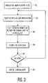
- FIG. 3shows the steps to be executed for the purpose of associating each of plural slave devices with a specific function or key sequence on a wireless master remote control device.
- FIG. 1shows a conceptual diagram of an exemplary embodiment of the present invention.
- the arrangement in FIG. 1is intended to represent use of the techniques of the present invention in a master control computer, such as a remote control device that would be utilized in a wireless embodiment.
- the computerincludes an application software layer 110 which communicates utilizing the modified version of the DALI protocol 114 .
- the lower communications layersare shown as 132 , 134 , 136 , but the particular techniques utilized therein are not critical to the present invention.
- FIG. 1Adepicts a representation of a conventional DALI type of lighting standard as used in a practical system. As shown therein, a series of switches 191 - 192 interface with a master controller 190 to plural ballasts with DALI interface on board 180 - 187 .
- FIG. 1Bdepicts a wireless system 198 , with a central controller 199 (e.g. a remote control) and plural slave devices 160 - 174 as indicated therein. Each button shown on the central controller controls different group of slave devices.
- a central controller 199e.g. a remote control
- the physical layer 136 of FIG. 1 and data link layer 134can be built using an open standard such as Bluetooth, RF lite or any other network standards available in the future for low power low cost wireless data networks. Such standards provide for the reliable transfer of information across the physical link; with the necessary synchronization, error control, and flow control. Then a standardized command set such as a DALI command set layer 118 can be stacked above the physical layer 136 , and data link layer 134 and network layer 132 as shown.
- the systemalso includes an optional applications programming interface (API) 120 as shown.
- APIapplications programming interface
- the DALI command set 118translates commands entered at the application level to DALI commands.
- the next higher layer, DALI command set layermay assume error-free transmission over the link. Therefore, the lower three layers can be transparent to the DALI command set and higher layers. This gives enormous flexibility in adopting different open standards to meet different requirements for different applications without changing the command set and user interface 112 . For example, if the wireless lighting control network is targeted to a home environment, it requires short range and low power radio. If it is for an office or commercial building, it may require a longer communication range and more addressable nodes. Based on these application requirements, different open standards can be selected and implemented as the lower two layers in this model.
- an initialization procedure 116must take place and a short address is assigned to the slave.
- Each slavesuch as a lighting device (e.g., ballast) must register with the master in order to communicate with the master, and to exchange control signals.
- a lighting devicee.g., ballast
- FIG. 2shows the technique, in accordance with an exemplary embodiment of the invention, for associating each of the slave devices with a particular master device/remote control.
- a special enumeration modeis entered in block 201 and a request for enumeration is made, at block 202 , to the master.
- An algorithmis utilized in block 203 to identify the slave. This algorithm may consist of any technique such as, sequential holding by the master of all the slaves, transmitting a signal to the slave and awaiting a response, etc.
- the masterassigns a short address at block 204 in accordance with the DALI protocol, or other such technique.
- the mastere.g. a remote control
- the slavemay blink of f and on in certain sequence for a certain number of times. Whatever signal is agreed upon, the user then responds with a particular confirmation signal, such as depression of a specific key on a keypad.
- the foregoing confirmation stepindicates that the user confirms that the particular device signaling visually is to be associated with the particular master device.
- Decision point 206then returns the program to block 202 to process a new slave device. When all the slave devices have been processed so that they were associated with the proper master, the system returns to normal operation mode at 207 .
- the masterhas to identify the slave by a predetermined algorithm. If the open network standard has its own enumeration procedure or algorithm defined, then the only work the master needs to do is to get the new device information through an API (application programming interface) 120 and utilize this information to proceed with the next steps in the initialization.
- APIapplication programming interface
- the masterneeds to go through a searching algorithm to discover each slave.
- a searching algorithmcan be the modified version of the initialization algorithm specified in DALI standard. It is a binary searching scheme to locate the smallest random address in each round of the search.
- the modification to be madeis to implement CSMA (Carrier Sense Multiple Access) technique to avoid the collision that might happen when two or more slaves try to respond to the master's query.
- CSMACarrier Sense Multiple Access
- the collision problemis particular to a wireless system. It does not create problems during the searching procedure for the wired connections, since even if two or more slaves respond at the same time the master would be able to recognize the overlapped signals on the input line therefore determine that at least one slave is responding.
- the masteridentifies the slave and the master updates its stored data in a manner such that it communicates with the new slave device at the assigned short address
- an indicationis awaited from the user which confirms the assignment of the address.
- the slave devicegives visual feedback, for example, the lamp can flash or blink off, to let the user confirm if this is the right slave that is supposed to be in control of this particular master. Due to the penetration characteristics of RF signals, this step is preferred because any slave in the RF sphere of influence could be included in the control of the master even though it is not supposed to. For example, a lamp in a room on a different floor can be mistakenly initialized to join the network of the master of the room upstairs. The user must, for example, press a button to confirm that the slave device indicating is the right one to include.
- the concept of binding specific functions on a remote control to specific lighting devicesis also addressed in a wireless environment by the present invention.
- the flowchart of FIG. 3is entered at 301 in which the special teaching mode, or binding mode, is entered.
- an active slaveis selected either automatically, or by the depression of a key on the remote control, based on the slave list that the master obtained during the initialization procedure.
- the slavefeeds back with a visual indication so that the user knows which device is active at the current moment.
- an associationis formed at 303 between master and the particular selected slave, for example, by the depression of a key on the remote control by the user.
- the slaveis then released at block 304 , and decision point 305 checks to determine if any other slaves must be bound with specific function keys. If so, a new active slave is selected, and the process repeats itself until each slave is “bound” with a particular function key or sequence of keys.
- This binding processpermits the flexibility of one button (or one command) to be associated to different slave devices dynamically after initialization. More specifically, in hardwired systems, the master may direct commands and information to a particular lighting device by simply transmitting the command or data over the physical wire connected to the particular lighting device. However, in a wireless system, the RF command would be received by all lighting devices since the wired protocols, such as DALI, were not designed in the first place to support wireless communications.
- each of the slave lighting devicesis associated with a particular function or key sequence on the master (e.g. a remote control).
- the mastere.g. a remote control
- the particular function or key sequencedirects the exchange of information to a specific lighting device.
- Another issue that arises as a result of the use of wireless communications in a master slave lighting system such as DALIis the identification of which slave devices are intended to be controlled by a particular master device, such as a remote control. This situation arises, for example, in an office environment wherein there could be one master controlling plural slave devices on the first floor, and a different master controlling slave devices an a second floor.
- the masterIn a hard wired system, the master will know which slaves are under its control simply by the particular hard wired connections between the various slave devices and the master.
- each of the slavesmust be associated with a particular master, and in the second step, specific keys, buttons or functions on the master must be associated with each particular slave.
- these stepsare accomplished by having the master pull the slaves in order to ascertain which slaves should be associated with the particular master, and then specific functions are activated so that particular slaves may be associated with those particular functions or keys.
Landscapes
- Engineering & Computer Science (AREA)
- Computer Networks & Wireless Communication (AREA)
- Physics & Mathematics (AREA)
- General Physics & Mathematics (AREA)
- Selective Calling Equipment (AREA)
Abstract
Description
Claims (20)
Priority Applications (1)
| Application Number | Priority Date | Filing Date | Title |
|---|---|---|---|
| US09/841,665US7417556B2 (en) | 2001-04-24 | 2001-04-24 | Wireless addressable lighting method and apparatus |
Applications Claiming Priority (1)
| Application Number | Priority Date | Filing Date | Title |
|---|---|---|---|
| US09/841,665US7417556B2 (en) | 2001-04-24 | 2001-04-24 | Wireless addressable lighting method and apparatus |
Publications (2)
| Publication Number | Publication Date |
|---|---|
| US20020154025A1 US20020154025A1 (en) | 2002-10-24 |
| US7417556B2true US7417556B2 (en) | 2008-08-26 |
Family
ID=25285422
Family Applications (1)
| Application Number | Title | Priority Date | Filing Date |
|---|---|---|---|
| US09/841,665Expired - LifetimeUS7417556B2 (en) | 2001-04-24 | 2001-04-24 | Wireless addressable lighting method and apparatus |
Country Status (1)
| Country | Link |
|---|---|
| US (1) | US7417556B2 (en) |
Cited By (22)
| Publication number | Priority date | Publication date | Assignee | Title |
|---|---|---|---|---|
| US20070018783A1 (en)* | 2003-09-04 | 2007-01-25 | Koninklijke Philips Electronics N.V. | Digital addressable lighting interface translation method |
| US20070103007A1 (en)* | 2003-12-22 | 2007-05-10 | The Doshisha | Lighting control system |
| US20070229250A1 (en)* | 2006-03-28 | 2007-10-04 | Wireless Lighting Technologies, Llc | Wireless lighting |
| US20070250181A1 (en)* | 2004-10-15 | 2007-10-25 | Koninklijke Philips Electronics, N.V. | Method for Bonding a Lighting Device to a Lighting System While Using Wireless Communication |
| US20090243509A1 (en)* | 2008-03-05 | 2009-10-01 | Thomas Alan Barnett | User interface for wireless lighting control |
| US20090309512A1 (en)* | 2006-07-20 | 2009-12-17 | Gotthard Schleicher | Switchegear, system for controlling a lamp, and light control system for a building comprising at least one light |
| US20100114340A1 (en)* | 2008-06-02 | 2010-05-06 | Charles Huizenga | Automatic provisioning of wireless control systems |
| US20100238047A1 (en)* | 2009-03-20 | 2010-09-23 | Lutron Electronics Co., Inc. | Method of Confirming that a Control Device Complies with a Predefined Protocol Standard |
| US20100241255A1 (en)* | 2009-03-20 | 2010-09-23 | Lutron Electronics Co., Inc. | Method of Semi-Automatic Ballast Replacement |
| WO2010150131A1 (en)* | 2009-06-23 | 2010-12-29 | Koninklijke Philips Electronics N.V. | Pushbits for semi-synchronized pointing |
| US20110109424A1 (en)* | 2009-11-06 | 2011-05-12 | Charles Huizenga | Wireless sensor |
| US20110178650A1 (en)* | 2010-04-01 | 2011-07-21 | Picco Michael L | Computerized Light Control System with Light Level Profiling and Method |
| US20120098692A1 (en)* | 2009-06-23 | 2012-04-26 | Koninklijke Philips Electronics N.V. | Detection using transmission notification |
| US8344641B1 (en) | 2009-09-01 | 2013-01-01 | NuLEDs, Inc. | LED illumination control using simple digital command structure |
| US8364325B2 (en) | 2008-06-02 | 2013-01-29 | Adura Technologies, Inc. | Intelligence in distributed lighting control devices |
| US20130249442A1 (en)* | 2012-03-23 | 2013-09-26 | Martin John Piper | Digital Lighting Sub-Network Interface |
| US8710759B1 (en)* | 2009-09-01 | 2014-04-29 | NuLEDs, Inc. | LED illumination control using a simple digital command structure |
| US9192019B2 (en) | 2011-12-07 | 2015-11-17 | Abl Ip Holding Llc | System for and method of commissioning lighting devices |
| US20150332586A1 (en)* | 2014-05-15 | 2015-11-19 | Savant Systems, Llc | Standalone wireless lighting application |
| US9320112B2 (en) | 2012-04-02 | 2016-04-19 | Kent Tabor | Control system for lighting assembly |
| US9345114B2 (en) | 2013-11-14 | 2016-05-17 | Samsung Electronics Co., Ltd. | Lighting system and signal converting device therefor |
| US11109470B2 (en) | 2017-07-25 | 2021-08-31 | Signify Holding B.V. | Tubular lighting device, luminaire and method for operating with an electronic ballast |
Families Citing this family (41)
| Publication number | Priority date | Publication date | Assignee | Title |
|---|---|---|---|---|
| JP2002353978A (en)* | 2001-05-25 | 2002-12-06 | Pioneer Electronic Corp | Wireless communication terminal having main station or subordinate station function |
| US20040123640A1 (en)* | 2002-07-26 | 2004-07-01 | Rooney Thomas H. | Stripper-plate alignment system and die set |
| US20040217718A1 (en)* | 2003-05-02 | 2004-11-04 | Russikesh Kumar | Digital addressable electronic ballast and control unit |
| DE10323689A1 (en) | 2003-05-22 | 2004-12-09 | Patent-Treuhand-Gesellschaft für elektrische Glühlampen mbH | Controllable lighting system with a second communication protocol and devices therefor |
| US7619539B2 (en)* | 2004-02-13 | 2009-11-17 | Lutron Electronics Co., Inc. | Multiple-input electronic ballast with processor |
| WO2006033062A1 (en)* | 2004-09-22 | 2006-03-30 | Koninklijke Philips Electronics N.V. | Wired and wireless mode lighting device |
| US7369060B2 (en)* | 2004-12-14 | 2008-05-06 | Lutron Electronics Co., Inc. | Distributed intelligence ballast system and extended lighting control protocol |
| US7400594B2 (en)* | 2005-05-03 | 2008-07-15 | Eaton Corporation | Method and system for automated distributed pairing of wireless nodes of a communication network |
| CA2559182C (en) | 2005-09-12 | 2017-05-09 | Acuity Brands, Inc. | Network operation center for a light management system having networked intelligent luminaire managers |
| US7817063B2 (en) | 2005-10-05 | 2010-10-19 | Abl Ip Holding Llc | Method and system for remotely monitoring and controlling field devices with a street lamp elevated mesh network |
| US7555556B2 (en) | 2006-02-09 | 2009-06-30 | Ricoh Company, Ltd. | System, computer program product and method for using a wireless device to control a wireless network device |
| CN101401355B (en) | 2006-03-06 | 2014-10-29 | 皇家飞利浦电子股份有限公司 | Using position for node grouping |
| US7768422B2 (en)* | 2006-09-06 | 2010-08-03 | Carmen Jr Lawrence R | Method of restoring a remote wireless control device to a known state |
| US20080055073A1 (en)* | 2006-09-06 | 2008-03-06 | Lutron Electronics Co., Inc. | Method of discovering a remotely-located wireless control device |
| US7880639B2 (en)* | 2006-09-06 | 2011-02-01 | Lutron Electronics Co., Inc. | Method of establishing communication with wireless control devices |
| US7755505B2 (en)* | 2006-09-06 | 2010-07-13 | Lutron Electronics Co., Inc. | Procedure for addressing remotely-located radio frequency components of a control system |
| US8306051B2 (en)* | 2007-02-08 | 2012-11-06 | Lutron Electronics Co., Inc. | Communication protocol for a lighting control system |
| EP2132961B1 (en)* | 2007-03-27 | 2021-05-12 | Signify Holding B.V. | Control circuit, system for operating a device and device for programming such a control circuit |
| US8140276B2 (en) | 2008-02-27 | 2012-03-20 | Abl Ip Holding Llc | System and method for streetlight monitoring diagnostics |
| WO2013003804A2 (en) | 2011-06-30 | 2013-01-03 | Lutron Electronics Co., Inc. | Method for programming a load control device using a smart phone |
| US10271407B2 (en) | 2011-06-30 | 2019-04-23 | Lutron Electronics Co., Inc. | Load control device having Internet connectivity |
| US9386666B2 (en) | 2011-06-30 | 2016-07-05 | Lutron Electronics Co., Inc. | Method of optically transmitting digital information from a smart phone to a control device |
| WO2013033257A1 (en) | 2011-08-29 | 2013-03-07 | Lutron Electronics Co., Inc. | Two-part load control system mountable to a single electrical wallbox |
| US20130264971A1 (en)* | 2012-03-13 | 2013-10-10 | Verified Energy, Llc | Method of supporting DALI protocol between DALI controllers and devices over an intermediate communication protocol |
| DE102012205964B4 (en)* | 2012-04-12 | 2022-08-18 | Zumtobel Lighting Gmbh | Lighting system and control unit and method therefor |
| WO2014013402A2 (en)* | 2012-07-20 | 2014-01-23 | Koninklijke Philips N.V. | Networked lighting apparatus and method for such lighting apparatus to identify itself and communicate its network address |
| US12300449B2 (en) | 2012-10-26 | 2025-05-13 | Lutron Technology Company Llc | Battery-powered retrofit remote control device |
| US9565742B2 (en) | 2012-10-26 | 2017-02-07 | Lutron Electronics Co., Inc. | Battery-powered retrofit remote control device |
| US10244086B2 (en) | 2012-12-21 | 2019-03-26 | Lutron Electronics Co., Inc. | Multiple network access load control devices |
| US10019047B2 (en) | 2012-12-21 | 2018-07-10 | Lutron Electronics Co., Inc. | Operational coordination of load control devices for control of electrical loads |
| US9413171B2 (en) | 2012-12-21 | 2016-08-09 | Lutron Electronics Co., Inc. | Network access coordination of load control devices |
| US9585226B2 (en) | 2013-03-12 | 2017-02-28 | Lutron Electronics Co., Inc. | Identification of load control devices |
| US10027127B2 (en) | 2013-03-14 | 2018-07-17 | Lutron Electronics Co., Inc. | Commissioning load control systems |
| US10135629B2 (en) | 2013-03-15 | 2018-11-20 | Lutron Electronics Co., Inc. | Load control device user interface and database management using near field communication (NFC) |
| US10339795B2 (en) | 2013-12-24 | 2019-07-02 | Lutron Technology Company Llc | Wireless communication diagnostics |
| RU2653503C2 (en)* | 2014-01-10 | 2018-05-10 | Филипс Лайтинг Холдинг Б.В. | Tablet-based commissioning tool for addressable lighting |
| KR20150140088A (en) | 2014-06-05 | 2015-12-15 | 삼성전자주식회사 | An electronic apparatus and a method for setup of a lighting device |
| US10448486B2 (en) | 2014-06-16 | 2019-10-15 | Samsung Electronics Co., Ltd. | Apparatus and method for controlling lighting device in electronic device |
| US9633557B2 (en) | 2014-06-24 | 2017-04-25 | Lutron Electronics Co., Inc. | Battery-powered retrofit remote control device |
| EP3664380B1 (en)* | 2018-12-06 | 2024-04-24 | Siteco GmbH | Upgradable stage concept for lighting systems |
| DE102019103889A1 (en)* | 2018-12-06 | 2020-06-10 | Siteco Gmbh | Coupling and uncoupling of data and data transport via electrical supply lines for lighting systems |
Citations (10)
| Publication number | Priority date | Publication date | Assignee | Title |
|---|---|---|---|---|
| US5295154A (en)* | 1991-10-01 | 1994-03-15 | Norand Corporation | Radio frequency local area network |
| US5847955A (en)* | 1994-05-04 | 1998-12-08 | National Instruments Corporation | System and method for controlling an instrumentation system |
| US5936362A (en)* | 1993-04-07 | 1999-08-10 | Profile Systems, Llc | Programmable remote control systems for electrical apparatuses |
| US5962992A (en)* | 1997-10-14 | 1999-10-05 | Chaw Khong Co., Ltd. | Lighting control system |
| US6163275A (en)* | 1995-02-15 | 2000-12-19 | Charles James Hartzell | Remotely controlled dimmer |
| US6188181B1 (en)* | 1998-08-25 | 2001-02-13 | Lutron Electronics Co., Inc. | Lighting control system for different load types |
| US6333605B1 (en)* | 1999-11-02 | 2001-12-25 | Energy Savings, Inc. | Light modulating electronic ballast |
| US6507306B1 (en)* | 1999-10-18 | 2003-01-14 | Contec Corporation | Universal remote control unit |
| US6509841B1 (en)* | 1997-10-16 | 2003-01-21 | Cic Global, Llc | System and method for communication between remote locations |
| US6675196B1 (en)* | 1999-01-08 | 2004-01-06 | Amazon.Com, Inc. | Universal protocol for enabling a device to discover and utilize the services of another device |
- 2001
- 2001-04-24USUS09/841,665patent/US7417556B2/ennot_activeExpired - Lifetime
Patent Citations (10)
| Publication number | Priority date | Publication date | Assignee | Title |
|---|---|---|---|---|
| US5295154A (en)* | 1991-10-01 | 1994-03-15 | Norand Corporation | Radio frequency local area network |
| US5936362A (en)* | 1993-04-07 | 1999-08-10 | Profile Systems, Llc | Programmable remote control systems for electrical apparatuses |
| US5847955A (en)* | 1994-05-04 | 1998-12-08 | National Instruments Corporation | System and method for controlling an instrumentation system |
| US6163275A (en)* | 1995-02-15 | 2000-12-19 | Charles James Hartzell | Remotely controlled dimmer |
| US5962992A (en)* | 1997-10-14 | 1999-10-05 | Chaw Khong Co., Ltd. | Lighting control system |
| US6509841B1 (en)* | 1997-10-16 | 2003-01-21 | Cic Global, Llc | System and method for communication between remote locations |
| US6188181B1 (en)* | 1998-08-25 | 2001-02-13 | Lutron Electronics Co., Inc. | Lighting control system for different load types |
| US6675196B1 (en)* | 1999-01-08 | 2004-01-06 | Amazon.Com, Inc. | Universal protocol for enabling a device to discover and utilize the services of another device |
| US6507306B1 (en)* | 1999-10-18 | 2003-01-14 | Contec Corporation | Universal remote control unit |
| US6333605B1 (en)* | 1999-11-02 | 2001-12-25 | Energy Savings, Inc. | Light modulating electronic ballast |
Cited By (43)
| Publication number | Priority date | Publication date | Assignee | Title |
|---|---|---|---|---|
| US20070018783A1 (en)* | 2003-09-04 | 2007-01-25 | Koninklijke Philips Electronics N.V. | Digital addressable lighting interface translation method |
| US7633406B2 (en)* | 2003-12-22 | 2009-12-15 | The Doshisha | Lighting control system |
| US20070103007A1 (en)* | 2003-12-22 | 2007-05-10 | The Doshisha | Lighting control system |
| US20070250181A1 (en)* | 2004-10-15 | 2007-10-25 | Koninklijke Philips Electronics, N.V. | Method for Bonding a Lighting Device to a Lighting System While Using Wireless Communication |
| US7590457B2 (en)* | 2004-10-15 | 2009-09-15 | Koninklijke Philips Electronics N.V. | Method for bonding a lighting device to a lighting system while using wireless communication |
| US20070229250A1 (en)* | 2006-03-28 | 2007-10-04 | Wireless Lighting Technologies, Llc | Wireless lighting |
| US8129921B2 (en)* | 2006-07-20 | 2012-03-06 | Osram Ag | Switchegear, system for controlling a lamp, and light control system for a building comprising at least one light |
| US20090309512A1 (en)* | 2006-07-20 | 2009-12-17 | Gotthard Schleicher | Switchegear, system for controlling a lamp, and light control system for a building comprising at least one light |
| US20090243509A1 (en)* | 2008-03-05 | 2009-10-01 | Thomas Alan Barnett | User interface for wireless lighting control |
| US20100114340A1 (en)* | 2008-06-02 | 2010-05-06 | Charles Huizenga | Automatic provisioning of wireless control systems |
| US10139787B2 (en) | 2008-06-02 | 2018-11-27 | Abl Ip Holding Llc | Intelligence in distributed lighting control devices |
| US9664814B2 (en) | 2008-06-02 | 2017-05-30 | Abl Ip Holding Llc | Wireless sensor |
| US8364325B2 (en) | 2008-06-02 | 2013-01-29 | Adura Technologies, Inc. | Intelligence in distributed lighting control devices |
| US20100241255A1 (en)* | 2009-03-20 | 2010-09-23 | Lutron Electronics Co., Inc. | Method of Semi-Automatic Ballast Replacement |
| US8536984B2 (en) | 2009-03-20 | 2013-09-17 | Lutron Electronics Co., Inc. | Method of semi-automatic ballast replacement |
| US20100238047A1 (en)* | 2009-03-20 | 2010-09-23 | Lutron Electronics Co., Inc. | Method of Confirming that a Control Device Complies with a Predefined Protocol Standard |
| US8680969B2 (en)* | 2009-03-20 | 2014-03-25 | Lutron Electronics Co., Inc. | Method of confirming that a control device complies with a predefined protocol standard |
| US8994517B2 (en)* | 2009-06-23 | 2015-03-31 | Koninklijkle Philips N.V. | Detection using transmission notification |
| US8981912B2 (en) | 2009-06-23 | 2015-03-17 | Koninklijkle Philips N.V. | Pushbits for semi-synchronized pointing |
| US20120098692A1 (en)* | 2009-06-23 | 2012-04-26 | Koninklijke Philips Electronics N.V. | Detection using transmission notification |
| WO2010150131A1 (en)* | 2009-06-23 | 2010-12-29 | Koninklijke Philips Electronics N.V. | Pushbits for semi-synchronized pointing |
| US9601008B2 (en) | 2009-06-23 | 2017-03-21 | Philips Lighting Holding B.V. | Detection using transmission notification |
| CN102483879B (en)* | 2009-06-23 | 2015-09-30 | 皇家飞利浦电子股份有限公司 | Remote controllers and utilize it to select the method for light source from multiple light source |
| CN102483879A (en)* | 2009-06-23 | 2012-05-30 | 皇家飞利浦电子股份有限公司 | Improved detection using send notifications |
| US8710759B1 (en)* | 2009-09-01 | 2014-04-29 | NuLEDs, Inc. | LED illumination control using a simple digital command structure |
| US8344641B1 (en) | 2009-09-01 | 2013-01-01 | NuLEDs, Inc. | LED illumination control using simple digital command structure |
| US8275471B2 (en) | 2009-11-06 | 2012-09-25 | Adura Technologies, Inc. | Sensor interface for wireless control |
| US8854208B2 (en) | 2009-11-06 | 2014-10-07 | Abl Ip Holding Llc | Wireless sensor |
| US8755915B2 (en) | 2009-11-06 | 2014-06-17 | Abl Ip Holding Llc | Sensor interface for wireless control |
| US20110109424A1 (en)* | 2009-11-06 | 2011-05-12 | Charles Huizenga | Wireless sensor |
| US8280558B2 (en) | 2010-04-01 | 2012-10-02 | ESI Ventures, LLC | Computerized light control system with light level profiling and method |
| US20110178650A1 (en)* | 2010-04-01 | 2011-07-21 | Picco Michael L | Computerized Light Control System with Light Level Profiling and Method |
| US9192019B2 (en) | 2011-12-07 | 2015-11-17 | Abl Ip Holding Llc | System for and method of commissioning lighting devices |
| US10111308B2 (en) | 2011-12-07 | 2018-10-23 | Abl Ip Holding Llc | System for and method of commissioning lighting devices within a wireless network |
| US9888548B2 (en) | 2011-12-07 | 2018-02-06 | Abl Ip Holding Llc | System for and method of commissioning lighting devices |
| US20130249442A1 (en)* | 2012-03-23 | 2013-09-26 | Martin John Piper | Digital Lighting Sub-Network Interface |
| US9241389B2 (en)* | 2012-03-23 | 2016-01-19 | Cooper Technologies Company | Digital lighting sub-network interface |
| US9320112B2 (en) | 2012-04-02 | 2016-04-19 | Kent Tabor | Control system for lighting assembly |
| US9578714B2 (en) | 2013-11-14 | 2017-02-21 | Samsung Electronics Co., Ltd. | Lighting system and signal converting device therefor |
| US9345114B2 (en) | 2013-11-14 | 2016-05-17 | Samsung Electronics Co., Ltd. | Lighting system and signal converting device therefor |
| US10032364B2 (en)* | 2014-05-15 | 2018-07-24 | Savant Systems, Llc | Standalone wireless lighting application |
| US20150332586A1 (en)* | 2014-05-15 | 2015-11-19 | Savant Systems, Llc | Standalone wireless lighting application |
| US11109470B2 (en) | 2017-07-25 | 2021-08-31 | Signify Holding B.V. | Tubular lighting device, luminaire and method for operating with an electronic ballast |
Also Published As
| Publication number | Publication date |
|---|---|
| US20020154025A1 (en) | 2002-10-24 |
Similar Documents
| Publication | Publication Date | Title |
|---|---|---|
| US7417556B2 (en) | Wireless addressable lighting method and apparatus | |
| US6901439B1 (en) | Method of adding a device to a network | |
| US7126291B2 (en) | Radio frequency lighting control system programming device and method | |
| US6865428B2 (en) | Method and apparatus for providing distributed control of a home automation system | |
| US10743390B2 (en) | Out-of-the-box commissioning of a control system | |
| US5471190A (en) | Method and apparatus for resource allocation in a communication network system | |
| US6990379B2 (en) | Method and apparatus for providing a dynamic resource role model for subscriber-requester based protocols in a home automation and control system | |
| EP1569419B1 (en) | Method of assigning addresses to a plurality of devices on a network and a network system therefor | |
| JP2003009261A (en) | System and method for routing table construction and signal routing in automation systems | |
| CN107566229A (en) | The packet control process of intelligent domestic system | |
| US6529119B1 (en) | Establishment of communications with a selected device in a multi-device environment | |
| US20040111496A1 (en) | Home network system and method for adding and/or deleting home appliances | |
| CN113009838A (en) | Smart home control method, terminal device and smart home control system | |
| WO2000043900A1 (en) | Method of adding a device to a network | |
| JP2006244416A (en) | Electronic device system having a master node and a slave node | |
| CN106354060B (en) | Master-slave communication method of guest room control device | |
| EP3689111A1 (en) | A method of commissioning a wired communication network | |
| US8922349B2 (en) | Control circuit, system for operating a device and device for programming such a control circuit | |
| KR100386599B1 (en) | method for separation multiple home network | |
| EP3175586B1 (en) | Residential automation system, equipment and process that is easy to install, configure and use | |
| WO2001028156A2 (en) | Low power radio network | |
| WO2002071644A1 (en) | Plug-and-play power line communication device | |
| JP4103499B2 (en) | Communication device | |
| EP1523828B1 (en) | Method for separating multiple home networks | |
| CN106292614B (en) | Guest room networking control system |
Legal Events
| Date | Code | Title | Description |
|---|---|---|---|
| AS | Assignment | Owner name:KONINKLIJKE PHILIPS ELECTRONICS, N.V., NETHERLANDS Free format text:ASSIGNMENT OF ASSIGNORS INTEREST;ASSIGNOR:WANG, LING;REEL/FRAME:011804/0840 Effective date:20010423 | |
| STCF | Information on status: patent grant | Free format text:PATENTED CASE | |
| FPAY | Fee payment | Year of fee payment:4 | |
| FPAY | Fee payment | Year of fee payment:8 | |
| AS | Assignment | Owner name:KONINKLIJKE PHILIPS N.V., NETHERLANDS Free format text:CHANGE OF NAME;ASSIGNOR:KONINKLIJKE PHILIPS ELECTRONICS N.V.;REEL/FRAME:039428/0606 Effective date:20130515 | |
| AS | Assignment | Owner name:PHILIPS LIGHTING HOLDING B.V., NETHERLANDS Free format text:ASSIGNMENT OF ASSIGNORS INTEREST;ASSIGNOR:KONINKLIJKE PHILIPS N.V.;REEL/FRAME:040060/0009 Effective date:20160607 | |
| AS | Assignment | Owner name:SIGNIFY HOLDING B.V., NETHERLANDS Free format text:CHANGE OF NAME;ASSIGNOR:PHILIPS LIGHTING HOLDING B.V.;REEL/FRAME:050837/0576 Effective date:20190201 | |
| MAFP | Maintenance fee payment | Free format text:PAYMENT OF MAINTENANCE FEE, 12TH YEAR, LARGE ENTITY (ORIGINAL EVENT CODE: M1553); ENTITY STATUS OF PATENT OWNER: LARGE ENTITY Year of fee payment:12 |