US7416541B2 - Intracutaneous microneedle array apparatus - Google Patents
Intracutaneous microneedle array apparatusDownload PDFInfo
- Publication number
- US7416541B2 US7416541B2US11/121,291US12129105AUS7416541B2US 7416541 B2US7416541 B2US 7416541B2US 12129105 AUS12129105 AUS 12129105AUS 7416541 B2US7416541 B2US 7416541B2
- Authority
- US
- United States
- Prior art keywords
- microns
- microneedles
- range
- microneedle
- recited
- Prior art date
- Legal status (The legal status is an assumption and is not a legal conclusion. Google has not performed a legal analysis and makes no representation as to the accuracy of the status listed.)
- Expired - Lifetime
Links
- 210000003491skinAnatomy0.000claimsabstractdescription104
- 238000000926separation methodMethods0.000claimsabstractdescription72
- 239000007787solidSubstances0.000claimsabstractdescription67
- 210000000434stratum corneumAnatomy0.000claimsabstractdescription55
- 230000035515penetrationEffects0.000claimsabstractdescription34
- 238000000034methodMethods0.000claimsdescription134
- 239000000463materialSubstances0.000claimsdescription113
- 229920003023plasticPolymers0.000claimsdescription79
- 239000004033plasticSubstances0.000claimsdescription79
- 238000004519manufacturing processMethods0.000claimsdescription29
- 230000008569processEffects0.000claimsdescription29
- 239000007788liquidSubstances0.000claimsdescription15
- 238000001053micromouldingMethods0.000claimsdescription13
- 239000004065semiconductorSubstances0.000claimsdescription13
- 230000000149penetrating effectEffects0.000claimsdescription9
- 239000007769metal materialSubstances0.000claimsdescription8
- 238000005459micromachiningMethods0.000claimsdescription8
- 230000001747exhibiting effectEffects0.000claims2
- 239000013060biological fluidSubstances0.000abstractdescription14
- 238000003491arrayMethods0.000abstractdescription13
- 210000003722extracellular fluidAnatomy0.000abstractdescription12
- 239000012530fluidSubstances0.000description74
- 239000000758substrateSubstances0.000description60
- 238000012377drug deliveryMethods0.000description39
- 239000003814drugSubstances0.000description38
- 229940079593drugDrugs0.000description37
- 238000000465mouldingMethods0.000description31
- 230000004907fluxEffects0.000description26
- 229910052751metalInorganic materials0.000description24
- 239000002184metalSubstances0.000description24
- 210000001124body fluidAnatomy0.000description23
- 239000010839body fluidSubstances0.000description23
- 238000005070samplingMethods0.000description22
- 210000004207dermisAnatomy0.000description21
- 210000002615epidermisAnatomy0.000description21
- XUIMIQQOPSSXEZ-UHFFFAOYSA-NSiliconChemical compound[Si]XUIMIQQOPSSXEZ-UHFFFAOYSA-N0.000description20
- 230000008901benefitEffects0.000description20
- 239000010703siliconSubstances0.000description20
- 239000000126substanceSubstances0.000description19
- 229910052710siliconInorganic materials0.000description18
- 229920000642polymerPolymers0.000description16
- WQZGKKKJIJFFOK-GASJEMHNSA-NGlucoseNatural productsOC[C@H]1OC(O)[C@H](O)[C@@H](O)[C@@H]1OWQZGKKKJIJFFOK-GASJEMHNSA-N0.000description15
- 239000008103glucoseSubstances0.000description15
- NOESYZHRGYRDHS-UHFFFAOYSA-NinsulinChemical compoundN1C(=O)C(NC(=O)C(CCC(N)=O)NC(=O)C(CCC(O)=O)NC(=O)C(C(C)C)NC(=O)C(NC(=O)CN)C(C)CC)CSSCC(C(NC(CO)C(=O)NC(CC(C)C)C(=O)NC(CC=2C=CC(O)=CC=2)C(=O)NC(CCC(N)=O)C(=O)NC(CC(C)C)C(=O)NC(CCC(O)=O)C(=O)NC(CC(N)=O)C(=O)NC(CC=2C=CC(O)=CC=2)C(=O)NC(CSSCC(NC(=O)C(C(C)C)NC(=O)C(CC(C)C)NC(=O)C(CC=2C=CC(O)=CC=2)NC(=O)C(CC(C)C)NC(=O)C(C)NC(=O)C(CCC(O)=O)NC(=O)C(C(C)C)NC(=O)C(CC(C)C)NC(=O)C(CC=2NC=NC=2)NC(=O)C(CO)NC(=O)CNC2=O)C(=O)NCC(=O)NC(CCC(O)=O)C(=O)NC(CCCNC(N)=N)C(=O)NCC(=O)NC(CC=3C=CC=CC=3)C(=O)NC(CC=3C=CC=CC=3)C(=O)NC(CC=3C=CC(O)=CC=3)C(=O)NC(C(C)O)C(=O)N3C(CCC3)C(=O)NC(CCCCN)C(=O)NC(C)C(O)=O)C(=O)NC(CC(N)=O)C(O)=O)=O)NC(=O)C(C(C)CC)NC(=O)C(CO)NC(=O)C(C(C)O)NC(=O)C1CSSCC2NC(=O)C(CC(C)C)NC(=O)C(NC(=O)C(CCC(N)=O)NC(=O)C(CC(N)=O)NC(=O)C(NC(=O)C(N)CC=1C=CC=CC=1)C(C)C)CC1=CN=CN1NOESYZHRGYRDHS-UHFFFAOYSA-N0.000description14
- 239000002985plastic filmSubstances0.000description13
- 229920006255plastic filmPolymers0.000description13
- 108090000790EnzymesProteins0.000description12
- 102000004190EnzymesHuman genes0.000description12
- 229910052581Si3N4Inorganic materials0.000description12
- VYPSYNLAJGMNEJ-UHFFFAOYSA-NSilicium dioxideChemical classO=[Si]=OVYPSYNLAJGMNEJ-UHFFFAOYSA-N0.000description12
- -1analgeticsSubstances0.000description12
- 229940088598enzymeDrugs0.000description12
- 239000000017hydrogelSubstances0.000description12
- HQVNEWCFYHHQES-UHFFFAOYSA-Nsilicon nitrideChemical compoundN12[Si]34N5[Si]62N3[Si]51N64HQVNEWCFYHHQES-UHFFFAOYSA-N0.000description12
- 238000001962electrophoresisMethods0.000description11
- 230000036961partial effectEffects0.000description11
- 229920003229poly(methyl methacrylate)Polymers0.000description11
- 229920002120photoresistant polymerPolymers0.000description10
- 210000001519tissueAnatomy0.000description10
- 239000008280bloodSubstances0.000description9
- 210000004369bloodAnatomy0.000description9
- 238000013461designMethods0.000description9
- 230000037368penetrate the skinEffects0.000description9
- 239000004926polymethyl methacrylateSubstances0.000description9
- 229920000249biocompatible polymerPolymers0.000description8
- 230000000694effectsEffects0.000description8
- 230000003287optical effectEffects0.000description8
- 238000012545processingMethods0.000description8
- 239000000243solutionSubstances0.000description8
- 102000004877InsulinHuman genes0.000description7
- 108090001061InsulinProteins0.000description7
- 230000005684electric fieldEffects0.000description7
- 229940125396insulinDrugs0.000description7
- 239000002861polymer materialSubstances0.000description7
- 230000037380skin damageEffects0.000description7
- PXHVJJICTQNCMI-UHFFFAOYSA-NNickelChemical compound[Ni]PXHVJJICTQNCMI-UHFFFAOYSA-N0.000description6
- 239000003795chemical substances by applicationSubstances0.000description6
- 238000000576coating methodMethods0.000description6
- 238000004891communicationMethods0.000description6
- 230000002500effect on skinEffects0.000description6
- 238000005530etchingMethods0.000description6
- 230000006872improvementEffects0.000description6
- 238000002844meltingMethods0.000description6
- 230000008018meltingEffects0.000description6
- HBMJWWWQQXIZIP-UHFFFAOYSA-Nsilicon carbideChemical compound[Si+]#[C-]HBMJWWWQQXIZIP-UHFFFAOYSA-N0.000description6
- 229910010271silicon carbideInorganic materials0.000description6
- 238000002604ultrasonographyMethods0.000description6
- XLYOFNOQVPJJNP-UHFFFAOYSA-NwaterSubstancesOXLYOFNOQVPJJNP-UHFFFAOYSA-N0.000description6
- 241001465754MetazoaSpecies0.000description5
- DFPAKSUCGFBDDF-UHFFFAOYSA-NNicotinamideChemical compoundNC(=O)C1=CC=CN=C1DFPAKSUCGFBDDF-UHFFFAOYSA-N0.000description5
- 239000011248coating agentSubstances0.000description5
- 238000010276constructionMethods0.000description5
- 238000009792diffusion processMethods0.000description5
- 238000004049embossingMethods0.000description5
- 238000002347injectionMethods0.000description5
- 239000007924injectionSubstances0.000description5
- 238000003754machiningMethods0.000description5
- 230000007246mechanismEffects0.000description5
- 150000002739metalsChemical class0.000description5
- 238000000520microinjectionMethods0.000description5
- 229960003966nicotinamideDrugs0.000description5
- 235000005152nicotinamideNutrition0.000description5
- 239000011570nicotinamideSubstances0.000description5
- 230000002829reductive effectEffects0.000description5
- 230000002441reversible effectEffects0.000description5
- 239000000377silicon dioxideSubstances0.000description5
- 229960001866silicon dioxideDrugs0.000description5
- 235000012239silicon dioxideNutrition0.000description5
- XEEYBQQBJWHFJM-UHFFFAOYSA-NIronChemical compound[Fe]XEEYBQQBJWHFJM-UHFFFAOYSA-N0.000description4
- 230000008859changeEffects0.000description4
- 150000001875compoundsChemical class0.000description4
- 230000007423decreaseEffects0.000description4
- 230000002708enhancing effectEffects0.000description4
- 208000014674injuryDiseases0.000description4
- 150000002500ionsChemical class0.000description4
- 239000002648laminated materialSubstances0.000description4
- 238000005259measurementMethods0.000description4
- 238000012986modificationMethods0.000description4
- 230000004048modificationEffects0.000description4
- 238000012544monitoring processMethods0.000description4
- 230000035699permeabilityEffects0.000description4
- 230000008733traumaEffects0.000description4
- 230000000202analgesic effectEffects0.000description3
- 230000004888barrier functionEffects0.000description3
- 210000004027cellAnatomy0.000description3
- 229920001940conductive polymerPolymers0.000description3
- 229910052802copperInorganic materials0.000description3
- 239000010949copperSubstances0.000description3
- 238000005516engineering processMethods0.000description3
- 230000009477glass transitionEffects0.000description3
- 230000001965increasing effectEffects0.000description3
- 239000002991molded plasticSubstances0.000description3
- 210000003205muscleAnatomy0.000description3
- 229910052759nickelInorganic materials0.000description3
- 229920006254polymer filmPolymers0.000description3
- 238000003825pressingMethods0.000description3
- 238000013271transdermal drug deliveryMethods0.000description3
- 238000012546transferMethods0.000description3
- 230000000007visual effectEffects0.000description3
- SNICXCGAKADSCV-JTQLQIEISA-N(-)-NicotineChemical compoundCN1CCC[C@H]1C1=CC=CN=C1SNICXCGAKADSCV-JTQLQIEISA-N0.000description2
- VEXZGXHMUGYJMC-UHFFFAOYSA-MChloride anionChemical compound[Cl-]VEXZGXHMUGYJMC-UHFFFAOYSA-M0.000description2
- RYGMFSIKBFXOCR-UHFFFAOYSA-NCopperChemical compound[Cu]RYGMFSIKBFXOCR-UHFFFAOYSA-N0.000description2
- RTZKZFJDLAIYFH-UHFFFAOYSA-NDiethyl etherChemical compoundCCOCCRTZKZFJDLAIYFH-UHFFFAOYSA-N0.000description2
- 241000196324EmbryophytaSpecies0.000description2
- 108010015776Glucose oxidaseProteins0.000description2
- 239000004366Glucose oxidaseSubstances0.000description2
- DGAQECJNVWCQMB-PUAWFVPOSA-MIlexoside XXIXChemical compoundC[C@@H]1CC[C@@]2(CC[C@@]3(C(=CC[C@H]4[C@]3(CC[C@@H]5[C@@]4(CC[C@@H](C5(C)C)OS(=O)(=O)[O-])C)C)[C@@H]2[C@]1(C)O)C)C(=O)O[C@H]6[C@@H]([C@H]([C@@H]([C@H](O6)CO)O)O)O.[Na+]DGAQECJNVWCQMB-PUAWFVPOSA-M0.000description2
- 229930040373ParaformaldehydeNatural products0.000description2
- 229920006397acrylic thermoplasticPolymers0.000description2
- 239000000853adhesiveSubstances0.000description2
- 230000001070adhesive effectEffects0.000description2
- 229910052782aluminiumInorganic materials0.000description2
- XAGFODPZIPBFFR-UHFFFAOYSA-NaluminiumChemical compound[Al]XAGFODPZIPBFFR-UHFFFAOYSA-N0.000description2
- 238000004458analytical methodMethods0.000description2
- 230000000712assemblyEffects0.000description2
- 238000000429assemblyMethods0.000description2
- 239000000560biocompatible materialSubstances0.000description2
- 238000002512chemotherapyMethods0.000description2
- 239000002131composite materialSubstances0.000description2
- 239000002537cosmeticSubstances0.000description2
- 238000000151depositionMethods0.000description2
- 230000008021depositionEffects0.000description2
- 238000001514detection methodMethods0.000description2
- 229910003460diamondInorganic materials0.000description2
- 239000010432diamondSubstances0.000description2
- 238000009713electroplatingMethods0.000description2
- 229940116332glucose oxidaseDrugs0.000description2
- 235000019420glucose oxidaseNutrition0.000description2
- 229910052737goldInorganic materials0.000description2
- 239000010931goldSubstances0.000description2
- 230000001939inductive effectEffects0.000description2
- 229910052742ironInorganic materials0.000description2
- 239000000203mixtureSubstances0.000description2
- 229910021421monocrystalline siliconInorganic materials0.000description2
- 210000005036nerveAnatomy0.000description2
- 229960002715nicotineDrugs0.000description2
- SNICXCGAKADSCV-UHFFFAOYSA-NnicotineNatural productsCN1CCCC1C1=CC=CN=C1SNICXCGAKADSCV-UHFFFAOYSA-N0.000description2
- 210000000496pancreasAnatomy0.000description2
- 239000002245particleSubstances0.000description2
- 238000001020plasma etchingMethods0.000description2
- 229920001606poly(lactic acid-co-glycolic acid)Polymers0.000description2
- 229920006324polyoxymethylenePolymers0.000description2
- 229920002635polyurethanePolymers0.000description2
- 239000004814polyurethaneSubstances0.000description2
- 229910052814silicon oxideInorganic materials0.000description2
- 239000002210silicon-based materialSubstances0.000description2
- 229910052708sodiumInorganic materials0.000description2
- 239000011734sodiumSubstances0.000description2
- 229910001220stainless steelInorganic materials0.000description2
- 239000010935stainless steelSubstances0.000description2
- 238000003860storageMethods0.000description2
- ISXSCDLOGDJUNJ-UHFFFAOYSA-Ntert-butyl prop-2-enoateChemical compoundCC(C)(C)OC(=O)C=CISXSCDLOGDJUNJ-UHFFFAOYSA-N0.000description2
- 238000002560therapeutic procedureMethods0.000description2
- 230000000699topical effectEffects0.000description2
- 230000037317transdermal deliveryEffects0.000description2
- 239000012780transparent materialSubstances0.000description2
- WFKWXMTUELFFGS-UHFFFAOYSA-NtungstenChemical compound[W]WFKWXMTUELFFGS-UHFFFAOYSA-N0.000description2
- 229910052721tungstenInorganic materials0.000description2
- 239000010937tungstenSubstances0.000description2
- OXHNLMTVIGZXSG-UHFFFAOYSA-N1-MethylpyrroleChemical compoundCN1C=CC=C1OXHNLMTVIGZXSG-UHFFFAOYSA-N0.000description1
- OSSNTDFYBPYIEC-UHFFFAOYSA-N1-ethenylimidazoleChemical compoundC=CN1C=CN=C1OSSNTDFYBPYIEC-UHFFFAOYSA-N0.000description1
- KGIGUEBEKRSTEW-UHFFFAOYSA-N2-vinylpyridineChemical compoundC=CC1=CC=CC=N1KGIGUEBEKRSTEW-UHFFFAOYSA-N0.000description1
- KBZALDXXIMXRBJ-UHFFFAOYSA-N5-methylphenazin-5-iumChemical compoundC1=CC=C2[N+](C)=C(C=CC=C3)C3=NC2=C1KBZALDXXIMXRBJ-UHFFFAOYSA-N0.000description1
- RZVAJINKPMORJF-UHFFFAOYSA-NAcetaminophenChemical compoundCC(=O)NC1=CC=C(O)C=C1RZVAJINKPMORJF-UHFFFAOYSA-N0.000description1
- QTBSBXVTEAMEQO-UHFFFAOYSA-MAcetateChemical compoundCC([O-])=OQTBSBXVTEAMEQO-UHFFFAOYSA-M0.000description1
- NOWKCMXCCJGMRR-UHFFFAOYSA-NAziridineChemical compoundC1CN1NOWKCMXCCJGMRR-UHFFFAOYSA-N0.000description1
- ROFVEXUMMXZLPA-UHFFFAOYSA-NBipyridylChemical compoundN1=CC=CC=C1C1=CC=CC=N1ROFVEXUMMXZLPA-UHFFFAOYSA-N0.000description1
- 241000938605CrocodyliaSpecies0.000description1
- 229920000858CyclodextrinPolymers0.000description1
- 239000004593EpoxySubstances0.000description1
- 208000010228Erectile DysfunctionDiseases0.000description1
- 239000004812Fluorinated ethylene propyleneSubstances0.000description1
- 108010010803GelatinProteins0.000description1
- SXRSQZLOMIGNAQ-UHFFFAOYSA-NGlutaraldehydeChemical compoundO=CCCCC=OSXRSQZLOMIGNAQ-UHFFFAOYSA-N0.000description1
- 241000282412HomoSpecies0.000description1
- 229920000557Nafion®Polymers0.000description1
- 241000183666Nepsera aquaticaSpecies0.000description1
- SNIOPGDIGTZGOP-UHFFFAOYSA-NNitroglycerinChemical compound[O-][N+](=O)OCC(O[N+]([O-])=O)CO[N+]([O-])=OSNIOPGDIGTZGOP-UHFFFAOYSA-N0.000description1
- 239000000006NitroglycerinSubstances0.000description1
- 239000004677NylonSubstances0.000description1
- 239000004952PolyamideSubstances0.000description1
- 239000004642PolyimideSubstances0.000description1
- 229920000265PolyparaphenylenePolymers0.000description1
- 239000004793PolystyreneSubstances0.000description1
- 206010037660PyrexiaDiseases0.000description1
- 206010040880Skin irritationDiseases0.000description1
- 238000010521absorption reactionMethods0.000description1
- 239000004676acrylonitrile butadiene styreneSubstances0.000description1
- 150000008360acrylonitrilesChemical class0.000description1
- 239000011149active materialSubstances0.000description1
- 229910045601alloyInorganic materials0.000description1
- 239000000956alloySubstances0.000description1
- 239000012491analyteSubstances0.000description1
- 229940121363anti-inflammatory agentDrugs0.000description1
- 239000002260anti-inflammatory agentSubstances0.000description1
- 230000000078anti-malarial effectEffects0.000description1
- 230000001754anti-pyretic effectEffects0.000description1
- 230000002921anti-spasmodic effectEffects0.000description1
- 229940125681anticonvulsant agentDrugs0.000description1
- 239000001961anticonvulsive agentSubstances0.000description1
- 239000004599antimicrobialSubstances0.000description1
- 239000003096antiparasitic agentSubstances0.000description1
- 229940125687antiparasitic agentDrugs0.000description1
- 239000000939antiparkinson agentSubstances0.000description1
- 229940125688antiparkinson agentDrugs0.000description1
- 239000002221antipyreticSubstances0.000description1
- 229940125716antipyretic agentDrugs0.000description1
- 229940124575antispasmodic agentDrugs0.000description1
- 239000003699antiulcer agentSubstances0.000description1
- 238000013459approachMethods0.000description1
- 238000000149argon plasma sinteringMethods0.000description1
- QVGXLLKOCUKJST-UHFFFAOYSA-Natomic oxygenChemical compound[O]QVGXLLKOCUKJST-UHFFFAOYSA-N0.000description1
- 239000012620biological materialSubstances0.000description1
- 230000031018biological processes and functionsEffects0.000description1
- 230000000740bleeding effectEffects0.000description1
- 238000004159blood analysisMethods0.000description1
- 230000017531blood circulationEffects0.000description1
- 238000005266castingMethods0.000description1
- 229920002678cellulosePolymers0.000description1
- 239000001913celluloseSubstances0.000description1
- 210000003169central nervous systemAnatomy0.000description1
- 239000000919ceramicChemical class0.000description1
- 238000006243chemical reactionMethods0.000description1
- 239000003153chemical reaction reagentSubstances0.000description1
- 229910052804chromiumInorganic materials0.000description1
- 239000004020conductorSubstances0.000description1
- 238000011109contaminationMethods0.000description1
- 238000001816coolingMethods0.000description1
- 229920001577copolymerPolymers0.000description1
- 239000013078crystalSubstances0.000description1
- 229910021419crystalline siliconInorganic materials0.000description1
- 230000006378damageEffects0.000description1
- 206010012601diabetes mellitusDiseases0.000description1
- 238000004512die castingMethods0.000description1
- 125000000118dimethyl groupChemical group[H]C([H])([H])*0.000description1
- 238000007598dipping methodMethods0.000description1
- 238000005553drillingMethods0.000description1
- 230000005611electricityEffects0.000description1
- 238000000840electrochemical analysisMethods0.000description1
- 239000007772electrode materialSubstances0.000description1
- 238000004070electrodepositionMethods0.000description1
- 238000005370electroosmosisMethods0.000description1
- 238000004520electroporationMethods0.000description1
- 210000003372endocrine glandAnatomy0.000description1
- 239000003623enhancerSubstances0.000description1
- 150000002118epoxidesChemical class0.000description1
- 125000003700epoxy groupChemical group0.000description1
- 230000003628erosive effectEffects0.000description1
- 238000011049fillingMethods0.000description1
- 239000011888foilSubstances0.000description1
- 210000000245forearmAnatomy0.000description1
- 239000000499gelSubstances0.000description1
- 229920000159gelatinPolymers0.000description1
- 239000008273gelatinSubstances0.000description1
- 235000019322gelatineNutrition0.000description1
- 235000011852gelatine dessertsNutrition0.000description1
- 229960003711glyceryl trinitrateDrugs0.000description1
- PCHJSUWPFVWCPO-UHFFFAOYSA-NgoldChemical compound[Au]PCHJSUWPFVWCPO-UHFFFAOYSA-N0.000description1
- 210000003780hair follicleAnatomy0.000description1
- 230000003054hormonal effectEffects0.000description1
- 238000001794hormone therapyMethods0.000description1
- 201000001881impotenceDiseases0.000description1
- 238000001746injection mouldingMethods0.000description1
- 238000003780insertionMethods0.000description1
- 230000037431insertionEffects0.000description1
- 238000005304joiningMethods0.000description1
- 238000000608laser ablationMethods0.000description1
- 238000002386leachingMethods0.000description1
- 239000004973liquid crystal related substanceSubstances0.000description1
- 230000000873masking effectEffects0.000description1
- 239000011159matrix materialSubstances0.000description1
- 239000012528membraneSubstances0.000description1
- 229910001092metal group alloyInorganic materials0.000description1
- 229940035363muscle relaxantsDrugs0.000description1
- 239000003158myorelaxant agentSubstances0.000description1
- 230000001613neoplastic effectEffects0.000description1
- 150000004767nitridesChemical class0.000description1
- 230000037311normal skinEffects0.000description1
- 235000016709nutritionNutrition0.000description1
- 229920001778nylonPolymers0.000description1
- 229940126701oral medicationDrugs0.000description1
- 229910052762osmiumInorganic materials0.000description1
- SYQBFIAQOQZEGI-UHFFFAOYSA-Nosmium atomChemical compound[Os]SYQBFIAQOQZEGI-UHFFFAOYSA-N0.000description1
- 230000003647oxidationEffects0.000description1
- 238000007254oxidation reactionMethods0.000description1
- 229910052760oxygenInorganic materials0.000description1
- 239000001301oxygenSubstances0.000description1
- 230000037361pathwayEffects0.000description1
- 229920009441perflouroethylene propylenePolymers0.000description1
- 230000000737periodic effectEffects0.000description1
- 230000000144pharmacologic effectEffects0.000description1
- 230000037081physical activityEffects0.000description1
- 229910052697platinumInorganic materials0.000description1
- 229920000052poly(p-xylylene)Polymers0.000description1
- 229920000553poly(phenylenevinylene)Polymers0.000description1
- 229920002647polyamidePolymers0.000description1
- 229920000767polyanilinePolymers0.000description1
- 239000004417polycarbonateSubstances0.000description1
- 229920000515polycarbonatePolymers0.000description1
- 229920000647polyepoxidePolymers0.000description1
- 229920000728polyesterPolymers0.000description1
- 229920001223polyethylene glycolPolymers0.000description1
- 229920001721polyimidePolymers0.000description1
- 235000013824polyphenolsNutrition0.000description1
- 229920001296polysiloxanePolymers0.000description1
- 229920002223polystyrenePolymers0.000description1
- 229920000123polythiophenePolymers0.000description1
- 239000011148porous materialSubstances0.000description1
- 239000000843powderSubstances0.000description1
- 238000002360preparation methodMethods0.000description1
- 230000001681protective effectEffects0.000description1
- 230000003236psychic effectEffects0.000description1
- 238000005086pumpingMethods0.000description1
- 239000005297pyrexSubstances0.000description1
- 230000005855radiationEffects0.000description1
- HFHDHCJBZVLPGP-UHFFFAOYSA-Nschardinger α-dextrinChemical compoundO1C(C(C2O)O)C(CO)OC2OC(C(C2O)O)C(CO)OC2OC(C(C2O)O)C(CO)OC2OC(C(O)C2O)C(CO)OC2OC(C(C2O)O)C(CO)OC2OC2C(O)C(O)C1OC2COHFHDHCJBZVLPGP-UHFFFAOYSA-N0.000description1
- 239000011540sensing materialSubstances0.000description1
- 229910052709silverInorganic materials0.000description1
- 230000008591skin barrier functionEffects0.000description1
- 230000036556skin irritationEffects0.000description1
- 231100000475skin irritationToxicity0.000description1
- 230000005586smoking cessationEffects0.000description1
- 229910001415sodium ionInorganic materials0.000description1
- 239000008279solSubstances0.000description1
- 238000004528spin coatingMethods0.000description1
- 230000001954sterilising effectEffects0.000description1
- 238000004659sterilization and disinfectionMethods0.000description1
- 230000009885systemic effectEffects0.000description1
- 238000012360testing methodMethods0.000description1
- PCCVSPMFGIFTHU-UHFFFAOYSA-NtetracyanoquinodimethaneChemical compoundN#CC(C#N)=C1C=CC(=C(C#N)C#N)C=C1PCCVSPMFGIFTHU-UHFFFAOYSA-N0.000description1
- FHCPAXDKURNIOZ-UHFFFAOYSA-NtetrathiafulvaleneChemical compoundS1C=CSC1=C1SC=CS1FHCPAXDKURNIOZ-UHFFFAOYSA-N0.000description1
- 229940124597therapeutic agentDrugs0.000description1
- 229910052719titaniumInorganic materials0.000description1
- 238000012549trainingMethods0.000description1
- 239000003204tranquilizing agentSubstances0.000description1
- 230000002936tranquilizing effectEffects0.000description1
- 238000007740vapor depositionMethods0.000description1
- 125000000391vinyl groupChemical group[H]C([*])=C([H])[H]0.000description1
- 229920002554vinyl polymerPolymers0.000description1
- 210000001835visceraAnatomy0.000description1
- 239000011782vitaminSubstances0.000description1
- 229940088594vitaminDrugs0.000description1
- 235000013343vitaminNutrition0.000description1
- 229930003231vitaminNatural products0.000description1
Images


Classifications
- B—PERFORMING OPERATIONS; TRANSPORTING
- B81—MICROSTRUCTURAL TECHNOLOGY
- B81C—PROCESSES OR APPARATUS SPECIALLY ADAPTED FOR THE MANUFACTURE OR TREATMENT OF MICROSTRUCTURAL DEVICES OR SYSTEMS
- B81C99/00—Subject matter not provided for in other groups of this subclass
- B81C99/0075—Manufacture of substrate-free structures
- B81C99/0085—Manufacture of substrate-free structures using moulds and master templates, e.g. for hot-embossing
- A—HUMAN NECESSITIES
- A61—MEDICAL OR VETERINARY SCIENCE; HYGIENE
- A61M—DEVICES FOR INTRODUCING MEDIA INTO, OR ONTO, THE BODY; DEVICES FOR TRANSDUCING BODY MEDIA OR FOR TAKING MEDIA FROM THE BODY; DEVICES FOR PRODUCING OR ENDING SLEEP OR STUPOR
- A61M37/00—Other apparatus for introducing media into the body; Percutany, i.e. introducing medicines into the body by diffusion through the skin
- A61M37/0015—Other apparatus for introducing media into the body; Percutany, i.e. introducing medicines into the body by diffusion through the skin by using microneedles
- A—HUMAN NECESSITIES
- A61—MEDICAL OR VETERINARY SCIENCE; HYGIENE
- A61N—ELECTROTHERAPY; MAGNETOTHERAPY; RADIATION THERAPY; ULTRASOUND THERAPY
- A61N1/00—Electrotherapy; Circuits therefor
- A61N1/18—Applying electric currents by contact electrodes
- A61N1/20—Applying electric currents by contact electrodes continuous direct currents
- A61N1/30—Apparatus for iontophoresis, i.e. transfer of media in ionic state by an electromotoric force into the body, or cataphoresis
- A—HUMAN NECESSITIES
- A61—MEDICAL OR VETERINARY SCIENCE; HYGIENE
- A61M—DEVICES FOR INTRODUCING MEDIA INTO, OR ONTO, THE BODY; DEVICES FOR TRANSDUCING BODY MEDIA OR FOR TAKING MEDIA FROM THE BODY; DEVICES FOR PRODUCING OR ENDING SLEEP OR STUPOR
- A61M37/00—Other apparatus for introducing media into the body; Percutany, i.e. introducing medicines into the body by diffusion through the skin
- A61M37/0015—Other apparatus for introducing media into the body; Percutany, i.e. introducing medicines into the body by diffusion through the skin by using microneedles
- A61M2037/0023—Drug applicators using microneedles
- A—HUMAN NECESSITIES
- A61—MEDICAL OR VETERINARY SCIENCE; HYGIENE
- A61M—DEVICES FOR INTRODUCING MEDIA INTO, OR ONTO, THE BODY; DEVICES FOR TRANSDUCING BODY MEDIA OR FOR TAKING MEDIA FROM THE BODY; DEVICES FOR PRODUCING OR ENDING SLEEP OR STUPOR
- A61M37/00—Other apparatus for introducing media into the body; Percutany, i.e. introducing medicines into the body by diffusion through the skin
- A61M37/0015—Other apparatus for introducing media into the body; Percutany, i.e. introducing medicines into the body by diffusion through the skin by using microneedles
- A61M2037/003—Other apparatus for introducing media into the body; Percutany, i.e. introducing medicines into the body by diffusion through the skin by using microneedles having a lumen
- A—HUMAN NECESSITIES
- A61—MEDICAL OR VETERINARY SCIENCE; HYGIENE
- A61M—DEVICES FOR INTRODUCING MEDIA INTO, OR ONTO, THE BODY; DEVICES FOR TRANSDUCING BODY MEDIA OR FOR TAKING MEDIA FROM THE BODY; DEVICES FOR PRODUCING OR ENDING SLEEP OR STUPOR
- A61M37/00—Other apparatus for introducing media into the body; Percutany, i.e. introducing medicines into the body by diffusion through the skin
- A61M37/0015—Other apparatus for introducing media into the body; Percutany, i.e. introducing medicines into the body by diffusion through the skin by using microneedles
- A61M2037/0053—Methods for producing microneedles
- A—HUMAN NECESSITIES
- A61—MEDICAL OR VETERINARY SCIENCE; HYGIENE
- A61M—DEVICES FOR INTRODUCING MEDIA INTO, OR ONTO, THE BODY; DEVICES FOR TRANSDUCING BODY MEDIA OR FOR TAKING MEDIA FROM THE BODY; DEVICES FOR PRODUCING OR ENDING SLEEP OR STUPOR
- A61M37/00—Other apparatus for introducing media into the body; Percutany, i.e. introducing medicines into the body by diffusion through the skin
- A61M37/0015—Other apparatus for introducing media into the body; Percutany, i.e. introducing medicines into the body by diffusion through the skin by using microneedles
- A61M2037/0061—Methods for using microneedles
- A—HUMAN NECESSITIES
- A61—MEDICAL OR VETERINARY SCIENCE; HYGIENE
- A61M—DEVICES FOR INTRODUCING MEDIA INTO, OR ONTO, THE BODY; DEVICES FOR TRANSDUCING BODY MEDIA OR FOR TAKING MEDIA FROM THE BODY; DEVICES FOR PRODUCING OR ENDING SLEEP OR STUPOR
- A61M5/00—Devices for bringing media into the body in a subcutaneous, intra-vascular or intramuscular way; Accessories therefor, e.g. filling or cleaning devices, arm-rests
- A61M5/14—Infusion devices, e.g. infusing by gravity; Blood infusion; Accessories therefor
- A61M5/168—Means for controlling media flow to the body or for metering media to the body, e.g. drip meters, counters ; Monitoring media flow to the body
- A61M5/172—Means for controlling media flow to the body or for metering media to the body, e.g. drip meters, counters ; Monitoring media flow to the body electrical or electronic
- A61M5/1723—Means for controlling media flow to the body or for metering media to the body, e.g. drip meters, counters ; Monitoring media flow to the body electrical or electronic using feedback of body parameters, e.g. blood-sugar, pressure
- B—PERFORMING OPERATIONS; TRANSPORTING
- B81—MICROSTRUCTURAL TECHNOLOGY
- B81B—MICROSTRUCTURAL DEVICES OR SYSTEMS, e.g. MICROMECHANICAL DEVICES
- B81B2201/00—Specific applications of microelectromechanical systems
- B81B2201/05—Microfluidics
- B81B2201/055—Microneedles
Definitions
- the present inventionrelates generally to medical devices and is particularly directed to a fluid dispensing device and a fluid sampling device of the type which, in one embodiment penetrates the stratum corneum and epidermis, but not into the dermis of skin, and in another embodiment penetrates into the dermis so as to interface with blood or other biological fluids.
- the inventionis specifically disclosed as an array of microneedles which painlessly and with minimal trauma to the skin enable fluid transfer either into a body as a dispensing device, or from the body to sample body fluid.
- Topical delivery of drugsis a very useful method for achieving systemic or localized pharmacological effects.
- the main challenge in transcutaneous drug deliveryis providing sufficient drug penetration across the skin.
- the skinconsists of multiple layers starting with a stratum corneum layer about (for humans) twenty (20) microns in thickness (comprising dead cells), a viable epidermal tissue layer about seventy (70) microns in thickness, and a dermal tissue layer about two (2) mm in thickness.
- the thin layer of stratum corneumrepresents a major barrier for chemical penetration through skin.
- the stratum corneumis responsible for 50% to 90% of the skin barrier property, depending upon the drug material's water solubility and molecular weight.
- the epidermiscomprises living tissue with a high concentration of water. This layer presents a lesser barrier for drug penetration.
- the dermiscontains a rich capillary network close to the dermal/epidermal junction, and once a drug reaches the dermal depth it diffuses rapidly to deep tissue layers (such as hair follicles, muscles, and internal organs), or systemically via blood circulation.
- U.S. Pat. No. 3,964,482by Gerstel
- Fluidis to be dispensed either through hollow microneedles, through permeable solid projections, or around non-permeable solid projections that are surrounded by a permeable material or an aperture.
- a membrane materialis used to control the rate of drug release, and the drug transfer mechanism is absorption.
- the microneedle sizeis disclosed as having a diameter of 15 gauge through 40 gauge (using standard medical gauge needle dimensions), and a length in the range of 5-100 microns.
- the permeable materialmay be filled with a liquid, hydrogel, sol, gel, of the like for transporting a drug through the projections and through the stratum corneum.
- WO 98/00193by Altea Technologies, Inc.
- a drug delivery systemor analyte monitoring system, that uses pyramidal-shaped projections that have channels along their outer surfaces. These projections have a length in the range of 30-50 microns, and provide a trans-dermal or trans-mucous delivery system, which can be enhanced with ultrasound.
- WO 97/48440, WO 97/48441, and WO 97/48442are in the form of a device for enhancing transdermal agent delivery or sampling. It employs a plurality of solid metallic microblades and anchor elements, etched from a metal sheet, with a length of 25-400 mm.
- WO 96/37256(by Silicon Microdevices, Inc.) disclosed another silicon microblade structure with blade lengths of 10-20 mm. For enhancing transdermal delivery.
- microneedlesrefers to a plurality of elongated structures that are sufficiently long to penetrate through the stratum corneum skin layer and into the epidermal layer, yet are also sufficiently short to not penetrate to the dermal layer. Of course, if the dead cells have been completely or mostly removed from a portion of skin, then a very minute length of microneedle could be used to reach the viable epidermal tissue.
- microneedle technologyshows much promise for drug delivery, it would be a further advantage if a microneedle apparatus could be provided to sample fluids within skin tissue. Furthermore, it would be a further advantage to provide a microneedle array in which the individual microneedles were of a hollow structure so as to allow fluids to pass from an internal chamber through the hollow microneedles and into the skin, and were of sufficient length to ensure that they will reach into the epidermis, entirely through the stratum corneum.
- a microneedle array in the form of a patchwhich can perform intracutaneous drug delivery. It is another advantage of the present invention to provide a microneedle array in the form of a patch that can perform biological body-fluid testing and/or sampling (including interstitial fluids and/or blood). It is a further advantage of the present invention to provide a microneedle array as part of a closed-loop system to control drug delivery, based on feedback information that analyzes body fluids, which can achieve real time continuous dosing and monitoring of body activity.
- a first embodiment of an improved microneedle arrayis constructed of silicon and silicon dioxide compounds using MEMS (i.e., Micro-Electro-Mechanical-Systems) technology and standard microfabrication techniques.
- the microneedle arraymay be fabricated from a silicon die which can be etched in a microfabrication process to create hollow or solid individual microneedles.
- the resulting array of microneedlescan penetrate with a small pressure through the stratum corneum of skin (including skin of animals, reptiles, or other creatures—typically skin of a living organism) to either deliver drugs or to facilitate biological fluid sampling (e.g., sampling interstitial fluids and/or blood) through the hollow microneedles or pores made through skin via solid microneedles.
- the drug reservoir, and/or the chemical analysis components for sampling body fluidmay be fabricated inside the silicon die, or an additional thick film layer can be bonded or otherwise attached over the silicon substrate to create the reservoir.
- the delivery of drugs and sampling of fluidscan be performed by way of passive diffusion (e.g., time release), instantaneous injection, pressure, vacuum, ultrasound, or electrophoresis (e.g., iontophoresis).
- a complete closed-loop systemcan be manufactured including active elements, such as micro-machined pumps, heaters, and mixers, as well as passive elements such as sensors.
- a “smart patch”can thereby be fabricated that samples body fluids, performs chemistry to decide on the appropriate drug dosage, and then administers the corresponding amount of drug.
- Such a systemcan be made disposable, including one with an on-board power supply.
- an array of hollow (or solid) microneedlescan be constructed of plastic or some other type of molded or cast material.
- plasticWhen using plastic, a micro-machining technique is used to fabricate the molds for a plastic microforming process. The molds are detachable and can be re-used. Since this procedure requires only a one-time investment in the mold micro-machining, the resulting plastic microstructure should be much less expensive than the use of microfabrication techniques to construct microneedle arrays, as well as being able to manufacture plastic microneedle arrays much more quickly and accurately.
- hollow microneedlesmay also be referred to herein as “hollow elements,” or “hollow projections,” including in the claims.
- solid microneedlesmay also be referred to herein as “solid elements,” or “solid projections” (or merely “projections”), including in the claims.
- Molds used in the second embodiment of the present inventioncan contain a micropillar array and microhole array (or both), which are fabricated by micro-machining methods.
- micro-machining methodsmay include micro electrode-discharge machining to make the molds from a variety of metals, including stainless steel, aluminum, copper, iron, tungsten, and their alloys.
- the moldsalternatively can be fabricated by microfabrication techniques, including deep reactive etching to make silicon, silicon dioxide, and silicon carbide molds.
- LIGA or deep UV processescan be used to make molds and/or electroplated metal molds.
- the manufacturing procedures for creating plastic (or other moldable material) arrays of microneedlesinclude: “self-molding,” micromolding, microembossing, and microinjection techniques.
- a plastic filmsuch as a polymer
- the plasticis then heated, and plastic deformation due to gravitational force causes the plastic film to deform and create the microneedle structure.
- a single mold-halfis required.
- a similar micropillar arrayis used along with a second mold-half, which is then closed over the plastic film to form the microneedle structure.
- the micro-embossing methoduses a single mold-half that contains an array of micropillars and conical cut-outs (microholes) which is pressed against a flat surface (which essentially acts as the second mold-half) upon which the plastic film is initially placed.
- a melted plastic substanceis injected between two micro-machined molds that contain microhole and micropillar arrays.
- the microneedle arrays of the present inventioncould also be constructed of a metallic material by a die casting method using some of the same structures as are used in the molding techniques discussed above. Since metal is somewhat more expensive and more difficult to work with, it is probably not the preferred material except for some very stringent requirements involving unusual chemicals or unusual application or placement circumstances.
- chemical enhancers, ultrasound, or electric fieldsmay also be used to increase transdermal flow rate when used with the microneedle arrays of the present invention.
- the present inventioncan be effectively combined with the application of an electric field between an anode and cathode attached to the skin which causes a low-level electric current.
- the present inventioncombines the microneedle array with electrophoretic (e.g., iontophoresis) or electroosmotic enhancement, which provides the necessary means for molecules to travel through the thicker dermis into or from the body, thereby increasing the permeability of both the stratum corneum and deeper layers of skin. While the transport improvement through the stratum corneum is mostly due to microneedle piercing, electrophoresis (e.g., iontophoresis) provides higher transport rates in epidermis and dermis.
- electrophoretice.g., iontophoresis
- electroosmotic enhancementwhich provides the necessary means for molecules to travel through the thicker dermis into or from the body, thereby increasing the permeability of both the stratum corneum and deeper layers of skin. While the transport improvement through the stratum corneum
- the present inventioncan thereby be used with medical devices to dispense drugs by electrophoretic/microneedle enhancement, to sample body fluids (while providing an electrophoretically/microneedle-enhanced body-fluid sensor), and a drug delivery system with fluid sampling feedback using a combination of the other two devices.
- the body-fluid sensorcan be used for a continuous or periodic sampling noninvasive measurement of blood glucose level by extracting glucose through the skin by reverse iontophoresis, and measuring its concentration using a bioelectrochemical sensor.
- the drug delivery portion of this inventionuses the microneedle array to provide electrodes that apply an electric potential between the electrodes. One of the electrodes is also filled with an ionized drug, and the charged drug molecules move into the body due to the applied electric potential.
- an edged microneedlein an alternative embodiment of hollow microneedles, includes at least one longitudinal blade that runs to the top surface or tip of the microneedle to aid in penetration of the stratum corneum of skin.
- the blade at the top surfaceprovides a sharp tip that increases the likelihood of penetrating the skin when coming into contact therewith.
- there are two such longitudinal bladesthat are constructed on opposite surfaces at approximately a 180° angle along the cylindrical side wall of the microneedle.
- Each edged bladehas a cross-section that, when viewed from above the microneedle top, has a profile that is approximately that of an isosceles triangle.
- the blade's edgecan run the entire length of the microneedle from its very top surface to its bottom surface where it is mounted onto the substrate, or the edge can be discontinued partway down the length of the microneedle as the microneedle outer surface approaches the substrate.
- the orientation of the blades in the microneedle arraycan be random, in which the blades of various individual microneedles point in all different directions.
- a star-shaped solid microneedlehaving at least one blade with a relatively sharp edge to assist in penetrating the stratum corneum of skin.
- a three pointed star-shaped solid microneedleis provided in which each blade has a triangular cross-section when viewed from the top of the microneedle, and each of these triangles approximates that of an isosceles triangle.
- the base of each of the isosceles trianglesmeets at a center of the microneedle to form a star-shaped structure when seen from the top of the microneedle.
- At least one hole through the substratepreferably is located near the side surfaces of at least one pair of blades of the solid microneedle, and preferably a through-hole would be located near each pair of such blades. In this preferred embodiment, there would be three edged blades and three adjacent through-holes in the substrate for each microneedle.
- a porous polymersuch as a hydrogel or solgel matrix can be impregnated with active material and deposited in the inside corners between the blades of the star. This provides an additional delivery mechanism.
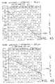
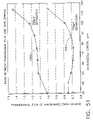
- microneedle arrays of the present inventionare significantly improved by using a proper separation distance between each of the individual microneedles.
- a very useful range of separation distances between microneedlesis in the range of 100-300 microns, and more preferably in the range of 100-200 microns.
- the outer diameter and microneedle lengthis also very important, and in combination with the separation distance will be crucial as to whether or not the microneedles will actually penetrate the stratum corneum of skin.
- a useful outer diameter rangeis from 20-100 microns, and more preferably in the range of 20-50 microns.
- a useful length for use with interstitial fluidsis in the range of 50-200 microns, and more preferably in the range of 100-150 microns; for use with other biological fluids, a useful length is in the range of 200 microns-3 mm, and more preferably in the range of 200-400 microns.
- a useful length for use with interstitial fluidsis in the range of 50-200 microns, and more preferably in the range of 80-150 microns: for use with other biological fluids, a useful length is again in the range of 200 microns-3 mm, and more preferably in the range of 200-400 microns.
- An example of a “sharp edge” as used hereinis where the tip of the blade edge exhibits a dimension at its angular vertex that is as narrow or narrower than 0.5 microns.
- a useful lengthis in the range of 50-200 microns, and more preferably in the range of 80-150 microns, while the radius of each of its blades is in the range of 10-50 microns, and more preferably in the range of 10-15 microns.
- the present inventioncan be manufactured with an alternative methodology using a mold preparation procedure that begins by placing an optical mask over a layer of PMMA material, then exposing the PMMA material that is not masked to x-rays or another type of high energy radiation (e.g., neutrons, electrons), and developing that PMMA material in a photoresist process.
- the remaining PMMA materialis then coated (e.g., electroplated) with metal, such as nickel. When the coating has reached the appropriate thickness, it is detached to become a metal mold to create polymer or other type of moldable plastic material.
- This metal moldis then used in a microembossing procedure, in which the metal mold is pressed against a heated layer of polymer or other plastic material.
- microneedlesare hollow, then alternative procedures to create through-holes all the way through the microneedles and its underlying substrate material uses a methodology such as, for example, laser ablation, water jet erosion, electric discharge machining, plasma etching, and particle bombardment.
- Another alternative procedure to create polymer or plastic microneedlesis to begin with a two-layer laminate structure of biocompatible material.
- a metallic mold created by any processis then pressed down all the way through the top layer of this laminate, and partially into the bottom layer to ensure that the top layer is entirely penetrated. This occurs while the laminate material has been heated to its plastic, deformable temperature.
- the moldis removed and the top layer is detached from the bottom layer.
- This top layerwill now have holes that will be further operated upon by a microembossing procedure using a different mold.
- This different moldcreates hollow microneedles, in which the through-holes that normally need to be later created in the substrate have already been created in advance by the first pressing or molding procedure.
- Another refinement of the present inventionis to create a microneedle array that has sensing capabilities.
- the tips or side grooves of the microneedlesare coated with a particular chemical that aids in detecting a particular chemical or biological structure or fluid that come into contact with the tips of the microneedles.
- a sensing meansis performed by the use of optical energy, for example such as a laser light source that is directed through the microneedle structure, in which the microneedles themselves are made of substantially transparent material. Other sensing mechanisms also could be used, as discussed hereinbelow.
- a further alternative manufacturing process for hollow or solid microneedlesis to create shear forces along the outer surfaces of the distal or tip portion of the hollow or solid microneedle during its molding or embossing process.
- the shear forcesare actually created during the de-molding step while the microneedle array material is being cooled.
- the amount of shearcan be controlled by the cool-down temperature, and if properly done will result in microneedles having sharp edges (rather than smooth edges) along their upper surfaces at their tips.
- FIG. 1is an elevational view in partial cross-section of a bottom mold provided at the initial step of a “self-molding” method of manufacturing an array of plastic microneedles, as constructed according to the principles of the present invention.
- FIG. 2is an elevational view in partial cross-section of the mold of FIG. 1 in a second step of the self-molding procedure.
- FIG. 3is an elevational view in partial cross-section of the mold of FIG. 1 in a third step of the self-molding procedure.
- FIG. 4is an elevational view in partial cross-section of the mold of FIG. 1 in a fourth step of the self-molding procedure.
- FIG. 5is an elevational view in partial cross-section of the mold of FIG. 1 in a fifth step of the self-molding procedure.
- FIG. 6is an elevational view in cross-section of an array of hollow microneedles constructed according to the self-molding procedure depicted in FIGS. 1-5 .
- FIG. 7is a cross-sectional view of a top mold-half used in a micromolding procedure, according to the principles of the present invention.
- FIG. 8is an elevational view of the bottom half of the mold that mates to the top mold-half of FIG. 7 , and which is used to form plastic microneedles according to the micromolding procedure.
- FIG. 9is an elevational view in partial cross-section of one of the method steps in the micromolding procedure using the mold halves of FIGS. 7 and 8 .
- FIG. 10is an elevational view in partial cross-section of the mold of FIG. 9 depicting the next step in the micromolding procedure.
- FIG. 11is a cross-sectional view of an array of plastic microneedles constructed according to the micromolding procedure depicted in FIGS. 7-10 .
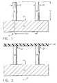
- FIG. 12is an elevational view in partial cross-section of a top mold-half and a bottom planar surface used in creating an array of molded, plastic microneedles by a microembossing procedure, as constructed according to the principles of the present invention.
- FIG. 13is an elevational view in partial cross-section of the mold of FIG. 12 in a subsequent process step of the microembossing method.
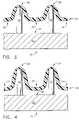
- FIG. 14is an elevational view in partial cross-section of the mold if FIG. 12 showing a later step in the microembossing procedure.
- FIG. 15is a cross-sectional view of a microneedle array of hollow microneedles constructed by the mold of FIGS. 12-14 .
- FIG. 15Ais a cross-sectional view of an array of microneedles which are not hollow, and are constructed according to the mold of FIGS. 12-14 without the micropillars.
- FIG. 16is an elevational view in partial cross-section of a two-piece mold used in a microinjection method of manufacturing plastic microneedles, as constructed according to the principles of the present invention.
- FIG. 17is a cross-sectional view of a microneedle array of hollow microneedles constructed by the mold of FIG. 16 .
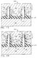
- FIG. 18is a cross-sectional view of the initial semiconductor wafer that will be formed into an array of microneedles by a microfabrication procedure, according to the principles of the present invention.
- FIG. 19is a cross-sectional view of the semiconductor wafer of FIG. 18 after a hole pattern has been established, and after a silicon nitride layer has been deposited.
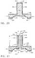
- FIG. 20is a cross-sectional view of the wafer of FIG. 18 after a photoresist mask operation, a deep reactive ion etch operation, and an oxidize operation have been performed.
- FIG. 21is a cross-sectional view of the wafer of FIG. 20 after the silicon nitride has been removed, and after a deep reactive ion etch has created through holes, thereby resulting in a hollow microneedle.
- FIG. 22is a perspective view of a microneedle array on a semiconductor substrate, including a magnified view of individual cylindrical microneedles.
- FIG. 23is a cross-sectional view of an electrophoretically enhanced body-fluid sensor, based upon a hollow microneedle array, as constructed according to the principles of the present invention.
- FIG. 24is a cross-sectional view of an electrophoretically enhanced body-fluid sensor, based upon a solid microneedle array, as constructed according to the principles of the present invention.
- FIG. 25is a cross-sectional view of an electrode, based upon a hollow microneedle array, as constructed according to the principles of the present invention.
- FIG. 26is a cross-sectional view of an electrode, based upon a solid microneedle array, as constructed according to the principles of the present invention.
- FIG. 27is a perspective view of a sensing system attached to a human hand and forearm, which includes an electrophoretically enhanced body-fluid sensor as per FIG. 23 and an electrode as per FIG. 25 .
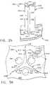
- FIG. 28is a cross-sectional view of an electrophoretically enhanced drug delivery system, based upon a hollow microneedle array, as constructed according to the principles of the present invention.
- FIG. 29is a cross-sectional view of an electrophoretically enhanced drug delivery system, based upon a solid microneedle array, as constructed according to the principles of the present invention.
- FIG. 30is a perspective view of a closed-loop drug-delivery system, as viewed from the side of a patch that makes contact with the skin, as constructed according to the principles of the present invention.
- FIG. 31is a perspective view of the closed-loop drug-delivery system of FIG. 30 , as seen from the opposite side of the patch.
- FIG. 32is a perspective view of an alternative embodiment hollow microneedle having sharp edges for greater penetration into skin.
- FIG. 33is a top plan view of the edged hollow microneedle of FIG. 32 .
- FIG. 34is a perspective view of an alternative construction for an edged hollow microneedle as seen in FIG. 32 .
- FIG. 35is a perspective view of an alternative embodiment solid microneedle having a star-shaped set of sharp blades.
- FIG. 36is a top plan view of the star-shaped solid microneedle of FIG. 35 .
- FIG. 37is a table of microneedle penetration data for an array of circular hollow microneedles at a separation distance of 50 microns.
- FIG. 38is a table of microneedle penetration data for an array of circular hollow microneedles at a separation distance of 100 microns.
- FIG. 39is a table of microneedle penetration data for an array of circular hollow microneedles at a separation distance of 150 microns.
- FIG. 40is a table of microneedle penetration data for an array of circular hollow microneedles at a separation distance of 200 microns.
- FIG. 41is a table of microneedle penetration data for an array of circular hollow microneedles at a separation distance of 250 microns.
- FIG. 42is a table of microneedle penetration data for an array of circular hollow microneedles at a separation distance of 300 microns.
- FIG. 43is a table of microneedle penetration data for an array of edged hollow microneedles at a separation distance of 50 microns.
- FIG. 44is a table of microneedle penetration data for an array of edged hollow microneedles at a separation distance of 100 microns.
- FIG. 45is a table of microneedle penetration data for an array of edged hollow microneedles at a separation distance of 150 microns.
- FIG. 46is a table of microneedle penetration data for an array of edged hollow microneedles at a separation distance of 200 microns.
- FIG. 47is a table of microneedle penetration data for an array of edged hollow microneedles at a separation distance of 250 microns.
- FIG. 48is a table of microneedle penetration data for an array of edged hollow microneedles at a separation distance of 300 microns.
- FIG. 49is a graph showing the effect of microneedle separation versus transdermal flux.
- FIG. 50is a graph showing the effect of microneedle length versus transdermal flux for two different microneedle separation distances.
- FIG. 51is a graph showing the effect of microneedle length versus a ratio of transdermal flux versus skin damage, for two different microneedle separation distances.
- FIG. 52is a graph showing the effect of applied pressure of a fluid versus transdermal flux for a particular microneedle array.
- FIGS. 53A-53Eare elevational views in cross-section illustrating steps for preparing a mold for a micromolding procedure to create hollow circular microneedles.
- FIGS. 54A-54Fare elevational views in cross-section of process steps for a microembossing procedure to create hollow microneedles, as well as micromachininc and laser burning steps to create hollow chambers and through-holes in the bottom of the substrate structure.
- FIGS. 55A-55Fare elevational views in cross-section of further process steps for creating hollow microneedles.
- FIG. 56A-56Bare an elevational views in cross-section of microneedle arrays that have sensing capabilities using optical devices or chemical coatings.
- FIGS. 57A-57Bare side elevational views of a de-molding procedure to create sharp hollow microneedles.
- FIG. 1shows a mold generally designated by the reference numeral 10 that comprises a plurality of micropillars, including micropillars 12 and 14 , that are mounted to a base 16 having a planar upper surface 18 .
- Micropillar 12preferably is cylindrical in shape, and has an outer diameter designated “D 1 ,” whereas micropillar 14 (which also preferably is cylindrical in shape) has a diameter designated “D 2 .”
- the centerlines of micropillars 12 and 14are separated by a distance “D 3 ,” and the vertical height of micropillars 12 and 14 is designated by the letter “L 1 .”
- Microelectrode-discharge machiningcan be used to fabricate the mold 10 from metals, such as stainless steel, aluminum, copper, iron, tungsten, or other metal alloys. Mold 10 could also be fabricated from silicon or silicon carbide using integrated circuit processing, or photolithographic processing.
- FIG. 2depicts the mold 10 and a thin layer of plastic, such as a polymer film, designated by the reference numeral 20 , which is placed on the micropillars 12 and 14 , thereby making contact at the reference numerals 22 and 24 , respectively.
- a polymer filmdesignated by the reference numeral 20
- the polymeris heated to just above the melting temperature of the plastic material.
- Micropillars 12 and 14are heated to above the glass transition temperature of the plastic material, but are preferably held below the melting temperature of the plastic material. This establishes a temperature gradient within the plastic film, after which the plastic film is subjected to natural gravitational forces, or placed in a centrifuge.
- an air-pressure gradientalso can be established across the deforming plastic film, by applying pressure from above, or by applying a vacuum from below the film level.
- the overall effect on the plastic filmis that it will undergo a “self-molding” operation, by way of the gravitational force or centrifugal force, and the air-pressure gradient can be used to accelerate the self-molding process.
- FIG. 3depicts the mold 10 at a further step in the processing of the plastic film, showing the result of the temperature gradient.
- This resultis that the areas contacting the micropillars (at the reference numerals 22 and 24 ) will have a smaller deformation as compared to the remaining portions of the plastic film 20 that are between the pillars 12 and 14 . Therefore, the portions 30 , 32 , and 34 of the plastic material will undergo greater deformation, as viewed on FIG. 3 .
- FIG. 4depicts the mold 10 at yet a later step in the self-molding process, showing the initial stage in which the mold (including micropillars 12 and 14 ) is heated above the melting temperature of the plastic material 20 .
- the plastic materialwill continue to melt and to be removed from the tops of the pillars 12 and 14 .
- the remaining portions not in contact with micropillars 12 and 14will continue to deform downward (as viewed on FIG. 4 ) at the reference numerals 30 , 32 , and 34 .
- FIG. 5depicts the mold 10 at the final stage of self-molding, which illustrates the fact that the plastic material has completely melted down and away from the tops 22 and 24 of the micropillars 12 and 14 .
- the mold and the plastic materialare both cooled down, thereby forming the final shape that will become the microneedles.
- This final shapeincludes an outer wall 40 and 42 for the microneedle being formed by micropillar 12 , and an outer wall at 44 and 46 for the microneedle being formed at the micropillar 14 .
- FIG. 6illustrates the cross-sectional shape of the microneedle array, generally designated by the reference numeral 60 , after it has been detached from the mold 10 .
- the left hand microneedle 62has a relatively sharp upper edge, which appears as points 50 and 52 .
- Its outer wallis illustrated at 40 and 42 , which are sloped with respect to the vertical, as designated by the angles “A 1 ” and “A 2 .”
- the right-hand side microneedle 64exhibits a similar sharp top edge, as indicated by the points 54 and 56 , and also exhibits a sloped outer wall at 44 and 46 .
- the angle of this outer wallis indicated at the angles “A 3 ” and “A 4 .”
- the preferred value of angles A 1 -A 4is in the range of zero (0) to forty-five (45) degrees.
- the inner diameter of the left-hand microneedle 62is indicated by the distance “D 1 ,” and the inner diameter of the right-hand microneedle 64 is indicated by the distance “D 2 .”
- These distances D 1 and D 2are substantially the same distance as the diameter of micropillars 12 and 14 , as indicated in FIG. 1 .
- the distance D 3 between the centerlines of the microneedles on FIG. 6is essentially the same as the distance D 3 between the micropillars on FIG. 1 .
- the length “L 2 ” of the microneedles on FIG. 6is somewhat less than the length L 1 on FIG. 1 , although this length L 2 could theoretically be a maximum distance of L 1 .
- the plastic materialmay consist of any type of permanently deformable material that is capable of undergoing a gradual deformation as its melting point is reached or slightly exceeded.
- This “plastic material”could even be some type of metallic substance in a situation where the metallic material would deform at a low enough temperature so as to not harm the mold itself.
- the preferred materialis a polyamide such as nylon, although many other types of polymer material certainly could be used to advantage.
- polyestersvinyls, polystyrenes, polycarbonates, acrylics such as PMMA, polyurethanes, epoxides, phenolics, and acrylonitriles like acrylonitrilebutadienestyrene (ABS).
- acrylicssuch as PMMA
- polyurethanespolyurethanes
- epoxidesepoxides
- phenolicsepoxides
- ABSacrylonitriles like acrylonitrilebutadienestyrene
- FIG. 7depicts a top mold-half, generally designated by the reference numeral 110 , of a second embodiment of the present invention in which the manufacturing method for creating an array of hollow microneedles is performed by a micromolding procedure.
- the top mold-half 110includes two “microholes” that have sloped side walls, designated by the reference numerals 112 and 114 for the left-hand microhole 113 , and by the reference numerals 116 and 118 for the right-hand microhole 117 .
- the microholes 113 and 117have a vertical (in FIG. 7 ) dimension referred to herein as a distance “L 11 ”.
- Microholes 113 and 117correspond to a pair of micropillars 122 and 124 that are part of a bottom mold-half, generally designated by the reference number 120 , and illustrated in FIG. 8 .
- the sloped side walls of the microhole 113are depicted by the angles “A 11 ” and “A 12 ,” with respect to the vertical.
- the side walls of microhole 117are also sloped with respect to the vertical, as illustrated by the angles “A 13 ” and “A 14 ” on FIG. 7 .
- microhole 113preferably is in a conical overall shape, the angle All will be equal to the angle A 12 ; similarly for microhole 117 , the angle A 13 will be equal to the angle A 14 . It is preferred that all microholes in the top mold-half 110 exhibit the same angle with respect to the vertical, which means that angles A 11 and A 13 are also equal to one another.
- angles A 11 -A 14is in the range of zero (0) through forty-five (45) degrees. The larger the angle from the vertical, the greater the trauma to the skin tissue when a microneedle is pressed against the skin. On FIG. 7 , the illustrated angle A 11 is approximately twelve (12) degrees.
- the bottom mold-half 120includes a base 126 having a substantially planar top surface 128 , upon which the two micropillars 122 and 124 are mounted.
- These micropillarsare preferable cylindrical in shape, and have a diameter of D 11 and D 12 , respectively.
- the distance between the centerlines of these micropillarsis designated as D 13 .
- Diameters D 11 and D 12preferably are in the range 1-49 microns, more preferably about 10 microns.
- the distance “D 13 ”represents the separation distance between the center lines of micropillars 122 and 124 , which preferably is in the range 50-1000 microns, more preferably in the range of 100-200 microns.
- the two mold-halves 110 and 120can be fabricated from metals using microelectrode-discharge machining techniques. Alternatively, the molds could be fabricated from silicon or silicon carbide using integrated circuit processing or lithographic processing.
- a thin plastic filmis placed on top of the micropillars and heated above the glass transition temperature of the plastic material while the plastic material 130 rests upon the tops of the pillars at 132 and 134 , thereby causing the plastic material to become sufficient pliable or “soft” for purposes of permanently deforming the material's shape.
- the temperature of the plastic materialwill not be raised above its melting temperature, although it would not inhibit the method of the present invention for the plastic material to become molten just before the next step of the procedure.
- the top mold-half 110is pressed downward and begins to deform the plastic film 130 .
- the two mold halves 110 and 120are aligned so that the microholes 113 and 117 correspond axially to the micropillars 122 and 124 , respectively.
- the two mold halvesnow begin to operate as a single mold assembly, generally designated by the reference numeral 100 .
- the two mold halves 110 and 120have completely closed, thereby squeezing all of the plastic material 130 away from the tops of the micropillars 122 and 124 .
- the plastic microneedlesare formed, and the mold and the plastic material are both cooled down.
- the wall 112 and 114 of the first microhole 113causes a side outer wall to be formed out of the plastic material at 150 and 152 .
- the corresponding inner wall of the microneedle 182is depicted at 160 and 162 , which is caused by the shape of the micropillar 122 . Since the outer wall is sloped, it will converge with the inner wall 160 and 162 , near the top points at 170 and 172 .
- a similar outer wall 154 and 156is formed by the inner wall 116 and 118 of microhole 117 .
- the inner wall of the microneedle 184is depicted at 164 and 166 , and these inner and outer walls converge near points 174 and 176 .
- FIG. 11illustrates the microneedle array, generally designated by the reference numeral 180 , after the mold is removed from the plastic material 130 .
- a lower relatively planar baseremains, as illustrated at 140 , 142 , and 144 .
- two different microneedlesare formed at 182 and 184 .
- the angles formed by the wallsare as follows: angle A 11 by walls 150 and 160 , angle A 12 by walls 162 and 152 , angle A 13 by walls 154 and 164 , and angle A 14 by walls 166 and 156 .
- the points at the top if the microneedles(designated at 170 , 172 , 174 , and 176 ) are fairly sharp, and this sharpness can be adjusted by the shape of the mold with respect to the microholes and micropillar orientations.
- microneedle 182The inner diameter of microneedle 182 is designated by the distance D 11
- the inner diameter of the microneedle 184is designated by the distance D 12
- the distance between the centerlines of these microneedlesis designated as D 13 . These distances correspond to those illustrated on FIG. 8 .
- angles A 11 -A 14are equal to one another, and that the angles fall within the range of zero (0) to forty-five (45) degrees.
- the preferred anglereally depends upon the strength of the material being used to construct the microneedles, in which a greater angle (e.g., angle A 11 ) provides greater strength. However, this angular increase also causes greater trauma to the skin.
- Microneedle array 180also includes a relatively flat base structure, as indicated at the reference numerals 140 , 142 , and 144 .
- This base structurehas a vertical thickness as designated by the dimension L 15 (see FIG. 11 ).
- the microneedle heightis designated by the dimension L 12 on FIG. 11 .
- the heightmust be sufficient to penetrate the skin through the stratum corneum and into the epidermis, and a preferred dimension for height L 12 is in the range of 50-3000 microns (although, certainly microneedles shorter than 50 microns in length could be constructed in this manner—for use with skin cosmetics, for example).
- the thickness L 15can be of any size, however, the important criterion is that it be thick enough to be mechanically sound so as to retain the microneedle structure as it is used to penetrate the skin.
- a top mold-half 210is combined with a planar bottom mold-half 240 to create an entire mold, generally designated by the reference numeral 200 .
- the top mold-half 210contains an array of microholes with micropillars at the center of each of the microholes.
- a microhole 213having its conical wall at 212 and 214 , is preferably concentric with a micropillar 222
- a microhole 217having its conical wall at 216 and 218 , is preferably concentric with a micropillar 224 .
- microembossingThe fabrication method used in conjunction with the mold 200 is referred to herein as “microembossing” for the reason that the bottom mold-half 240 is simply a flat or planar surface. This greatly simplifies the construction of this particular mold.
- a thin plastic film at 230is placed upon the top surface 242 of this bottom mold-half 240 . In the later steps, it will be seen that the plastic material 230 is heated while the top mold-half 210 is pressed down against the bottom mold-half 240 .
- Microhole 213 and micropillar 222have an angular relationship as illustrated by the angles “A 21 ” and “A 22 .”
- These angles A 21 -A 24will preferably be in the range of zero (0) to forty-five (45) degrees from the vertical.
- the greater the anglethe greater the transport rate, however, also the greater trauma to the skin tissue when used.
- Micropillar 222preferably has a cylindrical shape with an outer diameter designated at “D 21 .” and micropillar 224 similarly has a preferred cylindrical shape having a diameter “D 22 .” Diameters D 21 and D 22 preferably are in the range 1-49 microns, more preferably about 10 microns. The distance “D 23 ” represents the separation distance between the center lines of micropillars 222 and 224 , which preferably is in the range 50-1000 microns, more preferably in the range of 100-200 microns.
- the length of the micropillars from the bottom surface 228 of the top mold-half 210 to the closed end of the microholes at 215 and 225 , respectively,is designated as the length “L 21 .”
- the micropillars 222 and 224are somewhat longer than this length L 21 , since they are to mate against the upper surface 242 of the bottom mold-half 240 , and therefore are longer by a distance designated as “L 25 .” In this manner, the microneedles will be hollow throughout their entire length.
- the combined length of dimensions L 21 and L 25preferably will be approximately 150 microns.
- the molds 210 and 240will preferably be made from a metal, in which microelectrode-discharge machining can be used to fabricate such metallic molds.
- the moldscould be fabricated from silicon or silicon carbide, for example, using integrated circuit processing or lithographic processing.
- the temperature of the plastic materialwill not be raised above its melting temperature, although it would not inhibit the method of the present invention for the plastic material to become molten just before the top mold 210 begins to be pressed down against the plastic material 230 .
- This top mold movementbegins to deform that plastic material 230 such that it begins to fill the microholes, as illustrated at 232 and 234 (for microhole 213 ) and at 236 and 238 (for microhole 217 ).
- the top mold-half 210has now been completely closed against the bottom planar mold-half 240 , and the plastic material 230 has now completely filled the microholes, as illustrated at 232 , 234 , 236 , and 238 .
- the shape of the plastic materialnow has a conical outer wall at 250 and 252 , and a corresponding cylindrical inner wall at 260 and 262 , for the left-hand microneedle 282 on FIG. 14 .
- the plastic material shapehas an outer conical wall at 254 and 256 , as well as a cylindrical inner wall at 264 and 266 .
- the conical outer walls and the cylindrical inner wallsconverge at the top points 270 and 272 , and 274 and 276 .
- the bottom surface 228 of the top mold-half 210causes a base to be formed in the plastic material 230 at the locations indicated by the reference numerals 244 , 246 , and 248 .
- a microneedle array 280has been formed out of the plastic material 230 , which as viewed on FIG. 15 depicts two microneedles 282 and 284 .
- the left-hand microneedle 282comprises an outer conical wall as viewed at 250 and 252 , and a hollow interior cylindrical wall at 260 and 262 . These walls converge at the top points (as viewed on this Figure) at 270 and 272 , and the convergence angle is given as “A 21 ” and “A 22 .”
- the right-hand microneedle 284comprises an outer conical wall 254 and 256 and a hollow interior cylindrical wall 262 and 264 .
- Angles A 21 -A 24are preferably in the range of zero (0) to forty-five (45) degrees.
- Microneedle array 280also includes a relatively flat base structure, as indicated at the reference numerals 244 , 246 , and 248 .
- This base structurehas a vertical thickness as designated by the dimension L 25 .
- the microneedle heightis designated by the dimension L 22 .
- the heightmust be sufficient to penetrate the skin through the stratum corneum and into the epidermis, and has a preferred dimension for use with interstitial fluids in the range of 50-200 microns (although, as noted above, much shorter microneedles could be constructed in this manner).
- the height L 22could also be a greater distance for use with other biological fluids, preferably in the range of 200-3000 microns.
- the thickness L 25can be of any size, however, the important criterion is that it be thick enough to be mechanically sound so as to retain the microneedle structure as it is used to penetrate the skin.
- the inside diameter of the hollow microneedlesis illustrated as D 21 and D 22 , which correspond to the diameters of a cylindrical hollow opening.
- the distance D 23represents the separation distance between the centerlines of the two microneedles 282 and 284 , in this array 280 .
- FIG. 15Arepresents an alternative embodiment in which a microneedle array 290 comprises “solid” microneedles 292 and 294 , rather than hollow microneedles as seen at 282 and 284 on FIG. 15 .
- These solid microneedles 292 and 294are formed by a similar mold as viewed on FIG. 12 , but with the micropillars 222 and 224 removed from this mold, and a change in shape of the microholes 213 and 217 .
- This simple changeallows the solid microneedles to be formed within conical microholes (not shown on FIG. 12 ), and produces a pointed conical shape, as exhibited by the outer conical wall 250 and 252 for microneedle 292 , with a top pointed surface at 296 .
- microneedle 294has a conical outer wall 254 and 256 , with a similar top pointed surface at 298 .
- the other dimensions and features of the solid microneedle array 290can be exactly the same as those features of the hollow microneedle array 280 of FIG. 15 , or the dimensions may be different since this is for a different application.
- the holes 251 , 253 , 255can be fabricated during the microstamping or microembossing procedure via inclusion of appropriate micropillars located adjacent to the microholes 213 and 217 in FIG. 12 .
- a mold 300consists of two mold-halves 310 and 340 . These mold-halves 310 and 340 are virtually identical in shape, and probably in size, as compared to the mold-halves 210 and 240 of the mold 200 on FIG. 12 .
- the main difference in FIG. 16is that these mold-halves are to be used in a microinjection procedure in which molten plastic material is injected from the side at 330 into the opening between the mold-halves formed by the bottom surface 328 of the top mold-half 310 and the top surface 342 of the bottom mold-half 340 .
- the mold structure 300is preferably made of a metallic material by a micro-machining process, although it could be made of a semiconductor material such as silicon or silicon carbide, if desired.
- the plastic material 330is being filled from the left-hand side in this view, and has already filled a first microhole 313 with plastic material.
- the plastic materialis illustrated as it is advancing, and has reached the point at the reference numeral 336 .
- the plastic materialwill reach and fill the second microhole 317 , which has a conical inner wall at 316 and 318 , and a corresponding micropillar 324 .
- the plastic materialhas filled the shape around a micropillar 322 and within the conical walls of this microhole 313 , to form a hollow cone having an outer wall at 332 and 334 .
- the plastic materialwill be forced upward until it reaches a top point as seen at the reference numerals 370 and 372 .
- the outer conical shape at 332 and 334will converge with the interior shape of the micropillar 322 at an angle designated by the angles “A 31 ” and “A 32 .”
- Microhole 317also exhibits a converging angular shape at “A 33 ” and “A 34 ,” which is the convergence angle between the conical walls 316 and 318 and the outer cylindrical shape of the micropillar 324 .
- the separation between the surfaces 328 and 342is given by the length dimension “L 35 ,” which will become the thickness of the planar face material that will remain once the mold is opened.
- the vertical dimension (in FIG. 16 ) of the microholesis given by the dimension “L 31 ” which preferably will create microneedles long enough to penetrate through the stratum corneum and into the epidermis, but not so long as to penetrate all the way to the dermis when used with interstitial fluids.
- the microneedle lengthwill be greater, preferably in the range of 200-3000 microns, so as to penetrate into the dermis.
- FIG. 17illustrates the microneedle array, generally designated by the reference numeral 380 .
- two microneedlesare illustrated at 382 and 384 .
- These microneedleshave a length “L 32 ,” which in theory should be exactly the same as the dimension L 31 on FIG. 16 , assuming the mold was properly filled with material.
- a preferred distance for L 32is in the range of 50-200 microns.
- the plastic material 330has a planar base structure, as illustrated at 344 , 346 , and 348 .
- the thickness of this base structureis the dimension L 35 .
- the microneedlesthemselves exhibit a conical outer wall at 350 and 352 for the left-hand microneedle 382 , and at 354 and 356 for the right-hand microneedle at 384 .
- Each microneedlehas a hollow interior, as illustrated by the cylindrical surface 360 and 362 for microneedle 382 , and 364 and 366 for microneedle 384 . These surfaces converge to form points (as illustrated on FIG. 17 ) at 370 and 372 for microneedle 382 , and at 374 and 376 for microneedle 384 .
- the convergence angle of these wallsis designated by the angles A 31 -A 34 , and preferably will be in the range of zero (0) to forty-five (45) degrees.
- microneedle 382The inner diameter of microneedle 382 is given by the dimension D 31 , and for microneedle 384 is given by dimension D 32 . These dimensions preferably are in the range 1-49, more preferably about 10 microns.
- the separation distance between the center lines of the microneedlesis given at D 33 , which preferably is in the range 50-1000 microns, more preferably in the range of 100-200 microns.
- the height L 32is preferably in the range of 50-3000 microns and, depending upon the convergence angle A 31 -A 34 , the bottom width of the conical microneedles will vary depending upon the exact application for usage. In one preferred embodiment, this bottom dimension, designated by “D 34 ” and “D 35 .” will be approximately twenty (20) microns.
- the vertical thickness at L 35will likely be made as thin as possible, however, the important criterion is that it is sufficiently thick to be mechanically sound to hold the microneedle array 380 together as a single structure during actual usage. It is likely that, for most plastic materials that might be used in this molding procedure, the dimension L 35 will be in the range of ten (10) microns through two (2) mm, or greater.
- microneedles 62 , 64 and planar surfaces 30 , 32 , 34 of FIG. 6are preferably perpendicular, although an exact right angle of 90 degrees is not required.
- microneedles 182 , 184 and planar surfaces 140 , 142 , 144 of FIG. 11are preferably perpendicular, although an exact right angle of 90 degrees.
- microneedles 282 , 284 and planar surfaces 244 , 246 , 248 of FIG. 15microneedles 292 , 294 and planar surfaces 244 , 246 , 248 of FIG. 15A
- microneedles 382 , 384 and planar surfaces 344 , 346 , 348 of FIG. 17are microneedle 470 and planar surfaces 440 , 446 of FIG. 21 .
- plastic microneedlescould be utilized to create hollow microneedles in an array, without departing from the principles of the present invention. It will also be understood that various types of materials could be used for such molding procedures, including metallic materials that might be cast using higher temperature dies of a similar shape and size, without departing from the principles of the present invention.
- microneedlescould be utilized to construct an array of hollow microneedles, without departing from the principles of the present invention. It will be still further understood that the angular relationship between the microneedles and their planar base surface need not be precisely perpendicular (although that configuration is preferred), but could have some variation without departing from the principles of the present invention; the microneedles also need not be exactly parallel with one another, even though that configuration is preferred.
- microneedle shapescould be used than a cylindrical shape, if desired, without departing from the principles of the present invention.
- shape for hollow microneedlescould prescribe a circle, ellipse, square, triangle, crescent or other arcuate path, or some other geometric structure for either the inner opening or the outer perimeter.
- the inner opening's shapecould be different from the outer perimeter's shape.
- an array of solid microneedlescould be fabricated using the molding techniques described herein, without departing from the principles of the present invention.
- the outer shape for such solid microneedlescould prescribe a circle, ellipse, square, triangle, crescent or other arcuate path, a star or other jagged perimeter, or some other geometric structure.
- FIG. 18a procedure for forming dry etched microneedles will be described using an example of microfabrication (e.g., semiconductor fabrication) techniques.
- a single crystal silicon waferat reference numeral 400 , it is preferred to use a double side polish wafer and to grow an oxide layer on the entire outer surface.
- a cross-section of this waferappears as a substrate 410 , a top oxide layer 412 , and a bottom oxide layer 414 .
- Any single crystal silicon waferwill suffice, although it is preferred to use a crystal structure 100-type wafer, for reasons that will be explained below.
- a 110-type wafercould be used, however, it would create different angles at certain etching steps.
- the first stepis a pattern oxide step which is performed on the top side only to remove much of the top oxide layer 412 .
- the pattern usedwill create multiple annular regions comprising two concentric circles each, of which the cross-section will appear as the rectangles 416 and 418 on FIG. 19 .
- these annular-shaped featureswill have the appearance as illustrated on the perspective view of FIG. 22 at the reference numerals 416 and 418 .
- These annular oxide patternsare the initial stages of the array locations of the multiple microneedles that will be formed on this substrate 410 .
- the next stepis to deposit a layer of silicon nitride using a low pressure vapor deposition step, which %%ill form a silicon nitride layer on both the top and bottom surfaces of the substrate 410 .
- the bottommost layer 422 and 424is one continuous layer at this step, although it is not illustrated as such on FIG. 19 , since a later step etches out a portion of the bottom side of the substrate between the layers 422 and 424 .
- a pattern bottom procedurein which a square hole is patterned beneath the annulus 416 , 418 , which is not directly visible on FIG. 19 .
- the square holes placed by the pattern bottom procedureare now used in a KOH etching step that is applied to the bottom side only of the substrate 410 .
- This KOH etching stepcreates a window along the bottom of the substrate as viewed along the surfaces 432 , 430 , and 434 on FIG. 19 .
- This windowinterrupts the oxide layer 414 along the bottom of substrate 410 , and divides it (on FIG. 19 ) into two segments 413 and 415 .
- This window (or hole)also interrupts the silicon nitride layer into two segments (on FIG. 19 ) 422 and 424 .
- the slope angle of the etched window along surfaces 432 and 434is 54.7 degrees, due to the preferred 100-type silicon material. If type-110 silicon material was used, then this slope would be 90 degrees. That would be fine, however, crystalline silicon 100-type material is less expensive than silicon 110-type material.
- the next fabrication operationis to perform a pattern top nitride procedure using a photoresist mask. This removes the entire upper silicon nitride layer 420 except where the photoresist mask was located, which happens to be aligned with the upper oxide annulus at 416 and 418 .
- the remaining upper silicon nitrideis indicated at the reference numeral 426 on FIG. 20 , although at this stage in the fabrication procedure, the upper surface will still be a planar surface at the level of the oxide layer 416 and 418 , across the entire horizontal dimension of FIG. 20 .
- the next fabrication stepis to perform a deep reactive ion etch (DRIE) operation on the top surface of the substrate 410 , which will etch away a relatively deep portion of the upper substrate except at locations where the silicon nitride layer still remains, i.e., at 426 .
- DRIEdeep reactive ion etch
- the next fabrication stepis to oxidize all of the bare silicon that is now exposed along the outer surfaces. This will form a layer of silicon dioxide at locations on FIG. 20 , such as at 440 , 442 , 444 , 446 , 452 , 450 , and 454 .
- the outer silicon nitride layers at 426 , 423 , and 425are not oxidized.
- the outer silicon nitride layers 423 and 425are essentially the same structures as layers 422 and 424 on FIG. 19 , although the silicon dioxide layers 452 and 454 are now formed above these “pads” 423 and 425 .
- this oxidationbe a minimal amount, just enough for a future DRIE masking procedure, and that the oxidized thickness be approximately 5,000 Angstroms.
- the silicon waferhas the appearance of that depicted in FIG. 20 .
- the next step in the fabrication procedureis to remove the silicon nitride layer on the top, which will remove the layer at 426 as seen on FIG. 20 . This will expose a circular region in the very center of the annulus such that pure silicon is now the outermost material on the top side of the wafer. After that has occurred, a deep reactive ion etch operation is performed to create a through-hole at the reference numeral 460 on FIG. 21 . After this step has been performed, there will be pure silicon exposed as the inner wall of the through-hole 460 . Therefore, the next step is to oxidize the entire wafer, which will place a thin cylindrical shell of silicon dioxide around the inner diameter of through-hole 460 , and this oxidized layer is viewed on FIG. 21 at 462 and 464 .
- a microneedle 465is the result, having an outer diameter at “D 41 ,” and an inner diameter through-hole at “D 42 .” It is preferred that the inner diameter D 42 have a distance in the range of 5-10 microns.
- the height of the microneedleis given at the dimension “L 41 ,” which has a preferred dimension in the range of 50-200 microns.
- the substrate 410has been divided into halves at 410 A and 410 B.
- the bottom oxide layer 450has been divided in halves at 450 A and 450 B.
- This chamber 470can be used to store a fluid, such as insulin, that is to be dispensed through the cylindrical opening 460 in the hollow microneedle 465 .
- this chamberis not very large in overall physical volume, and it normally would be preferred to interconnect all of such chambers for each of the microneedles in the overall array so that a common fluid source could be used to dispense fluid to each of these chambers 470 .
- microneedlesthere may be a need to dispense a physically much larger volume of fluid, and it also may be desirable to provide a pressure source, such as a pump. In such situations, it may be preferable to have an external storage tank that is in communication with each of the fluid chambers 470 on the wafer that is used to make up the array of microneedles, such as microneedle 465 .
- FIG. 22depicts an array of microneedles on substrate 410 , and also illustrates a magnified view of some of these microneedles 465 .
- Each microneedle 465exhibits a cylindrical shape in the vertical direction, and has an outer diameter D 41 , an annular shaped upper surface at 416 and 418 , and a through-hole at 460 .
- Each of the microneedles 465extends out from the planar surface 440 of the substrate 410 .
- substrate 410can either be made much larger in height so as to have a very large internal volume for holding a fluid substance, or the substrate itself could be mounted onto a different material that has some type of fluidic opening that is in communication with the chambers 470 of the individual microneedles 465 .
- microneedlescould be coated with materials such as silicon carbide to impart additional strength.
- other microneedle shapescould be used than a cylindrical shape with an annular top surface, and in fact, the top surface of such microneedles could be sloped to create a sharper edge, if desired, without departing from the principles of the present invention.
- microneedle length or diameterthat is appropriate for a particular chemical fluidic compound and for a particular skin structure could be used without departing from the principles of the present invention.
- the microneedlepenetrate through the stratum corneum into the epidermis, but not penetrate into the dermis itself. This means that'such microneedles would typically be no longer than two hundred (200) microns, though they must typically be at least fifty (50) microns in length.
- a useful lengthis in the range of 200 microns—3 mm, and more preferably in the range of 200-400 microns.
- microneedlecould be much shorter in length, even as short as one (1) micron.
- any size or shape of fluid-holding chambercould be used in a drug-delivery system, which will be further discussed hereinbelow.
- a fluid-holding chamberwould also preferably be in communication with the through-holes 460 of each of the microneedles 465 .
- FIG. 23depicts an electrophoretically enhanced body-fluid sensor that is based upon a hollow microneedle array, generally designated by the reference numeral 500 .
- Sensor 500includes a plurality of microneedles 530 , which are each hollow, having a vertical opening throughout, as indicated at 532 .
- a fluid chamber 510is in communication with the hollow portions 532 of the array of microneedles 530 .
- other fluid driving mechanismscould be used as well, such as passive diffusion (e.g., time release), instantaneous injection, pressure, vacuum, or ultrasound.
- Fluid chamber 510is constructed of a bottom (in FIG. 23 ) planar surface 512 —which has openings that are aligned with the microneedles 530 —a left vertical wall 514 , and a right vertical wall 516 .
- the top (or ceiling) of the fluid chamber 510is made up of a planar material which is divided into individual electrodes.
- the middle electrode 525is part of the fluid sensor, and makes it possible to measure a current or voltage within the fluid chamber 510 .
- Electrodes 520 and 522are electrically connected to one another (and can be of a single structure, such as an annular ring) so as to act as the electrophoretic electrodes (i.e., as either an anode or a cathode) that facilitate the transport of fluid through the hollow microneedles 530 from the skin into the fluid chamber 510 .
- the height of the fluid chamber structureis designated as “L 50 ,” which could be any reasonable dimension that is large enough to hold a sufficient volume of fluid for a particular application.
- the fluid chamber 510could be connected to a much larger external reservoir (not shown), and a pump could even be used if pressure or vacuum is desired for a particular application.
- the layer 540represents the stratum corneum
- the layer 542represents the viable epidermis
- the largest layer 544represents the dermis, which contains nerves and capillaries.
- microneedles 530 into the stratum corneum 540 and epidermis 542decreases the electrical resistance of the stratum corneum by a factor of approximately fifty (50).
- the applied voltagetherefore, during electrophoresis (e.g., iontophoresis) or electroosmosis can be greatly reduced, thereby resulting in low power consumption and improved safety.
- Iontophoresisprovides the necessary means for molecules to travel through the thicker dermis into or from the body.
- the combination of the microneedles and the electric field that is applied between the electrodes 520 and 522 (acting as an anode, for example) and a remotely placed electrode (e.g., electrode assembly 505 , viewed on FIG. 25 , and acting as a cathode, for example)provides for an increase in permeability for both the stratum corneum and the deeper layers of skin.
- the electrophoresisprovides higher transport rates in the epidermis and dermis. This is not only true for small sized molecules, but also for the larger and more complex useful molecules.
- the body-fluid sampling sensor 500can be used for a continuous non-invasive measurement of blood glucose level, for example.
- Glucoseis extracted through the skin by reverse iontophoresis, and its concentration is then characterized by a bioelectrochemical sensor.
- the sensorcomprises the chamber 510 that is filled with hydrogel and glucose oxidase, and the electrode 525 .
- the glucose moleculesare moved from the body by the flow of sodium and chloride ions caused by the applied electric potential.
- the detection of the glucose concentration in the hydrogel padis performed by the bioelectrochemical sensor.
- FIG. 24An alternative embodiment 550 is depicted in FIG. 24 , in which the microneedles 580 are solid, rather than hollow.
- a fluid-filled chamber 560is provided and also comprises hydrogel filled with glucose oxidase.
- the chamber 560is made of a bottom wall 562 that has openings proximal to the individual microneedles 580 , in which these openings are designated by the reference numeral 585 .
- Chamber 560also includes side walls 564 and 566 , as well as electrodes 570 , 572 , and 575 .
- the electrode 575is constructed as part of the bioelectrochemical sensor.
- the electrodes 570 and 572act as the electrophoretic electrodes, acting either as an anode or cathode to set up an electric current through the skin which flows to a remotely-attached (to the skin) electrode (e.g., electrode assembly 555 , viewed on FIG. 26 ).
- the transport rate of fluidsis enhanced by not only the piercing effect of the microneedles 580 , but also the electric field inducing a current through the skin.
- glucoseis attracted into the chamber 560 , and its concentration is measured by the bioelectrochemical sensor.
- the height of the fluid chamber structureis designated as “L 55 ,” which could be any reasonable dimension that is large enough to hold a sufficient volume of fluid for a particular application.
- the fluid chamber 560could be connected to (a much larger external reservoir (not shown), and a pump could even be used if pressure or vacuum is desired for a particular application.
- FIG. 25depicts an electrophoretic electrode assembly that is based upon a hollow microneedle array, generally designated by the reference numeral 505 .
- Electrode assembly 505includes a plurality of microneedles 531 , each being hollow and having a vertical opening throughout, as indicated at 533 .
- a fluid chamber 511is in communication with the hollow portions 533 of the array of microneedles 531 .
- Fluid chamber 511is constructed of a bottom planar surface 513 —which has openings that are aligned with the microneedles 531 —a left vertical wall 515 , and a right vertical wall 517 .
- the top (or ceiling) of fluid chamber 511is made of a planar electrode material 526 .
- the electrode 526is to be electrically connected to a low-current voltage source (not shown on FIG. 25 ), either through a substrate pathway (such as a integrated circuit trace or a printed circuit foil path) or a wire (also not shown on FIG. 25 ).
- the height of the fluid chamber 511is given by the dimension “L 52 ,” which can be of any practical size to hold a sufficient amount of hydrogel, for example, to aid in the conduction of current while acting as the electrode.
- the fluid within chamber 511preferably would not be electrically charged.
- the hollow microneedles 531penetrate the stratum corneum 540 and into the viable epidermis 542 .
- the microneedles 531preferably will not be sufficiently long to penetrate all the way to the dermis 544 .
- FIG. 26An alternative embodiment 555 is depicted in FIG. 26 , in which the microneedles 581 are solid, rather than hollow.
- a fluid chamber 561is provided and preferably is filled with hydrogel (which is not electrically charged).
- Chamber 561is made of a bottom wall 563 that has openings proximal to the individual microneedles 581 , in which these openings are designated by the reference numeral 586 .
- Chamber 561also includes side walls 565 and 567 , as well as a top (or ceiling) electrode 576 .
- the electrode 576may act as a cathode, for example, in a situation where electrode assembly 555 is being used in conjunction with a body-fluid sensor, such as sensor assembly 550 viewed on FIG.
- the height “L 57 ” of fluid chamber 561could be any reasonable dimension that is large enough to hold a sufficient volume of the hydrogel to enhance the fluid flow via the electric field between the respective anode and cathode of the system.
- FIG. 27illustrates a portion of a human arm and hand 590 , along with a drug delivery electrode assembly 500 and a second electrode assembly 505 . Both electrodes are attached to the skin of the human user, via their microneedles, such as the hollow microneedles 530 (viewed on FIG. 23 ) and the hollow microneedles 531 (viewed on FIG. 25 ).
- a low current power supplygenerally designated by the reference numeral 596 , that is connected to each of the electrodes via a wire 592 or a wire 594 , respectively.
- any type of physical electrical circuitcould be used to provide the electrical conductors and power supply necessary to set up an appropriate electrical potential, without departing from the principles of the present invention.
- the electrode assemblies and wiring, along with an associated power supplycould all be contained on a single apparatus within a substrate, such as that viewed on FIGS. 30 and 31 herein, or by use of printed circuit boards.
- FIG. 28depicts an electrophoretically enhanced fluidic drug delivery apparatus that is based upon a hollow microneedle array, generally designated by the reference numeral 600 .
- Drug-delivery apparatus 600includes a plurality of microneedles 630 , which are each hollow, having a vertical opening throughout, as indicated at 632 .
- a fluid chamber 610is in communication with the hollow portions 632 of the array of microneedles 630 .
- Fluid chamber 610is constructed of a bottom (in FIG. 28 ) planar surface 612 —which has openings that are aligned with the microneedles 630 —a left vertical wall 614 , and a right vertical wall 616 .
- the top (or ceiling) of the fluid chamber 610is made up of a planar material 620 that acts as an electrode. Electrode 620 is part of the drug delivery apparatus, and makes it possible to induce a current flow through fluid chamber 610 . Electrodes 620 and 622 are connected so as to act as the electrophoretic electrodes (i.e., as either an anode or a cathode) that facilitate the transport of fluid through the hollow microneedles 630 from the fluid chamber 610 into the skin.
- the height of the fluid chamber structureis designated as “L 60 ,” which could be any reasonable dimension that is large enough to hold a sufficient volume of fluid for a particular drug delivery application.
- the fluid chamber 510could be connected to a much larger external reservoir (not shown), and a pump could even be used if pressure or vacuum is desired for a particular application.
- the layer 540represents the stratum corneum
- the layer 542represents the viable epidermis
- the largest layer 544represents the dermis, which contains nerves and capillaries.
- microneedles 630 into the stratum corneum 540 and epidermis 542decreases the electrical resistance of the stratum corneum by a factor of approximately fifty (50).
- the applied voltagetherefore, during electrophoresis (e.g., iontophoresis) can be greatly reduced, thereby resulting in low power consumption and improved safety.
- Iontophoresisprovides the necessary means for molecules to travel through the thicker dermis into or from the body.
- the combination of the microneedles and the electric field that is applied between the electrodes 620 and 622 (acting as anodes, for example), and another electrode (e.g., electrode assembly 505 , acting as a cathode) that is attached elsewhere on the skin of the user,provides for an increase in permeability for both the stratum corneum and the deeper layers of skin. While the transport improvement in stratum corneum is mostly due to microneedle piercing, the electrophoresis provides higher transport rates in the epidermis and dermis. This is not only true for small sized molecules, but also for the larger and more complex useful molecules.
- the drug delivery apparatus 600can be used for a continuous non-invasive medical device that can continuously deliver a fluidic drug through the skin and into the body.
- a fluidic drugfor example, insulin could be delivered to the blood stream via the microneedles 531 , through the stratum corneum 540 and epidermis 542 , and also into the dermis 544 where the insulin would be absorbed into the capillaries (not shown).
- FIG. 29An alternative embodiment 650 is depicted in FIG. 29 , in which the microneedles 680 are solid, rather than hollow.
- a fluid-filled chamber 660is provided and also contains hydrogel.
- Chamber 660is made of a bottom wall 662 that has openings proximal to the individual microneedles 680 , in which these openings are designated by the reference numeral 685 .
- Chamber 660also includes side walls 664 and 666 , as well as electrodes 670 , 672 , and 675 .
- the electrode 675is constructed as part of the bioelectrochemical sensor.
- the electrodes 670 and 672act as the electrophoretic electrodes, acting either as the anode or cathode to set up an electric current through the skin, in conjunction with another electrode assembly (such as electrode assembly 655 , viewed on FIG. 26 ) placed elsewhere on the user's skin.
- the transport rate of fluidsis enhanced by not only the piercing effect of the microneedles 680 , but also the electric field inducing a current through the skin.
- insulinis repelled from the chamber 660 , and therefore, flows out through openings 685 proximal to microneedles 680 , then into the user's skin.
- the height of the fluid chamber structureis designated as “L 65 ,” which could be any reasonable dimension that is large enough to hold a sufficient volume of fluid for a particular application.
- the fluid chamber 660could be connected to a much larger external reservoir (not shown), and a pump could even be used if pressure or vacuum is desired for a particular application.
- FIG. 30depicts a closed-loop drug-delivery system generally designated by the reference numeral 700 .
- This closed-loop system 700includes a pair of electrophoretic pads, generally designated by the reference numerals 500 and 505 , which each include an array of microneedles for fluid sampling.
- Pad 500comprises a sensor assembly (as described hereinabove with respect to FIG. 23 ), and pad 505 comprises an electrode assembly (as described hereinabove with respect to FIG. 25 ).
- Closed-loop system 700also includes a pair of electrophoretic pads, generally designated by the reference numerals 600 and 605 , that each include an array of microneedles for drug delivery.
- Pad 600comprises a drug delivery apparatus (as described hereinabove with respect to FIG. 28 ), and pad 505 comprises an electrode assembly (as described hereinabove with respect to FIG. 25 ).
- electrophoretic pads having solid microneedlescould instead be used, such that pads 500 and 600 (with hollow microneedles) could be replaced by pads 550 and 650 (with solid microneedles), and pad 505 (with hollow microneedles) could be replaced by a pad 555 (with solid microneedles).
- Pads 500 and 600are mounted to a substrate 710 , which can be made of either a solid or a somewhat flexible material. Within substrate 710 preferably resides a reservoir 712 (within the substrate 710 ) that holds the fluid which is to be dispensed through the microneedles of pads 600 . Reservoir 712 could be made up of individual “small” (chambers, such as a large number of chambers 610 that are connected to a source of fluidic drug.
- the reservoir 712preferably is completely contained within substrate 710 , and cannot be seen from this view of FIG. 31 .
- a fluid channel(such as a flexible tube at 730 ) could be connected into substrate 710 and, by use of a pump (not shown), further quantities of the fluid could be provided and dispensed through the microneedles of pads 600 , using fluidic pressure.
- FIG. 31illustrates the opposite side of the closed-loop system 700 .
- a controller 720is mounted to the upper surface (in this view) of substrate 710 .
- Controller 720preferably comprises a type of microchip that contains a central processing unit that can perform numeric calculations and logical operations.
- a microprocessorthat executes software instructions in a sequential (or in a parallel) manner would be sufficient.
- a microcontroller integrated circuitwould also suffice, or an ASIC that contains a microprocessor circuit.
- Adjacent to controller 720is an electrophoretic power supply with a battery, the combination being generally designated by the reference numeral 722 .
- a visual indicatorcan be placed on the surface of the substrate, as at 730 . This visual indicator could give a direct reading of the quantity of interest, such as glucose concentration, or some other body-fluid parameter.
- the visual indicatorpreferably comprises a liquid crystal display that is capable of displaying alphanumeric characters, including numbers.
- microneedlesWhile a pumping system that creates fluid pressure could be used for dispensing a fluidic drug into a body through hollow microneedles, such as emplaced on pads 600 , in many instances it is preferred to use an electrophoresis method to enhance the delivery of the drugs through the microneedles. As discussed hereinabove, application of microneedles can decrease the electrical resistance of the stratum corneum by a factor of fifty (50), and so the voltage necessary to facilitate electrophoresis can be greatly reduced, improving safety and requiring much less power consumption.
- 50the voltage necessary to facilitate electrophoresis
- the molecules making up the fluid drugwill travel through the thicker dermis into or from the body, and the combination of both transport-enhancing methods provides an increase in permeability for both the stratum corneum and the deeper layers of the skin.
- the transport improvement in the stratum corneumis mostly due to microneedle piercing, although the electrophoresis provides higher transport rates in the epidermis and dermis.
- the closed-loop drug-delivery system and fluid-sampling system 700can be used for continuous noninvasive measurement of blood glucose level by extracting, via reverse iontophoresis, glucose through the skin and measuring its concentration by the bioelectrochemical sensor (such as the sensor constructed of the hydrogel chamber 510 and sensor electrode 525 , along with the controller 720 ).
- the hydrogel pads containing microneedlesi.e., pads 500
- the proper amount of insulinfor example, can be dispensed through the other pair of pads 600 that make up part of the closed-loop system 700 .
- drug deliveryis performed by applying an electric potential between two microneedle array electrodes.
- One of the electrodesis filled with an ionized drug (such as insulin), and the charged drug molecules move into the body due to the electric potential.
- Controller 720will determine how much of a drug is to be dispensed through the microneedle array 600 at any particular time, thereby making the closed-loop system 700 a “smart” drug-delivery system.
- This smart drug-delivery systemcan be used as an artificial pancreas for diabetes patients, as a portable hormone-therapy device, as a portable system for continuous out-patient chemotherapy, as a site-specific analgesic patch, as a temporary and/or rate-controlled nicotine patch, or for many other types of drugs.
- Such systemscould be made as a disposable design, or as a refillable design.
- the closed-loop system 700can be used in many applications, including as a painless and convenient transdermal drug-delivery system for continuous and controlled outpatient therapies, a painless and convenient body-fluid sampling system for continuous and programmed outpatient body-fluid monitoring, as a high-rate transdermal drug delivery system, or as a high-accuracy transdermal body-fluid sampling system.
- the closed-loop system 700 of the present inventioncan be used as a portable high-accuracy painless sensor for outpatient blood glucose-level monitoring, as a portable system for continuous or rate controlled outpatient chemotherapy, as a temporary and rate controlled nicotine patch, as a site-specific controlled analgesic patch, as an externally attached artificial pancreas, as externally attached artificial endocrine glands, as temperature-controlled fever-reducing patches, as heart rate-controlled nitroglycerin high-rate transdermal patches, as temporarily controlled hormonal high-rate transdermal patches, as erectile dysfunction treatment high-rate transdermal patches, and as a continuous accurate blood-analysis system.
- Another use of the closed-loop system 700 of the present inventionis to form a portable drug delivery system for outpatient delivery of the following drugs and therapeutic agents, for example: central nervous system therapy agents, psychic energizing drugs, tranquilizers, anticonvulsants, muscle relaxants and anti-parkinson agents, smoking cessation agents, analgetics, antipyretics and anti-inflammatory agents, antispasmodics and antiulcer agents, antimicrobials, antimalarias, sympathomimetric patches, antiparasitic agents, neoplastic agents, nutritional agents, and vitamins.
- drugs and therapeutic agentsfor example: central nervous system therapy agents, psychic energizing drugs, tranquilizers, anticonvulsants, muscle relaxants and anti-parkinson agents, smoking cessation agents, analgetics, antipyretics and anti-inflammatory agents, antispasmodics and antiulcer agents, antimicrobials, antimalarias, sympathomimetric patches, antiparasitic agents, neoplastic agents, nutritional agents,
- the length of the individual microneedlesis by far the most important dimension with regard to providing a painless and bloodless drug-dispensing system, or a painless and bloodless body-fluids sampling system using the opposite direction of fluid flow. While the dimensions discussed hereinabove are preferred, and the ranges discussed are normal for human skin, it will further be understood that the microneedle arrays of the present invention can be used on skin of any other form of living (or even dead) creatures or organisms, and the preferred dimensions may be quite different as compared to those same dimensions for use with human skin, all without departing from the principles of the present invention.
- FIG. 32illustrates another alternative embodiment of a hollow microneedle, generally designated by the reference numeral 800 .
- the main body of the microneedle 800has a generally cylindrical shape, as indicated by its outer surface at 802 .
- a generally circular openingcreates a hole at 806 through which fluids can pass.
- the cylindrical shapeis preferably maintained throughout the length of microneedle 800 , so that its bottom profile would also maintain a generally circular shape, as depicted at 810 .
- minor variances in this shapecould be utilized without departing from the principles of the present invention, such as an elliptical shape for its cross-section (rather than a circular shape), for example.
- microneedle 800is abutted to a base element having a generally planar surface at 805 (a second side) and an opposite bottom surface (a first side).
- microneedle 800 and the surface 805would be of a unitary construction, i.e., it would be formed from a single piece of material. This single piece of material would preferably be a molded plastic or like material, or a cast metal or like material. Of course, composite materials could also be utilized.
- microneedle 800has a pair of sharp edged projections at 820 and 830 that aid the penetration of the outer surface (i.e., stratum corneum) of the skin, thereby requiring less force to be applied when using an array of such microneedles 800 .
- Each edged projection or blade 820 , 830has a cross-sectional shape that is generally triangular when viewed from the top of microneedle 800 (see FIG. 33 ). The exact shape of the triangle will depend upon the strength requirements of each of the blades 820 , 830 , the material used to construct microneedle 800 , and the amount of skin damage that is allowable in a particular usage application.
- the preferred cross-sectional shapeis that of an isosceles triangle having a base angle in the range between 1 and 45°. Of course, a rounded contour could be used instead of straight walls for the blade surfaces, without departing from the principles of the present invention.
- the illustrated blade 820has an upper generally triangular surface at 822 , and one of its side walls is represented by the planar surface at 824 , as seen on FIG. 32 .
- a similar planar wallis on the opposite side at 836 (see FIG. 33 ), and the junction of these two planar walls 824 , 826 forms a generally sharp edge, as depicted at the reference numeral 828 .
- the second protrusion or blade 830is similarly formed of two generally planar side walls at 834 and 836 (see FIG. 33 ), which also join at a generally sharp edge at 838 .
- the upper surface of the blade 830is depicted at 832 as having a generally triangular shape, in the illustrated embodiment.
- the inner diameter of the opening 806is depicted at the reference numeral 842
- the outer diameter of the microneedle 800is depicted at the reference numeral 840 .
- the size of the outer diameter of microneedle 800is very important as to its penetrating capabilities into the skin, whereas the inner diameter 842 is of lesser importance in that regard.
- the inner diameter 842must be large enough to easily pass the desired molecules of the fluid to be passed therethrough.
- FIG. 34illustrates a similar hollow microneedle, generally designated by the reference numeral 850 .
- This alternative embodiment microneedle 850also includes two longitudinal blade structures at 870 and 880 , and also is of a generally cylindrical shape throughout most of its length from its base element's bottom surface at 855 to its top surface at 854 .
- the opening at 856is also generally circular in situations where the microneedle 850 is of cylindrical shape.
- the overall outer shape of the microneedle 850 and the inner shape of the opening 856could be somewhat noncircular (such as an ellipse) without departing from the principles of the present invention.
- microneedle 850could be constructed of a molded plastic or a cast metal material, but in this particular representation the microneedle 850 is constructed using semiconductor fabrication techniques.
- the first blade 870has a generally planar side wall at 874 , and in conjunction with a similar side wall not shown on FIG. 34 , forms a generally sharp edge at 878 .
- the cross-section profile of this blade structure 870is seen at 872 , as having a generally isosceles triangular shape, although more rounded side walls could be utilized without departing from the principles of the present invention.
- FIG. 34microneedle 850 could be constructed of a molded plastic or a cast metal material, but in this particular representation the microneedle 850 is constructed using semiconductor fabrication techniques.
- the first blade 870has a generally planar side wall at 874 , and in conjunction with a similar side wall not shown on FIG. 34 , forms a generally sharp edge at 878 .
- the cross-section profile of this blade structure 870is seen at
- this sharp edge 878does not continue all the way to the bottom surface 855 of the microneedle base structure, but instead continues down to a point where the blade structure discontinues, as illustrated at 862 .
- Thiscould be utilized to create a greater yield of microneedle structures using semiconductor fabrication techniques, or could be utilized to create a structure having greater mechanical strength near the bottom areas (e.g., at the side wall area 864 ) of the microneedle 850 .
- the outer diameter of the microneedlehas the form shown at 860 as it joins the planar bottom surface 855 .
- This shape at 860could be generally semi-circular, but also could be of a larger diameter to provide greater mechanical strength than the outer diameter near the top surface 854 of microneedle 850 .
- the second blade 880has a similar top profile at 882 , and a similar sharp edge at 888 .
- the side wall structure near the bottom of the second blade 880is not viewable in FIG. 34 , but can be inferred from the shape of the bottom sidewall at 864 .
- microneedle structures depicted in FIGS. 32 and 34could be utilized without departing from the principles of the present invention.
- the primary goalsare to create mechanically sound structures that can penetrate the stratum corneum of human skin (or other type of animal or even plant skin), and the sharp longitudinal blade structures are a great improvement over such hollow microneedles that do not have these side blades, enhancing penetration of drugs through the skin.
- the microneedle structures depicted in FIGS. 32 and 34could be constructed of any materials and by any type of fabrication techniques, without departing from the principles of the present invention.
- FIGS. 32 and 34Another variation in the hollow microneedles depicted on FIGS. 32 and 34 would be to have a top surface that is not generally flat, but instead has a arcuate or parabolic top surface as seen from one of the sides of the microneedle structure. This type of structure could either be machined, or could be generated during de-molding, as illustrated in FIGS. 57A and 57B , discussed hereinbelow.
- FIGS. 35 and 36An alternative solid microneedle shape is depicted in FIGS. 35 and 36 , in which the solid microneedle is generally star-shaped in profile.
- the solid microneedle 900is a generally three-pointed star shape, having three longitudinal blades at 910 , 920 , and 930 .
- the top surface of each of these star-shaped bladesis depicted at 914 , 924 , and 934 , and as can be seen from FIGS. 35 and 36 , a major portion of these top surfaces is generally triangular in shape.
- the preferred shapeis that of an isosceles triangle, in which the base angle of this triangle is in the range of 1-45°. Of course, the smaller this base angle, the smaller the amount of skin damage done when the microneedle 900 is inserted into the stratum corneum.
- Each blade 910 , 920 , and 930has a pair of generally planar side walls at 912 , 913 , 922 , 923 , 932 , and 933 (although these side walls could be somewhat curved in contour, if desired). These side walls converge to form a generally sharp point at 918 , 928 , and 938 , respectively.
- microneedle 900continues this star-shaped profile from its top surfaces at 914 , 924 , and 934 down to its bottom edges at 916 , 926 , and 936 , where the microneedle structure joins its top planar base structure at 905 .
- the very upper surfacesare most key as far as making a penetration into the skin through the stratum corneum, and the precise shape of the blades 910 , 920 , and 930 may somewhat vary along the longitudinal length of microneedle 900 without departing from the principles of the present invention.
- the major benefit of this shapeis its small cross-sectional area allowing easy insertion into the skin, yet a large surface area providing high rates of active penetration through the skin.
- microneedle 900is solid, for liquid to be dispensed into the skin or to be sampled from the skin, a set of openings is provided in the base element or substrate at 908 . It is preferred that a single opening be located along each pair of projections or blades, as illustrated on FIG. 36 , in which an opening 940 , 942 , and 944 is provided between the blades 910 - 920 , 920 - 930 , and 930 - 910 , respectively.
- different sized holes and different hole locations, as well as different numbers of holes for that mattercould be utilized with the solid microneedle 900 , without departing from the principles of the present invention.
- Microneedle 900could be constructed of virtually any material that is biocompatible with human skin (or other animal or plant skin). This includes molded plastic or cast metal, or perhaps a silicon or silicon-dioxide structure that is manufactured using semiconductor and plastic fabrication techniques.
- the top surface at 914 , 924 , and 934is illustrated as being generally planar, although this could be changed easily enough to cause the mid-portions of the microneedle 900 to be somewhat lower than the points of the three blades at their top edges 918 , 928 , and 938 . Such a construction would have a similar side appearance to the hollow microneedle 1420 depicted on FIG. 57B .
- each pair of bladeshave a corresponding through-hole in the substrate beneath the bottom portion of the solid microneedle, although such holes are not necessarily required between each pair of blades.
- the size of each of the through-holessuch as holes 940 , 942 , and 944 is up to the designer, although its inner diameter should be sufficiently large to allow useful molecules to pass therethrough.
- microneedlesAnother very important attribute of arrays of microneedles is the separation (distance between each of the microneedles with regard to their placement on the substrate or base structure.
- the more microneedles per given area of a substratethe greater the amount of “transdermal flux” (or transdermal flow) of a fluid that will be transported through the microneedles (i.e., in the case of hollow microneedles).
- FIGS. 37-42provide tabular data illustrating the effects of microneedle length, microneedle outer diameter, and microneedle separation for circular hollow microneedles, such as those depicted in FIG. 15 , FIG. 22 , and FIGS. 25 and 28 .
- the microneedles illustrated in these figuresare hollow, having internal cylindrical openings, but are not edged or sharpened with respect to having any type of blade structure along their outer surfaces or tips.
- the tabular data of FIGS. 37-42are with respect to microneedles that are arranged in a hexagonal configuration. All dimensions on these FIGS. 37-42 are in microns (i.e., micrometers).
- Each chartshows ten rows that represent various microneedle lengths in the range of 30-300 microns, and ten columns showing microneedle outer diameters in the range of 10-100 microns. Each chart is for a different separation distance, starting with 50 microns, and then incrementing by 50 microns to the final chart of FIG. 42 that shows a separation of 300 microns.
- the table entries of “Y”represent a situation where the microneedle penetrates the skin.
- a table entry of “n”represents a configuration where the microneedle will not penetrate skin.
- the “diamond” shaperepresents a table entry in which the microneedle will possibly penetrate the skin, however, it is not certain that penetration will occur.
- Each tablecontains a dashed line (such as line 1002 on FIG. 37 ) that roughly indicates that table entries below the line will likely penetrate the skin, whereas table entries above the line will likely not penetrate the skin.
- dashed linesuch as line 1002 on FIG. 37
- These linesrepresent approximations to a certain extent, and a tolerance of at least plus or minus 10% should be considered when utilizing this data. In some circumstances, the tolerance should be more like plus or minus 20%.
- each of these linescan be approximately defined by an equation, in which the variables are microneedle length represented by “L,” and the outer diameter represented by the variable “D.” For these equations, all dimensions are in microns.
- FIGS. 43-48provide further tabular data, this time for edged or “sharp” hollow microneedles, such as those depicted in FIGS. 32-34 .
- These edged microneedlesare also circular or cylindrical in overall shape, but, as described above, include two longitudinal blades with a relatively sharp edge to aid in penetrating the stratum corneum of the skin. As will be seen as compared to the tables of FIGS. 37-42 , penetrating skin is more easily accomplished using the edged microneedles.
- an “edged” microneedleis one in which its tip has a radius less than or equal to 0.5 microns.
- a table entry of “Y”indicates that a penetration occurs
- a table entry of “n”indicates that a penetration does not occur
- a table entry of a diamond-shaped symbolindicates that a penetration of the skin may occur, but is not definite.
- a dashed lineis drawn on FIGS. 43-48 to indicate the likelihood that entries above the dashed line will not succeed in penetrating the skin, while entries below the line will be successful in such penetration.
- the linesare indicated by the reference numerals 1022 for FIG. 43 , 1024 for FIG. 44 , 1026 for FIG. 45 , 1028 for FIG. 46 , 1030 for FIG. 47 , and 1032 for FIG. 48 .
- microneedles having an outer diameter of twenty micronsare desired for use in a microneedle array, then the tabular data indicates that the microneedle should be at least 100 microns in length, and either 250 or 300 microns separation distance (see FIGS. 41 and 42 ).
- the same 20 micron outer diameter microneedles that include edges (as per FIG. 32 )will likely penetrate the skin at a needle length of at least 60 microns and a separation of 150 or 200 microns. This is an obvious improvement in microneedle density per unit area of the substrate upon which the microneedle array is mounted, thereby allowing a dramatic increase in the amount of material delivered or extracted through the skin.
- Microneedle densityis an important factor in dispensing fluids or sampling fluids through the stratum corneum of the skin. This is clearly indicated in the graph of FIG. 49 , in which the X-axis represents microneedle separation in microns, and the Y-axis represents the transdermal flux of an active fluid such as a niacinamide solution, in units of micrograms per square centimeter per 24 hours of time.
- an active fluidsuch as a niacinamide solution
- the base or reference line of FIG. 49is represented by the “intact skin” line 1044 , which is in essence the transdermal flux rate of normal skin without any microneedles, in the above units of five (5) micrograms per square centimeter per 24 hours time.
- This base line 1044is also indicated as being “1 ⁇ ” times a nominal transdermal flux rate. If the stratum corneum layer of human skin is removed, then the transdermal flux rate is increased by a factor of twenty-four (24), and is represented by the line 1042 , which indicates approximately one hundred twenty (120) micrograms per square centimeter per 24 hours of transdermal flux flow rate. This line is also referred to as “24 ⁇ ” on FIG. 49 .
- the flow rateis variable, as per the curve (or more accurately, the segmented line) at 1040 , which at 100 microns of separation provides a 46 times (or 46 ⁇ ) flow rate as compared to the intact skin flow rate of 1 ⁇ .
- This flow ratenaturally decreases as the microneedle separation increases, since the density of microneedles is proportionate to the square root of separation distance. For example, at a microneedle separation of 400 microns, the transdermal flux rate is only 5 times (5 ⁇ ) the flow rate of intact skin (at 1 ⁇ ).
- FIG. 49assumes that the microneedle lengths are sufficiently long and have a sufficient shape to penetrate the skin at the separations listed along the X-axis. Otherwise, the transdermal flux rates will be significantly reduced. However, any microneedle usage that does not actually penetrate the stratum corneum will likely create a certain amount of indents and breaks in the skin, which will provide a certain increase in the transdermal flux rate. For example, if the microneedle array is provided having microneedles of 40 microns in outer diameter and 50 microns in length, it is not likely that microneedle penetration will occur in very many places at virtually any separation.
- the microneedle lengthwas 100 microns and its outer diameter was 20 microns. It can be seen from FIG. 49 that a microneedle separation of around 170-175 microns will provide results that are equal to the removal of the stratum corneum layer of skin.
- FIG. 50Utilizing a passive diffusion model of human skin and microneedle structures, the inventors also provide the chart of FIG. 50 .
- the X-axis of FIG. 50represents the microneedle length in microns, while the Y-axis represents the transdermal flux of an active solution, in micrograms per square centimeter per 24 hours time period.
- the curves on the graphare depicted with respect to a 5% niacinamide solution in water.
- the lower curve at 1052represents a microneedle array in which the needles have a 200 micron separation in a hexagonal pattern.
- the upper curve at 1050represents a microneedle array in which the microneedles have a 100 micron separation in a hexagonal pattern.
- Very useful transdermal flux ratescan be provided with microneedle arrays having a separation of 200 microns at a needle length of 100-110 microns, and an outer diameter of 20 microns. It can be seen from FIG. 46 that this range of microneedle lengths and outer diameters lies within a small tolerance of the line 1028 that indicates whether or not microneedle penetration will occur in skin.
- This table of data on FIG. 46represents edged hollow microneedles, as described above.
- FIG. 51provides another measure of usage for microneedles.
- the X-axisrepresents microneedle length in microns
- the Y-axisis a ratio of transdermal flux using a solution of niacinamide in water versus skin damage when using the microneedle array.
- a nominal figure of transdermal flux versus skin damageis provided at the value of one (1) along the Y-axis.
- the upper curve at 1060depicts the ratio when microneedles have a 200 micron separation.
- the lower curve 1062shows a similar microneedle array having only a 100 micron separation. While the transdermal flux will typically be much greater when the microneedle separation is smaller, also the skin damage will be greater.
- the transdermal flux versus skin damage ratiotends to increase rather sharply.
- the microneedle outer diameterwas 20 microns for the data of FIG. 51 .
- FIG. 52is another graph representing information regarding passive diffusion of fluids using microneedles as compared to the use of microneedles under pressure to increase the transdermal flow.
- the X-axisis in units of pressure, g's per square centimeter.
- the Y-axisis the transdermal flux of an active solution in micrograms per square centimeter per 24 hours time period, and the values of this chart are for a 5% solution of niacinamide.
- the results of this chartwere produced using microneedles of 100 microns length, 20 microns outer diameter, and a separation of 200 microns.
- the lowest horizontal line at 1076indicates a relatively low transdermal flux of the solution to the skin. If the stratum corneum of the skin is removed, this transdermal flux greatly increases to the higher horizontal line at 1072 .
- Another horizontal line at 1074indicates the transdermal flux rate using microneedles under passive diffusion.
- the flow ratechanges as the pressure changes. This is indicated by the sloped line 1070 .
- the pressureis increased by three orders of magnitude, then the flow rate of the transdermal flux also increases by approximately three orders of magnitude.
- the outer diameter of circular microneedles(without “sharp” edges) be in the range of 20-100 microns, more preferably about 20-50 microns.
- the height (or length) of the microneedles for use with interstitial fluidsbe in the range of 50-200 microns, more preferably about 100-150 microns; for use with other biological fluids, the preferred length is in the range of 200 microns—3 mm, and more preferably in the range of 200-400 microns.
- the separation between microneedles in the arraybe in the range of 100-300 microns, more preferably about 100-200 microns.
- dimensions outside the above-listed rangeswill still be somewhat useful, even for microneedle lengths and separation distances as small as 50 microns, or as large as 1000 microns.
- the outer diameterbe in the range of 20-100 microns, and more preferably in the range of 20-50 microns.
- the lengthwill preferably be in the range of 50-200 microns, more preferably in the range of 80-150 microns; for use with other biological fluids, the length will preferably be in the range of 200 microns-3 mm, and more preferably in the range of 200-400 microns.
- the separationwill preferably be in the range of 100-300 microns, more preferably in the range of 100-200 microns.
- the radius of one of the spokes or edged blades(e.g., blade 910 ), as indicated by the radius 950 on FIG. 36 , be preferably in the range of 10-50 microns, and more preferably in the range of 10-15 microns.
- the length of the solid microneedleswill preferably fall in the range of 50-200 microns for use with interstitial fluids, and more preferably in the range of 80-150 microns; for use with other biological fluids, the length will preferably be in the range of 200 microns—3 mm, and more preferably in the range of 200-400 microns.
- the separation distancewill preferably fall in the range of 100-300 microns, and more preferably in the range of 100-200 microns.
- FIGS. 53A-53Eillustrate the steps for preparing a mold to make hollow microneedles, according to the principles of the present invention.
- the first stepis depicted in FIG. 53A , in which a substrate 1100 is provided with a top layer of positive photoresist material at 1102 .
- the substratecan be spin coated, or an adhesive can be used to attach the photoresist 1102 to the substrate 1100 .
- the substratecan consist of silicon, silicon-dioxide, plastic, metal, or other suitable compounds.
- the photoresist materialwill preferably comprise poly(methylmethacrylate), also known as “PMMA,” although other suitable compounds could be used, such as polyoxymethylene (POM), polyalkensulfone (PAS), polymethacrylimide (PMI), and poly(lactide-co-glycolide) (PLG).
- PMMApoly(methylmethacrylate)
- POMpolyoxymethylene
- PASpolyalkensulfone
- PMIpolymethacrylimide
- PLGpoly(lactide-co-glycolide)
- a mask at 1104is placed over the photoresist layer 1102 , and electromagnetic energy is directed through the mask from a light source, in which the light energy moves in the direction as indicated at 1106 on FIG. 53B .
- the mask 1004preferably is made of gold metal, and in this instance, the electromagnetic energy comprises x-rays. It will be understood that many different types of photoresist procedures or the like could be used without departing from the principles of the present invention, and for example, high energy nuclear particles might be substituted for electromagnetic energy in some processes.
- FIG. 53Crepresents an expose and develop step, in which a chemical compound is used to etch away the portions of the PMMA material that were not protected by the mask 1104 in the prior step at FIG. 53B .
- FIG. 53Cthe three-dimensional microneedle shapes begins to become apparent.
- a pair of hollow microneedle formsare illustrated in FIG. 53C at 1110 and 1120 .
- the microneedle form 1110shows a first wall at 1112 , a second wall at 1114 , and a hollow area or hole at 1116 .
- the microneedle form 1120comprises a first wall at 1122 , a second wall at 1124 , and hollow area or hole at 1126 .
- Both microneedle forms 1110 and 1120will be of the appropriate length and outer diameter to produce microneedle arrays as recommended hereinabove.
- the separation between microneedlesis depicted by the dimension 1105 , and this also will preferably be of a distance as recommended hereinabove.
- FIG. 53Dis a step where the microneedle forms are electroplated with metal.
- this metal at 1130will comprise nickel.
- the substrate 1100 and microneedle forms at 1112 , 1114 , 1122 , and 1124(which in combination comprise two circular or cylindrical microneedle forms) can be chemically coated to aid in later release before the electroplating takes place.
- FIG. 53EA “reverse contour” mold will now exist, as generally depicted by the reference numeral 1130 . Instead of a hollow area or hole, a cylindrical projection now appears at 1132 and 1134 in the metal mold. Similarly, instead of cylindrical or nearly cylindrical projections at 1112 , 1114 , and 1122 , 1124 (as seen on FIGS. 53C and 53D ), there are now hollow cylindrical shapes formed at 1140 - 1142 , and 1144 - 1146 , which represent the areas where the microneedle cylindrical walls will form.
- FIGS. 54A-54Cdepict the steps of microembossing to form molded microneedles that are hollow, as constructed according to the principles of the present invention.
- the metal microneedle mold at 1130is attached to a moveable press ram 1152 , to form a structure that will be impressed against a polymer or other plastic material. This moveable structure is indicated by the reference numeral 1150 .
- the polymer or other type of plastic material at 1160is placed on the surface of a heated plate 1154 .
- the microneedle materialpreferably will comprise a biocompatible polymer material, although other materials could be used including polycarbon, or even PMMA.
- the heated plate 1154provides sufficient thermal energy to raise the temperature of the biocompatible polymer material at 1160 until it becomes readily deformable.
- the polymer materialis placed into its “plastic” stage by raising its temperature substantially to its elastic working temperature.
- the moveable press assembly 1150is now pressed down toward the heated plate 1154 and against the biocompatible polymer material 1160 . It is preferred to accomplish this task within a vacuum to preserve the biocompatibility and sterilization characteristics of the future microneedles.
- a cool-down stageis next, as depicted by the final result in FIG. 54B .
- the heated plate 1154now becomes a cooling plate, and the biocompatible polymer material is cooled to the point where it becomes solid and will not readily deform.
- the moveable press ram assembly 1150is now raised, thereby leaving behind a microneedle array having a substrate at 1162 .
- there are two hollow microneedles at 1170 and 1180not yet having through-holes in the substrate 1162 .
- the microneedle at 1170is depicted in cross-section as having a first wall 1172 and a second wall 1174 , which are generally cylindrical in shape. These walls surround a hollow area or hole at 1176 .
- microneedle 1180shows a cross-section of a pair of walls at 1182 and 1184 , containing a cylindrical hollow area at 1186 .
- the microneedle arrayis removed from the plate 1154 , thereby leaving behind the structure as illustrated at FIG. 54C .
- the microneedle separationis indicated at the dimension 1165 . This dimension is equal to the dimension 1105 depicted on FIG. 53C .
- embossingis one subset of these types of moldings, and injection molding is a second subset, which was described hereinabove for other microneedle shapes.
- the above structure depicted in FIG. 54Ccould be used as the “final” product for certain uses with skin.
- This structureconsists of substrate 1162 and two hollow microneedles 1170 and 1180 , in which the hollow cavities 1176 and 1186 each form a small cup-like volume that does not protrude completely through the substrate 1162 .
- This structurecould be used for drug delivery by filling the cup-like hollow cavities 1176 and 1186 with a drug active that can slowly leach out into biological systems.
- FIGS. 54D-54Fillustrate various methods of forming chambers beneath the microneedle array, and forming through-holes.
- a hollow chamber at 1190is formed on the opposite side of the substrate, thereby forming a microneedle array structure 1192 that contains hollow microneedles 1170 and 1180 , and a chamber that can hold some type of fluid.
- This chambercan be formed by micromachining, or perhaps by an oxygen plasma etching process. Other methodologies could be used without departing from the principles of the present invention.
- a laser light sourceis used to finish the “drilling” process to make through-holes that are concentric or otherwise centered along the hollow microneedles 1170 and 1180 .
- a laser light sourceis used to burn away some of the substrate material along the lines at 1194 and 1196 .
- FIG. 54FThe final result is shown at FIG. 54F , in which a final microneedle array 1198 is illustrated showing through-holes from the chamber 1190 to the top of the microneedles, in which the microneedle openings 1176 and 1186 are aligned with the laser light burned holes at 1195 and 1197 , respectively.
- FIGS. 55A-55Fillustrate an alternative methodology for constructing hollow plastic microneedles. Starting with a laminate material at 1200 and a biocompatible polymer at 1202 , these materials are joined along a planar surface at the line 1204 on FIG. 55A . This joining can be performed by an adhesive process, or other temporary mechanical means.
- a mold 1210is now provided, which preferably will be made of a metallic or other suitable material.
- the biocompatible polymersare placed on a heated plate 1212 , and the mold 1210 is placed upon a moveable press ram.
- the ram pressis removed and the material is cooled, thereby arriving at a structure illustrated in FIG. 55C in which holes 1224 , 1226 , and 1228 are formed all the way through the upper layer, now designated as 1220 . These holes also continue part-way into the lower layer at 1222 .
- FIG. 55DThis film structure 1220 that has the through-holes 1224 , 1226 , and 1228 , and is illustrated in FIG. 55D .
- This film layer 1220is now placed upon a heated plate 1230 .
- a mold structure 1280is now provided and will be pressed against film layer 1220 after the film layer 1220 has been heated to its plastic stage.
- the cylindrical projections 1282 , 1284 , and 1286are used to create the through-holes for three hollow microneedles.
- the cylindrical projections 1282 , 1284 , and 1286can be somewhat shortened so that they rest against the planar top surface of the heated plate 1230 , i.e., along the horizontal (on FIG. 55E ) line 1235 .
- the heated plate 1230in this alternative configuration, would be substantially flat along its top surface at 1235 , such that the openings 1232 , 1234 , and 1236 would be filled.
- This new structure 1240represents a microneedle array having three hollow cylindrical microneedles at 1242 , 1252 , and 1262 . These microneedles have hollow through-holes as illustrated at 1244 , 1254 , and 1264 , respectively.
- microneedles of the present inventionare to include a sensing capability by some type of optical means with a plastic microneedle array structure that is constructed of a substantially transparent material. This could be used with both hollow and solid microneedles, although it is preferred that solid microneedles be used to prevent contamination of the light source mechanism that is being utilized for this sensing capability.
- a microneedle array structure 1300is depicted as having a substrate 1302 , and three microneedles at 1310 , 1320 , and 1330 . The upper areas of these microneedles near their tips are coated with a chemical material that aids in detecting a chemical or other biological process. This chemical coating is indicated on the three microneedles at 1312 , 1322 , and 1332 .
- a light sourceis used to provide electromagnetic energy in the direction indicated by the arrows 1350 .
- the light sourcebe some type of laser source, so that the electromagnetic energy is collimated.
- the chemical coating at 1312 , 1322 , and 1332will be of a type that will either change color or change its light passing characteristics when in contact with the target fluid or biological materials.
- the laser light that is reflected back toward the optical energy sourcewill either be reduced in intensity, as compared to before any chemical changes were noted at the ends of the microneedles, or will have a color variation.
- the laser lightmay directly provide either optical or thermal energy into skin tissue, or could provide a methodology for transferring such energy into muscle tissue at certain locations in an animal body.
- the sensorscan be integrated with the microneedle array by layering the sensor components on the face of the device containing the protrusions that will perforate the skin.
- One or more layerscan be used depending upon the complexity of the detection process.
- Simple conductivity measurements for analytes like sodium ionscan be made with only one conductive layer of a biocompatible material, such as the layer 1312 on FIG. 56A , or a layer 1372 on FIG. 56B .
- More complex analysesare accomplished by using several layers of sensing materials.
- an enzyme electrodea biocompatible prepolymer doped with an enzyme, an enzyme modified with a polymerizable group, or an enzyme modified with a group that can be tethered or adsorbed to the electroconductive surface is coated on top of the electrically conductive polymer and is polymerized using a curing agent or an energy source such as light, or heat as necessary. This is illustrated in FIG. 56B where the coating constitutes an enzyme layer that is depicted at 1374 .
- the electrically conductive layeris depicted at 1372 .
- a single microneedle structure 1370is illustrated in FIG.
- the enzyme filmcan also be coated with additional layers of biocompatible polymers (as depicted at 1376 ) that can be employed to protect the sensor components from leaching, reactions with biological entities, or to regulate the access of analytes to the enzyme layer.
- biocompatible polymersas depicted at 1376
- the electrically conductive layer 1372 , enzyme layer 1374 , and “top” polymer layer 1376are deposited on virtually the entire surface of the microneedle array, except for an portion at the end of the substrate structure, as generally depicted by the reference numeral 1365 .
- microneedle arraycomprising multiple microneedle devices such as the microneedle structure 1370 are not completely coated with the enzyme layer 1374 or second polymer layer 1376 , because those areas will be used for electrical contact with an electrochemical analysis circuit. Therefore, only the electrically conductive layer 1372 is deposited throughout the upper surface of the substrate 1360 , including the portions near the left (on FIG. 56B ) hand end, at the numeral 1365 .
- microneedlese.g., microneedle 1370
- microneedlese.g., microneedle 1370
- the left-end portion near 1365is preferably masked during the deposition procedures for the enzyme layer or second polymer layer, thereby leaving exposed the electrically conductive layer 1372 in this region.
- the first conductive layer 1372 deposited on the microneedlescan consist of many available materials: metals are preferred and include: Au, Cr, Ti, Pt, Ag, Cu. Conductive polymer mixtures such as 7,7,8,8-tetracyanoquinodimethane with tetrathiafulvalene or N-methylphenazinium can also be used. Furthermore, conductive polymers such as polyacetilene, polythiophene, polyparaphenylene, and polyphenylene vinylene and polyaniline can be used.
- the enzyme coatingcan be entrapped in any one of the following polymers or copolymer mixtures in the second layer at 1374 : glutaraldehyde, poly(ethylene glycol) diclycidy ether and poly[(1-vinylimidazole) osmium (4,4′dimethyl bipryidine) 2 Cl], poly N-methylpyrrole, poly [(vinyl pyridine) Os(bipyridine) 2 Cl], cyclodextrin polymers, and gelatin.
- the outer biocompatible protection layer at 1376can include: silicones, fluorinated-ethylene propylene, nafion, cellulose, poly(vinylpyridine) acetate, aziridine, polyurethanes, epoxies, fluorocarbons, acrylics, parylene, and polyimides.
- Another use for this configurationis to provide electrical energy directly into portions of skin that can be directly affected or stimulated by a small electrical current.
- the electricityis conducted via the conductive layer 1372 .
- the enzyme layer 1374 and protective polymer layer 1376can be eliminated from the manufacturing process, leaving only the electrically conductive layer 1372 covering the entire substrate 1360 and microneedle structure at 1370 . In this manner, electrical energy may be directly provided into skin tissue, or could ultimately be transferred into muscle tissue at certain locations in an animal body.
- FIGS. 57A and 57Billustrate a refinement of the embossing process that was earlier described in relation to FIGS. 54A-54C .
- the microneedle substrate at 1400has been deformed by a metal (or other type of material) mold at 1410 .
- a single hollow microneedle structureis being formed in FIG. 57A , as indicated by the cross-section cylindrical wall at 1402 and 1404 .
- shear forcesare generated during the de-molding procedure which occurs when the mold 1410 is removed from the upper surface of the substrate 1400 . These shear forces will mainly occur along the inner surfaces of the walls 1402 and 1404 , which indicate the inner diameter of the hollow microneedle near its tip.
- the amount of shear forcescan be controlled by the cool-down temperature and timing as to when the mold 1410 is released. If the shear force is maintained at a sufficient magnitude, the final structure will not have a perfectly flat surface along the top of the microneedle, but instead will have a shape similar to that of the microneedle 1420 depicted in FIG. 57B .
- the upper surface of the microneedlehas sharp points at 1422 and 1424 , and a rather arcuate shape along two of its semi-circular edges at 1426 .
- This shapealso can be parabolic or elliptical in nature, and the important aspect of this shape is to provide sharper edges at the points 1422 and 1424 .
- the star-shaped solid microneedle structurescan also be created using a molding process similar to that depicted in FIGS. 53A-53E , and 54 A- 54 C.
- the solid microneedleswill not require through-holes that are in alignment with the center of each microneedle, but will instead require through-holes in the substrate material at locations that are substantially proximal to the pair of blade structures near the top surface of the substrate.
Landscapes
- Engineering & Computer Science (AREA)
- Health & Medical Sciences (AREA)
- Public Health (AREA)
- Biomedical Technology (AREA)
- Veterinary Medicine (AREA)
- Life Sciences & Earth Sciences (AREA)
- Animal Behavior & Ethology (AREA)
- General Health & Medical Sciences (AREA)
- Manufacturing & Machinery (AREA)
- Radiology & Medical Imaging (AREA)
- Nuclear Medicine, Radiotherapy & Molecular Imaging (AREA)
- Microelectronics & Electronic Packaging (AREA)
- Dermatology (AREA)
- Medical Informatics (AREA)
- Anesthesiology (AREA)
- Heart & Thoracic Surgery (AREA)
- Hematology (AREA)
- Media Introduction/Drainage Providing Device (AREA)
- Electrotherapy Devices (AREA)
- Measurement Of The Respiration, Hearing Ability, Form, And Blood Characteristics Of Living Organisms (AREA)
Abstract
Description
Claims (32)
Priority Applications (1)
| Application Number | Priority Date | Filing Date | Title |
|---|---|---|---|
| US11/121,291US7416541B2 (en) | 1999-06-09 | 2005-05-03 | Intracutaneous microneedle array apparatus |
Applications Claiming Priority (3)
| Application Number | Priority Date | Filing Date | Title |
|---|---|---|---|
| US09/329,025US6256533B1 (en) | 1999-06-09 | 1999-06-09 | Apparatus and method for using an intracutaneous microneedle array |
| US09/580,819US6931277B1 (en) | 1999-06-09 | 2000-05-26 | Intracutaneous microneedle array apparatus |
| US11/121,291US7416541B2 (en) | 1999-06-09 | 2005-05-03 | Intracutaneous microneedle array apparatus |
Related Parent Applications (1)
| Application Number | Title | Priority Date | Filing Date |
|---|---|---|---|
| US09/580,819ContinuationUS6931277B1 (en) | 1999-06-09 | 2000-05-26 | Intracutaneous microneedle array apparatus |
Publications (2)
| Publication Number | Publication Date |
|---|---|
| US20050209565A1 US20050209565A1 (en) | 2005-09-22 |
| US7416541B2true US7416541B2 (en) | 2008-08-26 |
Family
ID=23283537
Family Applications (3)
| Application Number | Title | Priority Date | Filing Date |
|---|---|---|---|
| US09/329,025Expired - LifetimeUS6256533B1 (en) | 1999-06-09 | 1999-06-09 | Apparatus and method for using an intracutaneous microneedle array |
| US09/580,819Expired - LifetimeUS6931277B1 (en) | 1999-06-09 | 2000-05-26 | Intracutaneous microneedle array apparatus |
| US11/121,291Expired - LifetimeUS7416541B2 (en) | 1999-06-09 | 2005-05-03 | Intracutaneous microneedle array apparatus |
Family Applications Before (2)
| Application Number | Title | Priority Date | Filing Date |
|---|---|---|---|
| US09/329,025Expired - LifetimeUS6256533B1 (en) | 1999-06-09 | 1999-06-09 | Apparatus and method for using an intracutaneous microneedle array |
| US09/580,819Expired - LifetimeUS6931277B1 (en) | 1999-06-09 | 2000-05-26 | Intracutaneous microneedle array apparatus |
Country Status (7)
| Country | Link |
|---|---|
| US (3) | US6256533B1 (en) |
| EP (1) | EP1183065B1 (en) |
| JP (1) | JP2003501162A (en) |
| AU (1) | AU5728000A (en) |
| CA (1) | CA2376285C (en) |
| TW (1) | TW458791B (en) |
| WO (1) | WO2000074765A1 (en) |
Cited By (90)
| Publication number | Priority date | Publication date | Assignee | Title |
|---|---|---|---|---|
| US20070149991A1 (en)* | 2005-12-22 | 2007-06-28 | Spamedica International Srl Of Warrens | Skin rejuvination resurfacing method |
| US20080269685A1 (en)* | 2007-04-16 | 2008-10-30 | Parminder Singh | Solvent-cast microneedle arrays containing active |
| US20090043279A1 (en)* | 2007-08-06 | 2009-02-12 | Kaspar Roger L | Microneedle arrays formed from polymer films |
| US20090069788A1 (en)* | 2004-11-18 | 2009-03-12 | Nanopass Technologies Ltd., | System And Method For Delivering Fluid Into Flexible Biological Barrier |
| US20090099522A1 (en)* | 2007-08-24 | 2009-04-16 | Deka Products Limited Partneship | Microneedle Systems and Apparatus |
| US20100023003A1 (en)* | 2005-12-22 | 2010-01-28 | Spamedica International Srl | Skin rejuvination resurfacing device and method of use |
| US7797855B2 (en)* | 2005-08-31 | 2010-09-21 | Tokyo Electron Limited | Heating apparatus, and coating and developing apparatus |
| US7883464B2 (en)* | 2005-09-30 | 2011-02-08 | Abbott Diabetes Care Inc. | Integrated transmitter unit and sensor introducer mechanism and methods of use |
| US7914480B2 (en) | 2004-03-24 | 2011-03-29 | Corium International, Inc. | Transdermal delivery device |
| US8333714B2 (en) | 2006-09-10 | 2012-12-18 | Abbott Diabetes Care Inc. | Method and system for providing an integrated analyte sensor insertion device and data processing unit |
| US8430805B2 (en) | 2006-10-02 | 2013-04-30 | Emkinetics, Inc. | Method and apparatus for magnetic induction therapy |
| US8512243B2 (en) | 2005-09-30 | 2013-08-20 | Abbott Diabetes Care Inc. | Integrated introducer and transmitter assembly and methods of use |
| US8545403B2 (en) | 2005-12-28 | 2013-10-01 | Abbott Diabetes Care Inc. | Medical device insertion |
| US8571624B2 (en) | 2004-12-29 | 2013-10-29 | Abbott Diabetes Care Inc. | Method and apparatus for mounting a data transmission device in a communication system |
| US8588884B2 (en) | 2010-05-28 | 2013-11-19 | Emkinetics, Inc. | Microneedle electrode |
| US8602991B2 (en) | 2005-08-30 | 2013-12-10 | Abbott Diabetes Care Inc. | Analyte sensor introducer and methods of use |
| US8613892B2 (en) | 2009-06-30 | 2013-12-24 | Abbott Diabetes Care Inc. | Analyte meter with a moveable head and methods of using the same |
| US8613703B2 (en) | 2007-05-31 | 2013-12-24 | Abbott Diabetes Care Inc. | Insertion devices and methods |
| US8696637B2 (en) | 2011-02-28 | 2014-04-15 | Kimberly-Clark Worldwide | Transdermal patch containing microneedles |
| US8702726B2 (en) | 2000-10-16 | 2014-04-22 | Corium International, Inc. | Method of exfoliation of skin using closely-packed microstructures |
| US8764657B2 (en) | 2010-03-24 | 2014-07-01 | Abbott Diabetes Care Inc. | Medical device inserters and processes of inserting and using medical devices |
| WO2014120114A1 (en)* | 2013-01-29 | 2014-08-07 | Empire Technology Development Llc | Microneedle-based natremia sensor and methods of use |
| US8821446B2 (en) | 2007-01-22 | 2014-09-02 | Corium International, Inc. | Applicators for microneedles |
| WO2014150285A2 (en) | 2013-03-15 | 2014-09-25 | Corium International, Inc. | Multiple impact microprojection applicators and methods of use |
| US8852101B2 (en) | 2005-12-28 | 2014-10-07 | Abbott Diabetes Care Inc. | Method and apparatus for providing analyte sensor insertion |
| WO2014164314A1 (en) | 2013-03-12 | 2014-10-09 | Corium International, Inc. | Microprojection applicators |
| US8911749B2 (en) | 2007-04-16 | 2014-12-16 | Corium International, Inc. | Vaccine delivery via microneedle arrays |
| US9002477B2 (en) | 2006-01-17 | 2015-04-07 | Emkinetics, Inc. | Methods and devices for performing electrical stimulation to treat various conditions |
| US9005102B2 (en) | 2006-10-02 | 2015-04-14 | Emkinetics, Inc. | Method and apparatus for electrical stimulation therapy |
| US9259175B2 (en) | 2006-10-23 | 2016-02-16 | Abbott Diabetes Care, Inc. | Flexible patch for fluid delivery and monitoring body analytes |
| US9339641B2 (en) | 2006-01-17 | 2016-05-17 | Emkinetics, Inc. | Method and apparatus for transdermal stimulation over the palmar and plantar surfaces |
| US9351669B2 (en) | 2009-09-30 | 2016-05-31 | Abbott Diabetes Care Inc. | Interconnect for on-body analyte monitoring device |
| US9398882B2 (en) | 2005-09-30 | 2016-07-26 | Abbott Diabetes Care Inc. | Method and apparatus for providing analyte sensor and data processing device |
| US9402544B2 (en) | 2009-02-03 | 2016-08-02 | Abbott Diabetes Care Inc. | Analyte sensor and apparatus for insertion of the sensor |
| US9402570B2 (en) | 2011-12-11 | 2016-08-02 | Abbott Diabetes Care Inc. | Analyte sensor devices, connections, and methods |
| US9522263B2 (en) | 2010-04-28 | 2016-12-20 | Kimberly-Clark Worldwide, Inc. | Device for delivery of rheumatoid arthritis medication |
| US9521968B2 (en) | 2005-09-30 | 2016-12-20 | Abbott Diabetes Care Inc. | Analyte sensor retention mechanism and methods of use |
| US9522262B2 (en) | 2010-04-28 | 2016-12-20 | Kimberly-Clark Worldwide, Inc. | Medical devices for delivery of siRNA |
| US9526883B2 (en) | 2010-04-28 | 2016-12-27 | Kimberly-Clark Worldwide, Inc. | Composite microneedle array including nanostructures thereon |
| US9540684B2 (en) | 2012-12-14 | 2017-01-10 | Mindera Corporation | Methods and devices for detection and acquisition of biomarkers |
| US9550053B2 (en) | 2011-10-27 | 2017-01-24 | Kimberly-Clark Worldwide, Inc. | Transdermal delivery of high viscosity bioactive agents |
| US9572534B2 (en) | 2010-06-29 | 2017-02-21 | Abbott Diabetes Care Inc. | Devices, systems and methods for on-skin or on-body mounting of medical devices |
| US9586044B2 (en) | 2010-04-28 | 2017-03-07 | Kimberly-Clark Worldwide, Inc. | Method for increasing the permeability of an epithelial barrier |
| US9610459B2 (en) | 2009-07-24 | 2017-04-04 | Emkinetics, Inc. | Cooling systems and methods for conductive coils |
| US9681836B2 (en) | 2012-04-23 | 2017-06-20 | Cyberonics, Inc. | Methods, systems and apparatuses for detecting seizure and non-seizure states |
| US9687641B2 (en) | 2010-05-04 | 2017-06-27 | Corium International, Inc. | Method and device for transdermal delivery of parathyroid hormone using a microprojection array |
| US9743862B2 (en) | 2011-03-31 | 2017-08-29 | Abbott Diabetes Care Inc. | Systems and methods for transcutaneously implanting medical devices |
| US9788771B2 (en) | 2006-10-23 | 2017-10-17 | Abbott Diabetes Care Inc. | Variable speed sensor insertion devices and methods of use |
| WO2017218891A1 (en) | 2016-06-17 | 2017-12-21 | Life Technologies Corporation | Site-specific crosslinking of antibodies |
| US9944019B2 (en) | 2012-05-01 | 2018-04-17 | University of Pittsburgh—of the Commonwealth System of Higher Education | Tip-loaded microneedle arrays for transdermal insertion |
| US9962534B2 (en) | 2013-03-15 | 2018-05-08 | Corium International, Inc. | Microarray for delivery of therapeutic agent, methods of use, and methods of making |
| US9980670B2 (en) | 2002-11-05 | 2018-05-29 | Abbott Diabetes Care Inc. | Sensor inserter assembly |
| US10028680B2 (en) | 2006-04-28 | 2018-07-24 | Abbott Diabetes Care Inc. | Introducer assembly and methods of use |
| US10213139B2 (en) | 2015-05-14 | 2019-02-26 | Abbott Diabetes Care Inc. | Systems, devices, and methods for assembling an applicator and sensor control device |
| US10226207B2 (en) | 2004-12-29 | 2019-03-12 | Abbott Diabetes Care Inc. | Sensor inserter having introducer |
| US10321858B2 (en) | 2014-08-18 | 2019-06-18 | Proteadx, Inc. | Apparatus and methods for transdermal sensing of analytes in interstitial fluid and associated data transmission systems |
| US10384046B2 (en) | 2013-03-15 | 2019-08-20 | Corium, Inc. | Microarray for delivery of therapeutic agent and methods of use |
| US10384045B2 (en) | 2013-03-15 | 2019-08-20 | Corium, Inc. | Microarray with polymer-free microstructures, methods of making, and methods of use |
| US10441768B2 (en) | 2015-03-18 | 2019-10-15 | University of Pittsburgh—of the Commonwealth System of Higher Education | Bioactive components conjugated to substrates of microneedle arrays |
| US10603477B2 (en) | 2014-03-28 | 2020-03-31 | Allergan, Inc. | Dissolvable microneedles for skin treatment |
| US10624843B2 (en) | 2014-09-04 | 2020-04-21 | Corium, Inc. | Microstructure array, methods of making, and methods of use |
| US10674944B2 (en) | 2015-05-14 | 2020-06-09 | Abbott Diabetes Care Inc. | Compact medical device inserters and related systems and methods |
| US10773065B2 (en) | 2011-10-27 | 2020-09-15 | Sorrento Therapeutics, Inc. | Increased bioavailability of transdermally delivered agents |
| US10786669B2 (en) | 2006-10-02 | 2020-09-29 | Emkinetics, Inc. | Method and apparatus for transdermal stimulation over the palmar and plantar surfaces |
| USD902408S1 (en) | 2003-11-05 | 2020-11-17 | Abbott Diabetes Care Inc. | Analyte sensor control unit |
| US10857093B2 (en) | 2015-06-29 | 2020-12-08 | Corium, Inc. | Microarray for delivery of therapeutic agent, methods of use, and methods of making |
| US10874338B2 (en) | 2010-06-29 | 2020-12-29 | Abbott Diabetes Care Inc. | Devices, systems and methods for on-skin or on-body mounting of medical devices |
| US10939912B2 (en) | 2016-03-01 | 2021-03-09 | Kitotech Medical, Inc. | Microstructure-based systems, apparatus, and methods for wound closure |
| USD924406S1 (en) | 2010-02-01 | 2021-07-06 | Abbott Diabetes Care Inc. | Analyte sensor inserter |
| US11052231B2 (en) | 2012-12-21 | 2021-07-06 | Corium, Inc. | Microarray for delivery of therapeutic agent and methods of use |
| US11065428B2 (en) | 2017-02-17 | 2021-07-20 | Allergan, Inc. | Microneedle array with active ingredient |
| US11071478B2 (en) | 2017-01-23 | 2021-07-27 | Abbott Diabetes Care Inc. | Systems, devices and methods for analyte sensor insertion |
| US11110066B2 (en) | 2011-10-27 | 2021-09-07 | Sorrento Therapeutics, Inc. | Implantable devices for delivery of bioactive agents |
| US11185271B2 (en) | 2013-09-13 | 2021-11-30 | University Of Utah Research Foundation | Methods of making micro-molded electrodes and arrays |
| US11224742B2 (en) | 2006-10-02 | 2022-01-18 | Emkinetics, Inc. | Methods and devices for performing electrical stimulation to treat various conditions |
| US11298058B2 (en) | 2005-12-28 | 2022-04-12 | Abbott Diabetes Care Inc. | Method and apparatus for providing analyte sensor insertion |
| US11377496B2 (en) | 2013-03-14 | 2022-07-05 | The Scripps Research Institute | Targeting agent antibody conjugates and uses thereof |
| USD961778S1 (en) | 2006-02-28 | 2022-08-23 | Abbott Diabetes Care Inc. | Analyte sensor device |
| USD962446S1 (en) | 2009-08-31 | 2022-08-30 | Abbott Diabetes Care, Inc. | Analyte sensor device |
| USD982762S1 (en) | 2020-12-21 | 2023-04-04 | Abbott Diabetes Care Inc. | Analyte sensor inserter |
| US11684763B2 (en) | 2015-10-16 | 2023-06-27 | University of Pittsburgh—of the Commonwealth System of Higher Education | Multi-component bio-active drug delivery and controlled release to the skin by microneedle array devices |
| US11744889B2 (en) | 2016-01-05 | 2023-09-05 | University of Pittsburgh—of the Commonwealth System of Higher Education | Skin microenvironment targeted delivery for promoting immune and other responses |
| US11744927B2 (en) | 2009-10-23 | 2023-09-05 | University of Pittsburgh—of the Commonwealth System of Higher Education | Dissolvable microneedle arrays for transdermal delivery to human skin |
| USD1002852S1 (en) | 2019-06-06 | 2023-10-24 | Abbott Diabetes Care Inc. | Analyte sensor device |
| US11911595B2 (en) | 2020-05-18 | 2024-02-27 | Tandem Diabetes Care, Inc. | Systems and methods for automated insulin delivery response to meal announcements |
| US11957346B2 (en) | 2022-02-18 | 2024-04-16 | Kitotech Medical, Inc. | Force modulating deep skin staples and instruments |
| US11986613B2 (en) | 2020-02-19 | 2024-05-21 | Kitotech Medical, Inc. | Microstructure systems and methods for pain treatment |
| US12214150B2 (en) | 2019-05-16 | 2025-02-04 | University of Pittsburgh—of the Commonwealth System of Higher Education | Microneedle arrays with undercut features for cutaneous and non-cutaneous drug delivery |
| US12239463B2 (en) | 2020-08-31 | 2025-03-04 | Abbott Diabetes Care Inc. | Systems, devices, and methods for analyte sensor insertion |
| US12252534B2 (en) | 2016-02-04 | 2025-03-18 | The Scripps Research Institute | Humanized anti-CD3 antibodies, conjugates and uses thereof |
Families Citing this family (619)
| Publication number | Priority date | Publication date | Assignee | Title |
|---|---|---|---|---|
| US20060002949A1 (en) | 1996-11-14 | 2006-01-05 | Army Govt. Of The Usa, As Rep. By Secretary Of The Office Of The Command Judge Advocate, Hq Usamrmc. | Transcutaneous immunization without heterologous adjuvant |
| US6797276B1 (en) | 1996-11-14 | 2004-09-28 | The United States Of America As Represented By The Secretary Of The Army | Use of penetration enhancers and barrier disruption agents to enhance the transcutaneous immune response |
| US5980898A (en) | 1996-11-14 | 1999-11-09 | The United States Of America As Represented By The U.S. Army Medical Research & Material Command | Adjuvant for transcutaneous immunization |
| US6036924A (en) | 1997-12-04 | 2000-03-14 | Hewlett-Packard Company | Cassette of lancet cartridges for sampling blood |
| US6391005B1 (en) | 1998-03-30 | 2002-05-21 | Agilent Technologies, Inc. | Apparatus and method for penetration with shaft having a sensor for sensing penetration depth |
| US7048723B1 (en)* | 1998-09-18 | 2006-05-23 | The University Of Utah Research Foundation | Surface micromachined microneedles |
| US6312612B1 (en) | 1999-06-09 | 2001-11-06 | The Procter & Gamble Company | Apparatus and method for manufacturing an intracutaneous microneedle array |
| US6256533B1 (en)* | 1999-06-09 | 2001-07-03 | The Procter & Gamble Company | Apparatus and method for using an intracutaneous microneedle array |
| US6379324B1 (en) | 1999-06-09 | 2002-04-30 | The Procter & Gamble Company | Intracutaneous microneedle array apparatus |
| US6623457B1 (en)* | 1999-09-22 | 2003-09-23 | Becton, Dickinson And Company | Method and apparatus for the transdermal administration of a substance |
| US6835184B1 (en)* | 1999-09-24 | 2004-12-28 | Becton, Dickinson And Company | Method and device for abrading skin |
| US6331266B1 (en)* | 1999-09-29 | 2001-12-18 | Becton Dickinson And Company | Process of making a molded device |
| US20020095134A1 (en)* | 1999-10-14 | 2002-07-18 | Pettis Ronald J. | Method for altering drug pharmacokinetics based on medical delivery platform |
| US8465468B1 (en) | 2000-06-29 | 2013-06-18 | Becton, Dickinson And Company | Intradermal delivery of substances |
| US20020156453A1 (en)* | 1999-10-14 | 2002-10-24 | Pettis Ronald J. | Method and device for reducing therapeutic dosage |
| US7897140B2 (en) | 1999-12-23 | 2011-03-01 | Health Research, Inc. | Multi DTPA conjugated tetrapyrollic compounds for phototherapeutic contrast agents |
| US20080033492A1 (en)* | 2000-01-07 | 2008-02-07 | Biowave Corporation | Electro-therapy method |
| US7013179B2 (en) | 2000-01-07 | 2006-03-14 | Biowave Corporation | Percutaneous electrode array |
| US6558361B1 (en)* | 2000-03-09 | 2003-05-06 | Nanopass Ltd. | Systems and methods for the transport of fluids through a biological barrier and production techniques for such systems |
| US6629949B1 (en) | 2000-05-08 | 2003-10-07 | Sterling Medivations, Inc. | Micro infusion drug delivery device |
| US6659982B2 (en) | 2000-05-08 | 2003-12-09 | Sterling Medivations, Inc. | Micro infusion drug delivery device |
| US6595947B1 (en) | 2000-05-22 | 2003-07-22 | Becton, Dickinson And Company | Topical delivery of vaccines |
| US6565532B1 (en) | 2000-07-12 | 2003-05-20 | The Procter & Gamble Company | Microneedle apparatus used for marking skin and for dispensing semi-permanent subcutaneous makeup |
| AU2001275138A1 (en)* | 2000-06-02 | 2001-12-17 | The University Of Utah Research Foundation | Active needle devices with integrated functionality |
| US6540675B2 (en) | 2000-06-27 | 2003-04-01 | Rosedale Medical, Inc. | Analyte monitor |
| US20040175360A1 (en)* | 2000-06-29 | 2004-09-09 | Pettis Ronald J. | Method for altering drug pharmacokinetics based on medical delivery platform |
| US6603987B2 (en)* | 2000-07-11 | 2003-08-05 | Bayer Corporation | Hollow microneedle patch |
| CA2424520C (en) | 2000-08-21 | 2007-01-02 | The Cleveland Clinic Foundation | Microneedle array module and method of fabricating the same |
| US6533949B1 (en)* | 2000-08-28 | 2003-03-18 | Nanopass Ltd. | Microneedle structure and production method therefor |
| US6821281B2 (en) | 2000-10-16 | 2004-11-23 | The Procter & Gamble Company | Microstructures for treating and conditioning skin |
| US7131987B2 (en)* | 2000-10-16 | 2006-11-07 | Corium International, Inc. | Microstructures and method for treating and conditioning skin which cause less irritation during exfoliation |
| WO2002045771A2 (en)* | 2000-11-09 | 2002-06-13 | Biovalve Technologies, Inc. | Microneedle adapter |
| US8641644B2 (en) | 2000-11-21 | 2014-02-04 | Sanofi-Aventis Deutschland Gmbh | Blood testing apparatus having a rotatable cartridge with multiple lancing elements and testing means |
| US6591133B1 (en) | 2000-11-27 | 2003-07-08 | Microlin Llc | Apparatus and methods for fluid delivery using electroactive needles and implantable electrochemical delivery devices |
| US7144495B2 (en) | 2000-12-13 | 2006-12-05 | Lifescan, Inc. | Electrochemical test strip with an integrated micro-needle and associated methods |
| EP1372708B1 (en) | 2001-02-13 | 2008-06-18 | GOVERNMENT OF THE UNITED STATES OF AMERICA, as represented by THE SECRETARY OF THE ARMY | Vaccine for transcutaneous immunization against travellers' diarrhoea |
| US6663820B2 (en)* | 2001-03-14 | 2003-12-16 | The Procter & Gamble Company | Method of manufacturing microneedle structures using soft lithography and photolithography |
| JP2004525713A (en)* | 2001-04-13 | 2004-08-26 | ベクトン・ディキンソン・アンド・カンパニー | Methods and devices for administering substances into the intradermal layer of the skin for systemic absorption |
| ES2333849T3 (en)* | 2001-04-20 | 2010-03-02 | Alza Corporation | PROVISION OF MICROSALIENTS PRESENTED BY A COVERING CONTAINING A BENEFICIAL AGENT. |
| US6591124B2 (en)* | 2001-05-11 | 2003-07-08 | The Procter & Gamble Company | Portable interstitial fluid monitoring system |
| DE60213976T2 (en)* | 2001-06-08 | 2007-04-26 | Becton Dickinson And Co. | DEVICE FOR MANIPULATING NEEDLES OR POLISHING ARRAY |
| US20020188310A1 (en)* | 2001-06-08 | 2002-12-12 | Seward Kirk Partick | Microfabricated surgical device |
| US6721586B2 (en) | 2001-06-12 | 2004-04-13 | Lifescan, Inc. | Percutaneous biological fluid sampling and analyte measurement devices and methods |
| JP4272051B2 (en) | 2001-06-12 | 2009-06-03 | ペリカン テクノロジーズ インコーポレイテッド | Blood sampling apparatus and method |
| JP4209767B2 (en) | 2001-06-12 | 2009-01-14 | ペリカン テクノロジーズ インコーポレイテッド | Self-optimized cutting instrument with adaptive means for temporary changes in skin properties |
| US9427532B2 (en) | 2001-06-12 | 2016-08-30 | Sanofi-Aventis Deutschland Gmbh | Tissue penetration device |
| EP1395185B1 (en) | 2001-06-12 | 2010-10-27 | Pelikan Technologies Inc. | Electric lancet actuator |
| US9226699B2 (en) | 2002-04-19 | 2016-01-05 | Sanofi-Aventis Deutschland Gmbh | Body fluid sampling module with a continuous compression tissue interface surface |
| US6793632B2 (en) | 2001-06-12 | 2004-09-21 | Lifescan, Inc. | Percutaneous biological fluid constituent sampling and measurement devices and methods |
| US7344507B2 (en) | 2002-04-19 | 2008-03-18 | Pelikan Technologies, Inc. | Method and apparatus for lancet actuation |
| US8337419B2 (en) | 2002-04-19 | 2012-12-25 | Sanofi-Aventis Deutschland Gmbh | Tissue penetration device |
| US6501976B1 (en) | 2001-06-12 | 2002-12-31 | Lifescan, Inc. | Percutaneous biological fluid sampling and analyte measurement devices and methods |
| AU2002344825A1 (en) | 2001-06-12 | 2002-12-23 | Pelikan Technologies, Inc. | Method and apparatus for improving success rate of blood yield from a fingerstick |
| US7981056B2 (en) | 2002-04-19 | 2011-07-19 | Pelikan Technologies, Inc. | Methods and apparatus for lancet actuation |
| US7749174B2 (en) | 2001-06-12 | 2010-07-06 | Pelikan Technologies, Inc. | Method and apparatus for lancet launching device intergrated onto a blood-sampling cartridge |
| US7041068B2 (en) | 2001-06-12 | 2006-05-09 | Pelikan Technologies, Inc. | Sampling module device and method |
| US6837988B2 (en) | 2001-06-12 | 2005-01-04 | Lifescan, Inc. | Biological fluid sampling and analyte measurement devices and methods |
| US9795747B2 (en)* | 2010-06-02 | 2017-10-24 | Sanofi-Aventis Deutschland Gmbh | Methods and apparatus for lancet actuation |
| WO2002101359A2 (en) | 2001-06-12 | 2002-12-19 | Pelikan Technologies, Inc. | Integrated blood sampling analysis system with multi-use sampling module |
| US6875613B2 (en) | 2001-06-12 | 2005-04-05 | Lifescan, Inc. | Biological fluid constituent sampling and measurement devices and methods |
| US6576416B2 (en) | 2001-06-19 | 2003-06-10 | Lifescan, Inc. | Analyte measurement device and method of use |
| US6749792B2 (en)* | 2001-07-09 | 2004-06-15 | Lifescan, Inc. | Micro-needles and methods of manufacture and use thereof |
| WO2003006221A1 (en)* | 2001-07-10 | 2003-01-23 | Aclara Biosciences, Inc. | Injection molding a flash free microfluidic structure |
| SE0102736D0 (en)* | 2001-08-14 | 2001-08-14 | Patrick Griss | Side opened out-of-plane microneedles for microfluidic transdermal interfacing and fabrication process of side opened out-of-plane microneedles |
| US20040087992A1 (en)* | 2002-08-09 | 2004-05-06 | Vladimir Gartstein | Microstructures for delivering a composition cutaneously to skin using rotatable structures |
| US8361037B2 (en)* | 2001-09-19 | 2013-01-29 | Valeritas, Inc. | Microneedles, microneedle arrays, and systems and methods relating to same |
| CA2500452A1 (en)* | 2001-09-28 | 2003-04-03 | Biovalve Technologies, Inc. | Switchable microneedle arrays and systems and methods relating to same |
| CA2500453A1 (en)* | 2001-09-28 | 2003-04-03 | Biovalve Technologies, Inc. | Microneedle with membrane |
| US6689100B2 (en) | 2001-10-05 | 2004-02-10 | Becton, Dickinson And Company | Microdevice and method of delivering or withdrawing a substance through the skin of an animal |
| US7344894B2 (en) | 2001-10-16 | 2008-03-18 | Agilent Technologies, Inc. | Thermal regulation of fluidic samples within a diagnostic cartridge |
| EP1446110A2 (en)* | 2001-10-16 | 2004-08-18 | Structural Bioinformatics Inc. | Organosulfur inhibitors of tyrosine phosphatases |
| US7429258B2 (en)* | 2001-10-26 | 2008-09-30 | Massachusetts Institute Of Technology | Microneedle transport device |
| US20040120964A1 (en)* | 2001-10-29 | 2004-06-24 | Mikszta John A. | Needleless vaccination using chimeric yellow fever vaccine-vectored vaccines against heterologous flaviviruses |
| MXPA04003953A (en)* | 2001-10-29 | 2004-06-18 | Becton Dickinson Co | Method and device for the delivery of a substance. |
| CA2466578A1 (en)* | 2001-11-15 | 2003-05-30 | Becton, Dickinson And Company | Methods and devices for the integrated discovery of cell culture environments |
| AU2002220061A1 (en)* | 2001-11-29 | 2003-06-17 | Microlin Llc | Apparatus and methods for fluid delivery using electroactive needles and implantable electrochemical delivery devices |
| US6952604B2 (en)* | 2001-12-21 | 2005-10-04 | Becton, Dickinson And Company | Minimally-invasive system and method for monitoring analyte levels |
| US6908453B2 (en)* | 2002-01-15 | 2005-06-21 | 3M Innovative Properties Company | Microneedle devices and methods of manufacture |
| EP2111885B1 (en)* | 2002-02-04 | 2011-09-21 | Becton, Dickinson and Company | Device and method for delivering or withdrawing a substance through the skin |
| US7004928B2 (en) | 2002-02-08 | 2006-02-28 | Rosedale Medical, Inc. | Autonomous, ambulatory analyte monitor or drug delivery device |
| JP3933058B2 (en)* | 2002-02-25 | 2007-06-20 | 日立化成工業株式会社 | Support unit for microfluidic system and method for manufacturing the same |
| US7387742B2 (en)* | 2002-03-11 | 2008-06-17 | Becton, Dickinson And Company | Silicon blades for surgical and non-surgical use |
| WO2003078091A1 (en)* | 2002-03-11 | 2003-09-25 | Becton, Dickinson And Company | System and method for the manufacture of surgical blades |
| US7115108B2 (en)* | 2002-04-02 | 2006-10-03 | Becton, Dickinson And Company | Method and device for intradermally delivering a substance |
| US7047070B2 (en)* | 2002-04-02 | 2006-05-16 | Becton, Dickinson And Company | Valved intradermal delivery device and method of intradermally delivering a substance to a patient |
| US6780171B2 (en) | 2002-04-02 | 2004-08-24 | Becton, Dickinson And Company | Intradermal delivery device |
| US7331931B2 (en) | 2002-04-19 | 2008-02-19 | Pelikan Technologies, Inc. | Method and apparatus for penetrating tissue |
| US7976476B2 (en) | 2002-04-19 | 2011-07-12 | Pelikan Technologies, Inc. | Device and method for variable speed lancet |
| US9314194B2 (en) | 2002-04-19 | 2016-04-19 | Sanofi-Aventis Deutschland Gmbh | Tissue penetration device |
| US9795334B2 (en) | 2002-04-19 | 2017-10-24 | Sanofi-Aventis Deutschland Gmbh | Method and apparatus for penetrating tissue |
| US8579831B2 (en) | 2002-04-19 | 2013-11-12 | Sanofi-Aventis Deutschland Gmbh | Method and apparatus for penetrating tissue |
| US8784335B2 (en) | 2002-04-19 | 2014-07-22 | Sanofi-Aventis Deutschland Gmbh | Body fluid sampling device with a capacitive sensor |
| US7371247B2 (en) | 2002-04-19 | 2008-05-13 | Pelikan Technologies, Inc | Method and apparatus for penetrating tissue |
| US7892183B2 (en) | 2002-04-19 | 2011-02-22 | Pelikan Technologies, Inc. | Method and apparatus for body fluid sampling and analyte sensing |
| US7524293B2 (en) | 2002-04-19 | 2009-04-28 | Pelikan Technologies, Inc. | Method and apparatus for penetrating tissue |
| US7291117B2 (en) | 2002-04-19 | 2007-11-06 | Pelikan Technologies, Inc. | Method and apparatus for penetrating tissue |
| US7229458B2 (en) | 2002-04-19 | 2007-06-12 | Pelikan Technologies, Inc. | Method and apparatus for penetrating tissue |
| US9248267B2 (en) | 2002-04-19 | 2016-02-02 | Sanofi-Aventis Deustchland Gmbh | Tissue penetration device |
| US8702624B2 (en) | 2006-09-29 | 2014-04-22 | Sanofi-Aventis Deutschland Gmbh | Analyte measurement device with a single shot actuator |
| US7648468B2 (en) | 2002-04-19 | 2010-01-19 | Pelikon Technologies, Inc. | Method and apparatus for penetrating tissue |
| US7374544B2 (en) | 2002-04-19 | 2008-05-20 | Pelikan Technologies, Inc. | Method and apparatus for penetrating tissue |
| US7909778B2 (en) | 2002-04-19 | 2011-03-22 | Pelikan Technologies, Inc. | Method and apparatus for penetrating tissue |
| WO2003088824A2 (en) | 2002-04-19 | 2003-10-30 | Pelikan Technologies, Inc. | Device and method for variable speed lancet |
| US7491178B2 (en)* | 2002-04-19 | 2009-02-17 | Pelikan Technologies, Inc. | Method and apparatus for penetrating tissue |
| US7717863B2 (en) | 2002-04-19 | 2010-05-18 | Pelikan Technologies, Inc. | Method and apparatus for penetrating tissue |
| US7563232B2 (en) | 2002-04-19 | 2009-07-21 | Pelikan Technologies, Inc. | Method and apparatus for penetrating tissue |
| US7708701B2 (en) | 2002-04-19 | 2010-05-04 | Pelikan Technologies, Inc. | Method and apparatus for a multi-use body fluid sampling device |
| US8267870B2 (en) | 2002-04-19 | 2012-09-18 | Sanofi-Aventis Deutschland Gmbh | Method and apparatus for body fluid sampling with hybrid actuation |
| US7485128B2 (en) | 2002-04-19 | 2009-02-03 | Pelikan Technologies, Inc. | Method and apparatus for penetrating tissue |
| US7297122B2 (en) | 2002-04-19 | 2007-11-20 | Pelikan Technologies, Inc. | Method and apparatus for penetrating tissue |
| US8372016B2 (en) | 2002-04-19 | 2013-02-12 | Sanofi-Aventis Deutschland Gmbh | Method and apparatus for body fluid sampling and analyte sensing |
| US8360992B2 (en) | 2002-04-19 | 2013-01-29 | Sanofi-Aventis Deutschland Gmbh | Method and apparatus for penetrating tissue |
| US8221334B2 (en) | 2002-04-19 | 2012-07-17 | Sanofi-Aventis Deutschland Gmbh | Method and apparatus for penetrating tissue |
| US7244265B2 (en) | 2002-04-19 | 2007-07-17 | Pelikan Technologies, Inc. | Method and apparatus for penetrating tissue |
| US7901362B2 (en) | 2002-04-19 | 2011-03-08 | Pelikan Technologies, Inc. | Method and apparatus for penetrating tissue |
| US7674232B2 (en) | 2002-04-19 | 2010-03-09 | Pelikan Technologies, Inc. | Method and apparatus for penetrating tissue |
| US7141058B2 (en) | 2002-04-19 | 2006-11-28 | Pelikan Technologies, Inc. | Method and apparatus for a body fluid sampling device using illumination |
| US7547287B2 (en) | 2002-04-19 | 2009-06-16 | Pelikan Technologies, Inc. | Method and apparatus for penetrating tissue |
| US7232451B2 (en) | 2002-04-19 | 2007-06-19 | Pelikan Technologies, Inc. | Method and apparatus for penetrating tissue |
| US7410468B2 (en) | 2002-04-19 | 2008-08-12 | Pelikan Technologies, Inc. | Method and apparatus for penetrating tissue |
| US7060192B2 (en) | 2002-05-09 | 2006-06-13 | Lifescan, Inc. | Methods of fabricating physiological sample collection devices |
| US6945952B2 (en)* | 2002-06-25 | 2005-09-20 | Theraject, Inc. | Solid solution perforator for drug delivery and other applications |
| EP1517684B1 (en) | 2002-06-27 | 2009-07-22 | Health Research, Inc. | Fluorinated chlorin and bacteriochlorin photosensitizers for photodynamic therapy |
| AU2003249742A1 (en) | 2002-07-02 | 2004-01-23 | Health Research, Inc. | Efficient synthesis of pyropheophorbide a and its derivatives |
| US6899838B2 (en)* | 2002-07-12 | 2005-05-31 | Becton, Dickinson And Company | Method of forming a mold and molding a micro-device |
| CN1691969A (en) | 2002-07-19 | 2005-11-02 | 3M创新有限公司 | Microneedle devices and microneedle application equipment |
| WO2004020015A2 (en)* | 2002-08-29 | 2004-03-11 | Becton Dickinson And Company | Microprotrusion arrays and methods for using same to deliver substances into tissue |
| WO2004024224A1 (en)* | 2002-09-16 | 2004-03-25 | Sung-Yun Kwon | Solid micro-perforators and methods of use |
| WO2004033021A1 (en)* | 2002-10-07 | 2004-04-22 | Biovalve Technologies, Inc. | Microneedle array patch |
| CA2444211C (en)* | 2002-10-11 | 2013-11-19 | Dermal Therapy (Barbados) Inc. | Determination of biological conditions using impedance measurements |
| US7611482B2 (en)* | 2002-11-21 | 2009-11-03 | Boston Scientific Scimed, Inc. | Minimally-invasive smart devices |
| US8574895B2 (en) | 2002-12-30 | 2013-11-05 | Sanofi-Aventis Deutschland Gmbh | Method and apparatus using optical techniques to measure analyte levels |
| US7578954B2 (en)* | 2003-02-24 | 2009-08-25 | Corium International, Inc. | Method for manufacturing microstructures having multiple microelements with through-holes |
| US20090007436A1 (en)* | 2003-03-10 | 2009-01-08 | Daskal Vadim M | Silicon blades for surgical and non-surgical use |
| US20050155955A1 (en)* | 2003-03-10 | 2005-07-21 | Daskal Vadim M. | Method for reducing glare and creating matte finish of controlled density on a silicon surface |
| US7052652B2 (en) | 2003-03-24 | 2006-05-30 | Rosedale Medical, Inc. | Analyte concentration detection devices and methods |
| US20050070819A1 (en)* | 2003-03-31 | 2005-03-31 | Rosedale Medical, Inc. | Body fluid sampling constructions and techniques |
| US7415299B2 (en)* | 2003-04-18 | 2008-08-19 | The Regents Of The University Of California | Monitoring method and/or apparatus |
| JP2004343275A (en)* | 2003-05-14 | 2004-12-02 | Murata Mach Ltd | Image processing system and scanner |
| CN102584813B (en)* | 2003-05-14 | 2016-07-06 | Ngc药物公司 | Compound and the purposes in regulating amyloid beta thereof |
| CN1321706C (en)* | 2003-05-29 | 2007-06-20 | 财团法人工业技术研究院 | An array type microneedle soft substrate structure and its manufacturing method |
| DE602004028463D1 (en) | 2003-05-30 | 2010-09-16 | Pelikan Technologies Inc | METHOD AND DEVICE FOR INJECTING LIQUID |
| US7572405B2 (en)* | 2003-06-02 | 2009-08-11 | Corium International Inc. | Method for manufacturing microstructures having hollow microelements using fluidic jets during a molding operation |
| US7850621B2 (en) | 2003-06-06 | 2010-12-14 | Pelikan Technologies, Inc. | Method and apparatus for body fluid sampling and analyte sensing |
| WO2006001797A1 (en) | 2004-06-14 | 2006-01-05 | Pelikan Technologies, Inc. | Low pain penetrating |
| EP1635700B1 (en) | 2003-06-13 | 2016-03-09 | Sanofi-Aventis Deutschland GmbH | Apparatus for a point of care device |
| US20050123507A1 (en)* | 2003-06-30 | 2005-06-09 | Mahmoud Ameri | Formulations for coated microprojections having controlled solubility |
| WO2005004842A2 (en)* | 2003-06-30 | 2005-01-20 | Alza Corporation | Formulations for coated microprojections containing non-volatile counterions |
| US7708544B2 (en)* | 2003-07-21 | 2010-05-04 | 10X Technology Llc | Apparatus and method for manufacturing microneedles |
| TW200514593A (en)* | 2003-08-04 | 2005-05-01 | Alza Corp | Method and device for enhancing transdermal agent flux |
| AU2004268616B2 (en)* | 2003-08-25 | 2010-10-07 | 3M Innovative Properties Company | Delivery of immune response modifier compounds |
| KR20140134338A (en) | 2003-09-11 | 2014-11-21 | 테라노스, 인코포레이티드 | Medical device for analyte monitoring and drug delivery |
| JP2007514457A (en)* | 2003-09-17 | 2007-06-07 | ベクトン・ディキンソン・アンド・カンパニー | System and method for creating straight and non-linear grooves using routers in silicon and other crystalline materials |
| US8282576B2 (en) | 2003-09-29 | 2012-10-09 | Sanofi-Aventis Deutschland Gmbh | Method and apparatus for an improved sample capture device |
| EP1680014A4 (en) | 2003-10-14 | 2009-01-21 | Pelikan Technologies Inc | METHOD AND DEVICE FOR A VARIABLE USER INTERFACE |
| US7744738B1 (en) | 2003-10-16 | 2010-06-29 | The University Of Notre Dame | Method and apparatus for rapid particle manipulation and characterization |
| US8267914B1 (en)* | 2003-10-16 | 2012-09-18 | University Of Notre Dame Du Lac | Method and apparatus for AC electrospray |
| JP2007510445A (en)* | 2003-10-24 | 2007-04-26 | アルザ・コーポレーシヨン | Pretreatment methods and systems for promoting transdermal drug delivery |
| CA2546282A1 (en)* | 2003-11-13 | 2005-06-02 | Alza Corporation | System and method for transdermal delivery |
| WO2005051476A1 (en)* | 2003-11-28 | 2005-06-09 | Acrux Dds Pty Ltd | Method and system for rapid transdermal administration |
| US8017145B2 (en)* | 2003-12-22 | 2011-09-13 | Conopco, Inc. | Exfoliating personal care wipe article containing an array of projections |
| JP2007516781A (en)* | 2003-12-29 | 2007-06-28 | スリーエム イノベイティブ プロパティズ カンパニー | Medical device and kit including the medical device |
| US7822454B1 (en) | 2005-01-03 | 2010-10-26 | Pelikan Technologies, Inc. | Fluid sampling device with improved analyte detecting member configuration |
| US8668656B2 (en) | 2003-12-31 | 2014-03-11 | Sanofi-Aventis Deutschland Gmbh | Method and apparatus for improving fluidic flow and sample capture |
| CN1636505B (en)* | 2004-01-09 | 2011-11-09 | 希森美康株式会社 | Extracting implement, extracting apparatus, and apparatus for measuring blood sugar rate |
| US7351246B2 (en)* | 2004-01-20 | 2008-04-01 | Epley John M | Minimally invasive, sustained, intra-tympanic drug delivery system |
| GB0402131D0 (en) | 2004-01-30 | 2004-03-03 | Isis Innovation | Delivery method |
| WO2005090370A1 (en) | 2004-02-05 | 2005-09-29 | The Regents Of The University Of California | Pharmacologically active agents containing esterified phosphonates and methods for use thereof |
| ATE448018T1 (en)* | 2004-02-18 | 2009-11-15 | Hitachi Chemical Co Ltd | MICROFLUIDIC UNIT WITH HOLLOW FIBER CHANNEL |
| WO2005082596A1 (en)* | 2004-02-23 | 2005-09-09 | 3M Innovative Properties Company | Method of molding for microneedle arrays |
| US20050256499A1 (en)* | 2004-03-03 | 2005-11-17 | Pettis Ronald J | Methods and devices for improving delivery of a substance to skin |
| US20050203575A1 (en)* | 2004-03-15 | 2005-09-15 | Unilever Home & Personal Care Usa, Division Of Conopco, Inc. | Skin microactivation system and method |
| EP2301471A1 (en)* | 2004-04-01 | 2011-03-30 | The General Hospital Corporation | Method and apparatus for dermatological treatment and tissue reshaping |
| US20080082090A1 (en)* | 2004-04-01 | 2008-04-03 | The General Hospital Corporation | Method and apparatus for dermatological treatment and tissue reshaping |
| US7396484B2 (en)* | 2004-04-30 | 2008-07-08 | Becton, Dickinson And Company | Methods of fabricating complex blade geometries from silicon wafers and strengthening blade geometries |
| ES2568259T3 (en) | 2004-05-13 | 2016-04-28 | Alza Corporation | Apparatus and method for transdermal administration of parathyroid hormone agents |
| RU2371440C2 (en) | 2004-05-20 | 2009-10-27 | Дзе Скриппс Рисёч Инститьют | Transthyretin stabilisation |
| WO2006011062A2 (en) | 2004-05-20 | 2006-02-02 | Albatros Technologies Gmbh & Co. Kg | Printable hydrogel for biosensors |
| WO2005120365A1 (en) | 2004-06-03 | 2005-12-22 | Pelikan Technologies, Inc. | Method and apparatus for a fluid sampling device |
| US9775553B2 (en) | 2004-06-03 | 2017-10-03 | Sanofi-Aventis Deutschland Gmbh | Method and apparatus for a fluid sampling device |
| EP1773444B1 (en)* | 2004-06-10 | 2017-09-20 | 3M Innovative Properties Company | Patch application device and kit |
| JP2008503490A (en)* | 2004-06-17 | 2008-02-07 | センジェント・セラピューティクス・インコーポレイテッド | Trisubstituted nitrogen regulators of tyrosine phosphatase |
| EP1786421A2 (en)* | 2004-07-09 | 2007-05-23 | Cengent Therapeutics, Inc. | Oxygen/nitrogen heterocycle inhibitors of tyrosine phosphatases |
| TWI246929B (en)* | 2004-07-16 | 2006-01-11 | Ind Tech Res Inst | Microneedle array device and its fabrication method |
| US7150904B2 (en)* | 2004-07-27 | 2006-12-19 | Ut-Battelle, Llc | Composite, ordered material having sharp surface features |
| US20060030811A1 (en)* | 2004-08-03 | 2006-02-09 | Wong Patrick S | Method and device for enhancing transdermal agent flux |
| US20060100584A1 (en)* | 2004-08-10 | 2006-05-11 | Orest Olejnik | Needleless microprotrusion elastoplast system |
| WO2006028970A1 (en)* | 2004-09-02 | 2006-03-16 | Cengent Therapeutics, Inc. | Derivatives of thiazole and thiadiazole inhibitors of tyrosine phosphatases |
| ATE531367T1 (en) | 2004-09-17 | 2011-11-15 | Whitehead Biomedical Inst | COMPOUNDS, COMPOSITIONS AND METHODS FOR PREVENTING A-SYNUKLEIN POISONING |
| ITPD20040252A1 (en)* | 2004-10-14 | 2005-01-14 | Bidoia Sas Di Gianfranco Bidoi | SURGICAL IRRIGATOR |
| US9174035B2 (en) | 2004-11-18 | 2015-11-03 | 3M Innovative Properties Company | Microneedle array applicator and retainer |
| JP4927751B2 (en)* | 2004-11-18 | 2012-05-09 | スリーエム イノベイティブ プロパティズ カンパニー | Microneedle array coating method |
| CA2587387C (en) | 2004-11-18 | 2013-06-25 | 3M Innovative Properties Company | Method of contact coating a microneedle array |
| US8057842B2 (en) | 2004-11-18 | 2011-11-15 | 3M Innovative Properties Company | Method of contact coating a microneedle array |
| JP2008520369A (en) | 2004-11-18 | 2008-06-19 | スリーエム イノベイティブ プロパティズ カンパニー | Inconspicuous microneedle array applicator |
| JP4728631B2 (en)* | 2004-11-30 | 2011-07-20 | Tti・エルビュー株式会社 | Iontophoresis device |
| CN102358015A (en) | 2004-12-07 | 2012-02-22 | 3M创新有限公司 | Method of molding a microneedle |
| CN100367906C (en)* | 2004-12-08 | 2008-02-13 | 圣美迪诺医疗科技(湖州)有限公司 | Subcutaneous Implantable Biosensors |
| US7590444B2 (en)* | 2004-12-09 | 2009-09-15 | Tti Ellebeau, Inc. | Iontophoresis device |
| CN101664662A (en)* | 2004-12-09 | 2010-03-10 | 日立化成工业株式会社 | Support unit for micro fluid system and process for producing the same |
| US8652831B2 (en) | 2004-12-30 | 2014-02-18 | Sanofi-Aventis Deutschland Gmbh | Method and apparatus for analyte measurement test time |
| JP4731931B2 (en)* | 2005-02-03 | 2011-07-27 | Tti・エルビュー株式会社 | Iontophoresis device |
| JP4793806B2 (en)* | 2005-03-22 | 2011-10-12 | Tti・エルビュー株式会社 | Iontophoresis device |
| CA2602259A1 (en) | 2005-03-29 | 2006-10-05 | Arkal Medical, Inc. | Devices, systems, methods and tools for continuous glucose monitoring |
| US20090156545A1 (en)* | 2005-04-01 | 2009-06-18 | Hostetler Karl Y | Substituted Phosphate Esters of Nucleoside Phosphonates |
| CN101189249B (en) | 2005-04-01 | 2013-04-17 | 加利福尼亚大学董事会 | Phosphono-pent-2-en-1-yl nucleosides and analogs |
| EP1871459B1 (en) | 2005-04-07 | 2019-06-19 | 3M Innovative Properties Company | System for tool feedback sensing |
| NZ603604A (en) | 2005-05-09 | 2014-02-28 | Theranos Inc | Point-of-care fluidic systems and uses thereof |
| US7713266B2 (en)* | 2005-05-20 | 2010-05-11 | Myoscience, Inc. | Subdermal cryogenic remodeling of muscles, nerves, connective tissue, and/or adipose tissue (fat) |
| US7850683B2 (en) | 2005-05-20 | 2010-12-14 | Myoscience, Inc. | Subdermal cryogenic remodeling of muscles, nerves, connective tissue, and/or adipose tissue (fat) |
| WO2006128034A1 (en)* | 2005-05-25 | 2006-11-30 | Georgia Tech Research Corporation | Microneedles and methods for microinfusion |
| US20060281187A1 (en) | 2005-06-13 | 2006-12-14 | Rosedale Medical, Inc. | Analyte detection devices and methods with hematocrit/volume correction and feedback control |
| US20080213461A1 (en)* | 2005-06-17 | 2008-09-04 | Georgia Tech Research Corporation | Coated Microstructures and Methods of Manufacture Thereof |
| WO2007002109A2 (en)* | 2005-06-20 | 2007-01-04 | The Regents Of The University Of California | Multidentate pyrone-derived chelators for medicinal imaging and chelation |
| EP1904158B1 (en) | 2005-06-24 | 2013-07-24 | 3M Innovative Properties Company | Collapsible patch with microneedle array |
| EP1901799B1 (en) | 2005-06-27 | 2012-06-13 | 3M Innovative Properties Company | Microneedle array applicator device |
| EP1896115B2 (en) | 2005-06-27 | 2020-01-22 | 3M Innovative Properties Company | Microneedle cartridge assembly |
| US20070025869A1 (en)* | 2005-07-15 | 2007-02-01 | Gordon John H | Fluid Delivery Device |
| US20070078414A1 (en)* | 2005-08-05 | 2007-04-05 | Mcallister Devin V | Methods and devices for delivering agents across biological barriers |
| US20070088332A1 (en)* | 2005-08-22 | 2007-04-19 | Transcutaneous Technologies Inc. | Iontophoresis device |
| DE102005040251A1 (en)* | 2005-08-24 | 2007-03-01 | Boehringer Ingelheim Pharma Gmbh & Co. Kg | Transcorneal drug delivery system |
| US20080058282A1 (en) | 2005-08-30 | 2008-03-06 | Fallon Joan M | Use of lactulose in the treatment of autism |
| CA2629393C (en)* | 2005-09-06 | 2014-06-10 | Theraject, Inc. | Solid solution perforator containing drug particle and/or drug-adsorbed particles |
| US7967763B2 (en)* | 2005-09-07 | 2011-06-28 | Cabochon Aesthetics, Inc. | Method for treating subcutaneous tissues |
| JP2009506873A (en)* | 2005-09-07 | 2009-02-19 | ザ ファウンドリー, インコーポレイテッド | Apparatus and method for disrupting subcutaneous structures |
| US9358033B2 (en) | 2005-09-07 | 2016-06-07 | Ulthera, Inc. | Fluid-jet dissection system and method for reducing the appearance of cellulite |
| US9011473B2 (en) | 2005-09-07 | 2015-04-21 | Ulthera, Inc. | Dissection handpiece and method for reducing the appearance of cellulite |
| US9486274B2 (en) | 2005-09-07 | 2016-11-08 | Ulthera, Inc. | Dissection handpiece and method for reducing the appearance of cellulite |
| US10548659B2 (en) | 2006-01-17 | 2020-02-04 | Ulthera, Inc. | High pressure pre-burst for improved fluid delivery |
| US8518069B2 (en) | 2005-09-07 | 2013-08-27 | Cabochon Aesthetics, Inc. | Dissection handpiece and method for reducing the appearance of cellulite |
| US7890164B2 (en) | 2005-09-15 | 2011-02-15 | Tti Ellebeau, Inc. | Iontophoresis device |
| US20070185432A1 (en)* | 2005-09-19 | 2007-08-09 | Transport Pharmaceuticals, Inc. | Electrokinetic system and method for delivering methotrexate |
| US20070066934A1 (en)* | 2005-09-19 | 2007-03-22 | Transport Pharmaceuticals, Inc. | Electrokinetic delivery system and methods therefor |
| WO2008051197A2 (en)* | 2005-09-20 | 2008-05-02 | Mayo Foundation For Medical Education And Research | Small-molecule botulinum toxin inhibitors |
| EP1928302B1 (en) | 2005-09-30 | 2012-08-01 | Intuity Medical, Inc. | Fully integrated wearable or handheld monitor |
| WO2007041322A2 (en)* | 2005-09-30 | 2007-04-12 | Tti Ellebeau, Inc. | Iontophoretic delivery of active agents conjugated to nanoparticles |
| US20070083147A1 (en)* | 2005-09-30 | 2007-04-12 | Transcutaneous Technologies Inc. | Iontophoresis apparatus and method to deliver antibiotics to biological interfaces |
| JP2009509634A (en)* | 2005-09-30 | 2009-03-12 | Tti・エルビュー株式会社 | Functionalized microneedle transdermal drug delivery system, apparatus and method |
| CA2664589A1 (en)* | 2005-09-30 | 2007-04-12 | Tti Ellebeau, Inc. | Iontophoretic device and method of delivery of active agents to biological interface |
| US20070093789A1 (en)* | 2005-09-30 | 2007-04-26 | Transcutaneous Technologies Inc. | Iontophoresis apparatus and method for delivery of angiogenic factors to enhance healing of injured tissue |
| US20070078374A1 (en)* | 2005-09-30 | 2007-04-05 | Transcutaneous Technologies Inc. | Iontophoretic delivery of vesicle-encapsulated active agents |
| US8801631B2 (en) | 2005-09-30 | 2014-08-12 | Intuity Medical, Inc. | Devices and methods for facilitating fluid transport |
| US20080262416A1 (en)* | 2005-11-18 | 2008-10-23 | Duan Daniel C | Microneedle Arrays and Methods of Preparing Same |
| US8900180B2 (en)* | 2005-11-18 | 2014-12-02 | 3M Innovative Properties Company | Coatable compositions, coatings derived therefrom and microarrays having such coatings |
| US9248317B2 (en) | 2005-12-02 | 2016-02-02 | Ulthera, Inc. | Devices and methods for selectively lysing cells |
| US7885793B2 (en) | 2007-05-22 | 2011-02-08 | International Business Machines Corporation | Method and system for developing a conceptual model to facilitate generating a business-aligned information technology solution |
| US9636035B2 (en)* | 2005-12-14 | 2017-05-02 | Scibase Ab | Medical apparatus for determination of biological conditions using impedance measurements |
| WO2007075614A1 (en)* | 2005-12-21 | 2007-07-05 | 3M Innovative Properties Company | Microneedle devices |
| JP2009522011A (en) | 2005-12-30 | 2009-06-11 | Tti・エルビュー株式会社 | Iontophoresis system, apparatus and method for delivering an active substance to a biological interface |
| US7658728B2 (en)* | 2006-01-10 | 2010-02-09 | Yuzhakov Vadim V | Microneedle array, patch, and applicator for transdermal drug delivery |
| US20070202186A1 (en) | 2006-02-22 | 2007-08-30 | Iscience Interventional Corporation | Apparatus and formulations for suprachoroidal drug delivery |
| US8741230B2 (en) | 2006-03-24 | 2014-06-03 | Theranos, Inc. | Systems and methods of sample processing and fluid control in a fluidic system |
| US11287421B2 (en) | 2006-03-24 | 2022-03-29 | Labrador Diagnostics Llc | Systems and methods of sample processing and fluid control in a fluidic system |
| US20090131778A1 (en)* | 2006-03-28 | 2009-05-21 | Jina Arvind N | Devices, systems, methods and tools for continuous glucose monitoring |
| US20080154107A1 (en)* | 2006-12-20 | 2008-06-26 | Jina Arvind N | Device, systems, methods and tools for continuous glucose monitoring |
| US20100049021A1 (en)* | 2006-03-28 | 2010-02-25 | Jina Arvind N | Devices, systems, methods and tools for continuous analyte monitoring |
| CA2647543A1 (en)* | 2006-03-29 | 2007-11-08 | Foldrx Pharmaceuticals, Inc. | Inhibition of alpha-synuclein toxicity |
| US9119945B2 (en)* | 2006-04-20 | 2015-09-01 | 3M Innovative Properties Company | Device for applying a microneedle array |
| US8197435B2 (en) | 2006-05-02 | 2012-06-12 | Emory University | Methods and devices for drug delivery to ocular tissue using microneedle |
| US7918814B2 (en)* | 2006-05-02 | 2011-04-05 | Georgia Tech Research Corporation | Method for drug delivery to ocular tissue using microneedle |
| US8007999B2 (en) | 2006-05-10 | 2011-08-30 | Theranos, Inc. | Real-time detection of influenza virus |
| US20070276318A1 (en)* | 2006-05-26 | 2007-11-29 | Mit, Llp | Iontosonic-microneedle applicator apparatus and methods |
| US20070276211A1 (en)* | 2006-05-26 | 2007-11-29 | Jose Mir | Compact minimally invasive biomedical monitor |
| US20070282246A1 (en)* | 2006-06-05 | 2007-12-06 | Mit, Llp | Iontosonic-microneedle biosensor apparatus and methods |
| US20070292492A1 (en)* | 2006-06-16 | 2007-12-20 | Friden Phllip M | Pharmaceutical formulations for iontophoretic tetracycline antibiotic delivery |
| US20080008745A1 (en)* | 2006-06-21 | 2008-01-10 | University Of Kentucky Research Foundation | Transdermal delivery of naltrexone hydrochloride, naltrexol hydrochloride, and bis(hydroxy-methyl)propionyl-3-0 ester naltrexone using microneedles |
| JP5338021B2 (en)* | 2006-07-04 | 2013-11-13 | 凸版印刷株式会社 | Manufacturing method of needle-shaped body |
| WO2008004597A1 (en) | 2006-07-04 | 2008-01-10 | Toppan Printing Co., Ltd. | Method for manufacturing microneedle |
| EP2037999B1 (en) | 2006-07-07 | 2016-12-28 | Proteus Digital Health, Inc. | Smart parenteral administration system |
| US20100100005A1 (en)* | 2006-07-11 | 2010-04-22 | Infotonics Technology Center, Inc. | Minimally invasive allergy testing system with coated allergens |
| KR100781702B1 (en)* | 2006-07-21 | 2007-12-03 | 연세대학교 산학협력단 | Hollow microneedle and manufacturing method thereof |
| KR100793615B1 (en) | 2006-07-21 | 2008-01-10 | 연세대학교 산학협력단 | Biodegradable solid microneedle and manufacturing method thereof |
| WO2008020633A1 (en)* | 2006-08-18 | 2008-02-21 | Toppan Printing Co., Ltd. | Microneedle and microneedle patch |
| CA2661782C (en) | 2006-08-28 | 2019-04-16 | La Jolla Institute For Allergy And Immunology | Antagonistic human light-specific human monoclonal antibodies |
| US20080058726A1 (en)* | 2006-08-30 | 2008-03-06 | Arvind Jina | Methods and Apparatus Incorporating a Surface Penetration Device |
| US9452285B2 (en)* | 2006-10-17 | 2016-09-27 | Vgx Pharmaceuticals, Inc. | Electroporation devices and methods of using same for electroporation of cells in mammals |
| US20080113391A1 (en)* | 2006-11-14 | 2008-05-15 | Ian Gibbons | Detection and quantification of analytes in bodily fluids |
| JPWO2008062832A1 (en)* | 2006-11-22 | 2010-03-04 | 凸版印刷株式会社 | Microneedle array and method for manufacturing microneedle array |
| US7785301B2 (en)* | 2006-11-28 | 2010-08-31 | Vadim V Yuzhakov | Tissue conforming microneedle array and patch for transdermal drug delivery or biological fluid collection |
| EP2061551A2 (en)* | 2006-12-01 | 2009-05-27 | TTI ellebeau, Inc. | Systems, devices, and methods for powering and/or controlling devices, for instance transdermal delivery devices |
| WO2008073806A1 (en)* | 2006-12-08 | 2008-06-19 | Sabic Innovative Plastics Ip B.V. | Active transdermal drug delivery system |
| US20080147186A1 (en)* | 2006-12-14 | 2008-06-19 | Joshi Ashok V | Electrochemical Implant For Delivering Beneficial Agents |
| US20080152592A1 (en)* | 2006-12-21 | 2008-06-26 | Bayer Healthcare Llc | Method of therapeutic drug monitoring |
| US9254162B2 (en) | 2006-12-21 | 2016-02-09 | Myoscience, Inc. | Dermal and transdermal cryogenic microprobe systems |
| US8409185B2 (en)* | 2007-02-16 | 2013-04-02 | Myoscience, Inc. | Replaceable and/or easily removable needle systems for dermal and transdermal cryogenic remodeling |
| WO2008106806A1 (en)* | 2007-03-02 | 2008-09-12 | Tecpharma Licensing Ag | Modular administration system |
| US8560059B2 (en)* | 2007-03-09 | 2013-10-15 | Covidien Lp | System and methods for optical sensing and drug delivery using microneedles |
| US7713196B2 (en) | 2007-03-09 | 2010-05-11 | Nellcor Puritan Bennett Llc | Method for evaluating skin hydration and fluid compartmentalization |
| US20080234562A1 (en)* | 2007-03-19 | 2008-09-25 | Jina Arvind N | Continuous analyte monitor with multi-point self-calibration |
| US20100210932A1 (en)* | 2007-03-20 | 2010-08-19 | Bayer Healthcare Llc | Method of analyzing an analyte |
| US8439861B2 (en) | 2007-04-24 | 2013-05-14 | Velcro Industries B.V. | Skin penetrating touch fasteners |
| US20080312648A1 (en)* | 2007-06-12 | 2008-12-18 | Darion Peterson | Fat removal and sculpting device |
| US20080312518A1 (en)* | 2007-06-14 | 2008-12-18 | Arkal Medical, Inc | On-demand analyte monitor and method of use |
| KR20150083931A (en)* | 2007-06-27 | 2015-07-20 | 더 보드 어브 트러스티스 어브 더 리랜드 스탠포드 주니어 유니버시티 | Oligopeptide tyrosinase inhibitors and uses thereof |
| CA2728140C (en) | 2007-06-27 | 2019-09-03 | The Board Of Trustees Of The Leland Stanford Junior University | Peptide tyrosinase inhibitors and uses thereof |
| US7959969B2 (en) | 2007-07-10 | 2011-06-14 | California Institute Of Technology | Fabrication of anchored carbon nanotube array devices for integrated light collection and energy conversion |
| US8158430B1 (en) | 2007-08-06 | 2012-04-17 | Theranos, Inc. | Systems and methods of fluidic sample processing |
| US8328720B2 (en)* | 2007-08-10 | 2012-12-11 | Infotonics Technology Center, Inc. | MEMS interstitial prothrombin time test |
| US20090053673A1 (en)* | 2007-08-23 | 2009-02-26 | Zimmer, Inc. | Method for localized treatment of periodontal tissue |
| US20100121307A1 (en)* | 2007-08-24 | 2010-05-13 | Microfabrica Inc. | Microneedles, Microneedle Arrays, Methods for Making, and Transdermal and/or Intradermal Applications |
| CA2700309A1 (en)* | 2007-09-20 | 2009-03-26 | Transport Pharmaceuticals, Inc. | Method of enhancing iontophoretic delivery of a peptide |
| CN101808588B (en)* | 2007-09-28 | 2012-12-19 | 贝尔法斯特女王大学 | Delivery device and method |
| US20090264421A1 (en)* | 2007-10-05 | 2009-10-22 | Bible Keith C | Methods and Compositions for Treating Cancer |
| US8439940B2 (en) | 2010-12-22 | 2013-05-14 | Cabochon Aesthetics, Inc. | Dissection handpiece with aspiration means for reducing the appearance of cellulite |
| US20090099427A1 (en)* | 2007-10-12 | 2009-04-16 | Arkal Medical, Inc. | Microneedle array with diverse needle configurations |
| US9125979B2 (en) | 2007-10-25 | 2015-09-08 | Proteus Digital Health, Inc. | Fluid transfer port information system |
| WO2009065061A1 (en) | 2007-11-14 | 2009-05-22 | Myoscience, Inc. | Pain management using cryogenic remodeling |
| US8419638B2 (en) | 2007-11-19 | 2013-04-16 | Proteus Digital Health, Inc. | Body-associated fluid transport structure evaluation devices |
| CA2706465A1 (en) | 2007-11-21 | 2009-05-28 | Pharmaxis Ltd. | Haloallylamine inhibitors of ssao/vap-1 and uses therefor |
| KR101515062B1 (en) | 2007-12-17 | 2015-04-24 | 뉴 월드 파마슈티컬스, 엘엘시 | Integrated intra-dermal delivery, diagnostic and communication system |
| US9220678B2 (en) | 2007-12-24 | 2015-12-29 | The University Of Queensland | Coating method |
| US8986253B2 (en) | 2008-01-25 | 2015-03-24 | Tandem Diabetes Care, Inc. | Two chamber pumps and related methods |
| WO2009097660A1 (en) | 2008-02-07 | 2009-08-13 | The University Of Queensland | Patch production |
| GB0802447D0 (en)* | 2008-02-09 | 2008-03-19 | Univ Manchester | Fluid extraction device, associated materials and methods |
| US8658163B2 (en) | 2008-03-13 | 2014-02-25 | Curemark Llc | Compositions and use thereof for treating symptoms of preeclampsia |
| US8591481B2 (en)* | 2008-03-21 | 2013-11-26 | Ut-Battelle, Llc | Microfabricated instruments and methods to treat recurrent corneal erosion |
| CN100579599C (en)* | 2008-04-09 | 2010-01-13 | 南京大学 | Preparation method of microneedle array syringe |
| EP2265324B1 (en) | 2008-04-11 | 2015-01-28 | Sanofi-Aventis Deutschland GmbH | Integrated analyte measurement system |
| US8084025B2 (en) | 2008-04-18 | 2011-12-27 | Curemark Llc | Method for the treatment of the symptoms of drug and alcohol addiction |
| ES2687258T3 (en)* | 2008-05-21 | 2018-10-24 | Theraject, Inc. | Manufacturing procedure of microneedle assemblies |
| AU2009250341A1 (en)* | 2008-05-23 | 2009-11-26 | The University Of Queensland | Analyte detection using a needle projection patch |
| US9833183B2 (en) | 2008-05-30 | 2017-12-05 | Intuity Medical, Inc. | Body fluid sampling device—sampling site interface |
| EP3984454A1 (en) | 2008-06-06 | 2022-04-20 | Intuity Medical, Inc. | Medical diagnostic devices and methods |
| WO2009148624A1 (en) | 2008-06-06 | 2009-12-10 | Intuity Medical, Inc. | Detection meter and mode of operation |
| WO2009158032A1 (en)* | 2008-06-25 | 2009-12-30 | Fe2, Inc. | Patches and methods for the transdermal delivery of a therapeutically effective amount of iron |
| PL2318035T3 (en) | 2008-07-01 | 2019-10-31 | Curemark Llc | Methods and compositions for the treatment of symptoms of neurological and mental health disorders |
| KR101013581B1 (en)* | 2008-08-06 | 2011-02-14 | 라종주 | Electric skin beauty machine |
| US8408421B2 (en) | 2008-09-16 | 2013-04-02 | Tandem Diabetes Care, Inc. | Flow regulating stopcocks and related methods |
| CA2737461A1 (en) | 2008-09-19 | 2010-03-25 | Tandem Diabetes Care, Inc. | Solute concentration measurement device and related methods |
| RU2494769C2 (en) | 2008-11-18 | 2013-10-10 | 3М Инновейтив Пропертиз Компани | Package of hollow microneedles and method of using it |
| US20110301628A1 (en)* | 2008-12-05 | 2011-12-08 | Yossi Gross | Techniques for use with a nail penetration device |
| US20110021996A1 (en)* | 2008-12-18 | 2011-01-27 | Miti Systems Inc. | Structure of micro-needle with side channel and manufacturing method thereof |
| KR101004014B1 (en) | 2008-12-18 | 2010-12-31 | (주)마이티시스템 | Structure of the microneedle with a flow path formed on the side and its manufacturing method |
| JP5642087B2 (en) | 2008-12-22 | 2014-12-17 | ミオサイエンス インコーポレーティッド | Integrated cryosurgery system with refrigerant and power supply |
| WO2010078323A1 (en)* | 2008-12-29 | 2010-07-08 | Sung-Yun Kwon | Method of manufacturing solid solution peforator patches and uses thereof |
| NZ593823A (en) | 2009-01-06 | 2013-09-27 | Curelon Llc | Compositions and methods for the treatment or the prevention of infections by e. coli |
| EP2373791B1 (en) | 2009-01-06 | 2016-03-30 | Curelon LLC | Compositions comprising protease, amylase and lipase for use in the treatment of staphylococcus aureus infections |
| EP2381972A2 (en) | 2009-01-27 | 2011-11-02 | California Institute Of Technology | Drug delivery and substance transfer facilitated by nano-enhanced device having aligned carbon nanotubes protruding from device surface |
| US9375169B2 (en) | 2009-01-30 | 2016-06-28 | Sanofi-Aventis Deutschland Gmbh | Cam drive for managing disposable penetrating member actions with a single motor and motor and control system |
| US8190252B2 (en) | 2009-02-12 | 2012-05-29 | Incube Labs, Llc | Iontophoretic system for transdermal delivery of active agents for therapeutic and medicinal purposes |
| WO2010093472A2 (en)* | 2009-02-12 | 2010-08-19 | Incube Labs, Llc | Method and apparatus for oscillatory iontophoretic transdermal delivery of a therapeutic agent |
| US8961492B2 (en) | 2009-02-12 | 2015-02-24 | Incube Labs, Llc | System and method for controlling the iontophoretic delivery of therapeutic agents based on user inhalation |
| CA3152896C (en) | 2009-02-26 | 2024-04-23 | The University Of North Carolina At Chapel Hill | Interventional drug delivery system and associated methods |
| US20100256524A1 (en) | 2009-03-02 | 2010-10-07 | Seventh Sense Biosystems, Inc. | Techniques and devices associated with blood sampling |
| US8615295B2 (en)* | 2009-03-17 | 2013-12-24 | Cardiothrive, Inc. | External defibrillator |
| US8781576B2 (en) | 2009-03-17 | 2014-07-15 | Cardiothrive, Inc. | Device and method for reducing patient transthoracic impedance for the purpose of delivering a therapeutic current |
| CN101829396B (en)* | 2009-03-27 | 2013-01-30 | 清华大学 | Microneedle array chip, transdermal drug delivery patch using same and preparation method thereof |
| US9056050B2 (en) | 2009-04-13 | 2015-06-16 | Curemark Llc | Enzyme delivery systems and methods of preparation and use |
| BRPI1015460A2 (en) | 2009-04-22 | 2020-08-18 | Mercator Medsystems, Inc. | guanetidine for use in the treatment of hypertension and hypertension treatment system |
| US8821945B2 (en)* | 2009-04-25 | 2014-09-02 | Fe3 Medical, Inc. | Method for transdermal iontophoretic delivery of chelated agents |
| US8888757B2 (en)* | 2009-05-27 | 2014-11-18 | Wisconsin Alumni Research Foundation | Active microneedle array |
| US8417330B2 (en)* | 2009-06-26 | 2013-04-09 | Incube Labs, Llc | Corrosion resistant electrodes for iontophoretic transdermal delivery devices and methods of use |
| KR101213223B1 (en)* | 2009-07-07 | 2013-01-09 | 한국전자통신연구원 | The method for manufacturing hallow microneedle structures |
| EP2724739B1 (en) | 2009-07-30 | 2015-07-01 | Tandem Diabetes Care, Inc. | Portable infusion pump system |
| US8404728B2 (en) | 2009-07-30 | 2013-03-26 | Mayo Foundation For Medical Education And Research | Small-molecule botulinum toxin inhibitors |
| US9358064B2 (en) | 2009-08-07 | 2016-06-07 | Ulthera, Inc. | Handpiece and methods for performing subcutaneous surgery |
| US11096708B2 (en) | 2009-08-07 | 2021-08-24 | Ulthera, Inc. | Devices and methods for performing subcutaneous surgery |
| US8088108B2 (en)* | 2009-08-22 | 2012-01-03 | Joseph Wayne Kraft | Rapid local anesthesia injection cone |
| JP2011045565A (en)* | 2009-08-27 | 2011-03-10 | Nanbu Plastics Co Ltd | Liquid medicine injector |
| WO2011044175A2 (en) | 2009-10-06 | 2011-04-14 | Incube Labs, Llc | Patch and patch assembly for iontophoretic transdermal delivery of active agents for therapeutic and medicinal purposes |
| CN105740641A (en) | 2009-10-19 | 2016-07-06 | 提拉诺斯公司 | Integrated health data capture and analysis system |
| US8871460B2 (en) | 2009-11-09 | 2014-10-28 | Neurogenetic Pharmaceuticals, Inc. | Gamma-secretase modulatory compounds, methods for identifying same, and uses therefor |
| EP2506768B1 (en) | 2009-11-30 | 2016-07-06 | Intuity Medical, Inc. | Calibration material delivery devices and methods |
| WO2011069002A1 (en) | 2009-12-02 | 2011-06-09 | Alquest Therapeutics, Inc. | Organoselenium compounds and uses thereof |
| US8685038B2 (en) | 2009-12-07 | 2014-04-01 | Incube Labs, Llc | Iontophoretic apparatus and method for marking of the skin |
| KR101224939B1 (en)* | 2009-12-07 | 2013-01-22 | 가천대학교 산학협력단 | Microneedle Having Improved Absorption Rate Of Active Agent |
| US20110144591A1 (en)* | 2009-12-11 | 2011-06-16 | Ross Russell F | Transdermal Delivery Device |
| US8710092B2 (en)* | 2009-12-23 | 2014-04-29 | Map Pharmaceuticals, Inc. | Substituted indolo 4,3 FG quinolines useful for treating migraine |
| US8454975B1 (en) | 2010-01-11 | 2013-06-04 | Elizabeth VanderVeer | Method for enhancing skin appearance |
| WO2011094573A1 (en) | 2010-01-28 | 2011-08-04 | Seventh Sense Biosystems, Inc. | Monitoring or feedback systems and methods |
| EP2531096A4 (en) | 2010-02-01 | 2013-09-11 | Proteus Digital Health Inc | Two-wrist data gathering system |
| BR112012019212A2 (en) | 2010-02-01 | 2017-06-13 | Proteus Digital Health Inc | data collection system |
| WO2011100376A2 (en) | 2010-02-10 | 2011-08-18 | Incube Labs, Llc | Methods and architecture for power optimization of iontophoretic transdermal drug delivery |
| US9115424B2 (en) | 2010-04-07 | 2015-08-25 | California Institute Of Technology | Simple method for producing superhydrophobic carbon nanotube array |
| US8965476B2 (en) | 2010-04-16 | 2015-02-24 | Sanofi-Aventis Deutschland Gmbh | Tissue penetration device |
| TWI455722B (en) | 2010-06-04 | 2014-10-11 | Pfizer Vaccines Llc | Conjugates for the prevention or treatment of nicotine addiction |
| WO2011163347A2 (en) | 2010-06-23 | 2011-12-29 | Seventh Sense Biosystems, Inc. | Sampling devices and methods involving relatively little pain |
| CA2803797A1 (en) | 2010-06-25 | 2011-12-29 | Intuity Medical, Inc. | Analyte monitoring methods and systems |
| WO2012006677A1 (en) | 2010-07-14 | 2012-01-19 | The University Of Queensland | Patch applying apparatus |
| US20120016308A1 (en) | 2010-07-16 | 2012-01-19 | Seventh Sense Biosystems, Inc. | Low-pressure packaging for fluid devices |
| US20130158482A1 (en) | 2010-07-26 | 2013-06-20 | Seventh Sense Biosystems, Inc. | Rapid delivery and/or receiving of fluids |
| WO2012021801A2 (en) | 2010-08-13 | 2012-02-16 | Seventh Sense Biosystems, Inc. | Systems and techniques for monitoring subjects |
| ES2353181B1 (en)* | 2010-09-01 | 2012-02-17 | Francisco Javier García Saban | SEQUENTIAL MEASUREMENT DEVICE OF AN ANALYTE. |
| JP5996544B2 (en) | 2010-10-15 | 2016-09-21 | クリアサイド・バイオメディカル・インコーポレーテッドClearside Biomedical Incorporated | Eye access device |
| TWI450707B (en)* | 2010-11-09 | 2014-09-01 | Univ Chung Hua | Bio-impedance measurement apparatus and assembly |
| WO2012064802A1 (en) | 2010-11-09 | 2012-05-18 | Seventh Sense Biosystems, Inc. | Systems and interfaces for blood sampling |
| WO2012079066A2 (en) | 2010-12-10 | 2012-06-14 | California Institute Of Technology | Method for producing graphene oxide with tunable gap |
| CN106955415B (en) | 2011-03-24 | 2019-06-18 | 因卡伯实验室有限责任公司 | The system and method for two stages percutaneous iontophoretic delivery for therapeutic agent |
| US8976507B2 (en) | 2011-03-29 | 2015-03-10 | California Institute Of Technology | Method to increase the capacitance of electrochemical carbon nanotube capacitors by conformal deposition of nanoparticles |
| US10244981B2 (en)* | 2011-03-30 | 2019-04-02 | SensiVida Medical Technologies, Inc. | Skin test image analysis apparatuses and methods thereof |
| MX347770B (en) | 2011-04-21 | 2017-05-12 | Curemark Llc | Compounds for the treatment of neuropsychiatric disorders. |
| US20130158468A1 (en) | 2011-12-19 | 2013-06-20 | Seventh Sense Biosystems, Inc. | Delivering and/or receiving material with respect to a subject surface |
| WO2012149155A1 (en) | 2011-04-29 | 2012-11-01 | Seventh Sense Biosystems, Inc. | Systems and methods for collecting fluid from a subject |
| KR102013466B1 (en) | 2011-04-29 | 2019-08-22 | 세븐쓰 센스 바이오시스템즈, 인크. | Delivering and/or receiving fluids |
| CN103874461B (en) | 2011-04-29 | 2017-05-10 | 第七感生物系统有限公司 | Devices for collecting and/or manipulating blood spots or other bodily fluids |
| WO2012154704A2 (en) | 2011-05-06 | 2012-11-15 | Incube Labs, Llc | System and method for biphasic transdermal iontophoretic delivery of therapeutic agents for the control of addictive cravings |
| EP4309639A3 (en) | 2011-06-14 | 2024-02-14 | ViOL Co., Ltd. | Apparatus and method for improving skin using a ra-effect or ra plus-effect |
| CN103827113A (en) | 2011-06-23 | 2014-05-28 | Map药物公司 | Novel fluoroergoline analogs |
| ES2992120T3 (en) | 2011-06-28 | 2024-12-09 | Inovio Pharmaceuticals Inc | A minimally invasive dermal electroporation device |
| US9782114B2 (en) | 2011-08-03 | 2017-10-10 | Intuity Medical, Inc. | Devices and methods for body fluid sampling and analysis |
| WO2013037482A1 (en) | 2011-09-15 | 2013-03-21 | Phenex Pharmaceuticals Ag | Farnesoid x receptor agonists for cancer treatment and prevention |
| EP2765927B1 (en)* | 2011-10-12 | 2021-02-24 | Vaxxas Pty Limited | Delivery device |
| BR112014009634A2 (en) | 2011-10-19 | 2017-05-09 | Mercator Medsystems Inc | preparation and therapeutic agent |
| GB201120000D0 (en) | 2011-11-20 | 2012-01-04 | Glaxosmithkline Biolog Sa | Vaccine |
| GB201119999D0 (en) | 2011-11-20 | 2012-01-04 | Glaxosmithkline Biolog Sa | Vaccine |
| JP2013106831A (en)* | 2011-11-22 | 2013-06-06 | Toppan Printing Co Ltd | Method for manufacturing needle shape body, and transfer plate for needle shape body |
| WO2013090844A1 (en) | 2011-12-14 | 2013-06-20 | California Institute Of Technology | Sharp tip carbon nanotube microneedle devices and their fabrication |
| SG11201403434YA (en) | 2011-12-19 | 2014-09-26 | Map Pharmaceuticals Inc | Novel iso-ergoline derivatives |
| SG11201403433PA (en) | 2011-12-21 | 2014-07-30 | Map Pharmaceuticals Inc | Novel neuromodulatory compounds |
| CN104159534B (en) | 2012-01-13 | 2017-02-22 | 肌肉科技股份有限公司 | Skin protection for subdermal cryogenic remodeling for cosmetic and other treatments |
| EP2802279B1 (en) | 2012-01-13 | 2017-08-16 | Myoscience, Inc. | Cryogenic needle with freeze zone regulation |
| WO2013106860A1 (en) | 2012-01-13 | 2013-07-18 | Myoscience, Inc. | Cryogenic probe filtration system |
| US9017318B2 (en) | 2012-01-20 | 2015-04-28 | Myoscience, Inc. | Cryogenic probe system and method |
| CA2869469A1 (en) | 2012-04-04 | 2013-10-10 | University Of Cincinnati | Sweat simulation, collection and sensing systems |
| EP2844637B1 (en) | 2012-05-02 | 2018-03-28 | Boehringer Ingelheim International GmbH | Substituted 3-haloallylamine inhibitors of ssao and uses thereof |
| US9180242B2 (en) | 2012-05-17 | 2015-11-10 | Tandem Diabetes Care, Inc. | Methods and devices for multiple fluid transfer |
| DE102012010262B4 (en) | 2012-05-25 | 2014-07-03 | Albrecht Molsberger | Therapeutically applicable DC delivery device |
| US10350278B2 (en) | 2012-05-30 | 2019-07-16 | Curemark, Llc | Methods of treating Celiac disease |
| US9732038B2 (en) | 2012-06-14 | 2017-08-15 | Mayo Foundation For Medical Education And Research | Pyrazole derivatives as inhibitors of STAT3 |
| US9012640B2 (en) | 2012-06-22 | 2015-04-21 | Map Pharmaceuticals, Inc. | Cabergoline derivatives |
| US9349543B2 (en) | 2012-07-30 | 2016-05-24 | California Institute Of Technology | Nano tri-carbon composite systems and manufacture |
| SG11201500573RA (en) | 2012-08-06 | 2015-02-27 | Glaxosmithkline Biolog Sa | Method for eliciting in infants an immune response against rsv and b. pertussis |
| US20140037680A1 (en) | 2012-08-06 | 2014-02-06 | Glaxosmithkline Biologicals, S.A. | Novel method |
| US10980865B2 (en) | 2012-08-10 | 2021-04-20 | Aquavit Pharmaceuticals, Inc. | Direct application system and method for the delivery of bioactive compositions and formulations |
| US9074186B2 (en) | 2012-08-15 | 2015-07-07 | Boston Medical Center Corporation | Production of red blood cells and platelets from stem cells |
| KR20210133321A (en) | 2012-11-08 | 2021-11-05 | 클리어사이드 바이오메디컬, 인코포레이드 | Methods and devices for the treatment of ocular disease in human subjects |
| US9949679B2 (en)* | 2012-12-07 | 2018-04-24 | Ascilion Ab | Microfabricated sensor and a method of sensing the level of a component in bodily fluid |
| US10821276B2 (en) | 2012-12-14 | 2020-11-03 | The Trustees Of Columbia University In The City Of New York | System and method to locally deliver therapeutic agent to inner ear |
| WO2014093875A1 (en)* | 2012-12-14 | 2014-06-19 | The Trustees Of Columbia University In The City Of New York | System and method to locally deliver therapeutic agent to inner ear |
| CA2895829A1 (en) | 2012-12-21 | 2014-06-26 | Map Pharmaceuticals, Inc. | Novel methysergide derivatives |
| US9169214B2 (en) | 2012-12-21 | 2015-10-27 | The Board Of Trustees Of The Leland Stanford Junior University | Compounds and compositions that bind and stabilize transthyretin and their use for inhibiting transthyretin amyloidosis and protein-protein interactions |
| CN105228522B (en) | 2013-03-14 | 2018-06-26 | 萨诺智能公司 | Microsensors on the human body for biomonitoring |
| US9173998B2 (en) | 2013-03-14 | 2015-11-03 | Tandem Diabetes Care, Inc. | System and method for detecting occlusions in an infusion pump |
| US10820860B2 (en) | 2013-03-14 | 2020-11-03 | One Drop Biosensor Technologies, Llc | On-body microsensor for biomonitoring |
| US9610112B2 (en) | 2013-03-15 | 2017-04-04 | Myoscience, Inc. | Cryogenic enhancement of joint function, alleviation of joint stiffness and/or alleviation of pain associated with osteoarthritis |
| WO2014146126A1 (en) | 2013-03-15 | 2014-09-18 | Myoscience, Inc. | Cryogenic blunt dissection methods and devices |
| WO2014146127A1 (en) | 2013-03-15 | 2014-09-18 | Myoscience, Inc. | Methods and systems for treatment of spasticity |
| US9295512B2 (en) | 2013-03-15 | 2016-03-29 | Myoscience, Inc. | Methods and devices for pain management |
| CA2911290C (en) | 2013-05-03 | 2021-07-27 | Clearside Biomedical, Inc. | Apparatus and methods for ocular injection |
| EP3003454B1 (en) | 2013-06-03 | 2020-01-08 | Clearside Biomedical, Inc. | Apparatus for drug delivery using multiple reservoirs |
| EP3003390B1 (en) | 2013-06-06 | 2021-07-07 | Pierre Fabre Médicament | Anti-c10orf54 antibodies and uses thereof |
| CA2914539C (en)* | 2013-06-13 | 2016-11-01 | Microdermics Inc. | Metallic microneedles |
| US9907970B2 (en) | 2013-06-14 | 2018-03-06 | Cardiothrive, Inc. | Therapeutic system and method using biphasic or multiphasic pulse waveform |
| US9656094B2 (en) | 2013-06-14 | 2017-05-23 | Cardiothrive, Inc. | Biphasic or multiphasic pulse generator and method |
| US10279189B2 (en) | 2013-06-14 | 2019-05-07 | Cardiothrive, Inc. | Wearable multiphasic cardioverter defibrillator system and method |
| US9833630B2 (en) | 2013-06-14 | 2017-12-05 | Cardiothrive, Inc. | Biphasic or multiphasic pulse waveform and method |
| US10149973B2 (en) | 2013-06-14 | 2018-12-11 | Cardiothrive, Inc. | Multipart non-uniform patient contact interface and method of use |
| US9616243B2 (en) | 2013-06-14 | 2017-04-11 | Cardiothrive, Inc. | Dynamically adjustable multiphasic defibrillator pulse system and method |
| WO2014205412A1 (en) | 2013-06-21 | 2014-12-24 | Intuity Medical, Inc. | Analyte monitoring system with audible feedback |
| CN103330562B (en)* | 2013-07-11 | 2015-01-28 | 无锡交大联云科技有限公司 | Bionic flexible dry electrode and manufacturing method thereof |
| US20160193322A1 (en) | 2013-08-05 | 2016-07-07 | Glaxosmithkline Biologicals S.A. | Combination immunogenic compositions |
| DE102013219432A1 (en)* | 2013-09-26 | 2015-03-26 | Peter Röhr | Blood collection device and method for withdrawing blood |
| CN105848564B (en) | 2013-10-18 | 2020-12-25 | 辛辛那提大学 | Device for integrated, repeated, prolonged, and/or reliable sweat stimulation and biosensing |
| JP2016533227A (en) | 2013-10-18 | 2016-10-27 | ユニバーシティ・オブ・シンシナティ | Sweat perception with a guarantee over time |
| US10888244B2 (en) | 2013-10-18 | 2021-01-12 | University Of Cincinnati | Sweat sensing with chronological assurance |
| US10130409B2 (en) | 2013-11-05 | 2018-11-20 | Myoscience, Inc. | Secure cryosurgical treatment system |
| CA2933900A1 (en) | 2013-12-20 | 2015-06-25 | Georgia Tech Research Corporation | Formulations and methods for targeted ocular delivery of therapeutic agents |
| GB201403775D0 (en) | 2014-03-04 | 2014-04-16 | Kymab Ltd | Antibodies, uses & methods |
| US9828284B2 (en) | 2014-03-28 | 2017-11-28 | Ut-Battelle, Llc | Thermal history-based etching |
| SMT202100116T1 (en) | 2014-05-28 | 2021-05-07 | Agenus Inc | Anti-gitr antibodies and methods of use thereof |
| EP3148416B8 (en) | 2014-05-28 | 2024-04-17 | University of Cincinnati | Devices with reduced sweat volumes between sensors and sweat glands |
| EP3148430A4 (en) | 2014-05-28 | 2018-05-16 | University of Cincinnati | Advanced sweat sensor adhesion, sealing, and fluidic strategies |
| EP3148420A4 (en)* | 2014-05-28 | 2018-09-19 | University of Cincinnati | Sweat monitoring and control of drug delivery |
| EP3888676A1 (en) | 2014-06-13 | 2021-10-06 | GlaxoSmithKline Biologicals S.A. | Immunogenic combinations |
| RU2710491C2 (en) | 2014-06-20 | 2019-12-26 | Клиасайд Байомедикал, Инк. | Device for drug injection into ocular tissue and method for drug injection into ocular tissue |
| JP6543342B2 (en) | 2014-08-14 | 2019-07-10 | アルハマドシャー,マモウン,エム. | Conjugation of a pharmaceutically active agent with a transthyretin ligand via a regulatable linker to extend serum half life |
| JP6683686B2 (en) | 2014-08-22 | 2020-04-22 | オークランド ユニサービシーズ リミティド | Channel regulator |
| CA2962340A1 (en) | 2014-09-22 | 2016-03-31 | University Of Cincinnati | Sweat sensing with analytical assurance |
| USD750223S1 (en) | 2014-10-14 | 2016-02-23 | Clearside Biomedical, Inc. | Medical injector for ocular injection |
| US10632653B2 (en) | 2014-10-17 | 2020-04-28 | Kao Corporation | Fine hollow protrusion manufacturing method |
| JP6586329B2 (en)* | 2015-08-17 | 2019-10-02 | 花王株式会社 | Method for producing fine hollow projection |
| WO2016060020A1 (en)* | 2014-10-17 | 2016-04-21 | 花王株式会社 | Fine hollow protrusion manufacturing method |
| JP6126658B2 (en)* | 2015-08-17 | 2017-05-10 | 花王株式会社 | Method for producing fine hollow projection |
| JP6906885B2 (en) | 2014-11-14 | 2021-07-21 | ロレアル | Microneedle sheet to reduce wrinkles |
| KR102693806B1 (en) | 2014-12-11 | 2024-08-09 | 피에르 파브르 메디카먼트 | Anti-C10ORF54 antibodies and uses thereof |
| EP3789039A1 (en) | 2014-12-22 | 2021-03-10 | The Rockefeller University | Anti-mertk agonistic antibodies and uses thereof |
| WO2016118539A2 (en) | 2015-01-20 | 2016-07-28 | Xoc Pharmaceuticls, Inc. | Isoergoline compounds and uses thereof |
| EP3253753A4 (en) | 2015-01-20 | 2018-06-27 | Xoc Pharmaceuticals, Inc | Ergoline compounds and uses thereof |
| US11147954B2 (en) | 2015-02-02 | 2021-10-19 | Vaxxas Pty Limited | Microprojection array applicator and method |
| CN111067544B (en) | 2015-02-13 | 2023-04-07 | 辛辛那提大学 | Device integrating indirect sweat stimulation and sensing |
| DE112016001013T5 (en) | 2015-03-03 | 2017-12-21 | Kymab Limited | ANTIBODIES, USES AND METHODS |
| EP3289104B1 (en) | 2015-04-29 | 2020-11-04 | New York University | Method for treating high-grade gliomas |
| SG10201913500TA (en) | 2015-05-29 | 2020-03-30 | Agenus Inc | Anti-ctla-4 antibodies and methods of use thereof |
| US10646142B2 (en) | 2015-06-29 | 2020-05-12 | Eccrine Systems, Inc. | Smart sweat stimulation and sensing devices |
| JP6586317B2 (en)* | 2015-08-19 | 2019-10-02 | 花王株式会社 | Fine projection tool and manufacturing method thereof |
| EP3344656A1 (en) | 2015-09-01 | 2018-07-11 | Agenus Inc. | Anti-pd-1 antibodies and methods of use thereof |
| WO2017045031A1 (en) | 2015-09-18 | 2017-03-23 | Vaxxas Pty Limited | Microprojection arrays with microprojections having large surface area profiles |
| EP3355981A4 (en) | 2015-09-28 | 2019-05-22 | Vaxxas Pty Limited | MICROAILLY NETWORK HAVING IMPROVED SKIN PENETRATION PROPERTIES AND ASSOCIATED METHODS |
| WO2017070640A1 (en) | 2015-10-23 | 2017-04-27 | Eccrine Systems, Inc. | Devices capable of sample concentration for extended sensing of sweat analytes |
| AU2015249138A1 (en)* | 2015-10-29 | 2017-05-18 | Winter, Paul Nicholas MR | A system delivering medications of providing drainage along tubes linked to central container using arrays of special fenestrated hypodermic needles. |
| CN108883103A (en) | 2015-12-02 | 2018-11-23 | 阿斯特来亚治疗有限责任公司 | piperidinyl nociceptin receptor compound |
| US10112924B2 (en) | 2015-12-02 | 2018-10-30 | Astraea Therapeutics, Inc. | Piperdinyl nociceptin receptor compounds |
| US10674946B2 (en) | 2015-12-18 | 2020-06-09 | Eccrine Systems, Inc. | Sweat sensing devices with sensor abrasion protection |
| JP2017131397A (en)* | 2016-01-27 | 2017-08-03 | 花王株式会社 | Method of producing fine, and hollow projection tool |
| EP3413851B1 (en) | 2016-02-10 | 2023-09-27 | Clearside Biomedical, Inc. | Packaging |
| US10980992B2 (en) | 2016-02-19 | 2021-04-20 | North Carolina State University | Methods and compositions related to physiologically responsive microneedle delivery systems |
| CA3055022A1 (en) | 2016-03-01 | 2017-09-08 | Georgia Tech Research Corporation | Microneedle particles, compositions, and methods of treatment and delivering a substance of interest |
| US10960013B2 (en) | 2016-03-04 | 2021-03-30 | East Carolina University | J-series prostaglandin-ethanolamides as novel therapeutics for skin and/or oral disorders |
| US10064855B2 (en) | 2016-03-08 | 2018-09-04 | Los Gatos Pharmaceuticals, Inc. | Composite nanoparticles and uses thereof |
| EP3426352A4 (en) | 2016-03-08 | 2019-11-13 | Los Gatos Pharmaceuticals, Inc. | Camptothecin derivatives and uses thereof |
| JP2017176652A (en)* | 2016-03-31 | 2017-10-05 | 花王株式会社 | Minute hollow projection tool |
| US10047077B2 (en) | 2016-04-13 | 2018-08-14 | Skyline Antiinfectives, Inc. | Deuterated O-sulfated beta-lactam hydroxamic acids and deuterated N-sulfated beta-lactams |
| WO2017192565A1 (en) | 2016-05-02 | 2017-11-09 | Clearside Biomedical, Inc. | Systems and methods for ocular drug delivery |
| EP4349396A3 (en) | 2016-05-13 | 2024-05-01 | Pacira CryoTech, Inc. | Systems for locating and treating with cold therapy |
| WO2017194789A1 (en) | 2016-05-13 | 2017-11-16 | Institut Pasteur | Inhibition of beta-2 nicotinic acetylcholine receptors to treat alzheimer's disease pathology |
| BR112018074463A2 (en) | 2016-05-27 | 2019-03-06 | Agenus Inc. | anti-tim-3 antibodies and methods of use. |
| US10471249B2 (en) | 2016-06-08 | 2019-11-12 | University Of Cincinnati | Enhanced analyte access through epithelial tissue |
| WO2018006087A1 (en) | 2016-07-01 | 2018-01-04 | University Of Cincinnati | Devices with reduced microfluidic volume between sensors and sweat glands |
| WO2018007999A1 (en) | 2016-07-08 | 2018-01-11 | Staten Biotechnology B.V. | Anti-apoc3 antibodies and methods of use thereof |
| EP3487390A4 (en) | 2016-07-19 | 2020-03-11 | Eccrine Systems, Inc. | Sweat conductivity, volumetric sweat rate and galvanic skin response devices and applications |
| EP3496805B1 (en)* | 2016-08-11 | 2021-02-17 | Advanced Bionics AG | Cochlear implants including electrode arrays and methods of making the same |
| US10973681B2 (en) | 2016-08-12 | 2021-04-13 | Clearside Biomedical, Inc. | Devices and methods for adjusting the insertion depth of a needle for medicament delivery |
| WO2018035281A1 (en) | 2016-08-17 | 2018-02-22 | North Carolina State University | Northern-southern route to synthesis of bacteriochlorins |
| EP3500339B1 (en) | 2016-08-19 | 2021-10-27 | University of Cincinnati | Prolonged sweat stimulation |
| JP7066696B2 (en) | 2016-10-11 | 2022-05-13 | アジェナス インコーポレイテッド | Anti-LAG-3 antibody and its usage |
| US10736565B2 (en) | 2016-10-14 | 2020-08-11 | Eccrine Systems, Inc. | Sweat electrolyte loss monitoring devices |
| EP3534947A1 (en) | 2016-11-03 | 2019-09-11 | Kymab Limited | Antibodies, combinations comprising antibodies, biomarkers, uses & methods |
| WO2018083538A1 (en) | 2016-11-07 | 2018-05-11 | Neuracle Scienc3 Co., Ltd. | Anti-family with sequence similarity 19, member a5 antibodies and method of use thereof |
| US10106521B2 (en) | 2016-11-09 | 2018-10-23 | Phloronol, Inc. | Eckol derivatives, methods of synthesis and uses thereof |
| BR112019010131A2 (en)* | 2016-11-21 | 2019-10-08 | Eirion Therapeutics Inc | transdermal delivery of large agents |
| US10836774B2 (en) | 2016-11-30 | 2020-11-17 | North Carolina State University | Methods for making bacteriochlorin macrocycles comprising an annulated isocyclic ring and related compounds |
| MD3551660T2 (en) | 2016-12-07 | 2024-03-31 | Agenus Inc | Anti-CTLA-4 antibodies and methods of use thereof |
| AU2017373945B2 (en) | 2016-12-07 | 2025-01-23 | Agenus Inc. | Antibodies and methods of use thereof |
| EP3576833A1 (en)* | 2017-01-31 | 2019-12-11 | SABIC Global Technologies B.V. | Using film to provide a preform for micro injection molding process |
| JP7307681B2 (en) | 2017-02-17 | 2023-07-12 | カムリス インターナショナル インコーポレイテッド | general purpose antitoxin |
| JP7157752B2 (en) | 2017-02-17 | 2022-10-20 | エイドス セラピューティクス,インコーポレイティド | Methods for the preparation of AG-10, intermediates thereof and salts thereof |
| CN107007927A (en)* | 2017-02-21 | 2017-08-04 | 中山大学 | A kind of microneedle array drug paste and preparation method being administered based on electric field driven |
| US12109032B1 (en) | 2017-03-11 | 2024-10-08 | Biolinq Incorporated | Methods for achieving an isolated electrical interface between an anterior surface of a microneedle structure and a posterior surface of a support structure |
| US10952654B2 (en) | 2017-03-14 | 2021-03-23 | International Business Machines Corporation | PH sensitive surgical tool |
| WO2018176102A1 (en) | 2017-03-31 | 2018-10-04 | Vaxxas Pty Limited | Device and method for coating surfaces |
| US12226464B2 (en) | 2017-04-10 | 2025-02-18 | Curemark, Llc | Compositions for treating addiction |
| MA50956A (en) | 2017-04-13 | 2020-10-14 | Agenus Inc | ANTI-CD137 ANTIBODIES AND RELATED METHODS OF USE |
| CN110506056A (en) | 2017-04-21 | 2019-11-26 | 斯塔滕生物技术有限公司 | Anti-APOC3 antibodies and methods of use |
| US10406358B1 (en)* | 2017-04-24 | 2019-09-10 | Todd M. Bertoch | Chronic pain treatment device |
| US11045142B1 (en) | 2017-04-29 | 2021-06-29 | Biolinq, Inc. | Heterogeneous integration of silicon-fabricated solid microneedle sensors and CMOS circuitry |
| DK3618863T3 (en) | 2017-05-01 | 2023-08-21 | Agenus Inc | ANTI-TIGIT ANTIBODIES AND METHODS OF USING THEREOF |
| US12090294B2 (en) | 2017-05-02 | 2024-09-17 | Georgia Tech Research Corporation | Targeted drug delivery methods using a microneedle |
| US10085999B1 (en) | 2017-05-10 | 2018-10-02 | Arixa Pharmaceuticals, Inc. | Beta-lactamase inhibitors and uses thereof |
| AU2018275672A1 (en) | 2017-05-31 | 2020-01-16 | Texas Tech University System | Methods and devices for the treatment of food allergies |
| WO2018223065A1 (en) | 2017-06-01 | 2018-12-06 | Xoc Pharmaceuticals, Inc. | Ergoline derivatives for use in medicine |
| WO2018227246A1 (en) | 2017-06-13 | 2018-12-20 | Vaxxas Pty Limited | Quality control of substrate coatings |
| JP2020525459A (en) | 2017-06-26 | 2020-08-27 | アンスティテュ・パストゥール | Treatment to eliminate HIV reservoir and reduce viral load |
| US11155613B2 (en) | 2017-06-27 | 2021-10-26 | Neuracle Science Co., Ltd. | Use of anti-FAM19A5 antibodies for treating fibrosis |
| BR112019027729A2 (en) | 2017-06-27 | 2020-08-18 | Neuracle Science Co., Ltd | anti-fam19a5 antibodies and their uses |
| WO2019003162A1 (en) | 2017-06-27 | 2019-01-03 | Neuracle Science Co., Ltd. | Use of anti-family with sequence similarity 19, member a5 antibodies for the treatment of glaucoma |
| US11560425B2 (en) | 2017-06-27 | 2023-01-24 | Neuracle Science Co., Ltd. | Use of anti-FAM19A5 antibodies for treating cancers |
| CA3071680A1 (en) | 2017-08-04 | 2019-02-07 | Vaxxas Pty Limited | Compact high mechanical energy storage and low trigger force actuator for the delivery of microprojection array patches (map) |
| EP3669929A4 (en)* | 2017-08-17 | 2021-05-12 | Cosmed Pharmaceutical Co., Ltd. | Microneedle array for lips |
| ES2953032T3 (en) | 2017-09-01 | 2023-11-07 | Univ East Carolina | Ex vivo methods for the activation of immune cells |
| WO2019069229A1 (en) | 2017-10-02 | 2019-04-11 | Neuracle Science Co., Ltd. | Use of anti-family with sequence similarity 19, member a5 antibodies for the treatment and diagnosis of mood disorders |
| WO2019075380A1 (en)* | 2017-10-12 | 2019-04-18 | Northwestern University | Targeted delivery of biologic therapeutic agents |
| JP7039694B2 (en) | 2017-10-31 | 2022-03-22 | スターテン・バイオテクノロジー・ベー・フェー | Anti-APOC3 antibody and how to use it |
| EP3709918B1 (en) | 2017-11-15 | 2025-06-18 | Pacira CryoTech, Inc. | Integrated cold therapy and electrical stimulation systems for locating and treating nerves |
| JP7496971B2 (en) | 2017-11-29 | 2024-06-10 | コペルニクス セラピューティクス インコーポレーティッド | Gene Therapy Methods for Eye Improvement |
| US10828500B2 (en) | 2017-12-22 | 2020-11-10 | Cardiothrive, Inc. | External defibrillator |
| US11844919B2 (en) | 2018-01-03 | 2023-12-19 | The Trustees Of Columbia University In The City Of New York | Microneedle for local delivery of therapeutic agent |
| CN112218632A (en) | 2018-03-23 | 2021-01-12 | 文涵治疗有限公司 | Methods of treating TTR amyloidosis with AG10 |
| KR20240001331A (en) | 2018-04-24 | 2024-01-03 | 주식회사 뉴라클사이언스 | Use of anti-family with sequence similarity 19, member a5 antibodies for the treatment of neuropathic pain |
| CN119569873A (en) | 2018-05-10 | 2025-03-07 | 纽洛可科学有限公司 | Antibodies against sequence similarity family 19 member A5 and methods of using the same |
| EP3807590B1 (en)* | 2018-06-18 | 2023-10-04 | Kindeva Drug Delivery L.P. | Process for inspecting microneedle arrays |
| CA3106418A1 (en) | 2018-07-20 | 2020-01-23 | Pierre Fabre Medicament | Receptor for vista |
| MA53238A (en) | 2018-08-17 | 2022-04-13 | Eidos Therapeutics Inc | AG10 FORMULAS |
| JP7628953B2 (en)* | 2018-10-02 | 2025-02-12 | ウェアオプティモ ピーティーワイ リミテッド | Electrode Equipment |
| CA3114763A1 (en) | 2018-10-02 | 2020-04-09 | WearOptimo Pty Ltd | System for performing measurements on a biological subject |
| AU2019352017A1 (en) | 2018-10-03 | 2021-05-06 | Staten Biotechnology B.V. | Antibodies specific for human and cynomolgus ApoC3 and methods of use thereof |
| WO2020102728A1 (en) | 2018-11-16 | 2020-05-22 | Neoimmunetech, Inc. | Method of treating a tumor with a combination of il-7 protein and an immune checkpoint inhibitor |
| WO2020128033A1 (en) | 2018-12-20 | 2020-06-25 | Institut Pasteur | Cellular metabolism of hiv-1 reservoir seeding in cd4+ t cells |
| KR20240000655A (en) | 2018-12-27 | 2024-01-02 | 주식회사 뉴라클사이언스 | Use of anti-fam19a5 antibodies for treating atherosclerosis |
| TWI839461B (en) | 2019-02-06 | 2024-04-21 | 美商戴斯阿爾法股份有限公司 | Il-17a modulators and uses thereof |
| US11464908B2 (en) | 2019-02-18 | 2022-10-11 | Tandem Diabetes Care, Inc. | Methods and apparatus for monitoring infusion sites for ambulatory infusion pumps |
| AU2020228033A1 (en) | 2019-02-26 | 2021-09-16 | Inspirna, Inc. | High-affinity anti-MERTK antibodies and uses thereof |
| CN111939452A (en)* | 2019-05-15 | 2020-11-17 | 微邦科技股份有限公司 | Microneedle structure and its biodegradable microneedle |
| TWI687247B (en) | 2019-05-15 | 2020-03-11 | 微邦科技股份有限公司 | Microneedle structure and biodegradable microneedle thereof |
| CA3138403A1 (en) | 2019-05-20 | 2020-11-26 | Christopher J. MACNEVIN | Narrow emission dyes, compositions comprising same, and methods for making and using same |
| KR20220047980A (en)* | 2019-07-12 | 2022-04-19 | 아스실리온 에이비 | Integrated sensor assembly unit |
| CN110478613B (en)* | 2019-08-22 | 2022-08-09 | 京东方科技集团股份有限公司 | Device for delivering a formulation, apparatus and method of making a needle array in a device |
| PE20221151A1 (en) | 2019-08-30 | 2022-07-18 | Agenus Inc | ANTI-CD96 ANTIBODIES AND THEIR METHODS OF USE |
| EP4031534A1 (en) | 2019-09-16 | 2022-07-27 | Dice Alpha, Inc. | Il-17a modulators and uses thereof |
| JP2023512456A (en) | 2020-01-13 | 2023-03-27 | ネオイミューンテック, インコーポレイテッド | Methods of treating tumors with a combination of IL-7 protein and bispecific antibody |
| EP4100045A1 (en) | 2020-02-05 | 2022-12-14 | Washington University | Method of treating a solid tumor with a combination of an il-7 protein and car-bearing immune cells |
| US11202753B1 (en) | 2020-03-06 | 2021-12-21 | Aquavit Pharmaceuticals, Inc. | Systems and methods for generating immune responses in subjects using microchannel delivery devices |
| EP4146057B1 (en)* | 2020-05-06 | 2025-04-09 | The Regents Of The University Of California | Bioorthogonal catalytic patch and methods of using the same |
| JP6846560B2 (en)* | 2020-06-04 | 2021-03-24 | 花王株式会社 | Fine hollow protrusion |
| CN111729189B (en)* | 2020-06-29 | 2023-01-06 | 嘉兴尚牧智能装备有限公司 | Silicon-based patch and preparation method thereof |
| JP2023532312A (en) | 2020-06-30 | 2023-07-27 | プロセッタ バイオサイエンシズ, インク. | Isoquinoline derivatives, methods of synthesis and uses thereof |
| SE2251496A1 (en) | 2020-07-29 | 2022-12-20 | Biolinq Incorporated | Continuous analyte monitoring system with microneedle array |
| US11541009B2 (en) | 2020-09-10 | 2023-01-03 | Curemark, Llc | Methods of prophylaxis of coronavirus infection and treatment of coronaviruses |
| WO2022093718A1 (en) | 2020-10-26 | 2022-05-05 | Neoimmunetech, Inc. | Methods of inducing stem cell mobilization |
| KR20230104176A (en) | 2020-11-02 | 2023-07-07 | 네오이뮨텍, 인코퍼레이티드 | Use of interleukin-7 for treatment of coronavirus |
| US20240115675A1 (en) | 2020-11-05 | 2024-04-11 | Neoimmunetech, Inc. | Method of treating a tumor with a combination of an il-7 protein and a nucleotide vaccine |
| CN113082500B (en)* | 2021-02-26 | 2024-08-13 | 北京大学 | Percutaneous delivery device and method of manufacture |
| IL305752A (en) | 2021-03-10 | 2023-11-01 | Dice Molecules Sv Inc | Alpha v beta 6 and alpha v beta 1 integrin inhibitors and uses thereof |
| CA3184224A1 (en) | 2021-05-08 | 2022-11-17 | Joshua Ray Windmiller | Fault detection for microneedle array based continuous analyte monitoring device |
| US20220401355A1 (en)* | 2021-05-13 | 2022-12-22 | University Of Washington | Transdural Drug Delivery System |
| WO2022263357A1 (en) | 2021-06-14 | 2022-12-22 | Argenx Iip Bv | Anti-il-9 antibodies and methods of use thereof |
| KR102505313B1 (en)* | 2021-09-23 | 2023-03-06 | 주식회사 알비티 | Manufacturing method for micro needle bio sensor with passive layer |
| CA3235026A1 (en)* | 2021-10-15 | 2023-04-20 | Thomas M. LIJNSE | Microneedle and array and method of fabricating same |
| US12017997B2 (en) | 2021-10-22 | 2024-06-25 | Prosetta Biosciences, Inc. | Host-targeted pan-respiratory antiviral small molecule therapeutics |
| CA3237696A1 (en) | 2021-11-08 | 2023-05-11 | Progentos Therapeutics, Inc. | Platelet-derived growth factor receptor (pdgfr) alpha inhibitors and uses thereof |
| JP2025501238A (en) | 2021-12-30 | 2025-01-17 | ネオイミューンテック, インコーポレイテッド | Method for treating tumors using a combination of IL-7 protein and VEGF antagonist |
| JP2025501308A (en) | 2022-01-03 | 2025-01-17 | ライラック セラピューティクス, インク. | Acyclic Thiol Prodrugs |
| WO2023129577A1 (en) | 2022-01-03 | 2023-07-06 | Lilac Therapeutics, Inc. | Cyclic thiol prodrugs |
| AU2023229381A1 (en) | 2022-03-02 | 2024-08-29 | Mitopower, Inc. | Novel prodrugs derived from nicotinic acid and ribose |
| GB2619907A (en) | 2022-04-01 | 2023-12-27 | Kanna Health Ltd | Novel crystalline salt forms of mesembrine |
| AU2023364731A1 (en) | 2022-10-21 | 2025-04-03 | Diagonal Therapeutics Inc. | Heteromeric agonistic antibodies to il-18 receptor |
| WO2024102722A1 (en) | 2022-11-07 | 2024-05-16 | Neoimmunetech, Inc. | Methods of treating a tumor with an unmethylated mgmt promoter |
| US12336816B2 (en) | 2023-02-02 | 2025-06-24 | Biolinq Incorporated | Method for improved sensor sensitivity of a microneedle-based continuous analyte monitoring system |
| WO2024194685A2 (en) | 2023-03-17 | 2024-09-26 | Oxitope Pharma B.V. | Anti-phosphocholine antibodies and methods of use thereof |
| WO2024194686A2 (en) | 2023-03-17 | 2024-09-26 | Oxitope Pharma B.V. | Anti-phosphocholine antibodies and methods of use thereof |
| US20240383990A1 (en) | 2023-04-07 | 2024-11-21 | Diagonal Therapeutics Inc. | Hinge-modified bispecific antibodies |
| WO2024211796A1 (en) | 2023-04-07 | 2024-10-10 | Diagonal Therapeutics Inc. | Bispecific agonistic antibodies to activin a receptor like type 1 (alk1) |
| WO2024233642A1 (en) | 2023-05-09 | 2024-11-14 | Progentos Therapeutics, Inc. | Heterocyclic compounds and uses thereof |
| US20250019450A1 (en) | 2023-05-19 | 2025-01-16 | Diagonal Therapeutics Inc. | Bispecific agonistic antibodies to il12 receptor |
| WO2025010272A1 (en) | 2023-07-03 | 2025-01-09 | Neoimmunetech, Inc. | Heterodimeric fc molecules and uses thereof |
| WO2025046298A2 (en) | 2023-09-01 | 2025-03-06 | iTeos Belgium SA | Anti-trem2 antibodies and methods of use |
| WO2025090519A1 (en) | 2023-10-23 | 2025-05-01 | Diagonal Therapeutics Inc. | Heteromeric agonistic antibodies to il-18 receptor |
| GB2636969A (en) | 2023-11-24 | 2025-07-09 | Ontrack Therapeutics Ltd | Novel crystalline salt forms |
| WO2025133707A1 (en) | 2023-12-19 | 2025-06-26 | Vectory Therapeutics B.V. | Anti-tdp-43 antibodies and uses thereof |
| WO2025201633A1 (en) | 2024-03-26 | 2025-10-02 | Chen Gefei | An agent for reducing amyloid formation |
Citations (120)
| Publication number | Priority date | Publication date | Assignee | Title |
|---|---|---|---|---|
| GB783479A (en) | 1954-10-04 | 1957-09-25 | Georges Grandemange | Improvements relating to pumice-stone |
| US3918449A (en) | 1973-06-06 | 1975-11-11 | Guerin A Ets | Device for cutaneous therapeutic treatment |
| US3964482A (en) | 1971-05-17 | 1976-06-22 | Alza Corporation | Drug delivery device |
| US4055029A (en) | 1975-03-07 | 1977-10-25 | Heinz Kalbow | Cleaning, scouring and/or polishing pads |
| US4180232A (en) | 1977-01-13 | 1979-12-25 | Hardigg James S | Truss panel mold |
| DE2319591C2 (en) | 1973-04-18 | 1982-02-25 | Kirchner & Wilhelm, 7000 Stuttgart | Medical apparatus |
| US4381963A (en) | 1980-07-30 | 1983-05-03 | The University Of Rochester | Micro fabrication molding process |
| US4585991A (en) | 1982-06-03 | 1986-04-29 | Texas Instruments Incorporated | Solid state multiprobe testing apparatus |
| FR2535602B1 (en) | 1982-11-05 | 1986-06-13 | Stallergenes Lab | SCARIFIER DEVICE |
| US4784737A (en) | 1986-04-18 | 1988-11-15 | The United States Department Of Energy | Electromicroinjection of particles into living cells |
| EP0312662A1 (en) | 1984-08-24 | 1989-04-26 | David George Vlock | Fluid dispenser |
| US4837049A (en) | 1986-06-17 | 1989-06-06 | Alfred E. Mann Foundation For Scientific Research | Method of making an electrode array |
| EP0407063A1 (en)* | 1989-07-06 | 1991-01-09 | Connaught Laboratories Limited | Tines structure of clinical applicator |
| SU1667864A1 (en) | 1989-03-23 | 1991-08-07 | Опытный завод энергетического машиностроения | Electrostimulation device |
| GB2221394B (en) | 1988-08-05 | 1992-03-04 | Eilert Eilertsen | An injection device |
| US5134079A (en) | 1989-03-27 | 1992-07-28 | International Technidyne Corp. | Fluid sample collection and delivery system and methods particularly adapted for body fluid sampling |
| US5156591A (en) | 1990-12-13 | 1992-10-20 | S. I. Scientific Innovations Ltd. | Skin electrode construction and transdermal drug delivery device utilizing same |
| US5158073A (en) | 1990-12-18 | 1992-10-27 | Bukowski Voytek Z | Acupressure foot massage mat |
| US5162043A (en) | 1990-03-30 | 1992-11-10 | Alza Corporation | Iontophoretic delivery device |
| US5198192A (en) | 1988-05-18 | 1993-03-30 | Inax Corporation | Apparatus for detecting ingredient in urine, a toilet stool equipped with a urine detecting device and a room for urine detecting facility |
| US5215088A (en) | 1989-11-07 | 1993-06-01 | The University Of Utah | Three-dimensional electrode device |
| WO1993017754A1 (en) | 1992-03-13 | 1993-09-16 | Elan Medical Technologies Limited | Drug delivery devices |
| US5250023A (en) | 1989-10-27 | 1993-10-05 | Korean Research Institute on Chemical Technology | Transdermal administration method of protein or peptide drug and its administration device thereof |
| US5250067A (en) | 1992-11-30 | 1993-10-05 | Ala Gelfer | Body treatment pad having a multiple number of sharpened skin-penetration protuberances |
| US5256360A (en) | 1992-03-25 | 1993-10-26 | Panasonic Technologies, Inc. | Method of manufacturing a precision micro-filter |
| US5318557A (en) | 1992-07-13 | 1994-06-07 | Elan Medical Technologies Limited | Medication administering device |
| US5320600A (en) | 1993-06-14 | 1994-06-14 | Lambert Wm S | Plural content container for simultaneous ejection |
| WO1994023777A1 (en) | 1993-04-08 | 1994-10-27 | Elan Medical Technologies Limited | Intradermal injection device |
| US5362307A (en) | 1989-01-24 | 1994-11-08 | The Regents Of The University Of California | Method for the iontophoretic non-invasive-determination of the in vivo concentration level of an inorganic or organic substance |
| US5383512A (en) | 1993-01-27 | 1995-01-24 | Midwest Research Institute | Method for fabricating a substrate having spaced apart microcapillaries thereon |
| WO1995033612A1 (en) | 1994-06-03 | 1995-12-14 | Reflexite Corporation | A reusable mold for forming a retroreflective structure |
| WO1996000109A1 (en) | 1994-06-24 | 1996-01-04 | Cygnus, Inc. | Device and method for sampling of substances using alternating polarity |
| US5487726A (en) | 1994-06-16 | 1996-01-30 | Ryder International Corporation | Vaccine applicator system |
| US5498235A (en) | 1994-09-30 | 1996-03-12 | Becton Dickinson And Company | Iontophoresis assembly including patch/controller attachment |
| US5527288A (en) | 1990-12-13 | 1996-06-18 | Elan Medical Technologies Limited | Intradermal drug delivery device and method for intradermal delivery of drugs |
| US5531675A (en) | 1989-05-10 | 1996-07-02 | Yoo; Tae W. | Micro-acupuncture needle for a finger of a hand |
| US5551953A (en) | 1994-10-31 | 1996-09-03 | Alza Corporation | Electrotransport system with remote telemetry link |
| WO1996037155A1 (en) | 1995-05-22 | 1996-11-28 | Silicon Microdevices, Inc. | Micromechanical device and method for enhancing delivery of compounds through the skin |
| WO1996037256A1 (en) | 1995-05-22 | 1996-11-28 | Silicon Microdevices, Inc. | Micromechanical patch for enhancing the delivery of compounds through the skin |
| US5591123A (en) | 1983-08-18 | 1997-01-07 | Drug Delivery Systems Inc. | Programmable control mounting system for transdermal drug applicator |
| US5591139A (en) | 1994-06-06 | 1997-01-07 | The Regents Of The University Of California | IC-processed microneedles |
| WO1997003718A1 (en) | 1995-07-14 | 1997-02-06 | Boehringer Ingelheim Kg | Transcorneal drug-release system |
| JPH0951878A (en) | 1995-08-11 | 1997-02-25 | Nec Corp | Exudation liquid sucking device |
| US5611806A (en) | 1994-05-23 | 1997-03-18 | Samsung Electro-Mechanics Co., Ltd. | Skin perforating device for transdermal medication |
| US5645977A (en) | 1995-09-22 | 1997-07-08 | Industrial Technology Research Institute | Method of making molds for manufacturing multiple-lead microstructures |
| US5658515A (en) | 1995-09-25 | 1997-08-19 | Lee; Abraham P. | Polymer micromold and fabrication process |
| US5676850A (en) | 1991-01-31 | 1997-10-14 | Carnegie Mellon University | Micromechanical barb and method for making the same |
| US5681580A (en) | 1994-05-23 | 1997-10-28 | Samsung Electro-Mechanics Co., Ltd. | Patch-type device for iontophoretic transdermal delivery of insulin |
| US5697901A (en) | 1989-12-14 | 1997-12-16 | Elof Eriksson | Gene delivery by microneedle injection |
| WO1997048440A1 (en) | 1996-06-18 | 1997-12-24 | Alza Corporation | Device for enhancing transdermal agent delivery or sampling |
| US5704520A (en) | 1993-07-19 | 1998-01-06 | Elan Medical Technologies, Limited | Liquid material dispenser and valve |
| DE19624578A1 (en) | 1996-06-20 | 1998-01-08 | Nancy L Divers | Skin care device |
| WO1998000193A1 (en) | 1996-07-03 | 1998-01-08 | Altea Technologies, Inc. | Multiple mechanical microporation of skin or mucosa |
| US5711761A (en) | 1984-10-29 | 1998-01-27 | Alza Corporation | Iontophoretic drug delivery |
| US5728089A (en) | 1993-06-04 | 1998-03-17 | The Regents Of The University Of California | Microfabricated structure to be used in surgery |
| US5735273A (en) | 1995-09-12 | 1998-04-07 | Cygnus, Inc. | Chemical signal-impermeable mask |
| US5800420A (en) | 1994-11-04 | 1998-09-01 | Elan Medical Technologies Limited | Analyte-controlled liquid delivery device and analyte monitor |
| US5814020A (en) | 1995-09-11 | 1998-09-29 | Elan Medical Technlogies Limited | Medicament delivery device |
| US5848990A (en) | 1993-10-22 | 1998-12-15 | Hoffmann-La Roche Inc. | Device for introducing active substance into a patient |
| US5848985A (en) | 1996-02-09 | 1998-12-15 | Polytronics, Ltd. | Skin-contact type medical treatment apparatus |
| US5848991A (en) | 1990-12-13 | 1998-12-15 | Elan Medical Technologies Limited Athlone, Co. | Intradermal drug delivery device and method for intradermal delivery of drugs |
| WO1999000155A1 (en) | 1997-06-30 | 1999-01-07 | The Regents Of The University Of California | Transdermal probe with an isotropically etched tip, and method of fabricating such a device |
| US5873849A (en) | 1997-04-24 | 1999-02-23 | Ichor Medical Systems, Inc. | Electrodes and electrode arrays for generating electroporation inducing electrical fields |
| EP0796128B1 (en) | 1994-12-09 | 1999-03-10 | Novartis AG | Transdermal system |
| WO1999029364A1 (en) | 1997-12-11 | 1999-06-17 | Alza Corporation | Device for enhancing transdermal agent flux |
| WO1999029365A1 (en) | 1997-12-11 | 1999-06-17 | Alza Corporation | Device for enhancing transdermal agent flux |
| WO1999029298A3 (en) | 1997-12-11 | 1999-08-12 | Alza Corp | Device for enhancing transdermal agent flux |
| US5938684A (en) | 1997-12-09 | 1999-08-17 | Sierra Self Healing Products, Inc. | Accupressure device for therapeutic relief |
| US5948488A (en) | 1996-04-30 | 1999-09-07 | 3M Innovative Properties Company | Glittering cube-corner article |
| US5964729A (en) | 1994-05-23 | 1999-10-12 | Samsung Electro-Mechanics Co., Ltd. | Perforating device for dermal administration |
| US5983136A (en) | 1996-09-17 | 1999-11-09 | Deka Products Limited Partnership | System for delivery of drugs by transport |
| WO1999064580A1 (en) | 1998-06-10 | 1999-12-16 | Georgia Tech Research Corporation | Microneedle devices and methods of manufacture and use thereof |
| US6014584A (en) | 1997-08-01 | 2000-01-11 | Genetronics, Inc. | Electroporation therapy apparatus |
| WO2000005166A1 (en) | 1998-07-22 | 2000-02-03 | The Secretary Of State For Defence | Silicon micro-machined projection with duct |
| US6038465A (en) | 1998-10-13 | 2000-03-14 | Agilent Technologies, Inc. | Telemedicine patient platform |
| US6036659A (en) | 1998-10-09 | 2000-03-14 | Flexsite Diagnostics, Inc. | Collection device for biological samples and methods of use |
| US6047208A (en) | 1997-08-27 | 2000-04-04 | Becton, Dickinson And Company | Iontophoretic controller |
| WO2000035530A1 (en) | 1998-12-18 | 2000-06-22 | Minimed Inc. | Insertion sets with micro-piercing members for use with medical devices and methods of using the same |
| US6091975A (en) | 1998-04-01 | 2000-07-18 | Alza Corporation | Minimally invasive detecting device |
| US6106751A (en) | 1998-03-18 | 2000-08-22 | The Regents Of The University Of California | Method for fabricating needles via conformal deposition in two-piece molds |
| US6129696A (en) | 1983-08-18 | 2000-10-10 | Drug Delivery Systems Inc. | Transdermal drug applicator |
| US6135990A (en) | 1997-12-17 | 2000-10-24 | University Of South Florida | Electroporation device and method |
| WO2000074765A1 (en) | 1999-06-09 | 2000-12-14 | The Procter & Gamble Company | Intracutaneous microneedle array apparatus |
| WO2000074766A1 (en) | 1999-06-09 | 2000-12-14 | The Procter & Gamble Company | Intracutaneous edged microneedle structure |
| US6216034B1 (en) | 1997-08-01 | 2001-04-10 | Genetronics, Inc. | Method of programming an array of needle electrodes for electroporation therapy of tissue |
| US6241701B1 (en) | 1997-08-01 | 2001-06-05 | Genetronics, Inc. | Apparatus for electroporation mediated delivery of drugs and genes |
| WO2000074763A3 (en) | 1999-06-04 | 2001-07-05 | Georgia Tech Res Inst | Devices and methods for enhanced microneedle penetration of biological barriers |
| US20010023324A1 (en) | 1997-11-03 | 2001-09-20 | Allan Pronovost | Glucose detector and method for diagnosing diabetes |
| US6312612B1 (en) | 1999-06-09 | 2001-11-06 | The Procter & Gamble Company | Apparatus and method for manufacturing an intracutaneous microneedle array |
| WO2001036037A3 (en) | 1999-11-15 | 2001-11-08 | Velcro Ind | Skin attachment member |
| US6334856B1 (en)* | 1998-06-10 | 2002-01-01 | Georgia Tech Research Corporation | Microneedle devices and methods of manufacture and use thereof |
| US20020006355A1 (en) | 2000-07-11 | 2002-01-17 | Bayer Corporation | Hollow microneedle patch |
| WO2002007813A1 (en) | 2000-07-21 | 2002-01-31 | Smithkline Beecham Biologicals S.A. | Vaccines |
| US6355054B1 (en) | 1999-11-05 | 2002-03-12 | Ceramoptec Industries, Inc. | Laser system for improved transbarrier therapeutic radiation delivery |
| US20020032415A1 (en) | 1999-12-10 | 2002-03-14 | Trautman Joseph C. | Device and method for enhancing skin piercing by microprotrusions |
| US20020045859A1 (en) | 2000-10-16 | 2002-04-18 | The Procter & Gamble Company | Microstructures for delivering a composition cutaneously to skin |
| US6375627B1 (en) | 2000-03-02 | 2002-04-23 | Agilent Technologies, Inc. | Physiological fluid extraction with rapid analysis |
| US6440096B1 (en) | 2000-07-14 | 2002-08-27 | Becton, Dickinson And Co. | Microdevice and method of manufacturing a microdevice |
| US20020133129A1 (en) | 2001-03-14 | 2002-09-19 | Francisco Arias | Method of manufacturing microneedle structures using soft lithography and photolithography |
| US6476288B1 (en) | 1994-11-28 | 2002-11-05 | The Procter & Gamble Company | Absorbent articles having cuffs and topsheet with skin care composition(s) disposed thereon |
| US20020177858A1 (en) | 2000-10-16 | 2002-11-28 | Sherman Faiz Feisal | Microstructures and method for treating and conditioning skin which cause less irritation during exfoliation |
| US6494830B1 (en) | 2000-06-22 | 2002-12-17 | Guidance Interactive Technologies, Inc. | Handheld controller for monitoring/using medical parameters |
| US6511463B1 (en) | 1999-11-18 | 2003-01-28 | Jds Uniphase Corporation | Methods of fabricating microneedle arrays using sacrificial molds |
| US6532386B2 (en) | 1998-08-31 | 2003-03-11 | Johnson & Johnson Consumer Companies, Inc. | Electrotransort device comprising blades |
| US6533884B1 (en) | 2000-11-03 | 2003-03-18 | Printpack Illinois, Inc. | Method and system for extrusion embossing |
| WO2003024290A1 (en) | 2001-09-14 | 2003-03-27 | The Procter & Gamble Company | Method of exfoliation of skin using closely-packed microstructures and apparatus therefor |
| US6562014B2 (en) | 1999-12-16 | 2003-05-13 | Alza Corporation | Device and method for enhancing transdermal flux of agents being sampled |
| US6565532B1 (en) | 2000-07-12 | 2003-05-20 | The Procter & Gamble Company | Microneedle apparatus used for marking skin and for dispensing semi-permanent subcutaneous makeup |
| US6591124B2 (en) | 2001-05-11 | 2003-07-08 | The Procter & Gamble Company | Portable interstitial fluid monitoring system |
| US6611706B2 (en) | 1998-11-09 | 2003-08-26 | Transpharma Ltd. | Monopolar and bipolar current application for transdermal drug delivery and analyte extraction |
| US6611707B1 (en) | 1999-06-04 | 2003-08-26 | Georgia Tech Research Corporation | Microneedle drug delivery device |
| US6623457B1 (en) | 1999-09-22 | 2003-09-23 | Becton, Dickinson And Company | Method and apparatus for the transdermal administration of a substance |
| WO2003024518A3 (en) | 2001-09-14 | 2003-09-25 | Procter & Gamble | Microstructures for delivering a composition cutaneously to skin using rotatable structures |
| US6629949B1 (en) | 2000-05-08 | 2003-10-07 | Sterling Medivations, Inc. | Micro infusion drug delivery device |
| US6689103B1 (en) | 1999-05-07 | 2004-02-10 | Scimed Life System, Inc. | Injection array apparatus and method |
| US6743211B1 (en) | 1999-11-23 | 2004-06-01 | Georgia Tech Research Corporation | Devices and methods for enhanced microneedle penetration of biological barriers |
| US6778853B1 (en) | 1997-12-17 | 2004-08-17 | University Of South Florida | Electroporation device |
| US20040181203A1 (en) | 1999-12-10 | 2004-09-16 | Cormier Michel J.N. | Skin treatment method and apparatus for sustained transdermal drug delivery |
| US20040236271A1 (en) | 1997-12-10 | 2004-11-25 | Felix Theeuwes | Device and method for enhancing transdermal agent flux |
| US6835184B1 (en) | 1999-09-24 | 2004-12-28 | Becton, Dickinson And Company | Method and device for abrading skin |
Family Cites Families (1)
| Publication number | Priority date | Publication date | Assignee | Title |
|---|---|---|---|---|
| US5904712A (en)* | 1997-06-12 | 1999-05-18 | Axelgaard Manufacturing Co., Ltd. | Current-controlling electrode |
- 1999
- 1999-06-09USUS09/329,025patent/US6256533B1/ennot_activeExpired - Lifetime
- 2000
- 2000-05-26USUS09/580,819patent/US6931277B1/ennot_activeExpired - Lifetime
- 2000-06-07JPJP2001501296Apatent/JP2003501162A/enactivePending
- 2000-06-07WOPCT/US2000/015613patent/WO2000074765A1/enactiveApplication Filing
- 2000-06-07AUAU57280/00Apatent/AU5728000A/ennot_activeAbandoned
- 2000-06-07CACA002376285Apatent/CA2376285C/ennot_activeExpired - Fee Related
- 2000-06-07EPEP00942692.5Apatent/EP1183065B1/ennot_activeExpired - Lifetime
- 2000-06-09TWTW089111328Apatent/TW458791B/enactive
- 2005
- 2005-05-03USUS11/121,291patent/US7416541B2/ennot_activeExpired - Lifetime
Patent Citations (159)
| Publication number | Priority date | Publication date | Assignee | Title |
|---|---|---|---|---|
| GB783479A (en) | 1954-10-04 | 1957-09-25 | Georges Grandemange | Improvements relating to pumice-stone |
| US3964482A (en) | 1971-05-17 | 1976-06-22 | Alza Corporation | Drug delivery device |
| DE2319591C2 (en) | 1973-04-18 | 1982-02-25 | Kirchner & Wilhelm, 7000 Stuttgart | Medical apparatus |
| US3918449A (en) | 1973-06-06 | 1975-11-11 | Guerin A Ets | Device for cutaneous therapeutic treatment |
| US4055029A (en) | 1975-03-07 | 1977-10-25 | Heinz Kalbow | Cleaning, scouring and/or polishing pads |
| US4180232A (en) | 1977-01-13 | 1979-12-25 | Hardigg James S | Truss panel mold |
| US4381963A (en) | 1980-07-30 | 1983-05-03 | The University Of Rochester | Micro fabrication molding process |
| US4585991A (en) | 1982-06-03 | 1986-04-29 | Texas Instruments Incorporated | Solid state multiprobe testing apparatus |
| FR2535602B1 (en) | 1982-11-05 | 1986-06-13 | Stallergenes Lab | SCARIFIER DEVICE |
| US5591123A (en) | 1983-08-18 | 1997-01-07 | Drug Delivery Systems Inc. | Programmable control mounting system for transdermal drug applicator |
| US6129696A (en) | 1983-08-18 | 2000-10-10 | Drug Delivery Systems Inc. | Transdermal drug applicator |
| EP0312662A1 (en) | 1984-08-24 | 1989-04-26 | David George Vlock | Fluid dispenser |
| US5711761A (en) | 1984-10-29 | 1998-01-27 | Alza Corporation | Iontophoretic drug delivery |
| US4784737A (en) | 1986-04-18 | 1988-11-15 | The United States Department Of Energy | Electromicroinjection of particles into living cells |
| US4837049A (en) | 1986-06-17 | 1989-06-06 | Alfred E. Mann Foundation For Scientific Research | Method of making an electrode array |
| US5730714A (en) | 1988-01-29 | 1998-03-24 | The Regents Of The University Of California | Method for the iontophoretic non-invasive determination of the in vivo concentration level of glucose |
| US5198192A (en) | 1988-05-18 | 1993-03-30 | Inax Corporation | Apparatus for detecting ingredient in urine, a toilet stool equipped with a urine detecting device and a room for urine detecting facility |
| GB2221394B (en) | 1988-08-05 | 1992-03-04 | Eilert Eilertsen | An injection device |
| US5362307A (en) | 1989-01-24 | 1994-11-08 | The Regents Of The University Of California | Method for the iontophoretic non-invasive-determination of the in vivo concentration level of an inorganic or organic substance |
| SU1667864A1 (en) | 1989-03-23 | 1991-08-07 | Опытный завод энергетического машиностроения | Electrostimulation device |
| US5134079A (en) | 1989-03-27 | 1992-07-28 | International Technidyne Corp. | Fluid sample collection and delivery system and methods particularly adapted for body fluid sampling |
| US5531675A (en) | 1989-05-10 | 1996-07-02 | Yoo; Tae W. | Micro-acupuncture needle for a finger of a hand |
| EP0407063A1 (en)* | 1989-07-06 | 1991-01-09 | Connaught Laboratories Limited | Tines structure of clinical applicator |
| US5250023A (en) | 1989-10-27 | 1993-10-05 | Korean Research Institute on Chemical Technology | Transdermal administration method of protein or peptide drug and its administration device thereof |
| US5215088A (en) | 1989-11-07 | 1993-06-01 | The University Of Utah | Three-dimensional electrode device |
| US5697901A (en) | 1989-12-14 | 1997-12-16 | Elof Eriksson | Gene delivery by microneedle injection |
| US5162043A (en) | 1990-03-30 | 1992-11-10 | Alza Corporation | Iontophoretic delivery device |
| US5527288A (en) | 1990-12-13 | 1996-06-18 | Elan Medical Technologies Limited | Intradermal drug delivery device and method for intradermal delivery of drugs |
| US5279544A (en) | 1990-12-13 | 1994-01-18 | Sil Medics Ltd. | Transdermal or interdermal drug delivery devices |
| US5156591A (en) | 1990-12-13 | 1992-10-20 | S. I. Scientific Innovations Ltd. | Skin electrode construction and transdermal drug delivery device utilizing same |
| US5848991A (en) | 1990-12-13 | 1998-12-15 | Elan Medical Technologies Limited Athlone, Co. | Intradermal drug delivery device and method for intradermal delivery of drugs |
| US5158073A (en) | 1990-12-18 | 1992-10-27 | Bukowski Voytek Z | Acupressure foot massage mat |
| US5676850A (en) | 1991-01-31 | 1997-10-14 | Carnegie Mellon University | Micromechanical barb and method for making the same |
| WO1993017754A1 (en) | 1992-03-13 | 1993-09-16 | Elan Medical Technologies Limited | Drug delivery devices |
| US5256360A (en) | 1992-03-25 | 1993-10-26 | Panasonic Technologies, Inc. | Method of manufacturing a precision micro-filter |
| US5318557A (en) | 1992-07-13 | 1994-06-07 | Elan Medical Technologies Limited | Medication administering device |
| US5250067A (en) | 1992-11-30 | 1993-10-05 | Ala Gelfer | Body treatment pad having a multiple number of sharpened skin-penetration protuberances |
| US5383512A (en) | 1993-01-27 | 1995-01-24 | Midwest Research Institute | Method for fabricating a substrate having spaced apart microcapillaries thereon |
| WO1994023777A1 (en) | 1993-04-08 | 1994-10-27 | Elan Medical Technologies Limited | Intradermal injection device |
| US5728089A (en) | 1993-06-04 | 1998-03-17 | The Regents Of The University Of California | Microfabricated structure to be used in surgery |
| US5320600A (en) | 1993-06-14 | 1994-06-14 | Lambert Wm S | Plural content container for simultaneous ejection |
| US5704520A (en) | 1993-07-19 | 1998-01-06 | Elan Medical Technologies, Limited | Liquid material dispenser and valve |
| US5848990A (en) | 1993-10-22 | 1998-12-15 | Hoffmann-La Roche Inc. | Device for introducing active substance into a patient |
| US5964729A (en) | 1994-05-23 | 1999-10-12 | Samsung Electro-Mechanics Co., Ltd. | Perforating device for dermal administration |
| US5611806A (en) | 1994-05-23 | 1997-03-18 | Samsung Electro-Mechanics Co., Ltd. | Skin perforating device for transdermal medication |
| US5681580A (en) | 1994-05-23 | 1997-10-28 | Samsung Electro-Mechanics Co., Ltd. | Patch-type device for iontophoretic transdermal delivery of insulin |
| US5512219A (en) | 1994-06-03 | 1996-04-30 | Reflexite Corporation | Method of casting a microstructure sheet having an array of prism elements using a reusable polycarbonate mold |
| WO1995033612A1 (en) | 1994-06-03 | 1995-12-14 | Reflexite Corporation | A reusable mold for forming a retroreflective structure |
| US5855801A (en) | 1994-06-06 | 1999-01-05 | Lin; Liwei | IC-processed microneedles |
| US5591139A (en) | 1994-06-06 | 1997-01-07 | The Regents Of The University Of California | IC-processed microneedles |
| US5487726A (en) | 1994-06-16 | 1996-01-30 | Ryder International Corporation | Vaccine applicator system |
| US5771890A (en) | 1994-06-24 | 1998-06-30 | Cygnus, Inc. | Device and method for sampling of substances using alternating polarity |
| WO1996000109A1 (en) | 1994-06-24 | 1996-01-04 | Cygnus, Inc. | Device and method for sampling of substances using alternating polarity |
| US6023629A (en) | 1994-06-24 | 2000-02-08 | Cygnus, Inc. | Method of sampling substances using alternating polarity of iontophoretic current |
| US5498235A (en) | 1994-09-30 | 1996-03-12 | Becton Dickinson And Company | Iontophoresis assembly including patch/controller attachment |
| US5551953A (en) | 1994-10-31 | 1996-09-03 | Alza Corporation | Electrotransport system with remote telemetry link |
| US5820622A (en) | 1994-11-04 | 1998-10-13 | Elan Medical Technologies Limited | Analyte-controlled liquid delivery device and analyte monitor |
| US5807375A (en) | 1994-11-04 | 1998-09-15 | Elan Medical Technologies Limited | Analyte-controlled liquid delivery device and analyte monitor |
| US5800420A (en) | 1994-11-04 | 1998-09-01 | Elan Medical Technologies Limited | Analyte-controlled liquid delivery device and analyte monitor |
| US6476288B1 (en) | 1994-11-28 | 2002-11-05 | The Procter & Gamble Company | Absorbent articles having cuffs and topsheet with skin care composition(s) disposed thereon |
| EP0796128B1 (en) | 1994-12-09 | 1999-03-10 | Novartis AG | Transdermal system |
| WO1996037155A1 (en) | 1995-05-22 | 1996-11-28 | Silicon Microdevices, Inc. | Micromechanical device and method for enhancing delivery of compounds through the skin |
| WO1996037256A1 (en) | 1995-05-22 | 1996-11-28 | Silicon Microdevices, Inc. | Micromechanical patch for enhancing the delivery of compounds through the skin |
| US5879326A (en) | 1995-05-22 | 1999-03-09 | Godshall; Ned Allen | Method and apparatus for disruption of the epidermis |
| WO1997003718A1 (en) | 1995-07-14 | 1997-02-06 | Boehringer Ingelheim Kg | Transcorneal drug-release system |
| US6132755A (en) | 1995-07-14 | 2000-10-17 | Boehringer Ingelheim Kg | Transcorneal drug-release system |
| JPH0951878A (en) | 1995-08-11 | 1997-02-25 | Nec Corp | Exudation liquid sucking device |
| US5814020A (en) | 1995-09-11 | 1998-09-29 | Elan Medical Technlogies Limited | Medicament delivery device |
| US5827183A (en) | 1995-09-12 | 1998-10-27 | Cygnus, Inc. | Method of measuring chemical concentration iontophoretically using impermeable mask |
| US5735273A (en) | 1995-09-12 | 1998-04-07 | Cygnus, Inc. | Chemical signal-impermeable mask |
| US5645977A (en) | 1995-09-22 | 1997-07-08 | Industrial Technology Research Institute | Method of making molds for manufacturing multiple-lead microstructures |
| US5658515A (en) | 1995-09-25 | 1997-08-19 | Lee; Abraham P. | Polymer micromold and fabrication process |
| US5848985A (en) | 1996-02-09 | 1998-12-15 | Polytronics, Ltd. | Skin-contact type medical treatment apparatus |
| US5948488A (en) | 1996-04-30 | 1999-09-07 | 3M Innovative Properties Company | Glittering cube-corner article |
| US6230051B1 (en) | 1996-06-18 | 2001-05-08 | Alza Corporation | Device for enhancing transdermal agent delivery or sampling |
| WO1997048442A1 (en) | 1996-06-18 | 1997-12-24 | Alza Corporation | Device for enhancing transdermal agent delivery or sampling |
| US6537264B1 (en) | 1996-06-18 | 2003-03-25 | Alza Corp | Device and method for enhancing transdermal flux of agents being sampled |
| US6219574B1 (en) | 1996-06-18 | 2001-04-17 | Alza Corporation | Device and method for enchancing transdermal sampling |
| WO1997048441A1 (en) | 1996-06-18 | 1997-12-24 | Alza Corporation | Device for enhancing transdermal sampling |
| WO1997048440A1 (en) | 1996-06-18 | 1997-12-24 | Alza Corporation | Device for enhancing transdermal agent delivery or sampling |
| DE19624578A1 (en) | 1996-06-20 | 1998-01-08 | Nancy L Divers | Skin care device |
| WO1998000193A1 (en) | 1996-07-03 | 1998-01-08 | Altea Technologies, Inc. | Multiple mechanical microporation of skin or mucosa |
| US6183434B1 (en) | 1996-07-03 | 2001-02-06 | Spectrx, Inc. | Multiple mechanical microporation of skin or mucosa |
| US5983136A (en) | 1996-09-17 | 1999-11-09 | Deka Products Limited Partnership | System for delivery of drugs by transport |
| US5873849A (en) | 1997-04-24 | 1999-02-23 | Ichor Medical Systems, Inc. | Electrodes and electrode arrays for generating electroporation inducing electrical fields |
| WO1999000155A1 (en) | 1997-06-30 | 1999-01-07 | The Regents Of The University Of California | Transdermal probe with an isotropically etched tip, and method of fabricating such a device |
| US6241701B1 (en) | 1997-08-01 | 2001-06-05 | Genetronics, Inc. | Apparatus for electroporation mediated delivery of drugs and genes |
| US6014584A (en) | 1997-08-01 | 2000-01-11 | Genetronics, Inc. | Electroporation therapy apparatus |
| US6055453A (en) | 1997-08-01 | 2000-04-25 | Genetronics, Inc. | Apparatus for addressing needle array electrodes for electroporation therapy |
| US6216034B1 (en) | 1997-08-01 | 2001-04-10 | Genetronics, Inc. | Method of programming an array of needle electrodes for electroporation therapy of tissue |
| US20020133137A1 (en) | 1997-08-01 | 2002-09-19 | Hofmann Gunter A. | Apparatus for electroporation mediated delivery for drugs and genes |
| US6181964B1 (en) | 1997-08-01 | 2001-01-30 | Genetronics, Inc. | Minimally invasive apparatus and method to electroporate drugs and genes into tissue |
| US6516223B2 (en) | 1997-08-01 | 2003-02-04 | Genetronics, Inc. | Apparatus for electroporation mediated delivery for drugs and genes |
| US6047208A (en) | 1997-08-27 | 2000-04-04 | Becton, Dickinson And Company | Iontophoretic controller |
| US20010023324A1 (en) | 1997-11-03 | 2001-09-20 | Allan Pronovost | Glucose detector and method for diagnosing diabetes |
| US5938684A (en) | 1997-12-09 | 1999-08-17 | Sierra Self Healing Products, Inc. | Accupressure device for therapeutic relief |
| US20040236271A1 (en) | 1997-12-10 | 2004-11-25 | Felix Theeuwes | Device and method for enhancing transdermal agent flux |
| US6322808B1 (en) | 1997-12-11 | 2001-11-27 | Alza Corporation | Device for enhancing transdermal agent flux |
| WO1999029364A1 (en) | 1997-12-11 | 1999-06-17 | Alza Corporation | Device for enhancing transdermal agent flux |
| WO1999029298A3 (en) | 1997-12-11 | 1999-08-12 | Alza Corp | Device for enhancing transdermal agent flux |
| WO1999029365A1 (en) | 1997-12-11 | 1999-06-17 | Alza Corporation | Device for enhancing transdermal agent flux |
| US6083196A (en) | 1997-12-11 | 2000-07-04 | Alza Corporation | Device for enhancing transdermal agent flux |
| US6050988A (en) | 1997-12-11 | 2000-04-18 | Alza Corporation | Device for enhancing transdermal agent flux |
| US6778853B1 (en) | 1997-12-17 | 2004-08-17 | University Of South Florida | Electroporation device |
| US6135990A (en) | 1997-12-17 | 2000-10-24 | University Of South Florida | Electroporation device and method |
| US6106751A (en) | 1998-03-18 | 2000-08-22 | The Regents Of The University Of California | Method for fabricating needles via conformal deposition in two-piece molds |
| US6091975A (en) | 1998-04-01 | 2000-07-18 | Alza Corporation | Minimally invasive detecting device |
| WO1999064580A1 (en) | 1998-06-10 | 1999-12-16 | Georgia Tech Research Corporation | Microneedle devices and methods of manufacture and use thereof |
| US6334856B1 (en)* | 1998-06-10 | 2002-01-01 | Georgia Tech Research Corporation | Microneedle devices and methods of manufacture and use thereof |
| US6503231B1 (en) | 1998-06-10 | 2003-01-07 | Georgia Tech Research Corporation | Microneedle device for transport of molecules across tissue |
| US20020138049A1 (en) | 1998-06-10 | 2002-09-26 | Allen Mark G. | Microneedle devices and methods of manufacture and use thereof |
| WO2000005166A1 (en) | 1998-07-22 | 2000-02-03 | The Secretary Of State For Defence | Silicon micro-machined projection with duct |
| US6532386B2 (en) | 1998-08-31 | 2003-03-11 | Johnson & Johnson Consumer Companies, Inc. | Electrotransort device comprising blades |
| US6036659A (en) | 1998-10-09 | 2000-03-14 | Flexsite Diagnostics, Inc. | Collection device for biological samples and methods of use |
| US6038465A (en) | 1998-10-13 | 2000-03-14 | Agilent Technologies, Inc. | Telemedicine patient platform |
| US6611706B2 (en) | 1998-11-09 | 2003-08-26 | Transpharma Ltd. | Monopolar and bipolar current application for transdermal drug delivery and analyte extraction |
| US20030212397A1 (en) | 1998-11-09 | 2003-11-13 | Zohar Avrahami | Monopolar and bipolar current application for transdermal drug delivery and analyte extraction |
| WO2000035530A1 (en) | 1998-12-18 | 2000-06-22 | Minimed Inc. | Insertion sets with micro-piercing members for use with medical devices and methods of using the same |
| US6689103B1 (en) | 1999-05-07 | 2004-02-10 | Scimed Life System, Inc. | Injection array apparatus and method |
| US6611707B1 (en) | 1999-06-04 | 2003-08-26 | Georgia Tech Research Corporation | Microneedle drug delivery device |
| US20030208167A1 (en) | 1999-06-04 | 2003-11-06 | Prausnitz Mark R. | Microneedle drug delivery device |
| WO2000074763A3 (en) | 1999-06-04 | 2001-07-05 | Georgia Tech Res Inst | Devices and methods for enhanced microneedle penetration of biological barriers |
| US6256533B1 (en) | 1999-06-09 | 2001-07-03 | The Procter & Gamble Company | Apparatus and method for using an intracutaneous microneedle array |
| WO2000074766A1 (en) | 1999-06-09 | 2000-12-14 | The Procter & Gamble Company | Intracutaneous edged microneedle structure |
| US6652478B1 (en) | 1999-06-09 | 2003-11-25 | The Procter & Gamble Company | Intracutaneous edged microneedle apparatus |
| US6471903B2 (en) | 1999-06-09 | 2002-10-29 | The Procter & Gamble Company | Method for manufacturing an intracutaneous microneedle array |
| US6379324B1 (en) | 1999-06-09 | 2002-04-30 | The Procter & Gamble Company | Intracutaneous microneedle array apparatus |
| US6312612B1 (en) | 1999-06-09 | 2001-11-06 | The Procter & Gamble Company | Apparatus and method for manufacturing an intracutaneous microneedle array |
| WO2000074765A1 (en) | 1999-06-09 | 2000-12-14 | The Procter & Gamble Company | Intracutaneous microneedle array apparatus |
| US6451240B1 (en) | 1999-06-09 | 2002-09-17 | The Procter & Gamble Company | Method of manufacturing an intracutaneous microneedle array |
| US6623457B1 (en) | 1999-09-22 | 2003-09-23 | Becton, Dickinson And Company | Method and apparatus for the transdermal administration of a substance |
| US20030199812A1 (en) | 1999-09-22 | 2003-10-23 | Becton, Dickinson And Company | Method and apparatus for the transdermal administration of a substance |
| US6835184B1 (en) | 1999-09-24 | 2004-12-28 | Becton, Dickinson And Company | Method and device for abrading skin |
| EP1086719B1 (en) | 1999-09-24 | 2005-03-23 | Becton Dickinson and Company | Device for abrading skin |
| US6355054B1 (en) | 1999-11-05 | 2002-03-12 | Ceramoptec Industries, Inc. | Laser system for improved transbarrier therapeutic radiation delivery |
| WO2001036037A3 (en) | 1999-11-15 | 2001-11-08 | Velcro Ind | Skin attachment member |
| US6511463B1 (en) | 1999-11-18 | 2003-01-28 | Jds Uniphase Corporation | Methods of fabricating microneedle arrays using sacrificial molds |
| US6743211B1 (en) | 1999-11-23 | 2004-06-01 | Georgia Tech Research Corporation | Devices and methods for enhanced microneedle penetration of biological barriers |
| US20040181203A1 (en) | 1999-12-10 | 2004-09-16 | Cormier Michel J.N. | Skin treatment method and apparatus for sustained transdermal drug delivery |
| US20020032415A1 (en) | 1999-12-10 | 2002-03-14 | Trautman Joseph C. | Device and method for enhancing skin piercing by microprotrusions |
| US6562014B2 (en) | 1999-12-16 | 2003-05-13 | Alza Corporation | Device and method for enhancing transdermal flux of agents being sampled |
| US6375627B1 (en) | 2000-03-02 | 2002-04-23 | Agilent Technologies, Inc. | Physiological fluid extraction with rapid analysis |
| US6629949B1 (en) | 2000-05-08 | 2003-10-07 | Sterling Medivations, Inc. | Micro infusion drug delivery device |
| US6494830B1 (en) | 2000-06-22 | 2002-12-17 | Guidance Interactive Technologies, Inc. | Handheld controller for monitoring/using medical parameters |
| US20020006355A1 (en) | 2000-07-11 | 2002-01-17 | Bayer Corporation | Hollow microneedle patch |
| EP1174078B1 (en) | 2000-07-11 | 2006-11-02 | Bayer Corporation | Hollow microneedle patch |
| US6565532B1 (en) | 2000-07-12 | 2003-05-20 | The Procter & Gamble Company | Microneedle apparatus used for marking skin and for dispensing semi-permanent subcutaneous makeup |
| US6440096B1 (en) | 2000-07-14 | 2002-08-27 | Becton, Dickinson And Co. | Microdevice and method of manufacturing a microdevice |
| WO2002007813A1 (en) | 2000-07-21 | 2002-01-31 | Smithkline Beecham Biologicals S.A. | Vaccines |
| WO2002032331A8 (en) | 2000-10-16 | 2003-11-13 | Procter & Gamble | Microstructures for treating and conditioning skin |
| US6821281B2 (en) | 2000-10-16 | 2004-11-23 | The Procter & Gamble Company | Microstructures for treating and conditioning skin |
| US20020177858A1 (en) | 2000-10-16 | 2002-11-28 | Sherman Faiz Feisal | Microstructures and method for treating and conditioning skin which cause less irritation during exfoliation |
| US20020045859A1 (en) | 2000-10-16 | 2002-04-18 | The Procter & Gamble Company | Microstructures for delivering a composition cutaneously to skin |
| US6533884B1 (en) | 2000-11-03 | 2003-03-18 | Printpack Illinois, Inc. | Method and system for extrusion embossing |
| WO2002072189A3 (en) | 2001-03-14 | 2003-03-20 | Procter & Gamble | Method of manufacturing microneedle structures using soft lithography and photolithography |
| US20020133129A1 (en) | 2001-03-14 | 2002-09-19 | Francisco Arias | Method of manufacturing microneedle structures using soft lithography and photolithography |
| US6591124B2 (en) | 2001-05-11 | 2003-07-08 | The Procter & Gamble Company | Portable interstitial fluid monitoring system |
| WO2003024518A3 (en) | 2001-09-14 | 2003-09-25 | Procter & Gamble | Microstructures for delivering a composition cutaneously to skin using rotatable structures |
| WO2003024290A1 (en) | 2001-09-14 | 2003-03-27 | The Procter & Gamble Company | Method of exfoliation of skin using closely-packed microstructures and apparatus therefor |
Non-Patent Citations (9)
| Title |
|---|
| Chun, et al., "An Array of Hollow Microcapillaries for the Controlled Injection of Genetic Materials into Animal/Plant cells," Advertisement for Glucowatch(TM), Cygnus, Inc. |
| Chun, et al., "An Array of Hollow Microcapillaries for the Controlled Injection of Genetic Materials into Animal/Plant cells," Advertisement for Glucowatch™, Cygnus, Inc. |
| Kurnik, Interview description of Glucowatch(TM), Cygnus, Inc. |
| Kurnik, Interview description of Glucowatch™, Cygnus, Inc. |
| McAllister, et al., "Micromachined Needles for the Transdermal Delivery of Drugs," Georgia Institute of Technology, Atlanta, GA., 2002. |
| Prausnitz, et al., "Transdermal Delivery Macromolecules: Recent Advances by Modification of Skin's Barrier Properties," ACS Symposium Series 675, Therapeutic Protein and Peptide Formulation and Delivery, Chap. 8, pp. 124-153. |
| Prausnitz, et al., "Transdermal transport efficiency during skin electroporation and iontophoresis," J. Controlled Release (1996) 38:205-217. |
| Sebastian, et al., "Microfabricated microneedles: a novel approach to transdermal drug delivery," J. Pharmac. Sci. (1998) 87:922-925. |
| Wouters and Dinh, "Microelectrochemical systems for drug delivery," Electrochim. Acta (1997) 42:3385-3390. |
Cited By (223)
| Publication number | Priority date | Publication date | Assignee | Title |
|---|---|---|---|---|
| US8702726B2 (en) | 2000-10-16 | 2014-04-22 | Corium International, Inc. | Method of exfoliation of skin using closely-packed microstructures |
| US11116430B2 (en) | 2002-11-05 | 2021-09-14 | Abbott Diabetes Care Inc. | Sensor inserter assembly |
| US11141084B2 (en) | 2002-11-05 | 2021-10-12 | Abbott Diabetes Care Inc. | Sensor inserter assembly |
| US9980670B2 (en) | 2002-11-05 | 2018-05-29 | Abbott Diabetes Care Inc. | Sensor inserter assembly |
| US10973443B2 (en) | 2002-11-05 | 2021-04-13 | Abbott Diabetes Care Inc. | Sensor inserter assembly |
| USD914881S1 (en) | 2003-11-05 | 2021-03-30 | Abbott Diabetes Care Inc. | Analyte sensor electronic mount |
| USD902408S1 (en) | 2003-11-05 | 2020-11-17 | Abbott Diabetes Care Inc. | Analyte sensor control unit |
| US7914480B2 (en) | 2004-03-24 | 2011-03-29 | Corium International, Inc. | Transdermal delivery device |
| US8007466B2 (en) | 2004-11-18 | 2011-08-30 | Nanopass Technologies Ltd. | System and method for delivering fluid into flexible biological barrier |
| US20090069788A1 (en)* | 2004-11-18 | 2009-03-12 | Nanopass Technologies Ltd., | System And Method For Delivering Fluid Into Flexible Biological Barrier |
| US8571624B2 (en) | 2004-12-29 | 2013-10-29 | Abbott Diabetes Care Inc. | Method and apparatus for mounting a data transmission device in a communication system |
| US11160475B2 (en) | 2004-12-29 | 2021-11-02 | Abbott Diabetes Care Inc. | Sensor inserter having introducer |
| US10226207B2 (en) | 2004-12-29 | 2019-03-12 | Abbott Diabetes Care Inc. | Sensor inserter having introducer |
| US8602991B2 (en) | 2005-08-30 | 2013-12-10 | Abbott Diabetes Care Inc. | Analyte sensor introducer and methods of use |
| US7797855B2 (en)* | 2005-08-31 | 2010-09-21 | Tokyo Electron Limited | Heating apparatus, and coating and developing apparatus |
| US7883464B2 (en)* | 2005-09-30 | 2011-02-08 | Abbott Diabetes Care Inc. | Integrated transmitter unit and sensor introducer mechanism and methods of use |
| USD979766S1 (en) | 2005-09-30 | 2023-02-28 | Abbott Diabetes Care Inc. | Analyte sensor device |
| US8512243B2 (en) | 2005-09-30 | 2013-08-20 | Abbott Diabetes Care Inc. | Integrated introducer and transmitter assembly and methods of use |
| US9775563B2 (en) | 2005-09-30 | 2017-10-03 | Abbott Diabetes Care Inc. | Integrated introducer and transmitter assembly and methods of use |
| US9521968B2 (en) | 2005-09-30 | 2016-12-20 | Abbott Diabetes Care Inc. | Analyte sensor retention mechanism and methods of use |
| US9480421B2 (en) | 2005-09-30 | 2016-11-01 | Abbott Diabetes Care Inc. | Integrated introducer and transmitter assembly and methods of use |
| US10194863B2 (en) | 2005-09-30 | 2019-02-05 | Abbott Diabetes Care Inc. | Integrated transmitter unit and sensor introducer mechanism and methods of use |
| US10342489B2 (en) | 2005-09-30 | 2019-07-09 | Abbott Diabetes Care Inc. | Integrated introducer and transmitter assembly and methods of use |
| US9398882B2 (en) | 2005-09-30 | 2016-07-26 | Abbott Diabetes Care Inc. | Method and apparatus for providing analyte sensor and data processing device |
| US11457869B2 (en) | 2005-09-30 | 2022-10-04 | Abbott Diabetes Care Inc. | Integrated transmitter unit and sensor introducer mechanism and methods of use |
| US20070149991A1 (en)* | 2005-12-22 | 2007-06-28 | Spamedica International Srl Of Warrens | Skin rejuvination resurfacing method |
| US20100023003A1 (en)* | 2005-12-22 | 2010-01-28 | Spamedica International Srl | Skin rejuvination resurfacing device and method of use |
| US7618429B2 (en)* | 2005-12-22 | 2009-11-17 | Spamedica International Srl | Skin rejuvination resurfacing method |
| US10799285B2 (en) | 2005-12-22 | 2020-10-13 | Inmode Ltd. | Skin rejuvenation resurfacing device and method of use |
| US11298058B2 (en) | 2005-12-28 | 2022-04-12 | Abbott Diabetes Care Inc. | Method and apparatus for providing analyte sensor insertion |
| US9795331B2 (en) | 2005-12-28 | 2017-10-24 | Abbott Diabetes Care Inc. | Method and apparatus for providing analyte sensor insertion |
| US8852101B2 (en) | 2005-12-28 | 2014-10-07 | Abbott Diabetes Care Inc. | Method and apparatus for providing analyte sensor insertion |
| US8545403B2 (en) | 2005-12-28 | 2013-10-01 | Abbott Diabetes Care Inc. | Medical device insertion |
| US9332933B2 (en) | 2005-12-28 | 2016-05-10 | Abbott Diabetes Care Inc. | Method and apparatus for providing analyte sensor insertion |
| US10307091B2 (en) | 2005-12-28 | 2019-06-04 | Abbott Diabetes Care Inc. | Method and apparatus for providing analyte sensor insertion |
| US9757584B2 (en) | 2006-01-17 | 2017-09-12 | Emkinetics, Inc. | Methods and devices for performing electrical stimulation to treat various conditions |
| US9002477B2 (en) | 2006-01-17 | 2015-04-07 | Emkinetics, Inc. | Methods and devices for performing electrical stimulation to treat various conditions |
| US9339641B2 (en) | 2006-01-17 | 2016-05-17 | Emkinetics, Inc. | Method and apparatus for transdermal stimulation over the palmar and plantar surfaces |
| US9387338B2 (en) | 2006-01-17 | 2016-07-12 | Emkinetics, Inc. | Methods and devices for performing electrical stimulation to treat various conditions |
| US9630004B2 (en) | 2006-01-17 | 2017-04-25 | Emkinetics, Inc. | Method and apparatus for transdermal stimulation over the palmar and plantar surfaces |
| USD961778S1 (en) | 2006-02-28 | 2022-08-23 | Abbott Diabetes Care Inc. | Analyte sensor device |
| US10028680B2 (en) | 2006-04-28 | 2018-07-24 | Abbott Diabetes Care Inc. | Introducer assembly and methods of use |
| US10736547B2 (en) | 2006-04-28 | 2020-08-11 | Abbott Diabetes Care Inc. | Introducer assembly and methods of use |
| US8862198B2 (en) | 2006-09-10 | 2014-10-14 | Abbott Diabetes Care Inc. | Method and system for providing an integrated analyte sensor insertion device and data processing unit |
| US9808186B2 (en) | 2006-09-10 | 2017-11-07 | Abbott Diabetes Care Inc. | Method and system for providing an integrated analyte sensor insertion device and data processing unit |
| US8333714B2 (en) | 2006-09-10 | 2012-12-18 | Abbott Diabetes Care Inc. | Method and system for providing an integrated analyte sensor insertion device and data processing unit |
| US10362972B2 (en) | 2006-09-10 | 2019-07-30 | Abbott Diabetes Care Inc. | Method and system for providing an integrated analyte sensor insertion device and data processing unit |
| US12226632B2 (en) | 2006-10-02 | 2025-02-18 | Emkinetics, Inc. | Method and apparatus for transdermal stimulation over the palmar and plantar surfaces |
| US10786669B2 (en) | 2006-10-02 | 2020-09-29 | Emkinetics, Inc. | Method and apparatus for transdermal stimulation over the palmar and plantar surfaces |
| US8430805B2 (en) | 2006-10-02 | 2013-04-30 | Emkinetics, Inc. | Method and apparatus for magnetic induction therapy |
| US8435166B2 (en) | 2006-10-02 | 2013-05-07 | Emkinetics, Inc. | Method and apparatus for magnetic induction therapy |
| US12083334B2 (en) | 2006-10-02 | 2024-09-10 | Emkinetics, Inc. | Methods and devices for performing electrical stimulation to treat dysmenorrhea or menstrual cramps |
| US11844943B2 (en) | 2006-10-02 | 2023-12-19 | Emkinetics, Inc. | Method and apparatus for transdermal stimulation over the palmar and plantar surfaces |
| US11247053B2 (en) | 2006-10-02 | 2022-02-15 | Emkinetics, Inc. | Method and apparatus for transdermal stimulation over the palmar and plantar surfaces |
| US11628300B2 (en) | 2006-10-02 | 2023-04-18 | Emkinetics, Inc. | Method and apparatus for transdermal stimulation over the palmar and plantar surfaces |
| US11224742B2 (en) | 2006-10-02 | 2022-01-18 | Emkinetics, Inc. | Methods and devices for performing electrical stimulation to treat various conditions |
| US9005102B2 (en) | 2006-10-02 | 2015-04-14 | Emkinetics, Inc. | Method and apparatus for electrical stimulation therapy |
| US9788771B2 (en) | 2006-10-23 | 2017-10-17 | Abbott Diabetes Care Inc. | Variable speed sensor insertion devices and methods of use |
| US12274548B2 (en) | 2006-10-23 | 2025-04-15 | Abbott Diabetes Care Inc. | Sensor insertion devices and methods of use |
| US10363363B2 (en) | 2006-10-23 | 2019-07-30 | Abbott Diabetes Care Inc. | Flexible patch for fluid delivery and monitoring body analytes |
| US10070810B2 (en) | 2006-10-23 | 2018-09-11 | Abbott Diabetes Care Inc. | Sensor insertion devices and methods of use |
| US11724029B2 (en) | 2006-10-23 | 2023-08-15 | Abbott Diabetes Care Inc. | Flexible patch for fluid delivery and monitoring body analytes |
| US11234621B2 (en) | 2006-10-23 | 2022-02-01 | Abbott Diabetes Care Inc. | Sensor insertion devices and methods of use |
| US9259175B2 (en) | 2006-10-23 | 2016-02-16 | Abbott Diabetes Care, Inc. | Flexible patch for fluid delivery and monitoring body analytes |
| US8821446B2 (en) | 2007-01-22 | 2014-09-02 | Corium International, Inc. | Applicators for microneedles |
| US9452280B2 (en) | 2007-04-16 | 2016-09-27 | Corium International, Inc. | Solvent-cast microprotrusion arrays containing active ingredient |
| US8911749B2 (en) | 2007-04-16 | 2014-12-16 | Corium International, Inc. | Vaccine delivery via microneedle arrays |
| US9114238B2 (en) | 2007-04-16 | 2015-08-25 | Corium International, Inc. | Solvent-cast microprotrusion arrays containing active ingredient |
| US10238848B2 (en) | 2007-04-16 | 2019-03-26 | Corium International, Inc. | Solvent-cast microprotrusion arrays containing active ingredient |
| US9498524B2 (en) | 2007-04-16 | 2016-11-22 | Corium International, Inc. | Method of vaccine delivery via microneedle arrays |
| US20080269685A1 (en)* | 2007-04-16 | 2008-10-30 | Parminder Singh | Solvent-cast microneedle arrays containing active |
| US8613703B2 (en) | 2007-05-31 | 2013-12-24 | Abbott Diabetes Care Inc. | Insertion devices and methods |
| US8366677B2 (en) | 2007-08-06 | 2013-02-05 | Transderm, Inc. | Microneedle arrays formed from polymer films |
| US10377062B2 (en) | 2007-08-06 | 2019-08-13 | Transderm, Inc. | Microneedle arrays formed from polymer films |
| US20090043279A1 (en)* | 2007-08-06 | 2009-02-12 | Kaspar Roger L | Microneedle arrays formed from polymer films |
| US20090099522A1 (en)* | 2007-08-24 | 2009-04-16 | Deka Products Limited Partneship | Microneedle Systems and Apparatus |
| US11154698B2 (en) | 2007-08-24 | 2021-10-26 | Deka Products Limited Partnership | Microneedle systems and apparatus |
| US11006870B2 (en) | 2009-02-03 | 2021-05-18 | Abbott Diabetes Care Inc. | Analyte sensor and apparatus for insertion of the sensor |
| US11213229B2 (en) | 2009-02-03 | 2022-01-04 | Abbott Diabetes Care Inc. | Analyte sensor and apparatus for insertion of the sensor |
| US9402544B2 (en) | 2009-02-03 | 2016-08-02 | Abbott Diabetes Care Inc. | Analyte sensor and apparatus for insertion of the sensor |
| USD955599S1 (en) | 2009-02-03 | 2022-06-21 | Abbott Diabetes Care Inc. | Analyte sensor inserter |
| USD957642S1 (en) | 2009-02-03 | 2022-07-12 | Abbott Diabetes Care Inc. | Analyte sensor inserter |
| US10786190B2 (en) | 2009-02-03 | 2020-09-29 | Abbott Diabetes Care Inc. | Analyte sensor and apparatus for insertion of the sensor |
| US11006871B2 (en) | 2009-02-03 | 2021-05-18 | Abbott Diabetes Care Inc. | Analyte sensor and apparatus for insertion of the sensor |
| US11006872B2 (en) | 2009-02-03 | 2021-05-18 | Abbott Diabetes Care Inc. | Analyte sensor and apparatus for insertion of the sensor |
| USD957643S1 (en) | 2009-02-03 | 2022-07-12 | Abbott Diabetes Care Inc. | Analyte sensor device |
| US9993188B2 (en) | 2009-02-03 | 2018-06-12 | Abbott Diabetes Care Inc. | Analyte sensor and apparatus for insertion of the sensor |
| USD882432S1 (en) | 2009-02-03 | 2020-04-28 | Abbott Diabetes Care Inc. | Analyte sensor on body unit |
| US11202591B2 (en) | 2009-02-03 | 2021-12-21 | Abbott Diabetes Care Inc. | Analyte sensor and apparatus for insertion of the sensor |
| US9636068B2 (en) | 2009-02-03 | 2017-05-02 | Abbott Diabetes Care Inc. | Analyte sensor and apparatus for insertion of the sensor |
| US11166656B2 (en) | 2009-02-03 | 2021-11-09 | Abbott Diabetes Care Inc. | Analyte sensor and apparatus for insertion of the sensor |
| US8613892B2 (en) | 2009-06-30 | 2013-12-24 | Abbott Diabetes Care Inc. | Analyte meter with a moveable head and methods of using the same |
| US9610459B2 (en) | 2009-07-24 | 2017-04-04 | Emkinetics, Inc. | Cooling systems and methods for conductive coils |
| USD962446S1 (en) | 2009-08-31 | 2022-08-30 | Abbott Diabetes Care, Inc. | Analyte sensor device |
| US10765351B2 (en) | 2009-09-30 | 2020-09-08 | Abbott Diabetes Care Inc. | Interconnect for on-body analyte monitoring device |
| US11259725B2 (en) | 2009-09-30 | 2022-03-01 | Abbott Diabetes Care Inc. | Interconnect for on-body analyte monitoring device |
| US9351669B2 (en) | 2009-09-30 | 2016-05-31 | Abbott Diabetes Care Inc. | Interconnect for on-body analyte monitoring device |
| US9750444B2 (en) | 2009-09-30 | 2017-09-05 | Abbott Diabetes Care Inc. | Interconnect for on-body analyte monitoring device |
| US11744927B2 (en) | 2009-10-23 | 2023-09-05 | University of Pittsburgh—of the Commonwealth System of Higher Education | Dissolvable microneedle arrays for transdermal delivery to human skin |
| US12239767B2 (en) | 2009-10-23 | 2025-03-04 | University of Pittsburgh—of the Commonwealth System of Higher Education | Dissolvable microneedle arrays for transdermal delivery to human skin |
| USD924406S1 (en) | 2010-02-01 | 2021-07-06 | Abbott Diabetes Care Inc. | Analyte sensor inserter |
| US9265453B2 (en) | 2010-03-24 | 2016-02-23 | Abbott Diabetes Care Inc. | Medical device inserters and processes of inserting and using medical devices |
| US9687183B2 (en) | 2010-03-24 | 2017-06-27 | Abbott Diabetes Care Inc. | Medical device inserters and processes of inserting and using medical devices |
| USD997362S1 (en) | 2010-03-24 | 2023-08-29 | Abbott Diabetes Care Inc. | Analyte sensor inserter |
| USD987830S1 (en) | 2010-03-24 | 2023-05-30 | Abbott Diabetes Care Inc. | Analyte sensor inserter |
| US9186098B2 (en) | 2010-03-24 | 2015-11-17 | Abbott Diabetes Care Inc. | Medical device inserters and processes of inserting and using medical devices |
| US11013440B2 (en) | 2010-03-24 | 2021-05-25 | Abbott Diabetes Care Inc. | Medical device inserters and processes of inserting and using medical devices |
| US9215992B2 (en) | 2010-03-24 | 2015-12-22 | Abbott Diabetes Care Inc. | Medical device inserters and processes of inserting and using medical devices |
| US11000216B2 (en) | 2010-03-24 | 2021-05-11 | Abbott Diabetes Care Inc. | Medical device inserters and processes of inserting and using medical devices |
| US10881340B2 (en) | 2010-03-24 | 2021-01-05 | Abbott Diabetes Care Inc. | Medical device inserters and processes of inserting and using medical devices |
| US8764657B2 (en) | 2010-03-24 | 2014-07-01 | Abbott Diabetes Care Inc. | Medical device inserters and processes of inserting and using medical devices |
| US11064922B1 (en) | 2010-03-24 | 2021-07-20 | Abbott Diabetes Care Inc. | Medical device inserters and processes of inserting and using medical devices |
| US11058334B1 (en) | 2010-03-24 | 2021-07-13 | Abbott Diabetes Care Inc. | Medical device inserters and processes of inserting and using medical devices |
| US10772547B1 (en) | 2010-03-24 | 2020-09-15 | Abbott Diabetes Care Inc. | Medical device inserters and processes of inserting and using medical devices |
| US11246519B2 (en) | 2010-03-24 | 2022-02-15 | Abbott Diabetes Care Inc. | Medical device inserters and processes of inserting and using medical devices |
| US10959654B2 (en) | 2010-03-24 | 2021-03-30 | Abbott Diabetes Care Inc. | Medical device inserters and processes of inserting and using medical devices |
| US10952657B2 (en) | 2010-03-24 | 2021-03-23 | Abbott Diabetes Care Inc. | Medical device inserters and processes of inserting and using medical devices |
| US10945649B2 (en) | 2010-03-24 | 2021-03-16 | Abbott Diabetes Care Inc. | Medical device inserters and processes of inserting and using medical devices |
| US10010280B2 (en) | 2010-03-24 | 2018-07-03 | Abbott Diabetes Care Inc. | Medical device inserters and processes of inserting and using medical devices |
| US10292632B2 (en) | 2010-03-24 | 2019-05-21 | Abbott Diabetes Care Inc. | Medical device inserters and processes of inserting and using medical devices |
| USD948722S1 (en) | 2010-03-24 | 2022-04-12 | Abbott Diabetes Care Inc. | Analyte sensor inserter |
| US11266335B2 (en) | 2010-03-24 | 2022-03-08 | Abbott Diabetes Care Inc. | Medical device inserters and processes of inserting and using medical devices |
| US10881341B1 (en) | 2010-03-24 | 2021-01-05 | Abbott Diabetes Care Inc. | Medical device inserters and processes of inserting and using medical devices |
| US11565098B2 (en) | 2010-04-28 | 2023-01-31 | Sorrento Therapeutics, Inc. | Device for delivery of rheumatoid arthritis medication |
| US9526883B2 (en) | 2010-04-28 | 2016-12-27 | Kimberly-Clark Worldwide, Inc. | Composite microneedle array including nanostructures thereon |
| US10806914B2 (en) | 2010-04-28 | 2020-10-20 | Sorrento Therapeutics, Inc. | Composite microneedle array including nanostructures thereon |
| US10029083B2 (en) | 2010-04-28 | 2018-07-24 | Kimberly-Clark Worldwide, Inc. | Medical devices for delivery of siRNA |
| US10029084B2 (en) | 2010-04-28 | 2018-07-24 | Kimberly-Clark Worldwide, Inc. | Composite microneedle array including nanostructures thereon |
| US10029082B2 (en) | 2010-04-28 | 2018-07-24 | Kimberly-Clark Worldwide, Inc. | Device for delivery of rheumatoid arthritis medication |
| US9545507B2 (en) | 2010-04-28 | 2017-01-17 | Kimberly-Clark Worldwide, Inc. | Injection molded microneedle array and method for forming the microneedle array |
| US9586044B2 (en) | 2010-04-28 | 2017-03-07 | Kimberly-Clark Worldwide, Inc. | Method for increasing the permeability of an epithelial barrier |
| US11179555B2 (en) | 2010-04-28 | 2021-11-23 | Sorrento Therapeutics, Inc. | Nanopatterned medical device with enhanced cellular interaction |
| US10342965B2 (en) | 2010-04-28 | 2019-07-09 | Sorrento Therapeutics, Inc. | Method for increasing the permeability of an epithelial barrier |
| US9522262B2 (en) | 2010-04-28 | 2016-12-20 | Kimberly-Clark Worldwide, Inc. | Medical devices for delivery of siRNA |
| US11135414B2 (en) | 2010-04-28 | 2021-10-05 | Sorrento Therapeutics, Inc. | Medical devices for delivery of siRNA |
| US11083881B2 (en) | 2010-04-28 | 2021-08-10 | Sorrento Therapeutics, Inc. | Method for increasing permeability of a cellular layer of epithelial cells |
| US9522263B2 (en) | 2010-04-28 | 2016-12-20 | Kimberly-Clark Worldwide, Inc. | Device for delivery of rheumatoid arthritis medication |
| US10709884B2 (en) | 2010-04-28 | 2020-07-14 | Sorrento Therapeutics, Inc. | Device for delivery of rheumatoid arthritis medication |
| US12017031B2 (en) | 2010-04-28 | 2024-06-25 | Sorrento Therapeutics, Inc. | Nanopatterned medical device with enhanced cellular interaction |
| US12064582B2 (en) | 2010-04-28 | 2024-08-20 | Vivasor, Inc. | Composite microneedle array including nanostructures thereon |
| US10245421B2 (en) | 2010-04-28 | 2019-04-02 | Sorrento Therapeutics, Inc. | Nanopatterned medical device with enhanced cellular interaction |
| US9687641B2 (en) | 2010-05-04 | 2017-06-27 | Corium International, Inc. | Method and device for transdermal delivery of parathyroid hormone using a microprojection array |
| US12377044B2 (en) | 2010-05-04 | 2025-08-05 | Panther Life Sciences Corporation | Method and device for transdermal delivery of parathyroid hormone using a microprojection array |
| US11419816B2 (en) | 2010-05-04 | 2022-08-23 | Corium, Inc. | Method and device for transdermal delivery of parathyroid hormone using a microprojection array |
| US8588884B2 (en) | 2010-05-28 | 2013-11-19 | Emkinetics, Inc. | Microneedle electrode |
| US10874338B2 (en) | 2010-06-29 | 2020-12-29 | Abbott Diabetes Care Inc. | Devices, systems and methods for on-skin or on-body mounting of medical devices |
| US10959653B2 (en) | 2010-06-29 | 2021-03-30 | Abbott Diabetes Care Inc. | Devices, systems and methods for on-skin or on-body mounting of medical devices |
| US12329522B2 (en) | 2010-06-29 | 2025-06-17 | Abbott Diabetes Care Inc. | Devices, systems and methods for on-skin or on-body mounting of medical devices |
| US9572534B2 (en) | 2010-06-29 | 2017-02-21 | Abbott Diabetes Care Inc. | Devices, systems and methods for on-skin or on-body mounting of medical devices |
| US11064921B2 (en) | 2010-06-29 | 2021-07-20 | Abbott Diabetes Care Inc. | Devices, systems and methods for on-skin or on-body mounting of medical devices |
| US10966644B2 (en) | 2010-06-29 | 2021-04-06 | Abbott Diabetes Care Inc. | Devices, systems and methods for on-skin or on-body mounting of medical devices |
| US10973449B2 (en) | 2010-06-29 | 2021-04-13 | Abbott Diabetes Care Inc. | Devices, systems and methods for on-skin or on-body mounting of medical devices |
| US8696637B2 (en) | 2011-02-28 | 2014-04-15 | Kimberly-Clark Worldwide | Transdermal patch containing microneedles |
| US9743862B2 (en) | 2011-03-31 | 2017-08-29 | Abbott Diabetes Care Inc. | Systems and methods for transcutaneously implanting medical devices |
| US11110066B2 (en) | 2011-10-27 | 2021-09-07 | Sorrento Therapeutics, Inc. | Implantable devices for delivery of bioactive agents |
| US10213588B2 (en) | 2011-10-27 | 2019-02-26 | Sorrento Therapeutics, Inc. | Transdermal delivery of high viscosity bioactive agents |
| US11925712B2 (en) | 2011-10-27 | 2024-03-12 | Sorrento Therapeutics, Inc. | Implantable devices for delivery of bioactive agents |
| US11129975B2 (en) | 2011-10-27 | 2021-09-28 | Sorrento Therapeutics, Inc. | Transdermal delivery of high viscosity bioactive agents |
| US12138415B2 (en) | 2011-10-27 | 2024-11-12 | Vivasor, Inc. | Increased bioavailability of transdermally delivered agents |
| US9550053B2 (en) | 2011-10-27 | 2017-01-24 | Kimberly-Clark Worldwide, Inc. | Transdermal delivery of high viscosity bioactive agents |
| US10773065B2 (en) | 2011-10-27 | 2020-09-15 | Sorrento Therapeutics, Inc. | Increased bioavailability of transdermally delivered agents |
| USD1051397S1 (en) | 2011-12-11 | 2024-11-12 | Abbott Diabetes Care Inc. | Analyte sensor device |
| US11179068B2 (en) | 2011-12-11 | 2021-11-23 | Abbott Diabetes Care Inc. | Analyte sensor devices, connections, and methods |
| USD915601S1 (en) | 2011-12-11 | 2021-04-06 | Abbott Diabetes Care Inc. | Analyte sensor device |
| US9402570B2 (en) | 2011-12-11 | 2016-08-02 | Abbott Diabetes Care Inc. | Analyte sensor devices, connections, and methods |
| USD915602S1 (en) | 2011-12-11 | 2021-04-06 | Abbott Diabetes Care Inc. | Analyte sensor device |
| US9931066B2 (en) | 2011-12-11 | 2018-04-03 | Abbott Diabetes Care Inc. | Analyte sensor devices, connections, and methods |
| US11051724B2 (en) | 2011-12-11 | 2021-07-06 | Abbott Diabetes Care Inc. | Analyte sensor devices, connections, and methods |
| US9693713B2 (en) | 2011-12-11 | 2017-07-04 | Abbott Diabetes Care Inc. | Analyte sensor devices, connections, and methods |
| US11051725B2 (en) | 2011-12-11 | 2021-07-06 | Abbott Diabetes Care Inc. | Analyte sensor devices, connections, and methods |
| USD1036674S1 (en) | 2011-12-11 | 2024-07-23 | Abbott Diabetes Care Inc. | Analyte sensor device |
| USD903877S1 (en) | 2011-12-11 | 2020-12-01 | Abbott Diabetes Care Inc. | Analyte sensor device |
| US9681836B2 (en) | 2012-04-23 | 2017-06-20 | Cyberonics, Inc. | Methods, systems and apparatuses for detecting seizure and non-seizure states |
| US9944019B2 (en) | 2012-05-01 | 2018-04-17 | University of Pittsburgh—of the Commonwealth System of Higher Education | Tip-loaded microneedle arrays for transdermal insertion |
| US9540684B2 (en) | 2012-12-14 | 2017-01-10 | Mindera Corporation | Methods and devices for detection and acquisition of biomarkers |
| US10995366B2 (en) | 2012-12-14 | 2021-05-04 | Mindera Corporation | Methods and devices for detection and acquisition of biomarkers |
| EP3542850A1 (en) | 2012-12-14 | 2019-09-25 | Mindera Corporation | Methods and devices for detection and acquisition of biomarkers |
| US11052231B2 (en) | 2012-12-21 | 2021-07-06 | Corium, Inc. | Microarray for delivery of therapeutic agent and methods of use |
| WO2014120114A1 (en)* | 2013-01-29 | 2014-08-07 | Empire Technology Development Llc | Microneedle-based natremia sensor and methods of use |
| US10245422B2 (en) | 2013-03-12 | 2019-04-02 | Corium International, Inc. | Microprojection applicators and methods of use |
| WO2014164314A1 (en) | 2013-03-12 | 2014-10-09 | Corium International, Inc. | Microprojection applicators |
| EP4094799A1 (en) | 2013-03-12 | 2022-11-30 | Corium, Inc. | Microprojection applicators |
| US11110259B2 (en) | 2013-03-12 | 2021-09-07 | Corium, Inc. | Microprojection applicators and methods of use |
| US11377496B2 (en) | 2013-03-14 | 2022-07-05 | The Scripps Research Institute | Targeting agent antibody conjugates and uses thereof |
| US11565097B2 (en) | 2013-03-15 | 2023-01-31 | Corium Pharma Solutions, Inc. | Microarray for delivery of therapeutic agent and methods of use |
| US10384046B2 (en) | 2013-03-15 | 2019-08-20 | Corium, Inc. | Microarray for delivery of therapeutic agent and methods of use |
| US10195409B2 (en) | 2013-03-15 | 2019-02-05 | Corium International, Inc. | Multiple impact microprojection applicators and methods of use |
| US9962534B2 (en) | 2013-03-15 | 2018-05-08 | Corium International, Inc. | Microarray for delivery of therapeutic agent, methods of use, and methods of making |
| EP4194028A1 (en) | 2013-03-15 | 2023-06-14 | Corium Pharma Solutions, Inc. | Multiple impact microprojection applicators |
| US10384045B2 (en) | 2013-03-15 | 2019-08-20 | Corium, Inc. | Microarray with polymer-free microstructures, methods of making, and methods of use |
| WO2014150285A2 (en) | 2013-03-15 | 2014-09-25 | Corium International, Inc. | Multiple impact microprojection applicators and methods of use |
| US11185271B2 (en) | 2013-09-13 | 2021-11-30 | University Of Utah Research Foundation | Methods of making micro-molded electrodes and arrays |
| US10603477B2 (en) | 2014-03-28 | 2020-03-31 | Allergan, Inc. | Dissolvable microneedles for skin treatment |
| US10987503B2 (en) | 2014-03-28 | 2021-04-27 | Allergan, Inc. | Dissolvable microneedles for skin treatment |
| US10321858B2 (en) | 2014-08-18 | 2019-06-18 | Proteadx, Inc. | Apparatus and methods for transdermal sensing of analytes in interstitial fluid and associated data transmission systems |
| US10624843B2 (en) | 2014-09-04 | 2020-04-21 | Corium, Inc. | Microstructure array, methods of making, and methods of use |
| US10737083B2 (en) | 2015-03-18 | 2020-08-11 | University of Pittsburgh—of the Commonwealth System of Higher Education | Bioactive components conjugated to dissolvable substrates of microneedle arrays |
| US10441768B2 (en) | 2015-03-18 | 2019-10-15 | University of Pittsburgh—of the Commonwealth System of Higher Education | Bioactive components conjugated to substrates of microneedle arrays |
| US11672964B2 (en) | 2015-03-18 | 2023-06-13 | University of Pittsburgh—of the Commonwealth System of Higher Education | Bioactive components conjugated to substrates of microneedle arrays |
| US10674944B2 (en) | 2015-05-14 | 2020-06-09 | Abbott Diabetes Care Inc. | Compact medical device inserters and related systems and methods |
| US10213139B2 (en) | 2015-05-14 | 2019-02-26 | Abbott Diabetes Care Inc. | Systems, devices, and methods for assembling an applicator and sensor control device |
| USD980986S1 (en) | 2015-05-14 | 2023-03-14 | Abbott Diabetes Care Inc. | Analyte sensor inserter |
| US10857093B2 (en) | 2015-06-29 | 2020-12-08 | Corium, Inc. | Microarray for delivery of therapeutic agent, methods of use, and methods of making |
| US11684763B2 (en) | 2015-10-16 | 2023-06-27 | University of Pittsburgh—of the Commonwealth System of Higher Education | Multi-component bio-active drug delivery and controlled release to the skin by microneedle array devices |
| US11744889B2 (en) | 2016-01-05 | 2023-09-05 | University of Pittsburgh—of the Commonwealth System of Higher Education | Skin microenvironment targeted delivery for promoting immune and other responses |
| US12252534B2 (en) | 2016-02-04 | 2025-03-18 | The Scripps Research Institute | Humanized anti-CD3 antibodies, conjugates and uses thereof |
| US11931040B2 (en) | 2016-03-01 | 2024-03-19 | Kitotech Medical, Inc. | Microstructure-based systems, apparatus, and methods for wound closure |
| US10939912B2 (en) | 2016-03-01 | 2021-03-09 | Kitotech Medical, Inc. | Microstructure-based systems, apparatus, and methods for wound closure |
| WO2017218891A1 (en) | 2016-06-17 | 2017-12-21 | Life Technologies Corporation | Site-specific crosslinking of antibodies |
| US12268496B2 (en) | 2017-01-23 | 2025-04-08 | Abbott Diabetes Care Inc. | Systems, devices and methods for analyte sensor insertion |
| US11071478B2 (en) | 2017-01-23 | 2021-07-27 | Abbott Diabetes Care Inc. | Systems, devices and methods for analyte sensor insertion |
| US11065428B2 (en) | 2017-02-17 | 2021-07-20 | Allergan, Inc. | Microneedle array with active ingredient |
| US12214150B2 (en) | 2019-05-16 | 2025-02-04 | University of Pittsburgh—of the Commonwealth System of Higher Education | Microneedle arrays with undercut features for cutaneous and non-cutaneous drug delivery |
| USD1057169S1 (en) | 2019-06-06 | 2025-01-07 | Abbott Diabetes Care Inc. | Analyte sensor device |
| USD1002852S1 (en) | 2019-06-06 | 2023-10-24 | Abbott Diabetes Care Inc. | Analyte sensor device |
| US11986613B2 (en) | 2020-02-19 | 2024-05-21 | Kitotech Medical, Inc. | Microstructure systems and methods for pain treatment |
| US11911595B2 (en) | 2020-05-18 | 2024-02-27 | Tandem Diabetes Care, Inc. | Systems and methods for automated insulin delivery response to meal announcements |
| US12239463B2 (en) | 2020-08-31 | 2025-03-04 | Abbott Diabetes Care Inc. | Systems, devices, and methods for analyte sensor insertion |
| USD1006235S1 (en) | 2020-12-21 | 2023-11-28 | Abbott Diabetes Care Inc. | Analyte sensor inserter |
| USD982762S1 (en) | 2020-12-21 | 2023-04-04 | Abbott Diabetes Care Inc. | Analyte sensor inserter |
| USD999913S1 (en) | 2020-12-21 | 2023-09-26 | Abbott Diabetes Care Inc | Analyte sensor inserter |
| US12290260B2 (en) | 2022-02-18 | 2025-05-06 | Kitotech Medical, Inc. | Force modulating deep skin staples and instruments |
| US11957346B2 (en) | 2022-02-18 | 2024-04-16 | Kitotech Medical, Inc. | Force modulating deep skin staples and instruments |
Also Published As
| Publication number | Publication date |
|---|---|
| US6256533B1 (en) | 2001-07-03 |
| TW458791B (en) | 2001-10-11 |
| CA2376285C (en) | 2006-05-09 |
| AU5728000A (en) | 2000-12-28 |
| US20050209565A1 (en) | 2005-09-22 |
| EP1183065A1 (en) | 2002-03-06 |
| JP2003501162A (en) | 2003-01-14 |
| CA2376285A1 (en) | 2000-12-14 |
| EP1183065B1 (en) | 2016-03-23 |
| WO2000074765A1 (en) | 2000-12-14 |
| US6931277B1 (en) | 2005-08-16 |
Similar Documents
| Publication | Publication Date | Title |
|---|---|---|
| US7416541B2 (en) | Intracutaneous microneedle array apparatus | |
| US6451240B1 (en) | Method of manufacturing an intracutaneous microneedle array | |
| US6652478B1 (en) | Intracutaneous edged microneedle apparatus | |
| US6565532B1 (en) | Microneedle apparatus used for marking skin and for dispensing semi-permanent subcutaneous makeup | |
| EP1086214B1 (en) | Microneedle devices and methods of their manufacture | |
| JP4778669B2 (en) | Method for manufacturing microneedles structures using soft lithography and photolithography | |
| US7344499B1 (en) | Microneedle device for extraction and sensing of bodily fluids | |
| US6334856B1 (en) | Microneedle devices and methods of manufacture and use thereof | |
| WO2001091846A2 (en) | Microneedle apparatus used for marking skin and for dispensing semi-permanent subcutaneous makeup | |
| AU2003269906A1 (en) | A method of forming a mold and molding a micro-device | |
| AU2005200910B2 (en) | Devices and methods for enhanced microneedle penetration of biological barriers | |
| CA2591168C (en) | Method of manufacturing an intracutaneous microneedle array |
Legal Events
| Date | Code | Title | Description |
|---|---|---|---|
| AS | Assignment | Owner name:CORIUM INTERNATIONAL, INC., CALIFORNIA Free format text:ASSIGNMENT OF ASSIGNORS INTEREST;ASSIGNOR:THE PROCTER & GAMBLE COMPANY;REEL/FRAME:016490/0446 Effective date:20050831 | |
| FEPP | Fee payment procedure | Free format text:PAYOR NUMBER ASSIGNED (ORIGINAL EVENT CODE: ASPN); ENTITY STATUS OF PATENT OWNER: SMALL ENTITY | |
| STCF | Information on status: patent grant | Free format text:PATENTED CASE | |
| AS | Assignment | Owner name:SILICON VALLEY BANK, CALIFORNIA Free format text:SECURITY AGREEMENT;ASSIGNOR:CORIUM INTERNATIONAL, INC.;REEL/FRAME:022634/0119 Effective date:20090430 | |
| FEPP | Fee payment procedure | Free format text:PAYOR NUMBER ASSIGNED (ORIGINAL EVENT CODE: ASPN); ENTITY STATUS OF PATENT OWNER: SMALL ENTITY Free format text:PAYER NUMBER DE-ASSIGNED (ORIGINAL EVENT CODE: RMPN); ENTITY STATUS OF PATENT OWNER: SMALL ENTITY | |
| AS | Assignment | Owner name:OXFORD FINANCE LLC, AS COLLATERAL AGENT, VIRGINIA Free format text:SECURITY AGREEMENT;ASSIGNOR:CORIUM INTERNATIONAL, INC.;REEL/FRAME:027422/0717 Effective date:20111107 | |
| FPAY | Fee payment | Year of fee payment:4 | |
| AS | Assignment | Owner name:CORIUM INTERNATIONAL, INC., CALIFORNIA Free format text:RELEASE BY SECURED PARTY;ASSIGNOR:OXFORD FINANCE LLC;REEL/FRAME:028884/0179 Effective date:20120816 | |
| AS | Assignment | Owner name:CAPITAL ROYALTY PARTNERS II L.P., TEXAS Free format text:SECURITY AGREEMENT;ASSIGNOR:CORIUM INTERNATIONAL, INC.;REEL/FRAME:028895/0961 Effective date:20120713 Owner name:CAPITAL ROYALTY PARTNERS II - PARALLEL FUND "A" L. Free format text:SECURITY AGREEMENT;ASSIGNOR:CORIUM INTERNATIONAL, INC.;REEL/FRAME:028895/0961 Effective date:20120713 Owner name:PARALLEL INVESTMENT OPPORTUNITIES PARTNERS II L.P. Free format text:SECURITY AGREEMENT;ASSIGNOR:CORIUM INTERNATIONAL, INC.;REEL/FRAME:028895/0961 Effective date:20120713 | |
| AS | Assignment | Owner name:SILICON VALLEY BANK, CALIFORNIA Free format text:SECURITY AGREEMENT;ASSIGNOR:CORIUM INTERNATIONAL, INC.;REEL/FRAME:028927/0782 Effective date:20120906 | |
| AS | Assignment | Owner name:CAPITAL ROYALTY PARTNERS II ? PARALLEL FUND ?B? (CAYMAN) L.P., TEXAS Free format text:SECURITY INTEREST;ASSIGNOR:CORIUM INTERNATIONAL, INC.;REEL/FRAME:034535/0238 Effective date:20141202 Owner name:CAPITAL ROYALTY PARTNERS II ? PARALLEL FUND ?A? L.P., TEXAS Free format text:SECURITY INTEREST;ASSIGNOR:CORIUM INTERNATIONAL, INC.;REEL/FRAME:034535/0238 Effective date:20141202 Owner name:CAPITAL ROYALTY PARTNERS II L.P., TEXAS Free format text:SECURITY INTEREST;ASSIGNOR:CORIUM INTERNATIONAL, INC.;REEL/FRAME:034535/0238 Effective date:20141202 Owner name:CAPITAL ROYALTY PARTNERS II (CAYMAN) L.P., TEXAS Free format text:SECURITY INTEREST;ASSIGNOR:CORIUM INTERNATIONAL, INC.;REEL/FRAME:034535/0238 Effective date:20141202 Owner name:CAPITAL ROYALTY PARTNERS II ? PARALLEL FUND ?A? L. Free format text:SECURITY INTEREST;ASSIGNOR:CORIUM INTERNATIONAL, INC.;REEL/FRAME:034535/0238 Effective date:20141202 Owner name:CAPITAL ROYALTY PARTNERS II ? PARALLEL FUND ?B? (C Free format text:SECURITY INTEREST;ASSIGNOR:CORIUM INTERNATIONAL, INC.;REEL/FRAME:034535/0238 Effective date:20141202 | |
| FPAY | Fee payment | Year of fee payment:8 | |
| AS | Assignment | Owner name:CORIUM INTERNATIONAL, INC., CALIFORNIA Free format text:RELEASE BY SECURED PARTY;ASSIGNOR:SILICON VALLEY BANK;REEL/FRAME:044810/0026 Effective date:20171120 | |
| AS | Assignment | Owner name:CORIUM INTERNATIONAL, INC., CALIFORNIA Free format text:RELEASE BY SECURED PARTY;ASSIGNORS:CAPITAL ROYALTY PARTNERS II L.P.;CAPITAL ROYALTY PARTNERS II - PARALLEL FUND "A" L.P.;CAPITAL ROYALTY PARTNERS II - PARALLEL FUND "B" (CAYMAN) L.P.;AND OTHERS;REEL/FRAME:045513/0686 Effective date:20180305 Owner name:CORIUM INTERNATIONAL, INC., CALIFORNIA Free format text:RELEASE BY SECURED PARTY;ASSIGNORS:CAPITAL ROYALTY PARTNERS II L.P.;CAPITAL ROYALTY PARTNERS II - PARALLEL FUND "A" L.P.;CAPITAL ROYALTY PARTNERS II - PARALLEL FUND "B" (CAYMAN) L.P.;AND OTHERS;REEL/FRAME:046909/0855 Effective date:20180305 | |
| AS | Assignment | Owner name:CORIUM, INC., CALIFORNIA Free format text:CHANGE OF NAME;ASSIGNOR:CORIUM INTERNATIONAL, INC.;REEL/FRAME:048841/0324 Effective date:20190314 | |
| MAFP | Maintenance fee payment | Free format text:PAYMENT OF MAINTENANCE FEE, 12TH YR, SMALL ENTITY (ORIGINAL EVENT CODE: M2553); ENTITY STATUS OF PATENT OWNER: SMALL ENTITY Year of fee payment:12 | |
| AS | Assignment | Owner name:HERCULES CAPITAL, INC., AS AGENT, CALIFORNIA Free format text:SECURITY INTEREST;ASSIGNOR:CORIUM, INC.;REEL/FRAME:057597/0907 Effective date:20210923 | |
| AS | Assignment | Owner name:COLUMBUS INVESTMENT HOLDINGS SA, SWITZERLAND Free format text:INTELLECTUAL PROPERTY SECURITY AGREEMENT;ASSIGNOR:CORIUM, LLC;REEL/FRAME:066355/0628 Effective date:20231206 |