US7416414B2 - Magnetic member for providing electrical continuity and method for assembling same - Google Patents
Magnetic member for providing electrical continuity and method for assembling sameDownload PDFInfo
- Publication number
- US7416414B2 US7416414B2US11/686,480US68648007AUS7416414B2US 7416414 B2US7416414 B2US 7416414B2US 68648007 AUS68648007 AUS 68648007AUS 7416414 B2US7416414 B2US 7416414B2
- Authority
- US
- United States
- Prior art keywords
- jacket
- sleeve
- circuit board
- magnet
- magnetic member
- Prior art date
- Legal status (The legal status is an assumption and is not a legal conclusion. Google has not performed a legal analysis and makes no representation as to the accuracy of the status listed.)
- Expired - Fee Related
Links
- 230000005291magnetic effectEffects0.000titleclaimsabstractdescription59
- 238000000034methodMethods0.000titleclaimsdescription12
- 238000007747platingMethods0.000claimsdescription9
- 239000000853adhesiveSubstances0.000claimsdescription6
- 230000001070adhesive effectEffects0.000claimsdescription6
- 230000005294ferromagnetic effectEffects0.000claimsdescription4
- 238000005476solderingMethods0.000claimsdescription2
- 239000000463materialSubstances0.000description5
- XEEYBQQBJWHFJM-UHFFFAOYSA-NIronChemical compound[Fe]XEEYBQQBJWHFJM-UHFFFAOYSA-N0.000description4
- PXHVJJICTQNCMI-UHFFFAOYSA-NNickelChemical compound[Ni]PXHVJJICTQNCMI-UHFFFAOYSA-N0.000description4
- 238000000429assemblyMethods0.000description3
- 229910052779NeodymiumInorganic materials0.000description2
- 229910045601alloyInorganic materials0.000description2
- 239000000956alloySubstances0.000description2
- 229910052742ironInorganic materials0.000description2
- 238000004519manufacturing processMethods0.000description2
- 230000013011matingEffects0.000description2
- 229910052751metalInorganic materials0.000description2
- 239000002184metalSubstances0.000description2
- QEFYFXOXNSNQGX-UHFFFAOYSA-Nneodymium atomChemical compound[Nd]QEFYFXOXNSNQGX-UHFFFAOYSA-N0.000description2
- 229910052759nickelInorganic materials0.000description2
- ZOXJGFHDIHLPTG-UHFFFAOYSA-NBoronChemical compound[B]ZOXJGFHDIHLPTG-UHFFFAOYSA-N0.000description1
- 229910001369BrassInorganic materials0.000description1
- RYGMFSIKBFXOCR-UHFFFAOYSA-NCopperChemical compound[Cu]RYGMFSIKBFXOCR-UHFFFAOYSA-N0.000description1
- BQCADISMDOOEFD-UHFFFAOYSA-NSilverChemical compound[Ag]BQCADISMDOOEFD-UHFFFAOYSA-N0.000description1
- 229910000831SteelInorganic materials0.000description1
- 229910052782aluminiumInorganic materials0.000description1
- XAGFODPZIPBFFR-UHFFFAOYSA-NaluminiumChemical compound[Al]XAGFODPZIPBFFR-UHFFFAOYSA-N0.000description1
- 229910052796boronInorganic materials0.000description1
- 239000010951brassSubstances0.000description1
- 239000004020conductorSubstances0.000description1
- 229910052802copperInorganic materials0.000description1
- 239000010949copperSubstances0.000description1
- 239000003302ferromagnetic materialSubstances0.000description1
- -1for exampleSubstances0.000description1
- PCHJSUWPFVWCPO-UHFFFAOYSA-NgoldChemical compound[Au]PCHJSUWPFVWCPO-UHFFFAOYSA-N0.000description1
- 229910052737goldInorganic materials0.000description1
- 239000010931goldSubstances0.000description1
- 229910052595hematiteInorganic materials0.000description1
- 239000011019hematiteSubstances0.000description1
- LIKBJVNGSGBSGK-UHFFFAOYSA-Niron(3+);oxygen(2-)Chemical compound[O-2].[O-2].[O-2].[Fe+3].[Fe+3]LIKBJVNGSGBSGK-UHFFFAOYSA-N0.000description1
- SZVJSHCCFOBDDC-UHFFFAOYSA-Niron(II,III) oxideInorganic materialsO=[Fe]O[Fe]O[Fe]=OSZVJSHCCFOBDDC-UHFFFAOYSA-N0.000description1
- 239000000696magnetic materialSubstances0.000description1
- MOFOBJHOKRNACT-UHFFFAOYSA-Nnickel silverChemical compound[Ni].[Ag]MOFOBJHOKRNACT-UHFFFAOYSA-N0.000description1
- 239000010956nickel silverSubstances0.000description1
- 229910052709silverInorganic materials0.000description1
- 239000004332silverSubstances0.000description1
- 239000010959steelSubstances0.000description1
- 239000000758substrateSubstances0.000description1
Images


Classifications
- H—ELECTRICITY
- H01—ELECTRIC ELEMENTS
- H01R—ELECTRICALLY-CONDUCTIVE CONNECTIONS; STRUCTURAL ASSOCIATIONS OF A PLURALITY OF MUTUALLY-INSULATED ELECTRICAL CONNECTING ELEMENTS; COUPLING DEVICES; CURRENT COLLECTORS
- H01R12/00—Structural associations of a plurality of mutually-insulated electrical connecting elements, specially adapted for printed circuits, e.g. printed circuit boards [PCB], flat or ribbon cables, or like generally planar structures, e.g. terminal strips, terminal blocks; Coupling devices specially adapted for printed circuits, flat or ribbon cables, or like generally planar structures; Terminals specially adapted for contact with, or insertion into, printed circuits, flat or ribbon cables, or like generally planar structures
- H01R12/70—Coupling devices
- H01R12/71—Coupling devices for rigid printing circuits or like structures
- H01R12/712—Coupling devices for rigid printing circuits or like structures co-operating with the surface of the printed circuit or with a coupling device exclusively provided on the surface of the printed circuit
- H01R12/716—Coupling device provided on the PCB
- H01R12/718—Contact members provided on the PCB without an insulating housing
- H—ELECTRICITY
- H01—ELECTRIC ELEMENTS
- H01R—ELECTRICALLY-CONDUCTIVE CONNECTIONS; STRUCTURAL ASSOCIATIONS OF A PLURALITY OF MUTUALLY-INSULATED ELECTRICAL CONNECTING ELEMENTS; COUPLING DEVICES; CURRENT COLLECTORS
- H01R13/00—Details of coupling devices of the kinds covered by groups H01R12/70 or H01R24/00 - H01R33/00
- H01R13/62—Means for facilitating engagement or disengagement of coupling parts or for holding them in engagement
- H01R13/6205—Two-part coupling devices held in engagement by a magnet
- H—ELECTRICITY
- H01—ELECTRIC ELEMENTS
- H01R—ELECTRICALLY-CONDUCTIVE CONNECTIONS; STRUCTURAL ASSOCIATIONS OF A PLURALITY OF MUTUALLY-INSULATED ELECTRICAL CONNECTING ELEMENTS; COUPLING DEVICES; CURRENT COLLECTORS
- H01R13/00—Details of coupling devices of the kinds covered by groups H01R12/70 or H01R24/00 - H01R33/00
- H01R13/02—Contact members
- H01R13/22—Contacts for co-operating by abutting
Definitions
- the present inventiongenerally relates to electrical contacts.
- a first sub-assemblymay include a first connector and a second sub-assembly may include a second connector that mates to the first connector when the sub-assemblies are physically attached to one another.
- a second sub-assemblymay include a second connector that mates to the first connector when the sub-assemblies are physically attached to one another.
- attachment of the sub-assemblies to one anothermust be performed very precisely. Such requirements add costs to the manufacture of the device.
- the present inventionrelates to a device that includes a circuit board and a first electrical contact.
- the first electrical contactcan include a jacket and a magnetic member that slideably engages the jacket.
- the jacketcan be soldered, fastened or clamped to the circuit board.
- a first portion of the jacketcan be attached to the circuit board so as to provide electrical continuity between the jacket and a conductive portion of the circuit board.
- the magnetic membercan include a flange and can be translationally moveable between a first position in which the flange does not engage the jacket and a second position in which the flange does engage the jacket.
- the magnetic membercan include a magnet and an electrically conductive plating adhered to the magnet.
- the magnetic membercan include a magnet and an electrically conductive sleeve in which the magnet is positioned.
- the magnetcan be statically positioned within the sleeve.
- the magnetcan engage the sleeve via an interference fit, magnetic attraction or an adhesive.
- the sleevecan include a flange and can be translationally moveable between a first position in which the flange does not engage the jacket and a second position in which the flange does engage the jacket.
- the jacketcan include at least one guide member with which the magnetic member is slideably engaged.
- the magnetic membercan include a flange and can be translationally moveable between a first position in which the flange does not engage the guide member and a second position in which the flange does engage the guide member.
- the devicefurther can include a second electrical contact including at least a first portion that is ferromagnetic.
- the second electrical contactcan engage the magnetic member so as to provide electrical continuity between the second electrical contact and the magnetic member. Further, the first portion of the second electrical contact can be magnetically attracted to the magnetic member.
- the present inventionalso relates to a device that includes a circuit board and a first electrical contact.
- the first electrical contactcan include a magnet and an electrically conductive sleeve in which the magnet is positioned.
- the magnetcan be statically positioned within the sleeve.
- a first portion of the sleevecan be attached to the circuit board so as to provide electrical continuity between the sleeve and a conductive portion of the circuit board.
- the sleevecan be soldered, fastened or clamped to the circuit board.
- the devicealso can include a second electrical contact.
- the second electrical contactcan include at least a first portion that is ferromagnetic.
- the second electrical contactcan engage the sleeve so as to provide electrical continuity between the second electrical contact and the sleeve. Further, the first portion of the second electrical contact can be magnetically attracted to the magnet.
- the present inventionalso relates to a method of assembling the contact onto a circuit board.
- the methodcan include fitting a magnet into the sleeve to form the magnetic assembly, slideably fitting the sleeve into a jacket, and attaching the jacket to the circuit board.
- Fitting the magnet into the sleevecan include interference fitting the magnet within the sleeve or attaching the magnet to the sleeve with an adhesive.
- Attaching the jacket to the circuit boardcan include soldering the jacket to the circuit board or attaching the jacket to the circuit board with a clamp or fastener.
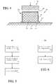
- FIG. 1depicts a perspective view of an electro-mechanical contact that is useful for understanding the present invention
- FIG. 2depicts an enlarged cross-section view of the electro-mechanical contact of FIG. 1 , taken along section line 2 - 2 ;
- FIG. 3depicts an enlarged cross-section view of another arrangement of the electro-mechanical contact of FIG. 1 , taken along section line 2 - 2 ;
- FIG. 4depicts an enlarged cross-section view of another arrangement of the electro-mechanical contact of FIG. 1 , taken along section line 2 - 2 ;
- FIG. 5is a flowchart that is useful for understanding the present invention.
- FIG. 6is another flowchart that is useful for understanding the present invention.
- FIG. 1depicts a perspective view of an electro-mechanical contact (hereinafter “contact”) 100 that is useful for understanding the present invention.
- the contact 100can be both magnetic and electrically conductive.
- the contact 100can magnetically attract an object while simultaneously providing electrical continuity to the object.
- Use of the contact 100 in an electronic devicecan eliminate the need to carefully align mating connectors of the prior art and reduce reliance on mechanical fasteners, thereby simplify the device's manufacturing process.
- the contact 100can be implemented without the use of a spring, which over time may lose its resilience and degrade in performance.
- the contact 100can comprise an electrically conductive magnetic member 102 and an electrically conductive jacket 104 .
- the magnetic member 102can protrude through an aperture 106 and into a cavity 108 defined in the jacket 104 .
- One or more guide members 110can protrude into the cavity 108 and contact the magnetic member 102 .
- the guide members 110can maintain alignment of the magnetic member 102 .
- the guide members 110can provide electrical conductivity between the magnetic member and the jacket 104 , although it should be noted that non-conductive guide members can be used and the invention is not limited in this regard.
- the guide members 110can be punched from one or more surfaces 114 , 116 of the jacket 104 .
- the magnetic member 102can comprise a magnet.
- the magnetcan comprise, for example, iron, hematite, magnetite or neodymium, or a combination of materials, such as neodymium, iron and boron. Still, wide varieties of other suitable magnetic materials are known in the art and the invention is not limited in this regard.
- the jacket 104can be formed from a material that is suitably rigid and suitably conductive, or can be formed from a plurality of materials that, when combined, provide suitable rigidity and conductivity.
- the jacket 104can be formed from a conductive metal, for example, aluminum, nickel, copper, silver, gold, etc.
- the jacket 104can be formed from an alloy, for example, steel, brass, nickel-silver, and so on.
- the jacket 104can be formed from a plurality of suitable materials, for example a substrate on which a veneer or plating is applied.
- the jacket 104can be formed of plastic which has a layer of conductive plating. Still, a myriad of other materials can be used to form the jacket 104 and the invention is not limited in this regard.
- the jacket 104can have generally square or rectangular surfaces 112 , 114 , 116 .
- the jacket 104can have other geometries.
- the jacket 104can be formed to be generally cylindrical in shape.
- the top side 112can be generally round, triangular, pentagonal, hexagonal, etc.
- the jacket 104can include a flange 118 .
- the flangecan be used to attach the contact 100 to a device component, such as a circuit board.
- the flange 118can be soldered or clamped to the device component.
- one or more apertures(not shown) can be defined in the flange 118 to facilitate use of fasteners to attach the contact 100 to the device component.
- the jacket 104can be formed in any suitable manner.
- the jacket 104can be molded, drawn, extruded, punched, or fabricated using any other suitable process.
- platingfor example electro-tin plating or nickel plating, can be applied to the jacket 104 .
- FIG. 2depicts an enlarged cross-section view of the contact 100 of FIG. 1 taken along section line 2 - 2 .
- the magnetic member 102can comprise a magnet 202 .
- a first portion 204 of the magnet 202can be positioned within the aperture 106 .
- the guide members 110 of the jacket 104can engage the first portion 204 and can provide electrical conductivity between the jacket 104 and the magnetic member 102 .
- the rim 206 of the aperture 106 and the guide members 110can maintain alignment of the magnetic member 102 .
- the magnetic member 102also can include a flange 208 .
- the flange 208can comprise a second portion of the magnetic member 102 .
- the magnetic member 102can move translationally between a first position in which a bottom 210 of the magnetic member 102 engages an object, such as an upper surface 212 of a circuit board 214 , and a second position in which the flange 208 engages the guide members 110 of the jacket 104 . In the first position, the flange 208 may not engage the guide members 110 .
- the magnetic member 102can comprise a conductive material or an electrically conductive plating adhered to the magnet 202 . Accordingly, the magnetic member 102 can be electrically continuous with the rim 206 of the aperture 106 and/or with the guide members 110 .
- the jacket 104can be attached to the circuit board 214 to form an electrically continuous connection with at least one circuit trace 216 of the circuit board 214 .
- the flange 118 of the jacket 104can engage the circuit trace 216 in a suitable manner.
- the flange 118can be soldered to the circuit trace 216 , attached to the circuit board 214 with a clamp or fastener, or held in electrical contact with the circuit trace 216 in any other suitable manner.
- the magnetic member 102can magnetically attract a second electrical contact (hereinafter “second contact”) 218 .
- second contacta second electrical contact
- the magnetic member 102can attract a portion 220 of the second contact 218 , which may comprise a ferromagnetic material, such that an electrically conductive surface 222 of the second contact 218 engages an upper surface 224 of the magnetic member 102 .
- an electrically continuous connectioncan be provided between the second contact 218 , the magnetic member 102 , the jacket 104 and the circuit trace 216 .
- FIG. 3depicts an enlarged cross-section view of another arrangement of the contact 100 of FIG. 1 taken along section line 2 - 2 .
- the magnet 202can be positioned within a sleeve 302 , which may be electrically conductive.
- the sleeve 302can be formed from a conductive metal or alloy, and/or have a conductive plating applied to its surface.
- the sleeve 302can be molded, drawn, extruded, punched, or fabricated using any other suitable process.
- the shape of the sleeve 302can be configured to receive the magnet 202 .
- the sleeve 302can have a cylindrical shape.
- the sleeve 302can be cubical in shape.
- the sleeve and magnetcan have any other shape and the invention is not so limited.
- the sleeve 302can have a shape that is different from the shape of the magnet 202 .
- the sleeve 302can be provided with an upper portion 304 .
- the sleeve 302can be generally tubular without the upper portion 304 .
- a portion 306 of the sleeve 302can be configured to form a flange 308 .
- an opening of the sleeve 302can be flared.
- the magnet 202can be statically positioned within the sleeve 302 using an interference fit, an adhesive, magnetic attraction or in any other suitable manner.
- the term “statically positioned”means that once assembled the magnet 202 and the sleeve 302 generally do not move relative to one another.
- the magnetic assembly 102can be positioned within the jacket 104 such that the guide members 110 engage the sleeve 302 so as to provide an electrically continuous connection. Further, the magnetic member 102 can move translationally between a first position in which a bottom 210 of the magnetic member 102 engages an object, such as the upper surface 212 of the circuit board 214 , and a second position in which the flange 308 of the sleeve 302 engages the guide members 110 of the jacket 104 . In one arrangement, while in the first position the flange 308 does not engage the guide members 110 , although the guide members 110 may still contact other portions of the sleeve 302 . As noted, in operation the magnetic member 102 can magnetically attract the second contact 218 . Thus, an electrically continuous connection can be provided between the second contact 218 , the sleeve 302 of the magnetic member 102 , the jacket 104 and the circuit trace 216 .
- FIG. 4depicts an enlarged cross-section view of another arrangement of the contact 100 of FIG. 1 taken along section line 2 - 2 .
- the jacketis not provided.
- the sleeve 302 of the magnetic member 102can extend to, and engage, the upper surface 212 of the circuit board 214 .
- the flange 308 of the sleeve 302can be statically positioned to engage the circuit trace 216 in a suitable manner.
- the flange 308can be soldered to the circuit trace 216 , attached to the circuit board 214 with a clamp or fastener, or held in electrical contact with the circuit trace 216 in any other suitable manner.
- the sleeve 302can be configured to include or not include the upper portion 304 .
- the magnetic member 102can magnetically attract the second contact 218 .
- an electrically continuous connectioncan be provided between the second contact 218 , the sleeve 302 , and the circuit trace 216 .
- FIG. 5is a flowchart that is useful for understanding a method 500 of assembling the contact onto a circuit board.
- the magnetcan be fitted into the sleeve to form the magnetic assembly.
- the magnetcan be interference fitted into the sleeve, held within the sleeve via magnetic attraction, or attached to the sleeve with an adhesive.
- the magnetic assemblycan be slideably fitted into the jacket.
- the jacketcan be attached to the circuit board.
- the jacketcan be soldered to the circuit board or attached with a clamp or fastener.
- FIG. 6is another flowchart that is useful for understanding a method 600 of assembling the contact onto a circuit board.
- the magnetcan be fitted into the sleeve to form the magnetic assembly.
- the sleevecan be attached to the circuit board. As noted, the sleeve can be soldered to the circuit board or attached with a clamp or fastener.
Landscapes
- Coupling Device And Connection With Printed Circuit (AREA)
Abstract
Description
Claims (20)
Priority Applications (1)
| Application Number | Priority Date | Filing Date | Title |
|---|---|---|---|
| US11/686,480US7416414B2 (en) | 2006-11-30 | 2007-03-15 | Magnetic member for providing electrical continuity and method for assembling same |
Applications Claiming Priority (2)
| Application Number | Priority Date | Filing Date | Title |
|---|---|---|---|
| US86800906P | 2006-11-30 | 2006-11-30 | |
| US11/686,480US7416414B2 (en) | 2006-11-30 | 2007-03-15 | Magnetic member for providing electrical continuity and method for assembling same |
Publications (2)
| Publication Number | Publication Date |
|---|---|
| US20080132090A1 US20080132090A1 (en) | 2008-06-05 |
| US7416414B2true US7416414B2 (en) | 2008-08-26 |
Family
ID=39476359
Family Applications (1)
| Application Number | Title | Priority Date | Filing Date |
|---|---|---|---|
| US11/686,480Expired - Fee RelatedUS7416414B2 (en) | 2006-11-30 | 2007-03-15 | Magnetic member for providing electrical continuity and method for assembling same |
Country Status (1)
| Country | Link |
|---|---|
| US (1) | US7416414B2 (en) |
Cited By (27)
| Publication number | Priority date | Publication date | Assignee | Title |
|---|---|---|---|---|
| US20100197148A1 (en)* | 2009-02-02 | 2010-08-05 | Apex Technologies, Inc. | Flexible magnetic interconnects |
| US20130263625A1 (en)* | 2012-03-19 | 2013-10-10 | Mary Catherine Taylor-Cattapan | Magnetically interchangeable jewelry and accessories |
| US8947185B2 (en) | 2010-07-12 | 2015-02-03 | Correlated Magnetics Research, Llc | Magnetic system |
| US8957751B2 (en) | 2010-12-10 | 2015-02-17 | Correlated Magnetics Research LLC | System and method for affecting flux of multi-pole magnetic structures |
| US8963668B2 (en) | 2008-04-04 | 2015-02-24 | Correlated Magnetics Research LLC | Field emission system and method |
| US9082539B2 (en) | 2008-04-04 | 2015-07-14 | Correlated Magnetics Research LLC. | System and method for producing magnetic structures |
| US9105380B2 (en) | 2008-04-04 | 2015-08-11 | Correlated Magnetics Research, Llc. | Magnetic attachment system |
| US9105384B2 (en) | 2008-04-04 | 2015-08-11 | Correlated Megnetics Research, Llc. | Apparatus and method for printing maxels |
| US9111673B2 (en) | 2010-05-10 | 2015-08-18 | Correlated Magnetics Research, Llc. | System and method for moving an object |
| US9202616B2 (en) | 2009-06-02 | 2015-12-01 | Correlated Magnetics Research, Llc | Intelligent magnetic system |
| US9202615B2 (en) | 2012-02-28 | 2015-12-01 | Correlated Magnetics Research, Llc | System for detaching a magnetic structure from a ferromagnetic material |
| US9219403B2 (en) | 2011-09-06 | 2015-12-22 | Correlated Magnetics Research, Llc | Magnetic shear force transfer device |
| US9245677B2 (en) | 2012-08-06 | 2016-01-26 | Correlated Magnetics Research, Llc. | System for concentrating and controlling magnetic flux of a multi-pole magnetic structure |
| US9257219B2 (en) | 2012-08-06 | 2016-02-09 | Correlated Magnetics Research, Llc. | System and method for magnetization |
| US9275783B2 (en) | 2012-10-15 | 2016-03-01 | Correlated Magnetics Research, Llc. | System and method for demagnetization of a magnetic structure region |
| US9298281B2 (en) | 2012-12-27 | 2016-03-29 | Correlated Magnetics Research, Llc. | Magnetic vector sensor positioning and communications system |
| US9312634B2 (en) | 2011-03-24 | 2016-04-12 | Correlated Magnetics Research LLC | Electrical adapter system |
| US9367783B2 (en) | 2009-06-02 | 2016-06-14 | Correlated Magnetics Research, Llc | Magnetizing printer and method for re-magnetizing at least a portion of a previously magnetized magnet |
| US9371923B2 (en) | 2008-04-04 | 2016-06-21 | Correlated Magnetics Research, Llc | Magnetic valve assembly |
| US9404776B2 (en) | 2009-06-02 | 2016-08-02 | Correlated Magnetics Research, Llc. | System and method for tailoring polarity transitions of magnetic structures |
| US9559456B2 (en) | 2013-03-15 | 2017-01-31 | Google Technology Holdings LLC | Magnetic electrical connection system for an electronic device |
| CN106558784A (en)* | 2015-09-30 | 2017-04-05 | 苹果公司 | Magnetic surface contact |
| US9711268B2 (en) | 2009-09-22 | 2017-07-18 | Correlated Magnetics Research, Llc | System and method for tailoring magnetic forces |
| US10283952B2 (en) | 2017-06-22 | 2019-05-07 | Bretford Manufacturing, Inc. | Rapidly deployable floor power system |
| US20190190195A1 (en)* | 2017-12-20 | 2019-06-20 | North Inc. | Magnetic connector |
| USD955977S1 (en) | 2020-04-10 | 2022-06-28 | Water Pik, Inc. | Charging connector |
| US11495912B2 (en) | 2020-04-10 | 2022-11-08 | Water Pik, Inc. | Charging connector for oral health devices |
Families Citing this family (5)
| Publication number | Priority date | Publication date | Assignee | Title |
|---|---|---|---|---|
| JP6198018B2 (en)* | 2015-02-19 | 2017-09-20 | Smk株式会社 | Magnetic bonding type connector |
| EP3104671B1 (en)* | 2015-05-08 | 2018-07-18 | Joylabz LLC | Methods and systems for magnetic coupling |
| US9705242B1 (en) | 2015-12-18 | 2017-07-11 | Microsoft Technology Licensing, Llc | Electrical connector |
| DE102020114650B3 (en)* | 2020-06-02 | 2021-06-02 | Semikron Elektronik Gmbh & Co. Kg | Power electronic assembly with an electrically conductive sleeve and with a circuit carrier |
| TWI771073B (en)* | 2021-06-21 | 2022-07-11 | 洪松齡 | Cabinet with AED light display |
Citations (11)
| Publication number | Priority date | Publication date | Assignee | Title |
|---|---|---|---|---|
| US4611050A (en) | 1983-04-04 | 1986-09-09 | Phelps Dodge Industries, Inc. | Essentially linear polymer having a plurality of amide, imide and ester groups therein, and a method of making the same |
| US4659622A (en) | 1983-04-04 | 1987-04-21 | Phelps Dodge Industries, Inc. | Essentially linear polymer having a plurality of amide, imide and ester groups therein, a tinnable and solderable magnet wire, and a method of making the same |
| US6110399A (en) | 1994-01-27 | 2000-08-29 | Loctite (Ireland) Limited | Compositions and method for providing anisotropic conductive pathways and bonds between two sets of conductors |
| US6129559A (en) | 1996-01-19 | 2000-10-10 | Sumitomo Electric Industries, Ltd. | Microconnector and method of manufacturing the same |
| US6401330B2 (en) | 1993-04-13 | 2002-06-11 | Micron Technology, Inc. | Apparatus for mounting an integrated circuit onto a printed circuit board and then testing the integrated circuit |
| US20020164892A1 (en)* | 2001-04-26 | 2002-11-07 | Coilcraft, Incorporated | Surface mountable electronic component |
| US6561815B1 (en) | 1999-07-02 | 2003-05-13 | Siegfried Schmidt | Electromechanical connecting device |
| US6796840B2 (en)* | 2002-02-14 | 2004-09-28 | Alps Electric Co., Ltd. | Surface mounting type non-reversible circuit element having superior productivity |
| US7074045B2 (en)* | 2003-07-22 | 2006-07-11 | Fujitsu Limited | Portable terminal device and open/close detector |
| US20070207672A1 (en)* | 2006-02-28 | 2007-09-06 | Sanyo Seimitsu Co., Ltd. | Reciprocal vibration generator |
| US7341458B1 (en)* | 2007-03-28 | 2008-03-11 | Chao Ming Koh | Electrical signal transmission connector assembly with magnetically connected receptacle and plug |
- 2007
- 2007-03-15USUS11/686,480patent/US7416414B2/ennot_activeExpired - Fee Related
Patent Citations (11)
| Publication number | Priority date | Publication date | Assignee | Title |
|---|---|---|---|---|
| US4611050A (en) | 1983-04-04 | 1986-09-09 | Phelps Dodge Industries, Inc. | Essentially linear polymer having a plurality of amide, imide and ester groups therein, and a method of making the same |
| US4659622A (en) | 1983-04-04 | 1987-04-21 | Phelps Dodge Industries, Inc. | Essentially linear polymer having a plurality of amide, imide and ester groups therein, a tinnable and solderable magnet wire, and a method of making the same |
| US6401330B2 (en) | 1993-04-13 | 2002-06-11 | Micron Technology, Inc. | Apparatus for mounting an integrated circuit onto a printed circuit board and then testing the integrated circuit |
| US6110399A (en) | 1994-01-27 | 2000-08-29 | Loctite (Ireland) Limited | Compositions and method for providing anisotropic conductive pathways and bonds between two sets of conductors |
| US6129559A (en) | 1996-01-19 | 2000-10-10 | Sumitomo Electric Industries, Ltd. | Microconnector and method of manufacturing the same |
| US6561815B1 (en) | 1999-07-02 | 2003-05-13 | Siegfried Schmidt | Electromechanical connecting device |
| US20020164892A1 (en)* | 2001-04-26 | 2002-11-07 | Coilcraft, Incorporated | Surface mountable electronic component |
| US6796840B2 (en)* | 2002-02-14 | 2004-09-28 | Alps Electric Co., Ltd. | Surface mounting type non-reversible circuit element having superior productivity |
| US7074045B2 (en)* | 2003-07-22 | 2006-07-11 | Fujitsu Limited | Portable terminal device and open/close detector |
| US20070207672A1 (en)* | 2006-02-28 | 2007-09-06 | Sanyo Seimitsu Co., Ltd. | Reciprocal vibration generator |
| US7341458B1 (en)* | 2007-03-28 | 2008-03-11 | Chao Ming Koh | Electrical signal transmission connector assembly with magnetically connected receptacle and plug |
Non-Patent Citations (2)
| Title |
|---|
| Ferrite Magnets (product descriptions), http://www.shawmagnets.com/ferritemagnets.html, Accessed Jan. 29, 2007, 2 pgs. |
| U.S. Appl. No. 11/305,780, filed Dec. 16, 2005, Hernandez, et al., 19 pgs. |
Cited By (34)
| Publication number | Priority date | Publication date | Assignee | Title |
|---|---|---|---|---|
| US9269482B2 (en) | 2008-04-04 | 2016-02-23 | Correlated Magnetics Research, Llc. | Magnetizing apparatus |
| US9105380B2 (en) | 2008-04-04 | 2015-08-11 | Correlated Magnetics Research, Llc. | Magnetic attachment system |
| US9371923B2 (en) | 2008-04-04 | 2016-06-21 | Correlated Magnetics Research, Llc | Magnetic valve assembly |
| US9536650B2 (en) | 2008-04-04 | 2017-01-03 | Correlated Magnetics Research, Llc. | Magnetic structure |
| US9105384B2 (en) | 2008-04-04 | 2015-08-11 | Correlated Megnetics Research, Llc. | Apparatus and method for printing maxels |
| US8963668B2 (en) | 2008-04-04 | 2015-02-24 | Correlated Magnetics Research LLC | Field emission system and method |
| US9082539B2 (en) | 2008-04-04 | 2015-07-14 | Correlated Magnetics Research LLC. | System and method for producing magnetic structures |
| US8187006B2 (en) | 2009-02-02 | 2012-05-29 | Apex Technologies, Inc | Flexible magnetic interconnects |
| US20100197148A1 (en)* | 2009-02-02 | 2010-08-05 | Apex Technologies, Inc. | Flexible magnetic interconnects |
| US9404776B2 (en) | 2009-06-02 | 2016-08-02 | Correlated Magnetics Research, Llc. | System and method for tailoring polarity transitions of magnetic structures |
| US9202616B2 (en) | 2009-06-02 | 2015-12-01 | Correlated Magnetics Research, Llc | Intelligent magnetic system |
| US9367783B2 (en) | 2009-06-02 | 2016-06-14 | Correlated Magnetics Research, Llc | Magnetizing printer and method for re-magnetizing at least a portion of a previously magnetized magnet |
| US9711268B2 (en) | 2009-09-22 | 2017-07-18 | Correlated Magnetics Research, Llc | System and method for tailoring magnetic forces |
| US9406424B2 (en) | 2010-05-10 | 2016-08-02 | Correlated Magnetics Research, Llc | System and method for moving an object |
| US9111673B2 (en) | 2010-05-10 | 2015-08-18 | Correlated Magnetics Research, Llc. | System and method for moving an object |
| US8947185B2 (en) | 2010-07-12 | 2015-02-03 | Correlated Magnetics Research, Llc | Magnetic system |
| US9111672B2 (en) | 2010-07-12 | 2015-08-18 | Correlated Magnetics Research LLC. | Multilevel correlated magnetic system |
| US8957751B2 (en) | 2010-12-10 | 2015-02-17 | Correlated Magnetics Research LLC | System and method for affecting flux of multi-pole magnetic structures |
| US9312634B2 (en) | 2011-03-24 | 2016-04-12 | Correlated Magnetics Research LLC | Electrical adapter system |
| US9219403B2 (en) | 2011-09-06 | 2015-12-22 | Correlated Magnetics Research, Llc | Magnetic shear force transfer device |
| US9202615B2 (en) | 2012-02-28 | 2015-12-01 | Correlated Magnetics Research, Llc | System for detaching a magnetic structure from a ferromagnetic material |
| US20130263625A1 (en)* | 2012-03-19 | 2013-10-10 | Mary Catherine Taylor-Cattapan | Magnetically interchangeable jewelry and accessories |
| US9257219B2 (en) | 2012-08-06 | 2016-02-09 | Correlated Magnetics Research, Llc. | System and method for magnetization |
| US9245677B2 (en) | 2012-08-06 | 2016-01-26 | Correlated Magnetics Research, Llc. | System for concentrating and controlling magnetic flux of a multi-pole magnetic structure |
| US9275783B2 (en) | 2012-10-15 | 2016-03-01 | Correlated Magnetics Research, Llc. | System and method for demagnetization of a magnetic structure region |
| US9588599B2 (en) | 2012-12-27 | 2017-03-07 | Correlated Magnetics Research, Llc. | Magnetic vector sensor positioning and communication system |
| US9298281B2 (en) | 2012-12-27 | 2016-03-29 | Correlated Magnetics Research, Llc. | Magnetic vector sensor positioning and communications system |
| US9559456B2 (en) | 2013-03-15 | 2017-01-31 | Google Technology Holdings LLC | Magnetic electrical connection system for an electronic device |
| CN106558784A (en)* | 2015-09-30 | 2017-04-05 | 苹果公司 | Magnetic surface contact |
| US10283952B2 (en) | 2017-06-22 | 2019-05-07 | Bretford Manufacturing, Inc. | Rapidly deployable floor power system |
| US20190190195A1 (en)* | 2017-12-20 | 2019-06-20 | North Inc. | Magnetic connector |
| US10468838B2 (en)* | 2017-12-20 | 2019-11-05 | North Inc. | Magnetic connector |
| USD955977S1 (en) | 2020-04-10 | 2022-06-28 | Water Pik, Inc. | Charging connector |
| US11495912B2 (en) | 2020-04-10 | 2022-11-08 | Water Pik, Inc. | Charging connector for oral health devices |
Also Published As
| Publication number | Publication date |
|---|---|
| US20080132090A1 (en) | 2008-06-05 |
Similar Documents
| Publication | Publication Date | Title |
|---|---|---|
| US7416414B2 (en) | Magnetic member for providing electrical continuity and method for assembling same | |
| US8885355B2 (en) | Device having snaps with soldered snap members | |
| JP6004520B2 (en) | Electrical connector | |
| KR101868929B1 (en) | Low-profile spring-loaded contacts | |
| JP5472272B2 (en) | Coaxial connector plug and manufacturing method thereof | |
| US20160344118A1 (en) | Separable Electrical Connector and Method of Making It | |
| US20120317801A1 (en) | Reusable electronic circuit assembling and testing system and uses thereof | |
| TW201917954A (en) | Electrical connector and the method of making the same | |
| JPH07235348A (en) | Electric connector assembly with filter of multi-terminal | |
| JP2005110200A (en) | Film antenna device | |
| JP2005057495A (en) | Electroacoustic transducer and connection element structure used therefor | |
| JP4532234B2 (en) | connector | |
| JP2010272244A (en) | Coaxial electrical connector | |
| KR102183030B1 (en) | Mounting structure on metal case for electric contact terminal | |
| US5481618A (en) | Interconnection of a speaker using magnetic coupling | |
| US6940459B2 (en) | Antenna assembly with electrical connectors | |
| US20150207250A1 (en) | Printed circuit board device | |
| US7601016B2 (en) | Connector substrate and speaker input terminal connection structure | |
| JP6751867B2 (en) | Conductive connection structure of elastic connector and elastic connector | |
| JP6198018B2 (en) | Magnetic bonding type connector | |
| JPH11176501A (en) | Manufacture of electric device using flat flexible substrate | |
| EP4586410A1 (en) | Electrical terminal for an electronic device | |
| JP2015090792A (en) | Connector connection structure and assembling method thereof | |
| JP2018078078A (en) | Connector and electronic component with connector | |
| TW554581B (en) | Method of making an electrical connector |
Legal Events
| Date | Code | Title | Description |
|---|---|---|---|
| AS | Assignment | Owner name:MOTOROLA, INC., ILLINOIS Free format text:ASSIGNMENT OF ASSIGNORS INTEREST;ASSIGNORS:BOZZONE, STEPHEN O.;HAMPTON, PATRICK;KASSOF, EVAN J.;AND OTHERS;REEL/FRAME:019016/0092;SIGNING DATES FROM 20070206 TO 20070208 | |
| STCF | Information on status: patent grant | Free format text:PATENTED CASE | |
| AS | Assignment | Owner name:MOTOROLA MOBILITY, INC, ILLINOIS Free format text:ASSIGNMENT OF ASSIGNORS INTEREST;ASSIGNOR:MOTOROLA, INC;REEL/FRAME:025673/0558 Effective date:20100731 | |
| FPAY | Fee payment | Year of fee payment:4 | |
| AS | Assignment | Owner name:MOTOROLA MOBILITY LLC, ILLINOIS Free format text:CHANGE OF NAME;ASSIGNOR:MOTOROLA MOBILITY, INC.;REEL/FRAME:029216/0282 Effective date:20120622 | |
| AS | Assignment | Owner name:GOOGLE TECHNOLOGY HOLDINGS LLC, CALIFORNIA Free format text:ASSIGNMENT OF ASSIGNORS INTEREST;ASSIGNOR:MOTOROLA MOBILITY LLC;REEL/FRAME:034451/0001 Effective date:20141028 | |
| FPAY | Fee payment | Year of fee payment:8 | |
| FEPP | Fee payment procedure | Free format text:MAINTENANCE FEE REMINDER MAILED (ORIGINAL EVENT CODE: REM.); ENTITY STATUS OF PATENT OWNER: LARGE ENTITY | |
| LAPS | Lapse for failure to pay maintenance fees | Free format text:PATENT EXPIRED FOR FAILURE TO PAY MAINTENANCE FEES (ORIGINAL EVENT CODE: EXP.); ENTITY STATUS OF PATENT OWNER: LARGE ENTITY | |
| STCH | Information on status: patent discontinuation | Free format text:PATENT EXPIRED DUE TO NONPAYMENT OF MAINTENANCE FEES UNDER 37 CFR 1.362 | |
| FP | Lapsed due to failure to pay maintenance fee | Effective date:20200826 |