US7415310B2 - System for home automation - Google Patents
System for home automationDownload PDFInfo
- Publication number
- US7415310B2 US7415310B2US11/227,988US22798805AUS7415310B2US 7415310 B2US7415310 B2US 7415310B2US 22798805 AUS22798805 AUS 22798805AUS 7415310 B2US7415310 B2US 7415310B2
- Authority
- US
- United States
- Prior art keywords
- server
- network
- scene
- slave device
- controller
- Prior art date
- Legal status (The legal status is an assumption and is not a legal conclusion. Google has not performed a legal analysis and makes no representation as to the accuracy of the status listed.)
- Expired - Fee Related
Links
Images


Classifications
- H—ELECTRICITY
- H04—ELECTRIC COMMUNICATION TECHNIQUE
- H04L—TRANSMISSION OF DIGITAL INFORMATION, e.g. TELEGRAPHIC COMMUNICATION
- H04L12/00—Data switching networks
- H04L12/28—Data switching networks characterised by path configuration, e.g. LAN [Local Area Networks] or WAN [Wide Area Networks]
- H04L12/2803—Home automation networks
- H04L12/2823—Reporting information sensed by appliance or service execution status of appliance services in a home automation network
- H—ELECTRICITY
- H04—ELECTRIC COMMUNICATION TECHNIQUE
- H04L—TRANSMISSION OF DIGITAL INFORMATION, e.g. TELEGRAPHIC COMMUNICATION
- H04L12/00—Data switching networks
- H04L12/28—Data switching networks characterised by path configuration, e.g. LAN [Local Area Networks] or WAN [Wide Area Networks]
- H04L12/2803—Home automation networks
- H04L12/2816—Controlling appliance services of a home automation network by calling their functionalities
- H04L12/282—Controlling appliance services of a home automation network by calling their functionalities based on user interaction within the home
- H—ELECTRICITY
- H04—ELECTRIC COMMUNICATION TECHNIQUE
- H04L—TRANSMISSION OF DIGITAL INFORMATION, e.g. TELEGRAPHIC COMMUNICATION
- H04L12/00—Data switching networks
- H04L12/28—Data switching networks characterised by path configuration, e.g. LAN [Local Area Networks] or WAN [Wide Area Networks]
- H04L12/2803—Home automation networks
- H04L12/283—Processing of data at an internetworking point of a home automation network
- H04L12/2836—Protocol conversion between an external network and a home network
- H—ELECTRICITY
- H04—ELECTRIC COMMUNICATION TECHNIQUE
- H04L—TRANSMISSION OF DIGITAL INFORMATION, e.g. TELEGRAPHIC COMMUNICATION
- H04L12/00—Data switching networks
- H04L12/28—Data switching networks characterised by path configuration, e.g. LAN [Local Area Networks] or WAN [Wide Area Networks]
- H04L12/2803—Home automation networks
- H04L2012/2847—Home automation networks characterised by the type of home appliance used
- H04L2012/285—Generic home appliances, e.g. refrigerators
Definitions
- the inventiongenerally relates to a home automation system, and more specifically to a system for operating, maintaining, and configuring a home automation network using a home automation protocol.
- appliancesmay contain significant programmable and network-ready circuitry and interfaces. These appliances may be connected to a home network for use in setting home environment scenes. These scenes may include scenes such as varieties of lighting, temperature, or sound.
- Protocolsare used for interfacing home environment appliances with a network.
- Several commercially available network systemsuse proprietary protocols to interface devices with user interfaces to control the devices.
- Such interfaces and networkstypically work with a single protocol and exclude devices that do not operate with the same proprietary protocol.
- such networksmay not be convenient for adding devices, controlling and changing scenes adaptively, or interacting with the network in a user-friendly manner.
- a home automation systemfor controlling home environment appliances.
- the systemincludes a network to connect a number of controllers, slave devices with associated appliances, servers for maintaining databases of home automation network protocols.
- Controllersare in communication with the network and may include an indicator.
- Slave devicesmay take on a number of operational states associated with scene information during operation.
- the serversmay be scene servers, which contain information about all the scene settings in the network, or status servers, which contain information about all the operational states of devices in the network.
- the scene server and status servermay be separate units provided in the system, and are in communication with each other.
- the networkis adapted to route signals and commands between and to the slave devices, controllers, and servers in the network.
- FIG. 1illustrates a schematic view of a home with devices connected to a home automation network.
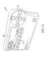
- FIG. 2Aillustrates a controller example
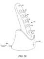
- FIG. 2Billustrates another controller and a base.
- FIG. 2Cillustrates a passive infrared activated controller.
- FIG. 2Dillustrates a switch with an up/down/dimmer function.
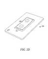
- FIG. 2Eillustrates a receptacle device
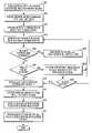
- FIG. 3is a flow chart describing communication with the home automation protocol.
- FIG. 4is a flow chart describing operations of the home automation protocol.
- FIG. 5is a flow chart describing the setting of a new scene in a home automation protocol.
- FIG. 6is a flow chart describing operation of the network with battery chargers.
- FIG. 1illustrates a home environment 100 which may include a number of electrical and electronic appliances, such as lights, controlled by a network of node devices or slave devices 101 and controllers 105 .
- the home environment 100may include a one or more distinct rooms 102 , 103 , though these rooms 102 , 103 may be joined or portioned as desired.
- the controllers 105may activate the slave devices 101 by communicating across the network from room to room.
- Slave devices 101 and controllers 105may be powered by battery devices such as standard alkaline battery cells, rechargeable battery cells like NiCd or Li-ion cells, or powered by connection to wall outlets.
- the networkis configured to route commands and signals between different controllers 105 and slave devices 101 in the network.
- Communicationincludes wireless, such as radio frequency (RF), microwave, infrared, or other wireless communication, and/or wired communications.
- the controllers 105are devices that may be in communication with the network, and may be activated and manipulated by buttons present on the controller 105 . A user can press the buttons on the controllers 105 to send commands to the slave devices 101 in the network to change a state of a component of the slave device 101 , such as a relay or triac.
- the controller 105may also be activated in other ways, such as by voice. Since the slave device 101 may supply power to the electrical or electronic appliance, a change in state of the component of the slave device 101 may in turn change the state of the electrical or electronic appliances.
- FIG. 2Aillustrates an example of a controller 105 , such as control module 201 .
- the control module 201may include a display 290 , such as liquid crystal display (LCD) screen, and input device 292 .
- the input device 292may include up, down, left, right and/or enter buttons, or other inputting devices, such as a keypad or a microphone for receiving voice-activated commands.
- a control menu with optionsmay be shown to the user on the display 290 .
- the useris able to navigate through each of the options to add, edit, or delete entries.
- the usermay be presented with a ‘My Home’ option which allows the user to add rooms and edit rooms in the network.
- the roomsinclude living rooms, dining rooms, halls, garages, bathrooms, bedrooms, dens and/or kitchens.
- Another optionmay include a ‘My Scene’ option that allows a user to add, edit and turn on and off scenes.
- a scenemay be a group of loads, such as lights or appliances, that turn on/off and/or dim up and down when a user pushes a button, or automatically when an event occurs.
- the scenesmay be programmed to one or more of channel buttons 294 . For example, activating scene one control all the lights and a television in a living room turn on. Scene two may have all the lights in the living room dim down, the television turn off and a stereo system turn on.
- Another option displayed to the usermay include a ‘My Event’ option.
- the usercan add or edit events by entering a name of the event, and configure the events by selecting with the input device 292 scenes that will be activated or deactivated when the event occurs.
- an eventmay be one that causes all lights and appliances in the kitchen turn off at 10:00 pm, and outside flood lights are turn on.
- a ‘Set Up’ optionfor entering settings such as month, day, year, and time, and other settings such as a longitude and/or latitude of the user.
- a ‘Main’ optionto send the user back to the main menu when selected.
- the main menumay display the user options and other indicators such as the current time.
- FIG. 2B-2Cillustrates other controllers that may be used in the network.
- FIG. 2Billustrates a handheld controller 203 .
- the handheld controller 203may be placed in a base 204 .
- the base 204may be used for charging the controller 203 and also for containing a server processor, as described in more detail below.
- the base 204may include a power cord 205 for supplying power to the base 204 .
- the handheld controller 203may include controller buttons 213 , 214 , and 215 for activating different functions.
- types of buttonsmay include on/off/enter buttons 213 , scene control buttons 214 , and an all-on/all-off panic button 215 .
- the handheld controller 203may also include indicators 206 , such as light emitting diodes (LED's).
- LED'slight emitting diodes
- FIG. 2Cillustrates a passive infrared (PIR) controller 202 .
- the PIR controller 202sends a control signal to a slave device 101 upon detection of presence of body heat from a person.
- the PIR controller 202includes a lens 207 for cover a PIR sensor.
- Other examples of controllers 105include wall-mounted controllers, such as a wall mounted controller similarly configured to the hand held controller 203 , and a key fob controller.
- FIGS. 2D-2Eillustrate slave device 101 that may be controlled by the controllers 105 , 201 and 203 , or other controllers.
- FIG. 2Dillustrates a wall dimmer switch 208 .
- the wall dimmer switch 208may receive commands from the controllers 101 , 201 , 203 to turn loads, such as lights, on or off, and/or to dim the loads up or down. To achieve such changes in the loads, the commands may cause the wall dimmer switch 208 to change the state of a relay or semiconductor device, such as a triac, positioned in the wall dimmer switch 208 .
- a relay or semiconductor devicesuch as a triac
- the wall dimmer switch 208may include a toggle switch 230 that may be pressed by a user to turn loads on and off, and/or dim the loads up and down without having to use the controller 105 , 201 , 203 or other controllers.
- the wall dimmer switch 208may also include a gap switch 230 that, when set in an open position, physically decouples a flow of current from a power source to the wall dimmer switch 208 .
- FIG. 2Eillustrates an example of a receptacle device 230 .
- the receptacle device 230may be inserted into a wall as a power outlet to control power to loads or electrical appliances that are plugged into the receptacle device 230 .
- the receptacle device 230may include a switch, such as a relay or triac, to control power to a load or appliance that is plugged in to the receptacle device 230 .
- the receptacle device 230may include indictors 233 , such as LED's.
- Other slave devices 101may also be used such as a wall receptacle converter that may be plugged into a standard receptacle and include a receptacle for a power cord of the device or appliance to plug into.
- Other slave devices 101include an outdoor module that has a housing to protect the module from the elements. The outdoor module may include a relay type plug and a prong receptacle to control the on and off switching of loads for outdoor devices.
- Other slave modules 101include a lamp socket module with a mechanical relay-type screw-in module utilizing RF signals to communicate commands from a controller 105 , 201 , 203 to control the on and off switching of loads for incandescent lamps and an outdoor flood lamp module.
- Slave devices 101may interface with the network using different protocols. Some slave devices 101 may run a first protocol, while other slave devices may run protocols other than the first protocol.
- the home appliance network of the applicationmay allow slave devices 101 that operate different protocols to work with the network.
- the networkmay also include a number of servers, such as a status server 115 and a scene server 120 , which are connected to the network.
- the status server 115 and the scene server 120may store different databases of information concerning different aspects of the slave devices 101 and controllers 105 , as well as information concerning operational states of the devices.
- the operational states of the slave devicesmay be known as “scenes,” where a scene may be a combination of operational states of the slave devices 101 .
- the slave devices 101control appliances, which may be in an on/off state, or varying along some scale of actuation or operation, depending on the type of appliance controlled by its associated slave device.
- the status server 115 and the scene server 120may be implemented as separate processors or servers, in distinct housings, or together in the same housing.
- the status server 115 and the scene server 120may be implemented at one or more locations within the network, such as in the base 204 of the handheld controller 203 .
- the status server 115may store in one location information about each node, such as controller 105 and slave device 101 , in the system.
- the status server 115 functionalitymay be transferred between the one or more possible status servers 115 , so that there can be a main status server and auxiliary status servers.
- the controller 105may also assume the functionality of a status server 115 .
- the status server 115 functionalitymay be stored as logic in a memory.
- the logic illustrated in the sequence of FIGS. 3-6may be encoded in a signal bearing medium, a computer readable medium such as a memory, programmed within a device such as one or more integrated circuits, or processed by a controller or a computer.
- the softwaremay reside in a memory resident to or interfaced to the network slave devices 101 , servers, a communication interface, or any other type of non-volatile or volatile memory interfaced or resident to the network logic.
- the memorymay include an ordered listing of executable instructions for implementing logical functions.
- a logical functionmay be implemented through digital circuitry, through source code, through analog circuitry, or through an analog source such through an analog electrical, audio, or video signal.
- the softwaremay be embodied in any computer-readable or signal-bearing medium, for use by, or in connection with an instruction executable system, apparatus, or device.
- Such a systemmay include a computer-based system, a processor-containing system, or another system that may selectively fetch instructions from an instruction executable system, apparatus, or device that may also execute instructions.
- a “computer-readable medium,” “machine-readable medium,” “propagated-signal” medium, and/or “signal-bearing medium”may include any means that contains, stores, communicates, propagates, or transports software for use by or in connection with an instruction executable system, apparatus, or device.
- the machine-readable mediummay selectively be, but not limited to, an electronic, magnetic, optical, electromagnetic, infrared, or semiconductor system, apparatus, device, or propagation medium.
- a non-exhaustive list of examples of a machine-readable mediumwould include: an electrical connection “electronic” having one or more wires, a portable magnetic or optical disk, a volatile memory such as a Random Access Memory “RAM” (electronic), a Read-Only Memory “ROM” (electronic), an Erasable Programmable Read-Only Memory (EPROM or Flash memory) (electronic), or an optical fiber (optical).
- a machine-readable mediummay also include a tangible medium upon which software is printed, as the software may be electronically stored as an image or in another format (e.g., through an optical scan), then compiled, and/or interpreted or otherwise processed. The processed medium may be stored in a computer and/or machine memory.
- Status servers 115are connected to the network and in communication with slave devices 101 and controllers 105 .
- Status servers 115may be located in the network between slave devices 101 and controllers 105 , such that the slave device 101 communicates first with a status server 115 before the status server 115 communicates with a controller 105 .
- Devices that use the first protocolmay report their state whenever that state changes. This makes the status of devices available whether or not they are listening to the network.
- Devices that do not communicate with the first protocolmay be polled periodically by the Status Server 115 .
- the status server 115may be configured to not store any scene status information.
- the scene server 120may centralize the control of the scenes for a system.
- the scene server 120includes a database of scene settings for a home environment.
- scenesinclude the operational states of the slave devices 101 in the network controlling electrical and electronic appliances associated with the slave devices.
- a usercan change the state of the slave devices 101 so that the appliances combine together to change the settings of a room environment.
- Such settingmight include the lighting state of a room, temperature state, sound ambience, humidity, scent, or other possible environmental characteristics.
- the scene server 120may allow easy access to change the scenes with one or more buttons on a controller 105 . For example, pushing a button on a controller may cause lights in a hallway leading from a bedroom to a kitchen to turn on, lights in a kitchen to dim up, a coffee machine to turn on, and night lights to turn off.
- a controller 105may include a user interface unit 107 for a user to easily modify the scenes.
- the user interface unit 107may include a graphical user interface or a personal computer (PC).
- the scene server 120also may allow non-controllers to control scenes if non-controllers are present in the network.
- Such non-controllersmight be routing slaves 101 a , where the routing slave device 101 a maintains a list of routing instructions for the devices in the network and where the routing slave device 101 a sends one or more commands and one or more reports without receiving a command from a controller 105 .
- An example of a routing slave 101 ais the PIR module 202 , described above.
- the scene server 120 functionscan be transferred to other devices in the network.
- a scene server 120may have a scene server firmware level which is compared to the device firmware level of the slave device 101 when the slave device 101 is added to the network. If the device firmware level is more recent than the scene server firmware level, the new slave device 101 may become the new scene server 120 and other devices 101 on the network may be notified and updated accordingly.
- scene server 120 functions and status server 115 functionsmay be included in the same device 101 or controller 105 .
- scene servers 120may be connected to the network and in communication with controllers 105 and slave devices 101 that are also connected to the network.
- Scene servers 120may be located in the network between slave devices 101 and controllers 105 such that a slave device 101 may communicate with a scene server 120 first before the scene server 120 communicates with a controller 105 .
- a home automation systemmay also include battery chargers (see e.g. base 204 in FIG. 2B ), which charge up controllers 105 that are associated with a battery charger.
- the battery charger base 204may contain communications functionality, firmware, and or software for communication with the network and transferring data to a controller 105 . This allows controllers 105 to be movable and not required connection to a wall power unit or extension cord.
- a controller 105may be placed in a battery charger base 204 for charging and communicating with the base 204 .
- a controller 105When a controller 105 is in a base 204 , it may inform the status server 115 , so that any scene information may be routed through the base 204 . The controller 105 , then, does not need to communicate with the status server 115 wirelessly. This may be desirable when battery devices are unavailable for communication unless they communicate to the user where their location.
- the battery charger 108can be used to locate controllers 105 . When a charger 108 is powered up, it may send a signal to the status server 115 that then signals all controllers 105 not in a base 204 associated with the controller 105 to trigger an audible beep. A new controller 105 may be added to the network by coupling the controller 105 to its associated base 204 . It may occur that some controllers 105 are lost, in that they can no longer be located and have not checked in when polled in the network. Any lost controllers 105 may be automatically replaced and their scene information may be copied to the new controller 105 .
- FIG. 3depicts a method for communicating with slave devices 101 in the home automation network using the home automation network protocol.
- a usersends a signal 301 from a controller 105 , connected to a network of slave devices 101 , controllers 105 , status servers 115 , and scene servers 120 , to a scene server 120 when a button on the controller 105 is actuated by the user. This may be done when the user wishes to actuate an appliance circuit 111 associated with a slave device 101 .
- the usermay want to turn on a light, for example, though other actions include turning off a light, changing the light level, changing a thermostat setting, actuating a sensor, or interacting with a home PC or entertainment network.
- the scene server 120may receive the signal directly from the controller 105 in the network, or the signal may be routed through the network by a routing slave device 101 a , other slave devices 101 and/or controllers 105 .
- the scene server 120may process 302 the signal by searching a database including a list of the one or more slave devices 101 connected to the network.
- the scene server 120selects 303 a slave device 101 , based on the signal received from the controller 105 . Thereafter, the scene server 120 may send 304 a signal to the selected slave device 101 to change the state of the appliance circuit 111 associated with the selected slave device 101 .
- the slave device 101acknowledges 305 the signal from the scene server 120 , changes its operation state, and sends a signal to a status server 115 .
- the signalmay be sent directly to the status server 115 interconnected between the slave device 101 and the controller 105 , or the signal may be routed by a routing slave device 102 through the network.
- the signalmay include actual or assumed status of the connected devices 101 .
- the slave device 101may include circuitry that determines if a load of the device 101 actually changed state, such as a light bulb turning on, or not, or a light bulb missing or burned out.
- the assumed statusmay include a relay or triac of the slave device 101 switching, assuming that the load of the controlled device is operating properly.
- the status server 115may query a database contained in the status server 115 , where the database may include a list of operational states of the slave devices 101 in the network.
- the status server 115queries the database 306 to determine which, if any, status LED 203 on the controller 105 to turn on or turn off.
- the status LED's 203 on the controller 105may indicate the state of the slave device 101 , and its associated appliance circuit.
- the status server 115sends a signal 307 to the controller 105 to turn on or turn off the determined LED 203 , based on the results of the database query 306 .
- the appliance circuitmay be a relay, triac, or other semiconductor switching devices that are normally incorporated in home electrical and electronic appliances.
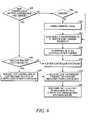
- FIG. 4depicts a method for automating and configuring a home automation network for a home environment.
- a network including one or more controllers 105 running a first protocolmay be provided.
- the networkmay also include a number of slave devices 101 running the first protocol, as well as a number of slave devices 101 running other protocols.
- the networkfurther may also include a number of status servers 115 or scene servers 120 in communication with the network.
- the status server 115may have a status server firmware level
- the scene server 120may have a scene server firmware level.
- the slave devices 101may allow a number of operational states, as well as a slave device status server firmware level and a slave device scene server firmware level.
- the home automation networkfunctions by storing, in a status server 115 , status information 401 associated with the operational state of a slave device 101 .
- the slave device 101which may run the first protocol, may send 402 status information indicating the operational state of the slave device 101 and the appliance circuit associated with the slave device 101 , to the status server 115 when the operational state of the slave device 101 changes.
- the networkperiodically polls 403 slave devices 101 running a second protocol to determine if the different protocol slave device 101 has changed its operational state.
- the networkmay compare 404 the slave device status server firmware revision level with the status server firmware revision level to determine if a newer version of status server firmware is available. If there is a newer version of status server firmware available, the network may determine 405 if a status server 115 already is present in the network. If there is an existing status server 115 , the network may move the status server functions 406 to the slave device 101 that is sending a changed operational state and possessing a newer device status server firmware revision level than the current status server firmware level, and the network may update other slave devices 101 and controllers 105 of this update. If there is not an existing status server 115 in the network, the network may make the updating slave device 101 the new status server 407 , and update other nodes, such as slave devices 101 , controllers 105 , and routing slaves 103 , in the network accordingly.
- the networkcompares 408 the slave device scene server firmware version level with the scene server firmware revision level to determine if a newer version of scene server firmware is available. If there is a newer version of scene server firmware available, the network may determine 409 if a scene server 115 is already present in the network. If there is an existing scene server 120 , the network may move the scene server functions 410 to the slave device 101 that is sending a changed operational state and possessing a newer device scene server firmware revision level that the current scene server firmware revision level, and the network updates other slave devices 101 and controllers 105 of this update.
- the networkdesignates the updating slave device 101 as the new scene server 411 , and update other nodes, such as slave devices 101 , controllers 105 , and routing slaves 103 , in the network accordingly. Finally, the network may send new status server 115 or scene server 120 information to the nodes in the network.
- FIG. 5depicts programming a home environment scene using the home automation network.
- a network including one or more controllers 105 running a first protocolis provided.
- the networkmay also include a number of slave devices 101 running the first protocol, as well as a number of slave devices 101 running a different protocol.
- the networkfurther may include a number of status servers 115 or scene servers 120 in communication with the network.
- the status server 115may have a status server firmware revision level
- the scene server 120may have a scene server firmware revision level.
- the slave devices 101may allow a number of operational states, as well as a slave device status server firmware revision level and a slave device scene server firmware revision level.
- the slave device 101 that initiates the scene information changemay be considered to be the scene device 112 .
- the scene device 112notifies 501 the status server 115 that the scene device 112 is going to learn a new scene definition including some combination of operational states of the slave devices 101 in the network.
- the networkthrough a status server 115 causes the slave devices 101 running a first protocol to flash 502 one or more indicator LED's 203 on the slave devices 101 .
- the status server 115is changed 503 to a learn mode to indicate that the status server 115 is prepared to learn a new scene.
- the networkis monitored 504 for slave devices 101 that change operational states. If a scene device 112 running the first protocol is changed 505 , this slave device 101 is added to a scene list 506 which may include the slave devices 101 interacting in the scene information. In addition, scene and device LED's 203 are actuated on the slave device 101 .
- the status server 115returns this device to its last known state 508 and includes the second protocol scene device 112 in the scene list which includes the slave devices 101 interacting in the scene information.
- Non-first protocol devicesare added by changing the state of the device 101 . Because the non-first protocol devices 101 are polled periodically, the user cannot be sure that they have been properly added to the scene. To correct this, the user changes the setting on the device 101 . The next time that device 101 is polled, the status server 115 may signal that it has read the state change by using the device's state. One option is to return the device 101 to its previous level. This indicates to the user that the non-first protocol device 101 has been added.
- the usercan then change it to its final setting. For example, a user may like to have their blinds open to 50% in a scene and they are currently closed. The user opens the blinds all the way and continues to set up their scene. When the status server 115 notices the blinds are open, it closes them to let the user know that they are a part of the scene. The user sets the blinds to 50%. The status server 115 allows the non-first protocol slave device 101 to return to its previous changed state.
- the networkAfter checking all the nodes to be included in the scene 509 , the network actuates the scene LED 203 to turn on 510 , such as to turn on to solid blue.
- the status LED 203is on solid as well.
- the status server 115reads the status of all nodes in the scene 511 .
- the status server 115may send the scene information 512 to the scene server 120 and the slave devices 101 .
- the status server 115turns off all status LED's 512 of the slave devices 101 in the scene, ending with the scene device 112 .
- FIG. 6depicts a method when battery chargers 108 are included in the network, so that the home automation network may communicate to the controllers 105 associated with the battery charger 108 and battery charger base 204 , and add new controllers 105 .
- the networkdetermines 601 if the new controller 105 that is sending a signal to the network is in its base 204 and charged fully.
- Controllers 105may contain a rechargeable battery such as a NiCD, Li-ion cell or other rechargeable cell, so that the controller 105 can be remotely used without the need for connection to a wall unit for power. If the controller 105 is in its base 204 and charged 602 , the network adds 608 the new controller 105 to the network.
- the base 204may charge the controller 105 until the controller 105 is fully charged.
- the controller 105sends a signal to the status server 115 indicating that the controller 105 is fully charged 604 .
- the networkmay trigger 605 all controllers 105 not in their associated bases 204 , and/or all controllers 105 to emit an audible beep.
- the networkmay add 608 the new controller 105 to the network.
- the networkchecks 606 to determine if any controllers 105 in the network have not responded to a network query of all controllers 105 .
- the networkmay perform this by sending a query signal to a known list of controllers 105 from the last time the network either added a new controller 105 or started up. If the network determines 606 that there are no lost controllers 105 , that is, controllers 105 that have not responded to the query signal, the network adds the new controller 105 to the network 608 . If the network determines that there are lost controllers 105 , the network may replace the lost controller 105 with the new controller 105 by copying the scene information contained in the lost controller 105 to the new controller 105 .
- the charger 108sends a signal to the status server 115 indicating that the controller 105 is in its base 204 and ready for operation 609 .
- the network and slave devices 101 in the networkmay send scene definitions to the battery charger base 204 without communicating directly 610 with the controller 105 . This makes it so that the controller 105 does not need to check in with the status server 115 , which may be desired because battery devices cannot be communicated with unless they tell you where they are.
- the network as describedcan be implemented with any standard networking technology available for use in the home.
- Examples of such network interfaceinclude, but are not limited to Ethernet, coaxial cable, power cable transmission, wireless interfaces like WiFi, Bluetooth, IRDA, or other wireless interface technologies.
Landscapes
- Engineering & Computer Science (AREA)
- Automation & Control Theory (AREA)
- Computer Networks & Wireless Communication (AREA)
- Signal Processing (AREA)
- Multimedia (AREA)
- Computing Systems (AREA)
- Human Computer Interaction (AREA)
- Selective Calling Equipment (AREA)
Abstract
Description
Claims (18)
Priority Applications (1)
| Application Number | Priority Date | Filing Date | Title |
|---|---|---|---|
| US11/227,988US7415310B2 (en) | 2005-09-15 | 2005-09-15 | System for home automation |
Applications Claiming Priority (1)
| Application Number | Priority Date | Filing Date | Title |
|---|---|---|---|
| US11/227,988US7415310B2 (en) | 2005-09-15 | 2005-09-15 | System for home automation |
Publications (2)
| Publication Number | Publication Date |
|---|---|
| US20070061020A1 US20070061020A1 (en) | 2007-03-15 |
| US7415310B2true US7415310B2 (en) | 2008-08-19 |
Family
ID=37856330
Family Applications (1)
| Application Number | Title | Priority Date | Filing Date |
|---|---|---|---|
| US11/227,988Expired - Fee RelatedUS7415310B2 (en) | 2005-09-15 | 2005-09-15 | System for home automation |
Country Status (1)
| Country | Link |
|---|---|
| US (1) | US7415310B2 (en) |
Cited By (41)
| Publication number | Priority date | Publication date | Assignee | Title |
|---|---|---|---|---|
| US20050198253A1 (en)* | 2002-05-06 | 2005-09-08 | Geert Prummel | Binding procedure |
| US20070124761A1 (en)* | 2005-11-29 | 2007-05-31 | Yen-Fu Chen | Space-shifting media streaming system |
| US20070162536A1 (en)* | 2005-11-18 | 2007-07-12 | Michael Ostrovsky | Communication network for controlling devices |
| US20080136581A1 (en)* | 2005-06-09 | 2008-06-12 | Whirlpool Corporation | smart current attenuator for energy conservation in appliances |
| US20100277306A1 (en)* | 2009-05-01 | 2010-11-04 | Leviton Manufacturing Co., Inc. | Wireless occupancy sensing with accessible location power switching |
| US20110012433A1 (en)* | 2009-07-15 | 2011-01-20 | Leviton Manufacturing Co., Inc. | Wireless occupancy sensing with portable power switching |
| US20110104919A1 (en)* | 2009-10-30 | 2011-05-05 | Leviton Mfg. Co. | Receptacle with antenna |
| US20110156911A1 (en)* | 2009-12-30 | 2011-06-30 | Leviton Manufacturing Co., Inc. | Occupancy-based control system |
| USD651182S1 (en) | 2010-04-27 | 2011-12-27 | Leviton Manufacturing Co., Inc. | Electrical control device |
| USD657320S1 (en) | 2010-04-27 | 2012-04-10 | Leviton Manufacturing Co., Inc. | Electrical device |
| USD662885S1 (en) | 2010-04-27 | 2012-07-03 | Analog Devices, Inc. | Electrical device |
| US20120324119A1 (en)* | 2009-08-21 | 2012-12-20 | Allure Energy, Inc. | Energy Management System And Method, Including Auto-Provisioning Capability Using Near Field Communication |
| US8344641B1 (en) | 2009-09-01 | 2013-01-01 | NuLEDs, Inc. | LED illumination control using simple digital command structure |
| CN103023733A (en)* | 2012-12-07 | 2013-04-03 | 康佳集团股份有限公司 | Smart home interacting method and smart home interacting system |
| US8459812B2 (en) | 2010-04-27 | 2013-06-11 | Leviton Manufacturing Co., Inc. | Electrical device with actuator support and viewing window |
| US8468165B2 (en) | 2007-12-02 | 2013-06-18 | Leviton Manufacturing Company, Inc. | Method for discovering network of home or building control devices |
| US8710759B1 (en)* | 2009-09-01 | 2014-04-29 | NuLEDs, Inc. | LED illumination control using a simple digital command structure |
| US8822859B2 (en) | 2010-04-27 | 2014-09-02 | Leviton Manufacturing Co., Inc. | Electrical device with subrocker and removable rocker |
| CN104615020A (en)* | 2014-12-29 | 2015-05-13 | 小米科技有限责任公司 | Intelligent socket control method and device |
| US9082569B2 (en) | 2010-04-27 | 2015-07-14 | Leviton Manufacturing Co., Inc. | Electrical devices with removable actuator frames |
| CN104880954A (en)* | 2015-05-29 | 2015-09-02 | 四川长虹电器股份有限公司 | Information processing method and intelligent household controller |
| CN104898930A (en)* | 2015-06-11 | 2015-09-09 | 丰唐物联技术(深圳)有限公司 | Setting method and system of working scene of intelligent terminal |
| US20150350031A1 (en)* | 2014-02-05 | 2015-12-03 | Apple Inc. | Accessory management system using environment model |
| US20150362929A1 (en)* | 2007-05-22 | 2015-12-17 | Honeywell International Inc. | User interface for special purpose controller |
| CN105355011A (en)* | 2014-08-18 | 2016-02-24 | 颂莱视听工程股份有限公司 | Wireless environment control system |
| US20160070244A1 (en)* | 2014-09-09 | 2016-03-10 | Savant Systems, Llc | User-defined scenes for home automation |
| US20160070251A1 (en)* | 2014-09-09 | 2016-03-10 | Vivint, Inc. | Hybrid rule implementation for an automation system |
| US9740188B2 (en) | 2007-05-21 | 2017-08-22 | Honeywell International Inc. | Systems and methods for scheduling the operation of building resources |
| US9979625B2 (en) | 2014-02-05 | 2018-05-22 | Apple Inc. | Uniform communication protocols for communication between controllers and accessories |
| US10177933B2 (en) | 2014-02-05 | 2019-01-08 | Apple Inc. | Controller networks for an accessory management system |
| US10349502B2 (en) | 2013-10-30 | 2019-07-09 | Cantigny Lighting Control, Llc | Timer and a method of implementing a timer |
| US10595073B2 (en) | 2018-06-03 | 2020-03-17 | Apple Inc. | Techniques for authorizing controller devices |
| US10599116B2 (en) | 2014-02-28 | 2020-03-24 | Delos Living Llc | Methods for enhancing wellness associated with habitable environments |
| US10691148B2 (en) | 2012-08-28 | 2020-06-23 | Delos Living Llc | Systems, methods and articles for enhancing wellness associated with habitable environments |
| US10923226B2 (en) | 2015-01-13 | 2021-02-16 | Delos Living Llc | Systems, methods and articles for monitoring and enhancing human wellness |
| US11338107B2 (en) | 2016-08-24 | 2022-05-24 | Delos Living Llc | Systems, methods and articles for enhancing wellness associated with habitable environments |
| US11649977B2 (en) | 2018-09-14 | 2023-05-16 | Delos Living Llc | Systems and methods for air remediation |
| US11668481B2 (en) | 2017-08-30 | 2023-06-06 | Delos Living Llc | Systems, methods and articles for assessing and/or improving health and well-being |
| US11844163B2 (en) | 2019-02-26 | 2023-12-12 | Delos Living Llc | Method and apparatus for lighting in an office environment |
| US11898898B2 (en) | 2019-03-25 | 2024-02-13 | Delos Living Llc | Systems and methods for acoustic monitoring |
| US12271960B2 (en) | 2019-09-11 | 2025-04-08 | Savant Systems, Inc. | Energy management system and methods |
Families Citing this family (111)
| Publication number | Priority date | Publication date | Assignee | Title |
|---|---|---|---|---|
| US6658091B1 (en) | 2002-02-01 | 2003-12-02 | @Security Broadband Corp. | LIfestyle multimedia security system |
| US9141276B2 (en) | 2005-03-16 | 2015-09-22 | Icontrol Networks, Inc. | Integrated interface for mobile device |
| US20170118037A1 (en) | 2008-08-11 | 2017-04-27 | Icontrol Networks, Inc. | Integrated cloud system for premises automation |
| US11201755B2 (en) | 2004-03-16 | 2021-12-14 | Icontrol Networks, Inc. | Premises system management using status signal |
| US7711796B2 (en) | 2006-06-12 | 2010-05-04 | Icontrol Networks, Inc. | Gateway registry methods and systems |
| US11316958B2 (en) | 2008-08-11 | 2022-04-26 | Icontrol Networks, Inc. | Virtual device systems and methods |
| US11582065B2 (en) | 2007-06-12 | 2023-02-14 | Icontrol Networks, Inc. | Systems and methods for device communication |
| US12063220B2 (en) | 2004-03-16 | 2024-08-13 | Icontrol Networks, Inc. | Communication protocols in integrated systems |
| US11916870B2 (en) | 2004-03-16 | 2024-02-27 | Icontrol Networks, Inc. | Gateway registry methods and systems |
| US20090077623A1 (en) | 2005-03-16 | 2009-03-19 | Marc Baum | Security Network Integrating Security System and Network Devices |
| US9531593B2 (en) | 2007-06-12 | 2016-12-27 | Icontrol Networks, Inc. | Takeover processes in security network integrated with premise security system |
| US10339791B2 (en) | 2007-06-12 | 2019-07-02 | Icontrol Networks, Inc. | Security network integrated with premise security system |
| US11159484B2 (en) | 2004-03-16 | 2021-10-26 | Icontrol Networks, Inc. | Forming a security network including integrated security system components and network devices |
| US11277465B2 (en) | 2004-03-16 | 2022-03-15 | Icontrol Networks, Inc. | Generating risk profile using data of home monitoring and security system |
| US11811845B2 (en) | 2004-03-16 | 2023-11-07 | Icontrol Networks, Inc. | Communication protocols over internet protocol (IP) networks |
| US11113950B2 (en) | 2005-03-16 | 2021-09-07 | Icontrol Networks, Inc. | Gateway integrated with premises security system |
| US8635350B2 (en) | 2006-06-12 | 2014-01-21 | Icontrol Networks, Inc. | IP device discovery systems and methods |
| US9729342B2 (en) | 2010-12-20 | 2017-08-08 | Icontrol Networks, Inc. | Defining and implementing sensor triggered response rules |
| US11368429B2 (en) | 2004-03-16 | 2022-06-21 | Icontrol Networks, Inc. | Premises management configuration and control |
| US11244545B2 (en) | 2004-03-16 | 2022-02-08 | Icontrol Networks, Inc. | Cross-client sensor user interface in an integrated security network |
| US10348575B2 (en) | 2013-06-27 | 2019-07-09 | Icontrol Networks, Inc. | Control system user interface |
| US10142392B2 (en) | 2007-01-24 | 2018-11-27 | Icontrol Networks, Inc. | Methods and systems for improved system performance |
| US11190578B2 (en) | 2008-08-11 | 2021-11-30 | Icontrol Networks, Inc. | Integrated cloud system with lightweight gateway for premises automation |
| US10237237B2 (en) | 2007-06-12 | 2019-03-19 | Icontrol Networks, Inc. | Communication protocols in integrated systems |
| US10156959B2 (en) | 2005-03-16 | 2018-12-18 | Icontrol Networks, Inc. | Cross-client sensor user interface in an integrated security network |
| US10522026B2 (en) | 2008-08-11 | 2019-12-31 | Icontrol Networks, Inc. | Automation system user interface with three-dimensional display |
| US11677577B2 (en) | 2004-03-16 | 2023-06-13 | Icontrol Networks, Inc. | Premises system management using status signal |
| US11343380B2 (en) | 2004-03-16 | 2022-05-24 | Icontrol Networks, Inc. | Premises system automation |
| US10200504B2 (en) | 2007-06-12 | 2019-02-05 | Icontrol Networks, Inc. | Communication protocols over internet protocol (IP) networks |
| US11489812B2 (en) | 2004-03-16 | 2022-11-01 | Icontrol Networks, Inc. | Forming a security network including integrated security system components and network devices |
| GB2428821B (en) | 2004-03-16 | 2008-06-04 | Icontrol Networks Inc | Premises management system |
| US10721087B2 (en) | 2005-03-16 | 2020-07-21 | Icontrol Networks, Inc. | Method for networked touchscreen with integrated interfaces |
| US20110128378A1 (en) | 2005-03-16 | 2011-06-02 | Reza Raji | Modular Electronic Display Platform |
| US11615697B2 (en) | 2005-03-16 | 2023-03-28 | Icontrol Networks, Inc. | Premise management systems and methods |
| US20170180198A1 (en) | 2008-08-11 | 2017-06-22 | Marc Baum | Forming a security network including integrated security system components |
| US20120324566A1 (en) | 2005-03-16 | 2012-12-20 | Marc Baum | Takeover Processes In Security Network Integrated With Premise Security System |
| US10999254B2 (en) | 2005-03-16 | 2021-05-04 | Icontrol Networks, Inc. | System for data routing in networks |
| US11700142B2 (en) | 2005-03-16 | 2023-07-11 | Icontrol Networks, Inc. | Security network integrating security system and network devices |
| US11496568B2 (en) | 2005-03-16 | 2022-11-08 | Icontrol Networks, Inc. | Security system with networked touchscreen |
| US9306809B2 (en) | 2007-06-12 | 2016-04-05 | Icontrol Networks, Inc. | Security system with networked touchscreen |
| CA2559153C (en) | 2005-09-12 | 2018-10-02 | Acuity Brands, Inc. | Light management system having networked intelligent luminaire managers |
| CA2624502C (en) | 2005-10-05 | 2013-07-09 | Guardian Networks, Llc | A method and system for remotely monitoring and controlling field devices with a street lamp elevated mesh network |
| US10079839B1 (en) | 2007-06-12 | 2018-09-18 | Icontrol Networks, Inc. | Activation of gateway device |
| US12063221B2 (en) | 2006-06-12 | 2024-08-13 | Icontrol Networks, Inc. | Activation of gateway device |
| JP5028979B2 (en)* | 2006-12-01 | 2012-09-19 | 富士通株式会社 | Device management system, device management method and agent |
| US11706279B2 (en) | 2007-01-24 | 2023-07-18 | Icontrol Networks, Inc. | Methods and systems for data communication |
| US7633385B2 (en) | 2007-02-28 | 2009-12-15 | Ucontrol, Inc. | Method and system for communicating with and controlling an alarm system from a remote server |
| US8451986B2 (en) | 2007-04-23 | 2013-05-28 | Icontrol Networks, Inc. | Method and system for automatically providing alternate network access for telecommunications |
| US11601810B2 (en) | 2007-06-12 | 2023-03-07 | Icontrol Networks, Inc. | Communication protocols in integrated systems |
| US11423756B2 (en) | 2007-06-12 | 2022-08-23 | Icontrol Networks, Inc. | Communication protocols in integrated systems |
| US12003387B2 (en) | 2012-06-27 | 2024-06-04 | Comcast Cable Communications, Llc | Control system user interface |
| US11237714B2 (en) | 2007-06-12 | 2022-02-01 | Control Networks, Inc. | Control system user interface |
| US12283172B2 (en) | 2007-06-12 | 2025-04-22 | Icontrol Networks, Inc. | Communication protocols in integrated systems |
| US11316753B2 (en) | 2007-06-12 | 2022-04-26 | Icontrol Networks, Inc. | Communication protocols in integrated systems |
| US12184443B2 (en) | 2007-06-12 | 2024-12-31 | Icontrol Networks, Inc. | Controlling data routing among networks |
| US10616075B2 (en) | 2007-06-12 | 2020-04-07 | Icontrol Networks, Inc. | Communication protocols in integrated systems |
| US11089122B2 (en) | 2007-06-12 | 2021-08-10 | Icontrol Networks, Inc. | Controlling data routing among networks |
| US11212192B2 (en) | 2007-06-12 | 2021-12-28 | Icontrol Networks, Inc. | Communication protocols in integrated systems |
| US11218878B2 (en) | 2007-06-12 | 2022-01-04 | Icontrol Networks, Inc. | Communication protocols in integrated systems |
| US10666523B2 (en) | 2007-06-12 | 2020-05-26 | Icontrol Networks, Inc. | Communication protocols in integrated systems |
| US11646907B2 (en)* | 2007-06-12 | 2023-05-09 | Icontrol Networks, Inc. | Communication protocols in integrated systems |
| US10523689B2 (en) | 2007-06-12 | 2019-12-31 | Icontrol Networks, Inc. | Communication protocols over internet protocol (IP) networks |
| US10223903B2 (en) | 2010-09-28 | 2019-03-05 | Icontrol Networks, Inc. | Integrated security system with parallel processing architecture |
| US11831462B2 (en) | 2007-08-24 | 2023-11-28 | Icontrol Networks, Inc. | Controlling data routing in premises management systems |
| US11916928B2 (en) | 2008-01-24 | 2024-02-27 | Icontrol Networks, Inc. | Communication protocols over internet protocol (IP) networks |
| US8594976B2 (en) | 2008-02-27 | 2013-11-26 | Abl Ip Holding Llc | System and method for streetlight monitoring diagnostics |
| US20170185278A1 (en) | 2008-08-11 | 2017-06-29 | Icontrol Networks, Inc. | Automation system user interface |
| US20170070563A1 (en)* | 2008-08-11 | 2017-03-09 | Ken Sundermeyer | Data model for home automation |
| US11258625B2 (en) | 2008-08-11 | 2022-02-22 | Icontrol Networks, Inc. | Mobile premises automation platform |
| US11758026B2 (en) | 2008-08-11 | 2023-09-12 | Icontrol Networks, Inc. | Virtual device systems and methods |
| US11729255B2 (en) | 2008-08-11 | 2023-08-15 | Icontrol Networks, Inc. | Integrated cloud system with lightweight gateway for premises automation |
| US11792036B2 (en) | 2008-08-11 | 2023-10-17 | Icontrol Networks, Inc. | Mobile premises automation platform |
| GB0903836D0 (en)* | 2009-03-05 | 2009-04-22 | Oxford Instr Plasma Technology | Interface module and controller network |
| US8638211B2 (en) | 2009-04-30 | 2014-01-28 | Icontrol Networks, Inc. | Configurable controller and interface for home SMA, phone and multimedia |
| WO2011143273A1 (en) | 2010-05-10 | 2011-11-17 | Icontrol Networks, Inc | Control system user interface |
| WO2012005617A1 (en)* | 2010-07-07 | 2012-01-12 | Quiiq, Lda | Residential multiple-play device control for integrated multi-protocol and multi-device communication system, and operation method thereof |
| US8836467B1 (en) | 2010-09-28 | 2014-09-16 | Icontrol Networks, Inc. | Method, system and apparatus for automated reporting of account and sensor zone information to a central station |
| US11750414B2 (en) | 2010-12-16 | 2023-09-05 | Icontrol Networks, Inc. | Bidirectional security sensor communication for a premises security system |
| US9147337B2 (en) | 2010-12-17 | 2015-09-29 | Icontrol Networks, Inc. | Method and system for logging security event data |
| WO2013085600A2 (en) | 2011-12-05 | 2013-06-13 | Greenwave Reality, Pte Ltd. | Gesture based lighting control |
| CN102890465A (en)* | 2012-09-21 | 2013-01-23 | 兴泓昇(福州)智能科技有限公司 | Self-learning scene smart home system |
| CN103869761B (en)* | 2012-12-14 | 2017-03-08 | 海尔集团公司 | Household electric appliance control method and control system |
| FR3004629B1 (en)* | 2013-04-17 | 2015-07-24 | Jean Claude Eyrignoux | DOSING COFFEE POWDER BY LIGHT DEVICES |
| TWI517646B (en)* | 2013-07-04 | 2016-01-11 | 隆達電子股份有限公司 | Wireless control system and wireless network expansion method applied thereto |
| US9715223B2 (en)* | 2013-07-10 | 2017-07-25 | Scentair Technologies, Llc | Bias setting in a scent delivery system |
| US11146637B2 (en) | 2014-03-03 | 2021-10-12 | Icontrol Networks, Inc. | Media content management |
| US11405463B2 (en) | 2014-03-03 | 2022-08-02 | Icontrol Networks, Inc. | Media content management |
| CN104202222B (en)* | 2014-08-20 | 2019-09-20 | 惠州Tcl移动通信有限公司 | The intelligent domestic appliance controller and its communication means |
| CN104394045B (en)* | 2014-10-29 | 2018-02-02 | 小米科技有限责任公司 | Recommend method and apparatus for the scene mode of smart machine |
| US10250712B2 (en) | 2014-10-29 | 2019-04-02 | Xiaomi Inc. | Method and server of configuring scenario mode for smart devices |
| CN104394044B (en)* | 2014-10-29 | 2018-02-02 | 小米科技有限责任公司 | The method and apparatus of self-defined smart machine scene mode |
| US10057077B2 (en) | 2014-10-29 | 2018-08-21 | Xiaomi Inc. | Method and server for controlling smart devices based on predefined scenario mode |
| CN104808499B (en)* | 2015-03-09 | 2019-01-15 | 联想(北京)有限公司 | A kind of method and control device based on linkage rule control smart home device |
| CN105137780A (en)* | 2015-07-31 | 2015-12-09 | 郝居杰 | Customizable control method and system for smart home equipment |
| CN105182783A (en)* | 2015-09-24 | 2015-12-23 | 小米科技有限责任公司 | Method, apparatus and terminal for controlling intelligent devices |
| CN105182784A (en)* | 2015-09-24 | 2015-12-23 | 小米科技有限责任公司 | Method and device of controlling intelligent devices and terminal |
| CN105357262B (en)* | 2015-09-29 | 2019-07-23 | 小米科技有限责任公司 | Apparatus control method and device |
| CN105785784B (en)* | 2016-04-01 | 2019-03-01 | 北京奇虎科技有限公司 | Intelligent household scene visualization method and device |
| DK179494B1 (en) | 2016-06-12 | 2019-01-11 | Apple Inc. | User interface for managing controllable external devices |
| EP3258648B1 (en)* | 2016-06-15 | 2020-08-05 | Helvar Oy Ab | Downloading presets to nodes of a building automation system |
| CN106338922B (en)* | 2016-08-22 | 2019-04-23 | 青岛海信智慧家居系统股份有限公司 | The generation method and device of intelligent scene mode |
| EP4113989A1 (en) | 2018-05-07 | 2023-01-04 | Apple Inc. | User interfaces for viewing live video feeds and recorded video |
| CN109656181A (en)* | 2019-01-22 | 2019-04-19 | 宁波天明照明有限公司 | A kind of control method and system of smart home |
| US11363071B2 (en) | 2019-05-31 | 2022-06-14 | Apple Inc. | User interfaces for managing a local network |
| US10904029B2 (en) | 2019-05-31 | 2021-01-26 | Apple Inc. | User interfaces for managing controllable external devices |
| CN111427272A (en)* | 2020-04-10 | 2020-07-17 | 青岛海信智慧家居系统股份有限公司 | KNX bus system scene control method and device |
| US11513667B2 (en) | 2020-05-11 | 2022-11-29 | Apple Inc. | User interface for audio message |
| EP4207924A4 (en)* | 2020-08-28 | 2024-05-15 | Shenzhen Transsion Holdings Co., Ltd. | PROCESSING METHOD, DEVICE AND STORAGE MEDIUM |
| KR102715364B1 (en)* | 2020-10-20 | 2024-10-08 | 주식회사 엘지에너지솔루션 | A connector with built-in a cooling fan |
| US20220365667A1 (en) | 2021-05-15 | 2022-11-17 | Apple Inc. | User interfaces for managing accessories |
| US12379827B2 (en) | 2022-06-03 | 2025-08-05 | Apple Inc. | User interfaces for managing accessories |
Citations (15)
| Publication number | Priority date | Publication date | Assignee | Title |
|---|---|---|---|---|
| US5086385A (en)* | 1989-01-31 | 1992-02-04 | Custom Command Systems | Expandable home automation system |
| US5128855A (en)* | 1988-06-08 | 1992-07-07 | Lgz Landis & Gyr Zug Ag | Building automation system operating installation control and regulation arrangement |
| US5187655A (en)* | 1990-01-16 | 1993-02-16 | Lutron Electronic Co., Inc. | Portable programmer for a lighting control |
| US5677603A (en)* | 1994-08-04 | 1997-10-14 | British Airways Plc | Lighting system for an aircraft cabin |
| US5761083A (en)* | 1992-03-25 | 1998-06-02 | Brown, Jr.; Robert J. | Energy management and home automation system |
| US5801940A (en)* | 1995-01-19 | 1998-09-01 | Gas Research Institute | Fault-tolerant HVAC system |
| US5815086A (en)* | 1994-10-20 | 1998-09-29 | Ies Technologies, Inc. | Automated appliance control system |
| US5924486A (en)* | 1997-10-29 | 1999-07-20 | Tecom, Inc. | Environmental condition control and energy management system and method |
| US6192282B1 (en)* | 1996-10-01 | 2001-02-20 | Intelihome, Inc. | Method and apparatus for improved building automation |
| US6466234B1 (en)* | 1999-02-03 | 2002-10-15 | Microsoft Corporation | Method and system for controlling environmental conditions |
| US20040158333A1 (en)* | 2001-05-30 | 2004-08-12 | Sam-Chul Ha | Network control system for home appliances |
| US6803728B2 (en) | 2002-09-16 | 2004-10-12 | Lutron Electronics Co., Inc. | System for control of devices |
| US6823223B2 (en)* | 1999-12-30 | 2004-11-23 | Microsoft Corporation | Method and apparatus for providing distributed scene programming of a home automation and control system |
| US6834208B2 (en)* | 1999-12-30 | 2004-12-21 | Microsoft Corporation | Method and apparatus for providing distributed control of a home automation and control system |
| US6865428B2 (en)* | 1999-12-30 | 2005-03-08 | Microsoft Corporation | Method and apparatus for providing distributed control of a home automation system |
Family Cites Families (1)
| Publication number | Priority date | Publication date | Assignee | Title |
|---|---|---|---|---|
| US5706191A (en)* | 1995-01-19 | 1998-01-06 | Gas Research Institute | Appliance interface apparatus and automated residence management system |
- 2005
- 2005-09-15USUS11/227,988patent/US7415310B2/ennot_activeExpired - Fee Related
Patent Citations (17)
| Publication number | Priority date | Publication date | Assignee | Title |
|---|---|---|---|---|
| US5128855A (en)* | 1988-06-08 | 1992-07-07 | Lgz Landis & Gyr Zug Ag | Building automation system operating installation control and regulation arrangement |
| US5086385A (en)* | 1989-01-31 | 1992-02-04 | Custom Command Systems | Expandable home automation system |
| US5187655A (en)* | 1990-01-16 | 1993-02-16 | Lutron Electronic Co., Inc. | Portable programmer for a lighting control |
| US5761083A (en)* | 1992-03-25 | 1998-06-02 | Brown, Jr.; Robert J. | Energy management and home automation system |
| US5677603A (en)* | 1994-08-04 | 1997-10-14 | British Airways Plc | Lighting system for an aircraft cabin |
| US5815086A (en)* | 1994-10-20 | 1998-09-29 | Ies Technologies, Inc. | Automated appliance control system |
| US5801940A (en)* | 1995-01-19 | 1998-09-01 | Gas Research Institute | Fault-tolerant HVAC system |
| US6192282B1 (en)* | 1996-10-01 | 2001-02-20 | Intelihome, Inc. | Method and apparatus for improved building automation |
| US5924486A (en)* | 1997-10-29 | 1999-07-20 | Tecom, Inc. | Environmental condition control and energy management system and method |
| US6466234B1 (en)* | 1999-02-03 | 2002-10-15 | Microsoft Corporation | Method and system for controlling environmental conditions |
| US6823223B2 (en)* | 1999-12-30 | 2004-11-23 | Microsoft Corporation | Method and apparatus for providing distributed scene programming of a home automation and control system |
| US6834208B2 (en)* | 1999-12-30 | 2004-12-21 | Microsoft Corporation | Method and apparatus for providing distributed control of a home automation and control system |
| US6865428B2 (en)* | 1999-12-30 | 2005-03-08 | Microsoft Corporation | Method and apparatus for providing distributed control of a home automation system |
| US6970751B2 (en)* | 1999-12-30 | 2005-11-29 | Microsoft Corporation | Method and apparatus for providing distributed scene programming of a home automation and control system |
| US7099723B2 (en)* | 1999-12-30 | 2006-08-29 | Microsoft Corporation | Providing distributed scene programming of a home automation and control system |
| US20040158333A1 (en)* | 2001-05-30 | 2004-08-12 | Sam-Chul Ha | Network control system for home appliances |
| US6803728B2 (en) | 2002-09-16 | 2004-10-12 | Lutron Electronics Co., Inc. | System for control of devices |
Cited By (71)
| Publication number | Priority date | Publication date | Assignee | Title |
|---|---|---|---|---|
| US20050198253A1 (en)* | 2002-05-06 | 2005-09-08 | Geert Prummel | Binding procedure |
| US8417358B2 (en)* | 2002-05-06 | 2013-04-09 | Koninklijke Philips Electronics N.V. | System for binding controller to controlled substations |
| US20080136581A1 (en)* | 2005-06-09 | 2008-06-12 | Whirlpool Corporation | smart current attenuator for energy conservation in appliances |
| US8615332B2 (en)* | 2005-06-09 | 2013-12-24 | Whirlpool Corporation | Smart current attenuator for energy conservation in appliances |
| US8386661B2 (en)* | 2005-11-18 | 2013-02-26 | Leviton Manufacturing Co., Inc. | Communication network for controlling devices |
| US20070162536A1 (en)* | 2005-11-18 | 2007-07-12 | Michael Ostrovsky | Communication network for controlling devices |
| US20070124761A1 (en)* | 2005-11-29 | 2007-05-31 | Yen-Fu Chen | Space-shifting media streaming system |
| US8683532B2 (en)* | 2005-11-29 | 2014-03-25 | International Business Machines Corporation | Space-shifting media streaming system |
| US9740188B2 (en) | 2007-05-21 | 2017-08-22 | Honeywell International Inc. | Systems and methods for scheduling the operation of building resources |
| US10037044B2 (en)* | 2007-05-22 | 2018-07-31 | Honeywell International Inc. | User interface for special purpose controller |
| US20150362929A1 (en)* | 2007-05-22 | 2015-12-17 | Honeywell International Inc. | User interface for special purpose controller |
| US8468165B2 (en) | 2007-12-02 | 2013-06-18 | Leviton Manufacturing Company, Inc. | Method for discovering network of home or building control devices |
| US20100277306A1 (en)* | 2009-05-01 | 2010-11-04 | Leviton Manufacturing Co., Inc. | Wireless occupancy sensing with accessible location power switching |
| US8258654B2 (en) | 2009-07-15 | 2012-09-04 | Leviton Manufacturing Co., Inc. | Wireless occupancy sensing with portable power switching |
| US20110012433A1 (en)* | 2009-07-15 | 2011-01-20 | Leviton Manufacturing Co., Inc. | Wireless occupancy sensing with portable power switching |
| US8855794B2 (en)* | 2009-08-21 | 2014-10-07 | Allure Energy, Inc. | Energy management system and method, including auto-provisioning capability using near field communication |
| US20120324119A1 (en)* | 2009-08-21 | 2012-12-20 | Allure Energy, Inc. | Energy Management System And Method, Including Auto-Provisioning Capability Using Near Field Communication |
| US8344641B1 (en) | 2009-09-01 | 2013-01-01 | NuLEDs, Inc. | LED illumination control using simple digital command structure |
| US8710759B1 (en)* | 2009-09-01 | 2014-04-29 | NuLEDs, Inc. | LED illumination control using a simple digital command structure |
| US20110205135A1 (en)* | 2009-10-30 | 2011-08-25 | Leviton Mfg. Co. | Receptacle with antenna |
| US20110104919A1 (en)* | 2009-10-30 | 2011-05-05 | Leviton Mfg. Co. | Receptacle with antenna |
| US8105094B2 (en) | 2009-10-30 | 2012-01-31 | Leviton Mfg. Co. | Receptacle with antenna |
| US7938676B1 (en) | 2009-10-30 | 2011-05-10 | Leviton Mfg. Co. | Receptacle with antenna |
| US20110156911A1 (en)* | 2009-12-30 | 2011-06-30 | Leviton Manufacturing Co., Inc. | Occupancy-based control system |
| US8459812B2 (en) | 2010-04-27 | 2013-06-11 | Leviton Manufacturing Co., Inc. | Electrical device with actuator support and viewing window |
| USD651182S1 (en) | 2010-04-27 | 2011-12-27 | Leviton Manufacturing Co., Inc. | Electrical control device |
| US8822859B2 (en) | 2010-04-27 | 2014-09-02 | Leviton Manufacturing Co., Inc. | Electrical device with subrocker and removable rocker |
| USD666562S1 (en)* | 2010-04-27 | 2012-09-04 | Leviton Manufacturing Co., Inc. | Electrical control device |
| USD662885S1 (en) | 2010-04-27 | 2012-07-03 | Analog Devices, Inc. | Electrical device |
| US9082569B2 (en) | 2010-04-27 | 2015-07-14 | Leviton Manufacturing Co., Inc. | Electrical devices with removable actuator frames |
| USD657320S1 (en) | 2010-04-27 | 2012-04-10 | Leviton Manufacturing Co., Inc. | Electrical device |
| US10845829B2 (en) | 2012-08-28 | 2020-11-24 | Delos Living Llc | Systems, methods and articles for enhancing wellness associated with habitable environments |
| US10691148B2 (en) | 2012-08-28 | 2020-06-23 | Delos Living Llc | Systems, methods and articles for enhancing wellness associated with habitable environments |
| US11587673B2 (en) | 2012-08-28 | 2023-02-21 | Delos Living Llc | Systems, methods and articles for enhancing wellness associated with habitable environments |
| US10928842B2 (en) | 2012-08-28 | 2021-02-23 | Delos Living Llc | Systems and methods for enhancing wellness associated with habitable environments |
| CN103023733A (en)* | 2012-12-07 | 2013-04-03 | 康佳集团股份有限公司 | Smart home interacting method and smart home interacting system |
| US10349502B2 (en) | 2013-10-30 | 2019-07-09 | Cantigny Lighting Control, Llc | Timer and a method of implementing a timer |
| US10433406B2 (en) | 2013-10-30 | 2019-10-01 | Cantigny Lighting Control, Llc | Programmable light timer and a method of implementing a programmable light timer |
| US11283703B2 (en) | 2014-02-05 | 2022-03-22 | Apple Inc. | Uniform communication protocols for communication between controllers and accessories |
| US12231318B2 (en) | 2014-02-05 | 2025-02-18 | Apple Inc. | Uniform communication protocols for communication between controllers and accessories |
| US12363017B2 (en) | 2014-02-05 | 2025-07-15 | Apple Inc. | Uniform communication protocols for communication between controllers and accessories |
| US20150350031A1 (en)* | 2014-02-05 | 2015-12-03 | Apple Inc. | Accessory management system using environment model |
| US9979625B2 (en) | 2014-02-05 | 2018-05-22 | Apple Inc. | Uniform communication protocols for communication between controllers and accessories |
| US10454783B2 (en)* | 2014-02-05 | 2019-10-22 | Apple Inc. | Accessory management system using environment model |
| US10177933B2 (en) | 2014-02-05 | 2019-01-08 | Apple Inc. | Controller networks for an accessory management system |
| US10305770B2 (en) | 2014-02-05 | 2019-05-28 | Apple Inc. | Uniform communication protocols for communication between controllers and accessories |
| US10599116B2 (en) | 2014-02-28 | 2020-03-24 | Delos Living Llc | Methods for enhancing wellness associated with habitable environments |
| US10712722B2 (en) | 2014-02-28 | 2020-07-14 | Delos Living Llc | Systems and articles for enhancing wellness associated with habitable environments |
| US11763401B2 (en) | 2014-02-28 | 2023-09-19 | Delos Living Llc | Systems, methods and articles for enhancing wellness associated with habitable environments |
| CN105355011A (en)* | 2014-08-18 | 2016-02-24 | 颂莱视听工程股份有限公司 | Wireless environment control system |
| US10591879B1 (en)* | 2014-09-09 | 2020-03-17 | Vivint, Inc. | Hybrid rule implementation for an automation system |
| US10042336B2 (en)* | 2014-09-09 | 2018-08-07 | Savant Systems, Llc | User-defined scenes for home automation |
| US9841740B2 (en)* | 2014-09-09 | 2017-12-12 | Vivint, Inc. | Hybrid rule implementation for an automation system |
| US20160070251A1 (en)* | 2014-09-09 | 2016-03-10 | Vivint, Inc. | Hybrid rule implementation for an automation system |
| US20160070244A1 (en)* | 2014-09-09 | 2016-03-10 | Savant Systems, Llc | User-defined scenes for home automation |
| CN104615020A (en)* | 2014-12-29 | 2015-05-13 | 小米科技有限责任公司 | Intelligent socket control method and device |
| US10923226B2 (en) | 2015-01-13 | 2021-02-16 | Delos Living Llc | Systems, methods and articles for monitoring and enhancing human wellness |
| CN104880954A (en)* | 2015-05-29 | 2015-09-02 | 四川长虹电器股份有限公司 | Information processing method and intelligent household controller |
| CN104880954B (en)* | 2015-05-29 | 2018-12-25 | 四川长虹电器股份有限公司 | A kind of information processing method and the intelligent domestic appliance controller |
| CN104898930A (en)* | 2015-06-11 | 2015-09-09 | 丰唐物联技术(深圳)有限公司 | Setting method and system of working scene of intelligent terminal |
| CN104898930B (en)* | 2015-06-11 | 2019-01-01 | 丰唐物联技术(深圳)有限公司 | The setting method and system of intelligent terminal operative scenario |
| US11338107B2 (en) | 2016-08-24 | 2022-05-24 | Delos Living Llc | Systems, methods and articles for enhancing wellness associated with habitable environments |
| US11668481B2 (en) | 2017-08-30 | 2023-06-06 | Delos Living Llc | Systems, methods and articles for assessing and/or improving health and well-being |
| US20220272400A1 (en)* | 2018-06-03 | 2022-08-25 | Apple Inc. | Techniques for authorizing controller devices |
| US11949938B2 (en)* | 2018-06-03 | 2024-04-02 | Apple Inc. | Techniques for authorizing controller devices |
| US11297373B2 (en) | 2018-06-03 | 2022-04-05 | Apple Inc. | Techniques for authorizing controller devices |
| US10595073B2 (en) | 2018-06-03 | 2020-03-17 | Apple Inc. | Techniques for authorizing controller devices |
| US11649977B2 (en) | 2018-09-14 | 2023-05-16 | Delos Living Llc | Systems and methods for air remediation |
| US11844163B2 (en) | 2019-02-26 | 2023-12-12 | Delos Living Llc | Method and apparatus for lighting in an office environment |
| US11898898B2 (en) | 2019-03-25 | 2024-02-13 | Delos Living Llc | Systems and methods for acoustic monitoring |
| US12271960B2 (en) | 2019-09-11 | 2025-04-08 | Savant Systems, Inc. | Energy management system and methods |
Also Published As
| Publication number | Publication date |
|---|---|
| US20070061020A1 (en) | 2007-03-15 |
Similar Documents
| Publication | Publication Date | Title |
|---|---|---|
| US7415310B2 (en) | System for home automation | |
| US10855488B2 (en) | Scheduled automation associations for a lighting control system | |
| US11402861B2 (en) | Wireless load control system | |
| US10070505B2 (en) | Scalable building control system, method, and apparatus | |
| US20210048910A1 (en) | Modular touch panel smart switches and systems | |
| US9418540B2 (en) | Electrical control system | |
| US7667616B2 (en) | Electrical control system | |
| US8542089B1 (en) | Electrical control system | |
| US7589639B2 (en) | Electrical control system | |
| US7852231B2 (en) | Electrical control system | |
| US20070273539A1 (en) | System for controlling a lamp as a function of at least one of occupancy and ambient light | |
| US20070273509A1 (en) | System for controlling the operation of a lamp in multiple operational modes | |
| US7817060B2 (en) | Electrical control system | |
| CN112696648B (en) | Switch control panel and pairing method of switch control panel and lamp | |
| US7446666B2 (en) | Electrical control system | |
| JP5187237B2 (en) | Lighting control system address setting method | |
| US20110093094A1 (en) | In-Wall Occupancy Sensor with RF Control | |
| US9706626B2 (en) | Intui-network | |
| KR20110129906A (en) | Lighting control network | |
| CA3104907C (en) | Retrofit smart home controller device with power supply module, charger and dock | |
| EP2272307A1 (en) | Area based lighting control system including local luminaire control | |
| KR100673122B1 (en) | Control system of operation state of electric equipment | |
| JP7117936B2 (en) | lighting switch system | |
| JP2010523037A (en) | Control circuit, system for operating the device, and device for writing a program in such a control circuit | |
| CA2964915A1 (en) | Commissioning a configurable user control device for a lighting control system |
Legal Events
| Date | Code | Title | Description |
|---|---|---|---|
| AS | Assignment | Owner name:INTERMATIC INCORPORATED, ILLINOIS Free format text:ASSIGNMENT OF ASSIGNORS INTEREST;ASSIGNORS:BOVEE, JEFFREY K.;APER, GREGORY J.;DOOHRY, BRENDAN;AND OTHERS;REEL/FRAME:017653/0058;SIGNING DATES FROM 20051220 TO 20060127 | |
| AS | Assignment | Owner name:BANK OF AMERICA, N.A., AS AGENT, ILLINOIS Free format text:NOTICE OF GRANT OF SECURITY INTEREST IN PATENTS;ASSIGNOR:INTERMATIC INCORPORATED;REEL/FRAME:021118/0815 Effective date:20080327 Owner name:BANK OF AMERICA, N.A., AS AGENT,ILLINOIS Free format text:NOTICE OF GRANT OF SECURITY INTEREST IN PATENTS;ASSIGNOR:INTERMATIC INCORPORATED;REEL/FRAME:021118/0815 Effective date:20080327 | |
| AS | Assignment | Owner name:THE PRIVATEBANK AND TRUST COMPANY, ILLINOIS Free format text:SECURITY AGREEMENT;ASSIGNOR:INTERMATIC INCORPORATED;REEL/FRAME:025880/0527 Effective date:20110301 | |
| REMI | Maintenance fee reminder mailed | ||
| LAPS | Lapse for failure to pay maintenance fees | ||
| STCH | Information on status: patent discontinuation | Free format text:PATENT EXPIRED DUE TO NONPAYMENT OF MAINTENANCE FEES UNDER 37 CFR 1.362 | |
| FP | Lapsed due to failure to pay maintenance fee | Effective date:20120819 | |
| AS | Assignment | Owner name:INTERMATIC INCORPORATED, ILLINOIS Free format text:RELEASE BY SECURED PARTY;ASSIGNOR:THE PRIVATEBANK AND TRUST COMPANY;REEL/FRAME:032335/0310 Effective date:20140227 | |
| AS | Assignment | Owner name:INTERMATIC INCORPORATED, ILLINOIS Free format text:RELEASE BY SECURED PARTY;ASSIGNOR:BANK OF AMERICA, N.A.;REEL/FRAME:032422/0879 Effective date:20140310 |