US7413541B2 - Surgery support system for endoscopic surgery - Google Patents
Surgery support system for endoscopic surgeryDownload PDFInfo
- Publication number
- US7413541B2 US7413541B2US10/792,240US79224004AUS7413541B2US 7413541 B2US7413541 B2US 7413541B2US 79224004 AUS79224004 AUS 79224004AUS 7413541 B2US7413541 B2US 7413541B2
- Authority
- US
- United States
- Prior art keywords
- information
- anesthesia
- endoscopic
- apparatus related
- recorded
- Prior art date
- Legal status (The legal status is an assumption and is not a legal conclusion. Google has not performed a legal analysis and makes no representation as to the accuracy of the status listed.)
- Expired - Lifetime, expires
Links
- 238000001356surgical procedureMethods0.000titledescription4
- 238000002674endoscopic surgeryMethods0.000title1
- 206010002091AnaesthesiaDiseases0.000claimsabstractdescription151
- 238000004891communicationMethods0.000claimsabstractdescription26
- 230000005856abnormalityEffects0.000claimsdescription56
- 230000037005anaesthesiaEffects0.000claimsdescription35
- 238000001514detection methodMethods0.000claimsdescription16
- 230000036772blood pressureEffects0.000claimsdescription11
- 238000012546transferMethods0.000claimsdescription10
- QVGXLLKOCUKJST-UHFFFAOYSA-Natomic oxygenChemical compound[O]QVGXLLKOCUKJST-UHFFFAOYSA-N0.000claimsdescription6
- 239000001301oxygenSubstances0.000claimsdescription6
- 229910052760oxygenInorganic materials0.000claimsdescription6
- 238000010586diagramMethods0.000description23
- 238000012545processingMethods0.000description16
- 238000010276constructionMethods0.000description15
- 238000003384imaging methodMethods0.000description10
- 208000005646PneumoperitoneumDiseases0.000description8
- 230000003187abdominal effectEffects0.000description7
- 230000002159abnormal effectEffects0.000description7
- 238000000034methodMethods0.000description7
- 238000005286illuminationMethods0.000description6
- 238000011282treatmentMethods0.000description3
- 230000008901benefitEffects0.000description2
- 210000000232gallbladderAnatomy0.000description2
- 238000012986modificationMethods0.000description2
- 230000004048modificationEffects0.000description2
- 230000003287optical effectEffects0.000description2
- 239000012141concentrateSubstances0.000description1
- 238000005516engineering processMethods0.000description1
- 239000007789gasSubstances0.000description1
- 210000000056organAnatomy0.000description1
- 230000002093peripheral effectEffects0.000description1
- 238000012360testing methodMethods0.000description1
Images


Classifications
- A—HUMAN NECESSITIES
- A61—MEDICAL OR VETERINARY SCIENCE; HYGIENE
- A61B—DIAGNOSIS; SURGERY; IDENTIFICATION
- A61B1/00—Instruments for performing medical examinations of the interior of cavities or tubes of the body by visual or photographical inspection, e.g. endoscopes; Illuminating arrangements therefor
- A61B1/00002—Operational features of endoscopes
- A61B1/00039—Operational features of endoscopes provided with input arrangements for the user
- A61B1/0004—Operational features of endoscopes provided with input arrangements for the user for electronic operation
- A—HUMAN NECESSITIES
- A61—MEDICAL OR VETERINARY SCIENCE; HYGIENE
- A61B—DIAGNOSIS; SURGERY; IDENTIFICATION
- A61B1/00—Instruments for performing medical examinations of the interior of cavities or tubes of the body by visual or photographical inspection, e.g. endoscopes; Illuminating arrangements therefor
- A61B1/00002—Operational features of endoscopes
- A61B1/00043—Operational features of endoscopes provided with output arrangements
- A61B1/00045—Display arrangement
- A61B1/0005—Display arrangement combining images e.g. side-by-side, superimposed or tiled
- A—HUMAN NECESSITIES
- A61—MEDICAL OR VETERINARY SCIENCE; HYGIENE
- A61B—DIAGNOSIS; SURGERY; IDENTIFICATION
- A61B1/00—Instruments for performing medical examinations of the interior of cavities or tubes of the body by visual or photographical inspection, e.g. endoscopes; Illuminating arrangements therefor
- A61B1/00002—Operational features of endoscopes
- A61B1/00057—Operational features of endoscopes provided with means for testing or calibration
Definitions
- the present inventionrelates to an endoscopic surgical system for remotely supporting surgery.
- the endoscopic apparatusmay be used for observing organs within a body cavity by inserting a long and narrow insert portion into the body cavity and/or for performing different kinds of treatments and procedures by using a treating device being inserted into a treating-device insert channel as needed.
- An endoscopic surgical system using the endoscopeis used in an equipment system having various data/images in an operating room.
- informationsuch as medical treatment information of patients and operational information for endoscopic image surgical apparatus can be stored.
- anesthesia-related apparatus and endoscope-related apparatusneed to hold a large amount of data and become more complicated.
- an anesthesia-related apparatus and an endoscope-related apparatusare connected to a network separately and may transfer, for example, data independently.
- An endoscopic surgical systemincludes an endoscopic system provided in an operating room and usable with an anesthesia-apparatus related system connected to a predetermined communication circuit, a transceiver provided in the anesthesia-apparatus related system, which can send and receive information, and an information creating portion for creating third information by associating first information sent from the anesthesia-apparatus related system through the transceiver and second information detected in the endoscopic system with a same patient.
- An endoscopic surgical systemincludes an anesthesia-apparatus related system having an anesthesia information recording portion for chronologically and sequentially recording anesthesia-related information relating to anesthesia in an operation, an endoscopic system having an image recording portion for chronologically and sequentially recording operated-part image information of a patient, a communication portion for communicating between the anesthesia-apparatus related system and the endoscopic system, an image-read-out control portion provided in the endoscopic system for reading out and outputting to the communication portion the operated-part image information recorded in the image recording portion based on time information communicated from the anesthesia-apparatus related system to the endoscopic system by the communication portion, and a recording control portion provided in the anesthesia-apparatus related system for controlling the anesthesia information recording portion to record the operated-part image information sent from the endoscopic system to the anesthesia-apparatus related system through the communication portion under the control of the image-read-out control portion in connection with the anesthesia-related information of a same patient.
- An endoscopic surgical systemincludes an information transfer select portion for selecting whether or not information of an anesthesia-apparatus related system is transferred to a recording device provided in a server connecting to a hospital network, an information-to-be-recorded select portion for selecting whether or not information of the anesthesia-apparatus related system is added to the recording device of the server connecting to the hospital network, an information-to-be-recorded checking portion for checking the information of the anesthesia-apparatus related system, which is selected in the information-to-be-recorded select portion, and an information-to-be-recorded adding portion for registering the information of the anesthesia-apparatus related system, which is checked in the information-to-be-recorded checking portion, with the recording device of the server connected to the hospital network.
- An endoscopic surgical systemincludes an upper limit value/lower limit value input portion for receiving inputs of an upper limit value and lower limit value of information of an anesthesia-apparatus related system, an abnormality detecting portion for detecting an abnormality of the anesthesia-apparatus related system based on the upper limit value and lower limit value, which are input in the upper limit value/lower limit value input portion, a function-to-be-linked select portion for, when an abnormality of the anesthesia-apparatus related system is detected by the abnormality detecting portion, selecting a function in the endoscopic system to be recorded in connection with the abnormality of the anesthesia-apparatus related system, an abnormality recording portion for implementing the function in the endoscopic system, which is selected in the function-to-be-linked select portion, and for recording the abnormality of the anesthesia-apparatus related system, and a filing portion for filing the information before and after the detection of the abnormality, which is recorded by the abnormality recording portion.
- FIG. 1is a construction diagram showing a construction of an endoscopic surgical system according to a first embodiment of the present invention
- FIG. 2is a construction diagram showing a construction of the endoscopic system in FIG. 1 ;
- FIG. 3is a block diagram showing a connection configuration of the endoscopic system in FIG. 2 ;
- FIG. 4is a block diagram showing a construction of a system controller in FIG. 3 ;
- FIG. 5is a block diagram showing a construction of an anesthesia-apparatus related system in FIG. 1 ;
- FIG. 6is a diagram showing a first operation screen to be displayed on a centralized operation panel of the anesthesia-apparatus related system in FIG. 1 ;
- FIG. 7is a diagram showing a second operation screen to be displayed on the centralized operation panel of the anesthesia-apparatus related system in FIG. 1 ;
- FIG. 8is a diagram showing a third operation screen to be displayed on the centralized operation panel of the anesthesia-apparatus related system in FIG. 1 ;
- FIG. 9is a diagram showing a fourth operation screen to be displayed on the centralized operation panel of the anesthesia-apparatus related system in FIG. 1 ;
- FIG. 10is a diagram showing a fifth operation screen to be displayed on the centralized operation panel of the anesthesia-apparatus related system in FIG. 1 ;
- FIG. 11is a diagram showing a sixth operation screen to be displayed on the centralized operation panel of the anesthesia-apparatus related system in FIG. 1 ;
- FIG. 12is a diagram showing a seventh operation screen to be displayed on the centralized operation panel of the anesthesia-apparatus related system in FIG. 1 ;
- FIG. 13is a diagram showing an eighth operation screen to be displayed on the centralized operation panel of the anesthesia-apparatus related system in FIG. 1 ;
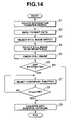
- FIG. 14is a flowchart showing a method for storing data held by the endoscopic system in FIG. 1 into a hospital network through the anesthesia-apparatus related system;
- FIG. 15is a block diagram showing a construction of a system controller according to a second embodiment of the present invention.
- FIG. 17is a diagram showing a first operation screen to be displayed on a centralized operation panel of the anesthesia-apparatus related system in FIG. 16 ;
- FIG. 18is a diagram showing a second operation screen to be displayed on the centralized operation panel of the anesthesia-apparatus related system in FIG. 16 ;
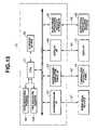
- FIG. 19is a diagram showing a third operation screen to be displayed on the centralized operation panel of the anesthesia-apparatus related system in FIG. 16 ;
- FIG. 20is a diagram showing a fourth operation screen to be displayed on the centralized operation panel of the anesthesia-apparatus related system in FIG. 16 ;
- FIG. 21is a diagram showing a fifth operation screen to be displayed on the centralized operation panel of the anesthesia-apparatus related system in FIG. 16 ;
- FIG. 23is a diagram showing a seventh operation screen to be displayed on the centralized operation panel of the anesthesia-apparatus related system in FIG. 16 ;
- FIG. 24is a diagram showing an eighth operation screen to be displayed on the centralized operation panel of the anesthesia-apparatus related system in FIG. 16 ;
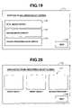
- FIG. 25is a first flowchart showing a method for associating and storing, in a hospital network, data indicating an abnormal value and data held in the endoscopic system at that time when information in the anesthesia-apparatus related system in FIG. 16 indicates the abnormal value;
- FIG. 26is a second flowchart showing a method for associating and storing, in a hospital network, data indicating an abnormal value and data held in the endoscopic system at that time when information in the anesthesia-apparatus related system in FIG. 16 indicates the abnormal value.
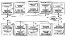
- a hospitalhas multiple operating rooms A to J each provided with an anesthesia-apparatus related system 48 .
- the anesthesia-apparatus related system 48is connected to a hospital network 44 managed by a server 47 through a communication circuit 45 such as a LAN cable.
- the anesthesia-apparatus related system 48is also connected to an endoscopic system 1 through a cable, not shown.
- the anesthesia-apparatus related system 48can interactively communicate with the endoscopic system 1 .
- the server 47includes a recording device, not shown.
- the endoscopic system 1has a first trolley 4 and a second trolley 5 on both sides of an operating table 2 on which a patient 3 lies down. Multiple endoscope peripheral apparatus for performing observation, tests, treatments, recording and so on are placed on these trolleys 4 and 5 .
- the first trolley 4includes a first TV camera device 6 , a first light source device 7 , a high frequency cauterizing device (called electric surgical knife hereinafter) 8 , a pneumoperitoneum apparatus 9 , a video printer 10 , a first display 12 , a centralized operation panel 14 and a system controller 15 and the like.
- the centralized operation panel 14is positioned in an unsterilized area so that a nurse can concentrate upon operating medical equipment.
- the centralized operation panel 14has a pointing device, not shown, such as a mouse and a touch panel.
- the devices including the first TV camera device 6 , the first light source device 7 , the high-frequency cauterizing device (called electric surgical knife, hereinafter) 8 , the pneumoperitoneum apparatus 9 , the video printer 10 , the first display 12 , the centralized operation panel 14 and the likeare connected to the system controller 15 through a cable, which will be described later.
- the apparatus including the first TV camera device 6 , the first light source device 7 , the high-frequency cauterizing device (called electric surgical knife, hereinafter) 8 , the pneumoperitoneum apparatus 9 , the video printer 10 , the first display 12 , the centralized operation panel 14 and the system controller 15 and the likecan communicate with the system controller 15 interactively.
- the first light source device 7is connected to a first endoscope 17 through a light-guide cable 16 for transmitting illumination light.
- the first light source device 7is arranged to supply illumination light to a light guide of the first endoscope 17 .
- the first endoscope 17has an insert portion to be inserted into the abdominal region of the patient 3 .
- the illumination light from the first light source device 7illuminates an affected part within the abdominal region of the patient 3 .
- the first endoscope 17captures reflected light from the illuminated affected part, for example, within the abdominal region of the patient 3 by using an observation optical device and transmits the captured light as an endoscopic image to an eyepiece.
- a first camera head 19 including an imaging elementis attached to an eyepiece of the first endoscope 17 .
- the first camera head 19picks up an endoscopic image supplied from the eyepiece of the first endoscope 17 by using incorporated the imaging element, not shown, and outputs imaging signals.
- the imaging signals from the first camera head 19are transmitted to the first TV camera device 6 through a camera cable 20 .
- the first TV camera device 6generates video signals by processing the received imaging signals in a signal processing circuit, not shown.
- the first TV camera device 6outputs the video signals to the first display 12 through the system controller 15 and can display the endoscopic image of the affected part, for example.
- the system controller 15includes an external-media recording device, not shown.
- the system controller 15can thus output to the first display 12 and display thereon image data recorded in an external recording medium.
- the system controller 15is also connected to a communication circuit 45 provided in a hospital, not shown, through a cable, not shown.
- the system controller 15can thus output to the first display 12 and display thereon image data, for example, recorded in a recording device of the server 47 connecting to the communication circuit 45 .
- a CO2 cylinder 21is connected to the pneumoperitoneum apparatus 9 .
- the pneumoperitoneum apparatus 9can supply CO2 gas into the abdominal region of the patient 3 through a pneumoperitoneum tube 22 extending from the pneumoperitoneum apparatus 9 to the patient 3 .
- the second trolley 5includes a second TV camera device 23 , a second light source device 24 , an ultrasonic processing device 25 , a VTR 26 , a second display 27 , a centralized display panel 28 and a relay unit 29 and the like.
- the devices including the second TV camera device 23 , the second light source device 24 , the ultrasonic processing device 25 , the VTR 26 , the second display 27 , the centralized display panel 28 and the likeare connected to the relay unit 29 through a cable, not shown, and can interactively communicate with the relay unit 29 .
- the second endoscope 32has an insert portion to be inserted into the abdominal region of the patient 3 .
- the illumination light from the second light source device 24illuminates an affected part within the abdominal region of the patient 3 .
- the second endoscope 32captures light reflected from the illuminated affected part, for example, within the abdominal region of the patient 3 by using an observation optical device and transmits the captured light as an endoscopic image to an eyepiece.
- a second camera head 33 including an imaging elementis attached to the eyepiece of the second endoscope 32 .
- the second camera head 33picks up an endoscopic image supplied from the eyepiece of the second endoscope 32 , by using the incorporated imaging element, not shown, and outputs imaging signals.
- the imaging signals from the second camera head 33are transmitted to the second TV camera device 23 through a camera cable 34 .
- the second TV camera device 23generates video signals by processing the received imaging signals in a signal processing circuit, not shown.
- the second TV camera device 23outputs the video signals to the second display 27 through the relay unit 29 and can display the endoscopic image of the affected part, for example.
- Dr. remote controlDr. remote control 35 to be used by an operator for manipulating equipment from an unsterilized area is also connected to the system controller 15 .
- a microphone 36can be connected to the system controller 15 .
- the system controller 15recognizes the voice input from the microphone 36 and can control devices through the voice of an operator.
- a foot-switch 37is connected to the ultrasonic processing device 25 through a cable 38 .
- the centralized operation panel 14 , the first TV camera device 6 , the first light source device 7 , the electric surgical knife 8 , the pneumoperitoneum apparatus 9 , the video printer 10 and the first display 12are connected to the system controller 15 through a communication cable 40 and can exchange data and video signals with the system controller 15 .
- the second TV camera device 23 , the second light source device 24 , the ultrasonic processing device 25 , the VTR 26 and the second display 27are connected to the relay unit 29 through the communication cable 41 and can exchange data and video signals with the relay unit 29 .
- the relay unit 29is also connected to the system controller 15 through the system cable 30 (see FIG. 2 ).
- the centralized operation panel 14is connected to the system controller 15 through a centralized operation panel cable 42 .
- the microphone 36is connected to the system controller 15 through a headset cable 36 b .
- the Dr. remote control 35is connected to the system controller 15 through a remote-control cable 35 b.
- the centralized display panel 13is connected to the system controller 15 through a system cable 46 a .
- the centralized display panel 28is also connected to the system controller 15 through a system cable 46 b .
- the anesthesia-apparatus related system 48is further connected to the system controller 15 through a system cable 49 .
- FIG. 4shows an internal construction of the system controller 15 .
- the system controller 15 provided in an operating roomincludes a CPU 51 , a communication interface (abbreviated to I/F, hereinafter) 52 , a centralized operation panel I/F 53 , a display I/F 54 , an anesthesia-apparatus related system I/F 55 and a storage device 56 .
- the system controller 15is connected to the medical devices through a communication cable 57 by using the communication I/F 52 .
- the system controller 15is connected to the centralized operation panel 14 through the centralized operation panel cable 42 by using the centralized operation panel I/F 53 .
- the system controller 15is connected to the display 12 through the communication cable 40 by using the display I/F 54 .
- the system controller 15is connected to the anesthesia-apparatus related system 48 through the system cable 49 by using the anesthesia-apparatus related system I/F 55 .
- the I/Fs 34 to. 37 and the storage device 56are connected to the CPU 51 and are centrally controlled by the CPU 51 .
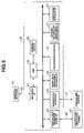
- FIG. 5shows an internal construction of the anesthesia-apparatus related system 48 .
- the anesthesia-apparatus related system 48 provided in an operating roomincludes a CPU 58 , a heart rate measuring instrument 59 , a sphygmomanometer 60 , an oxygen saturation measuring instrument 61 , an anesthesia device 62 , a centralized operation panel I/F 63 , a network I/F 64 , an endoscopic system I/F 65 and a storage device 66 .
- the anesthesia-apparatus related system 48is connected to the endoscopic system 1 through the system cable 49 by using the endoscopic system I/F 65 .
- the anesthesia-apparatus related system 48is connected to the hospital network 44 through the communication circuit 45 by using the network I/F 64 .
- the centralized operation panel I/F 63 , the network I/F 64 , the heart rate measuring instrument 59 , the sphygmomanometer 60 , the oxygen saturation measuring instrument 61 , the anesthesia device 62 and the storage device 66are connected to the CPU 58 and are centrally controlled by the CPU 58 .
- the network I/F 64 and the endoscopic system I/F 65are included in a transceiver while the CPU 58 is included in an information generating portion.
- FIGS. 6 to 13show different kinds of operation screens on a centralized operation panel 67 of the anesthesia-apparatus related system 48 .
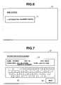
- FIG. 6shows a main screen 70 .
- the main screen 70has an information transfer switch 71 .
- the information transfer switch 71is selected on the main screen 70 on the centralized operation panel 67 , the main screen 70 is switched to a patient-data input screen 72 shown in FIG. 7 . That is, the centralized operation panel 67 displays the patient-data input screen 72 .
- FIG. 7shows the patient-data input screen 72 .
- the patient-data input screen 72has a patient-data input field 73 , a keyboard switch 74 and a NEXT switch 75 .
- the patient-data input screen 72is switched to an information-to-be-recorded select screen 76 shown in FIG. 8 . That is, the centralized operation panel 67 displays the information-to-be-recorded select screen 76 .
- FIG. 11shows the information add screen 85 .
- the information add screen 85is a screen for selecting whether data of the anesthesia-apparatus related system 48 is added to selected registered data or not.
- the information add screen 85has an YES switch 86 and a NO switch 87 .
- FIG. 12shows the additional function select screen 88 .
- the additional function select screen 88is a screen for adding data of the anesthesia-apparatus related system 48 to selected registered data.
- the additional function select screen 88has a heart rate switch 89 , a blood pressure switch 90 , an oxygen saturation switch 91 and a NEXT switch 92 .
- the centralized operation panel 67displays an information-to-be-registered checking screen 93 shown in FIG. 13 .
- a still image to be registeredis displayed on the recorded-information display area 94 .
- Input patient datais displayed on the patient-data display area 95 .
- Information on a selected functionis displayed on the data display area 96 .
- a method for recording and storing data held by the endoscopic system 1 into the recording device of the server 47 connected to the hospital network 44 through the anesthesia-apparatus related system 48will be described with reference to FIG. 7 .
- the CPU 58receives patient data input on the patient-data input screen 72 by an operator through the keyboard switch 74 .
- “KONISHI”, “26”, “male”, “gallbladder removal surgery” and “Jul. 23, 2002”are input to the name, age, sex, operation and date fields, respectively, on the patient-data input screen 72 .
- the CPU 58causes the information-to-be-recorded select screen 76 shown in FIG. 8 to be displayed.
- step S 5when the still image to be registered is checked by an operator and the NEXT switch 83 is selected on the still-image checking screen 81 , the CPU 58 causes the information add screen 85 shown in FIG. 11 to be displayed.
- the CPU 58receives the selection by an operator on whether the information of the anesthesia-apparatus related system 48 is added to registered information or not.
- the CPU 58receives the selection, by an operator, of a function to be added.
- the heart rate switch 89 and the blood pressure switch 90are selected, for example, on the additional function select screen 88 , and data of the two switches 89 and 90 are added.
- the CPU 58receives the selection, by an operator, of whether the selected information is to be registered with the storage device of the server 47 connecting to the hospital network 44 or not.
- the CPU 58When the selected information is registered with the hospital network 44 on the information-to-be-registered checking screen 93 , the CPU 58 receives the selection of the register switch 97 by an operator. Then, the processing goes to step S 9 . At step S 9 , the CPU 58 registers the selected still image, patient data, heart rate and blood pressure with the storage device of the server 47 connecting to the hospital network 44 .
- FIG. 16shows an internal construction of an anesthesia-apparatus related system 48 .
- the anesthesia-apparatus related system 48has an abnormality detecting sensor 101 , a code managing portion 102 and a time managing portion 103 , which are all connected to the CPU 58 , in addition to the construction according to the first embodiment.
- FIG. 18shows an upper limit value/lower limit value input screen 106 .
- the upper limit value/lower limit value input screen 106has an upper limit input field 107 , a lower limit value input field 108 , a keyboard switch 109 and a NEXT switch 110 .
- Upper limit and lower limit values of a heart rate, blood pressure and oxygen saturationare input on the upper limit value/lower limit value input screen 106 on the centralized operation panel 67 through the keyboard switch 109 .
- the centralized operation panel 67displays a function-to-be-linked select screen 111 shown in FIG. 19 .
- FIG. 19shows the function-to-be-linked select screen 111 .
- the function-to-be-linked select screen 111has a still image switch 112 , a moving image switch 113 , a device operational data switch 114 and a NEXT switch 115 .
- a function to be linkedis selected on the function-to-be-linked select screen 111 on the centralized operation panel 67 , a function for recording an abnormality if detected is set.
- FIG. 20shows an information-to-be-registered select screen 116 .
- the information-to-be-registered select screen 116has an information-to-be-registered select switch 117 and a NEXT switch 118 .
- a function to be linkedis selected on the information-to-be-registered select screen 116 on the centralized operation panel 67 , a function for recording an abnormality, if detected, is set.
- the centralized operation panel 67When the NEXT switch 118 is selected on the information-to-be-registered select screen 116 , the centralized operation panel 67 further displays a detail screen (before addition) 119 shown in FIG. 21 .
- FIG. 21shows the detail screen (before addition) 119 .
- the detail screen (before addition) 119has a NEXT switch 120 and a BACK switch 121 .
- the centralized operation panel 67displays an information-to-be-added select screen 122 shown in FIG. 22 .
- the centralized operation panel 67displays the information-to-be-registered select screen 116 in FIG. 20 again.
- FIG. 22shows the information-to-be-added select screen 122 .
- the information-to-be-added select screen 122has an information-to-be-added select switch 123 and a NEXT switch 124 .
- the centralized operation panel 67displays a detail screen (after addition) 125 shown in FIG. 23 .
- FIG. 23shows the detail screen (after addition) 125 .
- the detail screen (after addition) 125has a registered information display area 126 , a NEXT switch 127 and a BACK switch 128 .
- the centralized operation panel 67displays a network registration screen 129 shown in FIG. 24 .
- the centralized operation panel 67displays the information-to-be-added select screen 122 in FIG. 22 again.
- FIG. 24shows the network registration screen 129 .
- the network registration screen 129has an YES switch 130 and a NO switch 131 .
- the YES switch 130is selected on the network registration screen 129 on the centralized operation panel 67 , information is registered with the recording device of a server 47 connected to a hospital network 44 .
- the centralized operation panel 67displays the detail screen (after addition) 125 in FIG. 23 again.
- FIGS. 25 and 26show a method for storing data indicating an abnormal value and data held by the endoscopic system 1 at that time in the hospital network 44 in association when information in the anesthesia-apparatus related system 48 indicates the abnormal value.
- the CPU 58 of the anesthesia-apparatus related system 48causes a main screen 104 shown in FIG. 17 to be displayed on the centralized operation panel 67 .
- the CPU 58causes a patient-data input screen 72 shown in FIG. 7 to be displayed.
- the CPU 58receives patient data input by an operator from the keyboard switch 74 .
- “KONISHI”, “26”, “male”, “gallbladder removal surgery” and “Jul. 23, 2002”are input to the name, age, sex, operation and date fields, respectively, on the patient-data input screen 72 .
- the CPU 58receives the upper limit value and lower limit value of information in the anesthesia-apparatus related system 48 , which are input on the upper limit value/lower limit value input screen 106 by an operator.
- the heart rate, blood pressure and oxygen saturationare set to 60 to 90 times/min., 40 to 200 mmHg and 90 to 105%, respectively, for example, on the upper limit value/lower limit value input screen 106 .
- the CPU 58causes the function-to-be-linked select screen 111 shown in FIG. 19 to be displayed.
- the CPU 58receives on the function-to-be-linked select screen 111 , the selection, by an operator, of a function within the endoscopic system 1 for recording an abnormality, if detected, that is, a select function switch to be linked.
- the still image switch 112is selected on the function-to-be-linked select screen 111 .
- step S 35the CPU 58 starts measuring information in the anesthesia-apparatus related system 48 and goes to step S 36 .
- the CPU 58receives the determination, by an abnormality detecting sensor 101 , on whether or not any abnormality has occurred in the information in the anesthesia-apparatus related system 48 .
- the processinggoes to step S 37 .
- the CPU 58returns to step S 35 .
- step S 37when the abnormality detecting sensor 101 detects an abnormality, the CPU 58 files the data before and after the detection.
- data from five minutes before the occurrence of an abnormality to five minutes after the abnormality detectionis stored in the storage device 66 as one file. Then, the processing goes to step S 38 .
- step S 38the CPU 58 causes the code managing portion 102 to assign a Warning code to a file recorded in the storage device 66 .
- a Warning code 1is assigned thereto, and the processing then goes to step S 39 .
- step S 41the CPU 58 starts a function to be selected as a function to be linked.
- a still imageis shot and is recorded in the storage device 56 of the endoscopic system 1 .
- the Warning code 1 transmitted from the anesthesia-apparatus related system 48is assigned to the recorded information.
- the code managing portion 99also assigns the time when the still image is shot by using the time managing portion 100 to the recorded information. Then, the processing goes to step S 42 .
- step S 42the CPU 58 determines whether or not a predetermined period of time has passed from the record of the function to be selected as a function to be linked. If the predetermined period of time has passed, the CPU 58 goes to step S 41 . If the predetermined period of time has not passed, the CPU 58 goes to step S 43 .
- step S 43the CPU 58 checks whether or not a predetermined period of time has passed from the detection of an abnormality. If the predetermined period of time has passed, the CPU 58 goes to step S 44 . If the predetermined period of time has not passed, the CPU 58 returns to step S 42 .
- the CPU 58causes the information-to-be-registered select screen 116 shown in FIG. 20 to be displayed.
- the CPU 58causes the detail screen (before addition) 119 shown in FIG. 21 to be displayed.
- a blood pressure 1for example, is selected.
- the CPU 58causes the detail of blood-pressure information to be registered to be displayed on the detail screen (before addition) 119 .
- the CPU 58causes the information-to-be-added select screen 122 shown in FIG. 22 to be displayed on the detail screen (before addition) 119 in response to the selection of the NEXT switch 120 by an operator.
- step S 46when the information to be added is selected on the information-to-be-added select screen 122 and when the information-to-be-added select switch 123 is selected by an operator and the NEXT switch 124 is selected, the CPU 58 causes the detail screen (after addition) 125 shown in FIG. 23 to be displayed and goes to step S 47 .
- step S 48the CPU 58 adds to the blood pressure information and displays on the information-to-be-added select screen 122 the still image having the same Warning code as that of the blood pressure 1 .
- step S 48the CPU 58 registers the selected information with the recording device of the server 47 connected to the hospital network 44 .
- an abnormal condition and information held by an endoscopic system at that timecan be associated and be recorded chronologically.
- the labor after an operationcan be largely reduced.
Landscapes
- Health & Medical Sciences (AREA)
- Life Sciences & Earth Sciences (AREA)
- Surgery (AREA)
- Biomedical Technology (AREA)
- Medical Informatics (AREA)
- Optics & Photonics (AREA)
- Pathology (AREA)
- Radiology & Medical Imaging (AREA)
- Biophysics (AREA)
- Engineering & Computer Science (AREA)
- Physics & Mathematics (AREA)
- Heart & Thoracic Surgery (AREA)
- Nuclear Medicine, Radiotherapy & Molecular Imaging (AREA)
- Molecular Biology (AREA)
- Animal Behavior & Ethology (AREA)
- General Health & Medical Sciences (AREA)
- Public Health (AREA)
- Veterinary Medicine (AREA)
- Endoscopes (AREA)
- Medical Treatment And Welfare Office Work (AREA)
Abstract
Description
This application claims benefit of Japanese Applications No. 2003-62049 filed in Japan on Mar. 7, 2003, the contents of which are incorporated by this reference.
1. Field of the Invention
The present invention relates to an endoscopic surgical system for remotely supporting surgery.
2. Related Art Statement
Recently, an endoscopic apparatus is widely used. The endoscopic apparatus may be used for observing organs within a body cavity by inserting a long and narrow insert portion into the body cavity and/or for performing different kinds of treatments and procedures by using a treating device being inserted into a treating-device insert channel as needed.
An endoscopic surgical system using the endoscope is used in an equipment system having various data/images in an operating room.
For example, according to a conventional technology as disclosed in Japanese Laid-Open Patent Publication No. 2000-276540, information such as medical treatment information of patients and operational information for endoscopic image surgical apparatus can be stored.
In such a conventional endoscopic surgical system, anesthesia-related apparatus and endoscope-related apparatus need to hold a large amount of data and become more complicated. In the conventional endoscopic surgical system, an anesthesia-related apparatus and an endoscope-related apparatus are connected to a network separately and may transfer, for example, data independently.
An endoscopic surgical system according to the present invention includes an endoscopic system provided in an operating room and usable with an anesthesia-apparatus related system connected to a predetermined communication circuit, a transceiver provided in the anesthesia-apparatus related system, which can send and receive information, and an information creating portion for creating third information by associating first information sent from the anesthesia-apparatus related system through the transceiver and second information detected in the endoscopic system with a same patient.
An endoscopic surgical system according to the present invention includes an anesthesia-apparatus related system having an anesthesia information recording portion for chronologically and sequentially recording anesthesia-related information relating to anesthesia in an operation, an endoscopic system having an image recording portion for chronologically and sequentially recording operated-part image information of a patient, a communication portion for communicating between the anesthesia-apparatus related system and the endoscopic system, an image-read-out control portion provided in the endoscopic system for reading out and outputting to the communication portion the operated-part image information recorded in the image recording portion based on time information communicated from the anesthesia-apparatus related system to the endoscopic system by the communication portion, and a recording control portion provided in the anesthesia-apparatus related system for controlling the anesthesia information recording portion to record the operated-part image information sent from the endoscopic system to the anesthesia-apparatus related system through the communication portion under the control of the image-read-out control portion in connection with the anesthesia-related information of a same patient.
An endoscopic surgical system according to the present invention includes an information transfer select portion for selecting whether or not information of an anesthesia-apparatus related system is transferred to a recording device provided in a server connecting to a hospital network, an information-to-be-recorded select portion for selecting whether or not information of the anesthesia-apparatus related system is added to the recording device of the server connecting to the hospital network, an information-to-be-recorded checking portion for checking the information of the anesthesia-apparatus related system, which is selected in the information-to-be-recorded select portion, and an information-to-be-recorded adding portion for registering the information of the anesthesia-apparatus related system, which is checked in the information-to-be-recorded checking portion, with the recording device of the server connected to the hospital network.
An endoscopic surgical system according to the present invention includes an upper limit value/lower limit value input portion for receiving inputs of an upper limit value and lower limit value of information of an anesthesia-apparatus related system, an abnormality detecting portion for detecting an abnormality of the anesthesia-apparatus related system based on the upper limit value and lower limit value, which are input in the upper limit value/lower limit value input portion, a function-to-be-linked select portion for, when an abnormality of the anesthesia-apparatus related system is detected by the abnormality detecting portion, selecting a function in the endoscopic system to be recorded in connection with the abnormality of the anesthesia-apparatus related system, an abnormality recording portion for implementing the function in the endoscopic system, which is selected in the function-to-be-linked select portion, and for recording the abnormality of the anesthesia-apparatus related system, and a filing portion for filing the information before and after the detection of the abnormality, which is recorded by the abnormality recording portion.
Embodiments of the present invention will be described below with reference to drawings.
[First Embodiment]
According to an endoscopic surgical system of this embodiment, as shown inFIG. 1 , a hospital has multiple operating rooms A to J each provided with an anesthesia-apparatus relatedsystem 48.
The anesthesia-apparatus relatedsystem 48 is connected to ahospital network 44 managed by aserver 47 through acommunication circuit 45 such as a LAN cable. The anesthesia-apparatus relatedsystem 48 is also connected to anendoscopic system 1 through a cable, not shown. The anesthesia-apparatus relatedsystem 48 can interactively communicate with theendoscopic system 1. Theserver 47 includes a recording device, not shown.
As shown inFIG. 2 , theendoscopic system 1 has afirst trolley 4 and a second trolley5 on both sides of an operating table2 on which apatient 3 lies down. Multiple endoscope peripheral apparatus for performing observation, tests, treatments, recording and so on are placed on thesetrolleys 4 and5.
Thefirst trolley 4 includes a firstTV camera device 6, a firstlight source device 7, a high frequency cauterizing device (called electric surgical knife hereinafter)8, apneumoperitoneum apparatus 9, avideo printer 10, afirst display 12, acentralized operation panel 14 and asystem controller 15 and the like. Thecentralized operation panel 14 is positioned in an unsterilized area so that a nurse can concentrate upon operating medical equipment. Thecentralized operation panel 14 has a pointing device, not shown, such as a mouse and a touch panel.
The devices including the firstTV camera device 6, the firstlight source device 7, the high-frequency cauterizing device (called electric surgical knife, hereinafter)8, thepneumoperitoneum apparatus 9, thevideo printer 10, thefirst display 12, thecentralized operation panel 14 and the like are connected to thesystem controller 15 through a cable, which will be described later. The apparatus including the firstTV camera device 6, the firstlight source device 7, the high-frequency cauterizing device (called electric surgical knife, hereinafter)8, thepneumoperitoneum apparatus 9, thevideo printer 10, thefirst display 12, thecentralized operation panel 14 and thesystem controller 15 and the like can communicate with thesystem controller 15 interactively.
The firstlight source device 7 is connected to afirst endoscope 17 through a light-guide cable 16 for transmitting illumination light. The firstlight source device 7 is arranged to supply illumination light to a light guide of thefirst endoscope 17.
Thefirst endoscope 17 has an insert portion to be inserted into the abdominal region of thepatient 3. The illumination light from the firstlight source device 7 illuminates an affected part within the abdominal region of thepatient 3.
Thefirst endoscope 17 captures reflected light from the illuminated affected part, for example, within the abdominal region of thepatient 3 by using an observation optical device and transmits the captured light as an endoscopic image to an eyepiece.
Afirst camera head 19 including an imaging element is attached to an eyepiece of thefirst endoscope 17. Thefirst camera head 19 picks up an endoscopic image supplied from the eyepiece of thefirst endoscope 17 by using incorporated the imaging element, not shown, and outputs imaging signals.
The imaging signals from thefirst camera head 19 are transmitted to the firstTV camera device 6 through acamera cable 20. The firstTV camera device 6 generates video signals by processing the received imaging signals in a signal processing circuit, not shown. The firstTV camera device 6 outputs the video signals to thefirst display 12 through thesystem controller 15 and can display the endoscopic image of the affected part, for example.
Thesystem controller 15 includes an external-media recording device, not shown. Thesystem controller 15 can thus output to thefirst display 12 and display thereon image data recorded in an external recording medium.
Thesystem controller 15 is also connected to acommunication circuit 45 provided in a hospital, not shown, through a cable, not shown. Thesystem controller 15 can thus output to thefirst display 12 and display thereon image data, for example, recorded in a recording device of theserver 47 connecting to thecommunication circuit 45.
ACO2 cylinder 21 is connected to thepneumoperitoneum apparatus 9. Thus, thepneumoperitoneum apparatus 9 can supply CO2 gas into the abdominal region of thepatient 3 through apneumoperitoneum tube 22 extending from thepneumoperitoneum apparatus 9 to thepatient 3.
The second trolley5 includes a secondTV camera device 23, a secondlight source device 24, anultrasonic processing device 25, aVTR 26, asecond display 27, acentralized display panel 28 and arelay unit 29 and the like. The devices including the secondTV camera device 23, the secondlight source device 24, theultrasonic processing device 25, theVTR 26, thesecond display 27, thecentralized display panel 28 and the like are connected to therelay unit 29 through a cable, not shown, and can interactively communicate with therelay unit 29.
The secondlight source device 24 is connected to asecond endoscope 32 through a light-guide cable 31 for transmitting illumination light. The secondlight source device 24 is arranged to supply illumination light to a light guide of thesecond endoscope 32.
Thesecond endoscope 32 has an insert portion to be inserted into the abdominal region of thepatient 3. The illumination light from the secondlight source device 24 illuminates an affected part within the abdominal region of thepatient 3.
Thesecond endoscope 32 captures light reflected from the illuminated affected part, for example, within the abdominal region of thepatient 3 by using an observation optical device and transmits the captured light as an endoscopic image to an eyepiece.
Asecond camera head 33 including an imaging element is attached to the eyepiece of thesecond endoscope 32. Thesecond camera head 33 picks up an endoscopic image supplied from the eyepiece of thesecond endoscope 32, by using the incorporated imaging element, not shown, and outputs imaging signals.
The imaging signals from thesecond camera head 33 are transmitted to the secondTV camera device 23 through acamera cable 34. The secondTV camera device 23 generates video signals by processing the received imaging signals in a signal processing circuit, not shown. The secondTV camera device 23 outputs the video signals to thesecond display 27 through therelay unit 29 and can display the endoscopic image of the affected part, for example.
Thesystem controller 15 and therelay unit 29 are connected through asystem cable 30. A Dr. remote controller (hereinafter, referred to as Dr. remote control)35 to be used by an operator for manipulating equipment from an unsterilized area is also connected to thesystem controller 15.
Furthermore, amicrophone 36 can be connected to thesystem controller 15. Thesystem controller 15 recognizes the voice input from themicrophone 36 and can control devices through the voice of an operator.
A foot-switch 37 is connected to theultrasonic processing device 25 through acable 38.
As shown inFIG. 3 , thecentralized operation panel 14, the firstTV camera device 6, the firstlight source device 7, the electricsurgical knife 8, thepneumoperitoneum apparatus 9, thevideo printer 10 and thefirst display 12 are connected to thesystem controller 15 through acommunication cable 40 and can exchange data and video signals with thesystem controller 15.
The secondTV camera device 23, the secondlight source device 24, theultrasonic processing device 25, theVTR 26 and thesecond display 27 are connected to therelay unit 29 through thecommunication cable 41 and can exchange data and video signals with therelay unit 29.
Therelay unit 29 is also connected to thesystem controller 15 through the system cable30 (seeFIG. 2 ).
Thecentralized operation panel 14 is connected to thesystem controller 15 through a centralizedoperation panel cable 42. Themicrophone 36 is connected to thesystem controller 15 through aheadset cable 36b. The Dr.remote control 35 is connected to thesystem controller 15 through a remote-control cable 35b.
Thecentralized display panel 13 is connected to thesystem controller 15 through asystem cable 46a. Thecentralized display panel 28 is also connected to thesystem controller 15 through asystem cable 46b. The anesthesia-apparatus relatedsystem 48 is further connected to thesystem controller 15 through asystem cable 49.
Thesystem controller 15 provided in an operating room includes aCPU 51, a communication interface (abbreviated to I/F, hereinafter)52, a centralized operation panel I/F 53, a display I/F 54, an anesthesia-apparatus related system I/F 55 and astorage device 56.
Thesystem controller 15 is connected to the medical devices through acommunication cable 57 by using the communication I/F 52. Thesystem controller 15 is connected to thecentralized operation panel 14 through the centralizedoperation panel cable 42 by using the centralized operation panel I/F 53. Thesystem controller 15 is connected to thedisplay 12 through thecommunication cable 40 by using the display I/F 54. Thesystem controller 15 is connected to the anesthesia-apparatus relatedsystem 48 through thesystem cable 49 by using the anesthesia-apparatus related system I/F 55.
The I/Fs 34 to.37 and thestorage device 56 are connected to theCPU 51 and are centrally controlled by theCPU 51.
The anesthesia-apparatus relatedsystem 48 provided in an operating room includes aCPU 58, a heartrate measuring instrument 59, asphygmomanometer 60, an oxygensaturation measuring instrument 61, ananesthesia device 62, a centralized operation panel I/F 63, a network I/F 64, an endoscopic system I/F 65 and astorage device 66.
The anesthesia-apparatus relatedsystem 48 is connected to theendoscopic system 1 through thesystem cable 49 by using the endoscopic system I/F 65. The anesthesia-apparatus relatedsystem 48 is connected to thehospital network 44 through thecommunication circuit 45 by using the network I/F 64.
The centralized operation panel I/F 63, the network I/F 64, the heartrate measuring instrument 59, thesphygmomanometer 60, the oxygensaturation measuring instrument 61, theanesthesia device 62 and thestorage device 66 are connected to theCPU 58 and are centrally controlled by theCPU 58.
In other words, the network I/F 64 and the endoscopic system I/F 65 are included in a transceiver while theCPU 58 is included in an information generating portion.
When theNEXT switch 83 is selected on the still-image checking screen 81, the still-image checking screen 81 is switched to an information addscreen 85 shown inFIG. 11 . That is, thecentralized operation panel 67 displays the information addscreen 85. On the other hand, when theBACK switch 84 is selected on the still-image checking screen 81, thecentralized operation panel 67 returns to the information-to-be-recordedselect screen 80 inFIG. 9 .
When theYES switch 86 is selected on the information addscreen 85, the information addscreen 85 is switched to an additional functionselect screen 88 shown inFIG. 12 . That is, thecentralized operation panel 67 displays the additional functionselect screen 88.
When theNO switch 87 is selected on the information addscreen 85 on thecentralized operation panel 67, selected information is registered with a recording device of theserver 47 through the anesthesia-apparatus relatedsystem 48 and the hospital network44 (seeFIG. 1 ).
When data to be added to registered information and then theNEXT switch 92 are selected on the additional functionselect screen 88, thecentralized operation panel 67 displays an information-to-be-registered checking screen 93 shown inFIG. 13 .
A still image to be registered is displayed on the recorded-information display area 94. Input patient data is displayed on the patient-data display area 95. Information on a selected function is displayed on thedata display area 96.
When theREGISTER switch 97 is selected on the information-to-be-registered checking screen 93 on thecentralized operation panel 67, data being displayed is stored in the recording device of theserver 47 through thehospital network 44. When theRETURN switch 98 is selected on the information-to-be-registered checking screen 93, thecentralized operation panel 67 displays the still-image checking screen 81 inFIG. 10 again.
A method for recording and storing data held by theendoscopic system 1 into the recording device of theserver 47 connected to thehospital network 44 through the anesthesia-apparatus relatedsystem 48 will be described with reference toFIG. 7 .
At step S1, theCPU 58 of the anesthesia-apparatus relatedsystem 48 causes thecentralized operation panel 67 to display themain screen 70 shown inFIG. 6 .
When theinformation transfer switch 71 is selected on themain screen 70 by an operator, theCPU 58 causes the patient-data input screen 72 shown inFIG. 7 to be displayed.
At step S2, theCPU 58 receives patient data input on the patient-data input screen 72 by an operator through thekeyboard switch 74. In this embodiment, “KONISHI”, “26”, “male”, “gallbladder removal surgery” and “Jul. 23, 2002” are input to the name, age, sex, operation and date fields, respectively, on the patient-data input screen 72.
When theNEXT switch 75 is selected on the patient-data input screen 72 by an operator, theCPU 58 causes the information-to-be-recordedselect screen 76 shown inFIG. 8 to be displayed.
At step S3, on the information-to-be-recordedselect screen 76, theCPU 58 receives the operator's selection of the function for registration in thehospital network 44. According to this embodiment, when the still-image switch 77 is selected on the information-to-be-recordedselect screen 76 by an operator in order to store a still image, for example, the information-to-be-recordedselect screen 80 for still images shown inFIG. 9 is displayed.
At step S4, on the information-to-be-recordedselect screen 80, theCPU 58 receives the operator's selection of the still image to be registered with the recording device of theserver 47 connecting to thehospital network 44. According to this embodiment, when astill image 1 is selected on the information-to-be-recordedselect screen 80, for example, the still-image checking screen 81 for thestill image 1 shown inFIG. 10 is displayed.
At step S5, when the still image to be registered is checked by an operator and theNEXT switch 83 is selected on the still-image checking screen 81, theCPU 58 causes the information addscreen 85 shown inFIG. 11 to be displayed.
At step S6, on the information addscreen 85, theCPU 58 receives the selection by an operator on whether the information of the anesthesia-apparatus relatedsystem 48 is added to registered information or not.
When theYES switch 86 is selected by an operator on the information addscreen 85, theCPU 58 causes the additional functionselect screen 88 shown inFIG. 12 to be displayed. On the other hand, when theNO switch 87 is selected by an operator on the information addscreen 85 on thecentralized operation panel 67, the processing goes to step S9.
At step S7, on the additional functionselect screen 88, theCPU 58 receives the selection, by an operator, of a function to be added. According to this embodiment, theheart rate switch 89 and theblood pressure switch 90 are selected, for example, on the additional functionselect screen 88, and data of the twoswitches
When theNEXT switch 92 is selected by an operator on the additional functionselect screen 88, theCPU 58 causes the information-to-be-registered checking screen 93 shown inFIG. 13 to be displayed.
At step S8, on the information-to-be-registered checking screen 93, theCPU 58 receives the selection, by an operator, of whether the selected information is to be registered with the storage device of theserver 47 connecting to thehospital network 44 or not.
When the selected information is registered with thehospital network 44 on the information-to-be-registered checking screen 93, theCPU 58 receives the selection of theregister switch 97 by an operator. Then, the processing goes to step S9. At step S9, theCPU 58 registers the selected still image, patient data, heart rate and blood pressure with the storage device of theserver 47 connecting to thehospital network 44.
According to this embodiment, data of theendoscopic system 1 is transferred to thehospital network 44 through the anesthesia-apparatus relatedsystem 48 so that data to be used in an operating room can be transferred through one path. Thus, the construction is simplified, and the ease of use can be improved.
[Second Embodiment]
Since a second embodiment is almost the same as the first embodiment, only differences therebetween will be described. The same reference numerals will be given to the same components, the description of which will be omitted hereinafter.
Thesystem controller 15 has acode managing portion 99 and atime managing portion 100, which are connected to theCPU 51 respectively, in addition to the construction according to the first embodiment.
The anesthesia-apparatus relatedsystem 48 has anabnormality detecting sensor 101, acode managing portion 102 and atime managing portion 103, which are all connected to theCPU 58, in addition to the construction according to the first embodiment.
Upper limit and lower limit values of a heart rate, blood pressure and oxygen saturation are input on the upper limit value/lower limitvalue input screen 106 on thecentralized operation panel 67 through thekeyboard switch 109. When theNEXT switch 110 is selected on the upper limit value/lower limitvalue input screen 106, thecentralized operation panel 67 displays a function-to-be-linkedselect screen 111 shown inFIG. 19 .
When theNEXT switch 118 is selected on the information-to-be-registeredselect screen 116, thecentralized operation panel 67 further displays a detail screen (before addition)119 shown inFIG. 21 .
When theBACK switch 121 is selected on the detail screen (before addition)119, thecentralized operation panel 67 displays the information-to-be-registeredselect screen 116 inFIG. 20 again.
When theBACK switch 128 is selected on the detail screen (after addition)125, thecentralized operation panel 67 displays the information-to-be-addedselect screen 122 inFIG. 22 again.
When theNO switch 131 is selected on thenetwork registration screen 129, thecentralized operation panel 67 displays the detail screen (after addition)125 inFIG. 23 again.
At step S31, theCPU 58 of the anesthesia-apparatus relatedsystem 48 causes amain screen 104 shown inFIG. 17 to be displayed on thecentralized operation panel 67. When theinformation link switch 105 is selected by an operator on themain screen 104, theCPU 58 causes a patient-data input screen 72 shown inFIG. 7 to be displayed.
At step S32, on the patient-data input screen 72, theCPU 58 receives patient data input by an operator from thekeyboard switch 74. In this embodiment, “KONISHI”, “26”, “male”, “gallbladder removal surgery” and “Jul. 23, 2002” are input to the name, age, sex, operation and date fields, respectively, on the patient-data input screen 72.
When the NEXT switch is selected on the patient-data input screen 72 by an operator, theCPU 58 causes the upper limit value/lower limitvalue input screen 106 shown inFIG. 18 to be displayed.
At step S33, theCPU 58 receives the upper limit value and lower limit value of information in the anesthesia-apparatus relatedsystem 48, which are input on the upper limit value/lower limitvalue input screen 106 by an operator. In this embodiment, the heart rate, blood pressure and oxygen saturation are set to 60 to 90 times/min., 40 to 200 mmHg and 90 to 105%, respectively, for example, on the upper limit value/lower limitvalue input screen 106.
When theNEXT switch 110 is selected on the upper limit value/lower limitvalue input screen 106 by an operator, theCPU 58 causes the function-to-be-linkedselect screen 111 shown inFIG. 19 to be displayed.
At step S34, theCPU 58 receives on the function-to-be-linkedselect screen 111, the selection, by an operator, of a function within theendoscopic system 1 for recording an abnormality, if detected, that is, a select function switch to be linked. According to this embodiment, thestill image switch 112 is selected on the function-to-be-linkedselect screen 111.
When theNEXT switch 115 is selected on the function-to-be-linkedselect screen 111 by an operator, theCPU 58 goes to step S35. At step S35, theCPU 58 starts measuring information in the anesthesia-apparatus relatedsystem 48 and goes to step S36.
At step S36, theCPU 58 receives the determination, by anabnormality detecting sensor 101, on whether or not any abnormality has occurred in the information in the anesthesia-apparatus relatedsystem 48. According to this embodiment, when theabnormality detecting sensor 101 detects an abnormality, for example, when the blood pressure value is above 200 mmHg, the processing goes to step S37. When theabnormality detecting sensor 101 detects no abnormalities, theCPU 58 returns to step S35.
At step S37, when theabnormality detecting sensor 101 detects an abnormality, theCPU 58 files the data before and after the detection. According to this embodiment, data from five minutes before the occurrence of an abnormality to five minutes after the abnormality detection, for example, is stored in thestorage device 66 as one file. Then, the processing goes to step S38.
At step S38, theCPU 58 causes thecode managing portion 102 to assign a Warning code to a file recorded in thestorage device 66. According to this embodiment, aWarning code 1 is assigned thereto, and the processing then goes to step S39.
At step S39, theCPU 58 sends the assignedWarning code 1 to theendoscopic system 1. Then, the processing goes to step S40. At step S40, theCPU 58 causes theCPU 51 of theendoscopic system 1 to receive theWarning code 1 and registers theWarning code 1 with thestorage device 56. Then, the processing goes to step S41.
At step S41, theCPU 58 starts a function to be selected as a function to be linked. According to this embodiment, a still image is shot and is recorded in thestorage device 56 of theendoscopic system 1. Then, theWarning code 1 transmitted from the anesthesia-apparatus relatedsystem 48 is assigned to the recorded information. Thecode managing portion 99 also assigns the time when the still image is shot by using thetime managing portion 100 to the recorded information. Then, the processing goes to step S42.
At step S42, theCPU 58 determines whether or not a predetermined period of time has passed from the record of the function to be selected as a function to be linked. If the predetermined period of time has passed, theCPU 58 goes to step S41. If the predetermined period of time has not passed, theCPU 58 goes to step S43.
At step S43, theCPU 58 checks whether or not a predetermined period of time has passed from the detection of an abnormality. If the predetermined period of time has passed, theCPU 58 goes to step S44. If the predetermined period of time has not passed, theCPU 58 returns to step S42.
At step S44, theCPU 58 causes the information-to-be-registeredselect screen 116 shown inFIG. 20 to be displayed. When the information to be registered with the recording device of theserver 47 connecting to thehospital network 44 is selected by an operator on the information-to-be-registeredselect screen 116 and theNEXT switch 118 is then selected, theCPU 58 causes the detail screen (before addition)119 shown inFIG. 21 to be displayed. In this embodiment, ablood pressure 1, for example, is selected.
At step S45, theCPU 58 causes the detail of blood-pressure information to be registered to be displayed on the detail screen (before addition)119. When the displayed information is registered with the recording device of theserver 47 connected to thehospital network 44, theCPU 58 causes the information-to-be-addedselect screen 122 shown inFIG. 22 to be displayed on the detail screen (before addition)119 in response to the selection of theNEXT switch 120 by an operator.
At step S46, when the information to be added is selected on the information-to-be-addedselect screen 122 and when the information-to-be-addedselect switch 123 is selected by an operator and theNEXT switch 124 is selected, theCPU 58 causes the detail screen (after addition)125 shown inFIG. 23 to be displayed and goes to step S47.
When theNEXT switch 124 is selected by an operator on the information-to-be-addedselect screen 122 instead of the selection of the information-to-be-addedselect switch 123, theCPU 58 goes to step S48. At step S47, theCPU 58 adds to the blood pressure information and displays on the information-to-be-addedselect screen 122 the still image having the same Warning code as that of theblood pressure 1.
When the displayed information is to be registered with thehospital network 44 on the information-to-be-addedselect screen 122, theCPU 58 goes to step S48 in response to the selection of theNEXT switch 127 by an operator. On the other hand, when theBACK switch 128 is selected by an operator on the information-to-be-addedselect screen 122, theCPU 58 returns to step S46. At step S48, theCPU 58 registers the selected information with the recording device of theserver 47 connected to thehospital network 44.
According to the second embodiment, in addition to the advantages of the first embodiment, an abnormal condition and information held by an endoscopic system at that time can be associated and be recorded chronologically. Thus, the labor after an operation can be largely reduced.
The present invention is not limited to the above-described embodiments, and various changes, modifications and the like thereof could be made without changing the principle of the present invention.
Having described the preferred embodiments of the invention referring to the accompanying drawing, it should be understood that the present invention is not limited to those precise embodiments and various changes and modification thereof could be made by one skilled in the art without departing from the spirit or scope of the invention as defined in the appended claims.
Claims (16)
1. An endoscopic surgical system, comprising;
an endoscopic system provided in an operating room and usable with an anesthesia-apparatus related system connected to a communication portion, said anesthesia-apparatus related system including an anesthesia administering apparatus for administering anesthesia to a patient;
a transceiver provided in the anesthesia-apparatus related system, which can send and receive information; and
an information creating portion for creating combined anesthesia-endoscopic image information by associating anesthesia information sent from the anesthesia-apparatus related system through the transceiver and endoscopic image information detected in the endoscopic system with a same patient, the information creating portion comprising:
an information transfer select portion for providing a user transfer selection interface on a display screen for selecting whether or not the endoscopic image information is transferred to a recording device provided in a server connected to a hospital network;
an information-to-be-recorded select portion for providing a user recording selection interface on the display screen for selecting the information of the anesthesia-apparatus related system to be added to the transferred endoscopic image information;
an information-to-be-recorded checking portion for providing a user checking interface on the display screen for checking the information of the anesthesia-apparatus related system, which is selected in the information-to-be-recorded select portion; and
an information-to-be-recorded adding portion for registering the information of the anesthesia-apparatus related system, which is checked in the information-to-be-recorded checking portion, with the recording device of the server connecting to the hospital network.
2. An endoscopic surgical system according toclaim 1 , further comprising:
the anesthesia-apparatus related system having an anesthesia information recording portion for chronologically and sequentially recording anesthesia related information, which is the anesthesia information related to anesthesia in an operation;
the endoscopic system having an image recording portion for chronologically and sequentially recording an operated-part image information, which is the endoscopic image information of the patient; and
the information creating portion having an image-read-out control portion provided in the anesthesia apparatus related system for reading out and outputting to the communication portion operated-part image information recorded in the image recording portion based on time information communicated from the anesthesia-apparatus related system by the communication portion; and
a recording control portion provided in the anesthesia-apparatus related system for controlling the anesthesia information recording portion so that the operated-part image information sent from the endoscopic system to the anesthesia-apparatus related system through the communication portion can be associated with the anesthesia related information of a same patient and can be recorded as the combined anesthesia-endoscopic image information.
3. An endoscopic surgical system according toclaim 1 ,
wherein the anesthesia-apparatus related system is provided in each of multiple operating rooms separately and is connected to a hospital network managed by a server over the communication portion.
4. An endoscopic surgical system according toclaim 3 , wherein the information creating portion transfers information of the endoscopic system to the hospital network through the anesthesia-apparatus related system and stores the information in the server.
5. An endoscopic surgical system according toclaim 3 , wherein, a warning code is issued when an abnormality is detected in the anesthesia information, and based on the warning code, the information creating portion associates the anesthesia information with the endoscopic image information, the combined anesthesia-endoscopic image information being subsequently transferred to the hospital network and stored-in the server.
6. An endoscopic surgical system according toclaim 1 , further comprising:
the anesthesia-apparatus related system having a heart rate measuring instrument, a sphygmomanometer, and an oxygen saturation measuring instrument;
the information creating portion being a CPU; and
the transceiver including a centralized operation panel interface, a network interface and an endoscopic system interface.
7. An endoscopic surgical system according toclaim 1 , wherein the information creating portion is a system controller provided in an operating room, and the system controller includes a CPU, a communication interface, a centralized operation panel interface, a display interface, an anesthesia-apparatus related system interface and a storage device.
8. An endoscopic surgical system according toclaim 1 , wherein the information creating portion has a patient information input portion for receiving inputs of patient information and adds information of the anesthesia-apparatus related system to patient information input though the patient information input portion.
9. An endoscopic surgical system according toclaim 8 , wherein the information creating portion comprises:
the information-to-be-recorded select portion for selecting whether or not operated-part image information or device operational information recorded in a storage device is added to the recording device provided in the server connected to the hospital network;
the information-to-be-recorded checking portion for checking the operated-part image information or device operational information selected by the information-to-be-recorded select portion; and
the information-to-be-recorded adding portion for registering the operated-part image information or device operational information checked by the information-to-be-recorded checking portion with the recording device of the server connecting to the hospital network.
10. An endoscopic surgical system according toclaim 9 , wherein the device operational information is heart-rate, blood-pressure and oxygen-saturation information.
11. An endoscopic surgical system according toclaim 8 , wherein the information creating portion further comprises:
an upper limit value/lower limit value input portion for being used to input an upper limit value and lower limit value of information of the anesthesia-apparatus related system;
an abnormality detecting portion for detecting an abnormality of the anesthesia-apparatus related system based on the upper limit value and lower limit value input by the upper limit value/lower limit value input portion;
a function-to-be-linked select portion for, when an abnormality of the anesthesia-apparatus related system is detected by the abnormality detecting portion, selecting a function within the endoscopic system to be recorded in connection with the abnormality of the anesthesia-apparatus related system;
an abnormality recording portion for implementing a function within the endoscopic system selected in the function-to-be-linked select portion and recording the abnormality of the anesthesia-apparatus related system; and
a filing portion for filing information before and after the detection of the abnormality recorded by the abnormality recording portion.
12. An endoscopic operation system according toclaim 11 , wherein:
the information-to-be-recorded select portion selects whether or not the information before and after the abnormality detection filed by the filing portion is added to the hospital network;
the information-to-be-recorded checking portion checks the information before and after the abnormality detection selected by the information-to-be-recorded select portion; and
the information-to-be-recorded adding portion registers the information before and after the abnormality detection checked by the information-to-be-recorded checking portion with the hospital network.
13. An endoscopic surgical system according toclaim 11 , the information creating portion further comprising:
a code managing portion for assigning a warning code to the information before and after the abnormality detection filed by the filing portion; and
an abnormality registration portion for sending to the endoscopic system and registering with the endoscopic system the information before and after the abnormality detection having the warning code assigned by the code managing portion.
14. An endoscopic surgical system according toclaim 11 , wherein the information creating portion includes a determination portion for determining whether or not a predetermined period of time has passed from the record of the information before and after the abnormality detection in the abnormality recording portion and for determining whether or not a predetermined period of time has passed from the detection of an abnormality of the anesthesia-apparatus related system by the abnormality detecting portion.
15. An endoscopic surgical system, comprising:
an anesthesia-apparatus related system having an anesthesia administering apparatus for administering anesthesia to a patient, and an anesthesia information recording portion for chronologically and sequentially recording anesthesia-related information relating to anesthesia in an operation;
an endoscopic system having an image recording portion for chronologically and sequentially recording operated-part image information of a patient;
an information creating portion provided in the anesthesia apparatus related system for creating combined anesthesia-endoscopic image information by associating anesthesia information sent from the anesthesia-apparatus related system and endoscopic image information detected in the endoscopic system with a same patient, the information creating portion comprising:
an information transfer select portion providing a user transfer selection interface on a display screen for selecting whether or not information of the anesthesia-apparatus related system is transferred to a recording device provided in a sewer connecting to a hospital network;
an information-to-be-recorded select portion for providing a user recording selection interface on the display screen for selecting whether or not information of the anesthesia-apparatus related system is added to the recording device of the server connecting
an information-to-be-recorded checking portion for providing a user checking interface on the display screen for checking the information of the anesthesia-apparatus related system, which is selected in the information-to-be-recorded select portion; and
an information-to-be-recorded adding portion for registering the information of the anesthesia-apparatus related system, which is checked in the information-to-be-recorded checking portion, with the recording device of the server connected to the hospital network;
a communication portion for communicating between the anesthesia-apparatus related system and the endoscopic system;
an image-read-out control portion provided in the endoscopic system for reading out and outputting to the communication portion the operated-part image information recorded in the image recording portion based on time information communicated from the anesthesia-apparatus related system to the endoscopic system by the communication portion; and
a recording control portion provided in the anesthesia-apparatus related system for controlling the anesthesia information recording portion to record the operated-part image information sent from the endoscopic system to the anesthesia-apparatus related system through the communication portion under the control of the image-read-out control portion in connection with the anesthesia-related information of a same patient.
16. An endoscopic surgical system, comprising:
an information creating portion provided in an anesthesia apparatus related system for creating combined anesthesia-endoscopic image information by associating anesthesia information sent from the anesthesia-apparatus related system and endoscopic image information detected in the endoscopic system with a same patient, said anesthesia apparatus related system including an anesthesia administering apparatus for administering anesthesia to a patient, the information creating portion comprising:
an information-to-be-recorded select portion for providing a user recording selection interface on a display screen for selecting whether or not the information before and after the abnormality detection, which is filed in the filing portion, is registered to information in a recording device provided in a server connected to a hospital network;
an information-to-be-recorded checking portion for providing a user checking interface on a display screen for checking the information before and after the abnormality detection, which is selected in the information-to-be-recorded select portion; and
an information-to-be-recorded adding portion for registering the information before and after the abnormality detection, which is checked in the information-to-be-recorded checking portion, with the recording device of the server connected to the hospital network;
an upper limit value/lower limit value input portion for receiving inputs of an upper limit value and lower limit value of information of the anesthesia-apparatus related system;
an abnormality detecting portion for detecting an abnormality of the anesthesia-apparatus related system based on the upper limit value and lower limit value, which are input in the upper limit value/lower limit value input portion;
a function-to-be-linked select portion for, when an abnormality of the anesthesia-apparatus related system is detected by the abnormality detecting portion, selecting a function in the endoscopic system to be recorded in connection with the abnormality of the anesthesia-apparatus related system;
an abnormality recording portion for implementing the function in the endoscopic system, which is selected in the function-to-be-linked select portion, and recording the abnormality of the anesthesia-apparatus related system; and
a filing portion for filing the information before and after the detection of the abnormality, which is recorded by the abnormality recording portion.
Applications Claiming Priority (2)
| Application Number | Priority Date | Filing Date | Title |
|---|---|---|---|
| JP2003062049AJP2004267461A (en) | 2003-03-07 | 2003-03-07 | Endoscopic surgery system |
| JP2003-062049 | 2003-03-07 |
Publications (2)
| Publication Number | Publication Date |
|---|---|
| US20050054896A1 US20050054896A1 (en) | 2005-03-10 |
| US7413541B2true US7413541B2 (en) | 2008-08-19 |
Family
ID=33124085
Family Applications (1)
| Application Number | Title | Priority Date | Filing Date |
|---|---|---|---|
| US10/792,240Expired - LifetimeUS7413541B2 (en) | 2003-03-07 | 2004-03-03 | Surgery support system for endoscopic surgery |
Country Status (2)
| Country | Link |
|---|---|
| US (1) | US7413541B2 (en) |
| JP (1) | JP2004267461A (en) |
Cited By (66)
| Publication number | Priority date | Publication date | Assignee | Title |
|---|---|---|---|---|
| US20060217591A1 (en)* | 2005-03-28 | 2006-09-28 | Fujinon Corporation | Electronic endoscope apparatus |
| US11589865B2 (en) | 2018-03-28 | 2023-02-28 | Cilag Gmbh International | Methods for controlling a powered surgical stapler that has separate rotary closure and firing systems |
| US11589932B2 (en) | 2017-12-28 | 2023-02-28 | Cilag Gmbh International | Usage and technique analysis of surgeon / staff performance against a baseline to optimize device utilization and performance for both current and future procedures |
| US11589915B2 (en) | 2018-03-08 | 2023-02-28 | Cilag Gmbh International | In-the-jaw classifier based on a model |
| US11601371B2 (en) | 2017-12-28 | 2023-03-07 | Cilag Gmbh International | Surgical network determination of prioritization of communication, interaction, or processing based on system or device needs |
| US11648022B2 (en) | 2017-10-30 | 2023-05-16 | Cilag Gmbh International | Surgical instrument systems comprising battery arrangements |
| US11659023B2 (en) | 2017-12-28 | 2023-05-23 | Cilag Gmbh International | Method of hub communication |
| US11666331B2 (en) | 2017-12-28 | 2023-06-06 | Cilag Gmbh International | Systems for detecting proximity of surgical end effector to cancerous tissue |
| US11672605B2 (en) | 2017-12-28 | 2023-06-13 | Cilag Gmbh International | Sterile field interactive control displays |
| US11678881B2 (en) | 2017-12-28 | 2023-06-20 | Cilag Gmbh International | Spatial awareness of surgical hubs in operating rooms |
| US11696760B2 (en) | 2017-12-28 | 2023-07-11 | Cilag Gmbh International | Safety systems for smart powered surgical stapling |
| US11701185B2 (en) | 2017-12-28 | 2023-07-18 | Cilag Gmbh International | Wireless pairing of a surgical device with another device within a sterile surgical field based on the usage and situational awareness of devices |
| US11701139B2 (en) | 2018-03-08 | 2023-07-18 | Cilag Gmbh International | Methods for controlling temperature in ultrasonic device |
| US11707293B2 (en) | 2018-03-08 | 2023-07-25 | Cilag Gmbh International | Ultrasonic sealing algorithm with temperature control |
| US11737668B2 (en) | 2017-12-28 | 2023-08-29 | Cilag Gmbh International | Communication hub and storage device for storing parameters and status of a surgical device to be shared with cloud based analytics systems |
| US11744604B2 (en) | 2017-12-28 | 2023-09-05 | Cilag Gmbh International | Surgical instrument with a hardware-only control circuit |
| US11751872B2 (en) | 2019-02-19 | 2023-09-12 | Cilag Gmbh International | Insertable deactivator element for surgical stapler lockouts |
| US11751958B2 (en) | 2017-12-28 | 2023-09-12 | Cilag Gmbh International | Surgical hub coordination of control and communication of operating room devices |
| US11771487B2 (en) | 2017-12-28 | 2023-10-03 | Cilag Gmbh International | Mechanisms for controlling different electromechanical systems of an electrosurgical instrument |
| US11775682B2 (en) | 2017-12-28 | 2023-10-03 | Cilag Gmbh International | Data stripping method to interrogate patient records and create anonymized record |
| US11779337B2 (en) | 2017-12-28 | 2023-10-10 | Cilag Gmbh International | Method of using reinforced flexible circuits with multiple sensors to optimize performance of radio frequency devices |
| US11786251B2 (en) | 2017-12-28 | 2023-10-17 | Cilag Gmbh International | Method for adaptive control schemes for surgical network control and interaction |
| US11786245B2 (en) | 2017-12-28 | 2023-10-17 | Cilag Gmbh International | Surgical systems with prioritized data transmission capabilities |
| US11801098B2 (en) | 2017-10-30 | 2023-10-31 | Cilag Gmbh International | Method of hub communication with surgical instrument systems |
| US11818052B2 (en) | 2017-12-28 | 2023-11-14 | Cilag Gmbh International | Surgical network determination of prioritization of communication, interaction, or processing based on system or device needs |
| US11832899B2 (en) | 2017-12-28 | 2023-12-05 | Cilag Gmbh International | Surgical systems with autonomously adjustable control programs |
| US11844579B2 (en) | 2017-12-28 | 2023-12-19 | Cilag Gmbh International | Adjustments based on airborne particle properties |
| US11857152B2 (en) | 2017-12-28 | 2024-01-02 | Cilag Gmbh International | Surgical hub spatial awareness to determine devices in operating theater |
| US11864728B2 (en) | 2017-12-28 | 2024-01-09 | Cilag Gmbh International | Characterization of tissue irregularities through the use of mono-chromatic light refractivity |
| US11871901B2 (en) | 2012-05-20 | 2024-01-16 | Cilag Gmbh International | Method for situational awareness for surgical network or surgical network connected device capable of adjusting function based on a sensed situation or usage |
| US11890065B2 (en) | 2017-12-28 | 2024-02-06 | Cilag Gmbh International | Surgical system to limit displacement |
| US11896322B2 (en) | 2017-12-28 | 2024-02-13 | Cilag Gmbh International | Sensing the patient position and contact utilizing the mono-polar return pad electrode to provide situational awareness to the hub |
| US11896443B2 (en) | 2017-12-28 | 2024-02-13 | Cilag Gmbh International | Control of a surgical system through a surgical barrier |
| US11903587B2 (en) | 2017-12-28 | 2024-02-20 | Cilag Gmbh International | Adjustment to the surgical stapling control based on situational awareness |
| US11903601B2 (en) | 2017-12-28 | 2024-02-20 | Cilag Gmbh International | Surgical instrument comprising a plurality of drive systems |
| US11911045B2 (en) | 2017-10-30 | 2024-02-27 | Cllag GmbH International | Method for operating a powered articulating multi-clip applier |
| US11925350B2 (en) | 2019-02-19 | 2024-03-12 | Cilag Gmbh International | Method for providing an authentication lockout in a surgical stapler with a replaceable cartridge |
| US11931027B2 (en) | 2018-03-28 | 2024-03-19 | Cilag Gmbh Interntional | Surgical instrument comprising an adaptive control system |
| US11937769B2 (en) | 2017-12-28 | 2024-03-26 | Cilag Gmbh International | Method of hub communication, processing, storage and display |
| US11969216B2 (en) | 2017-12-28 | 2024-04-30 | Cilag Gmbh International | Surgical network recommendations from real time analysis of procedure variables against a baseline highlighting differences from the optimal solution |
| US11969142B2 (en) | 2017-12-28 | 2024-04-30 | Cilag Gmbh International | Method of compressing tissue within a stapling device and simultaneously displaying the location of the tissue within the jaws |
| US11998193B2 (en) | 2017-12-28 | 2024-06-04 | Cilag Gmbh International | Method for usage of the shroud as an aspect of sensing or controlling a powered surgical device, and a control algorithm to adjust its default operation |
| US12009095B2 (en) | 2017-12-28 | 2024-06-11 | Cilag Gmbh International | Real-time analysis of comprehensive cost of all instrumentation used in surgery utilizing data fluidity to track instruments through stocking and in-house processes |
| US12029506B2 (en) | 2017-12-28 | 2024-07-09 | Cilag Gmbh International | Method of cloud based data analytics for use with the hub |
| US12035890B2 (en) | 2017-12-28 | 2024-07-16 | Cilag Gmbh International | Method of sensing particulate from smoke evacuated from a patient, adjusting the pump speed based on the sensed information, and communicating the functional parameters of the system to the hub |
| US12035983B2 (en) | 2017-10-30 | 2024-07-16 | Cilag Gmbh International | Method for producing a surgical instrument comprising a smart electrical system |
| US12042207B2 (en) | 2017-12-28 | 2024-07-23 | Cilag Gmbh International | Estimating state of ultrasonic end effector and control system therefor |
| US12048496B2 (en) | 2017-12-28 | 2024-07-30 | Cilag Gmbh International | Adaptive control program updates for surgical hubs |
| US12059169B2 (en) | 2017-12-28 | 2024-08-13 | Cilag Gmbh International | Controlling an ultrasonic surgical instrument according to tissue location |
| US12062442B2 (en) | 2017-12-28 | 2024-08-13 | Cilag Gmbh International | Method for operating surgical instrument systems |
| US12059218B2 (en) | 2017-10-30 | 2024-08-13 | Cilag Gmbh International | Method of hub communication with surgical instrument systems |
| US12076010B2 (en) | 2017-12-28 | 2024-09-03 | Cilag Gmbh International | Surgical instrument cartridge sensor assemblies |
| US12127729B2 (en) | 2017-12-28 | 2024-10-29 | Cilag Gmbh International | Method for smoke evacuation for surgical hub |
| US12133773B2 (en) | 2017-12-28 | 2024-11-05 | Cilag Gmbh International | Surgical hub and modular device response adjustment based on situational awareness |
| US12137991B2 (en) | 2017-12-28 | 2024-11-12 | Cilag Gmbh International | Display arrangements for robot-assisted surgical platforms |
| US12144518B2 (en) | 2017-12-28 | 2024-11-19 | Cilag Gmbh International | Surgical systems for detecting end effector tissue distribution irregularities |
| US12193766B2 (en) | 2017-12-28 | 2025-01-14 | Cilag Gmbh International | Situationally aware surgical system configured for use during a surgical procedure |
| US12226151B2 (en) | 2017-12-28 | 2025-02-18 | Cilag Gmbh International | Capacitive coupled return path pad with separable array elements |
| US12226166B2 (en) | 2017-12-28 | 2025-02-18 | Cilag Gmbh International | Surgical instrument with a sensing array |
| US12310586B2 (en) | 2017-12-28 | 2025-05-27 | Cilag Gmbh International | Method for adaptive control schemes for surgical network control and interaction |
| US12318152B2 (en) | 2017-12-28 | 2025-06-03 | Cilag Gmbh International | Computer implemented interactive surgical systems |
| US12329467B2 (en) | 2017-10-30 | 2025-06-17 | Cilag Gmbh International | Method of hub communication with surgical instrument systems |
| US12376855B2 (en) | 2017-12-28 | 2025-08-05 | Cilag Gmbh International | Safety systems for smart powered surgical stapling |
| US12383115B2 (en) | 2017-12-28 | 2025-08-12 | Cilag Gmbh International | Method for smart energy device infrastructure |
| US12396806B2 (en) | 2017-12-28 | 2025-08-26 | Cilag Gmbh International | Adjustment of a surgical device function based on situational awareness |
| US12433508B2 (en) | 2017-12-28 | 2025-10-07 | Cilag Gmbh International | Surgical system having a surgical instrument controlled based on comparison of sensor and database data |
Families Citing this family (10)
| Publication number | Priority date | Publication date | Assignee | Title |
|---|---|---|---|---|
| US7662090B2 (en)* | 2005-02-07 | 2010-02-16 | Olympus Corporation | Endoscope system |
| JP2006218236A (en)* | 2005-02-14 | 2006-08-24 | Olympus Corp | Surgery control system |
| JP4989288B2 (en)* | 2007-04-23 | 2012-08-01 | オリンパスメディカルシステムズ株式会社 | Imaging system |
| KR101246668B1 (en)* | 2011-08-31 | 2013-03-25 | 전자부품연구원 | Anesthesia Management Information Integration Method and System |
| KR101246667B1 (en)* | 2011-08-31 | 2013-03-25 | 전자부품연구원 | System and method for integrated anesthesia management |
| JP6132585B2 (en)* | 2013-02-21 | 2017-05-24 | オリンパス株式会社 | Subject insertion system |
| JP6615550B2 (en)* | 2015-09-18 | 2019-12-04 | Hoya株式会社 | Image recording system for electronic endoscope |
| US10987178B2 (en)* | 2017-12-28 | 2021-04-27 | Ethicon Llc | Surgical hub control arrangements |
| JP7709518B2 (en)* | 2021-03-17 | 2025-07-16 | オリンパスメディカルシステムズ株式会社 | Medical support system, endoscope system, and operation method of medical support system |
| JP2023152716A (en)* | 2022-03-31 | 2023-10-17 | 富士フイルム株式会社 | Endoscope system and endoscope system operation method |
Citations (9)
| Publication number | Priority date | Publication date | Assignee | Title |
|---|---|---|---|---|
| US5400792A (en) | 1990-11-20 | 1995-03-28 | Siemens Aktiengesellschaft | Medical diagnostics installation controllable from a central work station |
| US5701904A (en)* | 1996-01-11 | 1997-12-30 | Krug International | Telemedicine instrumentation pack |
| US5785652A (en)* | 1996-09-13 | 1998-07-28 | Colin Corporation | Physical-information abnormality informing endoscope |
| US5797838A (en)* | 1996-09-13 | 1998-08-25 | Colin Corporation | Physical-information-image displaying apparatus |
| US5894322A (en)* | 1992-01-15 | 1999-04-13 | Olympus Optical Co., Ltd. | Endoscope system with improved controller |
| US6114370A (en)* | 1998-09-28 | 2000-09-05 | Wall, Jr.; William H. | Amnesic sedation composition and method of administering same |
| JP2000276540A (en) | 1999-03-25 | 2000-10-06 | Olympus Optical Co Ltd | Medical treatment information processor |
| US20040044269A1 (en)* | 2002-08-27 | 2004-03-04 | Olympus Optical Co., Ltd. | Endoscopic image filing system for recording and managing information on condition of patient in endoscopic examination so as to relate such information with endoscopic image information |
| US20040153443A1 (en)* | 2003-02-05 | 2004-08-05 | Mcdonald John S. | Retrospective learning system for generating and retrieving patient records containing physiological data |
- 2003
- 2003-03-07JPJP2003062049Apatent/JP2004267461A/ennot_activeWithdrawn
- 2004
- 2004-03-03USUS10/792,240patent/US7413541B2/ennot_activeExpired - Lifetime
Patent Citations (9)
| Publication number | Priority date | Publication date | Assignee | Title |
|---|---|---|---|---|
| US5400792A (en) | 1990-11-20 | 1995-03-28 | Siemens Aktiengesellschaft | Medical diagnostics installation controllable from a central work station |
| US5894322A (en)* | 1992-01-15 | 1999-04-13 | Olympus Optical Co., Ltd. | Endoscope system with improved controller |
| US5701904A (en)* | 1996-01-11 | 1997-12-30 | Krug International | Telemedicine instrumentation pack |
| US5785652A (en)* | 1996-09-13 | 1998-07-28 | Colin Corporation | Physical-information abnormality informing endoscope |
| US5797838A (en)* | 1996-09-13 | 1998-08-25 | Colin Corporation | Physical-information-image displaying apparatus |
| US6114370A (en)* | 1998-09-28 | 2000-09-05 | Wall, Jr.; William H. | Amnesic sedation composition and method of administering same |
| JP2000276540A (en) | 1999-03-25 | 2000-10-06 | Olympus Optical Co Ltd | Medical treatment information processor |
| US20040044269A1 (en)* | 2002-08-27 | 2004-03-04 | Olympus Optical Co., Ltd. | Endoscopic image filing system for recording and managing information on condition of patient in endoscopic examination so as to relate such information with endoscopic image information |
| US20040153443A1 (en)* | 2003-02-05 | 2004-08-05 | Mcdonald John S. | Retrospective learning system for generating and retrieving patient records containing physiological data |
Cited By (92)
| Publication number | Priority date | Publication date | Assignee | Title |
|---|---|---|---|---|
| US20060217591A1 (en)* | 2005-03-28 | 2006-09-28 | Fujinon Corporation | Electronic endoscope apparatus |
| US11871901B2 (en) | 2012-05-20 | 2024-01-16 | Cilag Gmbh International | Method for situational awareness for surgical network or surgical network connected device capable of adjusting function based on a sensed situation or usage |
| US12059218B2 (en) | 2017-10-30 | 2024-08-13 | Cilag Gmbh International | Method of hub communication with surgical instrument systems |
| US11759224B2 (en) | 2017-10-30 | 2023-09-19 | Cilag Gmbh International | Surgical instrument systems comprising handle arrangements |
| US12035983B2 (en) | 2017-10-30 | 2024-07-16 | Cilag Gmbh International | Method for producing a surgical instrument comprising a smart electrical system |
| US11648022B2 (en) | 2017-10-30 | 2023-05-16 | Cilag Gmbh International | Surgical instrument systems comprising battery arrangements |
| US11925373B2 (en) | 2017-10-30 | 2024-03-12 | Cilag Gmbh International | Surgical suturing instrument comprising a non-circular needle |
| US12121255B2 (en) | 2017-10-30 | 2024-10-22 | Cilag Gmbh International | Electrical power output control based on mechanical forces |
| US11911045B2 (en) | 2017-10-30 | 2024-02-27 | Cllag GmbH International | Method for operating a powered articulating multi-clip applier |
| US12329467B2 (en) | 2017-10-30 | 2025-06-17 | Cilag Gmbh International | Method of hub communication with surgical instrument systems |
| US11819231B2 (en) | 2017-10-30 | 2023-11-21 | Cilag Gmbh International | Adaptive control programs for a surgical system comprising more than one type of cartridge |
| US11696778B2 (en) | 2017-10-30 | 2023-07-11 | Cilag Gmbh International | Surgical dissectors configured to apply mechanical and electrical energy |
| US11801098B2 (en) | 2017-10-30 | 2023-10-31 | Cilag Gmbh International | Method of hub communication with surgical instrument systems |
| US11793537B2 (en) | 2017-10-30 | 2023-10-24 | Cilag Gmbh International | Surgical instrument comprising an adaptive electrical system |
| US11918302B2 (en) | 2017-12-28 | 2024-03-05 | Cilag Gmbh International | Sterile field interactive control displays |
| US12133773B2 (en) | 2017-12-28 | 2024-11-05 | Cilag Gmbh International | Surgical hub and modular device response adjustment based on situational awareness |
| US11712303B2 (en) | 2017-12-28 | 2023-08-01 | Cilag Gmbh International | Surgical instrument comprising a control circuit |
| US11737668B2 (en) | 2017-12-28 | 2023-08-29 | Cilag Gmbh International | Communication hub and storage device for storing parameters and status of a surgical device to be shared with cloud based analytics systems |
| US11744604B2 (en) | 2017-12-28 | 2023-09-05 | Cilag Gmbh International | Surgical instrument with a hardware-only control circuit |
| US12433508B2 (en) | 2017-12-28 | 2025-10-07 | Cilag Gmbh International | Surgical system having a surgical instrument controlled based on comparison of sensor and database data |
| US11751958B2 (en) | 2017-12-28 | 2023-09-12 | Cilag Gmbh International | Surgical hub coordination of control and communication of operating room devices |
| US12396806B2 (en) | 2017-12-28 | 2025-08-26 | Cilag Gmbh International | Adjustment of a surgical device function based on situational awareness |
| US11771487B2 (en) | 2017-12-28 | 2023-10-03 | Cilag Gmbh International | Mechanisms for controlling different electromechanical systems of an electrosurgical instrument |
| US11775682B2 (en) | 2017-12-28 | 2023-10-03 | Cilag Gmbh International | Data stripping method to interrogate patient records and create anonymized record |
| US11779337B2 (en) | 2017-12-28 | 2023-10-10 | Cilag Gmbh International | Method of using reinforced flexible circuits with multiple sensors to optimize performance of radio frequency devices |
| US11786251B2 (en) | 2017-12-28 | 2023-10-17 | Cilag Gmbh International | Method for adaptive control schemes for surgical network control and interaction |
| US11786245B2 (en) | 2017-12-28 | 2023-10-17 | Cilag Gmbh International | Surgical systems with prioritized data transmission capabilities |
| US11701185B2 (en) | 2017-12-28 | 2023-07-18 | Cilag Gmbh International | Wireless pairing of a surgical device with another device within a sterile surgical field based on the usage and situational awareness of devices |
| US11696760B2 (en) | 2017-12-28 | 2023-07-11 | Cilag Gmbh International | Safety systems for smart powered surgical stapling |
| US11818052B2 (en) | 2017-12-28 | 2023-11-14 | Cilag Gmbh International | Surgical network determination of prioritization of communication, interaction, or processing based on system or device needs |
| US12383115B2 (en) | 2017-12-28 | 2025-08-12 | Cilag Gmbh International | Method for smart energy device infrastructure |
| US11832899B2 (en) | 2017-12-28 | 2023-12-05 | Cilag Gmbh International | Surgical systems with autonomously adjustable control programs |
| US12376855B2 (en) | 2017-12-28 | 2025-08-05 | Cilag Gmbh International | Safety systems for smart powered surgical stapling |
| US11844579B2 (en) | 2017-12-28 | 2023-12-19 | Cilag Gmbh International | Adjustments based on airborne particle properties |
| US12318152B2 (en) | 2017-12-28 | 2025-06-03 | Cilag Gmbh International | Computer implemented interactive surgical systems |
| US11857152B2 (en) | 2017-12-28 | 2024-01-02 | Cilag Gmbh International | Surgical hub spatial awareness to determine devices in operating theater |
| US11864728B2 (en) | 2017-12-28 | 2024-01-09 | Cilag Gmbh International | Characterization of tissue irregularities through the use of mono-chromatic light refractivity |
| US11864845B2 (en) | 2017-12-28 | 2024-01-09 | Cilag Gmbh International | Sterile field interactive control displays |
| US11678881B2 (en) | 2017-12-28 | 2023-06-20 | Cilag Gmbh International | Spatial awareness of surgical hubs in operating rooms |
| US11890065B2 (en) | 2017-12-28 | 2024-02-06 | Cilag Gmbh International | Surgical system to limit displacement |
| US11896322B2 (en) | 2017-12-28 | 2024-02-13 | Cilag Gmbh International | Sensing the patient position and contact utilizing the mono-polar return pad electrode to provide situational awareness to the hub |
| US11896443B2 (en) | 2017-12-28 | 2024-02-13 | Cilag Gmbh International | Control of a surgical system through a surgical barrier |
| US11903587B2 (en) | 2017-12-28 | 2024-02-20 | Cilag Gmbh International | Adjustment to the surgical stapling control based on situational awareness |
| US11903601B2 (en) | 2017-12-28 | 2024-02-20 | Cilag Gmbh International | Surgical instrument comprising a plurality of drive systems |
| US11672605B2 (en) | 2017-12-28 | 2023-06-13 | Cilag Gmbh International | Sterile field interactive control displays |
| US11666331B2 (en) | 2017-12-28 | 2023-06-06 | Cilag Gmbh International | Systems for detecting proximity of surgical end effector to cancerous tissue |
| US11659023B2 (en) | 2017-12-28 | 2023-05-23 | Cilag Gmbh International | Method of hub communication |
| US12310586B2 (en) | 2017-12-28 | 2025-05-27 | Cilag Gmbh International | Method for adaptive control schemes for surgical network control and interaction |
| US12295674B2 (en) | 2017-12-28 | 2025-05-13 | Cilag Gmbh International | Usage and technique analysis of surgeon / staff performance against a baseline to optimize device utilization and performance for both current and future procedures |
| US11937769B2 (en) | 2017-12-28 | 2024-03-26 | Cilag Gmbh International | Method of hub communication, processing, storage and display |
| US11969216B2 (en) | 2017-12-28 | 2024-04-30 | Cilag Gmbh International | Surgical network recommendations from real time analysis of procedure variables against a baseline highlighting differences from the optimal solution |
| US11969142B2 (en) | 2017-12-28 | 2024-04-30 | Cilag Gmbh International | Method of compressing tissue within a stapling device and simultaneously displaying the location of the tissue within the jaws |
| US12256995B2 (en) | 2017-12-28 | 2025-03-25 | Cilag Gmbh International | Surgical network recommendations from real time analysis of procedure variables against a baseline highlighting differences from the optimal solution |
| US12239320B2 (en) | 2017-12-28 | 2025-03-04 | Cilag Gmbh International | Method of using reinforced flexible circuits with multiple sensors to optimize performance of radio frequency devices |
| US11998193B2 (en) | 2017-12-28 | 2024-06-04 | Cilag Gmbh International | Method for usage of the shroud as an aspect of sensing or controlling a powered surgical device, and a control algorithm to adjust its default operation |
| US12009095B2 (en) | 2017-12-28 | 2024-06-11 | Cilag Gmbh International | Real-time analysis of comprehensive cost of all instrumentation used in surgery utilizing data fluidity to track instruments through stocking and in-house processes |
| US12029506B2 (en) | 2017-12-28 | 2024-07-09 | Cilag Gmbh International | Method of cloud based data analytics for use with the hub |
| US12035890B2 (en) | 2017-12-28 | 2024-07-16 | Cilag Gmbh International | Method of sensing particulate from smoke evacuated from a patient, adjusting the pump speed based on the sensed information, and communicating the functional parameters of the system to the hub |
| US11601371B2 (en) | 2017-12-28 | 2023-03-07 | Cilag Gmbh International | Surgical network determination of prioritization of communication, interaction, or processing based on system or device needs |
| US12042207B2 (en) | 2017-12-28 | 2024-07-23 | Cilag Gmbh International | Estimating state of ultrasonic end effector and control system therefor |
| US12048496B2 (en) | 2017-12-28 | 2024-07-30 | Cilag Gmbh International | Adaptive control program updates for surgical hubs |
| US12053159B2 (en) | 2017-12-28 | 2024-08-06 | Cilag Gmbh International | Method of sensing particulate from smoke evacuated from a patient, adjusting the pump speed based on the sensed information, and communicating the functional parameters of the system to the hub |
| US12059169B2 (en) | 2017-12-28 | 2024-08-13 | Cilag Gmbh International | Controlling an ultrasonic surgical instrument according to tissue location |
| US12062442B2 (en) | 2017-12-28 | 2024-08-13 | Cilag Gmbh International | Method for operating surgical instrument systems |
| US12232729B2 (en) | 2017-12-28 | 2025-02-25 | Cilag Gmbh International | Systems for detecting proximity of surgical end effector to cancerous tissue |
| US12059124B2 (en) | 2017-12-28 | 2024-08-13 | Cilag Gmbh International | Surgical hub spatial awareness to determine devices in operating theater |
| US12076010B2 (en) | 2017-12-28 | 2024-09-03 | Cilag Gmbh International | Surgical instrument cartridge sensor assemblies |
| US12096916B2 (en) | 2017-12-28 | 2024-09-24 | Cilag Gmbh International | Method of sensing particulate from smoke evacuated from a patient, adjusting the pump speed based on the sensed information, and communicating the functional parameters of the system to the hub |
| US12096985B2 (en) | 2017-12-28 | 2024-09-24 | Cilag Gmbh International | Surgical network recommendations from real time analysis of procedure variables against a baseline highlighting differences from the optimal solution |
| US12226166B2 (en) | 2017-12-28 | 2025-02-18 | Cilag Gmbh International | Surgical instrument with a sensing array |
| US11589932B2 (en) | 2017-12-28 | 2023-02-28 | Cilag Gmbh International | Usage and technique analysis of surgeon / staff performance against a baseline to optimize device utilization and performance for both current and future procedures |
| US12127729B2 (en) | 2017-12-28 | 2024-10-29 | Cilag Gmbh International | Method for smoke evacuation for surgical hub |
| US12226151B2 (en) | 2017-12-28 | 2025-02-18 | Cilag Gmbh International | Capacitive coupled return path pad with separable array elements |
| US12133709B2 (en) | 2017-12-28 | 2024-11-05 | Cilag Gmbh International | Communication hub and storage device for storing parameters and status of a surgical device to be shared with cloud based analytics systems |
| US12137991B2 (en) | 2017-12-28 | 2024-11-12 | Cilag Gmbh International | Display arrangements for robot-assisted surgical platforms |
| US12144518B2 (en) | 2017-12-28 | 2024-11-19 | Cilag Gmbh International | Surgical systems for detecting end effector tissue distribution irregularities |
| US12193636B2 (en) | 2017-12-28 | 2025-01-14 | Cilag Gmbh International | Characterization of tissue irregularities through the use of mono-chromatic light refractivity |
| US12193766B2 (en) | 2017-12-28 | 2025-01-14 | Cilag Gmbh International | Situationally aware surgical system configured for use during a surgical procedure |
| US12207817B2 (en) | 2017-12-28 | 2025-01-28 | Cilag Gmbh International | Safety systems for smart powered surgical stapling |
| US11839396B2 (en) | 2018-03-08 | 2023-12-12 | Cilag Gmbh International | Fine dissection mode for tissue classification |
| US12121256B2 (en) | 2018-03-08 | 2024-10-22 | Cilag Gmbh International | Methods for controlling temperature in ultrasonic device |
| US11589915B2 (en) | 2018-03-08 | 2023-02-28 | Cilag Gmbh International | In-the-jaw classifier based on a model |
| US11986233B2 (en) | 2018-03-08 | 2024-05-21 | Cilag Gmbh International | Adjustment of complex impedance to compensate for lost power in an articulating ultrasonic device |
| US11844545B2 (en) | 2018-03-08 | 2023-12-19 | Cilag Gmbh International | Calcified vessel identification |
| US11707293B2 (en) | 2018-03-08 | 2023-07-25 | Cilag Gmbh International | Ultrasonic sealing algorithm with temperature control |
| US11678927B2 (en) | 2018-03-08 | 2023-06-20 | Cilag Gmbh International | Detection of large vessels during parenchymal dissection using a smart blade |
| US11701139B2 (en) | 2018-03-08 | 2023-07-18 | Cilag Gmbh International | Methods for controlling temperature in ultrasonic device |
| US11986185B2 (en) | 2018-03-28 | 2024-05-21 | Cilag Gmbh International | Methods for controlling a surgical stapler |
| US11931027B2 (en) | 2018-03-28 | 2024-03-19 | Cilag Gmbh Interntional | Surgical instrument comprising an adaptive control system |
| US11589865B2 (en) | 2018-03-28 | 2023-02-28 | Cilag Gmbh International | Methods for controlling a powered surgical stapler that has separate rotary closure and firing systems |
| US11925350B2 (en) | 2019-02-19 | 2024-03-12 | Cilag Gmbh International | Method for providing an authentication lockout in a surgical stapler with a replaceable cartridge |
| US11751872B2 (en) | 2019-02-19 | 2023-09-12 | Cilag Gmbh International | Insertable deactivator element for surgical stapler lockouts |
Also Published As
| Publication number | Publication date |
|---|---|
| JP2004267461A (en) | 2004-09-30 |
| US20050054896A1 (en) | 2005-03-10 |
Similar Documents
| Publication | Publication Date | Title |
|---|---|---|
| US7413541B2 (en) | Surgery support system for endoscopic surgery | |
| US7485115B2 (en) | Remote operation support system and method | |
| JP4869951B2 (en) | Medical device data analyzer | |
| JP4472723B2 (en) | MEDICAL SYSTEM AND MEDICAL DEVICE CONTROL DEVICE | |
| US7386730B2 (en) | Remote medical supporting system | |
| US6602185B1 (en) | Remote surgery support system | |
| JP3007698B2 (en) | Endoscope system | |
| US8154589B2 (en) | Medical operation system for verifying and analyzing a medical operation | |
| JP2002306509A (en) | Remote operation supporting system | |
| US20050256370A1 (en) | Endoscope system for operating medical device by voice | |
| JP2005118232A (en) | Surgery support system | |
| JP2000271147A (en) | Remote surgery support system | |
| JP5010778B2 (en) | Endoscopic surgery system | |
| US9782060B2 (en) | Medical system | |
| JP3877507B2 (en) | Medical device communication system | |
| WO2020049920A1 (en) | Medical image switcher | |
| JP2000245738A (en) | Remote operation supporting system | |
| JP3866990B2 (en) | Control system | |
| JP2007080094A (en) | Application startup management system | |
| JP2003070805A (en) | Medical equipment controller | |
| JP2005111081A (en) | Endoscopic image display processor | |
| JP2001000449A (en) | Medical system | |
| JP6912925B2 (en) | Image recording / playback device and endoscopic system | |
| JP2005143918A (en) | Remote operation support system | |
| JP2001104246A (en) | Medical face mounting image display system |
Legal Events
| Date | Code | Title | Description |
|---|---|---|---|
| AS | Assignment | Owner name:OLYMPUS CORPORATION, JAPAN Free format text:ASSIGNMENT OF ASSIGNORS INTEREST;ASSIGNOR:KONISHI, SUMIHITO;REEL/FRAME:015951/0861 Effective date:20040506 | |
| FEPP | Fee payment procedure | Free format text:PAYOR NUMBER ASSIGNED (ORIGINAL EVENT CODE: ASPN); ENTITY STATUS OF PATENT OWNER: LARGE ENTITY | |
| STCF | Information on status: patent grant | Free format text:PATENTED CASE | |
| CC | Certificate of correction | ||
| CC | Certificate of correction | ||
| FPAY | Fee payment | Year of fee payment:4 | |
| FPAY | Fee payment | Year of fee payment:8 | |
| AS | Assignment | Owner name:OLYMPUS CORPORATION, JAPAN Free format text:CHANGE OF ADDRESS;ASSIGNOR:OLYMPUS CORPORATION;REEL/FRAME:039344/0502 Effective date:20160401 | |
| MAFP | Maintenance fee payment | Free format text:PAYMENT OF MAINTENANCE FEE, 12TH YEAR, LARGE ENTITY (ORIGINAL EVENT CODE: M1553); ENTITY STATUS OF PATENT OWNER: LARGE ENTITY Year of fee payment:12 |