US7413150B1 - Flat panel display stand - Google Patents
Flat panel display standDownload PDFInfo
- Publication number
- US7413150B1 US7413150B1US11/764,935US76493507AUS7413150B1US 7413150 B1US7413150 B1US 7413150B1US 76493507 AUS76493507 AUS 76493507AUS 7413150 B1US7413150 B1US 7413150B1
- Authority
- US
- United States
- Prior art keywords
- post
- friction
- flat panel
- panel display
- channel
- Prior art date
- Legal status (The legal status is an assumption and is not a legal conclusion. Google has not performed a legal analysis and makes no representation as to the accuracy of the status listed.)
- Expired - Fee Related
Links
- 230000002411adverseEffects0.000description1
- 230000005855radiationEffects0.000description1
Images


Classifications
- F—MECHANICAL ENGINEERING; LIGHTING; HEATING; WEAPONS; BLASTING
- F16—ENGINEERING ELEMENTS AND UNITS; GENERAL MEASURES FOR PRODUCING AND MAINTAINING EFFECTIVE FUNCTIONING OF MACHINES OR INSTALLATIONS; THERMAL INSULATION IN GENERAL
- F16M—FRAMES, CASINGS OR BEDS OF ENGINES, MACHINES OR APPARATUS, NOT SPECIFIC TO ENGINES, MACHINES OR APPARATUS PROVIDED FOR ELSEWHERE; STANDS; SUPPORTS
- F16M11/00—Stands or trestles as supports for apparatus or articles placed thereon ; Stands for scientific apparatus such as gravitational force meters
- F16M11/20—Undercarriages with or without wheels
- F16M11/24—Undercarriages with or without wheels changeable in height or length of legs, also for transport only, e.g. by means of tubes screwed into each other
- F16M11/26—Undercarriages with or without wheels changeable in height or length of legs, also for transport only, e.g. by means of tubes screwed into each other by telescoping, with or without folding
- F16M11/28—Undercarriages for supports with one single telescoping pillar
- F—MECHANICAL ENGINEERING; LIGHTING; HEATING; WEAPONS; BLASTING
- F16—ENGINEERING ELEMENTS AND UNITS; GENERAL MEASURES FOR PRODUCING AND MAINTAINING EFFECTIVE FUNCTIONING OF MACHINES OR INSTALLATIONS; THERMAL INSULATION IN GENERAL
- F16M—FRAMES, CASINGS OR BEDS OF ENGINES, MACHINES OR APPARATUS, NOT SPECIFIC TO ENGINES, MACHINES OR APPARATUS PROVIDED FOR ELSEWHERE; STANDS; SUPPORTS
- F16M11/00—Stands or trestles as supports for apparatus or articles placed thereon ; Stands for scientific apparatus such as gravitational force meters
- F16M11/02—Heads
- F16M11/04—Means for attachment of apparatus; Means allowing adjustment of the apparatus relatively to the stand
- F16M11/06—Means for attachment of apparatus; Means allowing adjustment of the apparatus relatively to the stand allowing pivoting
- F16M11/10—Means for attachment of apparatus; Means allowing adjustment of the apparatus relatively to the stand allowing pivoting around a horizontal axis
- F—MECHANICAL ENGINEERING; LIGHTING; HEATING; WEAPONS; BLASTING
- F16—ENGINEERING ELEMENTS AND UNITS; GENERAL MEASURES FOR PRODUCING AND MAINTAINING EFFECTIVE FUNCTIONING OF MACHINES OR INSTALLATIONS; THERMAL INSULATION IN GENERAL
- F16M—FRAMES, CASINGS OR BEDS OF ENGINES, MACHINES OR APPARATUS, NOT SPECIFIC TO ENGINES, MACHINES OR APPARATUS PROVIDED FOR ELSEWHERE; STANDS; SUPPORTS
- F16M2200/00—Details of stands or supports
- F16M2200/04—Balancing means
- F16M2200/048—Balancing means for balancing translational movement of the undercarriage
Definitions
- the present inventionrelates to a stand, and more particularly to a flat panel display stand that is compact in structure and facilitates adjustment of the position of a flat panel display mounted on the stand.
- Flat panel displayshave virtually replaced traditional cathode ray tube displays as standard equipment for personal computers because of the advantages of the flat panel displays like low radiation, small volume and light weigh.
- a flat panel displayis mounted rotatably and movably on a flat panel display stand that allows the angle and possibly the height of the flat panel display to be adjusted.
- a large coveris required to cover all of the components of the flat panel display stand, which causes the flat panel display stand to have large volume and be troublesome to carry.
- the present inventionprovides a flat panel display stand to obviate or mitigate the aforementioned problems.
- the main objective of the present inventionis to provide a flat panel display stand that is compact and has adequate friction to hold a flat panel display in position.
- the flat panel display stand in accordance with present inventioncomprises a base, a post, a resilient assembly and a holding bracket.
- the basecan be mounted on any plane.
- the postis securely mounted perpendicularly on the base, has a channel defined inside the post and two guide slots formed through the post opposite to each other.
- the resilient assemblyis mounted slidably in the channel and has two friction feet and a coil spring. The friction feet are mounted respectively in the guide slots of the post to guide the resilient assembly and generate adequate friction to hold the resilient assembly in position.
- the coil springhas an end secured in the channel and provides a resilient force to hold the resilient assembly in position.
- the holding bracketholds a flat panel display and is secured to the resilient assembly through the guide slots.
- the flat panel display standis compact and generates adequate friction to hold a flat panel display and allows the flat panel display to be adjusted easily.
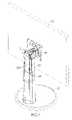
- FIG. 1is a perspective view of a flat panel display stand in accordance with the present invention
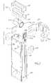
- FIG. 2is an enlarged exploded perspective view of a post, a resilient assembly and part of a holding bracket in the flat panel display stand in FIG. 1 ;
- FIG. 3is an enlarged rear cross sectional view of the post and resilient assembly of the flat panel display stand in FIG. 1 ;
- FIG. 4is an operational side view in partial section of the flat panel display stand in FIG. 1 ;
- FIG. 5is an operational side view in partial section of the flat panel display stand in FIG. 1 with the holding bracket near the top of the post.
- a flat panel display standin accordance with the present invention adjustably positions and holds a flat panel display ( 60 ) and comprises a base ( 10 ), a post ( 20 ), a resilient assembly ( 30 ), multiple fasteners ( 40 ) and a holding bracket ( 50 ).
- the base ( 10 )can be mounted on any plane.
- the post ( 20 )is connected securely to and protrudes perpendicularly from the base ( 10 ), may be telescopic and square tubular and has a top, a bottom, two sides, a channel ( 21 ), an inner surface, two guide slots ( 22 ), two optional hooks ( 23 ) and two optional braces ( 24 ).
- the channel ( 21 )is formed longitudinally inside the post ( 20 ) and may be rectangular in cross section.
- the inner surfaceis formed in the channel ( 21 ).
- the guide slots ( 22 )are formed respectively through the sides of the post ( 20 ) opposite to each other and communicate with the channel ( 21 ).
- the hooks ( 23 )protrude from the inner surface of the channel ( 21 ) near the top of the post ( 20 ).
- the braces ( 24 )may be “U” shaped, are mounted securely respectively across the top and the bottom of the post ( 20 ).
- the resilient assembly ( 30 )is mounted slidably in the channel ( 21 ) and has a driver ( 31 ), two friction feet ( 32 ), two mounting plates ( 33 ) and a coil spring ( 34 ).
- the driver ( 31 )is mounted slidably in the channel ( 21 ) between the guide slots ( 22 ) and has two ends, a bottom, multiple securing holes and a concave recess ( 310 ).
- the securing holesare formed in the ends of the driver ( 31 ).
- the concave recess ( 310 )may be semicircular, is formed transversely in the bottom of the driver ( 31 ).
- the friction feet ( 32 )are mounted in the channel ( 21 ) between the ends of the driver ( 31 ) and the sides of the post ( 20 ), and each friction foot ( 32 ) is flat and resilient and has a friction surface, multiple mounting holes, multiple ribs ( 322 ) and at least two blocks ( 321 ).
- the friction surfacescorrespond to and abut the inner surface of the post ( 20 ) adjacent respectively to the guide slots ( 22 ).
- the mounting holesare formed through the friction foot ( 32 ) and correspond respectively to the securing holes in the driver ( 31 ).
- the ribs ( 322 )are formed on the friction surface of the friction foot ( 32 ) and rub against the inner surface of the post ( 20 ) to provide friction that allows the supporting bracket to slide somewhat.
- the blocks ( 321 )are formed on and protrude from the friction surface of the friction foot ( 32 ) and mounted slidably respectively in the guide slots ( 22 ).
- the mounting plates ( 33 )are mounted outside the post ( 20 ) and correspond respectively to the friction feet ( 32 ), and each mounting plate ( 33 ) has multiple through holes corresponding respectively to the mounting holes in the corresponding friction foot ( 32 ).
- the coil spring ( 34 )has a mounting end, two optional notches ( 341 ) and a wound end.
- the mounting endis attached to the inner surface of the post ( 20 ) near the top.
- the notches ( 341 )are formed through the coil spring ( 34 ) adjacent to the mounting end and correspond to and hook respectively on the hooks ( 23 ) on the inner surface of the post ( 20 ).
- the wound endis mounted in the concave recess ( 310 ) of the driver ( 31 ), is unwound when the resilient assembly ( 30 ) moves down and provides a resilient force to hold the resilient assembly ( 30 ) in position.
- the fasteners ( 40 )extend through the fixing holes in the mounting plates ( 33 ) and the mounting holes in the friction feet ( 32 ) and are mounted in the securing holes in the driver ( 31 ) to attach the friction feet ( 32 ) to the driver ( 31 ) and makes the friction feet ( 32 ) and the mounting plates ( 33 ) rub against the post ( 20 ) adjacent to one of the guide slots ( 22 ) to generate friction to hold the resilient assembly ( 30 ) in position.
- the holding bracket ( 50 )is connected to a flat panel display ( 60 ) and has two wings ( 51 ) protruding backward.
- the wings ( 51 )have multiple through holes corresponding respectively to the fixing holes in the mounting plates ( 33 ) and are held in place by the fasteners ( 40 ).
- the flat panel display stand as describedis compact and provides adequate friction to hold the holding bracket ( 50 ) in position, and the wound end of the coil spring ( 34 ) is gradually extended to provide a balanced resilient force corresponding to the flat panel display ( 60 ) mounted on the holding bracket ( 50 ) to hold the resilient assembly ( 30 ) in position. Furthermore, the friction generated by the friction feet ( 32 ) allows adjustment of the flat panel display ( 60 ) with only a slight force.
Landscapes
- Engineering & Computer Science (AREA)
- General Engineering & Computer Science (AREA)
- Mechanical Engineering (AREA)
- Devices For Indicating Variable Information By Combining Individual Elements (AREA)
Abstract
Description
1. Field of the Invention
The present invention relates to a stand, and more particularly to a flat panel display stand that is compact in structure and facilitates adjustment of the position of a flat panel display mounted on the stand.
2. Description of Related Art
Flat panel displays have virtually replaced traditional cathode ray tube displays as standard equipment for personal computers because of the advantages of the flat panel displays like low radiation, small volume and light weigh. Generally, a flat panel display is mounted rotatably and movably on a flat panel display stand that allows the angle and possibly the height of the flat panel display to be adjusted.
Conventional flat panel display stands make using flat panel displays convenient, but improvements still need to be made to overcome disadvantages such as those that follow.
1. Many components of flat panel display stands protrude from the surface of the flat panel display stand and adversely affect the appearance of the flat panel display stand.
2. Adjusting the flat panel display stand is difficult, because friction to hold the flat panel display is usually excessive.
3. A large cover is required to cover all of the components of the flat panel display stand, which causes the flat panel display stand to have large volume and be troublesome to carry.
To overcome the shortcomings, the present invention provides a flat panel display stand to obviate or mitigate the aforementioned problems.
The main objective of the present invention is to provide a flat panel display stand that is compact and has adequate friction to hold a flat panel display in position.
The flat panel display stand in accordance with present invention comprises a base, a post, a resilient assembly and a holding bracket. The base can be mounted on any plane. The post is securely mounted perpendicularly on the base, has a channel defined inside the post and two guide slots formed through the post opposite to each other. The resilient assembly is mounted slidably in the channel and has two friction feet and a coil spring. The friction feet are mounted respectively in the guide slots of the post to guide the resilient assembly and generate adequate friction to hold the resilient assembly in position. The coil spring has an end secured in the channel and provides a resilient force to hold the resilient assembly in position. The holding bracket holds a flat panel display and is secured to the resilient assembly through the guide slots.
With such an arrangement, the flat panel display stand is compact and generates adequate friction to hold a flat panel display and allows the flat panel display to be adjusted easily.
Other objectives, advantages and novel features of the invention will become more apparent from the following detailed description when taken in conjunction with the accompanying drawings.
With reference toFIGS. 1 and 2 , a flat panel display stand in accordance with the present invention adjustably positions and holds a flat panel display (60) and comprises a base (10), a post (20), a resilient assembly (30), multiple fasteners (40) and a holding bracket (50).
The base (10) can be mounted on any plane.
The post (20) is connected securely to and protrudes perpendicularly from the base (10), may be telescopic and square tubular and has a top, a bottom, two sides, a channel (21), an inner surface, two guide slots (22), two optional hooks (23) and two optional braces (24).
The channel (21) is formed longitudinally inside the post (20) and may be rectangular in cross section.
The inner surface is formed in the channel (21).
The guide slots (22) are formed respectively through the sides of the post (20) opposite to each other and communicate with the channel (21).
The hooks (23) protrude from the inner surface of the channel (21) near the top of the post (20).
The braces (24) may be “U” shaped, are mounted securely respectively across the top and the bottom of the post (20).
The resilient assembly (30) is mounted slidably in the channel (21) and has a driver (31), two friction feet (32), two mounting plates (33) and a coil spring (34).
The driver (31) is mounted slidably in the channel (21) between the guide slots (22) and has two ends, a bottom, multiple securing holes and a concave recess (310). The securing holes are formed in the ends of the driver (31). The concave recess (310) may be semicircular, is formed transversely in the bottom of the driver (31).
The friction feet (32) are mounted in the channel (21) between the ends of the driver (31) and the sides of the post (20), and each friction foot (32) is flat and resilient and has a friction surface, multiple mounting holes, multiple ribs (322) and at least two blocks (321). The friction surfaces correspond to and abut the inner surface of the post (20) adjacent respectively to the guide slots (22). The mounting holes are formed through the friction foot (32) and correspond respectively to the securing holes in the driver (31). The ribs (322) are formed on the friction surface of the friction foot (32) and rub against the inner surface of the post (20) to provide friction that allows the supporting bracket to slide somewhat. The blocks (321) are formed on and protrude from the friction surface of the friction foot (32) and mounted slidably respectively in the guide slots (22).
The mounting plates (33) are mounted outside the post (20) and correspond respectively to the friction feet (32), and each mounting plate (33) has multiple through holes corresponding respectively to the mounting holes in the corresponding friction foot (32).
With further reference toFIGS. 2 ,3 and4, the coil spring (34) has a mounting end, two optional notches (341) and a wound end. The mounting end is attached to the inner surface of the post (20) near the top. The notches (341) are formed through the coil spring (34) adjacent to the mounting end and correspond to and hook respectively on the hooks (23) on the inner surface of the post (20). The wound end is mounted in the concave recess (310) of the driver (31), is unwound when the resilient assembly (30) moves down and provides a resilient force to hold the resilient assembly (30) in position.
The fasteners (40) extend through the fixing holes in the mounting plates (33) and the mounting holes in the friction feet (32) and are mounted in the securing holes in the driver (31) to attach the friction feet (32) to the driver (31) and makes the friction feet (32) and the mounting plates (33) rub against the post (20) adjacent to one of the guide slots (22) to generate friction to hold the resilient assembly (30) in position.
The holding bracket (50) is connected to a flat panel display (60) and has two wings (51) protruding backward. The wings (51) have multiple through holes corresponding respectively to the fixing holes in the mounting plates (33) and are held in place by the fasteners (40).
With further reference toFIGS. 4 and 5 , the flat panel display stand as described is compact and provides adequate friction to hold the holding bracket (50) in position, and the wound end of the coil spring (34) is gradually extended to provide a balanced resilient force corresponding to the flat panel display (60) mounted on the holding bracket (50) to hold the resilient assembly (30) in position. Furthermore, the friction generated by the friction feet (32) allows adjustment of the flat panel display (60) with only a slight force.
Even though numerous characteristics and advantages of the present invention have been set forth in the foregoing description together with details of the structure and function of the invention, the disclosure is illustrative only. Changes may be made in detail especially in matters of shape, size and arrangement of parts within the principles of the invention to the full extent indicated by the broad general meaning of the terms in which the appended claims are expressed.
Claims (5)
1. A flat panel display stand comprising
a base;
a post being connected securely to and protruding perpendicularly from the base and having
a top;
a bottom;
two sides;
a channel being formed longitudinally inside the post;
an inner surface being formed in the channel; and
two guide slots being formed respectively through the sides of the post opposite to each other and communicating with the channel;
a resilient assembly being mounted slidably in the channel and having
a driver being mounted movably in the channel and having
two ends;
a bottom;
multiple securing holes being formed in the ends of the driver; and
a concave recess being formed transversely in the bottom of the driver;
two friction feet being mounted in the channel between the ends of the driver and the sides of the post, and each friction foot being flat and resilient and having
a friction surface corresponding to and abutting the inner surface of the post adjacent to one of the guide slots;
multiple mounting holes being formed through the friction foot and corresponding respectively to the securing holes in the driver;
multiple ribs being formed on the friction surface of the friction foot and rubbing against the inner surface of the post; and
at least two blocks being formed on and protruding from the friction surface of the friction foot and mounted slidably respectively in the corresponding guide slot;
two mounting plates being mounted outside the post and corresponding respectively to the friction feet outside the post, and each mounting plate having multiple through holes corresponding respectively to the mounting holes in the corresponding friction foot; and
a coil spring having
a mounting end secured on the inner surface of the post near the top; and
a wound end being mounted in the concave recess of the driver, being unwound when the resilient assembly moves down and providing a resilient force to hold the resilient assembly in position;
multiple fasteners extending through the fixing holes in the mounting plates and the mounting holes in the friction feet and being secured in the securing holes in the driver to attach the friction feet to the driver and making the friction feet and the mounting plates rub against the inner surface of the post adjacent to one of the guide slots to generate friction to hold the resilient assembly in position; and
a holding bracket being adapted for being connected to a flat panel display and having two wings protruding backward and having multiple through holes corresponding respectively to the fixing holes in the mounting plates and being held in place by the fasteners.
2. The flat panel display stand as claimed inclaim 1 , wherein
the post further has two hooks protruding from the inner surface of the channel near the top of the post; and
the coil spring further has two notches being formed through the coil spring adjacent to the mounting end and corresponding to and hooking respectively on the hooks on the inner surface of the post.
3. The flat panel display stand as claimed inclaim 1 , wherein the post further has two braces being mounted securely respectively across the top and the bottom of the post.
4. The flat panel display stand as claimed inclaim 1 , wherein the channel of the post is rectangular in cross section.
5. The flat panel display stand as claimed inclaim 1 , wherein the concave recess of the driver is semicircular.
Priority Applications (1)
| Application Number | Priority Date | Filing Date | Title |
|---|---|---|---|
| US11/764,935US7413150B1 (en) | 2007-06-19 | 2007-06-19 | Flat panel display stand |
Applications Claiming Priority (1)
| Application Number | Priority Date | Filing Date | Title |
|---|---|---|---|
| US11/764,935US7413150B1 (en) | 2007-06-19 | 2007-06-19 | Flat panel display stand |
Publications (1)
| Publication Number | Publication Date |
|---|---|
| US7413150B1true US7413150B1 (en) | 2008-08-19 |
Family
ID=39687188
Family Applications (1)
| Application Number | Title | Priority Date | Filing Date |
|---|---|---|---|
| US11/764,935Expired - Fee RelatedUS7413150B1 (en) | 2007-06-19 | 2007-06-19 | Flat panel display stand |
Country Status (1)
| Country | Link |
|---|---|
| US (1) | US7413150B1 (en) |
Cited By (65)
| Publication number | Priority date | Publication date | Assignee | Title |
|---|---|---|---|---|
| US20050258334A1 (en)* | 2004-05-04 | 2005-11-24 | Hwang Kwang-Sung | Display apparatus |
| US20070194182A1 (en)* | 2006-02-17 | 2007-08-23 | Lg Electronics Inc. | Stand for display device |
| US20080164398A1 (en)* | 2007-01-08 | 2008-07-10 | Samsung Electro-Mechanics Co., Ltd. | Display support apparatus |
| USD588141S1 (en)* | 2008-03-27 | 2009-03-10 | Dell Products L.P. | Flat panel monitor docking station stand |
| USD588602S1 (en)* | 2007-11-27 | 2009-03-17 | Coretronic Corporation | Stand for monitor |
| US20100001148A1 (en)* | 2008-07-01 | 2010-01-07 | Dell Products, Lp | Flat Panel Monitor Assembly with Weight Adjust Mechanism |
| US20100006716A1 (en)* | 2008-07-14 | 2010-01-14 | Ching-Hui Yen | Support frame for a variety kinds of display devices |
| US20100157564A1 (en)* | 2008-12-23 | 2010-06-24 | Hong Fu Jin Precision Industry (Shenzhen) Co., Ltd. | Adjustment module |
| US20100283193A1 (en)* | 2008-08-05 | 2010-11-11 | Chia Hao Huang | Clamp of Anti-Vibration Spring |
| US20100320339A1 (en)* | 2009-06-17 | 2010-12-23 | Hong Fu Jin Precision Industry (Shenzhen) Co., Ltd. | Height adjustable stand and flat panel display utilizing the same |
| US20110068243A1 (en)* | 2009-09-24 | 2011-03-24 | Hong Fu Jin Precision Industry (Shenzhen) Co., Ltd. | Adjustable apparatus |
| USD638022S1 (en)* | 2010-03-24 | 2011-05-17 | Nec Display Solutions, Ltd. | Display |
| USD653245S1 (en)* | 2010-03-21 | 2012-01-31 | Cisco Technology, Inc. | Video unit with integrated features |
| USD655279S1 (en)* | 2010-03-21 | 2012-03-06 | Cisco Technology, Inc. | Video unit with integrated features |
| US20120224303A1 (en)* | 2011-03-02 | 2012-09-06 | Kunshan Eson Precision Engineering Co., Ltd. | Support and display device using the same |
| US8319819B2 (en) | 2008-03-26 | 2012-11-27 | Cisco Technology, Inc. | Virtual round-table videoconference |
| US8355041B2 (en) | 2008-02-14 | 2013-01-15 | Cisco Technology, Inc. | Telepresence system for 360 degree video conferencing |
| US8390667B2 (en) | 2008-04-15 | 2013-03-05 | Cisco Technology, Inc. | Pop-up PIP for people not in picture |
| USD678308S1 (en) | 2010-12-16 | 2013-03-19 | Cisco Technology, Inc. | Display screen with graphical user interface |
| USD678320S1 (en) | 2010-12-16 | 2013-03-19 | Cisco Technology, Inc. | Display screen with graphical user interface |
| USD678307S1 (en) | 2010-12-16 | 2013-03-19 | Cisco Technology, Inc. | Display screen with graphical user interface |
| USD678894S1 (en) | 2010-12-16 | 2013-03-26 | Cisco Technology, Inc. | Display screen with graphical user interface |
| US20130075546A1 (en)* | 2011-09-23 | 2013-03-28 | Syncmold Enterprise Corp. | Monitor stand |
| USD681647S1 (en)* | 2012-01-17 | 2013-05-07 | Samsung Electronics Co., Ltd. | Stand for a monitor |
| USD682294S1 (en) | 2010-12-16 | 2013-05-14 | Cisco Technology, Inc. | Display screen with graphical user interface |
| USD682293S1 (en) | 2010-12-16 | 2013-05-14 | Cisco Technology, Inc. | Display screen with graphical user interface |
| USD682854S1 (en) | 2010-12-16 | 2013-05-21 | Cisco Technology, Inc. | Display screen for graphical user interface |
| USD682864S1 (en) | 2010-12-16 | 2013-05-21 | Cisco Technology, Inc. | Display screen with graphical user interface |
| US8472415B2 (en) | 2006-03-06 | 2013-06-25 | Cisco Technology, Inc. | Performance optimization with integrated mobility and MPLS |
| US8477175B2 (en) | 2009-03-09 | 2013-07-02 | Cisco Technology, Inc. | System and method for providing three dimensional imaging in a network environment |
| US8542264B2 (en) | 2010-11-18 | 2013-09-24 | Cisco Technology, Inc. | System and method for managing optics in a video environment |
| US8599934B2 (en) | 2010-09-08 | 2013-12-03 | Cisco Technology, Inc. | System and method for skip coding during video conferencing in a network environment |
| US8599865B2 (en) | 2010-10-26 | 2013-12-03 | Cisco Technology, Inc. | System and method for provisioning flows in a mobile network environment |
| US8659637B2 (en) | 2009-03-09 | 2014-02-25 | Cisco Technology, Inc. | System and method for providing three dimensional video conferencing in a network environment |
| US8659639B2 (en) | 2009-05-29 | 2014-02-25 | Cisco Technology, Inc. | System and method for extending communications between participants in a conferencing environment |
| US8670019B2 (en) | 2011-04-28 | 2014-03-11 | Cisco Technology, Inc. | System and method for providing enhanced eye gaze in a video conferencing environment |
| US8682087B2 (en) | 2011-12-19 | 2014-03-25 | Cisco Technology, Inc. | System and method for depth-guided image filtering in a video conference environment |
| US8692862B2 (en) | 2011-02-28 | 2014-04-08 | Cisco Technology, Inc. | System and method for selection of video data in a video conference environment |
| US8694658B2 (en) | 2008-09-19 | 2014-04-08 | Cisco Technology, Inc. | System and method for enabling communication sessions in a network environment |
| US8699457B2 (en) | 2010-11-03 | 2014-04-15 | Cisco Technology, Inc. | System and method for managing flows in a mobile network environment |
| US8723914B2 (en) | 2010-11-19 | 2014-05-13 | Cisco Technology, Inc. | System and method for providing enhanced video processing in a network environment |
| US8730297B2 (en) | 2010-11-15 | 2014-05-20 | Cisco Technology, Inc. | System and method for providing camera functions in a video environment |
| US8786631B1 (en) | 2011-04-30 | 2014-07-22 | Cisco Technology, Inc. | System and method for transferring transparency information in a video environment |
| US8797377B2 (en) | 2008-02-14 | 2014-08-05 | Cisco Technology, Inc. | Method and system for videoconference configuration |
| US20140284435A1 (en)* | 2011-09-23 | 2014-09-25 | Der-Wei Lu | Monitor stand |
| US8896655B2 (en) | 2010-08-31 | 2014-11-25 | Cisco Technology, Inc. | System and method for providing depth adaptive video conferencing |
| US8902244B2 (en) | 2010-11-15 | 2014-12-02 | Cisco Technology, Inc. | System and method for providing enhanced graphics in a video environment |
| US8934026B2 (en) | 2011-05-12 | 2015-01-13 | Cisco Technology, Inc. | System and method for video coding in a dynamic environment |
| US8947493B2 (en) | 2011-11-16 | 2015-02-03 | Cisco Technology, Inc. | System and method for alerting a participant in a video conference |
| US9082297B2 (en) | 2009-08-11 | 2015-07-14 | Cisco Technology, Inc. | System and method for verifying parameters in an audiovisual environment |
| US9111138B2 (en) | 2010-11-30 | 2015-08-18 | Cisco Technology, Inc. | System and method for gesture interface control |
| US9143725B2 (en) | 2010-11-15 | 2015-09-22 | Cisco Technology, Inc. | System and method for providing enhanced graphics in a video environment |
| US9225916B2 (en) | 2010-03-18 | 2015-12-29 | Cisco Technology, Inc. | System and method for enhancing video images in a conferencing environment |
| US9279537B2 (en)* | 2014-06-06 | 2016-03-08 | Modernsolid Industrial Co., Ltd. | Supporting apparatus for supporting a display |
| US20160091135A1 (en)* | 2014-09-29 | 2016-03-31 | Wistron Corporation | Positionable lift stand |
| US9313452B2 (en) | 2010-05-17 | 2016-04-12 | Cisco Technology, Inc. | System and method for providing retracting optics in a video conferencing environment |
| US9338394B2 (en) | 2010-11-15 | 2016-05-10 | Cisco Technology, Inc. | System and method for providing enhanced audio in a video environment |
| US9681154B2 (en) | 2012-12-06 | 2017-06-13 | Patent Capital Group | System and method for depth-guided filtering in a video conference environment |
| US9702501B2 (en)* | 2015-12-01 | 2017-07-11 | Oxti Corporation | Support device for monitor or display |
| US20170219158A1 (en)* | 2016-02-03 | 2017-08-03 | Syncmold Enterprise Corp. | Elevatable supporting device |
| US9843621B2 (en) | 2013-05-17 | 2017-12-12 | Cisco Technology, Inc. | Calendaring activities based on communication processing |
| US20180112816A1 (en)* | 2016-10-21 | 2018-04-26 | Jarllytec Co., Ltd. | Lift mechanism and thin-type supporting device utilizing the same |
| US20190120422A1 (en)* | 2017-10-23 | 2019-04-25 | Qingdao Hisense Laser Display Co., Ltd. | Wall-hung bracket for projection screen |
| US11608930B2 (en)* | 2021-01-19 | 2023-03-21 | Syncmold Enterprise Corp. | Supporting stand |
| USD985576S1 (en) | 2021-05-19 | 2023-05-09 | Paul Harris | Adjustable monitor stand |
Citations (11)
| Publication number | Priority date | Publication date | Assignee | Title |
|---|---|---|---|---|
| US6189849B1 (en)* | 1998-05-06 | 2001-02-20 | Ergotron, Inc. | Lift system |
| US6712321B1 (en)* | 2003-05-21 | 2004-03-30 | Compal Electronics, Inc. | Adjustable supporting device for a display panel |
| US20040118984A1 (en)* | 2002-09-27 | 2004-06-24 | Samsung Electronics Co., Ltd. | Display apparatus |
| US6874743B2 (en)* | 2001-12-13 | 2005-04-05 | Murakami Corporation | Direction regulator of display |
| US6874738B2 (en)* | 2001-12-13 | 2005-04-05 | Murakami Corporation | Elevation regulator of display |
| US6918564B2 (en)* | 2002-06-25 | 2005-07-19 | Benq Corporation | Height adjustable apparatus for supporting flat monitor |
| US20060038092A1 (en)* | 2004-08-18 | 2006-02-23 | Choi Hyun-Yong | Monitor |
| US7036787B1 (en)* | 2005-02-04 | 2006-05-02 | Taiwan Thick-Film Ind. Corp. | Display strut adjusting structure |
| US20060118680A1 (en)* | 2004-12-07 | 2006-06-08 | Benq Corporation | Display stand |
| US20060219849A1 (en)* | 2005-04-04 | 2006-10-05 | Fulfil Tech. Co., Ltd. | Height-adjustable support for a display device |
| US7274555B2 (en)* | 2002-11-11 | 2007-09-25 | Samsung Electronics Co., Ltd. | Stand for supporting a monitor main body |
- 2007
- 2007-06-19USUS11/764,935patent/US7413150B1/ennot_activeExpired - Fee Related
Patent Citations (11)
| Publication number | Priority date | Publication date | Assignee | Title |
|---|---|---|---|---|
| US6189849B1 (en)* | 1998-05-06 | 2001-02-20 | Ergotron, Inc. | Lift system |
| US6874743B2 (en)* | 2001-12-13 | 2005-04-05 | Murakami Corporation | Direction regulator of display |
| US6874738B2 (en)* | 2001-12-13 | 2005-04-05 | Murakami Corporation | Elevation regulator of display |
| US6918564B2 (en)* | 2002-06-25 | 2005-07-19 | Benq Corporation | Height adjustable apparatus for supporting flat monitor |
| US20040118984A1 (en)* | 2002-09-27 | 2004-06-24 | Samsung Electronics Co., Ltd. | Display apparatus |
| US7274555B2 (en)* | 2002-11-11 | 2007-09-25 | Samsung Electronics Co., Ltd. | Stand for supporting a monitor main body |
| US6712321B1 (en)* | 2003-05-21 | 2004-03-30 | Compal Electronics, Inc. | Adjustable supporting device for a display panel |
| US20060038092A1 (en)* | 2004-08-18 | 2006-02-23 | Choi Hyun-Yong | Monitor |
| US20060118680A1 (en)* | 2004-12-07 | 2006-06-08 | Benq Corporation | Display stand |
| US7036787B1 (en)* | 2005-02-04 | 2006-05-02 | Taiwan Thick-Film Ind. Corp. | Display strut adjusting structure |
| US20060219849A1 (en)* | 2005-04-04 | 2006-10-05 | Fulfil Tech. Co., Ltd. | Height-adjustable support for a display device |
Cited By (81)
| Publication number | Priority date | Publication date | Assignee | Title |
|---|---|---|---|---|
| US8047487B2 (en)* | 2004-05-04 | 2011-11-01 | Samsung Electronics Co., Ltd. | Display apparatus having adjustable supporting unit |
| US20050258334A1 (en)* | 2004-05-04 | 2005-11-24 | Hwang Kwang-Sung | Display apparatus |
| US7694919B2 (en)* | 2006-02-17 | 2010-04-13 | Lg Electronics Inc. | Stand for display device |
| US20070194182A1 (en)* | 2006-02-17 | 2007-08-23 | Lg Electronics Inc. | Stand for display device |
| US8472415B2 (en) | 2006-03-06 | 2013-06-25 | Cisco Technology, Inc. | Performance optimization with integrated mobility and MPLS |
| US20080164398A1 (en)* | 2007-01-08 | 2008-07-10 | Samsung Electro-Mechanics Co., Ltd. | Display support apparatus |
| USD588602S1 (en)* | 2007-11-27 | 2009-03-17 | Coretronic Corporation | Stand for monitor |
| US8797377B2 (en) | 2008-02-14 | 2014-08-05 | Cisco Technology, Inc. | Method and system for videoconference configuration |
| US8355041B2 (en) | 2008-02-14 | 2013-01-15 | Cisco Technology, Inc. | Telepresence system for 360 degree video conferencing |
| US8319819B2 (en) | 2008-03-26 | 2012-11-27 | Cisco Technology, Inc. | Virtual round-table videoconference |
| USD588141S1 (en)* | 2008-03-27 | 2009-03-10 | Dell Products L.P. | Flat panel monitor docking station stand |
| US8390667B2 (en) | 2008-04-15 | 2013-03-05 | Cisco Technology, Inc. | Pop-up PIP for people not in picture |
| US20100001148A1 (en)* | 2008-07-01 | 2010-01-07 | Dell Products, Lp | Flat Panel Monitor Assembly with Weight Adjust Mechanism |
| US7883063B2 (en)* | 2008-07-01 | 2011-02-08 | Dell Products, Lp | Flat panel monitor assembly with weight adjust mechanism |
| US20100006716A1 (en)* | 2008-07-14 | 2010-01-14 | Ching-Hui Yen | Support frame for a variety kinds of display devices |
| US7780125B2 (en)* | 2008-07-14 | 2010-08-24 | Syncmold Enterprise Corp. | Support frame for a variety kinds of display devices |
| US20100283193A1 (en)* | 2008-08-05 | 2010-11-11 | Chia Hao Huang | Clamp of Anti-Vibration Spring |
| US8112856B2 (en)* | 2008-08-05 | 2012-02-14 | Yakita Metal Industry Co., Ltd. | Clamp of anti-vibration spring |
| US8694658B2 (en) | 2008-09-19 | 2014-04-08 | Cisco Technology, Inc. | System and method for enabling communication sessions in a network environment |
| US8111507B2 (en)* | 2008-12-23 | 2012-02-07 | Hong Fu Jin Precision Industry (Shenzhen) Co., Ltd. | Adjustment module |
| US20100157564A1 (en)* | 2008-12-23 | 2010-06-24 | Hong Fu Jin Precision Industry (Shenzhen) Co., Ltd. | Adjustment module |
| US8477175B2 (en) | 2009-03-09 | 2013-07-02 | Cisco Technology, Inc. | System and method for providing three dimensional imaging in a network environment |
| US8659637B2 (en) | 2009-03-09 | 2014-02-25 | Cisco Technology, Inc. | System and method for providing three dimensional video conferencing in a network environment |
| US9204096B2 (en) | 2009-05-29 | 2015-12-01 | Cisco Technology, Inc. | System and method for extending communications between participants in a conferencing environment |
| US8659639B2 (en) | 2009-05-29 | 2014-02-25 | Cisco Technology, Inc. | System and method for extending communications between participants in a conferencing environment |
| US8201782B2 (en)* | 2009-06-17 | 2012-06-19 | Hong Fu Jin Precision Industry (Shenzhen) Co., Ltd. | Height adjustable stand and flat panel display utilizing the same |
| US20100320339A1 (en)* | 2009-06-17 | 2010-12-23 | Hong Fu Jin Precision Industry (Shenzhen) Co., Ltd. | Height adjustable stand and flat panel display utilizing the same |
| US9082297B2 (en) | 2009-08-11 | 2015-07-14 | Cisco Technology, Inc. | System and method for verifying parameters in an audiovisual environment |
| US20110068243A1 (en)* | 2009-09-24 | 2011-03-24 | Hong Fu Jin Precision Industry (Shenzhen) Co., Ltd. | Adjustable apparatus |
| US8074948B2 (en)* | 2009-09-24 | 2011-12-13 | Hong Fu Jin Precision Industry (Shenzhen) Co., Ltd. | Adjustable apparatus |
| US9225916B2 (en) | 2010-03-18 | 2015-12-29 | Cisco Technology, Inc. | System and method for enhancing video images in a conferencing environment |
| USD655279S1 (en)* | 2010-03-21 | 2012-03-06 | Cisco Technology, Inc. | Video unit with integrated features |
| USD653245S1 (en)* | 2010-03-21 | 2012-01-31 | Cisco Technology, Inc. | Video unit with integrated features |
| USD638022S1 (en)* | 2010-03-24 | 2011-05-17 | Nec Display Solutions, Ltd. | Display |
| US9313452B2 (en) | 2010-05-17 | 2016-04-12 | Cisco Technology, Inc. | System and method for providing retracting optics in a video conferencing environment |
| US8896655B2 (en) | 2010-08-31 | 2014-11-25 | Cisco Technology, Inc. | System and method for providing depth adaptive video conferencing |
| US8599934B2 (en) | 2010-09-08 | 2013-12-03 | Cisco Technology, Inc. | System and method for skip coding during video conferencing in a network environment |
| US8599865B2 (en) | 2010-10-26 | 2013-12-03 | Cisco Technology, Inc. | System and method for provisioning flows in a mobile network environment |
| US9331948B2 (en) | 2010-10-26 | 2016-05-03 | Cisco Technology, Inc. | System and method for provisioning flows in a mobile network environment |
| US8699457B2 (en) | 2010-11-03 | 2014-04-15 | Cisco Technology, Inc. | System and method for managing flows in a mobile network environment |
| US9338394B2 (en) | 2010-11-15 | 2016-05-10 | Cisco Technology, Inc. | System and method for providing enhanced audio in a video environment |
| US9143725B2 (en) | 2010-11-15 | 2015-09-22 | Cisco Technology, Inc. | System and method for providing enhanced graphics in a video environment |
| US8902244B2 (en) | 2010-11-15 | 2014-12-02 | Cisco Technology, Inc. | System and method for providing enhanced graphics in a video environment |
| US8730297B2 (en) | 2010-11-15 | 2014-05-20 | Cisco Technology, Inc. | System and method for providing camera functions in a video environment |
| US8542264B2 (en) | 2010-11-18 | 2013-09-24 | Cisco Technology, Inc. | System and method for managing optics in a video environment |
| US8723914B2 (en) | 2010-11-19 | 2014-05-13 | Cisco Technology, Inc. | System and method for providing enhanced video processing in a network environment |
| US9111138B2 (en) | 2010-11-30 | 2015-08-18 | Cisco Technology, Inc. | System and method for gesture interface control |
| USD682294S1 (en) | 2010-12-16 | 2013-05-14 | Cisco Technology, Inc. | Display screen with graphical user interface |
| USD682854S1 (en) | 2010-12-16 | 2013-05-21 | Cisco Technology, Inc. | Display screen for graphical user interface |
| USD678307S1 (en) | 2010-12-16 | 2013-03-19 | Cisco Technology, Inc. | Display screen with graphical user interface |
| USD678320S1 (en) | 2010-12-16 | 2013-03-19 | Cisco Technology, Inc. | Display screen with graphical user interface |
| USD678308S1 (en) | 2010-12-16 | 2013-03-19 | Cisco Technology, Inc. | Display screen with graphical user interface |
| USD678894S1 (en) | 2010-12-16 | 2013-03-26 | Cisco Technology, Inc. | Display screen with graphical user interface |
| USD682864S1 (en) | 2010-12-16 | 2013-05-21 | Cisco Technology, Inc. | Display screen with graphical user interface |
| USD682293S1 (en) | 2010-12-16 | 2013-05-14 | Cisco Technology, Inc. | Display screen with graphical user interface |
| US8692862B2 (en) | 2011-02-28 | 2014-04-08 | Cisco Technology, Inc. | System and method for selection of video data in a video conference environment |
| US20120224303A1 (en)* | 2011-03-02 | 2012-09-06 | Kunshan Eson Precision Engineering Co., Ltd. | Support and display device using the same |
| US8625259B2 (en)* | 2011-03-02 | 2014-01-07 | Kunshan Eson Precision Engineering Co., Ltd. | Support and display device using the same |
| US8670019B2 (en) | 2011-04-28 | 2014-03-11 | Cisco Technology, Inc. | System and method for providing enhanced eye gaze in a video conferencing environment |
| US8786631B1 (en) | 2011-04-30 | 2014-07-22 | Cisco Technology, Inc. | System and method for transferring transparency information in a video environment |
| US8934026B2 (en) | 2011-05-12 | 2015-01-13 | Cisco Technology, Inc. | System and method for video coding in a dynamic environment |
| US20140284435A1 (en)* | 2011-09-23 | 2014-09-25 | Der-Wei Lu | Monitor stand |
| US20130075546A1 (en)* | 2011-09-23 | 2013-03-28 | Syncmold Enterprise Corp. | Monitor stand |
| US9046216B2 (en)* | 2011-09-23 | 2015-06-02 | Syncmold Enterprise Corp. | Monitor stand |
| US8947493B2 (en) | 2011-11-16 | 2015-02-03 | Cisco Technology, Inc. | System and method for alerting a participant in a video conference |
| US8682087B2 (en) | 2011-12-19 | 2014-03-25 | Cisco Technology, Inc. | System and method for depth-guided image filtering in a video conference environment |
| USD681647S1 (en)* | 2012-01-17 | 2013-05-07 | Samsung Electronics Co., Ltd. | Stand for a monitor |
| US9681154B2 (en) | 2012-12-06 | 2017-06-13 | Patent Capital Group | System and method for depth-guided filtering in a video conference environment |
| US9843621B2 (en) | 2013-05-17 | 2017-12-12 | Cisco Technology, Inc. | Calendaring activities based on communication processing |
| US9279537B2 (en)* | 2014-06-06 | 2016-03-08 | Modernsolid Industrial Co., Ltd. | Supporting apparatus for supporting a display |
| US20160091135A1 (en)* | 2014-09-29 | 2016-03-31 | Wistron Corporation | Positionable lift stand |
| US9915394B2 (en)* | 2014-09-29 | 2018-03-13 | Wistron Corporation | Positionable lift stand |
| US9702501B2 (en)* | 2015-12-01 | 2017-07-11 | Oxti Corporation | Support device for monitor or display |
| US20170219158A1 (en)* | 2016-02-03 | 2017-08-03 | Syncmold Enterprise Corp. | Elevatable supporting device |
| US9976691B2 (en)* | 2016-02-03 | 2018-05-22 | Syncmold Enterprise Corp. | Elevatable supporting device |
| US20180112816A1 (en)* | 2016-10-21 | 2018-04-26 | Jarllytec Co., Ltd. | Lift mechanism and thin-type supporting device utilizing the same |
| US10428999B2 (en)* | 2016-10-21 | 2019-10-01 | Jarllytec Co., Ltd. | Lift mechanism and thin-type supporting device utilizing the same |
| US20190120422A1 (en)* | 2017-10-23 | 2019-04-25 | Qingdao Hisense Laser Display Co., Ltd. | Wall-hung bracket for projection screen |
| US10436381B2 (en)* | 2017-10-23 | 2019-10-08 | Qingdao Hisense Laser Display Co., Ltd. | Wall-hung bracket for projection screen |
| US11608930B2 (en)* | 2021-01-19 | 2023-03-21 | Syncmold Enterprise Corp. | Supporting stand |
| USD985576S1 (en) | 2021-05-19 | 2023-05-09 | Paul Harris | Adjustable monitor stand |
Similar Documents
| Publication | Publication Date | Title |
|---|---|---|
| US7413150B1 (en) | Flat panel display stand | |
| US8047480B2 (en) | Flat panel display having height adjusting member | |
| US7975970B2 (en) | Flat panel display support | |
| US7011285B2 (en) | Modular stand structure | |
| US10544927B2 (en) | Clamp lamp and displaying device therewith | |
| US11531374B2 (en) | Attachable display screen for electronic devices | |
| US6437975B1 (en) | LCD Screen | |
| US20110155868A1 (en) | Bracket for screen expansion, display, and display assembly | |
| US8023283B2 (en) | Portable electronic device | |
| US7753336B2 (en) | Adjustable extending stand for panel displays | |
| US7667957B2 (en) | Thin-type display | |
| US7150440B2 (en) | Adjustable support frame for a display screen | |
| US8387937B2 (en) | Stand | |
| US20100065702A1 (en) | Flat panel display support | |
| US20100284137A1 (en) | Television with folding stand | |
| US7986512B2 (en) | Electronic device frame with support mechanism | |
| US20060231699A1 (en) | Supporting structure for display panel | |
| US20120224317A1 (en) | Point-of-sale system bracket and a point-of-sale system | |
| US20050189457A1 (en) | Adjustable garment rod | |
| US8253878B2 (en) | Adjustable support apparatus for an LCD monitor | |
| CN102346513A (en) | Computer case | |
| US20120318943A1 (en) | Hanging module | |
| CN110107790B (en) | Wall hanging device and display | |
| EP1696169A2 (en) | Adjustable support frame for a display screen | |
| US20140123511A1 (en) | Height measuring device for cavity |
Legal Events
| Date | Code | Title | Description |
|---|---|---|---|
| AS | Assignment | Owner name:SHIN ZU SHING CO., LTD., TAIWAN Free format text:ASSIGNMENT OF ASSIGNORS INTEREST;ASSIGNOR:HSU, CHUN-CHING;REEL/FRAME:019447/0708 Effective date:20070615 | |
| STCF | Information on status: patent grant | Free format text:PATENTED CASE | |
| FPAY | Fee payment | Year of fee payment:4 | |
| FPAY | Fee payment | Year of fee payment:8 | |
| FEPP | Fee payment procedure | Free format text:MAINTENANCE FEE REMINDER MAILED (ORIGINAL EVENT CODE: REM.); ENTITY STATUS OF PATENT OWNER: LARGE ENTITY | |
| LAPS | Lapse for failure to pay maintenance fees | Free format text:PATENT EXPIRED FOR FAILURE TO PAY MAINTENANCE FEES (ORIGINAL EVENT CODE: EXP.); ENTITY STATUS OF PATENT OWNER: LARGE ENTITY | |
| STCH | Information on status: patent discontinuation | Free format text:PATENT EXPIRED DUE TO NONPAYMENT OF MAINTENANCE FEES UNDER 37 CFR 1.362 | |
| FP | Lapsed due to failure to pay maintenance fee | Effective date:20200819 |