US7412141B2 - Light diffusing tip - Google Patents
Light diffusing tipDownload PDFInfo
- Publication number
- US7412141B2 US7412141B2US11/777,856US77785607AUS7412141B2US 7412141 B2US7412141 B2US 7412141B2US 77785607 AUS77785607 AUS 77785607AUS 7412141 B2US7412141 B2US 7412141B2
- Authority
- US
- United States
- Prior art keywords
- scattering
- housing
- light
- region
- scattering material
- Prior art date
- Legal status (The legal status is an assumption and is not a legal conclusion. Google has not performed a legal analysis and makes no representation as to the accuracy of the status listed.)
- Expired - Lifetime
Links
- 230000003287optical effectEffects0.000claimsabstractdescription29
- 238000000149argon plasma sinteringMethods0.000claimsabstractdescription10
- 239000000463materialSubstances0.000claimsdescription151
- 238000000034methodMethods0.000claimsdescription43
- 239000002245particleSubstances0.000claimsdescription41
- 238000002156mixingMethods0.000claimsdescription7
- 206010028980NeoplasmDiseases0.000claimsdescription5
- 238000002428photodynamic therapyMethods0.000claimsdescription5
- 229920000642polymerPolymers0.000claims2
- 239000000835fiberSubstances0.000description23
- 239000011162core materialSubstances0.000description21
- 210000001519tissueAnatomy0.000description17
- GWEVSGVZZGPLCZ-UHFFFAOYSA-NTitan oxideChemical compoundO=[Ti]=OGWEVSGVZZGPLCZ-UHFFFAOYSA-N0.000description12
- 239000013307optical fiberSubstances0.000description10
- 238000005253claddingMethods0.000description7
- 230000007423decreaseEffects0.000description7
- 229920001971elastomerPolymers0.000description7
- 239000000806elastomerSubstances0.000description7
- 238000007796conventional methodMethods0.000description5
- 238000004519manufacturing processMethods0.000description5
- 210000000056organAnatomy0.000description5
- 229920001296polysiloxanePolymers0.000description5
- 239000004593EpoxySubstances0.000description4
- 239000011248coating agentSubstances0.000description4
- 238000000576coating methodMethods0.000description4
- 238000009826distributionMethods0.000description4
- 239000004033plasticSubstances0.000description4
- 229920003023plasticPolymers0.000description4
- 230000001681protective effectEffects0.000description4
- 239000004408titanium dioxideSubstances0.000description4
- 238000011282treatmentMethods0.000description4
- 235000013405beerNutrition0.000description3
- 230000007547defectEffects0.000description3
- 238000009792diffusion processMethods0.000description3
- 230000003902lesionEffects0.000description3
- 230000008569processEffects0.000description3
- PXHVJJICTQNCMI-UHFFFAOYSA-NNickelChemical compound[Ni]PXHVJJICTQNCMI-UHFFFAOYSA-N0.000description2
- 230000008901benefitEffects0.000description2
- 230000015572biosynthetic processEffects0.000description2
- 210000004556brainAnatomy0.000description2
- 230000015556catabolic processEffects0.000description2
- 230000008859changeEffects0.000description2
- 239000013065commercial productSubstances0.000description2
- 238000006731degradation reactionMethods0.000description2
- 239000004811fluoropolymerSubstances0.000description2
- 229920002313fluoropolymerPolymers0.000description2
- PCHJSUWPFVWCPO-UHFFFAOYSA-NgoldChemical compound[Au]PCHJSUWPFVWCPO-UHFFFAOYSA-N0.000description2
- 229910052737goldInorganic materials0.000description2
- 239000010931goldSubstances0.000description2
- 210000004185liverAnatomy0.000description2
- 229910052751metalInorganic materials0.000description2
- 239000002184metalSubstances0.000description2
- 239000000203mixtureSubstances0.000description2
- -1polyethylenePolymers0.000description2
- 230000005855radiationEffects0.000description2
- 239000007787solidSubstances0.000description2
- 238000002560therapeutic procedureMethods0.000description2
- VYZAMTAEIAYCRO-UHFFFAOYSA-NChromiumChemical compound[Cr]VYZAMTAEIAYCRO-UHFFFAOYSA-N0.000description1
- 229920001651CyanoacrylatePolymers0.000description1
- 239000004812Fluorinated ethylene propyleneSubstances0.000description1
- 239000004677NylonSubstances0.000description1
- 239000004696Poly ether ether ketoneSubstances0.000description1
- 239000004695Polyether sulfoneSubstances0.000description1
- 239000004698PolyethyleneSubstances0.000description1
- 239000004743PolypropyleneSubstances0.000description1
- 206010036940Prostatic adenomaDiseases0.000description1
- VYPSYNLAJGMNEJ-UHFFFAOYSA-NSilicium dioxideChemical compoundO=[Si]=OVYPSYNLAJGMNEJ-UHFFFAOYSA-N0.000description1
- BQCADISMDOOEFD-UHFFFAOYSA-NSilverChemical compound[Ag]BQCADISMDOOEFD-UHFFFAOYSA-N0.000description1
- 239000004809TeflonSubstances0.000description1
- 229920006362Teflon®Polymers0.000description1
- 230000003187abdominal effectEffects0.000description1
- 239000004676acrylonitrile butadiene styreneSubstances0.000description1
- 239000000853adhesiveSubstances0.000description1
- 230000001070adhesive effectEffects0.000description1
- 230000004075alterationEffects0.000description1
- 229910052782aluminiumInorganic materials0.000description1
- XAGFODPZIPBFFR-UHFFFAOYSA-NaluminiumChemical compound[Al]XAGFODPZIPBFFR-UHFFFAOYSA-N0.000description1
- 230000004323axial lengthEffects0.000description1
- JUPQTSLXMOCDHR-UHFFFAOYSA-Nbenzene-1,4-diol;bis(4-fluorophenyl)methanoneChemical compoundOC1=CC=C(O)C=C1.C1=CC(F)=CC=C1C(=O)C1=CC=C(F)C=C1JUPQTSLXMOCDHR-UHFFFAOYSA-N0.000description1
- 239000000560biocompatible materialSubstances0.000description1
- 230000005540biological transmissionEffects0.000description1
- 210000000988bone and boneAnatomy0.000description1
- 210000000481breastAnatomy0.000description1
- 201000011510cancerDiseases0.000description1
- 238000003763carbonizationMethods0.000description1
- 230000015271coagulationEffects0.000description1
- 238000005345coagulationMethods0.000description1
- 150000001875compoundsChemical class0.000description1
- 239000012141concentrateSubstances0.000description1
- 230000008878couplingEffects0.000description1
- 238000010168coupling processMethods0.000description1
- 238000005859coupling reactionMethods0.000description1
- NLCKLZIHJQEMCU-UHFFFAOYSA-Ncyano prop-2-enoateChemical classC=CC(=O)OC#NNLCKLZIHJQEMCU-UHFFFAOYSA-N0.000description1
- 230000034994deathEffects0.000description1
- 230000001419dependent effectEffects0.000description1
- 230000008021depositionEffects0.000description1
- 238000013461designMethods0.000description1
- 238000010586diagramMethods0.000description1
- 230000000694effectsEffects0.000description1
- 230000005670electromagnetic radiationEffects0.000description1
- 125000003700epoxy groupChemical group0.000description1
- 238000005530etchingMethods0.000description1
- 238000007429general methodMethods0.000description1
- 239000011521glassSubstances0.000description1
- 230000005484gravityEffects0.000description1
- 230000020169heat generationEffects0.000description1
- 238000010438heat treatmentMethods0.000description1
- 238000002329infrared spectrumMethods0.000description1
- 238000002347injectionMethods0.000description1
- 239000007924injectionSubstances0.000description1
- 238000003780insertionMethods0.000description1
- 230000037431insertionEffects0.000description1
- 210000003734kidneyAnatomy0.000description1
- 230000031700light absorptionEffects0.000description1
- 239000007788liquidSubstances0.000description1
- 238000002595magnetic resonance imagingMethods0.000description1
- 229910044991metal oxideInorganic materials0.000description1
- 150000004706metal oxidesChemical class0.000description1
- 150000002739metalsChemical class0.000description1
- 206010061289metastatic neoplasmDiseases0.000description1
- 238000012986modificationMethods0.000description1
- 230000004048modificationEffects0.000description1
- 230000017074necrotic cell deathEffects0.000description1
- 229910052759nickelInorganic materials0.000description1
- 229920001778nylonPolymers0.000description1
- 239000004417polycarbonateSubstances0.000description1
- 229920000515polycarbonatePolymers0.000description1
- 229920000647polyepoxidePolymers0.000description1
- 229920002530polyetherether ketonePolymers0.000description1
- 229920000573polyethylenePolymers0.000description1
- 239000005020polyethylene terephthalateSubstances0.000description1
- 229920001155polypropylenePolymers0.000description1
- 229920001343polytetrafluoroethylenePolymers0.000description1
- 239000004810polytetrafluoroethyleneSubstances0.000description1
- 229920002635polyurethanePolymers0.000description1
- 239000004814polyurethaneSubstances0.000description1
- 239000004800polyvinyl chlorideSubstances0.000description1
- 238000002360preparation methodMethods0.000description1
- 239000000047productSubstances0.000description1
- 210000002307prostateAnatomy0.000description1
- 230000001105regulatory effectEffects0.000description1
- 238000007790scrapingMethods0.000description1
- 239000010703siliconSubstances0.000description1
- 229910052710siliconInorganic materials0.000description1
- 229910052709silverInorganic materials0.000description1
- 239000004332silverSubstances0.000description1
- 210000004872soft tissueAnatomy0.000description1
- 239000000126substanceSubstances0.000description1
- 238000002211ultraviolet spectrumMethods0.000description1
- 238000001429visible spectrumMethods0.000description1
Images


Classifications
- G—PHYSICS
- G02—OPTICS
- G02B—OPTICAL ELEMENTS, SYSTEMS OR APPARATUS
- G02B6/00—Light guides; Structural details of arrangements comprising light guides and other optical elements, e.g. couplings
- G02B6/24—Coupling light guides
- G02B6/241—Light guide terminations
- A—HUMAN NECESSITIES
- A61—MEDICAL OR VETERINARY SCIENCE; HYGIENE
- A61N—ELECTROTHERAPY; MAGNETOTHERAPY; RADIATION THERAPY; ULTRASOUND THERAPY
- A61N5/00—Radiation therapy
- A61N5/06—Radiation therapy using light
- A61N5/0613—Apparatus adapted for a specific treatment
- A61N5/062—Photodynamic therapy, i.e. excitation of an agent
- G—PHYSICS
- G02—OPTICS
- G02B—OPTICAL ELEMENTS, SYSTEMS OR APPARATUS
- G02B6/00—Light guides; Structural details of arrangements comprising light guides and other optical elements, e.g. couplings
- G02B6/24—Coupling light guides
- G02B6/26—Optical coupling means
- G02B6/262—Optical details of coupling light into, or out of, or between fibre ends, e.g. special fibre end shapes or associated optical elements
- A—HUMAN NECESSITIES
- A61—MEDICAL OR VETERINARY SCIENCE; HYGIENE
- A61N—ELECTROTHERAPY; MAGNETOTHERAPY; RADIATION THERAPY; ULTRASOUND THERAPY
- A61N5/00—Radiation therapy
- A61N5/06—Radiation therapy using light
- A61N5/0601—Apparatus for use inside the body
- A61N5/0603—Apparatus for use inside the body for treatment of body cavities
Definitions
- the present disclosurerelates generally to fiber optic light applicators and more particularly to light diffusion devices.
- Light diff-using tip applicatorsfind application in a number of clinical settings. Prevalent uses include the treatment of cancerous tumors using either photodynamic therapy (PDT) or laser interstitial thermal therapy (LITT).
- PDTphotodynamic therapy
- LITTlaser interstitial thermal therapy
- PDTlight diff-using fiber optics are used to uniformly irradiate an organ or tissue that has been previously treated with a photo-sensitive light-activated compound which has been allowed to accumulate in the tumor.
- LITTlaser energy is applied to tissues for treating solid malignant tumors in various organs such as the liver, brain, ear nose or throat (ENT), or abdominal tissues, as well as for treating benign alterations such as prostate adenomas, Volumetric heating within target tissues during LITT results in thermal tissue necrosis and tumor death.
- Light diffusing tip applicators used to carry light from a source into a target tissue during such therapiescan vary significantly in terms of their size and shape, as well as the way that they distribute light.
- a conventional bare fiber optic that terminates in a cleaved or polished face perpendicular to the optic axisis limited in most PDT and LITT procedures.
- LITT proceduresthe power density and resulting heat generation using a bare fiber often exceed the thermal diffusion into the tissue, and areas close to the applicator therefore char or vaporize.
- tissue phenomenaare problematic for creating controlled photothermal lesions For example, charring limits heat deposition within deeper tissue volumes due to increased absorption of light energy by the charred region.
- One conventional techniqueincludes selecting the ratio of the index of refraction between the core of the optical fiber and the transparent cladding such that total internal reflection is prevented, thereby allowing light to escape and radiate outside of the fiber. It is difficult, however, to achieve uniform output intensity using this method, and its use therefore is not widespread.
- Other conventional techniquesinclude etching the outer surface of the core or clad using chemical or mechanical means or embedding scattering particles around the outer surface of the core or within the cladding. Such techniques typically result in a decrease in the mechanical integrity of the fiber and frequently are incapable of achieving a wide range of light distributions.
- Another conventional techniqueemploys the use of a transmissive medium such as an epoxy with embedded scattering particles and a reflector at the tip.
- the reflectorserves to both improve homogeneity of the light exiting the fiber as well as prevent significant forward light propagation.
- metallic or dielectric reflectors or plugslimits the utility of such sensors because such reflectors may absorb light energy and lead to fiber failure.
- metal reflectorsin particular, may not be compatible with new magnetic resonance imaging (MRI) image-guided procedures.
- MRImagnetic resonance imaging
- a further disadvantageis that such reflectors may be difficult or expensive to produce.
- the reflector and scattering mediumbeing of significantly different materials with differing mechanical properties, may partially or fully separate at their interface, leading to potential “hot spots,” undesirable light distributions, or degradation of diffuser performance, all of which are likely to lead to a failure in the applicator
- Another conventional techniqueemploys a cylindrical diffusing tip that includes an optically transparent core material such as silicone with scattering particles dispersed therein which abuts the core of the optical fiber.
- This diffusing tipis manufactured such that the concentration of scattering particles continuously increases from the proximal to distal ends of the diffusing tip.
- the increase in the concentration of scattering particleseliminates the need for a reflector because light is increasingly scattered along the diffusing tip length while the amount of light available decreases distally.
- this conventional techniquehas a number of limitations. For one, the gradient in the tip is extruded using a two-channel injector system with a mixing chamber whose contents are combined and extruded through a die.
- the contentsare combined by varying the relative feed rates of elastomer with two different concentrations of scatterers to create a gradient in the scattering particles along the axial length of the diffusing tip,.
- This mixing processplaces fundamental limitations on the range of gradients (e.g., the rate of change of said gradients) which can be produced.
- this mixing processallows for the creation of gradients only in the direction of the axis of the fiber.
- a radial gradient in scattering particle concentration, for example,is unachievable by this conventional process.
- the elastomer-based tipis first extruded as described above, cut to length and then affixed to the end of the terminus face of the delivery fiber.
- a plastic tubethen is slid over both the jacket of the optical fiber and the diffuser core.
- the diffuser coremust be separately affixed to the optical fiber core which results in a small bonding surface area.
- an outer tube larger than the fiber's outer jacketis required, thereby increasing the overall diameter of the device beyond the outer diameter of the fiber's outer jacket.
- Another disadvantage related to affixing the tip in this manneris that there are no bonding interfaces to any circumferential surfaces of the fiber.
- the sole axial bondis vulnerable to defects such as air gaps, especially when flexion occurs at the interface between the optical fiber core and diffuser core that causes the two to separate Air or other gaps between the optical fiber core and diffuser core change the intended light distribution and may result in unintended “hot spots” which significantly increase the risk of fiber failure during use. Gaps or defects in the interface between the diffusing core and the plastic tube placed over the core may also lead to “hot spots,” degradation of diffuser uniformity, and a decrease in power handling capability.
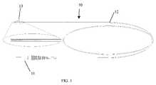
- FIG. 1is a schematic diagram illustrating an exemplary light applicator in accordance with at least one embodiment of the present disclosure.
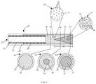
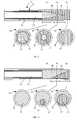
- FIGS. 2-7 and 9are cross-section views illustrating various exemplary light diffusing tips in accordance with various embodiments of the present disclosure.
- FIG. 8is an isometric view illustrating an exemplary light diffusing tip having reflective material overlaying a portion of the tip in accordance with at least one embodiment of the present disclosure
- FIGS. 10-13are cross-section views illustrating an exemplary method of manufacturing a light diffusing tip in accordance with at least one embodiment of the present disclosure.
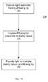
- FIG. 14is a flow chart illustrating an exemplary method for utilizing a light applicator in accordance with at least one embodiment of the present disclosure.
- FIGS. 1-14illustrate various exemplary light diffusing applicators and exemplary methods of their use and manufacture.
- the devices and methods described hereinmay find advantageous application in the treatment of solid cancerous tumors and other defects in soft tissue.
- a light diffusing applicatorincludes an optical waveguide designed for connection to an energy source and further includes an optical diffusing tip designed to cause cylindrical or substantially cylindrical scattering of light radiation around the axis of the optical waveguide.
- lightrefers to electromagnetic radiation within any of the infrared, visible, and ultraviolet spectra. Consequently, the term light transmissive, as used herein, is used in the context of the type of light implemented Exemplary sources of light may include, but are not limited to, lasers, light emitting diodes, arc lamps, light bulbs, flash lamps, and the like.
- the light applicator 10includes a connector 11 coupled to a proximal end of a flexible optical waveguide 12 and a light diffusing tip 13 optically and mechanically coupled to a distal end of the optical waveguide 12 .
- the connector 11couples to a light source (not shown) to receive light energy for transmission to the diffusing tip 13 via the waveguide 12 .
- An example of the connector 11includes the SMA905 fiber connector (available from Amphenol-Fiber Optic Products of Lisle, Ill.) which is frequently used for stable and reliable coupling to common lasers and other light sources.
- the diffusing tip 13scatters the light energy over a substantial portion of the diffusing tip 13 .
- the diffusing tip 13comprises a light transmissive housing having a monolithic scattering medium disposed within the housing, where the monolithic scattering medium includes two or more distinct scattering regions, each scattering region comprising a scattering material having scattering properties different from the scattering properties of the remaining scattering regions. Additionally, each scattering region may be coextensive along a length of the tubing with one or more adjacent scattering regions so that the diffusing tip exhibits a gradient in its scattering coefficient both axially and radially.
- the illustrated diffusing tip 23includes an optical waveguide 22 having one or, more optical fiber cores 24 surrounded by a cladding layer 25 and protective jacketing 26 .
- a portion of the distal end of the optical waveguide 22may be stripped of its outer protective jacketing 26 , thereby exposing the cladding 25 over a length of the fiber.
- the distal end of the optical waveguide 22is cleaved or polished flat, but other termination configurations, such as termination in a point, ball or at an angle, may be implemented as appropriate.
- the diffusing tip 23further includes an outer housing 28 to enclose scattering material and to provide a surface for bonding the diffusing tip 23 to the optical waveguide 22 .
- the outer housing 28preferably is composed of any of a variety of light transmissive materials, such as, for example, flexible PTFE or “Teflon,” polycarbonate, polyurethane, polyethylene, polypropylene, silicon, nylon, PVC, PET, ABS, PES, PEEK, FEP, as well as other flexible or rigid, radio-opaque or non radio-opaque materials as appropriate.
- the monolithic scattering medium disposed within the housing 28includes two scattering regions 30 and 31
- the scattering region 30includes a scattering material 32 having one or more scattering properties that are distinct from the scattering material 33 comprising the scattering region 3 1 .
- the scattering material 32 of the scattering region 30comprises scattering particles 34 suspended in a light transmissive material 35 and the scattering material 33 comprises scattering particles 36 suspended in a light transmissive material 37 .
- Examples of materials suitable for the scattering particles 34 and 36include, but are not limited to plastics, glasses, metals, metal oxides, or other particles known in the art to scatter optical radiation.
- An exemplary commercial product which may be implemented as scattering particles 34 or 36includes titanium dioxide particles available from Sigma-Aldrich Co. of St. Louis, Mo.
- Examples of materials suitable for the light transmissive materials 35 and 37include, but are not limited to, plastics (such as described above with reference to the housing 28 ), epoxies, and elastomers such as silicone or cyanoacrylates.
- An exemplary commercial product which may be implemented as materials 35 or 37includes Mastersil 151 two-part silicone epoxy available from Master Bond, Inc., of Hackensack, N.J. As depicted by FIG. 2 , the scattering material 32 (or, alternatively, the scattering material 33 ) further may be used as an adhesive to bond the housing 28 to the fiber core 24 and/or cladding 26 .
- the scattering material 32 and the scattering material 33have one or more different scattering properties.
- Different scattering properties between the scattering materials 32 and 33may be implemented by, for example, utilizing one type of scattering particle 34 (e.g., titanium dioxide) for scattering material 32 and a different type of scattering particle 36 (e.g., gold particles) for scattering material 33 .
- the scattering particles 34 and 36may be of different sizes and/or shapes so as to exhibit different scattering properties.
- the concentration of the scattering particles 34 in the material 32may be different than the concentration of scattering particles 36 in the material 37 so that the scattering materials 32 and 33 exhibit different scattering properties.
- the scattering materials 32 and 33also may be different from each other by a combination of any of scattering particle type, scattering particle size, scattering particle shape, scattering particle concentration or a transmissive material's index of refraction.
- the difference between the scattering properties of the two materials 32 and 33is represented by a difference in their scattering coefficients (i.e., a measure of the amount of light scattering exhibited by a material).
- the scattering materials 32 and 33are positioned within the housing 28 such that the scattering regions 30 and 31 are coextensive for, at least a portion 40 of the length of the housing 28 .
- the scattering regions 30 and 31are arranged such that the scattering region 31 forms a substantially cone shaped portion that is at least partially surrounded by material of the scattering region 30 , and thus the scattering regions 30 and 31 are coextensive along the housing 28 for part or all of the cone shaped region.
- the scattering regions 30 and 31may be formed so as to take on any of a variety of shapes in the coextensive portion 40 of the housing 28 as appropriate.
- the geometric relationship between the two scattering regions 30 and 31varies.
- the cross-sectional area of the scattering material 32decreases while the cross-sectional area of the scattering material 33 increases
- the scattering medium of the diffusing tipis made up of the scattering material 32
- the amount of scattering material 32 presentdecreases and the amount of scattering material 33 increases.
- the scattering element of the diffusing tip 23is almost entirely made up of the scattering material 33 .
- the proportion of the scattering material 33 to the scattering material 32i.e, the proportion of the scattering region 31 to the scattering region 30
- the proportion of the scattering region 31 to the scattering region 30generally increases from the proximal end to the distal end of the diffusing tip 23 .
- the distal end of diffusing tip 23may be made up entirely of scattering material 33 .
- the concentration and length of both the scattering region 30 and the scattering region 31 within the diffusing tip 23may be varied to achieve a desirable light distribution.
- longer diffusing tipsmay have lower concentration scattering regions or shorter lengths of higher concentration scattering regions.
- shorter diffusing tipsmay contain a shorter length of a low concentration scattering region and a longer length of a higher concentration scattering region.
- each scattering regionpreferably is selected to result in substantially uniform emission of light along the length of the diffusing tip.
- the scattering material 32may have a lower concentration of scattering particles 34 than the concentration of scattering particles 36 of the scattering material 33 and, therefore, the effective concentration of scattering particles increases over the coextensive portion 40 even as the intensity of the light energy decreases.
- it may be desirable to preferentially emit light over a given cross section of the diffusing tip 23which may be accomplished by concentrating scattering material having higher scattering coefficients at positions where more light is intended to exit the diffusing tip 23 .
- FIG. 3illustrates a diffusing tip 71 comprising a monolithic scattering medium disposed within the housing 28 and having two scattering regions 50 and 51 .
- FIG. 3illustrates a diffusing tip 71 comprising a monolithic scattering medium disposed within the housing 28 and having two scattering regions 50 and 51 .
- the diffusing tip 23 of FIG. 3illustrates a diffusing tip 71 comprising a monolithic scattering medium disposed within the housing 28 and having two scattering regions 50 and 51 .
- the scattering region 50includes a scattering material 52 having a substantially conical portion directed away from the termination of the fiber core 24 and the scattering region 51 includes a scattering material 53 having a region that at least partially surrounds the conical region and is therefore coextensive with the scattering material 52 over the portion 48 of the length of the diffusing tip 71
- the scattering material 52has a lower scattering coefficient than the scattering material 53 .
- the cross-sections 54 - 56 at positions 57 - 59respectively, illustrate, the proportion of the scattering material 52 to the scattering material 53 decreases, and the effective scattering coefficient therefore increases, as the distance from the termination of the fiber core 24 increases.
- FIG. 4illustrates another exemplary implementation of a diffusing tip having a monolithic scattering medium with two or more partially overlapping, distinct scattering regions.
- FIG. 4illustrates an exemplary diffusing tip having distinct scattering regions 60 and 61 , wherein the scattering region 61 comprises a substantially conical region surrounded by the scattering region 60 over portion 49 .
- the scattering region 60comprises a scattering material 62 having a first scattering property and the scattering region 61 comprises scattering material 63 having a second scattering property different from the first scattering property.
- the scattering region 61can be formed by allowing the scattering materials 62 and 63 to cure in the horizontal position or in a centrifuge, where the conical region 61 may settle due to gravity or centrifugal force.
- FIGS. 5-7exemplary diffusing tips having various caps secured to their distal ends are illustrated in accordance with at least one embodiment of the present disclosure.
- FIG. 5depicts a diffusing tip 73 having a pointed cap 74 that facilitates insertion of the fiber into tissues for interstitial applications.
- FIG. 6depicts a diffusing tip 83 having a rounded cap 84 that may be used in hollow organs or to minimize risk of vessel punctures during interstitial applications
- FIG. 7depicts a diffusing tip 93 having a blunt cap 94 that represents a third scattering region having a scattering material with a high scattering coefficient for further minimizing forward propagation of light from the distal end of the diffusing tip 93 .
- Blunt cap 94may also be made of a biocompatible material to prevent contact of scattering material with bodily tissue.
- FIG. 8depicts an exemplary diffusing tip 103 with a selective angular emission profile that is achieved using a reflective material 104 overlaying a section of the surface of the housing 28 of the diffusing tip 103 , where the reflective material 104 prevents light energy from passing through that section.
- Suitable materials for the reflective material 104include, for example, deposited surfaces of gold, silver, aluminum, chrome, nickel, or other reflective materials.
- the reflective material 104may be disposed either on the inner surface or outer surface of the housing 28 .
- the non-stick coating 114may include, for example, any of a number of light transmissive fluoropolymers with high temperature handling capability and non-stick surface properties with respect to thermally coagulated tissues Materials for the housing 28 can then be chosen based on the desired stiffness of the diffusing tip while the non-stick coating 114 of fluoropolymer provides the ideal surface properties. Alternatively, the non-stick coating 114 may be used to provide increased stiffness or durability for the diffusing tip 113 .
- a scattering material having a lower scattering coefficientis created, for example, by mixing a lower amount of scattering particles in an elastomer material to create a scattering material with a lower concentration of scattering particles.
- a scattering material having a higher scattering coefficientalso is created.
- the scattering material having a higher scattering coefficientmay be created by, for example, mixing a higher amount of scattering particles in an elastomer material to create a scattering material having a higher concentration of scattering particles.
- the scattering particle and elastomer mixturesmay include, for example, titanium dioxide particles mixed in silicone epoxy. In order to minimize or eliminate air bubbles in the scattering materials, a vacuum may be applied to the uncured silicone/titanium dioxide mixture prior to use.
- the scattering particle concentration range for the lower scattering coefficient material and the higher scattering coefficient materialvaries depending on the length and core diameter of the optical waveguide.
- a diffusing tip of for example, 10 mm in lengthtypically has a lower scattering coefficient material with a concentration of TiO 2 scattering particles preferably between 100 mg/ml and 180 mg/ml and more preferably between 145 mg/ml and 155 mg/ml.
- the higher scattering coefficient materialtypically has a concentration of TiO 2 scattering particles preferably between 2500 mg/ml and 6500 mg/ml and more preferably between 4400 mg/ml and 4650 mg/ml.
- the scattering regions formed from the scattering materialsalso may vary in length
- the length of the scattering region resulting from the lower scattering coefficient materialpreferably is between 1 mm and 100 mm, more preferably between 5 mm and 10 mm and even more preferably is about 6 mm.
- the length of the scattering region formed from the higher scattering coefficient materialpreferably is between 1 mm and 100 mm, more preferably is between 2 mm and 5 mm and even more preferably is about 4 mm.
- the shapes and lengths of each scattering region and the concentration of each scattering materialmay be varied to achieve the desired output profile for light emitted from the diffusing tip,
- lower scattering coefficient material 122is transferred to a first injector barrel 124 (e.g., a 3 cc barrel available from EFD, Inc. of East Buffalo, R.I.) supplied with a blunt ended needle 125 (e.g., a 27 Ga needle available from EFD, Inc.).
- a housing 126is positioned over the distal end of an optical waveguide 128 over a length where the protective jacket has previously been removed from the optical waveguide 128 .
- the housing 126includes a tubular housing having an outer diameter selected to substantially match the outer diameter of the optical waveguide's protective jacket so that a uniform surface profile is provided along the entire length of the resulting light applicator
- the wall thickness of the housing 126may be selected to allow space for a bonding region 130 between the inner wall of the housing 126 and the exposed cladding on the optical waveguide 128 .
- the needle 125is introduced into the distal end of the housing 126 and a plunger tip 131 within barrel 124 is actuated either manually or using a regulated dispenser (for example, the EFD Ultra Dispenser available from EFD, Inc.) to inject lower scattering coefficient material 122 into the lumen of the housing 126 .
- the lower scattering coefficient material 122may be injected until, for example, the distance 132 between the end of the optical waveguide 128 and the blunt ended needle 125 and approximately half the length 129 of housing 126 covering the exposed end of the optical waveguide 128 are filled.
- the needle 125may be removed from the distal end of the housing 126 while continuing to inject.
- the higher scattering coefficient material 134is transferred to a second injector barrel 136 supplied with a second blunt ended needle 137 .
- the needle 137then is positioned inside the distal end of the housing 126 .
- Actuation of plunger tip 138infuses higher scattering coefficient material 134 into a portion of the lower scattering coefficient material 122 which results in the formation of a discrete substantially cone-shaped portions of higher scattering coefficient material 134 within the lower scattering coefficient material 122 over a length 140 of the housing 126 .
- lower scattering coefficient material 122is forced toward the optical waveguide 128 and allowed to fill the bonding region 130 between the housing 126 and the exposed cladding of the optical waveguide 128 .
- the needle 137is removed from the housing 126 while continuing to inject.
- the higher scattering coefficient material 134may be inserted via the proximal end of the housing 126 and the optical waveguide 128 subsequently inserted before or during the curing of the scattering material 134 .
- the distal end of the resulting diffusing tip 143may be cut or otherwise trimmed to the appropriate length, and the finished tip/fiber assembly may be positioned vertically and the scattering materials 132 and 134 allowed to cure.
- the diffusing tip 143may be placed in a horizontal position or subjected to a centrifuge so as to cause the scattering particles of the scattering materials 132 and 134 to settle in one or more desired locations
- FIGS. 10-13illustrate, although injected as two separate preparations, the scattering materials 132 and 134 may be formulated of the same base material and thus cure into a monolithic scattering medium with spatially varying (both longitudinally and radially) scattering particle concentrations.
- the diffusing tipmay be formed by inserting one type of scattering material into the housing 126 and allowing the scattering material to partially or fully cure. A cavity is then formed in one end of the scattering material using, for example, a drill bit or scraping tool.
- a mold having the desired cavity shapemay be inserted into one end of the scattering material prior to curing and then removed after the first scattering material has at least partially cured.
- Another type of scattering materialthen is inserted into the housing 126 so that it occupies the cavity in formed the first scattering material. The second scattering material then may be left to cure and bond to the first scattering material so as to form the scattering medium of the resulting diffusing tip.
- any suitable arrangement of scattering regionsmay be implemented using the teachings provided herein without departing from the spirit or scope of the present disclosure.
- shape of the a scattering regionis generally described herein as being conical in shape and increasing linearly in size from proximal to distal ends, but alternatively its shape could have a non-linear taper, such as in accordance with Beer's Law, or other geometric shape and still achieve a desired effect.
- non-linear tapersuch as in accordance with Beer's Law
- the exemplary method 140initiates at step 142 wherein a light applicator having a diffusing tip (e.g., the light applicator 10 of FIG. 1 ) is obtained.
- the light applicatorthen may be affixed or otherwise coupled to a light source via the connector 11 ( FIG. 1 ).
- the diffusing tipis placed on or in a patient and the light diffusing tip is located proximate to the bodily tissue to be treated.
- the light sourceis activated and light energy is transmitted to the diffusing tip 13 ( FIG.
- the diffusing tip 13Upon reaching the diffusing tip 13 , the light is scattered along and out of the monolithic scattering medium in accordance with the scattering properties of the two or more distinct scattering regions of the monolithic scattering medium so as to irradiate the bodily tissue proximal to the diffusing tip 13 .
- the two or more scattering regionshave particular scattering properties and overlap in such a way so as to provide a substantially uniform light scattering along the length of the diffusing tip.
- the scattering regionsmay be arranged so as to concentrate the light scattering in certain areas or in certain directions.
- Specific implementations of the general method 140may include, for example LITT treatment of focal or metastatic tumors in brain, prostate, kidney, liver, breast, uterine, spinal, bone or other organs, as well as photodynamic therapy in hollow organs.
Landscapes
- Physics & Mathematics (AREA)
- Health & Medical Sciences (AREA)
- Biomedical Technology (AREA)
- General Physics & Mathematics (AREA)
- Optics & Photonics (AREA)
- Life Sciences & Earth Sciences (AREA)
- Engineering & Computer Science (AREA)
- Pathology (AREA)
- Biophysics (AREA)
- Nuclear Medicine, Radiotherapy & Molecular Imaging (AREA)
- Radiology & Medical Imaging (AREA)
- Animal Behavior & Ethology (AREA)
- General Health & Medical Sciences (AREA)
- Public Health (AREA)
- Veterinary Medicine (AREA)
- Radiation-Therapy Devices (AREA)
- Light Guides In General And Applications Therefor (AREA)
Abstract
Description
Claims (22)
Priority Applications (4)
| Application Number | Priority Date | Filing Date | Title |
|---|---|---|---|
| US11/777,856US7412141B2 (en) | 2004-11-16 | 2007-07-13 | Light diffusing tip |
| US12/169,602US7609927B2 (en) | 2004-11-16 | 2008-07-08 | Light diffusing tip |
| US12/559,267US20100016930A1 (en) | 2004-11-16 | 2009-09-14 | Light diffusing tip |
| US13/151,819US20110238139A1 (en) | 2004-11-16 | 2011-06-02 | Light diffusing tip |
Applications Claiming Priority (2)
| Application Number | Priority Date | Filing Date | Title |
|---|---|---|---|
| US10/989,894US7274847B2 (en) | 2004-11-16 | 2004-11-16 | Light diffusing tip |
| US11/777,856US7412141B2 (en) | 2004-11-16 | 2007-07-13 | Light diffusing tip |
Related Parent Applications (1)
| Application Number | Title | Priority Date | Filing Date |
|---|---|---|---|
| US10/989,894DivisionUS7274847B2 (en) | 2004-11-16 | 2004-11-16 | Light diffusing tip |
Related Child Applications (1)
| Application Number | Title | Priority Date | Filing Date |
|---|---|---|---|
| US12/169,602ContinuationUS7609927B2 (en) | 2004-11-16 | 2008-07-08 | Light diffusing tip |
Publications (2)
| Publication Number | Publication Date |
|---|---|
| US20080015560A1 US20080015560A1 (en) | 2008-01-17 |
| US7412141B2true US7412141B2 (en) | 2008-08-12 |
Family
ID=36386383
Family Applications (5)
| Application Number | Title | Priority Date | Filing Date |
|---|---|---|---|
| US10/989,894Expired - LifetimeUS7274847B2 (en) | 2004-11-16 | 2004-11-16 | Light diffusing tip |
| US11/777,856Expired - LifetimeUS7412141B2 (en) | 2004-11-16 | 2007-07-13 | Light diffusing tip |
| US12/169,602Expired - LifetimeUS7609927B2 (en) | 2004-11-16 | 2008-07-08 | Light diffusing tip |
| US12/559,267AbandonedUS20100016930A1 (en) | 2004-11-16 | 2009-09-14 | Light diffusing tip |
| US13/151,819AbandonedUS20110238139A1 (en) | 2004-11-16 | 2011-06-02 | Light diffusing tip |
Family Applications Before (1)
| Application Number | Title | Priority Date | Filing Date |
|---|---|---|---|
| US10/989,894Expired - LifetimeUS7274847B2 (en) | 2004-11-16 | 2004-11-16 | Light diffusing tip |
Family Applications After (3)
| Application Number | Title | Priority Date | Filing Date |
|---|---|---|---|
| US12/169,602Expired - LifetimeUS7609927B2 (en) | 2004-11-16 | 2008-07-08 | Light diffusing tip |
| US12/559,267AbandonedUS20100016930A1 (en) | 2004-11-16 | 2009-09-14 | Light diffusing tip |
| US13/151,819AbandonedUS20110238139A1 (en) | 2004-11-16 | 2011-06-02 | Light diffusing tip |
Country Status (4)
| Country | Link |
|---|---|
| US (5) | US7274847B2 (en) |
| EP (1) | EP1817618A4 (en) |
| CA (1) | CA2587691A1 (en) |
| WO (1) | WO2006055554A2 (en) |
Cited By (31)
| Publication number | Priority date | Publication date | Assignee | Title |
|---|---|---|---|---|
| US20090315816A1 (en)* | 2008-06-18 | 2009-12-24 | Samsung Electronics Co., Ltd. | Display apparatus |
| US20100016930A1 (en)* | 2004-11-16 | 2010-01-21 | Visualase, Inc. | Light diffusing tip |
| US20110176772A1 (en)* | 2009-11-18 | 2011-07-21 | Jessica Hixon | Methods and apparatus related to a distal end of a side-fire optical fiber having multiple capillary components |
| US20120051693A1 (en)* | 2010-08-31 | 2012-03-01 | Fujifilm Corporation | Light diffusing element and light guide for endoscopes equipped with the light diffusing element |
| US8149526B2 (en) | 2008-09-18 | 2012-04-03 | Photothera, Inc. | Single use lens assembly |
| US8979871B2 (en) | 2009-08-13 | 2015-03-17 | Monteris Medical Corporation | Image-guided therapy of a tissue |
| US9007696B2 (en) | 2007-11-12 | 2015-04-14 | Lightlab Imaging, Inc. | Imaging catheter with integrated reference reflector |
| US9091524B2 (en) | 2007-11-12 | 2015-07-28 | Lightlab Imaging, Inc. | Miniature optical elements for fiber-optic beam shaping |
| US9333038B2 (en) | 2000-06-15 | 2016-05-10 | Monteris Medical Corporation | Hyperthermia treatment and probe therefore |
| US9339336B2 (en) | 2003-11-07 | 2016-05-17 | Visualase, Inc. | Cooled laser fiber and method for improved thermal therapy |
| US9403029B2 (en) | 2007-07-18 | 2016-08-02 | Visualase, Inc. | Systems and methods for thermal therapy |
| US9433383B2 (en) | 2014-03-18 | 2016-09-06 | Monteris Medical Corporation | Image-guided therapy of a tissue |
| US9504484B2 (en) | 2014-03-18 | 2016-11-29 | Monteris Medical Corporation | Image-guided therapy of a tissue |
| US9610064B2 (en) | 2011-05-31 | 2017-04-04 | Desmond Adler | Multimodal imaging system, apparatus, and methods |
| US9702762B2 (en) | 2013-03-15 | 2017-07-11 | Lightlab Imaging, Inc. | Calibration and image processing devices, methods, and systems |
| US9996921B2 (en) | 2015-05-17 | 2018-06-12 | LIGHTLAB IMAGING, lNC. | Detection of metal stent struts |
| US10109058B2 (en) | 2015-05-17 | 2018-10-23 | Lightlab Imaging, Inc. | Intravascular imaging system interfaces and stent detection methods |
| US10188872B2 (en) | 2006-01-30 | 2019-01-29 | Pthera LLC | Light-emitting device and method for providing phototherapy to the brain |
| US10222956B2 (en) | 2015-05-17 | 2019-03-05 | Lightlab Imaging, Inc. | Intravascular imaging user interface systems and methods |
| US10327830B2 (en) | 2015-04-01 | 2019-06-25 | Monteris Medical Corporation | Cryotherapy, thermal therapy, temperature modulation therapy, and probe apparatus therefor |
| US10453190B2 (en) | 2015-11-23 | 2019-10-22 | Lightlab Imaging, Inc. | Detection of and validation of shadows in intravascular images |
| US10499813B2 (en) | 2014-09-12 | 2019-12-10 | Lightlab Imaging, Inc. | Methods, systems and apparatus for temporal calibration of an intravascular imaging system |
| US10593037B2 (en) | 2016-04-14 | 2020-03-17 | Lightlab Imaging, Inc. | Method, apparatus, and system to identify branches of a blood vessel |
| US10631754B2 (en) | 2016-05-16 | 2020-04-28 | Lightlab Imaging, Inc. | Intravascular absorbable stent detection and diagnostic methods and systems |
| US10646198B2 (en) | 2015-05-17 | 2020-05-12 | Lightlab Imaging, Inc. | Intravascular imaging and guide catheter detection methods and systems |
| US10675113B2 (en) | 2014-03-18 | 2020-06-09 | Monteris Medical Corporation | Automated therapy of a three-dimensional tissue region |
| US10729915B2 (en) | 2007-02-05 | 2020-08-04 | Novian Health, Inc. | Interstitial laser therapy control system |
| US10758743B2 (en) | 2001-11-01 | 2020-09-01 | Pthera LLC | Method for providing phototherapy to the brain |
| US11172821B2 (en) | 2016-04-28 | 2021-11-16 | Medtronic Navigation, Inc. | Navigation and local thermometry |
| US11287961B2 (en) | 2015-07-25 | 2022-03-29 | Lightlab Imaging, Inc. | Intravascular data visualization and interface systems and methods |
| US20240176057A1 (en)* | 2022-11-25 | 2024-05-30 | Proterial, Ltd. | Peripheral surface-emitting linear light guide and method for manufacturing the same |
Families Citing this family (74)
| Publication number | Priority date | Publication date | Assignee | Title |
|---|---|---|---|---|
| US8983257B2 (en)* | 2002-08-28 | 2015-03-17 | Nomir Medical Technologies, Inc. | Therapeutic light delivery apparatus, method, and system |
| EP1673644A1 (en)* | 2003-09-11 | 2006-06-28 | Philips Intellectual Property & Standards GmbH | Lamp system |
| US7356225B2 (en)* | 2004-07-22 | 2008-04-08 | Ondine International Ltd | Fiber optic probe tip |
| US8092507B2 (en) | 2007-02-05 | 2012-01-10 | Novian Health, Inc. | Interstitial energy treatment probe holders |
| CN101772642B (en)* | 2007-07-02 | 2015-06-17 | 博格华纳公司 | Inlet design for a pump assembly |
| CA2715813C (en)* | 2008-02-13 | 2017-03-21 | Erich Zurfluh | Light delivery device that provides a radial light output pattern |
| US9693826B2 (en) | 2008-02-28 | 2017-07-04 | Biolitec Unternehmensbeteiligungs Ii Ag | Endoluminal laser ablation device and method for treating veins |
| US20090257910A1 (en)* | 2008-04-10 | 2009-10-15 | Segal Jeremy P | Intravenous catheter connection point disinfection |
| US9770297B2 (en)* | 2008-06-04 | 2017-09-26 | Covidien Lp | Energy devices and methods for treating hollow anatomical structures |
| US8968186B2 (en) | 2008-06-23 | 2015-03-03 | Intubrite, Llc | Handle for fiber optic device |
| US9072446B2 (en) | 2008-06-23 | 2015-07-07 | Intubrite, Llc | Laryngoscope and method of use |
| US8012087B2 (en)* | 2008-06-23 | 2011-09-06 | Intubrite, Llc | Laryngoscope blade and method of use |
| US20090318768A1 (en)* | 2008-06-23 | 2009-12-24 | Tenger James P | Laryngoscope and Method of Use |
| US8152719B2 (en)* | 2008-06-23 | 2012-04-10 | Intubrite, Llc | Laryngoscope and method of use |
| USRE48598E1 (en) | 2008-06-23 | 2021-06-22 | Salter Labs | Laryngoscope and method of use |
| USD632787S1 (en) | 2009-11-03 | 2011-02-15 | Intubrite, Llc | Laryngoscope handle |
| US9095298B2 (en) | 2008-06-23 | 2015-08-04 | Intubrite, Llc | Adjustable display mechanism and method |
| US8257250B2 (en)* | 2008-06-23 | 2012-09-04 | Intubrite, Llc | Laryngoscope and method of use |
| US7862219B2 (en)* | 2008-10-22 | 2011-01-04 | Advanced Photodynamic Technologies, Inc. | Optical fiber light diffusing device |
| USD611598S1 (en) | 2009-02-10 | 2010-03-09 | Intubrite, Llc | Laryngoscope handle |
| USD609808S1 (en) | 2009-02-10 | 2010-02-09 | Intubrite, Llc | Laryngoscope blade |
| USD608889S1 (en) | 2009-02-10 | 2010-01-26 | Intubrite, Llc | Laryngoscope |
| US20110015621A1 (en)* | 2009-07-14 | 2011-01-20 | Invasix Corporation | Laser device for minimally invasive treatment of soft tissue |
| USD630739S1 (en) | 2009-12-21 | 2011-01-11 | Intubrite, Llc | Laryngoscope blade |
| USD630737S1 (en) | 2009-12-21 | 2011-01-11 | Intubrite, Llc | Laryngoscope blade |
| USD634008S1 (en) | 2009-12-21 | 2011-03-08 | Intubrite, Llc | Laryngoscope blade |
| USD630738S1 (en) | 2009-12-21 | 2011-01-11 | Intubrite, Llc | Laryngoscope blade |
| USD630743S1 (en) | 2009-12-23 | 2011-01-11 | Intubrite, Llc | Laryngoscope blade |
| USD630742S1 (en) | 2009-12-23 | 2011-01-11 | Intubrite, Llc | Laryngoscope blade |
| USD630745S1 (en) | 2009-12-23 | 2011-01-11 | Intubrite, Llc | Laryngoscope blade |
| USD630740S1 (en) | 2009-12-23 | 2011-01-11 | Intubrite, Llc | Laryngoscope blade |
| USD630744S1 (en) | 2009-12-23 | 2011-01-11 | Intubrite, Llc | Laryngoscope blade |
| USD630741S1 (en) | 2009-12-23 | 2011-01-11 | Intubrite, Llc | Laryngoscope blade |
| US11422308B2 (en)* | 2011-01-28 | 2022-08-23 | Koninklijke Philips N.V. | Tip reflection reduction for shape-sensing optical fiber |
| US8620125B2 (en) | 2011-04-29 | 2013-12-31 | Corning Incorporated | Light diffusing fibers and methods for making the same |
| WO2013095981A1 (en) | 2011-12-19 | 2013-06-27 | Corning Incorporated | Uniform uv efficient light diffusing fiber |
| US9295742B2 (en) | 2012-04-16 | 2016-03-29 | Puracath Medical, Inc. | System and method for disinfecting a catheter system |
| US9795466B2 (en) | 2012-05-30 | 2017-10-24 | Klox Technologies Inc. | Phototherapy devices and methods |
| US20140129618A1 (en)* | 2012-11-08 | 2014-05-08 | General Instrument Corporation | Method of streaming multimedia data over a network |
| WO2014120620A1 (en) | 2013-01-29 | 2014-08-07 | Puracath Medical, Inc. | Apparatus and method for disinfecting a catheter |
| USD733873S1 (en) | 2013-05-07 | 2015-07-07 | Novian Health Inc. | Probe holder |
| DE102014208756A1 (en)* | 2014-05-09 | 2015-11-12 | Schott Ag | Optical fiber with molded optical element |
| WO2015187943A1 (en) | 2014-06-05 | 2015-12-10 | Puracath Medical, Inc. | Transfer catheter for ultraviolet disinfection |
| WO2016040528A1 (en)* | 2014-09-10 | 2016-03-17 | Medical Instrument Development Laboratories, Inc. | Application of highly scattering materials to surgical illumination |
| FR3030061B1 (en)* | 2014-12-16 | 2021-02-12 | Sedi Ati Fibres Optiques | DIFFUSING MATERIAL |
| US20170348542A1 (en)* | 2015-01-19 | 2017-12-07 | Inserm (Institut National De La Sante Et De La Recherche Médicale) | System for treatment by photodynamic therapy and method for preparation of such system |
| CN108367085A (en) | 2015-03-18 | 2018-08-03 | 普拉卡斯医疗公司 | Disinfection by ultraviolet light conduit connection systems |
| US10918747B2 (en) | 2015-07-30 | 2021-02-16 | Vital Vio, Inc. | Disinfecting lighting device |
| KR102104951B1 (en) | 2015-07-30 | 2020-04-27 | 바이탈 바이오, 잉크. | Single diode disinfection |
| US10357582B1 (en) | 2015-07-30 | 2019-07-23 | Vital Vio, Inc. | Disinfecting lighting device |
| US9946023B2 (en)* | 2015-08-05 | 2018-04-17 | Huawei Technologies Co., Ltd. | Optical attenuator and fabrication method thereof |
| US10201480B2 (en)* | 2015-09-08 | 2019-02-12 | Cnicus, Llc | Feeding tube assembly with a light element attachable thereto |
| US10092356B2 (en)* | 2015-11-18 | 2018-10-09 | InnovaQuartz LLC | Radial emissions from optical fibers |
| US11826097B2 (en) | 2015-11-18 | 2023-11-28 | Cyclone Biosciences, Llc | Forming radial emissions from optical fibers |
| CN108291183A (en) | 2015-11-20 | 2018-07-17 | 康宁股份有限公司 | Illumination container for biological entities growth |
| JP2016173600A (en)* | 2016-06-01 | 2016-09-29 | オリンパス株式会社 | Optical device |
| US10295719B2 (en)* | 2016-10-25 | 2019-05-21 | Aspyrian Therapeutics Inc. | Cylindrical light diffusing device for use in photoimmunotherapy |
| AU2017378412B2 (en)* | 2016-12-16 | 2021-12-16 | Nanospectra Biosciences, Inc. | Devices and the use thereof in methods for ablation therapy |
| US20180185533A1 (en) | 2016-12-29 | 2018-07-05 | Vital Vio, Inc. | Control systems for disinfecting light systems and methods of regulating operations of disinfecting light systems |
| US10617774B2 (en) | 2017-12-01 | 2020-04-14 | Vital Vio, Inc. | Cover with disinfecting illuminated surface |
| US10309614B1 (en)* | 2017-12-05 | 2019-06-04 | Vital Vivo, Inc. | Light directing element |
| US10413626B1 (en) | 2018-03-29 | 2019-09-17 | Vital Vio, Inc. | Multiple light emitter for inactivating microorganisms |
| US10679472B2 (en)* | 2018-06-21 | 2020-06-09 | Plantronics, Inc. | Floating internal luminescent lighting |
| WO2020019305A1 (en)* | 2018-07-27 | 2020-01-30 | 尚华 | Photodynamic therapy and diagnosis device capable of optical fiber puncturing |
| WO2020090066A1 (en)* | 2018-10-31 | 2020-05-07 | オリンパス株式会社 | Phototherapy system and phototherapy method |
| CN109603010B (en)* | 2018-11-09 | 2019-07-26 | 尚华 | A kind of preparation method of even the optical fiber puncture needle of light and slit and light uniforming device out |
| US12194168B2 (en) | 2018-12-19 | 2025-01-14 | Vyv, Inc. | Lighting and dissipation device |
| US11639897B2 (en) | 2019-03-29 | 2023-05-02 | Vyv, Inc. | Contamination load sensing device |
| US11541135B2 (en) | 2019-06-28 | 2023-01-03 | Vyv, Inc. | Multiple band visible light disinfection |
| WO2021030748A1 (en) | 2019-08-15 | 2021-02-18 | Vital Vio, Inc. | Devices configured to disinfect interiors |
| US11878084B2 (en) | 2019-09-20 | 2024-01-23 | Vyv, Inc. | Disinfecting light emitting subcomponent |
| WO2021092024A1 (en)* | 2019-11-08 | 2021-05-14 | Laser Peripherals, Llc | Diffusing apparatus for laser therapy treatment |
| DE102021115485A1 (en)* | 2021-06-15 | 2022-12-15 | Schott Ag | Lighting system with a light guide with a diffuser element |
| EP4268754B1 (en)* | 2022-04-28 | 2024-05-29 | Oberon GmbH | Waveguide for treating inner walls of inner pathways of a human body |
Citations (64)
| Publication number | Priority date | Publication date | Assignee | Title |
|---|---|---|---|---|
| US4140130A (en) | 1977-05-31 | 1979-02-20 | Storm Iii Frederick K | Electrode structure for radio frequency localized heating of tumor bearing tissue |
| US4466697A (en) | 1981-11-12 | 1984-08-21 | Maurice Daniel | Light dispersive optical lightpipes and method of making the same |
| US4585298A (en) | 1982-08-26 | 1986-04-29 | Kei Mori | Photoradiator for radiating light |
| US4660952A (en) | 1984-02-23 | 1987-04-28 | Canon Kabuashiki Kaisha | Blade type shutter |
| US4669467A (en) | 1985-03-22 | 1987-06-02 | Massachusetts Institute Of Technology | Mode mixer for a laser catheter |
| US4693556A (en) | 1985-06-04 | 1987-09-15 | Laser Therapeutics, Inc. | Apparatus for producing a spherical pattern of light and method of manufacture |
| US4785815A (en) | 1985-10-23 | 1988-11-22 | Cordis Corporation | Apparatus for locating and ablating cardiac conduction pathways |
| US4832024A (en) | 1986-04-29 | 1989-05-23 | Georges Boussignac | Cardio-vascular catheter for shooting a laser beam |
| US4852567A (en) | 1988-01-21 | 1989-08-01 | C. R. Bard, Inc. | Laser tipped catheter |
| US4862887A (en) | 1987-05-29 | 1989-09-05 | Gesellschaft Fuer Strahlen Und Umweltforschung (Gsf) | Heart catheter |
| US4959063A (en) | 1988-05-12 | 1990-09-25 | Osada Research Institute, Ltd. | Spinal needle with optical fiber means for radiating a laser beam |
| US4986628A (en) | 1988-08-23 | 1991-01-22 | Lozhenko Alexandr S | Light guide device for phototherapy |
| US5042980A (en) | 1989-05-26 | 1991-08-27 | C. R. Bard, Inc. | Optical fiber diffusion tip for uniform illumination |
| US5061265A (en) | 1989-06-20 | 1991-10-29 | University Of Florida | Laser treatment apparatus and method |
| US5074632A (en) | 1990-03-07 | 1991-12-24 | Health Research, Inc. | Fiber optic diffusers and methods for manufacture of the same |
| DE4137983A1 (en) | 1990-12-19 | 1992-06-25 | Zeiss Carl Fa | Laser irradiation application appts. - has light wave conductor with scattering device in closed tubular case, transparent at end to laser |
| US5151096A (en) | 1991-03-28 | 1992-09-29 | Angiolaz, Incorporated | Laser catheter diffuser |
| US5169396A (en) | 1990-06-08 | 1992-12-08 | Kambiz Dowlatshahi | Method for interstitial laser therapy |
| US5196005A (en) | 1991-11-26 | 1993-03-23 | Pdt Systems, Inc. | Continuous gradient cylindrical diffusion tip for optical fibers and method for making |
| US5207669A (en) | 1989-05-26 | 1993-05-04 | C. R. Bard, Inc. | Optical fiber diffusion tip for uniform illumination |
| US5219346A (en) | 1990-01-09 | 1993-06-15 | Ciba-Geigy Corporation | Light diffuser for the photodynamic therapy of tumors in the oesophagus of a patient |
| US5246436A (en) | 1991-12-18 | 1993-09-21 | Alcon Surgical, Inc. | Midinfrared laser tissue ablater |
| US5269777A (en)* | 1990-11-01 | 1993-12-14 | Pdt Systems, Inc. | Diffusion tip for optical fibers |
| US5292320A (en) | 1992-07-06 | 1994-03-08 | Ceramoptec, Inc. | Radial medical laser delivery device |
| US5303324A (en) | 1992-10-29 | 1994-04-12 | American Cyanamid Company | Method and apparatus for providing controlled light distribution from a cylindrical fiberoptic diffuser |
| US5312392A (en) | 1992-08-31 | 1994-05-17 | Messerschmitt-Boelkow-Blohm Ag | Interstitial laser coagulation treatment for benign prostatic hyperplasia |
| US5337381A (en) | 1993-01-21 | 1994-08-09 | Fiberguide Industries | Fiber optic cylindrical diffuser |
| US5348552A (en) | 1991-08-30 | 1994-09-20 | Hoya Corporation | Laser surgical unit |
| US5363458A (en) | 1994-02-28 | 1994-11-08 | Fiber Guide Industries | Fiber optic light diffuser |
| US5373571A (en) | 1993-03-16 | 1994-12-13 | Spectran Specialty Optics Company | Fiber optic diffuser tip |
| US5429635A (en) | 1994-07-13 | 1995-07-04 | Pioneer Optics Company | Fiberoptic spherical diffuser |
| US5431647A (en) | 1994-07-13 | 1995-07-11 | Pioneer Optics Company | Fiberoptic cylindrical diffuser |
| US5441497A (en)* | 1994-07-14 | 1995-08-15 | Pdt Cardiovascular, Inc. | Light diffusing guidewire |
| US5454807A (en) | 1993-05-14 | 1995-10-03 | Boston Scientific Corporation | Medical treatment of deeply seated tissue using optical radiation |
| US5520681A (en) | 1992-04-24 | 1996-05-28 | Surgical Laser Technologies, Inc. | Light energy emitting probe with inclusions distributed within and throughout probe's tip portion |
| US5530780A (en) | 1993-12-20 | 1996-06-25 | Lederle (Japan), Ltd. | Fiber optic laser conducting and diffusion device |
| US5536265A (en) | 1994-03-25 | 1996-07-16 | Ciba-Geigy Corporation | Light diffuser and process for the manufacturing of a light diffuser |
| US5545161A (en) | 1992-12-01 | 1996-08-13 | Cardiac Pathways Corporation | Catheter for RF ablation having cooled electrode with electrically insulated sleeve |
| US5607421A (en) | 1991-05-01 | 1997-03-04 | The Trustees Of Columbia University In The City Of New York | Myocardial revascularization through the endocardial surface using a laser |
| US5688263A (en) | 1994-12-22 | 1997-11-18 | Dornier Medizintechnik Gmbh | Laser surgery applicator |
| US5754717A (en) | 1995-10-31 | 1998-05-19 | Indigo Medical, Incorporated | Light-diffusing device for an optical fiber, methods of producing and using same, and apparatus for diffusing light from an optical fiber |
| US5792100A (en) | 1995-05-19 | 1998-08-11 | Shantha; T. R. | Treatment method for transsphenoidal stimulation of the pituitary gland and of nerve structures |
| US5824005A (en) | 1995-08-22 | 1998-10-20 | Board Of Regents, The University Of Texas System | Maneuverable electrophysiology catheter for percutaneous or intraoperative ablation of cardiac arrhythmias |
| US5830196A (en) | 1995-09-21 | 1998-11-03 | Tyco Group S.A.R.L. | Tapered and reinforced catheter |
| US5871521A (en) | 1995-08-25 | 1999-02-16 | Matsushita Electric Industrial Co., Ltd. | Laser probe for medical treatment |
| US5906606A (en) | 1995-12-04 | 1999-05-25 | Target Therapuetics, Inc. | Braided body balloon catheter |
| US5908415A (en) | 1994-09-09 | 1999-06-01 | Rare Earth Medical, Inc. | Phototherapy methods and apparatus |
| US5947959A (en) | 1994-09-09 | 1999-09-07 | Rare Earth Medical, Inc. | Phototherapeutic apparatus with diffusive tip assembly |
| US5978541A (en)* | 1996-04-16 | 1999-11-02 | Miravant Systems, Inc. | Custom cylindrical diffusion tips |
| US5997571A (en) | 1997-12-17 | 1999-12-07 | Cardiofocus, Inc. | Non-occluding phototherapy probe stabilizers |
| US6004315A (en) | 1996-09-16 | 1999-12-21 | Focal, Inc. | Optical fiber diffuser and method of making |
| US6071302A (en)* | 1997-12-31 | 2000-06-06 | Cardiofocus, Inc. | Phototherapeutic apparatus for wide-angle diffusion |
| US6102905A (en) | 1994-09-09 | 2000-08-15 | Cardiofocus, Inc. | Phototherapy device including housing for an optical element and method of making |
| US6106514A (en) | 1996-08-12 | 2000-08-22 | O'donnell, Jr.; Francis E. | Laser method for subsurface cutaneous treatment |
| US6212426B1 (en) | 1995-07-28 | 2001-04-03 | Scimed Life Systems, Inc. | Systems and methods for conducting electrophysiological testing using high-voltage energy pulses to stun tissue |
| US6270492B1 (en)* | 1994-09-09 | 2001-08-07 | Cardiofocus, Inc. | Phototherapeutic apparatus with diffusive tip assembly |
| US6283958B1 (en) | 1996-04-04 | 2001-09-04 | Somatex Medizintechnische Instrumente Gmbh | Laser applicator set |
| US6343174B1 (en) | 1999-07-30 | 2002-01-29 | Ceramoptec Industries, Inc. | Laser delivery system with optical fibers having fluid delivery channels |
| US6361530B1 (en) | 2000-03-22 | 2002-03-26 | Indigo Medical Incorporated | Durable fiber optic diffuser tip and method of making same |
| US6383179B1 (en) | 1999-08-11 | 2002-05-07 | Ceramoptec Industries Inc. | Diode laser scalpel |
| US6418252B1 (en) | 2001-01-16 | 2002-07-09 | The Regents Of The University Of California | Light diffusing fiber optic chamber |
| US6503246B1 (en) | 2000-07-05 | 2003-01-07 | Mor Research Applications Ltd. | Cryoprobe and method of treating scars |
| US6554824B2 (en) | 2000-12-15 | 2003-04-29 | Laserscope | Methods for laser treatment of soft tissue |
| US7270656B2 (en) | 2003-11-07 | 2007-09-18 | Visualase, Inc. | Cooled laser fiber for improved thermal therapy |
Family Cites Families (8)
| Publication number | Priority date | Publication date | Assignee | Title |
|---|---|---|---|---|
| BE1003189A5 (en)* | 1990-07-27 | 1992-01-07 | B A Cosurvey Optics S P R L B | PRESSURE SENSOR. |
| US6325762B1 (en)* | 1996-12-09 | 2001-12-04 | Swee Chuan Tjin | Method and apparatus for continuous cardiac output monitoring |
| CA2273585A1 (en)* | 1999-05-28 | 2000-11-28 | Canpolar East Inc. | Sensors for detecting changes in temperature, ph, chemical conditions, biological conditions, radiation, electrical field and pressure |
| US7789876B2 (en)* | 2000-08-14 | 2010-09-07 | Tyco Healthcare Group, Lp | Method and apparatus for positioning a catheter relative to an anatomical junction |
| CA2475111A1 (en)* | 2002-02-05 | 2003-08-14 | Pharmacyclics, Inc. | Conical light diffuser and method of making |
| EP1496993B1 (en)* | 2002-04-24 | 2010-08-11 | Ludwig-Maximilians-Universität | Light applicator and method for producing a diffuser |
| WO2005004737A1 (en)* | 2003-06-30 | 2005-01-20 | Candela Corporation | Endovascular treatment of a blood vessel using a light source |
| US7274847B2 (en)* | 2004-11-16 | 2007-09-25 | Biotex, Inc. | Light diffusing tip |
- 2004
- 2004-11-16USUS10/989,894patent/US7274847B2/ennot_activeExpired - Lifetime
- 2005
- 2005-11-15WOPCT/US2005/041347patent/WO2006055554A2/enactiveApplication Filing
- 2005-11-15CACA002587691Apatent/CA2587691A1/ennot_activeAbandoned
- 2005-11-15EPEP05849640Apatent/EP1817618A4/ennot_activeWithdrawn
- 2007
- 2007-07-13USUS11/777,856patent/US7412141B2/ennot_activeExpired - Lifetime
- 2008
- 2008-07-08USUS12/169,602patent/US7609927B2/ennot_activeExpired - Lifetime
- 2009
- 2009-09-14USUS12/559,267patent/US20100016930A1/ennot_activeAbandoned
- 2011
- 2011-06-02USUS13/151,819patent/US20110238139A1/ennot_activeAbandoned
Patent Citations (69)
| Publication number | Priority date | Publication date | Assignee | Title |
|---|---|---|---|---|
| US4140130A (en) | 1977-05-31 | 1979-02-20 | Storm Iii Frederick K | Electrode structure for radio frequency localized heating of tumor bearing tissue |
| US4466697A (en) | 1981-11-12 | 1984-08-21 | Maurice Daniel | Light dispersive optical lightpipes and method of making the same |
| US4585298A (en) | 1982-08-26 | 1986-04-29 | Kei Mori | Photoradiator for radiating light |
| US4660952A (en) | 1984-02-23 | 1987-04-28 | Canon Kabuashiki Kaisha | Blade type shutter |
| US4669467A (en) | 1985-03-22 | 1987-06-02 | Massachusetts Institute Of Technology | Mode mixer for a laser catheter |
| US4693556A (en) | 1985-06-04 | 1987-09-15 | Laser Therapeutics, Inc. | Apparatus for producing a spherical pattern of light and method of manufacture |
| US4785815A (en) | 1985-10-23 | 1988-11-22 | Cordis Corporation | Apparatus for locating and ablating cardiac conduction pathways |
| US4832024A (en) | 1986-04-29 | 1989-05-23 | Georges Boussignac | Cardio-vascular catheter for shooting a laser beam |
| US4862887A (en) | 1987-05-29 | 1989-09-05 | Gesellschaft Fuer Strahlen Und Umweltforschung (Gsf) | Heart catheter |
| US4852567A (en) | 1988-01-21 | 1989-08-01 | C. R. Bard, Inc. | Laser tipped catheter |
| US4959063A (en) | 1988-05-12 | 1990-09-25 | Osada Research Institute, Ltd. | Spinal needle with optical fiber means for radiating a laser beam |
| US4986628A (en) | 1988-08-23 | 1991-01-22 | Lozhenko Alexandr S | Light guide device for phototherapy |
| US5042980A (en) | 1989-05-26 | 1991-08-27 | C. R. Bard, Inc. | Optical fiber diffusion tip for uniform illumination |
| US5207669A (en) | 1989-05-26 | 1993-05-04 | C. R. Bard, Inc. | Optical fiber diffusion tip for uniform illumination |
| US5061265A (en) | 1989-06-20 | 1991-10-29 | University Of Florida | Laser treatment apparatus and method |
| US5219346A (en) | 1990-01-09 | 1993-06-15 | Ciba-Geigy Corporation | Light diffuser for the photodynamic therapy of tumors in the oesophagus of a patient |
| US5074632A (en) | 1990-03-07 | 1991-12-24 | Health Research, Inc. | Fiber optic diffusers and methods for manufacture of the same |
| US5169396A (en) | 1990-06-08 | 1992-12-08 | Kambiz Dowlatshahi | Method for interstitial laser therapy |
| US5269777A (en)* | 1990-11-01 | 1993-12-14 | Pdt Systems, Inc. | Diffusion tip for optical fibers |
| DE4137983A1 (en) | 1990-12-19 | 1992-06-25 | Zeiss Carl Fa | Laser irradiation application appts. - has light wave conductor with scattering device in closed tubular case, transparent at end to laser |
| US5151096A (en) | 1991-03-28 | 1992-09-29 | Angiolaz, Incorporated | Laser catheter diffuser |
| US5607421A (en) | 1991-05-01 | 1997-03-04 | The Trustees Of Columbia University In The City Of New York | Myocardial revascularization through the endocardial surface using a laser |
| US5348552A (en) | 1991-08-30 | 1994-09-20 | Hoya Corporation | Laser surgical unit |
| US5196005A (en) | 1991-11-26 | 1993-03-23 | Pdt Systems, Inc. | Continuous gradient cylindrical diffusion tip for optical fibers and method for making |
| US5330465A (en)* | 1991-11-26 | 1994-07-19 | Laser Therapeutics, Inc. | Continuous gradient cylindrical diffusion tip for optical fibers and method for using |
| US5246436A (en) | 1991-12-18 | 1993-09-21 | Alcon Surgical, Inc. | Midinfrared laser tissue ablater |
| US5520681A (en) | 1992-04-24 | 1996-05-28 | Surgical Laser Technologies, Inc. | Light energy emitting probe with inclusions distributed within and throughout probe's tip portion |
| US5807390A (en) | 1992-04-24 | 1998-09-15 | Surgical Laser Technologies, Inc. | Light energy emitting probe with light-affecting inclusions distributed throughout |
| US5292320A (en) | 1992-07-06 | 1994-03-08 | Ceramoptec, Inc. | Radial medical laser delivery device |
| US5496308A (en) | 1992-07-06 | 1996-03-05 | Brown; Joseph | Radial laser delivery device |
| US5312392A (en) | 1992-08-31 | 1994-05-17 | Messerschmitt-Boelkow-Blohm Ag | Interstitial laser coagulation treatment for benign prostatic hyperplasia |
| US5303324A (en) | 1992-10-29 | 1994-04-12 | American Cyanamid Company | Method and apparatus for providing controlled light distribution from a cylindrical fiberoptic diffuser |
| US5545161A (en) | 1992-12-01 | 1996-08-13 | Cardiac Pathways Corporation | Catheter for RF ablation having cooled electrode with electrically insulated sleeve |
| US5337381A (en) | 1993-01-21 | 1994-08-09 | Fiberguide Industries | Fiber optic cylindrical diffuser |
| US5373571A (en) | 1993-03-16 | 1994-12-13 | Spectran Specialty Optics Company | Fiber optic diffuser tip |
| US5454807A (en) | 1993-05-14 | 1995-10-03 | Boston Scientific Corporation | Medical treatment of deeply seated tissue using optical radiation |
| US5530780A (en) | 1993-12-20 | 1996-06-25 | Lederle (Japan), Ltd. | Fiber optic laser conducting and diffusion device |
| US5363458A (en) | 1994-02-28 | 1994-11-08 | Fiber Guide Industries | Fiber optic light diffuser |
| US5536265A (en) | 1994-03-25 | 1996-07-16 | Ciba-Geigy Corporation | Light diffuser and process for the manufacturing of a light diffuser |
| US5429635A (en) | 1994-07-13 | 1995-07-04 | Pioneer Optics Company | Fiberoptic spherical diffuser |
| US5431647A (en) | 1994-07-13 | 1995-07-11 | Pioneer Optics Company | Fiberoptic cylindrical diffuser |
| US5441497A (en)* | 1994-07-14 | 1995-08-15 | Pdt Cardiovascular, Inc. | Light diffusing guidewire |
| US5908415A (en) | 1994-09-09 | 1999-06-01 | Rare Earth Medical, Inc. | Phototherapy methods and apparatus |
| US6270492B1 (en)* | 1994-09-09 | 2001-08-07 | Cardiofocus, Inc. | Phototherapeutic apparatus with diffusive tip assembly |
| US6102905A (en) | 1994-09-09 | 2000-08-15 | Cardiofocus, Inc. | Phototherapy device including housing for an optical element and method of making |
| US5947959A (en) | 1994-09-09 | 1999-09-07 | Rare Earth Medical, Inc. | Phototherapeutic apparatus with diffusive tip assembly |
| US5688263A (en) | 1994-12-22 | 1997-11-18 | Dornier Medizintechnik Gmbh | Laser surgery applicator |
| US5792100A (en) | 1995-05-19 | 1998-08-11 | Shantha; T. R. | Treatment method for transsphenoidal stimulation of the pituitary gland and of nerve structures |
| US6212426B1 (en) | 1995-07-28 | 2001-04-03 | Scimed Life Systems, Inc. | Systems and methods for conducting electrophysiological testing using high-voltage energy pulses to stun tissue |
| US5824005A (en) | 1995-08-22 | 1998-10-20 | Board Of Regents, The University Of Texas System | Maneuverable electrophysiology catheter for percutaneous or intraoperative ablation of cardiac arrhythmias |
| US5871521A (en) | 1995-08-25 | 1999-02-16 | Matsushita Electric Industrial Co., Ltd. | Laser probe for medical treatment |
| US5830196A (en) | 1995-09-21 | 1998-11-03 | Tyco Group S.A.R.L. | Tapered and reinforced catheter |
| US5946441A (en) | 1995-10-31 | 1999-08-31 | Indigo Medical, Inc. | Light-diffusing device for an optical fiber, methods of producing and using same, and apparatus for diffusing light from an optical fiber |
| US5754717A (en) | 1995-10-31 | 1998-05-19 | Indigo Medical, Incorporated | Light-diffusing device for an optical fiber, methods of producing and using same, and apparatus for diffusing light from an optical fiber |
| US5906606A (en) | 1995-12-04 | 1999-05-25 | Target Therapuetics, Inc. | Braided body balloon catheter |
| US6283958B1 (en) | 1996-04-04 | 2001-09-04 | Somatex Medizintechnische Instrumente Gmbh | Laser applicator set |
| US5978541A (en)* | 1996-04-16 | 1999-11-02 | Miravant Systems, Inc. | Custom cylindrical diffusion tips |
| US6106514A (en) | 1996-08-12 | 2000-08-22 | O'donnell, Jr.; Francis E. | Laser method for subsurface cutaneous treatment |
| US6004315A (en) | 1996-09-16 | 1999-12-21 | Focal, Inc. | Optical fiber diffuser and method of making |
| US5997571A (en) | 1997-12-17 | 1999-12-07 | Cardiofocus, Inc. | Non-occluding phototherapy probe stabilizers |
| US6071302A (en)* | 1997-12-31 | 2000-06-06 | Cardiofocus, Inc. | Phototherapeutic apparatus for wide-angle diffusion |
| US6343174B1 (en) | 1999-07-30 | 2002-01-29 | Ceramoptec Industries, Inc. | Laser delivery system with optical fibers having fluid delivery channels |
| US6383179B1 (en) | 1999-08-11 | 2002-05-07 | Ceramoptec Industries Inc. | Diode laser scalpel |
| US6361530B1 (en) | 2000-03-22 | 2002-03-26 | Indigo Medical Incorporated | Durable fiber optic diffuser tip and method of making same |
| US6576163B2 (en) | 2000-03-22 | 2003-06-10 | Indigo Medical, Incorporated | Durable fiber optic diffuser tip and method of making same |
| US6503246B1 (en) | 2000-07-05 | 2003-01-07 | Mor Research Applications Ltd. | Cryoprobe and method of treating scars |
| US6554824B2 (en) | 2000-12-15 | 2003-04-29 | Laserscope | Methods for laser treatment of soft tissue |
| US6418252B1 (en) | 2001-01-16 | 2002-07-09 | The Regents Of The University Of California | Light diffusing fiber optic chamber |
| US7270656B2 (en) | 2003-11-07 | 2007-09-18 | Visualase, Inc. | Cooled laser fiber for improved thermal therapy |
Non-Patent Citations (3)
| Title |
|---|
| U.S. Appl. No. 10/208,222, filed Jul. 30, 2002, entitled "Cooled Tip Laser Catheter for Sensing and Ablation of Cardiac Arrhythmias". |
| Weber et al., "Laser versus Radiofrequency Catheter Ablation of Ventricular Myocardium in Dogs: A COmparative Test," Cardiology, vol. 88, 1997, pp. 346-352. |
| Welch et al., "Evaluation of Cooling Techniques for the Protection of the Epidermis During Nd: YAG Laser Irradiation of the Skin," in Neodymium-YAG Laser in Medicine and Surgery, S.N. Joffe, Ed. New York: Elsevier, 1983, pp. 196-204. |
Cited By (66)
| Publication number | Priority date | Publication date | Assignee | Title |
|---|---|---|---|---|
| US9333038B2 (en) | 2000-06-15 | 2016-05-10 | Monteris Medical Corporation | Hyperthermia treatment and probe therefore |
| US9387042B2 (en) | 2000-06-15 | 2016-07-12 | Monteris Medical Corporation | Hyperthermia treatment and probe therefor |
| US10758743B2 (en) | 2001-11-01 | 2020-09-01 | Pthera LLC | Method for providing phototherapy to the brain |
| US10869721B2 (en) | 2003-11-07 | 2020-12-22 | Visualase, Inc. | Cooled laser fiber and method for improved thermal therapy |
| US9339336B2 (en) | 2003-11-07 | 2016-05-17 | Visualase, Inc. | Cooled laser fiber and method for improved thermal therapy |
| US20100016930A1 (en)* | 2004-11-16 | 2010-01-21 | Visualase, Inc. | Light diffusing tip |
| US12303709B2 (en) | 2006-01-30 | 2025-05-20 | Pthera, Llc | Light-emitting device and method for providing phototherapy to the brain |
| US11179572B2 (en) | 2006-01-30 | 2021-11-23 | Pthera LLC | Light-emitting device and method for providing phototherapy to the brain |
| US10188872B2 (en) | 2006-01-30 | 2019-01-29 | Pthera LLC | Light-emitting device and method for providing phototherapy to the brain |
| US10729915B2 (en) | 2007-02-05 | 2020-08-04 | Novian Health, Inc. | Interstitial laser therapy control system |
| US9403029B2 (en) | 2007-07-18 | 2016-08-02 | Visualase, Inc. | Systems and methods for thermal therapy |
| US11583338B2 (en) | 2007-07-18 | 2023-02-21 | Visualase, Inc. | Systems and methods for thermal therapy |
| US10433909B2 (en) | 2007-07-18 | 2019-10-08 | Visualase, Inc. | Systems and methods for thermal therapy |
| US9404731B2 (en) | 2007-11-12 | 2016-08-02 | Lightlab Imaging, Inc. | Miniature optical elements for fiber-optic beam shaping |
| US9091524B2 (en) | 2007-11-12 | 2015-07-28 | Lightlab Imaging, Inc. | Miniature optical elements for fiber-optic beam shaping |
| US9007696B2 (en) | 2007-11-12 | 2015-04-14 | Lightlab Imaging, Inc. | Imaging catheter with integrated reference reflector |
| US9864140B2 (en) | 2007-11-12 | 2018-01-09 | Lightlab Imaging, Inc. | Miniature optical elements for fiber-optic beam shaping |
| US20090315816A1 (en)* | 2008-06-18 | 2009-12-24 | Samsung Electronics Co., Ltd. | Display apparatus |
| US8085228B2 (en)* | 2008-06-18 | 2011-12-27 | Samsung Electronics Co., Ltd. | Display apparatus |
| US10071259B2 (en) | 2008-09-18 | 2018-09-11 | Pthera, Llc | Optical assembly |
| US8149526B2 (en) | 2008-09-18 | 2012-04-03 | Photothera, Inc. | Single use lens assembly |
| US10610317B2 (en) | 2009-08-13 | 2020-04-07 | Monteris Medical Corporation | Image-guided therapy of a tissue |
| US9271794B2 (en) | 2009-08-13 | 2016-03-01 | Monteris Medical Corporation | Monitoring and noise masking of thermal therapy |
| US9510909B2 (en) | 2009-08-13 | 2016-12-06 | Monteris Medical Corporation | Image-guide therapy of a tissue |
| US10188462B2 (en) | 2009-08-13 | 2019-01-29 | Monteris Medical Corporation | Image-guided therapy of a tissue |
| US9211157B2 (en) | 2009-08-13 | 2015-12-15 | Monteris Medical Corporation | Probe driver |
| US8979871B2 (en) | 2009-08-13 | 2015-03-17 | Monteris Medical Corporation | Image-guided therapy of a tissue |
| US20110176772A1 (en)* | 2009-11-18 | 2011-07-21 | Jessica Hixon | Methods and apparatus related to a distal end of a side-fire optical fiber having multiple capillary components |
| US8911433B2 (en)* | 2009-11-18 | 2014-12-16 | Boston Scientific Scimed, Inc. | Methods and apparatus related to a distal end of a side-fire optical fiber having multiple capillary components |
| US8849079B2 (en)* | 2010-08-31 | 2014-09-30 | Fujifilm Corporation | Light diffusing element and light guide for endoscopes equipped with the light diffusing element |
| US20120051693A1 (en)* | 2010-08-31 | 2012-03-01 | Fujifilm Corporation | Light diffusing element and light guide for endoscopes equipped with the light diffusing element |
| US9610064B2 (en) | 2011-05-31 | 2017-04-04 | Desmond Adler | Multimodal imaging system, apparatus, and methods |
| US11241154B2 (en) | 2011-05-31 | 2022-02-08 | Lightlab Imaging, Inc. | Multimodal imaging system, apparatus, and methods |
| US10548678B2 (en) | 2012-06-27 | 2020-02-04 | Monteris Medical Corporation | Method and device for effecting thermal therapy of a tissue |
| US11435233B2 (en) | 2013-03-15 | 2022-09-06 | Lightlab Imaging, Inc. | Calibration and image processing devices, methods, and systems |
| US9702762B2 (en) | 2013-03-15 | 2017-07-11 | Lightlab Imaging, Inc. | Calibration and image processing devices, methods, and systems |
| US10551251B2 (en) | 2013-03-15 | 2020-02-04 | Lightlab Imaging, Inc. | Calibration and image processing devices, methods, and systems |
| US9486170B2 (en) | 2014-03-18 | 2016-11-08 | Monteris Medical Corporation | Image-guided therapy of a tissue |
| US10342632B2 (en) | 2014-03-18 | 2019-07-09 | Monteris Medical Corporation | Image-guided therapy of a tissue |
| US10092367B2 (en) | 2014-03-18 | 2018-10-09 | Monteris Medical Corporation | Image-guided therapy of a tissue |
| US9700342B2 (en) | 2014-03-18 | 2017-07-11 | Monteris Medical Corporation | Image-guided therapy of a tissue |
| US9504484B2 (en) | 2014-03-18 | 2016-11-29 | Monteris Medical Corporation | Image-guided therapy of a tissue |
| US9492121B2 (en) | 2014-03-18 | 2016-11-15 | Monteris Medical Corporation | Image-guided therapy of a tissue |
| US10675113B2 (en) | 2014-03-18 | 2020-06-09 | Monteris Medical Corporation | Automated therapy of a three-dimensional tissue region |
| US9433383B2 (en) | 2014-03-18 | 2016-09-06 | Monteris Medical Corporation | Image-guided therapy of a tissue |
| US10499813B2 (en) | 2014-09-12 | 2019-12-10 | Lightlab Imaging, Inc. | Methods, systems and apparatus for temporal calibration of an intravascular imaging system |
| US11672583B2 (en) | 2015-04-01 | 2023-06-13 | Monteris Medical Corporation | Cryotherapy, thermal therapy, temperature modulation therapy, and probe apparatus therefor |
| US10327830B2 (en) | 2015-04-01 | 2019-06-25 | Monteris Medical Corporation | Cryotherapy, thermal therapy, temperature modulation therapy, and probe apparatus therefor |
| US10222956B2 (en) | 2015-05-17 | 2019-03-05 | Lightlab Imaging, Inc. | Intravascular imaging user interface systems and methods |
| US10646198B2 (en) | 2015-05-17 | 2020-05-12 | Lightlab Imaging, Inc. | Intravascular imaging and guide catheter detection methods and systems |
| US9996921B2 (en) | 2015-05-17 | 2018-06-12 | LIGHTLAB IMAGING, lNC. | Detection of metal stent struts |
| US10713786B2 (en) | 2015-05-17 | 2020-07-14 | Lightlab Imaging, Inc. | Detection of metal stent struts |
| US10902599B2 (en) | 2015-05-17 | 2021-01-26 | Lightlab Imaging, Inc. | Stent detection methods and imaging system interfaces |
| US10109058B2 (en) | 2015-05-17 | 2018-10-23 | Lightlab Imaging, Inc. | Intravascular imaging system interfaces and stent detection methods |
| US11532087B2 (en) | 2015-05-17 | 2022-12-20 | Lightlab Imaging, Inc. | Stent detection methods and imaging system interfaces |
| US11367186B2 (en) | 2015-05-17 | 2022-06-21 | Lightlab Imaging, Inc. | Detection of metal stent struts |
| US11768593B2 (en) | 2015-07-25 | 2023-09-26 | Lightlab Imaging, Inc. | Intravascular data visualization and interface systems and methods |
| US11287961B2 (en) | 2015-07-25 | 2022-03-29 | Lightlab Imaging, Inc. | Intravascular data visualization and interface systems and methods |
| US11850089B2 (en) | 2015-11-19 | 2023-12-26 | Lightlab Imaging, Inc. | Intravascular imaging and guide catheter detection methods and systems |
| US10453190B2 (en) | 2015-11-23 | 2019-10-22 | Lightlab Imaging, Inc. | Detection of and validation of shadows in intravascular images |
| US11475560B2 (en) | 2016-04-14 | 2022-10-18 | Lightlab Imaging, Inc. | Method, apparatus, and system to identify branches of a blood vessel |
| US10593037B2 (en) | 2016-04-14 | 2020-03-17 | Lightlab Imaging, Inc. | Method, apparatus, and system to identify branches of a blood vessel |
| US11172821B2 (en) | 2016-04-28 | 2021-11-16 | Medtronic Navigation, Inc. | Navigation and local thermometry |
| US12193783B2 (en) | 2016-04-28 | 2025-01-14 | Medtronic Navigation, Inc. | Navigation and local thermometry |
| US10631754B2 (en) | 2016-05-16 | 2020-04-28 | Lightlab Imaging, Inc. | Intravascular absorbable stent detection and diagnostic methods and systems |
| US20240176057A1 (en)* | 2022-11-25 | 2024-05-30 | Proterial, Ltd. | Peripheral surface-emitting linear light guide and method for manufacturing the same |
Also Published As
| Publication number | Publication date |
|---|---|
| US20080267570A1 (en) | 2008-10-30 |
| US20110238139A1 (en) | 2011-09-29 |
| EP1817618A2 (en) | 2007-08-15 |
| US7609927B2 (en) | 2009-10-27 |
| EP1817618A4 (en) | 2012-01-04 |
| US20100016930A1 (en) | 2010-01-21 |
| WO2006055554A2 (en) | 2006-05-26 |
| WO2006055554B1 (en) | 2007-04-12 |
| US7274847B2 (en) | 2007-09-25 |
| WO2006055554A3 (en) | 2007-02-08 |
| CA2587691A1 (en) | 2006-05-26 |
| US20080015560A1 (en) | 2008-01-17 |
| US20060104593A1 (en) | 2006-05-18 |
Similar Documents
| Publication | Publication Date | Title |
|---|---|---|
| US7412141B2 (en) | Light diffusing tip | |
| US5269777A (en) | Diffusion tip for optical fibers | |
| US5330465A (en) | Continuous gradient cylindrical diffusion tip for optical fibers and method for using | |
| US4660925A (en) | Apparatus for producing a cylindrical pattern of light and method of manufacture | |
| US6893432B2 (en) | Light-dispersive probe | |
| US12150705B2 (en) | Diffusing apparatus for laser therapy treatment | |
| US5303324A (en) | Method and apparatus for providing controlled light distribution from a cylindrical fiberoptic diffuser | |
| EP0582686B1 (en) | Apparatus using a laser lucent needle | |
| CA2127361C (en) | Cylindrical diffusion tips for optical fibers and method for making | |
| EP1689464B1 (en) | Cooled laser fiber for improved thermal therapy | |
| CN1026617C (en) | Optical fiber light diffuser and manufacturing method thereof | |
| US5908415A (en) | Phototherapy methods and apparatus | |
| US5997571A (en) | Non-occluding phototherapy probe stabilizers | |
| US5334206A (en) | Laser light irradiation apparatus | |
| KR101722008B1 (en) | Endoluminal laser ablation device and improved method for treating veins | |
| EP1547539A2 (en) | Photodynamic therapy light diffuser | |
| AU692730B2 (en) | Cylindrical diffusion tips for optical fibers and method for making | |
| Loschenov et al. | Developing system for delivery of optical radiation in medicobiological researches | |
| Sinofsky et al. | High-power diffusing-tip fibers for interstitial photocoagulation |
Legal Events
| Date | Code | Title | Description |
|---|---|---|---|
| STCF | Information on status: patent grant | Free format text:PATENTED CASE | |
| AS | Assignment | Owner name:BIOTEX, INC., TEXAS Free format text:ASSIGNMENT OF ASSIGNORS INTEREST;ASSIGNORS:GOWDDA, ASHOK;MCNICHOLS, ROGER;GELNETT, MARC;AND OTHERS;REEL/FRAME:023180/0794 Effective date:20041122 | |
| AS | Assignment | Owner name:VISUALASE, INC., TEXAS Free format text:ASSIGNMENT OF ASSIGNORS INTEREST;ASSIGNOR:BIOTEX, INC.;REEL/FRAME:023220/0012 Effective date:20090904 | |
| FPAY | Fee payment | Year of fee payment:4 | |
| AS | Assignment | Owner name:COMERICA BANK, A TEXAS BANKING ASSOCIATION, MICHIG Free format text:SECURITY AGREEMENT;ASSIGNOR:VISUALASE, INC.;REEL/FRAME:031393/0004 Effective date:20130911 | |
| AS | Assignment | Owner name:VISUALASE, INC., TEXAS Free format text:RELEASE OF SECURITY INTEREST;ASSIGNOR:COMERICA BANK;REEL/FRAME:033484/0516 Effective date:20140725 | |
| FEPP | Fee payment procedure | Free format text:PAT HOLDER NO LONGER CLAIMS SMALL ENTITY STATUS, ENTITY STATUS SET TO UNDISCOUNTED (ORIGINAL EVENT CODE: STOL); ENTITY STATUS OF PATENT OWNER: LARGE ENTITY | |
| FPAY | Fee payment | Year of fee payment:8 | |
| MAFP | Maintenance fee payment | Free format text:PAYMENT OF MAINTENANCE FEE, 12TH YEAR, LARGE ENTITY (ORIGINAL EVENT CODE: M1553); ENTITY STATUS OF PATENT OWNER: LARGE ENTITY Year of fee payment:12 | |
| AS | Assignment | Owner name:MEDTRONIC NAVIGATION, INC., COLORADO Free format text:MERGER;ASSIGNOR:VISUALASE INC.;REEL/FRAME:068967/0888 Effective date:20240821 |