US7412008B2 - Programmable phase mapping and phase rotation modulator and method - Google Patents
Programmable phase mapping and phase rotation modulator and methodDownload PDFInfo
- Publication number
- US7412008B2 US7412008B2US10/610,116US61011603AUS7412008B2US 7412008 B2US7412008 B2US 7412008B2US 61011603 AUS61011603 AUS 61011603AUS 7412008 B2US7412008 B2US 7412008B2
- Authority
- US
- United States
- Prior art keywords
- data
- symbol
- phase
- programmable
- rotated
- Prior art date
- Legal status (The legal status is an assumption and is not a legal conclusion. Google has not performed a legal analysis and makes no representation as to the accuracy of the status listed.)
- Expired - Lifetime, expires
Links
Images


Classifications
- H—ELECTRICITY
- H04—ELECTRIC COMMUNICATION TECHNIQUE
- H04L—TRANSMISSION OF DIGITAL INFORMATION, e.g. TELEGRAPHIC COMMUNICATION
- H04L27/00—Modulated-carrier systems
- H04L27/18—Phase-modulated carrier systems, i.e. using phase-shift keying
- H04L27/20—Modulator circuits; Transmitter circuits
- H04L27/2032—Modulator circuits; Transmitter circuits for discrete phase modulation, e.g. in which the phase of the carrier is modulated in a nominally instantaneous manner
- H04L27/2053—Modulator circuits; Transmitter circuits for discrete phase modulation, e.g. in which the phase of the carrier is modulated in a nominally instantaneous manner using more than one carrier, e.g. carriers with different phases
- H04L27/206—Modulator circuits; Transmitter circuits for discrete phase modulation, e.g. in which the phase of the carrier is modulated in a nominally instantaneous manner using more than one carrier, e.g. carriers with different phases using a pair of orthogonal carriers, e.g. quadrature carriers
- H04L27/2067—Modulator circuits; Transmitter circuits for discrete phase modulation, e.g. in which the phase of the carrier is modulated in a nominally instantaneous manner using more than one carrier, e.g. carriers with different phases using a pair of orthogonal carriers, e.g. quadrature carriers with more than two phase states
Definitions
- the inventionrelates generally to modulators and, more particularly, to phase shift keyed modulators.
- Modulatorstypically modulate baseband data prior to transmission by a radio transmitter in response to receiving the baseband data from a baseband processor.
- modulation of baseband dataalso refers to encoding of the baseband data if required.
- a modulatorconverts the baseband signal into a symbol, based on a mapping of the baseband data into one of a set of symbols as part of the process of modulating the baseband signal.
- phase shift keyed (PSK) modulatorsare known to receive symbol data and to convert the symbol data into phase data using M-phase PSK modulation, where M represents the number of possible phases corresponding to the size of the symbol set.
- a modulatormaps three consecutive bits of data from a baseband processor into one of eight symbols in an 8 phase PSK (8PSK) modulation format known as Gray coding.
- 8PSK8 phase PSK
- phase transitions for sequentially adjacent phase symbols that are 180 degrees, or ⁇ radians out of phaseexhibit zero crossings on a phase signal constellation map.
- Sequentially adjacent phase shift keyed signals that exhibit zero crossings in the phase signal constellation mapcreate higher bandwidth signal components, such as intermodulation signals and other spurious signals, as opposed to sequentially adjacent signals that do not cross zero in the phase constellation map.
- phase shift keyed signals that exhibit zero crossingsrequire the use of a very linear power amplifier in order to transmit the large bandwidth modulated signal.
- Phase shift keyed signal transitions for sequentially adjacent phase symbols that exhibit zero crossings in the phase signal constellation mapalso result in a high peak to average and high peak to minimum power ratio compared to signal transitions that do not cross zero in the phase signal constellation map.
- Modulated signals with a high peak to average and high peak to minimum power ratiomay saturate a power amplifier, creating greater interference noise in adjacent channels of a communication system.
- the interference noise in adjacent channelscan reduce communication system capacity.
- a second methodto minimize saturation of the power amplifier as a result of a modulated signal with a high peak to average and peak to minimum power ratio, the operating region of the power amplifier is reduced, which in turn reduces the power amplifier efficiency and further increases power consumption of the power amplifier. Consequently, modulated signals with high peak to average and peak to minimum power ratios require large bandwidths and additional power to operate, resulting in, for example, reduced battery life in a wireless device.
- each symbolmay be rotated when mapping the baseband data to a symbol; for example, each symbol may be rotated by a multiple of a predetermined phase rotation amount when using M-phase PSK modulation.
- This phase rotationreduces the zero crossings on the phase signal constellation map for sequentially adjacent phase modulated symbols, resulting in a modulated signal with reduced bandwidth and a reduction in the peak to average and peak to minimum power ratio of phase modulated signal.
- the phase rotation amountis not programmable in the modulator and, as a result, remains fixed. Consequently, this type of modulator cannot be used to communicate with modulation formats of different phase rotations, as used in different communication systems.
- each symbolmay be rotated by adding a fixed number to the symbol data to form a rotated symbol.
- the rotated symbolis then converted to an amount of rotation as a phase angle via lookup table.
- the rotation amountis not based on a symbol count to ensure that sequentially adjacent phase symbols do not exhibit zero crossings on a phase signal constellation map. Rather, the rotation amount is derived by adding a fixed number to each symbol received in the symbol data. Additionally, the rotation amount is not programmable in the modulator. Consequently, this type of modulator cannot be used to communicate with modulation formats of different phase rotations, as used in different communication systems.
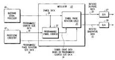
- FIG. 1is a block diagram illustrating one example of a modulator according to one embodiment of the invention
- FIG. 2is a flow chart illustrating one example of a programmable phase mapping method according to one embodiment of the invention
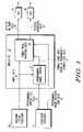
- FIG. 3is a block diagram illustrating an exemplary modulator including a table access circuit, according to another embodiment of the invention.
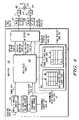
- FIG. 4is a block diagram illustrating another exemplary modulator including a rotation coefficient lookup table, according to yet another embodiment of the invention.
- FIG. 5is a block diagram illustrating one example of a wireless device according to an embodiment of the invention.
- a modulator and methodprovides a programmable phase rotation for supporting different modulation formats and different phase rotations.
- the modulatoremploys a symbol phase rotation logic and a programmable symbol counter that is operatively responsive to programmable phase rotation size data and programmable counter size data.
- Programmable phase rotation datadetermines an amount of phase rotation and programmable counter size data determines the maximum counter size. Accordingly, the modulator can be used to communicate with different modulation formats employing different phase rotation conventions as used in different communication systems.
- the symbol phase rotation logicis operative to produce rotated in-phase data and rotated quadrature data in response to receiving at least received symbol data, programmable phase rotation size data, and symbol count data based on programmable symbol counter size data.
- the symbol phase rotation logicmay include processing circuitry and associated memory that contains executable instructions for accessing a lookup table to produce the rotated in-phase data and the rotated quadrature data in response to receiving at least the received symbol data 24 , the symbol count data 34 based on the programmable counter size data 30 and the programmable phase rotation size data 36 .
- the symbol phase rotation logicmay produce dynamically selectable phase rotations that may be selected to better accommodate changes in channel characteristics in real time.
- the modulatormay be programmed to provide phase angle rotations for a phase shift key system capable of multiple phase modulation formats, using M-phase PSK, where M represents the number of possible phases corresponding to the size of the symbol set. Additionally, the modulator may support multiple modulation formats without requiring separate multiple dedicated modulators. Thus, a wireless device capable of functioning in multiple modulation formats may benefit from, among other things, the reduced size of using a single modulator as opposed to using multiple dedicated modulators. Further, the reduction of circuitry required for a single programmable multimode modulator may decrease power consumption for the wireless device.
- the modulatormay support multiple third generation (3 G) mobile communication systems, such as a universal mobile telecommunications service (UMTS) system, and an enhanced data rates for GSM evolution (EDGE) system.
- UMTSis based on wide band code division multiple access (WCDMA) technology.
- WCDMAwide band code division multiple access
- EDGEhas evolved from the existing time division multiple access (TDMA) standard of Global System for Mobile communications (GSM).
- GSMGlobal System for Mobile communications
- EDGEimproves spectral efficiency by applying the 8-phase QSK modulation format instead of binary Gaussian minimum-shift keying (GMSK), which is used in GSM.
- the modulatormay be designed to receive high input symbol data rates, thus allowing the modulator to be programmed for any existing or future modulation formats, including any communication standards to be developed in the future.
- a method for programming the modulator to produce programmable rotated in-phase data and rotated quadrature data in order to support communications with different modulation formats and different phase rotationsThe modulator receives symbol data representing a series of received symbols.
- the programmable symbol counterproduces symbol count data based at least on programmable symbol counter size data in response to receiving each of the symbols.
- the symbol phase rotation logicis programmed to produce the rotated in-phase data and the rotated quadrature data for each of the received symbols.
- FIG. 1is a block diagram illustrating one example of a modulator 10 operative to produce rotated in-phase data 20 and rotated quadrature data 22 in response to receiving symbol data 24 , for example, from a baseband signal processor 26 .
- the modulator 10may be coupled to digital to analog converters (D/A) 27 and 28 to convert the rotated in-phase data 20 and rotated quadrature data 22 into analog signals.
- the modulator 10includes symbol phase rotation logic 31 operatively coupled to a programmable symbol counter 32 .
- the programmable symbol counter 32receives the received symbol data 24 , and programmable counter size data 30 to produce symbol count data 34 .
- the programmable symbol counter 32may count sequentially up to the programmable counter size data 30 to produce symbol count data 34 .
- Symbol phase rotation logic 31receives the received symbol data 24 and programmable phase rotation size data 36 from processing circuitry 37 .
- processing circuitry 37may be part of a wireless device and may program the programmable symbol counter 32 with programmable counter size data 30 , and processing circuitry 37 may program the symbol phase rotation logic 31 with programmable phase rotation size data 36 , based on the modulation format and programmable phase rotation required for communication within a wireless communication system.
- Symbol phase rotation logic 31is operative to produce the rotated in-phase data 20 and the rotated quadrature data 22 in response to receiving at least the received symbol data 24 , the symbol count data 34 based on the programmable counter size data 30 , and the programmable phase rotation size data 36 .
- symbol phase rotation logic 31may be an ASIC, dedicated arithmetic circuit including adders, subtractors, shift logic, and control logic to covert digital symbol data 24 into the rotated in-phase data 20 and the rotated quadrature data 22 .
- symbol phase rotation logic 31may be one or more suitably programmed microprocessors, microcontrollers, DSPs (digital signal processors), or other processing circuitry, or any suitable combination of hardware, software, or firmware, and may include associated memory that contains a lookup table and executable instructions that, when executed, produce the rotated in-phase data 20 and the rotated quadrature data 22 in response to the lookup table receiving at least the received symbol data 24 , the symbol count data 34 , based on the programmable counter size data 30 , and the programmable phase rotation size data 36 .
- DSPsdigital signal processors
- the programmable counter size data 30 and the programmable phase rotation size data 36allow the modulator 10 to be programmed to support different phase rotations and different modulation formats.
- the modulator 10may support multiple modulation formats by programming the programmable symbol counter 32 with programmable counter size data 30 and by programming the symbol phase rotation logic 31 with programmable phase rotation size data 36 .
- the particular modulation format and phase rotationmay be determined or detected by the processing circuitry 37 within; for example, a wireless device based on the modulation format required for communication within a particular wireless communication system.
- the processing circuitry 37may program the symbol phase rotation logic 31 with the programmable counter size data 30 and the programmable phase rotation size data 36 by determining the required modulation format and phase rotation.
- the modulator 10can be used to communicate with modulation formats of different phase rotations as used in different communication systems.
- the symbol phase rotation logic 31produces substantially no zero crossings on a constellation phase map for sequentially adjacent rotated in-phase data 20 and rotated quadrature data 22 , based on at least the programmable phase rotation size data 36 .
- rotating each received symbol by the programmable phase rotation size data 36equivalent to an integral multiple of
- phase shift keyed signals that do not exhibit zero crossings in the phase signal constellation mapcreate lower bandwidth signals than signals that cross zero in the phase constellation map. Additionally, signals that do not cross zero on a constellation phase map produce less distortion and produce less error when demodulating a phase shift keyed signal than signals that exhibit zero crossing the phase signal constellation map. Additionally, the linearity requirements of a power amplifier that does not process signals that cross zero on a constellation phase map are less stringent due to the improved spectral efficiency.
- the symbol phase rotation logic 31dynamically varies a phase rotation of the rotated in-phase data 20 and a phase rotation of the rotated quadrature data 22 in response to at least a change in the programmable phase rotation size data 36 , and a change in the symbol count data 34 , based on the programmable counter size data 30 .
- the programmable phase rotation size data 36may be changed dynamically during a communication, such as during a telephone call, to better accommodate changes in channel characteristics in real time. Changes in channel characteristics may affect the quality of the communication channel.
- the symbol phase rotation logic 31produces rotated in-phase data 20 and rotated quadrature data 22 , having phase transitions for sequentially adjacent phase symbols that have reduced zero crossings on a phase signal constellation map.
- phase shift key signals that exhibit reduced zero crossings in the phase signal constellation mapcreate reduced bandwidth signals and reduced peak to average and peak to minimum power ratios, as opposed to signals that more frequently cross zero in the phase constellation map.
- the hardware and software required to produce the phase rotationmay be simplified, thus reducing the cost and expense of developing the symbol phase rotation logic 31 to produce no zero crossings in the phase constellation map, while realizing some benefit such as reduced bandwidth.
- the baseband processing circuit 26produces baseband digital data for conversion into symbol data 24 , based on grouping a predetermined number of bits from the baseband digital data and associating the grouped bits into a symbol selected from a predetermined set of symbols, as known in the art.
- the baseband signal processor 26may provide the symbol data 24 in any suitable format, such as serial data, or parallel data. Further, the baseband signal processor 26 may parse the baseband digital data, for example, in sequential groups of three bits, where each group of three bits represents one symbol from a set size of eight symbols.
- the received symbol data 24may be selected from a group of M symbols where the symbol phase rotation logic 31 represents each of the symbols as one of M possible phases.
- Mmay be an integer that represents the number of possible phases corresponding to the size of the symbol set.
- the programmable counter size data 30is based on at least M, such as 2 M, so that the symbol counter size is associated with the number of possible phases.
- the programmable phase rotation size data 36is based on at least M, so that the number of phase rotations is associated with the number of possible phases and the symbol counter size.
- each symbol received from the symbol data 24may be mapped to one of M possible phase angles, and rotated by a programmable amount determined by the programmable phase rotation size data 36 .
- Thisallows a programmable phase angle rotation for each of the received M-phase PSK symbols, based at least on the symbol count data 34 .
- the programmable counter size data 30may be based on a power of two, such as two, four, eight, sixteen, thirty-two, sixty-four, and so on.
- the counter size data 30may be any suitable number not necessarily based on a power of two.
- the programmable phase rotation size data 34may be sixteen or even a number other than sixteen, such as ten, eleven, or twenty, or any other suitable number.
- the symbol datais represented as a sequence of symbols, each corresponding to one out of at least eight possible phases.
- the phase rotation for each symbolis an integral multiple N of the programmable phase rotation size data 36 , such as a multiple of
- the programmable symbol counter 32produces a symbol count 34 , N, that is used as a multiplier to the programmable phase rotation size data 36 .
- Nthe symbol count 34
- the symbol phase rotation logic 31will produce a rotation by multiplying the symbol count data 34 , six in this example, with the programmable phase rotation size data 36 , 3 ⁇ /8 radians, in this example, to produce a rotation amount of
- the programmable symbol counter 32may be a wrap-around counter such that as each symbol from the symbol data 24 is received, the programmable symbol counter 32 will count from zero to a maximum number established by the programmable counter size data 30 . For example, if the programmable counter size data 30 is fifteen, then the programmable symbol counter 32 will count from zero to fifteen and then wrap around to zero after the next symbol is received.
- the programmable symbol counter 32may be a shift register, suitable pattern generator, or suitable logic for providing symbol count data 34 to symbol phase rotation logic 31 .
- FIG. 2illustrates a method 200 beginning with step 210 for producing rotated in-phase data 20 and rotated quadrature data 22 .
- the method 200will be described with respect to FIG. 1 , but is not limited thereto.
- the method 200may be carried out by the modulator 10 . However, any other suitable structure may also be used. It will be recognized that the method 200 will be described as a series of operations, but the operations may be performed in any suitable order.
- Modulator 10 at step 220receives symbol data 24 representing a series of received symbols.
- baseband signal processor 26may receive baseband data, either serially or in parallel, and convert the baseband data into one of a set of M symbols to generate the symbol data 24 as known in the art.
- the baseband signal processor 26may parse the baseband digital data based on successive groupings of bits associated with a symbol within the symbol set size M. For example, in eight-phase PSK modulation, the baseband processor 26 may group successive groups of three bits or may parse successive groups of three bits in order to convert each group of three bits into one of eight symbols through a bit to symbol mapping function.
- programmable symbol counter 32produces symbol count data 34 based at least on programmable counter size data 30 in response to receiving each of the symbols from the symbol data 24 .
- the programmable symbol counter 32may sequentially count the number of symbols received in the symbol data 24 to produce the symbol count data 34 up to the programmable counter size data 30 , in response to receiving each of the symbols within the predefined symbol set.
- the generation of the symbol count data 34 at step 230may be performed by counting each of the received symbols from received symbol data 24 to produce corresponding symbol count data 34 .
- the symbol count data 34may be compared to the programmable counter size data 30 each time a symbol in the symbol data 24 is received. If the symbol count data 34 is equal to the programmable counter size data 30 , then the symbol count data 34 may be reset to an initial symbol count value, such as zero.
- the programmable counter size data 30is, for example, fifteen. Accordingly, the symbol count data 34 will count from zero to fifteen for every symbol received in the symbol data 24 .
- the symbol count data 34is reset to zero, or the symbol count data 34 wraps around to zero. If the symbol count data 34 is not equal to the programmable counter size data 30 , then the symbol count data 34 is incremented as previously described.
- symbol phase rotation logic 31produces the rotated in-phase data 20 and the rotated quadrature data 22 in response to receiving a corresponding symbol out of the symbol set M from the received symbol data 24 , the corresponding symbol count data 34 based on the programmable counter size data 30 , and the programmable phase rotation size data 36 . Accordingly, each symbol received as part of the received symbol data 24 will be ultimately converted to rotated in-phase data 20 and rotated quadrature data 22 . As a result of no, or the reduced number of zero, crossings, the bandwidth is reduced for the resulting signal represented by the rotated in-phase data 20 and the rotated quadrature data 22 .
- a phase rotation of the rotated in-phase data 20 and a phase rotation of the rotated quadrature data 22is dynamically varied in response to any change of the programmable phase rotation size data 36 and any change in the symbol count data 34 based the programmable symbol counter size data 36 .
- FIG. 3illustrates a modulator 300 according to one exemplary embodiment of the invention.
- the symbol phase rotation logic 31includes a storage element 301 , such as a memory device, operatively coupled to a table access circuit 302 .
- the storage element 40includes data representing a phase rotation table 304 containing at least the rotated in-phase data 20 and the rotated quadrature data 22 for rotating a phase associated with at least the received symbol data 24 .
- the table access circuit 302produces the rotated in-phase data 20 , and the rotated quadrature data 22 , in response to the symbol data 24 , and a rotation amount received from the phase rotation table 304 of storage element 301 .
- a phase rotationis applied to the symbol data 24 , in response to the symbol count data 34 , the programmable counter size data 30 , and the programmable phase rotation size data 36 .
- the symbol count data 24is six
- the programmable phase rotation size data 36is
- phase rotation table 304is such that the symbol data 24 may be converted to a rotated phase for any symbol in the symbol set and for any combination of programmable phase rotation size data 36 , symbol count data 34 , and programmable counter size data 30 .
- phase rotation table 304is at least a three dimensional lookup table that provides a rotation amount based on any combination of programmable phase rotation size data 36 , symbol count data 34 , and programmable counter size data 30 .
- the phase rotation table 304may be programmed to produce substantially no zero crossings, or a reduced number of zero crossings on a constellation phase map for sequentially adjacent rotated in-phase data 20 and rotated quadrature data 22 .
- substantially no zero crossingsor a reduced number of zero crossings on a constellation phase map for sequentially adjacent rotated in-phase data 20 and rotated quadrature data 22 .
- rotating each received symbolby an integral multiple of
- Nis the symbol count data 34 , substantially reduces or eliminates zero crossings on a constellation phase map for sequentially adjacent rotated in-phase data 20 and rotated quadrature data 22 .
- the table access circuit 302 and the phase rotation table 304convert each individual symbol from symbol data 24 to produce the required rotated in-phase data 20 and the rotated quadrature data 22 .
- the table access circuit 302obtains a rotation amount to produce the rotated in-phase data 20 and a rotation amount to produce the rotated quadrature data 22 stored in storage element 40 .
- the rotation amounts necessary to produce the rotated in-phase data 20 and the rotated quadrature data 22may be stored in storage element 40 using any suitable coordinate system, such as a Cartesian coordinate system or a polar coordinate system.
- Rotation amounts to produce the rotated in-phase data 20 and rotated quadrature data 22may be represented in the polar coordinate system simply as an angle, where the magnitude for each data entry is unity, and as such, does not change unless the phase data is amplitude modulated.
- the table sizeif using Cartesian coordinates, would include real and imaginary entries corresponding to in-phase and quadrature rotation amount data.
- the table access circuit 302is capable of converting any symbol from a plurality of symbol sets M for any possible symbol count data 34 , based on a plurality of programmable counter size data 30 , and a plurality of programmable phase rotation size data 36 . Accordingly, the table access circuit 302 is capable of dynamically varying a phase rotation of the rotated in-phase data 20 and a phase rotation of the rotated quadrature data 22 , in response to any changes in the programmable phase rotation size data 36 , any changes in the symbol count data 34 , and any changes on the programmable counter size data 30 . As a result, the table access circuit 302 may be programmed to allow a switch from one modulation format to any other type of modulation format, such as, for example, GSM, EDGE, CDMA and UMTS or any suitable existing or future modulation format.
- any other type of modulation formatsuch as, for example, GSM, EDGE, CDMA and UMTS or any suitable existing or future modulation format.
- symbol phase rotation logic 31was described above as being a table access circuit 302 and a storage element 301 having a phase rotation table 304 , it will be recognized that the symbol phase rotation logic 31 may be implemented using any logic such as discrete logic, an ASIC, or a DSP programmed to produce the rotated in-phase data 20 and the rotated quadrature data 22 , such that substantially no zero crossings occur, or a reduced number of zero crossings occur, on a constellation phase map for sequentially adjacent rotated in-phase data 20 and rotated quadrature data 22 , or any suitable sequence of data.
- any logicsuch as discrete logic, an ASIC, or a DSP programmed to produce the rotated in-phase data 20 and the rotated quadrature data 22 , such that substantially no zero crossings occur, or a reduced number of zero crossings occur, on a constellation phase map for sequentially adjacent rotated in-phase data 20 and rotated quadrature data 22 , or any suitable sequence of data.
- FIG. 4illustrates a modulator 400 according to another exemplary embodiment, where the phase rotation table 304 further includes a symbol to phase angle lookup table 440 and a rotation coefficient lookup table 460 .
- the symbol to phase angle lookup table 440contains at least unrotated in-phase data 50 and unrotated quadrature data 52 corresponding to the received symbol data 34 . Accordingly, the symbol to phase angle lookup table 440 contains entries for each possible symbol in the symbol set, i.e., M for an M-phase PSK modulation format as known in the art.
- the symbol to phase angle lookup table 440contains real and imaginary entries in a Cartesian coordinate system, however, any coordinate system such as a polar coordinate system or any other suitable coordinate system may be used as previously discussed.
- rotation coefficient lookup table 460contains at least real rotation coefficient data 54 and imaginary rotation coefficient data 56 in, for example, a Cartesian or polar coordinate system or other suitable system corresponding to the received symbol count data 34 based at least on the programmable counter size data 30 .
- the table access circuit 302produces the rotated in-phase data 20 and the rotated quadrature data 22 , in response to receiving the unrotated in-phase data 50 and unrotated quadrature data 52 from the symbol to phase angle lookup table 440 , and in response to receiving the real rotation coefficient data 54 and the imaginary rotation coefficient data 56 from the rotation coefficient lookup table 460 .
- the table access circuit 302may multiply the unrotated in-phase data 50 and unrotated quadrature data 52 with the real rotation coefficient data 54 , and the imaginary rotation coefficient data 56 using, for example, a DSP programmed to perform the multiplication, or logic such as an ASIC, or any other suitable device or method.
- the symbol to phase angle lookup table 440 and the rotation coefficient lookup table 460contain entries for producing rotated in-phase data 20 and rotated quadrature data 22 for any anticipated combination of symbol data 24 , programmable phase rotation size data 36 , symbol count data 34 and programmable counter size data 30 .
- each symbol of symbol data 24may be represented as one out of eight possible phases using eight-phase PSK modulation
- the symbol to phase-angle lookup table 440 and rotation coefficient lookup table 460may be programmed to provide one of sixteen phase positions on a constellation map for a symbol set size of eight.
- the programmable phase rotation size data 36is 3 ⁇ /8.
- the size of the programmable counter size data 30is at least fifteen so that the symbol count data 34 will count from zero to fifteen.
- the symbol count data 34may be represented by four bits.
- the symbol to phase angle lookup table 440contains entries for converting each of the M symbols received from symbol data 24 into real unrotated in-phase data 50 and imaginary unrotated quadrature data 52 for each phase angle associated with a symbol. For example, using eight phase PSK modulation, there are eight symbols in the symbol set. Therefore, the symbol to phase angle lookup table 440 will have at least eight rows having real and imaginary entries representing the eight symbols in the symbol set. For example, the symbol value of two received from symbol data 24 would be represented in the phase angle look up table 440 as an unrotated phase angle of ⁇ /2 radians.
- the rotation coefficient lookup table 460Since the number of rows for the rotation coefficient lookup table 460 corresponds to the counter size in this example, the number of rows corresponds directly with the programmable counter size data 30 .
- the rotation coefficient lookup table 460represents a table having at least sixteen rows and two columns if the database is represented in a Cartesian coordinate system, one column for real numbers and one column for imaginary numbers. Therefore, each entry of the rotation coefficient lookup table 460 represents the real and imaginary part of a rotation amount based on the programmable counter size data 30 and the programmable phase rotation size data 36 .
- each entry in the rotation coefficient lookup table 460may be determined by multiplying the programmable phase rotation size data 36 with the current symbol count data 34 associated with the incoming symbol from symbol data 24 . For example, if a particular symbol received in symbol data 24 has associated with it a current symbol count data of two, then the symbol count data 34 points to the second row of the rotation coefficient lookup table 460 containing the product of the programmable phase rotation size data 36 , in this case
- the symbol value of two received from symbol data 24corresponds to the unrotated phase angle of ⁇ /2 radians and is rotated by 3 ⁇ /4 radians resulting in a rotated phase angle of 5 ⁇ /4 radians or simply as ⁇ /4 radians in the constellation phase map.
- the rotation coefficient lookup table 460 and the symbol to phase angle lookup table 440may contain entries for multiple values of programmable phase rotation size data 36 , multiple values of programmable counter size data 30 , and for multiple numbers of symbol size sets M.
- the symbol to phase angle lookup table 440may contain entries for symbol size sets of four, eight, sixteen, thirty-two, sixty-four, or any suitable symbol size set M.
- the symbol to phase angle lookup table 440provides phase angles for a symbol size set of eight and for a programmable counter size data 30 of sixteen.
- the symbol to phase angle lookup table 440may also provide phase angles for a symbol size set of sixteen and programmable counter size data of thirty-two. Accordingly, the symbol to phase angle lookup table 440 may have multiple sets or subsets of lookup tables in order to respond to any dynamic change of the symbol size set, the programmable phase rotation size data 36 and programmable counter size data 30 .
- the rotation coefficient lookup table 460may have multiple sets or subsets of look up tables to provide rotation coefficients based on multiple programmable counter size data 30 and multiple programmable phase rotation size data 36 .
- the rotation coefficient lookup table 460may have subtables corresponding to programmable counter size data 30 that may be of multiple sets of subtable values such as eight, sixteen, thirty-two, sixty-four, one hundred twenty-eight, two hundred fifty-six or any suitable value.
- the rotation coefficient lookup table 460may have multiple subtables for programmable phase rotation size data 36 such as
- the programmable counter size data 30is not based on a power of two and therefore may be any suitable number such as twenty, thirty-eight, sixty.
- the rotation coefficient lookup table 460will provide the appropriate rotation coefficients based on the value of the programmable counter size data 30 . Further, the rotation coefficient lookup table 460 may dynamically change the rotation coefficients based on any dynamic change of the programmable counter size data 30 .
- the actual rotation values within the rotation coefficient lookup table 460may also be dynamically changed based on the programmable phase rotation size data 36 .
- one subtable of the rotation coefficient lookup table 460may provide rotation values based on
- multiple subtables within the rotation coefficient lookup table 460 and within the symbol to phase angle lookup table 440may be predefined so that the table access circuit 302 may access any of the subtables dynamically based on any combination of symbol size set M, symbol count data 34 , programmable counter size data 30 , and programmable phase rotation size data 36 .
- modulator 10includes a multiplier 58 operatively coupled to the table access circuit 302 to multiply the unrotated in-phase data 50 and the unrotated quadrature data 52 with real rotation coefficient data 54 and imaginary rotation coefficient data 56 to generate the rotated in-phase data 20 and the rotated quadrature data 22 .
- multiplier 58performs complex multiplication as described according to one embodiment below. For example, multiplier 58 may perform the following complex multiplication as expressed in the formulas below. (I+jQ)(RealC+jImC)
- the unrotated in-phase data 50is represented by I
- the unrotated quadrature data 52is represented by jQ
- the real rotation coefficient data 54is represented as RealC
- the imaginary rotation coefficient data 56is represented by jImC.
- the product of these two termsis shown below. (IRealC+jIImC+jQRealC ⁇ QImC)
- the multiplier 58may be implemented in any suitable manner such as a dedicated complex multiplier hardware using, for example an ASIC, in software processed on a digital signal processor, microprocessor or any suitable processing circuit or, as with any combination of hardware or software.
- the programmable symbol counter 32may identify the occurrence of receiving either a group of baseband data 483 or a symbol from symbol data 24 by identifying the occurrence of a clock signal that corresponds to the receipt of a new symbol by a clock generation and control circuit 478 .
- an optional serial to parallel converter circuit 481 and the programmable symbol counter 32receives a clock signal from the clock generation and control circuit 478 to identify the occurrence of receiving the baseband data 483 or a symbol within symbol data 24 .
- the symbol count data 34may be derived based on receiving a signal from the clock generation and control circuit 478 or, alternatively as previously described, by receiving the baseband data 483 or the symbol data 24 .
- the rotated in-phase data 20may be processed through pulse shaping filter 461 , and the rotated quadrature data 22 may be processed by pulse shaping filter 462 .
- Pulse shaping filters 461 , 462may be used to remove spurious signals and unwanted harmonics.
- the filtered rotated in-phase data 20 from the output of pulse shaping filter 461may then be converted into an analog signal using D/A 27
- the rotated filtered quadrature data 22 from the output of pulse shaping filter 462may be converted to an analog signal using D/A 28 .
- the analog representation of rotated in-phase data 468 and the analog representation of rotated quadrature data 470may then be combined in complex mixer 472 to produce a complex analog signal transmit for amplification by one or more power amplifiers.
- FIG. 5is a block diagram of a wireless device 500 , such as a cellular phone, personal digital assistant (PDA), pager or any suitable device.
- Wireless device 500includes a baseband signal processor 26 , the modulator 10 and a transmitter 582 coupled to an antenna 584 via optional power amplifier 586 .
- the transmitter 582is operatively coupled to the modulator 10 and to antenna 584 to transmit the rotated in-phase data 20 and rotated quadrature data 22 .
- the transmitter 582may include pulse shaping filters 461 , 462 for pulse shaping the rotated in-phase data 20 and rotated quadrature data 22 , and D/A converters 27 , 28 for converting the pulse shaped rotated in-phase data 20 and rotated quadrature data 22 into the analog representation of rotated in-phase data 468 , and the analog representation of rotated quadrature data 470 .
- transmitter 582modulates a carrier frequency signal based on the rotated in-phase data 20 and rotated quadrature data 22 as known in the art.
- the modulation of the carrier frequencymay occur at any suitable point in the transmitter 82 , such as prior to D/A conversion by D/A converters 64 , 66 for direct conversion of the rotated in-phase data 20 and rotated quadrature data 22 into a modulated carrier signal.
- the carriermay be modulated after D/A converters 27 , 28 , or after complex mixer 472 .
- transmit signal 74may be modulated prior to amplification by one or more power amplifier 586 .
- the programmable phase rotation size data 36 and the programmable counter size data 30may be provided by the baseband processor 26 , the processing circuitry 37 discussed previously, or a separate controller within the wireless device 500 .
- the baseband processor 26 or processing circuitry 37may be, for example, one or more suitably programmed microprocessors, microcontrollers, DSPs (digital signal processors), or other processing circuitry and may include associated memory that contains executable instructions that, when executed, cause the controller to carry out the operations described herein.
- the baseband processor 26 or processing circuitry 37includes discrete logic, state machines or any other suitable combination of hardware, software and/or firmware.
- processing circuitry 37includes at least one processing device, such as a microprocessor, as associated memory having stored therein instructions executable by at least one processing device that causes the processing device to perform the functions described.
- the phase rotations of an M-phase PSK modulatormay be dynamically software selectable such that the phase rotations may be selected to better accommodate changes in channel characteristics in real time.
- the modulator 10may be programmed to provide phase angle rotations for a phase shift key system capable of different multiple phases.
- any M-phase PSK modulation formatmay be supported where M represents the number of possible phases corresponding to the size of the symbol set.
- a single modulator 10may support multiple modulation formats and may support communications for multiple modulation formats in the wireless device 500 .
- the wireless device 500 capable of functioning in multiple modulation modesmay benefit from the reduced size of using a single modulator 10 as opposed to using multiple dedicated modulators. Additionally, the reduction of circuitry required for a single programmable multi-mode modulator would decrease power consumption for the wireless device.
- the amount of phase rotation in rotated in-phase data 20 and rotated quadrature data 22may dynamically vary while the modulator 10 is receiving a continuous stream of symbol data 24 in order to communicate with a different communication system employing a different modulation format.
- a wireless device 500may be capable of communicating with different communication systems employing different modulation formats either during a communication session such as during a telephone call, or such as when entering one communication system from another communication system having a different modulation format.
- Other advantages realized by dynamically changing modulation formatswill be recognized by those with ordinary skill in the art.
- the above devices and methodsprovide the generation of rotated in-phase data 20 and rotated quadrature data 22 such that substantially less spectral bandwidth is required. Less spectral bandwidth is required because substantially fewer zero crossings occur on a constellation phase map for sequentially adjacent rotated in-phase data and rotated quadrature data 22 . Additionally, the peak to average power and the peak to minimum signal power is reduced when compared to unrotated in-phase data 50 and unrotated quadrature data 52 . As a result, the linearity requirements for power amplifier 86 are less if zero crossings do not occur than if zero crossings occur on a constellation phase map.
Landscapes
- Engineering & Computer Science (AREA)
- Computer Networks & Wireless Communication (AREA)
- Signal Processing (AREA)
- Digital Transmission Methods That Use Modulated Carrier Waves (AREA)
Abstract
Description
radians, where N is the
where the integral multiple N is the
radians.
the phase rotation amount is
Accordingly, the size of phase rotation table304 is such that the
radians, where N is the
radians, multiplied by a multiplier equivalent to the
radians. In this example, the symbol value of two received from
radians or any suitable value. According to one alternative embodiment, the programmable
radians whereas another subtable within the rotation coefficient lookup table460 may provide a different rotation amount such as
radians or any suitable rotation amount based on the change in the programmable phase
(I+jQ)(RealC+jImC)
(IRealC+jIImC+jQRealC−QImC)
IRealC−QImC+j(IImC+QRealC)
Claims (21)
Priority Applications (1)
| Application Number | Priority Date | Filing Date | Title |
|---|---|---|---|
| US10/610,116US7412008B2 (en) | 2003-06-30 | 2003-06-30 | Programmable phase mapping and phase rotation modulator and method |
Applications Claiming Priority (1)
| Application Number | Priority Date | Filing Date | Title |
|---|---|---|---|
| US10/610,116US7412008B2 (en) | 2003-06-30 | 2003-06-30 | Programmable phase mapping and phase rotation modulator and method |
Publications (2)
| Publication Number | Publication Date |
|---|---|
| US20040264599A1 US20040264599A1 (en) | 2004-12-30 |
| US7412008B2true US7412008B2 (en) | 2008-08-12 |
Family
ID=33541047
Family Applications (1)
| Application Number | Title | Priority Date | Filing Date |
|---|---|---|---|
| US10/610,116Expired - LifetimeUS7412008B2 (en) | 2003-06-30 | 2003-06-30 | Programmable phase mapping and phase rotation modulator and method |
Country Status (1)
| Country | Link |
|---|---|
| US (1) | US7412008B2 (en) |
Cited By (88)
| Publication number | Priority date | Publication date | Assignee | Title |
|---|---|---|---|---|
| US20090147757A1 (en)* | 2005-08-22 | 2009-06-11 | Matsushita Electric Industrial Co., Ltd. | Base station device and mobile station device |
| WO2011114242A1 (en)* | 2010-03-18 | 2011-09-22 | Provigent Ltd | Reduction of digital-to-analog converter distortion using constellation rotation |
| US9571317B1 (en) | 2016-01-20 | 2017-02-14 | Harris Corporation | Bandwidth efficient continuous phase modulation |
| US10179022B2 (en) | 2015-12-30 | 2019-01-15 | Ethicon Llc | Jaw position impedance limiter for electrosurgical instrument |
| US10201382B2 (en) | 2009-10-09 | 2019-02-12 | Ethicon Llc | Surgical generator for ultrasonic and electrosurgical devices |
| US10251664B2 (en) | 2016-01-15 | 2019-04-09 | Ethicon Llc | Modular battery powered handheld surgical instrument with multi-function motor via shifting gear assembly |
| US10278721B2 (en) | 2010-07-22 | 2019-05-07 | Ethicon Llc | Electrosurgical instrument with separate closure and cutting members |
| US10285724B2 (en) | 2014-07-31 | 2019-05-14 | Ethicon Llc | Actuation mechanisms and load adjustment assemblies for surgical instruments |
| US10299810B2 (en) | 2010-02-11 | 2019-05-28 | Ethicon Llc | Rotatable cutting implements with friction reducing material for ultrasonic surgical instruments |
| US10321950B2 (en) | 2015-03-17 | 2019-06-18 | Ethicon Llc | Managing tissue treatment |
| US10335183B2 (en) | 2012-06-29 | 2019-07-02 | Ethicon Llc | Feedback devices for surgical control systems |
| US10335614B2 (en) | 2008-08-06 | 2019-07-02 | Ethicon Llc | Devices and techniques for cutting and coagulating tissue |
| US10335182B2 (en) | 2012-06-29 | 2019-07-02 | Ethicon Llc | Surgical instruments with articulating shafts |
| US10342602B2 (en) | 2015-03-17 | 2019-07-09 | Ethicon Llc | Managing tissue treatment |
| US10349999B2 (en) | 2014-03-31 | 2019-07-16 | Ethicon Llc | Controlling impedance rise in electrosurgical medical devices |
| US10376305B2 (en) | 2016-08-05 | 2019-08-13 | Ethicon Llc | Methods and systems for advanced harmonic energy |
| US10433900B2 (en) | 2011-07-22 | 2019-10-08 | Ethicon Llc | Surgical instruments for tensioning tissue |
| US10441310B2 (en) | 2012-06-29 | 2019-10-15 | Ethicon Llc | Surgical instruments with curved section |
| US10441345B2 (en) | 2009-10-09 | 2019-10-15 | Ethicon Llc | Surgical generator for ultrasonic and electrosurgical devices |
| US10456193B2 (en) | 2016-05-03 | 2019-10-29 | Ethicon Llc | Medical device with a bilateral jaw configuration for nerve stimulation |
| US10463421B2 (en) | 2014-03-27 | 2019-11-05 | Ethicon Llc | Two stage trigger, clamp and cut bipolar vessel sealer |
| US10485607B2 (en) | 2016-04-29 | 2019-11-26 | Ethicon Llc | Jaw structure with distal closure for electrosurgical instruments |
| US10517627B2 (en) | 2012-04-09 | 2019-12-31 | Ethicon Llc | Switch arrangements for ultrasonic surgical instruments |
| US10524872B2 (en) | 2012-06-29 | 2020-01-07 | Ethicon Llc | Closed feedback control for electrosurgical device |
| US10524854B2 (en) | 2010-07-23 | 2020-01-07 | Ethicon Llc | Surgical instrument |
| US10543008B2 (en) | 2012-06-29 | 2020-01-28 | Ethicon Llc | Ultrasonic surgical instruments with distally positioned jaw assemblies |
| US10555769B2 (en) | 2016-02-22 | 2020-02-11 | Ethicon Llc | Flexible circuits for electrosurgical instrument |
| US10575892B2 (en) | 2015-12-31 | 2020-03-03 | Ethicon Llc | Adapter for electrical surgical instruments |
| US10595929B2 (en) | 2015-03-24 | 2020-03-24 | Ethicon Llc | Surgical instruments with firing system overload protection mechanisms |
| US10595930B2 (en) | 2015-10-16 | 2020-03-24 | Ethicon Llc | Electrode wiping surgical device |
| US10610286B2 (en) | 2015-09-30 | 2020-04-07 | Ethicon Llc | Techniques for circuit topologies for combined generator |
| US10639092B2 (en) | 2014-12-08 | 2020-05-05 | Ethicon Llc | Electrode configurations for surgical instruments |
| US10646269B2 (en) | 2016-04-29 | 2020-05-12 | Ethicon Llc | Non-linear jaw gap for electrosurgical instruments |
| US10688321B2 (en) | 2009-07-15 | 2020-06-23 | Ethicon Llc | Ultrasonic surgical instruments |
| US10702329B2 (en) | 2016-04-29 | 2020-07-07 | Ethicon Llc | Jaw structure with distal post for electrosurgical instruments |
| US10716615B2 (en) | 2016-01-15 | 2020-07-21 | Ethicon Llc | Modular battery powered handheld surgical instrument with curved end effectors having asymmetric engagement between jaw and blade |
| US10729494B2 (en) | 2012-02-10 | 2020-08-04 | Ethicon Llc | Robotically controlled surgical instrument |
| US10765470B2 (en) | 2015-06-30 | 2020-09-08 | Ethicon Llc | Surgical system with user adaptable techniques employing simultaneous energy modalities based on tissue parameters |
| US10779879B2 (en) | 2014-03-18 | 2020-09-22 | Ethicon Llc | Detecting short circuits in electrosurgical medical devices |
| US10779845B2 (en) | 2012-06-29 | 2020-09-22 | Ethicon Llc | Ultrasonic surgical instruments with distally positioned transducers |
| US10835307B2 (en) | 2001-06-12 | 2020-11-17 | Ethicon Llc | Modular battery powered handheld surgical instrument containing elongated multi-layered shaft |
| US10856929B2 (en) | 2014-01-07 | 2020-12-08 | Ethicon Llc | Harvesting energy from a surgical generator |
| US10881449B2 (en) | 2012-09-28 | 2021-01-05 | Ethicon Llc | Multi-function bi-polar forceps |
| US10898256B2 (en) | 2015-06-30 | 2021-01-26 | Ethicon Llc | Surgical system with user adaptable techniques based on tissue impedance |
| US10912580B2 (en) | 2013-12-16 | 2021-02-09 | Ethicon Llc | Medical device |
| US10912603B2 (en) | 2013-11-08 | 2021-02-09 | Ethicon Llc | Electrosurgical devices |
| US10925659B2 (en) | 2013-09-13 | 2021-02-23 | Ethicon Llc | Electrosurgical (RF) medical instruments for cutting and coagulating tissue |
| US10952788B2 (en) | 2015-06-30 | 2021-03-23 | Ethicon Llc | Surgical instrument with user adaptable algorithms |
| US10987123B2 (en) | 2012-06-28 | 2021-04-27 | Ethicon Llc | Surgical instruments with articulating shafts |
| US10993763B2 (en) | 2012-06-29 | 2021-05-04 | Ethicon Llc | Lockout mechanism for use with robotic electrosurgical device |
| US11051873B2 (en) | 2015-06-30 | 2021-07-06 | Cilag Gmbh International | Surgical system with user adaptable techniques employing multiple energy modalities based on tissue parameters |
| US11090104B2 (en) | 2009-10-09 | 2021-08-17 | Cilag Gmbh International | Surgical generator for ultrasonic and electrosurgical devices |
| US11129669B2 (en) | 2015-06-30 | 2021-09-28 | Cilag Gmbh International | Surgical system with user adaptable techniques based on tissue type |
| US11129670B2 (en) | 2016-01-15 | 2021-09-28 | Cilag Gmbh International | Modular battery powered handheld surgical instrument with selective application of energy based on button displacement, intensity, or local tissue characterization |
| US11179173B2 (en) | 2012-10-22 | 2021-11-23 | Cilag Gmbh International | Surgical instrument |
| US11229471B2 (en) | 2016-01-15 | 2022-01-25 | Cilag Gmbh International | Modular battery powered handheld surgical instrument with selective application of energy based on tissue characterization |
| US11266430B2 (en) | 2016-11-29 | 2022-03-08 | Cilag Gmbh International | End effector control and calibration |
| US11311326B2 (en) | 2015-02-06 | 2022-04-26 | Cilag Gmbh International | Electrosurgical instrument with rotation and articulation mechanisms |
| US11324527B2 (en) | 2012-11-15 | 2022-05-10 | Cilag Gmbh International | Ultrasonic and electrosurgical devices |
| US11337747B2 (en) | 2014-04-15 | 2022-05-24 | Cilag Gmbh International | Software algorithms for electrosurgical instruments |
| US11399855B2 (en) | 2014-03-27 | 2022-08-02 | Cilag Gmbh International | Electrosurgical devices |
| US11452525B2 (en) | 2019-12-30 | 2022-09-27 | Cilag Gmbh International | Surgical instrument comprising an adjustment system |
| US11589916B2 (en) | 2019-12-30 | 2023-02-28 | Cilag Gmbh International | Electrosurgical instruments with electrodes having variable energy densities |
| US11660089B2 (en) | 2019-12-30 | 2023-05-30 | Cilag Gmbh International | Surgical instrument comprising a sensing system |
| US11684412B2 (en) | 2019-12-30 | 2023-06-27 | Cilag Gmbh International | Surgical instrument with rotatable and articulatable surgical end effector |
| US11696776B2 (en) | 2019-12-30 | 2023-07-11 | Cilag Gmbh International | Articulatable surgical instrument |
| US11723716B2 (en) | 2019-12-30 | 2023-08-15 | Cilag Gmbh International | Electrosurgical instrument with variable control mechanisms |
| US11759251B2 (en) | 2019-12-30 | 2023-09-19 | Cilag Gmbh International | Control program adaptation based on device status and user input |
| US11779329B2 (en) | 2019-12-30 | 2023-10-10 | Cilag Gmbh International | Surgical instrument comprising a flex circuit including a sensor system |
| US11779387B2 (en) | 2019-12-30 | 2023-10-10 | Cilag Gmbh International | Clamp arm jaw to minimize tissue sticking and improve tissue control |
| US11786291B2 (en) | 2019-12-30 | 2023-10-17 | Cilag Gmbh International | Deflectable support of RF energy electrode with respect to opposing ultrasonic blade |
| US11812957B2 (en) | 2019-12-30 | 2023-11-14 | Cilag Gmbh International | Surgical instrument comprising a signal interference resolution system |
| US11911063B2 (en) | 2019-12-30 | 2024-02-27 | Cilag Gmbh International | Techniques for detecting ultrasonic blade to electrode contact and reducing power to ultrasonic blade |
| US11937866B2 (en) | 2019-12-30 | 2024-03-26 | Cilag Gmbh International | Method for an electrosurgical procedure |
| US11937863B2 (en) | 2019-12-30 | 2024-03-26 | Cilag Gmbh International | Deflectable electrode with variable compression bias along the length of the deflectable electrode |
| US11944366B2 (en) | 2019-12-30 | 2024-04-02 | Cilag Gmbh International | Asymmetric segmented ultrasonic support pad for cooperative engagement with a movable RF electrode |
| US11950797B2 (en) | 2019-12-30 | 2024-04-09 | Cilag Gmbh International | Deflectable electrode with higher distal bias relative to proximal bias |
| US11986201B2 (en) | 2019-12-30 | 2024-05-21 | Cilag Gmbh International | Method for operating a surgical instrument |
| US12023086B2 (en) | 2019-12-30 | 2024-07-02 | Cilag Gmbh International | Electrosurgical instrument for delivering blended energy modalities to tissue |
| US12053224B2 (en) | 2019-12-30 | 2024-08-06 | Cilag Gmbh International | Variation in electrode parameters and deflectable electrode to modify energy density and tissue interaction |
| US12064109B2 (en) | 2019-12-30 | 2024-08-20 | Cilag Gmbh International | Surgical instrument comprising a feedback control circuit |
| US12076006B2 (en) | 2019-12-30 | 2024-09-03 | Cilag Gmbh International | Surgical instrument comprising an orientation detection system |
| US12082808B2 (en) | 2019-12-30 | 2024-09-10 | Cilag Gmbh International | Surgical instrument comprising a control system responsive to software configurations |
| US12114912B2 (en) | 2019-12-30 | 2024-10-15 | Cilag Gmbh International | Non-biased deflectable electrode to minimize contact between ultrasonic blade and electrode |
| US12193698B2 (en) | 2016-01-15 | 2025-01-14 | Cilag Gmbh International | Method for self-diagnosing operation of a control switch in a surgical instrument system |
| US12262937B2 (en) | 2019-12-30 | 2025-04-01 | Cilag Gmbh International | User interface for surgical instrument with combination energy modality end-effector |
| US12336747B2 (en) | 2019-12-30 | 2025-06-24 | Cilag Gmbh International | Method of operating a combination ultrasonic / bipolar RF surgical device with a combination energy modality end-effector |
| US12343063B2 (en) | 2019-12-30 | 2025-07-01 | Cilag Gmbh International | Multi-layer clamp arm pad for enhanced versatility and performance of a surgical device |
Families Citing this family (12)
| Publication number | Priority date | Publication date | Assignee | Title |
|---|---|---|---|---|
| US7778334B2 (en)* | 2005-05-18 | 2010-08-17 | Intel Corporation | Modulation scheme for communication environments |
| CA2637758C (en)* | 2006-05-19 | 2011-09-20 | Lg Electronics Inc. | A method of utilizing and manipulating wireless resources for efficient and effective wireless communication |
| KR101316496B1 (en)* | 2006-08-23 | 2013-10-10 | 도요보 가부시키가이샤 | Polybenzazole fiber and pyridobisimidazole fiber |
| EP2070283B1 (en)* | 2006-09-26 | 2016-08-10 | Koninklijke Philips N.V. | PAPR reduction using generalized constellation rotation |
| US8229106B2 (en)* | 2007-01-22 | 2012-07-24 | D.S.P. Group, Ltd. | Apparatus and methods for enhancement of speech |
| US8139677B2 (en)* | 2007-05-04 | 2012-03-20 | Agere Systems Inc. | Method for selecting constellation rotation angles for quasi-orthogonal space-time and space-frequency block coding |
| US20090296853A1 (en)* | 2008-05-30 | 2009-12-03 | Zerog Wireless, Inc. | Rotation Direction Control for Phase Modulation |
| EP2341642B1 (en) | 2010-01-05 | 2015-05-20 | Alcatel Lucent | Method for transmitting data on an optical channel |
| WO2013014177A1 (en)* | 2011-07-25 | 2013-01-31 | Sony Corporation | In-painting method for 3d stereoscopic views generation |
| US9876501B2 (en) | 2013-05-21 | 2018-01-23 | Mediatek Inc. | Switching power amplifier and method for controlling the switching power amplifier |
| WO2017007483A1 (en)* | 2015-07-09 | 2017-01-12 | Hewlett-Packard Development Company, L.P. | Multi-dimensional cyclic symbols |
| WO2017123140A1 (en)* | 2016-01-11 | 2017-07-20 | Telefonaktiebolaget Lm Ericsson (Publ) | Configuration dependent compensation rotation of symbols |
Citations (6)
| Publication number | Priority date | Publication date | Assignee | Title |
|---|---|---|---|---|
| US4562415A (en) | 1984-06-22 | 1985-12-31 | Motorola, Inc. | Universal ultra-precision PSK modulator with time multiplexed modes of varying modulation types |
| US5960040A (en) | 1996-12-05 | 1999-09-28 | Raytheon Company | Communication signal processors and methods |
| US6396869B1 (en)* | 1998-03-03 | 2002-05-28 | Samsung Electronics Co., Ltd. | Modulation apparatus and method using zero-crossing detection |
| US20030095608A1 (en)* | 2001-11-16 | 2003-05-22 | Koninklijke Philips Electronics N.V. | Transmitter with transmitter chain phase adjustment on the basis of pre-stored phase information |
| US6836515B1 (en)* | 1998-07-24 | 2004-12-28 | Hughes Electronics Corporation | Multi-modulation radio communications |
| US6865235B2 (en)* | 2001-03-06 | 2005-03-08 | Agere Systems Inc. | Multi-protocol modulator |
- 2003
- 2003-06-30USUS10/610,116patent/US7412008B2/ennot_activeExpired - Lifetime
Patent Citations (6)
| Publication number | Priority date | Publication date | Assignee | Title |
|---|---|---|---|---|
| US4562415A (en) | 1984-06-22 | 1985-12-31 | Motorola, Inc. | Universal ultra-precision PSK modulator with time multiplexed modes of varying modulation types |
| US5960040A (en) | 1996-12-05 | 1999-09-28 | Raytheon Company | Communication signal processors and methods |
| US6396869B1 (en)* | 1998-03-03 | 2002-05-28 | Samsung Electronics Co., Ltd. | Modulation apparatus and method using zero-crossing detection |
| US6836515B1 (en)* | 1998-07-24 | 2004-12-28 | Hughes Electronics Corporation | Multi-modulation radio communications |
| US6865235B2 (en)* | 2001-03-06 | 2005-03-08 | Agere Systems Inc. | Multi-protocol modulator |
| US20030095608A1 (en)* | 2001-11-16 | 2003-05-22 | Koninklijke Philips Electronics N.V. | Transmitter with transmitter chain phase adjustment on the basis of pre-stored phase information |
Non-Patent Citations (7)
| Title |
|---|
| Dimitrios Karampatsis, Joao Lima Pinto, Izzat Darwazeh, Transmitter Modeling and EVM Estimation for the GSM Evolution- EDGE, Manchester, U.K., (undated), University of Manchester. |
| Jack Browne, System Simulator Melds, DSP and RF Anaysis, Microwaves & RF, Feb. 2002, pp. 116-121. |
| Marta Iglesias-Xamani, Hybrid-Phase-Shift Keying Proposed for 3G Systems, Wireless Systems Designs, Jan. 2000, pp. 24-32. |
| Motorola, Product Review MC 13779-3G/D, Rev. 0.3, Mar. 2003, pp. 1-26. |
| Slimane Ben Slimane, An Improved PSK Scheme for Fading Channels, Stockholm Sweden, (undated), Royal Institute of Technology. |
| Texas Instruments, Application Note GC2011-AN9804, Upconverting Signals With The GC2011 For Easier Digital To Analog Conversion, Dec. 20, 1998, pp. 1-38, Dallas, Texas. |
| Wolfgang H. Gerstacker, Robert Schober, Equalization Concepts for Edge, IEEE Transactions on Wireless Communications, Jan. 2002, pp. 190-199, vol. 1, No. 1, 1536-1276/02$17.00, Germany. |
Cited By (146)
| Publication number | Priority date | Publication date | Assignee | Title |
|---|---|---|---|---|
| US11229472B2 (en) | 2001-06-12 | 2022-01-25 | Cilag Gmbh International | Modular battery powered handheld surgical instrument with multiple magnetic position sensors |
| US10835307B2 (en) | 2001-06-12 | 2020-11-17 | Ethicon Llc | Modular battery powered handheld surgical instrument containing elongated multi-layered shaft |
| US20090147757A1 (en)* | 2005-08-22 | 2009-06-11 | Matsushita Electric Industrial Co., Ltd. | Base station device and mobile station device |
| US11890491B2 (en) | 2008-08-06 | 2024-02-06 | Cilag Gmbh International | Devices and techniques for cutting and coagulating tissue |
| US10335614B2 (en) | 2008-08-06 | 2019-07-02 | Ethicon Llc | Devices and techniques for cutting and coagulating tissue |
| US11717706B2 (en) | 2009-07-15 | 2023-08-08 | Cilag Gmbh International | Ultrasonic surgical instruments |
| US10688321B2 (en) | 2009-07-15 | 2020-06-23 | Ethicon Llc | Ultrasonic surgical instruments |
| US10265117B2 (en) | 2009-10-09 | 2019-04-23 | Ethicon Llc | Surgical generator method for controlling and ultrasonic transducer waveform for ultrasonic and electrosurgical devices |
| US11090104B2 (en) | 2009-10-09 | 2021-08-17 | Cilag Gmbh International | Surgical generator for ultrasonic and electrosurgical devices |
| US10201382B2 (en) | 2009-10-09 | 2019-02-12 | Ethicon Llc | Surgical generator for ultrasonic and electrosurgical devices |
| US10441345B2 (en) | 2009-10-09 | 2019-10-15 | Ethicon Llc | Surgical generator for ultrasonic and electrosurgical devices |
| US12408967B2 (en) | 2009-10-09 | 2025-09-09 | Cilag Gmbh International | Surgical generator for ultrasonic and electrosurgical devices |
| US11871982B2 (en) | 2009-10-09 | 2024-01-16 | Cilag Gmbh International | Surgical generator for ultrasonic and electrosurgical devices |
| US11382642B2 (en) | 2010-02-11 | 2022-07-12 | Cilag Gmbh International | Rotatable cutting implements with friction reducing material for ultrasonic surgical instruments |
| US10299810B2 (en) | 2010-02-11 | 2019-05-28 | Ethicon Llc | Rotatable cutting implements with friction reducing material for ultrasonic surgical instruments |
| WO2011114242A1 (en)* | 2010-03-18 | 2011-09-22 | Provigent Ltd | Reduction of digital-to-analog converter distortion using constellation rotation |
| US10278721B2 (en) | 2010-07-22 | 2019-05-07 | Ethicon Llc | Electrosurgical instrument with separate closure and cutting members |
| US10524854B2 (en) | 2010-07-23 | 2020-01-07 | Ethicon Llc | Surgical instrument |
| US10433900B2 (en) | 2011-07-22 | 2019-10-08 | Ethicon Llc | Surgical instruments for tensioning tissue |
| US10729494B2 (en) | 2012-02-10 | 2020-08-04 | Ethicon Llc | Robotically controlled surgical instrument |
| US10517627B2 (en) | 2012-04-09 | 2019-12-31 | Ethicon Llc | Switch arrangements for ultrasonic surgical instruments |
| US12167866B2 (en) | 2012-04-09 | 2024-12-17 | Cilag Gmbh International | Switch arrangements for ultrasonic surgical instruments |
| US11419626B2 (en) | 2012-04-09 | 2022-08-23 | Cilag Gmbh International | Switch arrangements for ultrasonic surgical instruments |
| US10987123B2 (en) | 2012-06-28 | 2021-04-27 | Ethicon Llc | Surgical instruments with articulating shafts |
| US10441310B2 (en) | 2012-06-29 | 2019-10-15 | Ethicon Llc | Surgical instruments with curved section |
| US11426191B2 (en) | 2012-06-29 | 2022-08-30 | Cilag Gmbh International | Ultrasonic surgical instruments with distally positioned jaw assemblies |
| US10966747B2 (en) | 2012-06-29 | 2021-04-06 | Ethicon Llc | Haptic feedback devices for surgical robot |
| US11871955B2 (en) | 2012-06-29 | 2024-01-16 | Cilag Gmbh International | Surgical instruments with articulating shafts |
| US10543008B2 (en) | 2012-06-29 | 2020-01-28 | Ethicon Llc | Ultrasonic surgical instruments with distally positioned jaw assemblies |
| US11583306B2 (en) | 2012-06-29 | 2023-02-21 | Cilag Gmbh International | Surgical instruments with articulating shafts |
| US12268408B2 (en) | 2012-06-29 | 2025-04-08 | Cilag Gmbh International | Haptic feedback devices for surgical robot |
| US10779845B2 (en) | 2012-06-29 | 2020-09-22 | Ethicon Llc | Ultrasonic surgical instruments with distally positioned transducers |
| US10993763B2 (en) | 2012-06-29 | 2021-05-04 | Ethicon Llc | Lockout mechanism for use with robotic electrosurgical device |
| US10524872B2 (en) | 2012-06-29 | 2020-01-07 | Ethicon Llc | Closed feedback control for electrosurgical device |
| US10335183B2 (en) | 2012-06-29 | 2019-07-02 | Ethicon Llc | Feedback devices for surgical control systems |
| US10335182B2 (en) | 2012-06-29 | 2019-07-02 | Ethicon Llc | Surgical instruments with articulating shafts |
| US11717311B2 (en) | 2012-06-29 | 2023-08-08 | Cilag Gmbh International | Surgical instruments with articulating shafts |
| US11096752B2 (en) | 2012-06-29 | 2021-08-24 | Cilag Gmbh International | Closed feedback control for electrosurgical device |
| US10881449B2 (en) | 2012-09-28 | 2021-01-05 | Ethicon Llc | Multi-function bi-polar forceps |
| US11179173B2 (en) | 2012-10-22 | 2021-11-23 | Cilag Gmbh International | Surgical instrument |
| US11324527B2 (en) | 2012-11-15 | 2022-05-10 | Cilag Gmbh International | Ultrasonic and electrosurgical devices |
| US10925659B2 (en) | 2013-09-13 | 2021-02-23 | Ethicon Llc | Electrosurgical (RF) medical instruments for cutting and coagulating tissue |
| US10912603B2 (en) | 2013-11-08 | 2021-02-09 | Ethicon Llc | Electrosurgical devices |
| US10912580B2 (en) | 2013-12-16 | 2021-02-09 | Ethicon Llc | Medical device |
| US10856929B2 (en) | 2014-01-07 | 2020-12-08 | Ethicon Llc | Harvesting energy from a surgical generator |
| US10779879B2 (en) | 2014-03-18 | 2020-09-22 | Ethicon Llc | Detecting short circuits in electrosurgical medical devices |
| US10932847B2 (en) | 2014-03-18 | 2021-03-02 | Ethicon Llc | Detecting short circuits in electrosurgical medical devices |
| US11399855B2 (en) | 2014-03-27 | 2022-08-02 | Cilag Gmbh International | Electrosurgical devices |
| US10463421B2 (en) | 2014-03-27 | 2019-11-05 | Ethicon Llc | Two stage trigger, clamp and cut bipolar vessel sealer |
| US11471209B2 (en) | 2014-03-31 | 2022-10-18 | Cilag Gmbh International | Controlling impedance rise in electrosurgical medical devices |
| US10349999B2 (en) | 2014-03-31 | 2019-07-16 | Ethicon Llc | Controlling impedance rise in electrosurgical medical devices |
| US11337747B2 (en) | 2014-04-15 | 2022-05-24 | Cilag Gmbh International | Software algorithms for electrosurgical instruments |
| US11413060B2 (en) | 2014-07-31 | 2022-08-16 | Cilag Gmbh International | Actuation mechanisms and load adjustment assemblies for surgical instruments |
| US10285724B2 (en) | 2014-07-31 | 2019-05-14 | Ethicon Llc | Actuation mechanisms and load adjustment assemblies for surgical instruments |
| US10639092B2 (en) | 2014-12-08 | 2020-05-05 | Ethicon Llc | Electrode configurations for surgical instruments |
| US11311326B2 (en) | 2015-02-06 | 2022-04-26 | Cilag Gmbh International | Electrosurgical instrument with rotation and articulation mechanisms |
| US10321950B2 (en) | 2015-03-17 | 2019-06-18 | Ethicon Llc | Managing tissue treatment |
| US10342602B2 (en) | 2015-03-17 | 2019-07-09 | Ethicon Llc | Managing tissue treatment |
| US10595929B2 (en) | 2015-03-24 | 2020-03-24 | Ethicon Llc | Surgical instruments with firing system overload protection mechanisms |
| US11051873B2 (en) | 2015-06-30 | 2021-07-06 | Cilag Gmbh International | Surgical system with user adaptable techniques employing multiple energy modalities based on tissue parameters |
| US11129669B2 (en) | 2015-06-30 | 2021-09-28 | Cilag Gmbh International | Surgical system with user adaptable techniques based on tissue type |
| US10898256B2 (en) | 2015-06-30 | 2021-01-26 | Ethicon Llc | Surgical system with user adaptable techniques based on tissue impedance |
| US11903634B2 (en) | 2015-06-30 | 2024-02-20 | Cilag Gmbh International | Surgical instrument with user adaptable techniques |
| US11141213B2 (en) | 2015-06-30 | 2021-10-12 | Cilag Gmbh International | Surgical instrument with user adaptable techniques |
| US10765470B2 (en) | 2015-06-30 | 2020-09-08 | Ethicon Llc | Surgical system with user adaptable techniques employing simultaneous energy modalities based on tissue parameters |
| US10952788B2 (en) | 2015-06-30 | 2021-03-23 | Ethicon Llc | Surgical instrument with user adaptable algorithms |
| US10610286B2 (en) | 2015-09-30 | 2020-04-07 | Ethicon Llc | Techniques for circuit topologies for combined generator |
| US11058475B2 (en) | 2015-09-30 | 2021-07-13 | Cilag Gmbh International | Method and apparatus for selecting operations of a surgical instrument based on user intention |
| US10687884B2 (en) | 2015-09-30 | 2020-06-23 | Ethicon Llc | Circuits for supplying isolated direct current (DC) voltage to surgical instruments |
| US10736685B2 (en) | 2015-09-30 | 2020-08-11 | Ethicon Llc | Generator for digitally generating combined electrical signal waveforms for ultrasonic surgical instruments |
| US10624691B2 (en) | 2015-09-30 | 2020-04-21 | Ethicon Llc | Techniques for operating generator for digitally generating electrical signal waveforms and surgical instruments |
| US10751108B2 (en) | 2015-09-30 | 2020-08-25 | Ethicon Llc | Protection techniques for generator for digitally generating electrosurgical and ultrasonic electrical signal waveforms |
| US11033322B2 (en) | 2015-09-30 | 2021-06-15 | Ethicon Llc | Circuit topologies for combined generator |
| US11766287B2 (en) | 2015-09-30 | 2023-09-26 | Cilag Gmbh International | Methods for operating generator for digitally generating electrical signal waveforms and surgical instruments |
| US11559347B2 (en) | 2015-09-30 | 2023-01-24 | Cilag Gmbh International | Techniques for circuit topologies for combined generator |
| US11666375B2 (en) | 2015-10-16 | 2023-06-06 | Cilag Gmbh International | Electrode wiping surgical device |
| US10595930B2 (en) | 2015-10-16 | 2020-03-24 | Ethicon Llc | Electrode wiping surgical device |
| US10179022B2 (en) | 2015-12-30 | 2019-01-15 | Ethicon Llc | Jaw position impedance limiter for electrosurgical instrument |
| US10575892B2 (en) | 2015-12-31 | 2020-03-03 | Ethicon Llc | Adapter for electrical surgical instruments |
| US11129670B2 (en) | 2016-01-15 | 2021-09-28 | Cilag Gmbh International | Modular battery powered handheld surgical instrument with selective application of energy based on button displacement, intensity, or local tissue characterization |
| US10716615B2 (en) | 2016-01-15 | 2020-07-21 | Ethicon Llc | Modular battery powered handheld surgical instrument with curved end effectors having asymmetric engagement between jaw and blade |
| US11229471B2 (en) | 2016-01-15 | 2022-01-25 | Cilag Gmbh International | Modular battery powered handheld surgical instrument with selective application of energy based on tissue characterization |
| US11229450B2 (en) | 2016-01-15 | 2022-01-25 | Cilag Gmbh International | Modular battery powered handheld surgical instrument with motor drive |
| US11751929B2 (en) | 2016-01-15 | 2023-09-12 | Cilag Gmbh International | Modular battery powered handheld surgical instrument with selective application of energy based on tissue characterization |
| US11896280B2 (en) | 2016-01-15 | 2024-02-13 | Cilag Gmbh International | Clamp arm comprising a circuit |
| US11134978B2 (en) | 2016-01-15 | 2021-10-05 | Cilag Gmbh International | Modular battery powered handheld surgical instrument with self-diagnosing control switches for reusable handle assembly |
| US11058448B2 (en) | 2016-01-15 | 2021-07-13 | Cilag Gmbh International | Modular battery powered handheld surgical instrument with multistage generator circuits |
| US11051840B2 (en) | 2016-01-15 | 2021-07-06 | Ethicon Llc | Modular battery powered handheld surgical instrument with reusable asymmetric handle housing |
| US10842523B2 (en) | 2016-01-15 | 2020-11-24 | Ethicon Llc | Modular battery powered handheld surgical instrument and methods therefor |
| US12402906B2 (en) | 2016-01-15 | 2025-09-02 | Cilag Gmbh International | Modular battery powered handheld surgical instrument and methods therefor |
| US10828058B2 (en) | 2016-01-15 | 2020-11-10 | Ethicon Llc | Modular battery powered handheld surgical instrument with motor control limits based on tissue characterization |
| US10779849B2 (en) | 2016-01-15 | 2020-09-22 | Ethicon Llc | Modular battery powered handheld surgical instrument with voltage sag resistant battery pack |
| US10537351B2 (en) | 2016-01-15 | 2020-01-21 | Ethicon Llc | Modular battery powered handheld surgical instrument with variable motor control limits |
| US10251664B2 (en) | 2016-01-15 | 2019-04-09 | Ethicon Llc | Modular battery powered handheld surgical instrument with multi-function motor via shifting gear assembly |
| US12239360B2 (en) | 2016-01-15 | 2025-03-04 | Cilag Gmbh International | Modular battery powered handheld surgical instrument with selective application of energy based on button displacement, intensity, or local tissue characterization |
| US10709469B2 (en) | 2016-01-15 | 2020-07-14 | Ethicon Llc | Modular battery powered handheld surgical instrument with energy conservation techniques |
| US12201339B2 (en) | 2016-01-15 | 2025-01-21 | Cilag Gmbh International | Modular battery powered handheld surgical instrument with selective application of energy based on tissue characterization |
| US11684402B2 (en) | 2016-01-15 | 2023-06-27 | Cilag Gmbh International | Modular battery powered handheld surgical instrument with selective application of energy based on tissue characterization |
| US12193698B2 (en) | 2016-01-15 | 2025-01-14 | Cilag Gmbh International | Method for self-diagnosing operation of a control switch in a surgical instrument system |
| US10299821B2 (en) | 2016-01-15 | 2019-05-28 | Ethicon Llc | Modular battery powered handheld surgical instrument with motor control limit profile |
| US11974772B2 (en) | 2016-01-15 | 2024-05-07 | Cilag GmbH Intemational | Modular battery powered handheld surgical instrument with variable motor control limits |
| US9571317B1 (en) | 2016-01-20 | 2017-02-14 | Harris Corporation | Bandwidth efficient continuous phase modulation |
| US11202670B2 (en) | 2016-02-22 | 2021-12-21 | Cilag Gmbh International | Method of manufacturing a flexible circuit electrode for electrosurgical instrument |
| US10555769B2 (en) | 2016-02-22 | 2020-02-11 | Ethicon Llc | Flexible circuits for electrosurgical instrument |
| US10646269B2 (en) | 2016-04-29 | 2020-05-12 | Ethicon Llc | Non-linear jaw gap for electrosurgical instruments |
| US10702329B2 (en) | 2016-04-29 | 2020-07-07 | Ethicon Llc | Jaw structure with distal post for electrosurgical instruments |
| US10485607B2 (en) | 2016-04-29 | 2019-11-26 | Ethicon Llc | Jaw structure with distal closure for electrosurgical instruments |
| US11864820B2 (en) | 2016-05-03 | 2024-01-09 | Cilag Gmbh International | Medical device with a bilateral jaw configuration for nerve stimulation |
| US10456193B2 (en) | 2016-05-03 | 2019-10-29 | Ethicon Llc | Medical device with a bilateral jaw configuration for nerve stimulation |
| US11344362B2 (en) | 2016-08-05 | 2022-05-31 | Cilag Gmbh International | Methods and systems for advanced harmonic energy |
| US12114914B2 (en) | 2016-08-05 | 2024-10-15 | Cilag Gmbh International | Methods and systems for advanced harmonic energy |
| US10376305B2 (en) | 2016-08-05 | 2019-08-13 | Ethicon Llc | Methods and systems for advanced harmonic energy |
| US11998230B2 (en) | 2016-11-29 | 2024-06-04 | Cilag Gmbh International | End effector control and calibration |
| US11266430B2 (en) | 2016-11-29 | 2022-03-08 | Cilag Gmbh International | End effector control and calibration |
| US11986201B2 (en) | 2019-12-30 | 2024-05-21 | Cilag Gmbh International | Method for operating a surgical instrument |
| US12053224B2 (en) | 2019-12-30 | 2024-08-06 | Cilag Gmbh International | Variation in electrode parameters and deflectable electrode to modify energy density and tissue interaction |
| US11744636B2 (en) | 2019-12-30 | 2023-09-05 | Cilag Gmbh International | Electrosurgical systems with integrated and external power sources |
| US11779329B2 (en) | 2019-12-30 | 2023-10-10 | Cilag Gmbh International | Surgical instrument comprising a flex circuit including a sensor system |
| US11911063B2 (en) | 2019-12-30 | 2024-02-27 | Cilag Gmbh International | Techniques for detecting ultrasonic blade to electrode contact and reducing power to ultrasonic blade |
| US11937866B2 (en) | 2019-12-30 | 2024-03-26 | Cilag Gmbh International | Method for an electrosurgical procedure |
| US11937863B2 (en) | 2019-12-30 | 2024-03-26 | Cilag Gmbh International | Deflectable electrode with variable compression bias along the length of the deflectable electrode |
| US11944366B2 (en) | 2019-12-30 | 2024-04-02 | Cilag Gmbh International | Asymmetric segmented ultrasonic support pad for cooperative engagement with a movable RF electrode |
| US11950797B2 (en) | 2019-12-30 | 2024-04-09 | Cilag Gmbh International | Deflectable electrode with higher distal bias relative to proximal bias |
| US11723716B2 (en) | 2019-12-30 | 2023-08-15 | Cilag Gmbh International | Electrosurgical instrument with variable control mechanisms |
| US11974801B2 (en) | 2019-12-30 | 2024-05-07 | Cilag Gmbh International | Electrosurgical instrument with flexible wiring assemblies |
| US11986234B2 (en) | 2019-12-30 | 2024-05-21 | Cilag Gmbh International | Surgical system communication pathways |
| US11779387B2 (en) | 2019-12-30 | 2023-10-10 | Cilag Gmbh International | Clamp arm jaw to minimize tissue sticking and improve tissue control |
| US11812957B2 (en) | 2019-12-30 | 2023-11-14 | Cilag Gmbh International | Surgical instrument comprising a signal interference resolution system |
| US12023086B2 (en) | 2019-12-30 | 2024-07-02 | Cilag Gmbh International | Electrosurgical instrument for delivering blended energy modalities to tissue |
| US11759251B2 (en) | 2019-12-30 | 2023-09-19 | Cilag Gmbh International | Control program adaptation based on device status and user input |
| US12064109B2 (en) | 2019-12-30 | 2024-08-20 | Cilag Gmbh International | Surgical instrument comprising a feedback control circuit |
| US12076006B2 (en) | 2019-12-30 | 2024-09-03 | Cilag Gmbh International | Surgical instrument comprising an orientation detection system |
| US12082808B2 (en) | 2019-12-30 | 2024-09-10 | Cilag Gmbh International | Surgical instrument comprising a control system responsive to software configurations |
| US11786294B2 (en) | 2019-12-30 | 2023-10-17 | Cilag Gmbh International | Control program for modular combination energy device |
| US12114912B2 (en) | 2019-12-30 | 2024-10-15 | Cilag Gmbh International | Non-biased deflectable electrode to minimize contact between ultrasonic blade and electrode |
| US11707318B2 (en) | 2019-12-30 | 2023-07-25 | Cilag Gmbh International | Surgical instrument with jaw alignment features |
| US11696776B2 (en) | 2019-12-30 | 2023-07-11 | Cilag Gmbh International | Articulatable surgical instrument |
| US11684412B2 (en) | 2019-12-30 | 2023-06-27 | Cilag Gmbh International | Surgical instrument with rotatable and articulatable surgical end effector |
| US11660089B2 (en) | 2019-12-30 | 2023-05-30 | Cilag Gmbh International | Surgical instrument comprising a sensing system |
| US12262937B2 (en) | 2019-12-30 | 2025-04-01 | Cilag Gmbh International | User interface for surgical instrument with combination energy modality end-effector |
| US11589916B2 (en) | 2019-12-30 | 2023-02-28 | Cilag Gmbh International | Electrosurgical instruments with electrodes having variable energy densities |
| US12336747B2 (en) | 2019-12-30 | 2025-06-24 | Cilag Gmbh International | Method of operating a combination ultrasonic / bipolar RF surgical device with a combination energy modality end-effector |
| US12343063B2 (en) | 2019-12-30 | 2025-07-01 | Cilag Gmbh International | Multi-layer clamp arm pad for enhanced versatility and performance of a surgical device |
| US12349961B2 (en) | 2019-12-30 | 2025-07-08 | Cilag Gmbh International | Electrosurgical instrument with electrodes operable in bipolar and monopolar modes |
| US11452525B2 (en) | 2019-12-30 | 2022-09-27 | Cilag Gmbh International | Surgical instrument comprising an adjustment system |
| US11786291B2 (en) | 2019-12-30 | 2023-10-17 | Cilag Gmbh International | Deflectable support of RF energy electrode with respect to opposing ultrasonic blade |
Also Published As
| Publication number | Publication date |
|---|---|
| US20040264599A1 (en) | 2004-12-30 |
Similar Documents
| Publication | Publication Date | Title |
|---|---|---|
| US7412008B2 (en) | Programmable phase mapping and phase rotation modulator and method | |
| US6865235B2 (en) | Multi-protocol modulator | |
| US5157693A (en) | Digital modulation circuit | |
| JP3324983B2 (en) | Signal transmission method for OFDM transmitter | |
| CN101202731B (en) | Method and apparatus for rotating a phase of a modulation signal | |
| US7974373B2 (en) | Method and architecture for digital pulse shaping and rate conversion | |
| CA2050350C (en) | Method of compensating for non-linearities in an end amplifier incorporated in a radio transmitter | |
| US5369378A (en) | Digital DQPSK modulator | |
| US8483312B2 (en) | Methods and apparatus for reducing the average-to-minimum magnitude ratio of communications signals in communications transmitters | |
| US6025758A (en) | Method and apparatus for performing digital data signal modulation | |
| US20030123566A1 (en) | Transmitter having a sigma-delta modulator with a non-uniform polar quantizer and methods thereof | |
| US4812786A (en) | Method and system for providing precise multi-function modulation | |
| JPH05252212A (en) | Digital radio modulator | |
| US8503571B2 (en) | Dual purpose modulator | |
| US20070247239A1 (en) | Phase modulator | |
| CN102594750B (en) | The method producing mid-band modulation signal | |
| US5942955A (en) | Quasi-GMSK modulator | |
| US7274753B2 (en) | Method of implementing modulation and modulator | |
| US6504879B1 (en) | Digital modulation apparatus | |
| JPH08340361A (en) | Multi-carrier peak voltage suppression transmitter | |
| JP4083862B2 (en) | Transmission device with aperture characteristic correction circuit | |
| CN115022141A (en) | GMSK signal digital modulation transmitting device and method | |
| JP2568345B2 (en) | Digital modulator | |
| EP1622283B1 (en) | Transmission apparatus and peak reduction method | |
| CN1132447C (en) | Digital up converter integrating more modulation functions |
Legal Events
| Date | Code | Title | Description |
|---|---|---|---|
| AS | Assignment | Owner name:MOTOROLA, INC., ILLINOIS Free format text:ASSIGNMENT OF ASSIGNORS INTEREST;ASSIGNOR:LLIEV, NICHOLAI J.;REEL/FRAME:014273/0965 Effective date:20030627 | |
| AS | Assignment | Owner name:FREESCALE SEMICONDUCTOR, INC., TEXAS Free format text:ASSIGNMENT OF ASSIGNORS INTEREST;ASSIGNOR:MOTOROLA, INC;REEL/FRAME:015360/0718 Effective date:20040404 Owner name:FREESCALE SEMICONDUCTOR, INC.,TEXAS Free format text:ASSIGNMENT OF ASSIGNORS INTEREST;ASSIGNOR:MOTOROLA, INC;REEL/FRAME:015360/0718 Effective date:20040404 | |
| AS | Assignment | Owner name:CITIBANK, N.A. AS COLLATERAL AGENT, NEW YORK Free format text:SECURITY AGREEMENT;ASSIGNORS:FREESCALE SEMICONDUCTOR, INC.;FREESCALE ACQUISITION CORPORATION;FREESCALE ACQUISITION HOLDINGS CORP.;AND OTHERS;REEL/FRAME:018855/0129 Effective date:20061201 Owner name:CITIBANK, N.A. AS COLLATERAL AGENT,NEW YORK Free format text:SECURITY AGREEMENT;ASSIGNORS:FREESCALE SEMICONDUCTOR, INC.;FREESCALE ACQUISITION CORPORATION;FREESCALE ACQUISITION HOLDINGS CORP.;AND OTHERS;REEL/FRAME:018855/0129 Effective date:20061201 | |
| FEPP | Fee payment procedure | Free format text:PAYOR NUMBER ASSIGNED (ORIGINAL EVENT CODE: ASPN); ENTITY STATUS OF PATENT OWNER: LARGE ENTITY Free format text:PAYER NUMBER DE-ASSIGNED (ORIGINAL EVENT CODE: RMPN); ENTITY STATUS OF PATENT OWNER: LARGE ENTITY | |
| STCF | Information on status: patent grant | Free format text:PATENTED CASE | |
| AS | Assignment | Owner name:CITIBANK, N.A., NEW YORK Free format text:SECURITY AGREEMENT;ASSIGNOR:FREESCALE SEMICONDUCTOR, INC.;REEL/FRAME:021936/0772 Effective date:20081107 Owner name:CITIBANK, N.A.,NEW YORK Free format text:SECURITY AGREEMENT;ASSIGNOR:FREESCALE SEMICONDUCTOR, INC.;REEL/FRAME:021936/0772 Effective date:20081107 | |
| AS | Assignment | Owner name:CITIBANK, N.A., AS COLLATERAL AGENT,NEW YORK Free format text:SECURITY AGREEMENT;ASSIGNOR:FREESCALE SEMICONDUCTOR, INC.;REEL/FRAME:024397/0001 Effective date:20100413 Owner name:CITIBANK, N.A., AS COLLATERAL AGENT, NEW YORK Free format text:SECURITY AGREEMENT;ASSIGNOR:FREESCALE SEMICONDUCTOR, INC.;REEL/FRAME:024397/0001 Effective date:20100413 | |
| CC | Certificate of correction | ||
| FPAY | Fee payment | Year of fee payment:4 | |
| AS | Assignment | Owner name:CITIBANK, N.A., AS NOTES COLLATERAL AGENT, NEW YORK Free format text:SECURITY AGREEMENT;ASSIGNOR:FREESCALE SEMICONDUCTOR, INC.;REEL/FRAME:030633/0424 Effective date:20130521 Owner name:CITIBANK, N.A., AS NOTES COLLATERAL AGENT, NEW YOR Free format text:SECURITY AGREEMENT;ASSIGNOR:FREESCALE SEMICONDUCTOR, INC.;REEL/FRAME:030633/0424 Effective date:20130521 | |
| AS | Assignment | Owner name:ZENITH INVESTMENTS, LLC, DELAWARE Free format text:ASSIGNMENT OF ASSIGNORS INTEREST;ASSIGNOR:FREESCALE SEMICONDUCTOR, INC.;REEL/FRAME:033687/0336 Effective date:20131128 | |
| FEPP | Fee payment procedure | Free format text:PAYOR NUMBER ASSIGNED (ORIGINAL EVENT CODE: ASPN); ENTITY STATUS OF PATENT OWNER: LARGE ENTITY Free format text:PAYER NUMBER DE-ASSIGNED (ORIGINAL EVENT CODE: RMPN); ENTITY STATUS OF PATENT OWNER: LARGE ENTITY | |
| AS | Assignment | Owner name:APPLE INC., CALIFORNIA Free format text:ASSIGNMENT OF ASSIGNORS INTEREST;ASSIGNOR:ZENITH INVESTMENTS, LLC;REEL/FRAME:034749/0791 Effective date:20141219 | |
| FEPP | Fee payment procedure | Free format text:PAYER NUMBER DE-ASSIGNED (ORIGINAL EVENT CODE: RMPN); ENTITY STATUS OF PATENT OWNER: LARGE ENTITY Free format text:PAYOR NUMBER ASSIGNED (ORIGINAL EVENT CODE: ASPN); ENTITY STATUS OF PATENT OWNER: LARGE ENTITY | |
| AS | Assignment | Owner name:FREESCALE SEMICONDUCTOR, INC., TEXAS Free format text:PATENT RELEASE;ASSIGNOR:CITIBANK, N.A., AS COLLATERAL AGENT;REEL/FRAME:037356/0143 Effective date:20151207 Owner name:FREESCALE SEMICONDUCTOR, INC., TEXAS Free format text:PATENT RELEASE;ASSIGNOR:CITIBANK, N.A., AS COLLATERAL AGENT;REEL/FRAME:037354/0757 Effective date:20151207 Owner name:FREESCALE SEMICONDUCTOR, INC., TEXAS Free format text:PATENT RELEASE;ASSIGNOR:CITIBANK, N.A., AS COLLATERAL AGENT;REEL/FRAME:037354/0225 Effective date:20151207 Owner name:FREESCALE SEMICONDUCTOR, INC., TEXAS Free format text:PATENT RELEASE;ASSIGNOR:CITIBANK, N.A., AS COLLATERAL AGENT;REEL/FRAME:037356/0553 Effective date:20151207 | |
| AS | Assignment | Owner name:MORGAN STANLEY SENIOR FUNDING, INC., MARYLAND Free format text:ASSIGNMENT AND ASSUMPTION OF SECURITY INTEREST IN PATENTS;ASSIGNOR:CITIBANK, N.A.;REEL/FRAME:037486/0517 Effective date:20151207 | |
| FPAY | Fee payment | Year of fee payment:8 | |
| AS | Assignment | Owner name:NXP, B.V., F/K/A FREESCALE SEMICONDUCTOR, INC., NETHERLANDS Free format text:RELEASE BY SECURED PARTY;ASSIGNOR:MORGAN STANLEY SENIOR FUNDING, INC.;REEL/FRAME:040925/0001 Effective date:20160912 Owner name:NXP, B.V., F/K/A FREESCALE SEMICONDUCTOR, INC., NE Free format text:RELEASE BY SECURED PARTY;ASSIGNOR:MORGAN STANLEY SENIOR FUNDING, INC.;REEL/FRAME:040925/0001 Effective date:20160912 | |
| AS | Assignment | Owner name:NXP B.V., NETHERLANDS Free format text:RELEASE BY SECURED PARTY;ASSIGNOR:MORGAN STANLEY SENIOR FUNDING, INC.;REEL/FRAME:040928/0001 Effective date:20160622 | |
| AS | Assignment | Owner name:MORGAN STANLEY SENIOR FUNDING, INC., MARYLAND Free format text:CORRECTIVE ASSIGNMENT TO CORRECT THE REMOVE APPLICATION11759915 AND REPLACE IT WITH APPLICATION 11759935 PREVIOUSLY RECORDED ON REEL 037486 FRAME 0517. ASSIGNOR(S) HEREBY CONFIRMS THE ASSIGNMENT AND ASSUMPTION OF SECURITYINTEREST IN PATENTS;ASSIGNOR:CITIBANK, N.A.;REEL/FRAME:053547/0421 Effective date:20151207 | |
| AS | Assignment | Owner name:NXP B.V., NETHERLANDS Free format text:CORRECTIVE ASSIGNMENT TO CORRECT THE REMOVEAPPLICATION 11759915 AND REPLACE IT WITH APPLICATION11759935 PREVIOUSLY RECORDED ON REEL 040928 FRAME 0001. ASSIGNOR(S) HEREBY CONFIRMS THE RELEASE OF SECURITYINTEREST;ASSIGNOR:MORGAN STANLEY SENIOR FUNDING, INC.;REEL/FRAME:052915/0001 Effective date:20160622 | |
| MAFP | Maintenance fee payment | Free format text:PAYMENT OF MAINTENANCE FEE, 12TH YEAR, LARGE ENTITY (ORIGINAL EVENT CODE: M1553); ENTITY STATUS OF PATENT OWNER: LARGE ENTITY Year of fee payment:12 | |
| AS | Assignment | Owner name:NXP, B.V. F/K/A FREESCALE SEMICONDUCTOR, INC., NETHERLANDS Free format text:CORRECTIVE ASSIGNMENT TO CORRECT THE REMOVEAPPLICATION 11759915 AND REPLACE IT WITH APPLICATION11759935 PREVIOUSLY RECORDED ON REEL 040925 FRAME 0001. ASSIGNOR(S) HEREBY CONFIRMS THE RELEASE OF SECURITYINTEREST;ASSIGNOR:MORGAN STANLEY SENIOR FUNDING, INC.;REEL/FRAME:052917/0001 Effective date:20160912 |